TABLE OF CONTENTS INTRODUCTION.. 3. A/C Ducting Installation. Power Kit Installation (Batteries)...5 OPERATION MANUAL 7-8 TOOLS LIST..
|
|
|
- Sheena Johnson
- 6 years ago
- Views:
Transcription


1
2 TABLE OF CONTENTS SECTION PAGE INTRODUCTION.. 3 INSTALLATION PROCEDURES Air Conditioner Location...4 Air Conditioner Mounting 4 A/C Ducting Installation...5 Power Kit Installation (Batteries)...5 Separator..6 OPERATION MANUAL 7-8 TOOLS LIST..9 INSTALLATION INSTRUCTIONS ELECTRICAL SYSTEM BATTERY BOX MOUNTING...25 NITE SYSTEM CHECK LIST SEPARATOR CHECKLIST
3 INTRODUCTION BERGSTROM S NITE AIR CONDITIONING SYSTEM The NITE system is a compact electrical 3,000 3,600 BTU air conditioning system depending on standard 2 battery system or upgraded 4 battery system. This unit is quality engineered to provide a dependable means of air conditioning to the cab area without idling the engine. The NITE unit is completely self-contained and runs on 12 volts using the greatest deep cycle battery technology. This no-idle air conditioning system is designed to provide cool air to the cab interior in order to maintain passenger comfort. In order to conserve battery power and life, this system is not designed to instantly cool down a hot cab that has been sitting under an extreme solar load. If these kind of conditions occur, it is recommended to start the trucks engine and let the OEM a/c system help cool the cab for a few minutes. Then the truck can be shut off and the NITE system will continue to keep the cab cool and the driver comfortable. The NITE system operates independently off of it s own deep cycle batteries and is completely isolated away from the trucks starting batteries. The A/C is operated by its own 3-speed control. It cycles through 3 blower settings (low, medium, and high). On high speed, the system will run for 1 hour and then automatically switch the blower to medium speed in order to conserve battery power. The control has a battery indicator light so the driver always knows how much charge he has. A green light equals full charge, a yellow light equals half charge, and a red light means the batteries need to be recharged. The NITE batteries will be fully recharged after about 4-6 hours of driving. 3


4 NITE INSTALLATION PROCEDURE GENERAL COMMENTS AIR CONDITIONER LOCATION Depending on the type of vehicle, the best location for mounting the a/c unit will vary. Generally, the units are mounted underneath the matress in the sleeper; either in the center compartment or one of the side storage compartments. However, the unit can be mounted anywhere else inside the cab of the truck provided you adhere to the following conditions: Unit must be mounted flat on the floor of the vehicle. Do not mount the unit outside of the vehicle to prevent weather damage and lack of performance. The condenser air inlet and exhaust must be diverted out underneath the truck with openings in the floor. For ease of installation, make sure the condenser openings do not interfere with any support structures underneath the floor. Also consider the following when selecting a location: - Ducting - Electrical routing - Condenser inlet/ exhaust openings - Recirculation air AIR CONDITIONER MOUNTING A mounting plate and the hardware are provided with the NITE kit. Choose the air conditioner unit location Use the provided template to mark and cut out the two rectangles needed for the condenser openings. The mounting plate gets mounted to the floor, then the unit attaches to the mounting plate. For ease of installation, make sure the condenser openings do not interfere with any support structures underneath the floor. 4


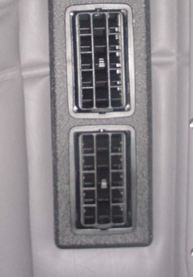
5 A/C DUCTING INSTALLATION Ducting kits are application specific. Depending on the application, some kits are designed to tie into the OEM ducting and others are universal and supplied with a 4 flex hose. In routing and installing the systems ducting, the following criteria must be observed: Route the ducting with smooth bends and transitions. Avoid crushing the duct work with tools and etc. Be sure all of the treated air is routed above the mattress as close to the driver s body as possible. Kits can be supplied with either a Tower Duct or a T-Duct. POWER KIT INSTALLATION (BATTERIES, ISOLATOR) BATTERIES The NITE system is powered by two (or 4 for upgraded) 6 volt batteries running in series to give you 12 volts. The batteries are a sealed, deep cycle, dry cell battery. They need to be mounted inside the provided battery box(es). The battery box(es) are generally mounted on the frame rail of the truck. However, if there is no room on the frame rail, the batteries may be mounted inside on of the trucks side storage compartments. Since the batteries are sealed and dry celled, there is no hazard in doing this. Things to observe when mounting the battery box(es): Find a general location on the frame rail, usually just behind one of the fuel tanks. Be sure to have at least 4 inches of free space on both sides of the battery box(es) to allow room for wiring and the rubber latches. Try to locate existing holes or bolts in the frame rail to capture. It is difficult to drill a ½ hole into the frame, so this will help ease the installation. 5

6 SEPARATOR The separator is mounted in the sleeper, under the mattress It is electrically connected between the truck batteries and the NITE batteries 6


7 NITE AIR CONDITIONING AND HEATING SYSTEM OPERATION MANUAL CONTROLS NO-IDLE AIR CONDITIONING NO-IDLE HEATING OFF LOW MEDIUM MAX OFF ON TEMPERATURE CONTROL BATTERY INDICATOR VENTILATOR OPERATION NOTES After 1 hour of operation, the MAX A/C setting will automatically switch to the MEDIUM A/C setting. This feature is done to provide optimum system energy efficiency. With the upgraded 4 battery system the max A/C setting remains constant. The heater ventilation mode is to be used for continuous operation of the heater at a pre-selected temperature setting. The temperature control knob has no function while in ventilation mode. The Green battery light indicates normal operation. When the battery light changes to Yellow, it indicates the batteries are at about half charge. The light will change to Red and the system will shut down automatically when the engine needs to be started in order to recharge the batteries. 7
8 NITE AIR CONDITIONING AND HEATING SYSTEM OPERATION NOTES For optimal comfort Bergstrom recommends to close the curtain between the cab and the sleeper when using the NITE A/C and heating system. The NITE A/C system is designed to maintain a comfortable temperature inside the cab without the engine running. The A/C unit will not pull down a hot cab that has been sitting in the sun without the factory A/C running. To assist the NITE system in cooling down the cab, start the engine and run the factory A/C system for a few minutes. This will help cool the cab to a respectable temperature. Once the cab is pulled down, the NITE system will maintain a comfortable temperature. The system must be turned off every time the system is not in use or the batteries May not charge properly. After use of the system be sure to turn the control knob to the off position, even if the unit is not running. BATTERIES & FUSES The system must be turned off every time the system is not in use or the batteries may not charge properly. After using the system turn the control back off, even if the unit is not running. The NITE A/C and heating system uses its own batteries. A battery isolator or separator keeps the starting batteries from being drawn down. The NITE A/C and heating system switches off automatically when batteries charge level is low. The A/C fuses (2) are located next to the NITE A/C unit, under the bunk. The parking heater fuse (1) is located inside the battery box. SERVICE The NITE A/C unit is not serviceable. If problems are encountered please contact the NITE line at
9 REQUIRED TOOLS 1) DRILL BITS (1/4, ½, ) 2) HOLE SAWS (4 1/8 OR 4 1/4) 3) ELECTRIC/AIR DRILL 4) SCREWDRIVERS (FLAT HEAD & PHILLIPS HEAD) 5) IMPACT GUN 6) AIRSAW/ JIGSAW (CUTTING SHEETMETAL) 7) TORX HEAD (T30) 8) METRIC WRENCHES 9) ENGLISH WRENCHES 10) ¼, 3/8 DRIVE RATCHETS 11) ENGLISH SOCKET SET 12) METRIC SOCKET SET 13) WIRE CUTTERS 14) TERMINAL CRIMPERS 15) WIRE STRIPPERS 16) RAZOR KNIFE 17) ELECTRICAL TAPE 9

 Cut out the (2) rectangular openings, (2) on")
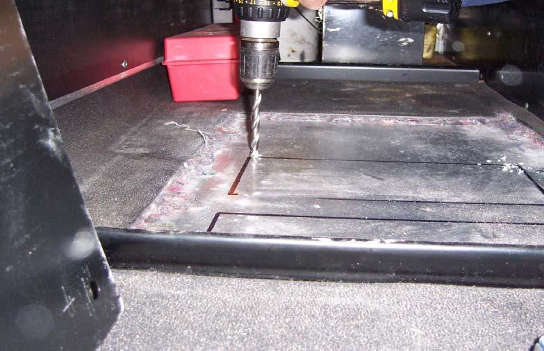
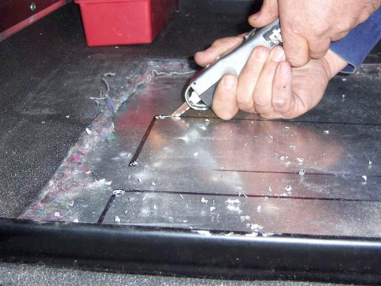
10 INSTALLATION INSTRUCTIONS 1) Disconnect ground wire from truck batteries. 2) Remove mattress from the sleeper. 3) Cut out the (2) rectangular openings, (2) on the floor and (1) on the front wall. 10


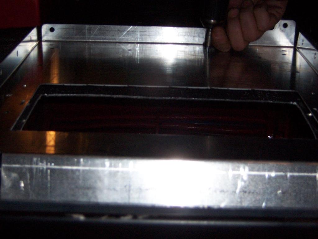
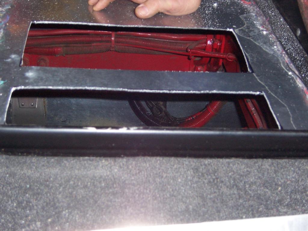
11 4) Remove the template and use an airsaw to cut out the three rectangle openings. Use a 1 3/8 hole saw for drilling the wiring hole. Finally use a ½ drill bit to drill out the two holes for unit mounting. 11
12 12
13 13
 The screws are then added to each corner connecting the mounting plate to the night system to securely hold the unit in place.")
14 5) Remove the 4 torx screws shown in red to allow clearance for the a/c unit to drop freely into the mounting plate 6) After removing the 4 torx screws the unit can then be placed on top of the mounting plate. 7) The screws are then added to each corner connecting the mounting plate to the night system to securely hold the unit in place. 14


15 8) The 90* elbow is then attached to the mounting bracket using Phillips screws. 10) Use the mounting plate as a template to mark the opening to be cut in the OEM duct as close to the elbow in the OEM duct as possible. 15


16 11) The hole is then cut out using the air saw. 16

 The mounting plate is then attached to the duct using black Phillips screws.")
17 12) A second hole must be cut about 2 to the right of the first hole. This hole should be about an 1/8 wide and the height of the duct. This hole will be used to locate the air blockage plate included in the kit. 13) The mounting plate is then attached to the duct using black Phillips screws. Note the baffle inside the duct. 17

 Remove the OEM air")
18 14) The 90* duct is then attached to mounting plate using Phillips screws. 15) Remove the OEM air louver. 18


19 16) Attach the included template around the louver opening. Cut the inside interior to allow the two larger louvers to be set into place. 19
20 20


21 17) Find a location on the OEM control panel to mount the NITE controls. Remove the control panel to insure factory wires are not damaged.during drilling. Now a 2 1/2 hole is to be drilled into the panel to allow the control to be mounted. 18) Attach the control switch to the OEM control using the black Phillips scews included in the kit.then attach the wires the the control. 21
22 ELECTRICAL SYSTEM BATTERY SEPARATOR The battery separator ties into the truck starting batteries. The separator puts charging priority to the starting batteries and then charges the Nite batteries. The NITE batteries begin charging after the starting batteries have reached 13.2 volts. 22
23
24
 USE THE 10 MOUNTING HOLES LOCATED ON THE BACK OF THE BATTERY BOX IN ORDER TO CAPTURE 4 EXISTING HOLES OR BOLTS ON THE FRAME RAIL.")
25 BATTERY BOX INSTALLATION INSTRUCTIONS 1) THE BATTERY BOX IS DESIGNED AS A UNIVERSAL MOUNTING TO BE BOLTED ON EITHER THE DRIVER S SIDE OR PASSENGER SIDE FRAME RAIL. 2) USE THE 10 MOUNTING HOLES LOCATED ON THE BACK OF THE BATTERY BOX IN ORDER TO CAPTURE 4 EXISTING HOLES OR BOLTS ON THE FRAME RAIL. 3) IF NO EMPTY HOLES OR BOLTS ARE EXCESSIBLE FOR MOUNTING THE BOX, DRILL (4) HALF INCH HOLES INTO THE FRAME RAIL USING THE FOUR OUTSIDE MOUNTING HOLES OF THE BATTERY BOX. CAUTION: WHEN DRILLING INTO THE FRAME RAIL, BE SURE TO STAY AT LEAST 40MM AWAY FROM THE TOP AND BOTTOM EDGE OF THE FRAME. NOTE: MOUNT THE BATTERY BOX ON THE FRAME RAIL CLOSE TO THE LOCATION OF THE FUEL TANK TO INSURE THE BATTERY CABLES WILL BE LONG ENOUGH. 4) USE THE PROVIDED ½ BOLTS AND LOCKNUTS TO BOLT THE BATTERY BOX TO THE FRAMERAIL USING AN IMPACT GUN. 5) PLACE THE TWO BATTERIES SIDE BY SIDE INSIDE THE BATTERY BOX. NOTE: BE SURE TO POSITION THE BATTERIES POWER AND GROUND OPPOSITE OF ONE ANOTHER. ONE BATTERIES GROUND WILL BE NEXT TO THE OTHER BATTERIES POSITIVE. 6) PLACE THE H -BRACKET ON TOP OF THE BATTERIES. NOW USE THE PROVIDED 11 BOLT AND RUN THROUGH THE TOP OF THE H-BRACKET BETWEEEN THE TWO BATTERIES. INSERT THE BOLT DOWN THROUGH THE HOLE IN THE BOTTOM ON THE BATTERY BOX AND FASTEN IS SECURELY WITH THE LOCKNUT. 7) NOW MAKE THE PROPER BATTERY CONNECTIONS AS SHOWN ON PAGE
26 NITE SYSTEM CHECK LIST 1. NITE unit basics The control of the NITE unit has 3 positions: Low, Medium and High. For each control position the compressor speed and the evaporator blower are set differently. The following table shows how the compressor and the blower are set for each control position: Control position Capacity setting Blower speed Compressor speed 1 Low Low Low 2 Medium High Low 3 High High High Note 1: there is no change of airflow when switching from position 2 to position 3. Only the compressor speed changes. Note 2: in addition to the evaporator blower and to the compressor there is another electrical device that makes the NITE system work: the condenser fan. As well as the compressor and the evaporator blower, the condenser fan is located inside the NITE unit. It sucks air from underneath the sleeper floor and blows it to the outside as well. Whatever the position of the control (low, medium or high), the condenser fan speed remains the same. Note 3: When the control is set on HIGH (position 3) the system will automatically switched to the MEDIUM setting after an hour of operation. This permits to increase the NITE system running time without affecting the performances. When this automatic switch is performed the compressor speed changes and the airflow (blower speed) remains the same. No such change occurs for an upgraded 4 battery system. 2. Checking of the different NITE unit components The following table explains out to check that the different components of the NITE unit are running correctly when the NITE unit is ON. The next paragraph will explain how to evaluate that the different components are working fine. Component Function How to check it is working Blows cold air inside the sleeper area, through the ducting The system is a 100% recirculation system; the air intakes (2) are located on top and side of the NITE unit Blower (evaporator) Switch the NITE control to position 1; you must feel air coming out of the duct louvers Then switch the NITE control to position 2; you must feel an increase of the airflow coming out of the duct louvers Note: make sure nothing blocks the air intake opening (recirculation) on the NITE unit 26
27 Component Function How to check it is working Fan (condenser) Takes ambient air under the sleeper floor and rejects it from the floor too The air goes through the condenser coil to cool it down Goes under the sleeper and check that air is going out the condenser air outlet when the NITE unit is running (inlet and outlet are located next to each other) On the inlet you must feel the air going into the NITE unit On the outlet you must feel the air Compressor Compresses and runs the refrigerant through the NITE unit refrigerant loop going out of the NITE unit. The best way to check that the compressor is running is to feel the compressor speed changes when the control is switched from position 2 to position 3 (the compressor speed goes from low to high). Set the control to position MEDIUM and lift up the bed, so that you can hear the NITE unit vibration & sound change. Wait 1 minute. Then set the control to position HIGH: you must notice a change in the vibration & sound of the NITE unit when the compressor speed changes. A better verification is to touch the unit (or have someone touching it) in order to feel the vibration changes. 3. NITE unit electrical and temperature checking The following instructions list how to check that the NITE unit is working properly NITE unit electrical power check the NITE unit voltage: close to the unit, on the power supply cables (red and black cables), there is a black connector on which the voltage can be read. When the NITE batteries are fully charged and when the control position is on HIGH, you must read between 12 and 12.5 volts check the NITE unit current: when the NITE unit control is on HIGH position and using a clamp-on inductive ammeter, measure the current on the NITE unit power supply RED cable. You must read between 27 and 35 Amps Louvers temperature check the louvers temperature: when the NITE unit control in on HIGH position, when the sleeper temperature is between 75 and 80 F and when the outside temperature is between 90 and 95 F, measure the temperature directly at one of the duct louvers. You must read between 55 and 62 F. 27
28 3.3. Condenser outlet temperature as described earlier in this document the NITE unit pulls air from outside, under the sleeper floor to cool down the condenser coil, then the air is rejected to the outside from the sleeper floor too. When the NITE unit is running in HIGH position, go under the sleeper and locate the condenser air outlet (rectangle opening with a screen). The temperature at the condenser outlet must be 10 to 20 F higher than the outside temperature 28
29 ELECTRICAL CHECK LIST NITE SYSTEM WITH SEPARATOR 1. Make sure you don t have any loose electrical connections 2. Check that the installation is done according to the electrical diagram 2.1. Make sure the 16 ga ground wire is connected to the bottom blade terminal of the separator on one end, and to any good ground on the other end (truck batteries ground, or NITE batteries ground, or frame(last choice)) 2.2. In case of a 2-battery system, make sure the 2 NITE batteries are connected in series with a jumper. In case of a 4-battery system, make sure the batteries are connected in series and parallel. Each battery is a 6 V one, the NITE system runs in 12 VDC Make sure the ground of the NITE batteries is connected to a good ground (truck batteries ground, or frame (last choice), or alternator ground) 2.4. Make sure the NITE unit power cables are connected to the correct terminals of the NITE batteries. The red cable goes to the positive terminal; the black cable goes to the ground. 3. Voltage checking engine OFF 3.1. Check that the voltage on the truck batteries is the same as the voltage on the separator (main batteries side). When you check the voltage on the separator, use the ground terminal on the separator. Both voltages should be the same Check that the voltage on the NITE batteries is the same as the voltage on the separator (aux batteries side). When you check the voltage on the separator, use the ground terminal on the separator. Both voltages should be the same (approx. 12 V) 29
30 4. Voltage checking engine ON The separator charges the batteries as follow: - when the engine is ON the alternator is going to start to charge the truck batteries first, until the truck batteries voltage reaches 13.2 V. During this period, the separator is open and the NITE batteries are not charged - when the truck batteries reaches 13.2 V, the separator closes and the NITE batteries are being charged 4.1. Engine ON, check the voltage of the truck batteries. It should be higher than the voltage when engine is OFF (> 13 V). 4.2 In order to check that the separator works properly, wait for the truck batteries voltage to reach at least 13.2 V. Increase the engine rpm if necessary. When the separator closes to start charging the NITE batteries, you can hear an audible click of the separator. Check the NITE batteries voltage. It should be higher than the voltage when the engine is OFF (approx. the voltage of the truck batteries) In order to double check that the separator allows the NITE batteries to be charged you can measure the Amps going to the NITE batteries, using a clamp-on type inductive ammeter, on the 4 ga cable that connects the separator to the NITE batteries positive terminal. It should be > 0 Amp. 30
TABLE OF CONTENTS INTRODUCTION 3. INSTALLATION PROCEDURES Air Conditioner Location 4. A/C Ducting Installation 5
 585474 1 TABLE OF CONTENTS SECTION PAGE INTRODUCTION 3 INSTALLATION PROCEDURES Air Conditioner Location 4 Air Conditioner Mounting 4 A/C Ducting Installation 5 Power Kit Installation (Batteries). 5 Separator...
Model 377, 379, 386, 388, Sleeper no window
 Installation Manual Model 377, 379, 386, 388, 389 63 Sleeper no window 2390 Blackhawk Road P.O. Box 6007 Rockford, IL 61125 www.nitesystem.com 1-866-204-8570 NITE Plus Installation Procedures 1-2 Table
Installation Manual Blackhawk Road Rockford, IL
 Installation Manual 2390 Blackhawk Road Rockford, IL 61072 815-874-7821 www.bergstrominc.com Table of Contents Introduction Before You Start Parts List Tools Required Installation Procedures Electrical
Installation Manual #
 FINAL 10/06/08 Installation Manual #1000067001 Cascadia Under Bunk Mounting Bergstrom, Inc. 2390 Blackhawk Road P.O. Box 6007 Rockford, IL 61125 www.nitesystem.com 1-866-204-8570 Table of Contents Introduction
Installation Manual #
 Final 10/01/08 Installation Manual # 585416 T600, T800 and W900 Bergstrom, Inc. 2390 Blackhawk Road P.O. Box 6007 Rockford, IL 61125 www.nitesystem.com 1-866-204-8570 Table of Contents Introduction Before
Installation Manual #
 FINAL 10/06/08 Installation Manual #1000067014 Bergstrom, Inc. 2390 Blackhawk Road P.O. Box 6007 Rockford, IL 61125 www.nitesystem.com 1-866-204-8570 Table of Contents Introduction Before You Start 3 4
Setting the World s Performance Standards
 Setting the World s Performance Standards 743 East Iona Road, Idaho Falls, ID 83401, (208) 529-0244 Fax (208) 529-9000 Forced Air Hot Air Elimination Kit (Bed Fan Kit) For 800 RZR-4 P/N 67-165 Kit Contents:
Kenworth T680 without factory installed heater
 Installation Manual Kenworth T680 without factory installed heater 2390 Blackhawk Road P.O. Box 6007 Rockford, IL 61125 www.nitesystem.com 1-866-204-8570 Table of Contents Introduction Before You Start
Air Conditioner for M915 A0/A1 Truck
 RD-2-4530-0 Air Conditioner for M915 A0/A1 Truck INSTALLATION INSTRUCTIONS Install refrigerant compressor per instructions provided with compressor mount kit. CAUTION: Edges of sheet metal can be sharp!
PERFECT FIT SERIES IN-DASH HEAT/ COOL/ DEFROST MUSTANG
 specializing in AIR CONDITIONING, PARTS AND SYSTEMS for your classic vehicle PERFECT FIT SERIES IN-DASH HEAT/ COOL/ DEFROST 1969-70 MUSTANG CONTROL & OPERATING INSTRUCTIONS The controls on your new Perfect
Installation Manual. Cascadia. For Phoenix Gen 4 units built after 6/26/2017
 Installation Manual Cascadia For Phoenix Gen 4 units built after 6/26/2017 2390 Blackhawk Road P.O. Box 6007 Rockford, IL 61125 www.nitesystem.com 1-866-204-8570 Table of Contents Introduction Before You
Classic Sleeper including T600, T660, T800 and W900
 Installation Manual Classic Sleeper including T600, T660, T800 and W900 2390 Blackhawk Road P.O. Box 6007 Rockford, IL 61125 www.nitesystem.com 1-866-204-8570 Table Installation of Contents Procedures
Installation Manual. Underbunk Columbia and Century models Blackhawk Road P.O. Box 6007 Rockford, IL
 Installation Manual Underbunk Columbia and Century models 2390 Blackhawk Road P.O. Box 6007 Rockford, IL 61125 www.nitesystem.com 1-866-204-8570 Table of Contents Introduction Before You Start Parts List
Kenworth T680 without factory installed heater
 Installation Manual Kenworth T680 without factory installed heater For Phoenix Gen 4 units built after 6/26/2017 2390 Blackhawk Road P.O. Box 6007 Rockford, IL 61125 www.nitesystem.com 1-866-204-8570 8-31-17
Technical Information and Diagnostic Guide
 Technical Information and Diagnostic Guide This guide will assist you in becoming more familiar with the working components of the NITE System and the proper steps and procedures to completely diagnose
Installation Manual. 9000i Passenger side install Blackhawk Road P.O. Box 6007 Rockford, IL
 Installation Manual 9000i Passenger side install 2390 Blackhawk Road P.O. Box 6007 Rockford, IL 61125 www.nitesystem.com 1-866-204-8570 Table of Contents Introduction Before You Start Parts List Tools
Installation Manual CLASSIC SLEEPER NO WORKSTATION Blackhawk Road P.O. Box 6007 Rockford, IL
 Installation Manual CLASSIC SLEEPER NO WORKSTATION 2390 Blackhawk Road P.O. Box 6007 Rockford, IL 61125 www.nitesystem.com 1-866-204-8570 Table of Contents Introduction Before You Start Parts List Tools
SECOND GENERATION Use this guide with unit serial number prefix beginning with BWF using Terra Power separator.
 Technical Information and Diagnostic Guide for SECOND GENERATION Use this guide with unit serial number prefix beginning with BWF using Terra Power separator. This guide will assist you in becoming more
Installation Manual. CH, CL, CXU, CXN and Vision Blackhawk Road P.O. Box 6007 Rockford, IL
 Installation Manual CH, CL, CXU, CXN and Vision 2390 Blackhawk Road P.O. Box 6007 Rockford, IL 61125 www.nitesystem.com 1-866-204-8570 Table of Contents Introduction Before You Start Parts List Tools Required
Installation Instruction for '84-'89 Nissan 300ZX High Performance Intercooler System (Part No )
") Installation Instruction for '84-'89 Nissan 300ZX High Performance Intercooler System (Part No. 2-124) Page ii DCB (06/14/02 12:19 AM) Version 1.0 Page iii Table of Contents 1. TOOLS REQUIRED...1 2. INSTALLATION
Installation Instruction for '84-'89 Nissan 300ZX High Performance Intercooler System (Part No. 2-124) Page ii DCB (06/14/02 12:19 AM) Version 1.0 Page iii Table of Contents 1. TOOLS REQUIRED...1 2. INSTALLATION
Procharger Stage II Intercooled Supercharger System (11-14 GT)
") Procharger Stage II Intercooled Supercharger System (11-14 GT) Installation Time: Approximately one day. Installed on 2012 Mustang GT 5.0/Manual Required Tools 3/8 Socket Set (Standard and Metric) 1/2
Procharger Stage II Intercooled Supercharger System (11-14 GT) Installation Time: Approximately one day. Installed on 2012 Mustang GT 5.0/Manual Required Tools 3/8 Socket Set (Standard and Metric) 1/2
Wiring diagrams on page 29 are for reference only. For detailed vehicle wiring refer to Navistar documents.
 1 10/2014 REV 7 !!Attention!! Before performing diagnostics: Wiring diagrams on page 29 are for reference only. For detailed vehicle wiring refer to Navistar documents. Check for Fault Codes using the
Adjustable Light Kits E-Z-Go TXT All Models Installation Instructions
 Adjustable Light Kits E-Z-Go TXT All Models 1996-2013 Installation Instructions Caution: Please read through the instructions carefully. Before starting this project, remove the system s positive and negative
Jeep Wrangler TJ. Complete Air Conditioning System. Slide Control Head. Installation instructions
 WWW.JEEPAIR.COM 1996-1998 Jeep Wrangler TJ Complete Air Conditioning System Slide Control Head Installation instructions Kit Information After 1994 every vehicle was designed for R134a refrigerant. The
Third Generation NITE Phoenix
 Technical Information and Diagnostic Guide for Third Generation NITE Phoenix Use this guide with unit serial number prefix beginning with BYC, CAI built after 2-10-2012 and CCA, CDJ, CIA units after 6/25/2012
PERFECT FIT SERIES IN-DASH HEAT/ COOL/ DEFROST 1969 CHEVROLET CAMARO/ FIREBIRD NOTE: INSTRUCTIONS DEPICT CAMARO
 specializing in AIR CONDITIONING, PARTS AND SYSTEMS for your classic vehicle PERFECT FIT SERIES IN-DASH HEAT/ COOL/ DEFROST 1969 CHEVROLET CAMARO/ FIREBIRD NOTE: INSTRUCTIONS DEPICT CAMARO CONTROL & OPERATING
This harness kit includes: Installing the Hybrid ReVolt Universal grid charger in an Insight
 Installing the Hybrid ReVolt Universal grid charger in an Insight This harness kit includes: Insight harness (2000 to 2006) (a) 4 #6 mounting screws for bulkhead (c) 2 sheet metal screws for fan board
& 76 CHEVROLET NOVA HEATER ONLY
 specializing in AIR CONDITIONING, PARTS AND SYSTEMS for your classic hi l PERFECT FIT IN-DASH HEAT/ COOL/ DEFROST 1969-74 & 76 CHEVROLET NOVA HEATER ONLY CONTROL & OPERATING INSTRUCTIONS The controls on
LGT-312L E-Z-Go TXT Light Bar Bumper Kit Installation Instructions
 LGT-312L E-Z-Go TXT 2014+ Light Bar Bumper Kit Installation Instructions Caution: Please read through the instructions carefully. Before starting this project, remove the system s positive and negative
1963 GEN IV SUREFIT VINTAGE AIR CONDITIONING INSTALLATION
 by Randy Irwin 1963 GEN IV SUREFIT VINTAGE AIR CONDITIONING INSTALLATION Randy Irwin - Technical Writer Randy has been involved in the Chevy parts business for over 30 years. He is a wizard at creating,
Jeep Wrangler 4.0 Liter TJ Jeep Wrangler 2.5 Liter TJ Installation instructions
 TM www.jeepair.com 1999 Jeep Wrangler 4.0 Liter TJ 1999-2001 Jeep Wrangler 2.5 Liter TJ Installation instructions Kit Information After 1994 every vehicle was designed for R134a refrigerant. The Jeep kit
INSTALLATION & OWNER S MANUAL
 INSTALLATION & OWNER S MANUAL CAB INSTALLATION INSTRUCTIONS JOHN DEERE 3000 SERIES (4200/4300/4400) (4210/4310/4410) & (3120/3320/3520/3720) HARD SIDED CAB ENCLOSURE (p/n 1JD3520AS) SOFT SIDED CAB ENCLOSURE
Installation Instruction for '84-'89 Nissan 300ZX High Performance Intercooler System (Part No )
") Installation Instruction for '84-'89 Nissan 300ZX High Performance Intercooler System (Part No. 2-124) Routing of the Intercooler Pipe It is necessary to follow the exact sequence of the installation
Installation Instruction for '84-'89 Nissan 300ZX High Performance Intercooler System (Part No. 2-124) Routing of the Intercooler Pipe It is necessary to follow the exact sequence of the installation
INSTALLATION INSTRUCTIONS
 INSTALLATION INSTRUCTIONS Part# 22-7810 Add On Kit for Your ADS System Contents: Complete Install Kit for Your ARB CKMTA12V Compressor For the most up-to-date instructions please visit www.updownair.com
Installation Instructions for Lingenfelter GM 2500 Suburban & Yukon XL Auxiliary Fan System (with AC clutch controlled fan output)
") Installation Instructions for Lingenfelter 2007-2013 GM 2500 Suburban & Yukon XL Auxiliary Fan System (with AC clutch controlled fan output) PN L300080607 Revision - 1.1 Lingenfelter Performance Engineering
Installation Instructions for Lingenfelter 2007-2013 GM 2500 Suburban & Yukon XL Auxiliary Fan System (with AC clutch controlled fan output) PN L300080607 Revision - 1.1 Lingenfelter Performance Engineering
PERFECT FIT IN-DASH HEAT/ COOL/ DEFROST FORD FAIRLANE & CROWN VICTORIA
 PERFECT FIT IN-DASH HEAT/ COOL/ DEFROST 1955-56 FORD FAIRLANE & CROWN VICTORIA CONTROL & OPERATING INSTRUCTIONS The controls on your new Perfect Fit system, offer complete comfort capabilities in virtually
PRODUCT SAFETY NOTICE
 PRODUCT SAFETY NOTICE Congratulations. This vehicle has been equipped with a Firestone air suspension system. This suspension will enhance the vehicle s handling when loaded, however, the vehicle s performance
Technical Support (707)
") Installation Instructions CONSOLE MEGASHIFTER Fits: 1982-1992 Camaro & Firebird w/automatic Transmission *except 1988-1992 Firebird Formula Model Catalog # 80692 WORK SAFELY! For maximum safety, perform
Installation Instructions CONSOLE MEGASHIFTER Fits: 1982-1992 Camaro & Firebird w/automatic Transmission *except 1988-1992 Firebird Formula Model Catalog # 80692 WORK SAFELY! For maximum safety, perform
GPS AutoSteer System Installation Manual
 GPS AutoSteer System Installation Manual Supported Vehicles New Holland Combines CR 9040 CX 9040 CR 9050 CX 9050 CR 9060 CX 9060 CR 9070 CX 9070 CR 9080 CX 9080 IntelliSteer Ready PN: 602-0231-01-A LEGAL
Technical Information and Diagnostic Guide RestStar Use this guide with 5700XE RestStar Unit. Western Star 5700XE.
 Western Star 5700XE RestStar 4 10-2017 1 Technical Information and Diagnostic Guide RestStar Use this guide with 5700XE RestStar Unit 2390 Blackhawk Road P.O. Box 6007 Rockford, IL 61125 nitesystem.com
6945 (12v) 6944 (24V) installation instructions
 6944 (24V) installation instructions") 6945 (12v) 6944 (24V) installation instructions included: tools needed: Cordless drill Breezeeasy Fan Mounting brackets 1/4 Drill Bit 10mm Socket Hardware Pack 10mm Wrench Fuse Assembly Wire Stripper Crimper
6945 (12v) 6944 (24V) installation instructions included: tools needed: Cordless drill Breezeeasy Fan Mounting brackets 1/4 Drill Bit 10mm Socket Hardware Pack 10mm Wrench Fuse Assembly Wire Stripper Crimper
INDUSTRY STANDARD BASE RAIL UNIVERSAL MOUNTING KIT PART NUMBER 2720
 INDUSTRY STANDARD BASE RAIL UNIVERSAL MOUNTING KIT PART NUMBER 2720 INSTALLATION INSTRUCTIONS Introduction The following steps provide general and vehicle-specific instructions for the installation of
Jeep Wrangler TJ 4.0 LITER Installation instructions
 www.jeepair.com 2000-2001 Jeep Wrangler TJ 4.0 LITER Installation instructions Important information about your system, and warranty DO NOT ADD ANY OIL TO ANY PART OF THE SYSTEM. DO NOT USE THE SIGHT GLASS
REV 1 THE GRIP IDLE MANAGEMENT SYSTEM
 INSTALLATION MANUAL This manual will provide the installer with the necessary information to install the GRIP system and all of its optional equipment on most vehicle configurations. This book also contains
ITEM QTY CHECK PART NUMBER DESCRIPTION
 PART #21128 2010 Camaro Cold Air Induction Stage II PACKING LIST Before installation, use this check list to make sure all necessary parts have been included. ITEM QTY CHECK PART NUMBER DESCRIPTION 1.
WPS-104 Heater Installation Instructions For 500EFI, 700 XP, & Crew Applications
 WPS-104 Heater Installation Instructions For 500EFI, 700 XP, & Crew Applications ORDER OF INSTALLATION FOR A COMPLETE ENCLOSURE OF A RANGERWARE WPS (Weather Protection System) IS AS FOLLOWS: 1. Heater
GPS AutoSteer System Installation Manual
 GPS AutoSteer System Installation Manual John Deere Track Supported Models 8295RT 8320RT 8345RT PN: 602-0255-01-A LEGAL DISCLAIMER Note: Read and follow ALL instructions in this manual carefully before
INSTALLATION INSTRUCTIONS
 COLD AIR INTAKE INSTALLATION INSTRUCTIONS PART NUMBER D760-0390C APPLICATION: 1999-2003 E39 M5 PARTS LIST 1 Left Aluminum Intake Tube 1 Air Pump Bracket (A) 1 Right Aluminum Intake Tube 1 Air Pump Bracket
INSTALLATION & OWNER S MANUAL
 INSTALLATION & OWNER S MANUAL CAB INSTALLATION INSTRUCTIONS MASSEY FERGUSON TGX SERIES SOFT SIDED CAB ENCLOSURE (p/n MFTGXSS) This Curtis Cab is designed and manufactured for use only as reasonable weather
PRODUCT SAFETY NOTICE DEALER/INSTALLER NOTICE
 PRODUCT SAFETY NOTICE Congratulations. This vehicle has been equipped with a Firestone air suspension system. This suspension will enhance the vehicle s handling when loaded, however, the vehicle s performance
INSTALLATION & OWNER S MANUAL
 INDUSTRIES, LLC. INSTALLATION & OWNER S MANUAL CAB INSTALLATION INSTRUCTIONS KUBOTA GRAND L 40 SERIES HARD SIDED CAB ENCLOSURE (p/n 1KGL4AS) This Curtis Cab is designed and manufactured for use only as
EFFICIENT SLEEPER COMFORT. Volvo s Battery-powered Parking Cooler Option
 EFFICIENT SLEEPER COMFORT Volvo s Battery-powered Parking Cooler Option Cooling comfort and anti-idle value. Most environmentally-friendly and efficient solution for sleeper comfort Overnight comfort without
R-4122 Sleeper Heater/ Air Conditioner Unit. R-2550 Heater/Air Conditioner Unit RED DOT UNITS HEATER-A/C RESCUE VEHICLES
 R-2550 Heater/Air Conditioner Unit RESCUE VEHICLES The R-2550 is specifically designed for ambulances and other lighter-duty vehicles with large interior spaces to heat and cool quickly. R-2550 SPECIFICATIONS
INSTALLATION INSTRUCTIONS
 Rear Vision System Tailgate Emblem Camera Mirror Display 2009-Current Ford F-150 and 2010-Current Super Duty (Kit part number 1008-9527) Kit Contents: Mirror Tailgate Emblem Mount with Camera Interior
Sturdy Truck Body Poultry Shipping Truck - Operations Manual August 2003
 1.0 Introduction The Sturdy ventilation controller is designed to automatically control indoor air quality including: temperature, relative humidity, carbon dioxide and oxygen in the interior of the vehicle
INSTALLATION & OWNER S MANUAL
 1 of 18 INSTALLATION & OWNER S MANUAL (*Not including cab & other accessories) A/C Alternator Kit: Yamaha Drive & Drive2 P/N: 1ACYDR2DRK Recommended it be installed with Curtis Cab: Sandstone (p/n 1GCYD1-A,
INSTALLATION INSTRUCTIONS JEEP 2011-UP JK SECURITY FULL CONSOLE #274
 INSTALLATION INSTRUCTIONS JEEP 2011-UP JK SECURITY FULL CONSOLE #274 PARTS CHECKLIST Tuffy Console #9 Left Front Mounting Bracket #10 Right Front Mounting Bracket #11 Electronics mounting bracket #12 Divider
Ram 1500 Crew Cab A Ram 2500/3500 Crew Cab A
 I N S T A L L A T I O N G U I D E APPLICATION AMP Part # Ram 1500 Crew Cab 2013-2015 77138-01A Ram 2500/3500 Crew Cab 2013-2015 77138-01A Note:The application works only on the Crew Cab model Vehicles.
INSTALLATION INSTRUCTIONS AIR/OIL SEPARATOR KIT
 INSTALLATION INSTRUCTIONS AIR/OIL SEPARATOR KIT 2015+ SUBARU WRX (LHD ONLY) Document: 19-0136 Support: info@radiumauto.com This document covers the installation of the Radium brake master cylinder brace
SCION xd INTERIOR LIGHTING UPGRADE Preparation
 Preparation Part Number: PTS21-52085 Light Guide Kit Contents Item # Quantity Reqd. Description 1 1 Controller Board, 4 color programmed w/ Bracket 2 1 RGB, LED Engine wire harness 3 2 14mm Light Rod,
Document: LIT-MAN-UNV-2 Rev A 10/21/15
 Document: LIT-MAN-UNV-2 Rev A 10/21/15 Limited Warranty This Product is warranted to be free from defects in manufacturing and workmanship and is guaranteed to work for three years or 36,000 miles, or
PHASE 3 POWERSPORTS AUDIO KIT RZR POLARIS. pg 2 Disassembly, Wire and Amplifier Plate Installation. pg 9 Glovebox Subwoofer Installation
 POLARIS RZR PHASE 3 POWERSPORTS AUDIO KIT pg 2 Disassembly, Wire and Amplifier Plate Installation pg 9 Glovebox Subwoofer Installation pg 13 Kick Panel Speakers Installation pg 25 MRB3 and Dash Kit Installation
Depress each tab as you pull the bezel off. The bezels are tight. L.H. shown.
 2013-2014 Ford Mustang V6 & Boss 302 Lower Valance Fog Light Kit Parts List: Quantity: Tool List: Fog light & bulb with bracket 2 Flat head & Phillips screwdriver Black bezels 2 Ratchet & Socket set OR
Chevrolet Truck Install Instructions. This kit is designed for the Chevrolet or GMC trucks without factory air conditioning.
 1967-1972 Chevrolet Truck Install Instructions This kit is designed for the 1967-1972 Chevrolet or GMC trucks without factory air conditioning. Glove box Heater box Heater box firewall cover Controls and
Subaru Front Mount Intercooler Kit STI Subaru Front Mount Intercooler Kit STI
 Subaru Front Mount Intercooler Kit STI 2008-2014 715500 Subaru Front Mount Intercooler Kit STI 2008-2014 Congratulations on your purchase of the Subaru Front Mount Intercooler Kit STI 2008-2014. The following
Installation Instructions for Lingenfelter GM 2500 Suburban & Yukon XL Auxiliary Fan System (with ECM controlled fan output)
") Installation Instructions for Lingenfelter 2007-2013 GM 2500 Suburban & Yukon XL Auxiliary Fan System (with ECM controlled fan output) PN L300090607 Revision - 1.1 Lingenfelter Performance Engineering
Installation Instructions for Lingenfelter 2007-2013 GM 2500 Suburban & Yukon XL Auxiliary Fan System (with ECM controlled fan output) PN L300090607 Revision - 1.1 Lingenfelter Performance Engineering
08-18 STI Flex Fuel Bluetooth Mk2 Kit Install Instructions For Cobb Tuning Access Port
 For Cobb Tuning Access Port Delicious Tuning 1948 Don Lee Place Suite #7 Escondido, CA 92029 408-480-0995 Rough Draft BJP Rev: 2.0 Date: 2/1/17 FFBT parts: (1) Ethanol Content Analyzer Module (1) Ethanol
GVW AGM Auxiliary Battery Kit for Air-cooled Westfalia Campers and all Vanagon NON-campers
 GVW-253-701AGM Auxiliary Battery Kit for 1980-1983 Air-cooled Westfalia Campers and all Vanagon NON-campers The purpose of this kit is to add an Interstate SLA1161 battery as an auxiliary battery under
LGT-306L / LB Club Car Precedent LED Light Bar Bumper Kit Installation Instructions
 LGT-306L / LB Club Car Precedent LED Light Bar Bumper Kit Installation Instructions Caution: Please read through the instructions carefully. Before starting this project, remove the system s positive and
INSTALLATION INSTRUCTIONS
 INSTALLATION INSTRUCTIONS Part# 69-0717 AIR IT UP 4 Tire On Board Installed Air Delivery System with Rear Mounted Controller (Requires External Air Source) For the most up-to-date instructions please visit
Installation Instructions
 Installation Instructions Speedcook Oven Read carefully. Keep these Instructions. INSTALLATION INSTRUCTIONS Electrical Requirements Product rating is 240/208 volts AC, 60 Hertz, 30 amps and 6.5 kilowatts.
TOYOTA TUNDRA COLD AIR INTAKE Preparation SEQUOIA
 Preparation SEQUOIA 2008 - Part Number: PTR03-34070 (5.7L) PTR03-34072 (4.7L) Kit Contents: 5.7L Item # Quantity Reqd. Description 1 1 Lid: Air Filter 2 1 Inlet Pipe: 5.7L 3 1 Air Filter: TRD Conical 4
JODALE PERRY. Parts List & Mounting Instructions. Jacobsen HR9016 JDP BUILT FOR LIFE
 JODALE PERRY Parts List & Mounting Instructions Jacobsen HR9016 JDP BUILT FOR LIFE Jacobsen HR9016 Mounting Instructions Standard Parts 1 - LH Rear Mounting Bracket 1 - RH Rear Mounting Bracket 1 - Front
Installation Instructions
 Installation Instructions (2) 10-24 Black flathead Allen Screws Tailgate End Front Cover Passenger Side Rail (has inspected by sticker under rail) (4) 10-32 Screws (stainless) Front Cover Exploded View
KK-K9-F16-K INSTALLATION INSTRUCTIONS K9 Kit for FORD EXPLORER (Retail Model Vehicle with OEM Center Shifter Console)
") KK-K9-F16-K INSTALLATION INSTRUCTIONS K9 Kit for 2011-2016 FORD EXPLORER (Retail Model Vehicle with OEM Center Shifter Console) TOOLS Needed: Phillips Screw Driver Power Drill with Drill Bits Trim panel
KK-K9-F16-K INSTALLATION INSTRUCTIONS K9 Kit for 2011-2016 FORD EXPLORER (Retail Model Vehicle with OEM Center Shifter Console) TOOLS Needed: Phillips Screw Driver Power Drill with Drill Bits Trim panel
INSTALLATION INSTRUCTIONS FUEL SURGE TANK KIT
 INSTALLATION INSTRUCTIONS FUEL SURGE TANK KIT BMW E46 3-Series, Excl Convertible Document: 19-0056 Support: info@radiumauto.com Relieve fuel pressure in vehicle before beginingthe installation. Disconnect
INSTALLATION INSTRUCTIONS
 INSTALLATION INSTRUCTIONS Accessory Application Publications No. SECURITY SYSTEM P/N 08E49-SDA-100 ACCORD 2- AND 4-DOOR AII 30666 Issue Date AUG 2005 PARTS LIST Hood switch harness Illustration of the
REARVIEW MIRROR AND BACKUP CAMERA KIT
 REARVIEW MIRROR AND BACKUP CAMERA KIT P/N 2881483 APPLICATION Verify accessory fitment at Polaris.com. BEFORE YOU BEGIN Read these instructions and check to be sure all parts and tools are accounted for.
Factory Five Racing, Inc. 818 Kit Assembly manual revision 1J update
 Factory Five Racing, Inc. 818 Kit Assembly manual revision 1J update Turbo coolant overflow tank...1 Shifter handle...4 Install...4 Door skin...7 Door Liner... 10 Side mirrors... 14 Door handles and pulls...
C40008 & C40009 EXHAUST BRAKES
 EXHAUST BRAKES C40008 & C40009 1995 2003 Ford F250 / F350 7.3 L Powerstroke Diesel with manual transmissions 1995 1998 Ford F250 / F350 7.3 L Powerstroke Diesel with automatic transmission* *Requires the
MF 9690, 9790, Challenger 660, 670
 Ag Leader Technology Parts List Note: Indented items indicate parts included in an assembly listed above Quantity by Model Part Name/Description Part No. MF 9690 MF 9790 Challenger 660 Challenger 670 Instruction
C44090 HP325 PACBRAKE COMPRESSOR CONVERSION
 C44090 HP325 PACBRAKE COMPRESSOR CONVERSION APPLICATIONS: DODGE 2003-2007 5.9L CUMMINS Compressor Replacement Instructions for C14030, C14045, C44030, C44045, C44049 & C44052 with Air Tank KIT CONTENTS
General safety and installation information.
 Read these instructions before connecting and using your PowerBright Pure Sine Power Inverters. Failure in observing this warning may result in injury to persons and damage to equipment. General safety
Turner M50 Manifold Adapter Install. April 26, 2012
 April 26, 2012 Models: 1996-99 E36 328i/M3; 1997-98 E39 528i, 1997-98 Z3 2.8, 1998-2000 MZ3 S52 Product(s): Turner M50 Manifold Adapter Kit Subject: Installation Guidelines and Tips This guide will aid
INSTALLATION INSTRUCTIONS
 INSTALLATION INSTRUCTIONS Accessory HITCH Application 2009 CR-V Publications No. AII 40373 Issue Date AUG 2008 PARTS LIST Plain washer, 12 mm Trailer Hitch Kit P/N 08L92-SWA-100 Trailer hitch 6 Spring
INSTALLATION INSTRUCTIONS
 INSTALLATION INSTRUCTIONS Part# 22-2719 Complete Mounting System for Dual Viair Compressors For the most up-to-date instructions please visit www.updownair.com www.updownair.com 833-226-4863 I M P O R
HUMMER H A. 3-5 Hours INSTALLATION GUIDE INSTALLATION TIME SKILL LEVEL. 4= Experienced TOOLS REQUIRED APPLICATION MODEL YR PART #
 INSTALLATION GUIDE APPLICATION MODEL YR PART # HUMMER H2 2003-2009 75107-01A INSTALLATION TIME 3-5 Hours Professional installation recommended SKILL LEVEL 1 2 3 = Experienced TOOLS REQUIRED Safety goggles
Ford Racing 4.6L 3V Crate Engine Control Pack
 Ford Racing 4.6L 3V Crate Engine Control Pack Installation Time: 3-6 hours on a Foxbody Mustang Tools Required: Basic English and Metric Socket and Wrench Set Flat and Phillips Screwdrivers Torx bits Hammer
This harness kit includes: Civic harness (2003 to 2005) Installing the Hybrid ReVolt Universal grid charger in a First Gen Civic ( )
 Installing the Hybrid ReVolt Universal grid charger in a First Gen Civic ( )") Installing the Hybrid ReVolt Universal grid charger in a First Gen Civic (2003-2005) This harness kit includes: Civic harness (2003 to 2005) (a) 1 HV warning label (c) 1 charger connector cover (e) 4 #6
Installing the Hybrid ReVolt Universal grid charger in a First Gen Civic (2003-2005) This harness kit includes: Civic harness (2003 to 2005) (a) 1 HV warning label (c) 1 charger connector cover (e) 4 #6
GPS AutoSteer System Installation Manual
 GPS AutoSteer System Installation Manual Supported Vehicles Case IH Vehicles Case 2577 Combines Case 2588 Combines Accuguide Ready PN: 602-0233-01-A LEGAL DISCLAIMER Note: Read and follow ALL instructions
1. Disconnect the battery. This is important! This will prevent air bag deployment.
 PARTS PACKING LIST Evaporator assembly Drain tube Plastic air plug Hardware package 11040 3601 W. Clarendon Phoenix, Arizona 85019 (602) 233-0090 800-648-4475 www.ackits.com 2003-4 Jeep Wrangler EVAPORATOR
INSTALLATION & OWNER S MANUAL
 Rev. B, p. 1 of 25 INSTALLATION & OWNER S MANUAL POLARIS RANGER RCS (for models XP or HD) (for model years 2009-) cab without doors kit (p/n 1POLRCWD) cab with doors kit (p/n 1POLRC) doors only kit (p/n
PRODUCT INSTRUCTIONS
 PRODUCT INSTRUCTIONS Thank you for purchasing genuine Design Engineering, Inc. products. Be sure to always wear the proper safety equipment when installing any DEI product. Design Engineering Inc. WILL
Part# JL AIR IT UP 4 Tire On Board Air Delivery System. (Requires External Air Source)
") Part# 18-1819 JL AIR IT UP 4 Tire On Board Air Delivery System (Requires External Air Source) The most up-to-date instructions always visit www.updownair.com www.updownair.com 833-226-4863 I M P O R T
Part# 18-1819 JL AIR IT UP 4 Tire On Board Air Delivery System (Requires External Air Source) The most up-to-date instructions always visit www.updownair.com www.updownair.com 833-226-4863 I M P O R T
= Experienced
 I N S T A L L A T I O N G U I D E APPLICATION LENGTH MODEL YR PART # Ford F-250 / F-350 / F-450 Regular Cab * (48 ) 2002-2003, 2008-2012 75134-01A Ford F-250 / F-350 / F-450 Super Cab * (60 ) 2002-2003,
LGT-311L Bumper LED Light Kit EZ-Go RXV Installation Instructions
 LGT-311L Bumper LED Light Kit EZ-Go RXV Installation Instructions Caution: Please read through the instructions carefully. Before starting this project, remove the system s positive and negative connections
INSTALLATION & OWNER S MANUAL
 INSTALLATION & OWNER S MANUAL CAB INSTALLATION INSTRUCTIONS JOHN DEERE 4000 SERIES (4500/4600/4700) (4510/4610/4710) (4120/4320/4520/4720) HARD SIDED CAB ENCLOSURE (p/n 1JD4120AS) SOFT SIDED CAB ENCLOSURE
INSTALLATION INSTRUCTIONS CWEH6-K WALL MOUNT HOOD
 Read and Save These Instructions All Hoods Must Be Installed By A Qualified Installer INSTALLATION INSTRUCTIONS CWEH6-K WALL MOUNT HOOD Read All Instructions Thoroughly Before Beginning Installation WARNING
BD Venom Dual Fuel F O R D 6. 7 L P O W E R S T R O K E Installation Instructions
 U 21 March 2017 (1050470) Venom Dual Fuel Kit (I-00390) 1 DOWNLOAD ENHANCED INSTALL MANUALS AT dieselperformance.com BD Venom Dual Fuel 2 0 1 1-2 0 1 6 F O R D 6. 7 L P O W E R S T R O K E Installation
FACTORY AIR CONVERSION HEAT/ COOL/ DEFROST CHEVROLET CHEVELLE
 specializing in AIR CONDITIONING, PARTS AND SYSTEMS for your classic vehicle FACTORY AIR CONVERSION HEAT/ COOL/ DEFROST 1970-72 CHEVROLET CHEVELLE CONTROL & OPERATING INSTRUCTIONS The controls on your