THERMAL ENGINEERING. Mr. S. BINSON M.E
|
|
|
- Randell Adams
- 5 years ago
- Views:
Transcription

1 A Course Material on By Mr. S. BINSON M.E ASSISTANT PROFESSOR DEPARTMENT OF MECHANICAL ENGINEERING SASURIE COLLEGE OF ENGINEERING VIJAYAMANGALAM
2 QUALITY CERTIFICATE This is to certify that the e-course material Subject Code Subject Class : ME6404 : THERMAL ENGIEERING : II Year MECHANICAL ENGINEERING being prepared by me and it meets the knowledge requirement of the university curriculum. Signature of the Author Name: Designation: S.BINSON ASSISTANT PROFESSOR This is to certify that the course material being prepared by Mr.S.Binson is of adequate quality. He has referred more than five books among them minimum one is from abroad author. Name: SEAL Signature of HD
3 CONTENTS SL NO TOPICS PAGE NO UNIT I GAS POWER CYCLES 1.1 Prerequisite Discussions 1.2 Power Cycles 1.3 Ideal Cycles 1.4 Gas Power Cycles 1.5 Engine Terms 1.6 Otto Cycle 1.7 Process Of Otto Cycle 1.8 Diesel Cycle 1.9 Processes Of Diesel Cycle 1.10 Dual Cycle 1.11 Process Of Dual Cycle Brayton Cycle Real Time Applications 1.14 Technical Terms 1.15 Solved Problems 1.16 Review Questions UNIT II INTERNAL COMBUSTION ENGINES 2.1 Prerequisite Discussions The Concept of IC Engine Significance Classification of IC Engines Components and functions of IC Engines
4 CONTENTS SL NO TOPICS PAGE NO 2.6 Theoretical valve timing diagram of four stroke engine Actual valve timing diagram of four stroke engine Theoretical port timing diagram of two stroke engine Comparison of two stroke and four stroke engines Fuel systems Carburetor Fuel Injection Fuel Injector Diesel knocking and detonation Ignition system Comparison between Battery and Magneto Ignition System Lubrication System Splash Force Feed Full Forced Feed Cooling System Air cooled system Water cooling system Thermo Syphon System Pump Circulation System Performance Calculation Exhaust Smoke and Other Emissions Technical terms Solved Problems Review questions 45 50
5 CONTENTS UNIT III STEAM NOZZLES AND TURBINES SL NO TOPICS PAGE NO 3.1 Prerequisite discussions Introduction Flow Through Nozzles Shapes of nozzles Significance of steam turbines Turbines Impulse Turbines Schematic diagram of an Impulse Trubine Velocity diagram of an Impulse Turbine The Single-Stage Impulse Turbine Compounding in Impulse Turbine The Velocity - Compounding of the Impulse Turbine Pressure Compounding Reaction Turbine Applications Governing of Steam Turbine Throttle Governing Nozzle Governing Solved Problems: Technical terms Review questions 66 UNIT IV AIR COMPRESSORS 4.1 Prerequisite discussion Concept of air compressor Significance of air compressors 69
6 CONTENTS S.NO TOPICS PAGE NO 4.4 Classification of air compressors Positive displacement compressor Dynamic compressors: Reciprocating compressors Rotary vane compressors Multistage compression: Work done Volumetric efficiency Application of compressors Technical terms Solved problems Review questions 89 UNIT V REFRIGERATION AND AIR CONDITIONING 5.1 Prerequisite discussion Concept of refrigeration Significance Classification of refrigeration system Vapour compression refrigeration Vapour absorption refrigeration Vapour absorption and vapour compression Performance Applications of refrigeratrion Concept of air conditioning Types of air conditioners Room Air Conditioner Zoned Systems 97
7 CONTENTS S.NO TOPICS PAGE NO Central Air Conditioning Unitary Systems Window Air-Conditioning System Split Air-Conditioning System Solved problems Technical terms Review Questions 107 TEXT BOOKS: 1. Rajput. R. K., Thermal Engineering S.Chand Publishers, Kothandaraman.C.P., Domkundwar. S,Domkundwar. A.V., A course in thermal Engineering", Fifth Edition, Dhanpat Rai &sons, Arora.C.P, Refrigeration and Air Conditioning, Tata McGraw-Hill Publishers Rudramoorthy, R, Thermal Engineering,Tata McGraw-Hill, New Delhi, Vijayaragavan, Thermal Engineering, A.R.S Publications.
8 L T P C OBJECTIVES To integrate the concepts, laws and methodologies from the first course in thermo dynamics into analysis of cyclic processes To apply the thermodynamic concepts into various thermal application like IC engines, Steam Turbines, Compressors and Refrigeration and Air conditioning systems (Use of standard refrigerant property data book, Steam Tables, Mollier Diagram and Psychrometric chart permitted UNIT I GAS POWER CYCLES 8 Otto, Diesel, Dual, Brayton cycles, Calculation of mean effective pressure, and air standard efficiency- Comparison of cycles. UNIT II INTERNAL COMBUSTION ENGINES 10 Classification-Components and their function.valve timing diagram and port timing diagram-actual and theoretical p-v diagram of four stroke and two stroke engines.simple and complete Carburettor. MPFI, Diesel pump and injector system. Battery and Magneto Ignition System - Principles of Combustion and knocking in SI and CI Engines. Lubrication and Cooling systems. Performance calculation. UNIT III STEAM NOZZLES AND TURBINES 9 Flow of steam through nozzles, shapes of nozzles, effect of friction, critical pressure ratio, supersaturated flow. Impulse and Reaction principles, compounding, velocity diagram for simple and multi-stage turbines, speed regulations Governors. UNIT IVAIR COMPRESSOR 9 Classification and working principle of various types of compressors, work of compression with and without clearance, Volumetric efficiency, Isothermal efficiency and Isentropic efficiency of reciprocating compressors, Multistage air compressor and inter cooling work of multistage air compressor UNIT VREFRIGERATION AND AIR CONDITIONING 9 Refrigerants - Vapour compression refrigeration cycle-super heat, sub cooling Performance calculations- working principle of vapour absorption system, Ammonia Water, Lithium bromide water systems (Description only). Air conditioning system -Processes, Types andworkingprinciples.-concept of RSHF, GSHF, ESHF-Cooling Load calculations. TOTAL:45 PERIODS OUTCOMES Upon completion of this course, the students can able to apply the different gas power cycles and use of them in IC and R&AC applications. TEXT BOOKS: 1.Rajput. R. K., Thermal Engineering S.Chand Publishers, Kothandaraman.C.P., Domkundwar. S,Domkundwar. A.V., A course in thermal Engineering", Fifth Edition, Dhanpat Rai &sons, 2002 REFERENCES: 1.Sarkar, B.K, Thermal Engineering Tata McGraw-Hill Publishers, Arora.C.P, Refrigeration and Air Conditioning, Tata McGraw-Hill Publishers Ganesan V.. Internal Combustion Engines, Third Edition, Tata Mcgraw-Hill Rudramoorthy, R, Thermal Engineering,Tata McGraw-Hill, New Delhi, Ramalingam. K.K.,"Thermal Engineering", SCITECH Publications (India) Pvt. Ltd., 2009
9 1.1 PREREQUISITE DISCUSSIONS UNIT 1 GAS POWER CYCLES Discussion of this gas power cycles will involve the study of those heat engines in which the working fluid remains in the gaseous state throughout the cycle. We often study the ideal cycle in which internal irreversibilities and complexities (the actual intake of air and fuel, the actual combustion process, and the exhaust of products of combustion among others) are removed. We will be concerned with how the major parameters of the cycle affect the performance of heat engines. The performance is often measured in terms of the cycle efficiency. INTRODUCTION The cycle is defined as the repeated series of operation or processes performed on a system, so that the system attains its original state. The cycle which uses air as the working fluid is known as Gas power cycles. In the gas power cycles, air in the cylinder may be subjected to a series of operations which causes the air to attain to its original position. The source of heat supply and the sink for heat rejection are assumed to be external to the air. The cycle can be represented usually on p-v and T-S diagrams. 1.2 POWER CYCLES Ideal Cycles, Internal Combustion Otto cycle, spark ignition Diesel cycle, compression ignition Sterling & Ericsson cycles Brayton cycles Jet-propulsion cycle Ideal Cycles, External Combustion Rankine cycle 1.3 IDEAL CYCLES Idealizations & Simplifications Cycle does not involve any friction All expansion and compression processes are quasi-equilibrium processes 1 Department Of Machanical Engineering
10 Pipes connecting components have no heat loss Neglecting changes in kinetic and potential energy (except in nozzles & diffusers) 1.4 GAS POWER CYCLES Working fluid remains a gas for the entire cycle Examples: Spark-ignition engines Diesel engines Gas turbines Air-Standard Assumptions Air is the working fluid, circulated in a closed loop, is an ideal gas All cycles, processes are internally reversible Combustion process replaced by heat-addition from external source Exhaust is replaced by heat rejection process which restores working fluid to initial state 1.5 ENGINE TERMS Top dead center Bottom dead center Bore Stroke Clearance volume Displacement volume 2 Department Of Machanical Engineering


11 Compression ratio Mean effective pressure (MEP) CYCLES AND THEIR CONCEPTS 1.6 OTTO CYCLE An Otto cycle is an idealized thermodynamic cycle that describes the functioning of a typical spark ignition piston engine. It is the thermodynamic cycle most commonly found in automobile engines. The idealized diagrams of a four-stroke Otto cycle Both diagrams Petrol and gas engines are operated on this cycle Two reversible isentropic or adiabatic processes Two constant volume process 3 Department Of Machanical Engineering
12 1.7 PROCESS OF OTTO CYCLE Ideal Otto Cycle Four internally reversible processes o 1-2 Isentropic compression o 2-3 Constant-volume heat addition o 3-4 Isentropic expansion o 4-1 Constant-volume heat rejection Thermal efficiency of ideal Otto cycle: 4 Department Of Machanical Engineering
13 Since V 2 = V 3 and V 4 = V V DIESEL CYCLE The Diesel cycle is a combustion process of a reciprocating internal combustion engine. In it, fuel is ignited by heat generated during the compression of air in the combustion chamber, into which fuel is then injected. It is assumed to have constant pressure during the initial part of the "combustion" phase The Diesel engine is a heat engine: it converts heat into work. During the bottom isentropic processes (blue), energy is transferred into the system in the form of work, but by definition (isentropic) no energy is transferred into or out of the system in the form of heat. During the constant pressure (red, isobaric) process, energy enters the system as heat. During the top isentropic processes (yellow), energy is transferred out of the system in the form of, but by definition (isentropic) no energy is transferred into or out of the system in the form of heat. During the constant volume (green,isochoric) process, some of energy flows out of the system as heat through the right depressurizing process. The work that leaves the system is equal to the work that enters the system plus the difference between the heat added to the system and the heat that leaves the system; in other words, net gain of work is equal to the difference between the heat added to the system and the heat that leaves the system. 1.9 PROCESSES OF DIESEL CYCLE: 1-2 Isentropic compression 2-3 Constant-Pressure heat addition 3-4 Isentropic expansion 4-1 Constant-volume heat rejection 5 Department Of Machanical Engineering
14 For ideal diesel cycle Cut off ratio r c Efficiency becomes 1.10 DUAL CYCLE The dual combustion cycle (also known as the limited pressure or mixed cycle) is a thermal cycle that is a combination of the Otto cycle and the Diesel cycle. Heat is added partly at constant volume and partly at constant pressure, the advantage of which is that more time is available for the fuel to completely combust. Because of lagging characteristics of fuel this cycle is invariably used for diesel and hot spot ignition engines. Heat addition takes place at constant volume and constant pressure process. Combination of Otto and Diesel cycle. Mixed cycle or limited pressure cycle 1.11 PROCESS OF DUAL CYCLE 6 Department Of Machanical Engineering


15 Isentropic compression Constant-volume heat rejection Constant-pressure heat addition Isentropic expansion Constant-volume heat rejection The cycle is the equivalent air cycle for reciprocating high speed compression ignition engines. The P-V and T-s diagrams are shown in Figs.6 and 7. In the cycle, compression and expansion processes are isentropic; heat addition is partly at constant volume and partly at constant pressure while heat rejection is at constant volume as in the case of the Otto and Diesel cycles BRAYTON CYCLE The Brayton cycle is a thermodynamic cycle that describes the workings of a constant pressure heat engine. Gas turbine engines and airbreathing jet engines use the Brayton Cycle. Although the Brayton cycle is usually run as an open system (and indeed must be run as such if internal combustion is used), it is conventionally assumed for the purposes of thermodynamic analysis that the exhaust gases are reused in the intake, enabling analysis as a closed system. The Ericsson cycle is similar to the Brayton cycle but uses external heat and incorporates the use of a regenerator. Gas turbine cycle Open vs closed system model 7 Department Of Machanical Engineering
16 With cold-air-standard assumptions Since processes 1-2 and 3-4 are isentropic, P 2 = P 3 and P 4 = P 1 Pressure ratio is Efficiency of Brayton cycle is 8 Department Of Machanical Engineering
17 1.13 REAL TIME APPLICATIONS PETROL ENGINES Datsun Go Hyundai Xcent Maruti Suzuki Celerio Volkswagen Vento Nissan Terrano DIESEL ENGINES Isuzu Diesel Cars Datsun Diesel Cars Ashok Leyland Diesel Cars GAS TURBINES Indraprastha (Delhi) CCGT Power Station India Kovilkalappal (Thirumakotai) Gas CCGT Power Station India Lanco Tanjore (Karuppur) CCGT Power Plant India 1.14 TECHNICAL TERMS TDC: Top Dead Center: Position of the piston where it forms the smallest volume BDC: Bottom Dead Center: Position of the piston where it forms the largest volume Stroke: Distance between TDC and BDC Bore : Diameter of the piston (internal diameter of the cylinder) Clearance volume: ratio of maximum volume to minimum volume VBDC/VTDC Engine displacement : (no of cylinders) x (stroke length) x (bore area) (usually given in cc or liters) MEP: mean effective pressure: A const. theoretical pressure that if acts on piston produces work same as that during an actual cycle Gas Power Cycles: Working fluid remains in the gaseous state through the cycle. Sometimes useful to study an idealised cycle in which internal irreversibilities and complexities are removed. Such cycles are called:air Standard Cycles The mean effective pressure (MEP): A fictitious pressure that, if it were applied to the piston during the power stroke, would produce the same amount of net work as that produced during the actual cycle. Thermodynamics: Thermodynamics is the science of the relations between heat,work and the properties of system Boundary: System is a fixed and identifiable collection of matter enclosed by a real or imaginary surface which is impermeable to matter but which may change its shape or volume. The surface is called the boundary Surroundings: Everything outside the system which has a direct bearing on the system's behavior. Extensive Property: Extensive properties are those whose value is the sum of the values for each subdivision of the system, eg mass, volume. 9 Department Of Machanical Engineering
18 Intensive Property: Properties are those which have a finite value as the size of the system approaches zero, eg pressure, temperature, etc. Equilibrium: A system is in thermodynamic equilibrium if no tendency towards spontaneous change exists within the system. Energy transfers across the system disturb the equilibrium state of the system but may not shift the system significantly from its equilibrium state if carried out at low rates of change. I mentioned earlier that to define the properties of a system, they have to be uniform throughout the system. Therefore to define the state of system, the system must be in equilibrium. Inequilibrium of course implies non-uniformity of one or more properties). Isentropic process: Isentropic process is one in which for purposes of engineering analysis and calculation, one may assume that the process takes place from initiation to completion without an increase or decrease in the entropy of the system, i.e., the entropy of the system remains constant. Isentropic flow: An isentropic flow is a flow that is both adiabatic and reversible. That is, no heat is added to the flow, and no energy transformations occur due to friction or dissipative effects. For an isentropic flow of a perfect gas, several relations can be derived to define the pressure, density and temperature along a streamline. Adiabatic heating: Adiabatic heating occurs when the pressure of a gas is increased from work done on it by its surroundings, e.g. a piston. Diesel engines rely on adiabatic heating during their compression. Adiabatic cooling: Adiabatic cooling occurs when the pressure of a substance is decreased as it does work on its surroundings. Adiabatic cooling occurs in the Earth's atmosphere with orographic lifting and lee waves, When the pressure applied on a parcel of air decreases, the air in the parcel is allowed to expand; as the volume increases, the temperature falls and internal energy decreases SOLVED PROBLEMS 1. In an Otto cycle air at 1bar and 290K is compressed isentropic ally until the pressure is 15bar The heat is added at constant volume until the pressure rises to 40bar. Calculate the air standard efficiency and mean effective pressure for the cycle. Take Cv=0.717 KJ/Kg K and R univ = 8.314KJ/Kg K. Given Data: Pressure (P1) = 1bar = 100KN/m 2 Temperature(T1) = 290K Pressure (P2) = 15bar = 1500KN/m 2 Pressure (P3) = 40bar = 4000KN/m 2 Cv = KJ/KgK R univ = KJ/Kg K 10 Department Of Machanical Engineering
19 To Find: i) Air Standard Efficiency (η otto ) ii) Mean Effective Pressure (P m ) Solution: Here it is given R univ = KJ/Kg K We know that, (Here Cp is unknown) R univ = M R Since For air (O 2 ) molecular weight (M) = =28.97 R R = (Since gas constant R = Cp-Cv ) = Cp Cp= KJ/Kg K η Here r is unknown. We know that, ηotto r= Department Of Machanical Engineering
20 ηotto = 3.87% Mean Effective Pressure (Pm) = Pm = Pm = KN/m² 2. Estimate the lose in air standard efficiency for the diesel engine for the compression ratio 14 and the cutoff changes from 6% to 13% of the stroke. Given Data Case (i) C Compression ase (i) ratio (r) = 14 compression ratio (r) =14 ρ = 6% Vs ρ = 13%Vs To Find Lose in air standard efficiency. ficiency. Solution Compression ratio (r) = Case (i): Cutoff ratio (ρ) =V3/V2 12 Department Of Machanical Engineering
21 ρ = ρ = 1.78 We know that, η diesel = x100% η diesel =60.43% case (ii): cutoff ratio (ρ) =1+(0.13) (13) ρ = 2.69 η diesel = 1- ( ) (1.7729) = % =55.93% Lose in air standard efficiency = (η diesel CASE(i) ) - (η diesel CASE(i) ) = Department Of Machanical Engineering
22 = = 4.49% 3. The compression ratio of an air standard dual cycle is 12 and the maximum pressure on the cycle is limited to 70bar. The pressure and temperature of the cycle at the beginning of compression process are 1bar and 300K. Calculate the thermal efficiency and Mean Effective Pressure. Assume cylinder bore = 250mm, Stroke length = 300mm, Cp=1.005KJ/Kg K, Cv=0.718KJ/Kg K. Given data: Assume Qs 1 = Qs 2 Compression ratio (r) = 12 Maximum pressure (P 3 ) = (P 4 ) = 7000 KN/m 2 Temperature (T 1 ) = 300K Diameter (d) = 0.25m Stroke length (l) = 0.3m To find: Dual cycle efficiency (η dual ) Mean Effective Pressure (P m m) Solution: By Process 1-2: = [r] γ-1 300[12 T 2 = K P 2 = KN/m 2 14 Department Of Machanical Engineering
23 By process 2-3: T 3 = 1750K Assuming Qs 1 = Qs 2 By process 4-5: mcv[t3-t2] = mcp[t4-t3] [ ] = [T4-1750] T 4 = K We know that, = 1.38 T5 = K 15 Department Of Machanical Engineering
24 Heat supplied Q s = 2 Q s = 1349KJ/Kg Heat rejected T1] Q Q r = KJ/Kg η dual η dual = 61.72% Stroke volume (V s ) = V s = m 3 Mean Effective Pressure (P m ) = / P m = KN/m 2 4. A diesel engine operating an air standard diesel cycle has 20cm bore and 30cmstroke.the clearance volume is 420cm 3.if the fuel is injected at 5% of the stroke,find the air standard efficiency. Given Data:- Bore diameter (d) =20cm=0.2mk Stroke, (l) =30cm=0.3mm Clearance volume, (v 2 ) =420cm 3 =420/100 3 = m 3 To Find:- 16 Department Of Machanical Engineering
25 Air standard efficiency, (d iesel ) Solution:- Compression ratio, r = v 1 /v 2 We that, know Stroke volume, = (v c +v s )/v c v s =area*length = = ) V s = Therefore, Compression ratio, (r) = r = Cut off ratio, / +5% ) / We know the equation, 17 Department Of Machanical Engineering
26 1.16 REVIEW QUESTIONSS PART A 1. What is meant by cut-off ratio? 2. Draw the P-V and T-S diagram for otto cycle. 3. What are the assumptions s made for air standard cycle analysis? 4. Define mean effective pressure as applied to gas power cycles. 5. What is the effect of compression ratio on efficiency of otto cycle? 6. Draw the actual and theoretical P-V diagram for four stroke cycle SI engine. 7. Mention the various processes of dual cycle. 8. For the same compression ratio and heat supplied, state the order of decreasing air standard efficiency of Otto, to, diesel and dual cycle. 9. What are the effects of reheat cycle? 10. What is thermodynamic cycle? 11. What is a thermodynamic cycle? 12. What is meant by air standard cycle? 13. Name the various gas power cycles". 14. What are the assumptions s made for air standard cycle analysis 15. Mention the various processes of the Otto cycle. 16. Mention the various processes of diesel cycle. 17. Mention the various processes of dual cycle. 18. Define air standard cycle efficiency. 19. Define mean effective pressure as applied to gas power cycles. How it is related to indicate power of an I.C engine. 20. Define the following terms. (i) Compression ratio (ii) Cut off ratio, (iii).expansion ratio PART B 1. Drive and expression for the air standard efficiency of Otto cycle in terms of volume ratio. 2. Drive an expression for the air standard efficiency of Diesel cycle. 3. Drive an expression for the air standard efficiency of Dual cycle. 4. Explain the working of 4 stroke cycle Diesel engine. Draw the theoretical and actual PV diagram. 5. Drive the expression for air standard efficiency of Brayton cycle in terms of pressure ratio. 6. A Dual combustion air standard cycle has a compression ratio of 10. The constant 18 Department Of Machanical Engineering
27 pressure part of combustion takes place at 40 bar. The highest and the lowest temperature of the cycle are 1725degree C and 27 0 C respectively. The pressure at the beginning of compression is 1 bar. Calculate (i) the pressure and temperature at key points of the cycle. (ii) The heat supplied at constant volume, (iii) the heat supplied at constant pressure. (iv) The heat rejected. (v) The work output. (vi) The efficiency and (vii) mep. 7. An Engine-working on Otto cycle has a volume of 0.45 m3, pressure 1 bar and temperature 30o, Cat the beginning of compression stroke. At the end of compression stroke, the pressure is 11 barand 210 KJ of heat is added at constant volume. Determine (i) Pressure, temperature and volumes at salient points in the cycle.' (ii) Efficiency. 8. Explain the working of 4-stroke cycle Diesel engine. Draw the theoretical and actual valve- timing diagram for the engine. Explain the reasons for the difference. 9. Air enters the compressor of a gas turbine at 100 KPa and 25 o C. For a pressure ratio of 5 and a maximum temperature of 850 C. Determine the thermal efficiency using the Brayton cycle. 10. The following data in referred for an air standard diesel cycle compression ratio = 15 heat added= 200 Kj/Kg- minimum temperature in the cycle = 25 C Suction pressure = 1 bar Calculate 1. Pressure and temperature at the Salient point. 2. Thermal efficiency 3. Mean effective pressure, 4. Power output of the cycle, if flow rate 'of air is 2 Kg/s 11. A Dual combustion air standard cycle has a compression ratio of 10. The constant pressure part of combustion takes place at 40 bar. The highest and the lowest temperature of the cycle are 1727 C and 27 C respectivety.the pressure at the beginning of compression is 1 bar. Calculate- (i) The pressure and temperature at key points of the cycle. (ii) The heat supplied at constant volume, (iii) The heat supplied at constant pressure (iv) The heat rejected (v) The Work output, (vi) The efficiency and (vii) Mean effective pressure. 12. An Engine working on Otto cycle has a volume of 0.45 m3, pressure 1 bar and Temperature 30Oc, at the beginning of compression stroke. At the end of Compression stroke, the pressure is 11 bar and 210 KJ of heat is added at constant Volume. Determine i. Pressure, temperature and volumes at salient points in the cycle. ii. Efficiency. 19 Department Of Machanical Engineering
28 UNIT II - INTERNAL COMBUSTION ENGINES 2.1 PRE-REQUISITE DISCUSSION The first internal-combustion engine, according to our modern ideas, was that of Robert Street, patented in England in In this the bottom of a cylinder was heated by fire and a small quantity of tar or turpentine was projected into the hot part of the cylinder, forming a vapor. The rising of the piston sucked in a quantity of air to form the explosion mixture and also flame for ignition. The cycle was that which was used later by Lenoir in the first commercially successful engine. About 1800 Phillippe Lebon patented in France an engine using compressed air, compressed gas and electricity for ignition. Some authorities believe that his early death retarded the development of the internal-combustion engine half a century, as all of the features mentioned are necessary to the highly efficient engines of today, though they did not come into use for three-quarters of a century after his death. The well-known Otto engine was invented by Dr. Nicholas Otto, of Germany, and was patented in this country in It follows the cycle that has been described by Beau de Rochas, now known as the four-cycle, or sometimes as the Otto cycle. The engine was first known as the Otto-Silent, to distinguish it from the free-piston engine, which was rather noisy. It immediately established the internal-combustion engine on a firm footing, and the engines of the four-cycle type sold today show merely minor improvements. The development of the Diesel engine for oil began about As has been stated, this engine is similar to the Brayton. Air is compressed to about 500 pounds pressure and oil is sprayed into this highly compressed air. It burns spontaneously at nearly constant pressure, which is followed by a long expansion. The extremely high temperature of the air previous to the injection of the fuel, and the high temperature maintained during this injection, together with the long expansion, give the engine the highest efficiency of any thermal motor. The development of the Diesel engine has been so recent that it is not necessary to elaborate upon it. At this time, it is being manufactured in all of the European countries and in America, and there is a tendency on the part of many of the American manufacturers who are bringing out new engines to adopt the features of the Diesel. The gas turbine is as yet in the experimental stage. A number have been built and are of course, extremely interesting. The success of the steam turbine has encouraged many to believe that the gas turbine will achieve similar success. Nothing of recent development can be said to encourage this view. The difficulties in the way of successful gas turbines are very great, and while some turbines have been designed and run, none of them has shown an efficiency at all comparable to that of ordinary four-cycle engines. 2.2 The Concept of IC Engine The internal combustion engine (ICE) is an engine where the combustion of a fuel (normally a fossil fuel) occurs with an oxidizer (usually air) in a combustion chamber that is an integral part of the working fluid flow circuit. 20

29 2.3 The most significant improvement offered by the Concept IC Engine: The most significance of IC engine in Day to day life, It is a lightweight and reasonably compact way to get power from fuel. It is also significantly safer and more efficient than the engine it replaced - steam. Small, lightweight IC engines made personal transportation possible. It transformed how we built cities and did business. 2.4 Classification of IC Engines: 2.5 Components and functions of IC Engines (R.K.R 590) The cylinder block is the main body of the engine, the structure that supports all the other components of the engine. In the case of the single cylinder engine the cylinder block houses the cylinder, while in the case of multi-cylinder engine the number of cylinders are cast together to form the cylinder block. The cylinder head is mounted at the top of the cylinder block. When the vehicle runs, large amounts of heat are generated within the cylinder block. To remove this heat the cylinder block and the cylinder head are cooled by water flowing through the water jackets within larger engines such as those found in cars and trucks. For smaller vehicles like motorcycles, fins are provided on the cylinder block and on the cylinder head to cool them. The bottom portion of the cylinder block is called a crankcase. Within the crankcase is where lubricating oil, which is used for lubricating various moving parts of the engine, is stored. Cylinder: As the name suggests it is a cylindrical shaped vessel fitted in the cylinder block. This cylinder can be removed from the cylinder block and machined whenever required to. It 21
30 is also called a liner or sleeve. Inside the cylinder the piston moves up and down, which is called the reciprocating motion of the piston. Burning of fuel occurs at the top of the cylinder, due to which the reciprocating motion of the piston is produced. The surface of the cylinder is finished to a high finish, so that there is minimal friction between the piston and the cylinder. Piston: The piston is the round cylindrical component that performs a reciprocating motion inside the cylinder. While the cylinder itself is the female part, the piston is the male part. The piston fits perfectly inside the cylinder. Piston rings are fitted over the piston. The gap between the piston and the cylinder is filled by the piston rings and lubricating oil. The piston is usually made up of aluminum Piston rings: The piston rings are thin rings fitted in the slots made along the surface of the piston. It provides a tight seal between the piston and the cylinder walls that prevents leaking of the combustion gases from one side to the other. This ensures that that motion of the piston produces as close as to the power generated from inside the cylinder. Combustion chamber: It is in the combustion chamber where the actual burning of fuel occurs. It is the uppermost portion of the cylinder enclosed by the cylinder head and the piston. When the fuel is burnt, much thermal energy is produced which generates excessively high pressures causing the reciprocating motion of the piston. Inlet manifold: Through the inlet manifold the air or air-fuel mixture is drawn into the cylinder. Exhaust manifold: All the exhaust gases generated inside the cylinder after burning of fuel are discharged through the exhaust manifold into the atmosphere. Inlet and exhaust valves: The inlet and the exhaust valves are placed at the top of the cylinder in the cylinder head. The inlet valve allows the intake of the fuel during suction stroke of the piston and to close thereafter. During the exhaust stroke of the piston the exhaust valves open allowing the exhaust gases to release to the atmosphere. Both these valves allow the flow of fuel and gases in single direction only. 22
31 Spark plug: The spark plug is a device that produces a small spark that causes the instant burning of the pressurized fuel. Connecting rod: It is the connecting link between the piston and the crankshaft that performs the rotary motion. There are two ends of the connecting rod called the small end and big end. The small end of the connecting rod is connected to the piston by gudgeon pin, while the big end is connected to crankshaft by crank pin Crankshaft: The crankshaft performs the rotary motion. It is connected to the axle of the wheels which move as the crankshaft rotates. The reciprocating motion of the piston is converted into the rotary motion of the crankshaft with the help of connecting rod. The crankshaft is located in the crankcase and it rotates in the bushings. Camshaft: It takes driving force from crankshaft through gear train or chain and operates the inlet valve as well as exhaust valve with the help of cam followers, push rod and rocker arms. 2.6 Theoretical valve timing diagram of four stroke engine: 23

32 2.7 Actual valve timing diagram of four stroke engine: 2.8 Theoretical port timing diagram of two stroke engine: 24

33 2.9 Comparison of two stroke and four stroke engines 25

34 2.10 FUEL SYSTEMS CARBURETOR : (T.E R.K..R 598) FUNCTION: A carburetor is a engine. PRINCIPLE: device that blends air and fuel for an internal combustion The carburetor works on Bernoulli's principle: the faster air moves, the lower its static pressure, and the higher its dynamic pressure. The throttle (accelerator) linkage does not directly control the flow of liquid fuel. Instead, it actuates carburetor mechanisms which meter the flow of air being pulled into the engine. The speed of this flow, and therefore its pressure, determines the amount of fuel drawn into the airstream. When carburetors are used in aircraft with piston engines, special designs and features are needed to prevent fuel starvation during inverted flight. Later engines used an early form of fuel injection known as a pressure carburetor FUEL INJECTION: (A.E K.S ) Fuel injection is a system for admitting fuel into an internal combustion engine. It has become the primary fuel delivery system used in automotive engines. The primary difference between carburetors and fuel injection is that fuel injection atomizes the fuel by forcibly pumping it through a small nozzle under high pressure, while a carburetor relies on suction created by intake air accelerated through aventuri tube to draw the fuel into the airstream. Fuel is transported from the fuel tank (via fuel lines) and pressurised using fuel pump(s). Maintaining the correct fuel pressure is done by a fuel pressure regulator. Often a fuel rail is used to divide the fuel supply into the required number of cylinders. The fuel injector injects liquid fuel into the intake air. 26
35 FUEL INJECTOR When signalled by the engine control unit the fuel injector opens and sprays the pressurised fuel into the engine. The duration that the injector is open (called the pulse width) is proportional to the amount of fuel delivered. Depending on the system design, the timing of when injector opens is either relative each individual cylinder (for a sequential fuel injection system), or injectors for multiple cylinders may be signalled to open at the same time (in a batch fire system). Direct injection In a direct injection engine, fuel is injected into the combustion chamber as opposed to injection before the intake valve (petrol engine) or a separate pre-combustion chamber (diesel engine). Direct fuel injection costs more than indirect injection systems: the injectors are exposed to more heat and pressure, so more costly materials and higher-precision electronic management systems are required. Multiport fuel injection Multiport fuel injection injects fuel into the intake ports just upstream of each cylinder's intake valve, rather than at a central point within an intake manifold. The intake is only slightly wet, and typical fuel pressure runs between psi Diesel knocking and detonation: We already know that if the delay period is long, a large amount of fuel will be injected and accumulated in the chamber. The auto ignition of this large amount of fuel may cause high rate of pressure rise and high maximum pressure which may cause knocking in diesel engines. A long delay period not only increases the amount of fuel injected by the moment of ignition, but also improve the homogeneity of the fuel air mixture and its chemical preparedness for explosion type self ignition similar to detonation in SI engines. It is very instructive to compare the phenomenon of detonation is SI ensues with that of knocking in CI engines. There is no doubt that these two phenomena are fundamentally similar. Both are processes of auto ignition subject to the ignition time lag characteristic of the fuel air mixture. However, differences in the knocking phenomena of the SI engine and the CI engine should also be care fully be noted: 1. In the SI engine, the detonation occurs near the end of combustion where as in the CI engine detonation occurs near the beginning of combustion as shown in fig The detonation in the SI engine is of a homogeneous charge causing very high 27
36 rate of pressure rise and very high maximum pressure. In the CI engine the fuel and air are in perfectly mixed and hence the rate of pressure rise is normally lower than that in the detonating part of the charge in the SI engine. 3. Since in the CI engine the fuel is injected in to the cylinder only at the end of the compression stroke there is no question of pre ignition or pre mature ignition as in the SI engine. 4. In the SI engine it is relatively easy to distinguish between knocking and non- knocking operation as the human ear easily find the distinction. However, in the case of the CI engine the normal ignition is itself by auto ignition and hence no CI engines have a sufficiently high rate of pressure rise per degree crank angle to cause audible noise. When such noise becomes excessive or there is excessive vibration in engine structure, in the opinion of the observer, the engine is sending to knock. It is clear that personal judgment is involved here. Thus in the CI engine there is no definite distinction between normal and knocking combustion. The maximum rate of pressure rise in the CI engine may reach as high as 10bar per crank degree angle. It is most important to note that factors that tend to reduce detonation in the SI engine increase knocking in CI engine and vice versa because of the following reason. The detonation of knocking in the SI engine is due to simultaneous auto ignition of the last part of the charge. To eliminate detonation in the SI engine we want to prevent all together the auto ignition of the last part of the charge and therefore desire a long delay period and high self ignition temperature of the fuel. To eliminate knocking the CI engine we want to achieve auto ignitions early as possible therefore desire a short delay period and low self ignition temperature of the fuel. Table 6.2 gives the factors which reduce knocking in the SI and CI engines 2.12 IGNITION SYSTEM Basically Convectional Ignition systems are of 2 types : (a) Battery or Coil Ignition System, and ( b) Magneto Ignition System. Both these conventional, ignition systems work on mutual electromagnetic induction principle. Battery ignition system was generally used in 4-wheelers, but now-a-days it is more commonly used in 2- wheelers also (i.e. Button start, 2- wheelers like Pulsar, Kinetic Honda; Honda-Activa, Scooty, Fiero, etc.). In this case 6 V or 12 V batteries will supply necessary current in the primary winding. Magneto ignition system is mainly used in 2-wheelers, kick 28
37 start engines. (Example, Bajaj Scooters, Boxer, Victor, Splendor, Passion, etc.). In this case magneto will produce and supply current to the primary winding. So in magneto ignition system magneto replaces the battery. Battery or Coil Ignition System Figure shows line diagram of battery ignition system for a 4-cylinder petrol engine. It mainly consists of a 6 or 12 volt battery, ammeter, ignition switch, autotransformer (step up transformer), contact breaker, capacitor, distributor rotor, distributor contact points, spark plugs, etc. Note that the Figure 4.1 shows the ignition system for 4-cylinder petrol engine, here there are 4-spark plugs and contact breaker cam has 4- corners. (If it is for 6-cylinder engine it will have 6-spark plugs and contact breaker cam will be a hexagon). The ignition system is divided into 2-circuits: i. Primary Circuit : a. It consists of 6 or 12 V battery, ammeter, ignition switch, primary winding it has turns of 20 SWG (Sharps Wire Gauge) gauge wire, contact breaker, capacitor. 29
38 (ii) Secondary Circuit: It consists of secondary winding. Secondary Ignition Systems winding consists of about turns of 40 (S WG) gauge wire. Bottom end of which is connected to bottom end of primary and top end of secondary winding is connected to centre of distributor rotor. Distributor rotors rotate and make contacts with contact points and are connected to spark plugs which are fitted in cylinder heads (engine earth). (iii) Working : When the ignition switch is closed and engine in cranked, as soon as the contact breaker closes, a low voltage current will flow through the primary winding. It is also to be noted that the contact beaker cam opens and closes the circuit 4-times (for 4 cylinders) in one revolution. When the contact breaker opens the contact, the magnetic field begins to collapse. Because of this collapsing magnetic field, current will be induced in the secondary winding. And because of more turns (@ turns) of secondary, voltage goes unto volts. This high voltage current is brought to centre of the distributor rotor. Distributor rotor rotates and supplies this high voltage current to proper stark plug depending upon the engine firing order. When the high voltage current jumps the spark plug gap, it produces the spark and the charge is ignited-combustion starts-products of combustion expand and produce power. Magneto Ignition System In this case magneto will produce and supply the required current to the primary winding. In this case as shown, we can have rotating magneto with fixed coil or rotating coil with fixed magneto for producing and supplying current to primary, remaining arrangement is same as that of a battery ignition system. 30
39 2.13 Comparison between Battery and Magneto Ignition System: 2.14 Lubrication System: Does anyone know the importance of lubrication and cooling systems in an engine? The lubrication and cooling system of an internal- combustion engine is very important. If the lubricating system should fail, not only will the engine stop, but many of the parts are likely to be damage beyond repair. Coolant protects your engine from freezing or overheating. 31
40 What lubrication system does for an engine? 1. The job of the lubrication system is to distribute oil to the moving parts to reduce friction between surfaces which rub against each other. 2. An oil pump is located on the bottom of the engine. 3. The pump is driven by a worm gear off the main exhaust valve cam shaft. 4. The oil is pumped to the top of the engine inside a feed line. 5. Small holes in the feed line allow the oil to drip inside the crankcase. 6. The oil drips onto the pistons as they move in the cylinders, lubricating the surface between the piston and cylinder. 7. The oil then runs down inside the crankcase to the main bearings holding the crankshaft. 8. Oil is picked up and splashed onto the bearings to lubricate these surfaces. 9. Along the outside of the bottom of the crankcase is a collection tube which gathers up the used oil and returns it to the oil pump to be circulated again. Purpose of Lubrication System Lubricate Reduces Friction by creating a thin film(clearance) between moving parts (Bearings and journals) Seals The oil helps form a gastight seal between piston rings and cylinder walls (Reduces Blow-By) Internal oil leak (blow-by) will result in blue smoke at the tale pipe. Cleans As it circulates through the engine, the oil picks up metal particles and carbon, and brings them back down to the pan. Absorbs shock When heavy loads are imposed on the bearings, the oil helps to cushion the load. Viscosity: Viscosity is a measure of oil s resistance to flow. A low viscosity oil is thin and flows easily A high viscosity oil is thick and flows slowly. As oil heats up it becomes more viscous (Becomes thin) 32
41 Proper lubrication of an engine is a complex process. Motor oil must perform many functions under many different operating conditions. The primary functions of oil are listed below: 1. Provide a barrier between moving parts to reduce friction, heat buildup, and wear. 2. Disperse heat. Friction from moving parts and combustion of fuel produce heat that must be carried away. 3. Absorb and suspend dirt and other particles. Dirt and carbon particles need to be carried by the oil to the oil filter where they can be trapped. 4. Neutralize acids that can build up and destroy polished metal surfaces. 5. Coat all engine parts. Oil should have the ability to leave a protective coating on all parts when the engine is turned off to prevent rust and corrosion. 6. Resist sludge and varnish buildup. Oil must be able to endure extreme heat without changing in physical properties or breaking down. 7. Stay fluid in cold weather; yet remain thick enough to offer engine What the cooling system does for an engine. 1. Although gasoline engines have improved a lot, they are still not very efficient at turning chemical energy into mechanical power. 2. Most of the energy in the gasoline (perhaps 70%) is converted into heat, and it is the job of the cooling system to take care of that heat. In fact, the cooling system on a car driving down the freeway dissipates enough heat to heat two average-sized houses! 3. The primary job of the cooling system is to keep the engine from overheating by transferring this heat to the air, but the cooling system also has several other important jobs. 4. The engine in your car runs best at a fairly high temperature. 5. When the engine is cold, components wear out faster, and the engine is less efficient and emits more pollution. 6. So another important job of the cooling system is to allow the engine to heat up as quickly as possible, and then to keep the engine at a constant temperature. 33


42 2.14.1Splash: The splash system is no longer used in automotive engines. It is widely used in small four-cycle engines for lawn mowers, outboard marine operation, and so on. In the splash lubricating system, oil is splashed up from the oil pan or oil trays in the lower part of the crankcase. The oil is thrown upward as droplets or fine mist and provides adequate lubrication to valve mechanisms, piston pins, cylinder walls, and piston rings. In the engine, dippers on the connecting-rod bearing caps enter the oil pan with each crankshaft revolution to produce the oil splash. A passage is drilled in each connecting rod from the dipper to the bearing to ensure lubrication. This system is too uncertain for automotive applications. One reason is that the level of oil in the crankcase will vary greatly the amount of lubrication received by the engine. A high level results in excess lubrication and oil consumption and a slightly low level results in inadequate lubrication and failure of the engine. Combination of Splash and Force Feed: 34

43 In a combination splash and force feed, oil is delivered to some parts by means of splashing and other parts through oil passages under pressure from the oil pump. The oil from the pump enters the oil galleries. From the oil galleries, it flows to the main bearings and camshaft bearings. The main bearings have oil-feed holes or grooves that feed oil into drilled passages in the crankshaft. The oil flows through these passages to the connecting rod bearings. From there, on some engines, it flows through holes drilled in the connecting rods to the piston- pin bearings. Cylinder walls are lubricated by splashing oil thrown off from the connecting-rod bearings. Some engines use small troughs under each connecting rod that are kept full by small nozzles which deliver oil under pressure from the oil pump. These oil nozzles deliver an increasingly heavy stream as speed increases. At very high speeds these oil streams are powerful enough to strike the dippers directly. This causes a much heavier splash so that adequate lubrication of the pistons and the connecting-rod bearings is provided at higher speeds. If a combination system is used on an overhead valve engine, the upper valve train is lubricated by pressure from the pump Force Feed : A somewhat more complete pressurization of lubrication is achieved in the forcefeed lubrication system. Oil is forced by the oil pump from the crankcase to the main 35
44 bearings and the camshaft bearings. Unlike the combination system the connecting-rod bearings are also fed oil under pressure from the pump. Oil passages are drilled in the crankshaft to lead oil to the connecting-rod bearings. The passages deliver oil from the main bearing journals to the rod bearing journals. In some engines, these opening are holes that line up once for every crankshaft revolution. In other engines, there are annular grooves in the main bearings through which oil can feed constantly into the hole in the crankshaft. The pressurized oil that lubricates the connecting-rod bearings goes on to lubricate the pistons and walls by squirting out through strategically drilled holes. This lubrication system is used in virtually all engines that are equipped with semi floating piston pins Full Force Feed: In a full force-feed lubrication system, the main bearings, rod bearings, camshaft bearings, and the complete valve mechanism are lubricated by oil under pressure. In addition, the full force-feed lubrication system provides lubrication under pressure to the pistons and the piston pins. This is accomplished by holes drilled the length of the connecting rod, creating an oil passage from the connecting rod bearing to the piston pin bearing. This passage not only feeds the piston pin bearings but also provides lubrication for the pistons and cylinder walls. This system is used in virtually all engines that are equipped with full-floating piston pins Cooling System: Air Cooled System: Air cooled system is generally used in small engines say up to Kw and in aero plane engines. In this system fins or extended surfaces are provided on the cylinder walls, cylinder head, etc. Heat generated due to combustion in the engine cylinder will be conducted to the fins and when the air flows over the fins, heat will be dissipated to air. The amount of heat dissipated to air depends upon : (a) Amount of air flowing through the fins. (b) Fin surface area. I Thermal conductivity of metal used for fins. 36
 In case of water cooling system there are leakages, but in this case there are no leakages. I Coolant and antifreeze solutions are not required.")
45 Advantages of Air Cooled System Following are the advantages of air cooled system: (a) Radiator/pump is absent hence the system is light. (b) In case of water cooling system there are leakages, but in this case there are no leakages. I Coolant and antifreeze solutions are not required. (d) This system can be used in cold climates, where if water is used it may freeze. Disadvantages of Air Cooled System (a) Comparatively it is less efficient. (b) It is used only in aero planes and motorcycle engines where the engines are exposed to air directly Water Cooling System: In this method, cooling water jackets are provided around the cylinder, cylinder head, valve seats etc. The water when circulated through the jackets, it absorbs heat of combustion. This hot water will then be cooling in the radiator partially by a fan and partially by the flow developed by the forward motion of the vehicle. The cooled water is again recirculated through the water jackets Thermo Syphon System: In this system the circulation of water is due to difference in temperature (i.e. difference in densities) of water. So in this system pump is not required but water is circulated because of density difference only. 37
46 Pump Circulation System: In this system circulation of water is obtained by a pump. This pump is driven by means of engine output shaft through V-belts Performance Calculation: Engine performance is an indication of the degree of success of the engine performs its assigned task, i.e. the conversion of the chemical energy contained in the fuel into the useful mechanical work. The performance of an engine is evaluated on the basis of the following : (a) Specific Fuel Consumption. (b) Brake Mean Effective Pressure. I Specific Power Output. (d) Specific Weight. (e) Exhaust Smoke and Other Emissions. The particular application of the engine decides the relative importance of these performance parameters. For Example : For an aircraft engine specific weight is more important whereas for an industrial engine specific fuel consumption is more important. For the evaluation of an engine performance few more parameters are chosen and the 38
47 effect of various operating conditions, design concepts and modifications on these parameters are studied. The basic performance parameters are the following : (a) Power and Mechanical Efficiency. (b) Mean Effective Pressure and Torque. I Specific Output. (d) Volumetric Efficiency. (e) Fuel-air Ratio. (f) Specific Fuel Consumption. (g) Thermal Efficiency and Heat Balance. (h) Exhaust Smoke and Other Emissions. (i) Specific Weight. Power and Mechanical Efficiency The main purpose of running an engine is to obtain mechanical power. Power is defined as the rate of doing work and is equal to the product of force and linear velocity or the product of torque and angular velocity. Thus, the measurement of power involves the measurement of force (or torque) as well as speed. The force or torque is measured with the help of a dynamometer and the speed by a tachometer. The power developed by an engine and measured at the output shaft is called the brake power (bp) and is given by bp=2πnt/60 where, T is torque in N-m and N is the rotational speed in revolutions per minute. The total power developed by combustion of fuel in the combustion chamber is, however, more than the bp and is called indicated power (ip). Of the power developed by the engine, i.e. ip, some power is consumed in overcoming the friction between moving parts, some in the process of inducting the air and removing the products of combustion from the engine combustion chamber. Indicated Power: It is the power developed in the cylinder and thus, forms the basis of evaluation of combustion efficiency or the heat release in the cylinder. Where, I.P= PmLANK/60 pm = Mean effective pressure, N/m2, L = Length of the stroke, m, A = Area of the piston, m2, N = Rotational speed of the engine, rpm (It is N/2 for four stroke engine), and k = Number of cylinders. Thus, we see that for a given engine the power output can be measured in terms of mean effective pressure. The difference between the ip and bp is the indication of the power lost in the mechanical components of the engine (due to friction) and forms the basis of mechanical efficiency; which is defined as follows : Mechanical efficiency=bp/ip The difference between ip and bp is called friction power (fp). Fp = ip bp Mechanical efficiency= b.p/(bp+fp) 39
48 Mean Effective Pressure and Torque: Mean effective pressure is defined as a hypothetical/average pressure which is assumed to be acting on the piston throughout the power stroke. Therefore, Pm=60Xi.P/LANk where, Pm = Mean effective pressure, N/m2, Ip = Indicated power, Watt, L = Length of the stroke, m, A = Area of the piston, m2, N = Rotational speed of the engine, rpm (It is N/2 for four stroke engine), and k = Number of cylinders. If the mean effective pressure is based on bp it is called the brake mean effective pressure( Pm), and if based on ihp it is called indicated mean effective pressure (imep). Similarly, the friction mean effective pressure (fmep) can be defined as, fmep = imep bmep. The torque is related to mean effective pressure by the relation B.P=2Πnt/60 I.P=PmLANk/60 Thus, the torque and the mean effective pressure are related by the engine size. A large engine produces more torque for the same mean effective pressure. For this reason, torque is not the measure of the ability of an engine to utilize its displacement for producing power from fuel. It is the mean effective pressure which gives an indication of engine displacement utilization for this conversion. Higher the mean effective pressure, higher will be the power developed by the engine for a given displacement. Again we see that the power of an engine is dependent on its size and speed. Therefore, it is not possible to compare engines on the basis of either power or torque. Mean effective pressure is the true indication of the relative performance of different engines. Specific Output: Specific output of an engine is defined as the brake power (output) per unit of piston displacement and is given by, Specific output=b.p/a.l Constant = bmep rpm The specific output consists of two elements the bmep (force) available to work and the speed with which it is working. Therefore, for the same piston displacement and bmep an engine operating at higher speed will give more output. It is clear that the output of an engine can be increased by increasing either speed or bmep. Increasing speed involves increase in the mechanical stress of various engine parts whereas increasing bmep requires better heat release and more load on engine cylinder. 40
49 Volumetric Efficiency: Volumetric efficiency of an engine is an indication of the measure of the degree to which the engine fills its swept volume. It is defined as the ratio of the mass of air inducted into the engine cylinder during the suction stroke to the mass of the air corresponding to the swept volume of the engine at atmospheric pressure and temperature. Alternatively, it can be defined as the ratio of the actual volume inhaled during suction stroke measured at intake conditions to the swept volume of the piston. Volumetric efficiency, hv = Mass of charge actually sucked in Mass of charge corresponding to the cylinder intake The amount of air taken inside the cylinder is dependent on the volumetric efficiency of an engine and hence puts a limit on the amount of fuel which can be efficiently burned and the power output. For supercharged engine the volumetric efficiency has no meaning as it comes out to be more than unity. Fuel-Air Ratio (F/A): Fuel-air ratio (F/A) is the ratio of the mass of fuel to the mass of air in the fuel-air mixture. Air-fuel ratio (A/F) is reciprocal of fuel-air ratio. Fuel-air ratio of the mixture affects the combustion phenomenon in that it determines the flame propagation velocity, the heat release in the combustion chamber, the maximum temperature and the completeness of combustion. Relative fuel-air ratio is defined as the ratio of the actual fuel-air ratio to that of the stoichiometric fuel- air ratio required to burn the fuel supplied. Stoichiometric fuel-air ratio is the ratio of fuel to air is one in which case fuel is completely burned due to minimum quantity of air supplied. Relative fuel-air ratio, =(Actual Fuel- Air ratio)/(stoichiometric fuel-air ratio) Brake Specific Fuel Consumption: Specific fuel consumption is defined as the amount of fuel consumed for each unit of brake power developed per hour. It is a clear indication of the efficiency with which the engine develops power from fuel. B.S.F.C= Relative fuel-air ratio, =(Actual Fuel- Air ratio)/(stoichiometric fuel-air ratio) This parameter is widely used to compare the performance of different engines. Thermal Efficiency and Heat Balance: Thermal efficiency of an engine is defined as the ratio of the output to that of the chemical energy input in the form of fuel supply. It may be based on brake or indicated output. It is the true indication of the efficiency with which the chemical energy of fuel (input) is converted into mechanical work. 41
50 Thermal efficiency also accounts for combustion efficiency, i.e., for the fact that whole of the chemical energy of the fuel is not converted into heat energy during combustion. Brake thermal efficiency = B.P/mf* Cv where, Cv = Calorific value of fuel, Kj/kg, and mf = Mass of fuel supplied, kg/sec. The energy input to the engine goes out in various forms a part is in the form of brake output, a part into exhaust, and the rest is taken by cooling water and the lubricating oil. The break-up of the total energy input into these different parts is called the heat balance. The main components in a heat balance are brake output, coolant losses, heat going to exhaust, radiation and other losses. Preparation of heat balance sheet gives us an idea about the amount of energy wasted in various parts and allows us to think of methods to reduce the losses so incurred Exhaust Smoke and Other Emissions: Smoke and other exhaust emissions such as oxides of nitrogen, unburned hydrocarbons, etc. are nuisance for the public environment. With increasing emphasis on air pollution control all efforts are being made to keep them as minimum as it could be. Smoke is an indication of incomplete combustion. It limits the output of an engine if air pollution control is the consideration. Emission Formation Mechanisms: (S.I) This section discusses the formation of HC, CO, Nox, CO2, and aldehydes and explains the effects of design parameters. Hydrocarbon Emissions: HC emissions are various compounds of hydrogen, carbon, and sometimes oxygen. They are burned or partially burned fuel and/or oil. HC emissions contribute to photochemical smog, ozone, and eye irritation. There are several formation mechanisms for HC, and it is convenient to think about ways HC can avoid combustion and ways HC can be removed; we will discuss each below. Of course, most of the HC input is fuel, and most of it is burned during normal combustion. However, some HC avoids oxidation during this process. The processes by which fuel compounds escape burning during normal S.I. combustion are: 1. Fuel vapor-air mixture is compressed into the combustion chamber crevice volumes. 2. Fuel compounds are absorbed into oil layers on the cylinder liner. 3. Fuel is absorbed by and/or contained within deposits on the piston head and piston crown. 4. Quench layers on the combustion chamber wall are left as the flame extinguishes close to the 42
51 walls. 5. Fuel vapor-air mixture can be left unburned if the flame extinguishes before reaching the walls. 6. Liquid fuel within the cylinder may not evaporate and mix with sufficient air to burn prior to the end of combustion. 7. The mixture may leak through the exhaust valve seat. (ii) Carbon Monoxide Formation of CO is well established. Under some conditions, there is not enough O2 available for complete oxidation and some of the carbon in the fuel ends up as CO. The amount of CO, for a range of fuel composition and C/H ratios, is a function of the relative air-fuel ratio. Even when enough oxygen is present, high peak temperatures can cause dissociation chemical combustion reactions in which carbon dioxide and water vapor separate into CO, H2, and O2. Conversion of CO to CO2 is governed by reaction CO + OH CO2 + H Dissociated CO may freeze during the expansion stroke. (iii) Oxides of Nitrogen Nox is a generic term for the compounds NO and NO2. Both are present to some degree in the exhaust, and NO oxidizes to NO2 in the atmosphere. Nox contributes to acid rain and photochemical smog; it is also thought to cause respiratory health problems at atmospheric concentrations found in some parts of the world. To understand Nox formation, we must recognize several factors that affect Nox equilibrium. Remember that all chemical reactions proceed toward equilibrium at some reaction rate. Equilibrium NO (which comprises most of the Nox formation) is formed at a rate that varies strongly with temperature and equivalence ratio. (iv) Carbon Dioxide While not normally considered a pollutant, CO2 may contribute to the greenhouse effect. Proposals to reduce CO2 emissions have been made. CO2 controls strongly influence fuel economy requirements. (v) Aldehydes Aldehydes are the result of partial oxidation of alcohols. They are not usually present in significant quantities in gasoline-fueled engines, but they are an issue when alcohol fuels are used. Aldehydes are thought to cause lung problems. So far, little information of engine calibration effects on aldehyde formation is available. Emission Formation in C.I. Engine: For many years, diesel engines have had a reputation of giving poor performance and producing black smoke, an unpleasant odor, and considerable noise. However, it would find it difficult to distinguish today s modern diesel car from its gasoline counterpart. For diesel engines the emphasis is to reduce emissions of Nox and particulates, where these emissions are typically higher than those from equivalent port injected gasoline engines equipped with three-way catalysts. Catalyst of diesel 43
52 exhaust remains a problem insofar as researchhas not yet been able to come up with an effective converter that eliminates both particulate matter (PM) and oxide of nitrogen TECHNICAL TERMS Alternator: A generator producing alternating current used for recharging the vehicle battery. BMEP: Pressure in I.C engine cylinder during the work stroke. Cam shaft: A shaft having number of cams at appropriate angular position for opening the valves at timing relative to the piston movement. Carburation: Air fuel mixing of correct strength Catalytic converter: Convert toxic gases produced by I.C engines Clearance volume: volume of engine cylinder above the piston when it is in the TDC position. Combustion chamber: The small space in the engine cylinder head and or piston into which air fuel mixture(petrol engine) or air (diesel engine) is compressed and burnt. Connecting rod: it converts the linear motion of the piston into the rotary motion of the crank shaft. EGR system: Exhaust gas recirculation Fly wheel: A heavy metallic wheel attached to the engine crankshaft to smoothen out the power surges from the engine power strokes. Governer: A mechanical or electronic device to restrict the performance of an engine usually for reason of safety. Idle screw: A screw on the carburetor for adjusting the idling speed of the engine. Detonation: An uncontrolled explosion of the unburnt air fuel mixture in the engine cylinder. Pre-ignition: Ignition of air-fuel mixture earlier than the spark plug. 44
53 2.19 Solved Problems: 1. A trial carried out in a four stroke single cylinder gas engine gave the following results. Cylinder dia=300mm, Engine stroke=500mm, Clearance volume=6750cc, Explosions per minute=1000 Net work load on the brake=190kg Brake dia=1.5m Rope dia=25mm, Speed of the engine=240rpm, Gas used=30, Calorific value of gas=20515 KJ/. Determine compression ratio,mechanical efficiency,indicated thermal efficiency,air standard efficiency,relative efficiency,assume GIVEN DATA:- Dia of cylinder (d)=300mm=0.3m Engine stroke(l)=500mm=0.5m Clearance volume(v c )=6750/100 3 =6.75 m 3 Explosions per minute(n)=100/minute=i.67/sec P min =765 KN/m 2 Brake drum dia(d 1 )=1.5m Rope dia(d 1 )=0.025m Work load on the brake(w)=190kg=1.86kn TO FIND:- Compression ratio (r) Mechanical efficiency ency (η mech ) Indicated thermal efficiency (η it ) Air standard efficiency iency (η air ) Relative efficiency cy (η rel ) 45
54 SOLUTION:- +1 (1).Compression Ratio (r):- (2).Air Standard Efficiency (η a air):- (r) = 6.23 η air = =51.89% (3).Indicated Thermal Efficiency (η it ):- (η it )= Here, indicated power (IP)= =765x0.5x0.0706x1.67x1 =45.09KW Therefore, =24.03% 46
55 (4).Relative Efficiency (η rel ):- (η rel )=ήit/ήair = =46.30% (5).Mechanical Efficiency (η mech):- (η mech )= = =79.02% 2. The following observations are recorded during a test on a four-stroke petrol engine, F.C = 3000 of fuel in 12sec, speed of the engine is 2500rpm, B.P = 20KW, Air intake orifice diameter = 35mm,Pressure across the orifice = 140mm of water coefficient of discharge of orifice = 0.6, piston diameter = 150mm, stroke length = 100mm, Density of the fuel = 0.85gm/cc, r=6.5, Cv of fuel = 42000KJ/Kg, Barometric pressure = 760mm of Hg, Room temperature = 24 o c Determine: (i) Volumetric efficiency on the air basis alone (ii) Air-fuel ratio (iii) The brake mean effective pressure (iv) The relative efficiency on the brake thermal efficiency Given data: Fuel consumption = 30cc in 12sec = Speed (N) = 2500/60 rps Brake power = 20KW Orifice diameter (d o ) = 0.035m Pressure across the orifice (P o o) = 140mm of water Coefficient of discharge (C d ) =
56 Piston diameter (d) = 150mm = 0.15m Stroke length (l) = 0.1m Density of fuel (ρ) = 0.85gm/cc Compression ratio (r) = 6.5 Room temperature (Ta) = 297K Barometric pressure = 760mmm of Hg = KK/m 2 = 10.34m of water To Find: (i) (ii) (iii) (iv) Volumetric efficiency on the air basis alone Air-fuel ratio The brake mean effective pressure The relative efficiency on the brake thermal efficiency Solution: 10.34m of water = KN/m 2 Pressure head P o = 0.14m of water P o P o = 1372N/m 2 P o Density of gas (ρ) = P/RT ρ = Kg/m 3 Pressure head (h) Qair = h = m 48
57 = m 3 /sec No. of. Suction strokes per second Air consumptions per stroke = m 3 Stroke volume (Vs) = m 3 Volumetric efficiency (η vol ) = η vol = % volume of air consumed V air = Q air = m 3 /sec = m 3 /hr Mass of air consumed (m a ) = = = Kg/hr Fuel consumption = 9000cc/hr Mass of the fuel consumed (m f ) = = 7.65Kg/hr Air fuel ratio Brake power (B.P) = 20KW = P mb l a n k P mb = KN/m 2 Air standard efficiency (η air ) = = = % Brake thermal efficiency (η BT ) = 22.4% Relative efficiency on brake thermal efficiency basis (η rel ) = η BT/ η air 49
58 = / η rel = 42.52% 2.20 REVIEW QUESTIONS PART A 1. Classify IC engine according to cycle of lubrication system and field of application. 2. Types of lubrication system 3. List the various components of IC engines. 4. Name the basic thermodynamic cycles of the two types of internal combustion reciprocating engines. 5. Mention the important requites of liner material. 6. State the purpose of providing piston in IC engines. 7. Define the terms as applied to reciprocating I.C. engines "Mean effective pressure" and Compression ratio". 8. What is meant by highest useful compression ratio? 9. What are the types of piston rings? 10. What is the use of connecting rod? 11. What is the use of flywheel? 12. Which factor increases detonation in IC engines? 13. Which factor do not have much influence in detonation? 14. For maximum power, air-fuel ratio should be? 15. For maximum economy, air-fuel ratio should be? 16. For maximum power we need is? 17. Cold starting required? 18. Knock in SI engine can be reduced by 19. In 2-stroke engines wich two strokes are eliminated? 20. Which efficiency will reduce if fresh charge filled is reduced? 21. SFC decreases as power capacity of engine? 22. What about the NOx emission when the compression ratio decreases? 23. Methods used for preparing bio-diesel? 24. Nox, Sox, HC can be determined by? 25. What is blending of fuel? 26. Is hydrogen fuel is storable? PART B 1. Explain full pressure lubrication system I.C Engine. 2. Explain the water cooling system in I.C Engine. 3. Explain the 2 types of Ignition system In S.I Engine. 4. Draw and explain the valve timing diagram of 4 strokes Diesel Engine. 5. Draw and explain the port timing diagram of 2stroke Petrol Engine. 6. Explain with neat sketch the exhaust gas analysis. 50
59 7. The following results refer to a test on a petrol engine Indicated power = 30 Kw, Brake power = 26 Kw, Engine speed = 1000 rpm Fuel brake power/ hour = 0.35 kg Calorific value of fuel = 43900kj/kg.Calculate the indicated Thermal efficiency, the brake Thermal efficiency and Mechanical efficiency 8. A four cylinder 2 stroke cycle petrol engine develops 23.5 kw brake power at 2500 rpm. The mean effective pressure on each piston in 8. 5 bar and mechanical efficiency in 85% Calculate the diameter and stroke of each cylinder assuming the length of stroke equal to 1.5 times the diameter of cylinder. 9. The following data to a particular twin cylinder two stroke diesel engine. Bore 15 cm stroke. 20 cm. speed 400 rpm. Indicated mean effective pressure 4 bar, dead weight on the brake drum 650 N. spring balance reading 25 N Diameter of the brake drum 1 m. Fuel consumption kg/min and calorific value of the fuel is KJ/kg. Determine 1. Indicated Power 2. Brake Power 3. Mechanical efficiency 4. Indicated thermal efficiency and 5. Brake thermal efficiency. 51
60 3.1 PREREQUISITE DISCUSSIONS UNIT 3 STEAM NOZZLES AND TURBINES A steam turbine is basically an assembly of nozzles fixed to a stationary casing and rotating blades mounted on the wheels attached on a shaft in a row-wise manner. In 1878, a Swedish engineer, Carl G. P. de Laval developed a simple impulse turbine, using a convergentdivergent (supersonic) nozzle which ran the turbine to a maximum speed of 100,000 rpm. In 1897 he constructed a velocity-compounded impulse turbine (a two-row axial turbine with a row of guide vane stators between them. Auguste Rateau in France started experiments with a de Laval turbine in 1894, and developed the pressure compounded impulse turbine in the year In the USA, Charles G. Curtis patented the velocity compounded de Lavel turbine in 1896 and transferred his rights to General Electric in In England, Charles A. Parsons developed a multi-stage axial flow reaction turbine in Steam turbines are employed as the prime movers together with the electric generators in thermal and nuclear power plants to produce electricity. They are also used to propel large ships, ocean liners, submarines and to drive power absorbing machines like large compressors, blowers, fans and pumps. Turbines can be condensing or non-condensing types depending on whether the back pressure is below or equal to the atmosphere pressure. 3.2 Introduction STEAM NOZZLE A steam turbine converts the energy of high-pressure, high temperature steam produced by a steam generator into shaft work. The energy conversion is brought about in the following ways: 1. The high-pressure, high-temperature steam first expands in the nozzles emanates as a high velocity fluid stream. 2. The high velocity steam coming out of the nozzles impinges on the blades mounted on a wheel. The fluid stream suffers a loss of momentum while flowing past the blades that is absorbed by the rotating wheel entailing production of torque. 3. The moving blades move as a result of the impulse of steam (caused by the change of momentum) and also as a result of expansion and acceleration of the steam relative to them. In other words they also act as the nozzles. 52
61 3.3 Flow Through Nozzles A nozzle is a duct that increases the velocity of the flowing fluid at the expense of pressure drop. A duct which decreases the velocity of a fluid and causes a corresponding increase in pressure is a diffuser. The same duct may be either a nozzle or a diffuser depending upon the end conditions across it. If the cross-section of a duct decreases gradually from inlet to exit, the duct is said to be convergent. Conversely if the cross section increases gradually from the inlet to exit, the duct is said to be divergent. If the cross-section initially decreases and then increases, the duct is called a convergentdivergent nozzle. The minimum cross-section of such ducts is known as throat. A fluid is said to be compressible if its density changes with the change in pressure brought about by the flow. If the density does not changes or changes very little, the fluid is said to be incompressible. Usually the gases and vapors are compressible, whereas liquids are incompressible. 3.4 Shapes of nozzles 1. At subsonic speeds (Ma<1) a decrease in area increases the speed of flow. 2. In supersonic flows (Ma>1), the effect of area changes are different. Convergent divergent nozzles 53
62 3.5 SIGNIFICANCE OF STEAM TURBINES Large scale electrical energy production largely depends on the use of turbines. Nearly all of the world's power that is supplied to a major grid is produced by turbines. From steam turbines used at coal-burning electricity plants to liquid water turbines used at hydro-electric plants, turbines are versatile and can be used in a number of applications. There are also gas turbines that combust natural gas or diesel fuel for use in remote locations or where a large backup power supply is required. Most power plants use turbines to produce energy by burning coal or natural gas. The heat produced from combustion is used to heat water in boiler. The liquid water is converted to steam upon heating and is exhausted through a pipe which feeds the steam to the turbine. The pressurized steam flow imparts energy on the blades and shaft of the turbine causing it to rotate. The rotational mechanical energy is then converted to electrical energy using a generator. 3.6 Turbines STEAM TURBINES We shall consider steam as the working fluid Single stage or Multistage Axial or Radial turbines Atmospheric discharge or discharge below atmosphere in condenser Impulse/and Reaction turbine 3.7 Impulse Turbines Impulse turbines (single-rotor or multirotor) are simple stages of the turbines. Here the impulse blades are attached to the shaft. Impulse blades can be recognized by their shape. The impulse blades are short and have constant cross sections. 54
63 3.8 Schematic diagram of an Impulse Trubine and = Inlet and outlet absolute velocity and = Inlet and outlet relative velocity (Velocity relative to the rotor blades.) U = mean blade speed = nozzle angle, = absolute fluid angle at outlet It is to be mentioned that all angles are with respect to the tangential velocity ( in the direction of U ) 3.9 Velocity diagram of an Impulse Turbine 55
64 and and = Inlet and outlet blade angles = Tangential or whirl component of absolute velocity at inlet and outlet and = Axial component of velocity at inlet and outlet Tangential force on a blade, (22.1) (mass flow rate X change in velocity in tangential direction) or, (22.2) Power developed = (22.3) Blade efficiency or Diagram efficiency or Utilization factor is given by or, (22.4) 3.10 The Single-Stage Impulse Turbine The single-stage impulse turbine is also called the de Laval turbine after its inventor. The turbine consists of a single rotor to which impulse blades are attached. The steam is fed through one or several convergent-divergent nozzles which do not extend completely around the circumference of the rotor, so that only part of the blades is impinged upon by the steam at any one time. The nozzles also allow governing of the turbine by shutting off one or more them. 56
65 3.11 Compounding in Impulse Turbine If high velocity of steam is allowed to flow through one row of moving blades, it produces a rotor speed of about rpm which is too high for practical use. It is essential to incorporate some improvements for practical use and also to achieve high performance. This is called compounding. Two types of compounding can be accomplished: (a) velocity compounding and (b) pressure compounding 3.12 The Velocity - Compounding of the Impulse Turbine The velocity-compounded impulse turbine was first proposed to solve the problems of a single-stage impulse turbine for use with high pressure and temperature steam. It is composed of one stage of nozzles as the single-stage turbine, followed by two rows of moving blades instead of one. These two rows are separated by one row of fixed blades attached to the turbine stator, which has the function of redirecting the steam leaving the first row of moving blades to the second row of moving blades Pressure Compounding or Rateau Staging To alleviate the problem of high blade velocity in the single-stage impulse turbine, the total enthalpy drop through the nozzles of that turbine are simply divided up, essentially in an equal manner, among many single-stage impulse turbines in series,such a turbine is called a Rateau turbine. The inlet steam velocities to each stage are essentially equal and due to a reduced Δh Reaction Turbine A reaction turbine, therefore, is one that is constructed of rows of fixed and rows of moving blades. The fixed blades act as nozzles. The moving blades move as a result of the impulse of steam received (caused by change in momentum) and also as a result of expansion and acceleration of the steam relative to them. The pressure drops will not be equal. They are greater for the fixed blades and greater for the high-pressure than the lowpressure stages. The absolute steam velocity changes within each stage as shown and repeats from stage to stage. 57
66 3.15 APPLICATIONS Locomotives Power generations Industrial application for producing steam 3.16 Governing of Steam Turbine: The method of maintaining the turbine speed constant irrespective of the load is known as governing of turbines. The device used for governing of turbines is called Governor. There are 3 types of governors in steam turbine, 1. Throttle governing 2. Nozzle governing 3. By-pass governing Throttle Governing: Let us consider an instant when the load on the turbine increases, as a result the speed of the turbine decreases. The fly balls of the governor will come down. The fly balls bring down the sleeve. The downward movement of the sleeve will raise the control valve rod. The mouth of the pipe AA will open. Now the oil under pressure will rush from the control valve to right side of piston in the rely cylinder through the pipe AA. This will move the piston and spear towards the left which will open more area of nozzle. As a result steam flow rate into the turbine increases, which in turn brings the speed of the turbine to the normal range. 58
67 Nozzle Governing: A dynamic arrangement of nozzle control governing is shown in fig. In this nozzles are grouped in 3 to 5 or more groups and each group of nozzle is supplied steam controlled by valves. The arc of admission is limited to 180º or less. The nozzle controlled governing is restricted to the first stage of the turbine, the nozzle area in other stages remaining constant. It is suitable for the simple turbine and for larger units which have an impulse stage followed by an impulse reaction turbine Solved Problems: 1. A convergent divergent adiabatic steam nozzle is supplied with steam at 10 bar and 250 c.the discharge pressure is 1.2 bar.assuming that the nozzle efficiency is 100% and initial velocity of steam is 50 m/s. find the discharge velocity. Given Data:- Initial pressure(p 1 )=10bar Initial Temperature(T 1 )=250 c Exit pressure(p 2 )=1.2 bar 59
68 To Find:- Nozzle efficiency(η nozzle e)=100% Initial velocity of steam( (v 1 )=50m/s Discharge velocity (v 2 ) Solution:- From steam table, For 10 bar, 250 c, h 1 =2943 KJ/kg s 1 =6.926 KJ/kgk From steam table, For 1.2 bar, h f2 =439.3 KJ/kg ; h fg2 = KJ/kg; s f2 =1.361 KJ/kg K ; s fg2 =5.937 KJ/kgK. Since s 1 =s 2, S 1 =s f2 2+x 2 s fg =1.361+x 2 (5.937) X 2 = We know that, h 2 =h f2 +x 2 h fg2 = (0.9373) h 2 = 2542KJ/Kg Exit velocity (V2) = = m/s. 2. Dry saturated steam at 6.5 bar with negligible velocity expands isentropically in a convergent divergent nozzle to 1.4 bar and dryness fraction Determine the final velocity of steam from the nozzle if 13% heat is loss in friction. Find the % reduction in the final velocity. 60
69 Given data: Exit pressuree (P2) = 1.4 bar Dryness fraction (X2) = Heat loss = 13% To Find: The percent reduction in final velocity Solution: From steam table for initial pressure P1 = 6.5bar, take values h 1 = h 1 = KJ/Kg Similarly, at 1.4 bar, h fg2 = KJ/Kg h f2 = 458.4KJ/Kg h 2 = h f2 + X 2 h fg2 = (0.956) h 2 = KJ/Kg Final velocity (V2) = = V2 = m/s Heat drop is 13%=
70 Nozzle efficiency ency (η) = = 0.87 Velocity of steam by considering the nozzle efficiency, V2 = V2 = V2 = m/s % reduction in final velocity = = 6.72% 3. A convergent divergent nozzle receives steam at 7bar and 200 o c and it expands isentropically into a space of 3bar neglecting the inlet velocity calculate the exit area required for a mass flow of 0.1Kg/sec. when the flow is in equilibrium through all and super saturated with PV 1.3 =C. Given Data: Initial pressure (P 1 ) = 7bar = N/m 2 Initial temperature (T 1 ) = 200 o C Pressure (P 2 ) = 3bar = N/m 2 Mass flow rate (m) = 0.1Kg/sec To Find: Exit area Solution: PV 1.3 =C From steam table for P1 = 7bar and T1 = 200 o C V 1 = h 1 =
71 S 1 = Similarly for P 2 = 3bar V f2 = V g2 = h f2 = h fg2 = S f2 = S fg2 = We know that, S 1 = S 2 = S t S 1 = S f2 + X 2 S fg = X 2 (5.319) X 2 = 0.98 Similarly, h 2 = h f2 + X 2 h fg2 h 2 = (2163.2) (i) Flow is in equilibrium through all: V 2 = V 2 = V 2 = ν 2 = X 2 ν g2 = =
72 (ii) For saturated flow: ν 2 = ν 2 = ν2 = m/s specific volume of steam at exit. For super saturated flow, P 1 = P 2 64
73 3.18 TECHNICAL TERMS 1. Diaphragm - Partitions between pressure stages in a turbine's casing. 2. Radial - flow turbine - steam flows outward from the shaft to the casing. 3. Radial clearance - clearance at the tips of the rotor and casing. 4. Axial clearance - the fore-and-aft clearance, at the sides of the rotor and the casing. 5. balance piston - Instead of piston, seal strips are also used to duplicate a piston's counter force. 6. steam rate - The steam rate is the pounds of steam that must be supplied per kilowatt-hour of generator output at the steam turbine inlet. 7. extraction turbine - steam is withdrawn from one or more stages, at one or more pressures, for heating, plant process, or feedwater heater needs. 8. Wet steam: The steam which contains some water particles in superposition. 9. Dry steam / dry saturated steam: When whole mass of steam is converted into steam then it is called as dry steam. 10. Super heated steam: When the dry steam is further heated at constant pressure, the temperature increases the above saturation temperature. The steam has obtained is called super heated steam. 11. Degree of super heat: The difference between the temperature of saturated steam and saturated temperature is called degree of superheat. 12. Nozzle:It is a duct of varying cross sectional area in which the velocity increases with the corresponding drop in pressure. 13. Coefficient of nozzle: It is the ratio of actual enthalpy drop to isentropic enthalpy drop. 14. Critical pressure ratio: There is only one value of ratio (P2/P1) which produces maximum discharge from the nozzle. then the ratio is called critical pressure ratio. 15. Degree of reaction: It is defined as the ratio of isentropic heat drop in the moving blade 65
74 to isentrpic heat drop in the entire stages of the reaction turbine. 16. Compounding: It is the method of absorbing the jet velocity in stages when the steam flows over moving blades. (i)velocity compounding (ii)pressure compounding and (iii) Velocity-pressure compounding 17. Enthalpy: It is the combination of the internal energy and the flow energy. 18. Entropy: It is the function of quantity of heat with respective to the temperature. 19. Convergent nozzle: The crossectional area of the duct decreases from inlet to the outlet side then it is called as convergent nozzle. 20. Divergent nozzle: The crossectional area of the duct increases from inlet to the outlet then it is called as divergent nozzle REVIEW QUESTIONS PART- A 1. What is supersaturated flow in a nozzle? 2. Define nozzle efficiency. 3. Why a choke is used in carburetor? 4. What is Meta stable flow? 5. Define stoichiometric air-fuel ratio. 6. What is the effect of friction on the dryness fraction of steam leaving a nozzle? 7. What are the effects of friction on the flow through a steam nozzle? 8. Explain the need of compounding in steam turbines. 9. What is meant by governing in turbines? 10. What are the different losses involved in steam turbines? 11. What are the various types of nozzles and their functions? 12. Define nozzle efficiency and critical pressure ratio. 13. Explain the phenomenon of super saturated expansion in steam nozzle. Or what is metastable flow? 14. State the function of fixed blades. 15. Classify steam turbines. 16. How does impulse work? 17. What is meant by carry over loss? 18. State the function of moving blades..." 19. What is the fundamental difference between the operation of impulse and reaction steam turbines? 20. What are the different methods of governing steam turbines? 21. How is throttle governing done? 22. Where nozzle control governing is used? 66
75 23. Whereby - pass governing is more suitable? 24. What are the different losses in steam turbines? PART- B 1. An impulse turbine having a set of 16 nozzles receives steam at 20 bar, 400 C. The pressure of steam at exist is 12 bar. if the total discharge Is 260 Kg/min and nozzle efficiency is 90%. Find the cross sectional area of each nozzle, if the steam has velocity of 80m/s at entry to the nozzle, find the percentage Increase In discharge. 2. Dry saturated steam at a pressure of 8 bar enters the convergent divergent nozzle and leaves it at a pressure 1.5 bar. If the flow isentropic and if the corresponding index of expansion is 1.133, find the ratio of 0.3 are at exit and throat for max. discharge. 3. Steam enters a group of nozzles of a steam turbine at 12 bar and 2200 C and leaves at 1.2 bar. The steam turbine develops 220 Kw with a specific steam consumption of 13.5 Kg/ KwHr. If the diameter of nozzle at throat Is 7mm. Calculate the number of nozzle 4. Drive an expression for critical pressure ratio in terms of the index of expansion 5. Explain the method of governing in steam turbine. 6. Explain various type of compounding in Turbine 7. A 50% reaction turbine running at 400 rpm has the exit angle of blades as 20 and the velocity of steam relative to the blade at the exit is 1.35 times mean speed of the blade. The steam flow rate is 8.33 kg/s and at a particular stage the specific volume is 1.38m3/kg. Calculate, suitable blade height, assuming the rotor mean diameter 12 times the blade height, and diagram work. 8. The blade angle of a single ring of an impulse turbine is 300m/s and the nozzle angle is 200.The isentropic heat drop is 473kJ/kg and nozzle efficiency is 85%.Given the blade velocity coefficient is 0.7 and the blades are symmetrical, Draw the velocity diagram and calculate for a mass flow of 1 kg/s i) axial thrust on balding ii) steam consumption per BP hour if the mechanical efficiency is 90% iii) blade efficiency and stage efficiency. 67

76 UNIT 4 - AIR COMPRESSORS 4.1 PREREQUISITE DISCUSSION A history associated with air compressors like a device goes back in order to antiquity. Guy offers utilized compressors data compression with regard to a large number of many years in order to warmth their house, prepare meals, as well as proceed items. The first kind of compressor had been the bellows accustomed to great time compacted compressors on to the fireplace. These types of easy compressing models had been possibly driven through guy or even creatures in order to shrink. They were changed through mechanized air compressors that have been employed for commercial reasons. Along with improvements within technology, compressors had been decreased in dimensions as well as discovered utilizes beyond industrial facilities because helps with regard to marine scuba diving in order to energy pneumatic resources as well as exercises. 4.2 CONCEPT OF AIR COMPRESSOR Introduction: The process of increasing the pressure of air, gas or vapour by reducing its volume is what compression. The devise used to carry out this process is called a compressor. Principles on which compressors work: A compressor is a mechanical device that increases the pressure of a gas by reducing its volume. Compressor is a machine which increases the pressure of a fluid by mechanically decreasing its volume (i.e. by compressing it).(the fluid here is generally air since liquids are theoretically incompressible). Construction: 68

77 4.3 SIGNIFICANCE OF AIR COMPRESSORS Compressed Air is often described as the fourth utility, although not as ubiquitous as electricity, petrol and gas, it plays a fundamental part in the modern world. The importance of compressed air is often over looked, but in reality it plays a vital part in most modern manufacturing processes and modern civilization. Although we may not realize it most products we use today could simply not be made without compressed air. Compressed air accounts for about 10% of the global energy used in industry today. With so many applications in different environments being dependant on compressed air, the compressors not only have to compress the air to a specific pressure, at a certain flow, it has to deliver air of the right quality. To most people, a compressor is all that is required to compress air, but to obtain the right quality of the compressed air, more equipment is often needed. Filters and dryers are often needed to remove oil and water before it reaches the application. Compressed Air has a range of completely oil-less compressors where air comes into contact with the process it serves and so the quality is critical, for example in where a compressor may be used in a food packaging role. 4.4 CLASSIFICATION OF AIR COMPRESSORS Types of compressors 69

78 4.4.1 Positive displacement compressor In the positive-displacement type, a given quantity of air or gas is trapped in a compression chamber and the volume it occupies is mechanically reduced, causing a corresponding rise in pressure prior to discharge. At constant speed, the air flow remains essentially constant with variations in discharge pressure. Ex: Reciprocating compressors, vane compressors & so on Dynamic compressors: Dynamic compressors impart velocity energy to continuously flowing air or gas by means of impellers rotating at very high speeds. The velocity energy is changed into pressure energy both by the impellers and the discharge volutes or diffusers. In the centrifugal-type dynamic compressors, the shape of the impeller blades determines the relationship between air flow and the pressure (or head) generate. Ex: centrifugal compressors, axial compressors Reciprocating compressors In a reciprocating compressor, a volume of gas is drawn into a cylinder; it is trapped and compressed by piston, then discharged into the discharge line. The cylinder valves control the flow of gas through the cylinder; these valves act as check valves. 70

79 Principle of Operation The piston is driven by a crank shaft via a connecting rod. At the top of the cylinder are a suction valve and a discharge valve. A reciprocating compressor usually has two, three, four, or six cylinders in it. The suction valve opens at point 4. As the piston travels toward the bottom dead center, the volume of the cylinder increases and the vapor flows into the cylinder. The pressure inside the cylinder is slightly less than suction line pressure. The pressure difference pushes the valve open on during the suction stroke. 71
80 At point 2, the pressure inside the cylinder has become slightly greater than discharge line pressure. This causes the valve opening allowing the gas to flow out of the cylinder. The volume continues to decrease toward point 3, maintaining a sufficient pressure difference across the discharge valve to hold it open. At point 3, the piston reaches the top dead center and reverses direction. At top dead center, as the piston comes to a complete stop prior to reversing direction, the pressure across the valve is equal. So, the discharge valve is closed. As the piston moves towards point 4, the volume increases and the pressure decreases in the cylinder. The gas trapped in the cylinder expands as the volume increases until to point 4. At point 4, the gas pressure inside the cylinder becomes less than the suction line pressure, so the suction valve opens again. The cycle then starts over again. The shape of the re-expansion line (Line 3-4) is dependent on the same compression exponent that determines the shape of the compression line. What is the difference between a single and two stage compressor? The simplest way to explain the difference between a single stage compressor and dual or two stage compressor is the number of times that the air is compressed. In a single stage system the air is compressed once and in a dual stage the air is compressed twice. In a single stage piston compressor the air is drawn into a cylinder and compressed in a single piston stoke to a pressure of approximately 120 PSI. Then it is send to the storage tank. All rotary compressors are single stage. In a dual stage compressor the first step is the same except that the air is not directed to the storage tank, the air is sent via an inter cooler tube to a second, smaller high pressure piston and compressed a second time and compressed to a pressure of 175 PSI. Then it is sent through the after cooler to the storage tank. In a dual stage pump the first stage cylinder is always a larger diameter. Also a dual stage pump will always have an inter cooler tube or finned housing attached to the pump to cool the air before being compressed a second time. 4.5 ROTARY VANE COMPRESSORS Rotary vane compressors consist of a rotor with a number of blades inserted in radial slots in the rotor. 72

81 The rotor is mounted offset in a larger housing that is either circular or a more complex shape. As the rotor turns, blades slide in and out of the slots keeping contact with the outer wall of the housing. Thus, a series of decreasing volumes is created by the rotating blades. 4.6 MULTISTAGE COMPRESSION: Multistage compression refers to the compression process completed in more than one stage i.e., a part of compression occurs in one cylinder and subsequently compressed air is sent to subsequent cylinders for further compression. In case it is desired to increase the compression ratio of compressor then multi-stage compression becomes inevitable. If we look at the expression for volumetric efficiency then it shows that the volumetric efficiency decreases with increase in pressure ratio. This aspect can also be explained using p-v representation shown in Figure. A multi-stage compressor is one in which there are several cylinders of different diameters. The intake of air in the first stage gets compressed and then it is passed over a cooler to achieve a temperature very close to ambient air. This cooled air is passed to the intermediate stage where it is again getting compressed and heated. This air is again passed over a cooler to achieve a temperature as close to ambient as possible. Then this compressed air is passed to the final or the third stage of the air compressor where it is compressed to the required 73

82 pressure and delivered to the air receiver after cooling sufficiently in an after-cooler. Advantages of Multi-stage compression: The work done in compressing the air is reduced, thus power can be saved 2. Prevents mechanical problems as the air temperature is controlled 3. The suction and delivery valves remain in cleaner condition as the temperature and vaporization of lubricating oil is less 4. The machine is smaller and better balanced 5. Effects from moisture can be handled better, by draining at each stage 6. Compression approaches near isothermal 7. Compression ratio at each stage is lower when compared to a single-stage machine 4.7 WORK DONE IN A SINGLE STAGE RECIPROCATING COMPRESSOR WITH CLEARANCE VOLUME: Considering clearance volume: With clearance volume the cycle is represented on Figure. The work done for compression of air polytropically can be given by the are a enclosed in cycle Clearance volume in compressors varies from 1.5% to 35% depending upon type of compressor. 74
83 In the cylinder of reciprocating compressor (V1-V4) shall be the actual volume of air delivered per cycle. Vd = V1 V4. This (V1 V4) is actually the volume of air in hated in the cycle and delivered subsequently. If air is considered to behave as perfect gas then pressure, temperature, volume and mass can be inter related using perfect gas equation. The mass at state 1 may be given as m1 mass at state 2 shall be m1, but at state 3 after delivery mass reduces to m2 and at state 4 it shall be m2. Ideally there shall be no change in temperature during suction and delivery i.e., T4 = T1 and T2 = T3 from earlier equation 75
84 Thus (m1-m2) denotes the mass of air sucked or delivered. For unit mass of air delivered the work done per kg of air can be given as, Thus from above expressions it is obvious that the clearance volume reduces the effective swept volume i.e., the mass of air handled but the work done per kg of air delivered remains unaffected. From the cycle work estimated as above the theoretical power required for running compressor shall be, For single acting compressor running with N rpm, power input required, assuming clearance volume. 76
85 4.8 VOLUMETRIC EFFICIENCY: Volumetric efficiency of compressor is the measure of the deviation from volume handling capacity of compressor. Mathematically, the volumetric efficiency is given by the ratio of actual volume of air sucked and swept volume of cylinder. Ideally the volume of air sucked should be equal to the swept volume of cylinder, but it is not so in actual case. Practically the volumetric efficiency lies between 60 to 90%. Volumetric efficiency can be overall volumetric efficiency and absolute volumetric efficiency as given below. Here free air condition refers to the standard conditions. Free air condition may be taken as 1 atm or bar and 15oC or 288K. consideration for free air is necessary as otherwise the different compressors can not be compared using volumetric efficiency because specific volume or density of air varies with altitude. It may be seen that a compressor at datum level (sea level) shall deliver large mass than the same compressor at high altitude. This concept is used for giving the capacity of compressor in terms of free air delivery (FAD). Free air delivery is the volume of air delivered being reduced to free air conditions. In case of air the free air delivery can be obtained using perfect gas equation as, Where subscript a or pa, Va, Ta denote properties at free air conditions This volume Va gives free air delivered per cycle by the compressor. Absolute volumetric efficiency can be defined, using NTP conditions in place of free air conditions. 77

86 Here Vs is the swept volume = V1 V3 and Vc is the clearance volume = V3 Volumetric efficiency depends on ambient pressure and temperature, suction pressure and temperature, ratio of clearance to swept volume, and pressure limits. Volumetric efficiency increases with decrease in pressure ratio in compressor. Mathematical analysis of multistage compressor is done with following assumptions: (i) Compression in all the stages is done following same index of compression and there is no pressure drop in suction and delivery pressures in each stage. Suction and delivery pressure remains constant in the stages. (ii) There is perfect inter cooling between compression stages. (iii) Mass handled in different stages is same i.e., mass of air in LP and HP stages are same. (iv) Air behaves as perfect gas during compression. From combined p-v diagram the compressor work requirement can be given as, 78
87 79
88 4.9 APPLICATION OF COMPRESSORS Reciprocating compressors are typically used where high compression ratios (ratio of discharge to suction pressures) are required per stage without high flow rates, and the process fluid is relatively dry. Screw compressors: Trailer mounted diesel powered units are often seen at construction sites, and are used to power air operated construction machinery. P.E.T bottling industries, gas filling stations usually use reciprocating compressors. Processing equipment, Oxygen Generators Oil Atomization use compressors of required capacity. Air compressors: a compressor that takes in air at atmospheric pressure and delivers it at a higher pressure. Compressors serve the basic necessities & form an integral part of the company. Pneumatic brakes Pneumatic drills Pneumatic jacks Pneumatic lifts Spray painting Shop cleaning Injecting fuel in Diesel engines Refrigeration and Air conditioning systems TECHNICAL TERMS After cooler - Heat exchangers for cooling air or gas discharged from compressors. They provide the most effective means of removing moisture from compressed air and gases. Air-Cooled Compressors - Air-cooled compressors are machines cooled by atmospheric air circulated around the cylinders or casings. Base Plate - A metallic structure on which a compressor or other machine is mounted. Capacity - The capacity of a compressor is the full rated volume of flow of gas compressed and delivered at conditions of total temperature, total pressure, and composition, prevailing at the compressor inlet. It sometimes means actual flow rate, rather than rated volume of flow. Capacity, Actual - Quantity of gas actually compressed and delivered to the discharge system at rated speed of the machine and under rated pressure conditions. Actual capacity is usually expressed in cubic feet per minute (cfm) at that stage inlet gas conditions. 80
89 Casing - The pressure containing stationary element that encloses the rotor and associated internal components of a compressor. Includes integral inlet and discharge corrections (nozzles). Check valve - A check valve is a valve that permits flow in one direction only. Clearance - The maximum cylinder volume on a working side of the piston minus the piston displacement volume per stroke. It is usually expressed as a percentage of the displaced volume. Clearance Pocket - An auxiliary volume that may be opened to the clearance space to increase the clearance, usually temporarily, to reduce the volumetric efficiency of the air compressor. Compressibility - A factor expressing the deviation of a gas from the laws of hydraulics. Compression, Adiabatic - This type of compression is effected when no heat is transferred to or from the gas during the compression process. Compression, Isothermal - Isothermal compression is a compression in which the temperature of the gas remains constant. For perfect gases, it is represented by the equation PV is a constant, if the process is reversible. Compression, Polytropic - Compression in which the relationship between the pre-sum and the volume is expressed by the equation PV is a constant. Compression Ratio - The ratio of the absolute discharge; press = to the absolute inlet pressure. Critical Pressure - The limiting value of saturation pressure as the saturation temperature approaches the critical temperature. Critical Temperature - The highest temperature at which well defined liquid and vapor states exist. It is sometimes defined as the highest temperature at which it is possible to liquify a gas by pressure alone. Diaphragm - A stationary element between the stages of a multistage centrifugal compressor. It may include guide vanes for directing the flowing medium to the impeller of the succeeding stage. In conjunction with an adjacent diaphragm, it forms the diffuser surrounding the impeller. Diaphragm Routing - A method of removing heat from the flowing medium by circulation of a coolant in passages built into the diaphragm. Diffuser - A stationary passage surrounding an impeller, in which velocity pressure imparted to the flowing medium by the impeller is converted into static pressure. Displacement - Displacement of a compressor is the piston volume swept out per unit time; it is usually expressed in cubic feet per minute. Dynamic Type Compressors - Machines in which air or gas is compressed by the mechanical action of routing vanes or impellers imparting velocity and pressure to the flowing medium. Efficiency - Any reference to efficiency of a dynamic type compressor must be accompanied by a qualifying statement which identifies the efficiency under consideration, as in the following definitions. 81
90 Efficiency, Compression - Ratio of calculated isentropic work requirement to actual thermodynamic work requirement within the cylinder, the Inner as determined from the cylinder indicator card. Efficiency, Isothermal - Ratio of the work calculated on an isothermal basis to the actual work transferred to the gas during compression. Efficiency, Mechanical - Ratio of thermodynamic work requirement in the cylinder (a shown by die indicator card) to actual brake horsepower requirement. Efficiency, Polytropic - Ratio of the polytropic compression energy transferred to the gas no the actual energy transferred to the gas. Efficiency, Volumetric - Ratio of actual capacity to piston displacement, stated as a percentage. Exhauster - This is a term sometimes applied to a compressor in which the inlet pressure is less than atmospheric pressure. Expanders - Turbines or engines in which a gas expands, doing work, and undergoing a drop in temperature. Use of the term usually implies that the drop in temperature is the principle objective. The orifice in a refrigeration system also performs this function, but the expander performs it nearly isentropically, and is thus more effective in cryogenic systems. Filters - Filters are devices for separating and removing dust and dirt front air before it enters a compress. Flange Connection - The flange connection (inlet or discharge) is a means of connecting the casing to the inlet or discharge piping by means of bolted rims (flanges). Fluidics - The general subject of instruments and controls dependent upon low rate flow of air or gas at low pressure as the operating medium. These usually have no moving parts. Free Air - Air at atmospheric conditions at any specific location. Because the altitude, barometer, and temperature may vary at different localities and at different times, it follows that this term does not mean air under identical or standard conditions. Gas - While from a physical point of view a gas is one of the three basic phases of matter, and thus air is a gas, a special meaning is assigned in pneumatics practice. The term gas refers to any gas other than air. GasBearings - Gas bearings are load carrying machine elements permitting some degree of motion in which the lubricant is air or some other gas. Volumetric Efficiency of the Compressor - It is the ratio of actual volume of air drawn in the compressor to the stroke volume of the compressor. Mechanical efficiency - It is the ratio of indicated power to shaft power or brake power of motor. Isentropic efficiency - It is the ratio of the isentropic power to the brake power required to drive the compressor. 82
91 Centrifugal compressor - The flow of air is perpendicular to the axis of compressor Axial flow compressor - The flow of air is parallel to the axis of compressor Compression - The process of increasing the pressure of air, gas and vapour by reducing its volume is called as compression. Single acting compressor - The suction, compression and the delivery of air takes on the one side of piston Double acting compressor - The suction, compresstion end the delivery of air takes place on both sides of the piston. Multi stage compressor - The compression of air from initial pressure to the final pressure is carried out in more than one cylinder. Application of compressed air - Pneumatic brakes, drills,jacks,lifts, spray of paintings, shop cleaning, injecting the fuel in diesel engine, supercharging, refrigeration and in air conditioning systems. Inter cooler - It is a simple heat exchanger, exchanges the heat of compressed air from low pressure compressor to circulating water before the air enters to high pressure compressor. The purpose of intercooling is to minimize the work of compression. Isentropic efficiency - It is the ratio of isentropic power to the brake power required to drive the compressor. Clearance ratio - It is the ratio of clearance volume to the swept volume or stroke volume is called as clearance ratio. Isothermal efficiency - It is the ratio between isothermal work to the actual work of the compressor. Compression ratio - The ratio between total volume and the clearance volume of the cylinder is called compression ratio. Perfect intercooling - When the temperature of the air leaving the intercooler is equal to the original atmospheric air temperature, then the inter cooling is called perfect intercooling SOLVED PROBLEMS 1. A single stage double acting air compressor of 150KW power takes air in at 16 bar & delivers at 6 bar. The compression follows the law PV 1.35 = C. the compressor runs at 160rpm with average piston speed of 150 m/min. Determine the size of the cylinder. Given data Power (P) = 150KW 83
92 Piston speed (2lN) = 150m/min Speed (N) = 160rpm 160/60 = 2.7rps Pressure (P1) = 1bar = 100KN/m 2 Pressure (P2) = 6bar = 600KN/m 2 PV 1.35 = C, n = 1.35 Hence it is a polytropic process. To find Size of the cylinder (d)? Solution It is given that, 2lN = 2.5m/s l = l = m since V1 = Vs = V1 = Vs = V1 = d 2 We know that, Power (P) = 2 W N (W) is (for double acting) For polytropic process, work done W = d 2 Power (P) = 2 W N 84
93 150 = d d 2 = d = 0.57M 2. A single stage single acting reciprocating air compressor is required to handle 30m 3 of free air per hour measured at 1bar. the delivery pressure is 6.5 bar and the speed is 450 r.p.m allowing volumetric efficiency of 75%;an isothermal efficiency of 76% and mechanical efficiency of 80% Find the indicated mean effective pressure and the power required the compressor Given data Volume Pressure P2=6.5 bar Speed Volumetric efficiency Isothermal efficiency Mechanical efficiency V1 =30m 2 P1=1 bar, N=450 r.p.m ηv=75% ηi=76% ηm=80% To find The indicated mean effectiveective pressure The power required to drive the compressor Solution Indicted Mean Effective Pressure We know that isothermal work done = 2.3V1P1 = = J/h And indicated work done= =7380KJ/h 85
94 We know that swept volume of the piston Vs= = =40m 3 /h Indicated mean effective pressure pm= = = 184.5kJ/m 3 =184.5KN/m 2 The power required to drive the compressor We know that work done by the compressor = = =9225KJ/h Therefore the power required to drive the compressor = =2.56KW Result Indicated mean effective pressure pm=184.5kn/m 2 The power required to drive the compressor =2.56KW 3. A two stages, single acting air compressor compresses air to 20bar. The air enters the L.P cylinder at 1bar and 27 o c and leaves it at 4.7bar. The air enters the H.P. cylinder at 4.5bar and 27 o c. the size of the L.P cylinder is 400mm diameter and 500mm stroke. The clearance volume In both cylinder is 4% of the respective stroke volume. The compressor runs at 200rpm, taking index of compression and expansion in the two cylinders as 1.3, estimate 1. The indicated power required to run the compressor; and 2. The heat rejected in the intercooler per minute. 86
95 Given data Pressure (P4)= 20bar Pressure (P1) = 1bar = N/m 2 Temperature (T1) = 27 o C = = 300K Pressure (P2) = 4.7bar Pressure (P3) = 4.5bar Temperature (T3) = 27 o C = = 300K Diameter (D1) = 400mm 0.4m Stroke (L1) = 500mm = 0.5m N = 200rpm ; n = 1.3 To find Solution Indicated power required to run the compressor We know the swept volume of the L.P cylinder = m 3 And volumetric efficiency, ηv = or 90.85% Volume of air sucked by air pressure compressor, 1.42m 3 /min 87
96 And volume of airsucked by H.P compressor, We know that indicated worrk done by L.P compressor, = J/min = KJ/min And indicated workdone by H.P compressor, = J/min = KJ/min Total indicated work done by the compressor, W = WL + WH = = KJ/min Indicated power required to run the compressor = / 60 = 69.3KW 88
97 4.12 REVIEW QUESTIONS PART A 1. Draw the P-V diagram of a two stage reciprocating air compressor. 2. What is ton of refrigeration? 3. What is compounding of steam turbine? 4. Name the methods of steam turbine governing. 5. Why is compounding necessary in steam turbine? 6. What is the purpose of using intercooler in multi-stage compression? 7. Indicate the application of reciprocating compressors in industry. 8. What are the advantages of multi stage compression with inter cooling over single stage compression for the same pressure ratio. 9. Why clearance is necessary and what is its effect on the performance of reciprocating compressor? 10. Give two merits of rotary compressor over reciprocating compressor. 11. What is meant by single acting compressor? 12. What is meant by double acting compressor? 13. What is meant by single stage compressor? 14. What is meant by multistage compressor? 15. Define isentropic efficiency 16. Define mean effective pressure. How is it related to in power of an I.C engine. 17. What is meant by free air delivered? 18. Explain how flow of air is controlled in a reciprocating compressor? 19. What factors limit the delivery pressure in reciprocating compressor? 20. Name the methods adopted for increasing isothermal efficiency of reciprocating air compressor. 21. Why clearance is necessary and what is its effect on the performance of reciprocating compressor? 22. What is compression ratio? 23. What is meant by inter cooler? PART B 1. Drive an expression for the work done by single stage single acting reciprocating air compressor. 2. Drive an expression for the volumetric efficiency of reciprocating air compressors 3. Explain the construction and working of a root blower 4. Explain the construction and working of a centrifugal compressor 5. Explain the construction and working of a sliding vane compressor and axial flow compressor. 6. A single stage single acting air compressor is used to compress air from 1 bar and 22 C to 6 bar according to the law PV1.25 = C. The compressor runs at 125 rpm and the ratio of stroke length to bore of a cylinder is 1.5. If the power required by the compressor is 20 kw, determine the size of the cylinder. 89
98 7. A single stage single acting air compressor is used to compress air from bar and 25 C to 7 bar according to law PV 1.3 = C.The bore and stroke of a cylinder are 120mm and 150mm respectively. The compressor runs at 250 rpm.if clearance volume of the cylinder is 5% of stroke volume and the mechanical efficiency of the compressor is 85%, determine volumetric efficiency, power, and mass of air delivered per minute. 8. A two stage singe acting air compressor compresses 2m3 airs from 1 bar and 20 C to 15 bar. The air from the low pressure compressor is cooled to 25 C in the intercooler. Calculate the minimum power required to run the compressor if the compression follows PV1.25=C and the compressor runs at 400 rpm. 90
99 UNIT 5 REFRIGERATION AND AIR CONDITIONING 5.1 PREREQUISITE DISCUSSION Before 1830, few Americans used ice to refrigerate foods due to a lack of ice- individuals storehouses and iceboxes. As these two things became more widely available, used axes and saws to harvest ice for their storehouses. This method proved to be difficult, dangerous, and certainly did not resemble anything that could be duplicated on a commercial scale. Despite the difficulties of harvesting ice, Frederic Tudor thought that he could capitalize on this new commodity by harvesting ice in New England and shipping it to the Caribbean islands as well as the southern states. In the beginning, Tudor lost thousands of dollars, but eventually turned a profit as he constructed icehouses in Charleston, Virginia and in the Cuban port town of Havana. These icehouses as well as better insulated ships helped reduce ice wastage from 66% to 8%. This efficiency gain influenced Tudor to expand his ice market to other towns with icehouses such as New Orleans and Savannah. This ice market further expanded as harvesting ice became faster and cheaper after one of Tudor s suppliers, Nathaniel Wyeth, invented a horse-drawn ice cutter in This invention as well as Tudor s success inspired others to get involved in the ice trade and the ice industry grew. Ice became a mass-market commodity by the early 1830s with the price of ice dropping from six cents per pound to a half of a cent per pound. In New York City, ice consumption increased from 12,000 tons in 1843 to 100,000 tons in Boston s consumption leapt from 6,0000 tons to 85,000 tons during that same period. Ice harvesting created a cooling culture as majority of people used ice and iceboxes to store their dairy products, fish, meat, and even fruits and vegetables. These early cold storage practices paved the way for many Americans to accept the refrigeration technology that would soon take over the country. CONCEPT 5.2 CONCEPT OF REFRIGERATION Refrigeration is a process in which work is done to move heat from one location to another. The work of heat transport is traditionally driven by mechanical work, but can also be driven by heat, magnetism, electricity, laser, or other means. How does it work? 91


100 Thermal energy moves from left to right through five loops of heat transfer: 1) Indoor air loop 2) Chilled water loop 3) Refrigerant loop 4) Condenser water loop 5) Cooling water loop 5.3 SIGNIFICANCE Refrigeration has had a large importance on industry, lifestyle, agriculture and settlement patterns. The idea of preserving food dates back to the ancient Roman and Chinese empires. However, refrigeration technology has rapidly evolved in the last century, from ice harvesting to temperature-controlled rail cars. In order to avoid food spoilage, refrigeration plays an important role in day to day life, similarly, Air conditioning is also an important technological system to prevent the human from the hot atmosphere during summer seasons. 5.4 CLASSIFICATION OF REFRIGERATION SYSTEM Types of Refrigeration Vapour Compression Refrigeration (VCR): uses mechanical energy Vapour Absorption Refrigeration (VAR): uses thermal energy 5.5 VAPOUR COMPRESSION REFRIGERATION Highly compressed fluids tend to get colder when allowed to expand If pressure high enough Compressed air hotter than source of cooling Expanded gas cooler than desired cold temperature Lot of heat can be removed (lot of thermal energy to change liquid to vapour) Heat transfer rate remains high (temperature of working fluid much lower than what is being cooled) 92

101 Vapour Compression Refrigeration Cycle Evaporator Compressor Condenser Expansion Low pressure liquid refrigerant in evaporator absorbs heat and changes to a gas The superheated vapour enters the compressor where its pressure is raised The high pressure superheated gas is cooled in several stages in the condenser Liquid passes through flow into the evaporator Type of refrigerant Refrigerant determinedd by the required cooling temperature Chlorinated fluorocarbons (CFCs) or freons: R-11, R-12, R-21, R-22 and R-502 Choice of compressor, design of condenser, evaporator determined by Refrigerant Required cooling Load Ease of maintenance Physical space requirements expansion device, which reduces its pressure and controls the Availability of utilities (water, power) 93

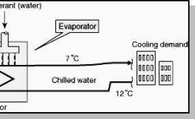
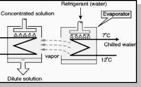
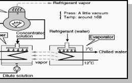
102 5.6 Vapour Absorption Refrigeration Evaporator Absorber High pressure generator 94

103 Condenser Evaporative Cooling Air in contact with water to cool it close to wet bulb temperature Advantage: efficient cooling at low cost Disadvantage: air is rich in moisture 5.7 COMPARISON BETWEEN VAPOR COMPRESSION AND ABSORPTION SYSTEM 5.8 PERFORMANCE Assessment of Refrigeration Cooling effect: Tons of Refrigeration 1 TR = 3024 kcal/ /hr heat rejected TR is assessed as: TR = Q x Cp x (Ti To) /
104 Q = mass flow rate of coolant in kg/hr Cp = is coolant specific heat in kcal /kg C Ti = inlet, temperature of coolant to evaporator (chiller) in 0 C To = outlet temperature of coolant from evaporator (chiller) in 0 C Specific Power Consumption (kw/tr) Indicator of refrigeration system s performance kw/tr of centralized chilled water system is sum of Compressor kw/tr Chilled water pump kw/tr Condenser water pump kw/tr Cooling tower fan kw/tr Coefficient of Performance (COP) The performance of refrigerators and heat pumps is expressed in terms of coefficient of performance (COP), defined as Measure Airflow Q (m3/s) at Fan Coil Units (FCU) or Air Handling Units (AHU): anemometer Air density (kg/m3) Dry bulb and wet bulb temperature: psychrometer Enthalpy (kcal/kg) of inlet air (h in ) and outlet air (H out ): psychrometric charts 5.9 APPLICATIONS OF REFRIGERATRION Metal workers Oil refineries Chemical plants Petrochemical plants Transporting temperature-sensitive foodstuffs Dairy products 96
105 AIR CONDITIONERS 5.10 CONCEPT OF AIR CONDITIONING Air conditioning (often referred to as aircon, AC or A/C) is the process of altering the properties of air (primarily temperatureand humidity) to more favourable conditions, typically with the aim of distributing the conditioned air to an occupied space to improve thermal comfort and indoor air quality TYPES OF AIR CONDITIONERS Room air conditioners Zoned Systems Unitary Systems Window Air-conditioning System Split Air-conditioning System Central air conditioning systems ROOM AIR CONDITIONER Room air conditioners cool rooms rather than the entire home. Less expensive to operate than central units Their efficiency is generally lower than that of central air conditioners. Can be plugged into any 15- or 20-amp, 115-volt household circuit that is not shared with any other major appliances ZONED SYSTEMS CENTRAL AIR CONDITIONING Circulate cool air through a system of supply and return ducts. Supply ducts and registers (i.e., openings in the walls, floors, or ceilings covered by grills) carry cooled air from the air conditioner to the home. This cooled air becomes warmer as it circulates through the home; then it flows back to the central air conditioner through return ducts and registers 97
106 UNITARY SYSTEMS A unitary air conditioning system comprises an outdoor unit including a compressor for compressing a refrigerant, an outdoor heat exchanger for heat exchange of the refrigerant and an expander connected to the outdoor heat exchanger, for expanding the refrigerant; a duct installed inside a zone of a building; a central blower unit having a heat exchanger connected to the outdoor unit through a first refrigerant pipe and a blower for supplying the air heat-exchanged by the heat exchanger to the duct; and an individual blower unit including a heat exchanger connected to the outdoor unit through a second refrigerant pipe and a fan for sending the air heat exchanged by the heat exchanger and disposed in a zone in the building, for individually cooling or heating the zone. Accordingly, cooling or heating operation is performed on each zone of the building, and simultaneously, additional individual heating or cooling operation can be performed on a specific space, so that a cost can be reduced and cooling or heating in the building can be efficiently performed WINDOW AIR-CONDITIONING SYSTEM It is the most commonly used air conditioner for single rooms. In this air conditioner all the components, namely the compressor, condenser, expansion valve or coil, evaporator and cooling coil are enclosed in a single box. This unit is fitted in a slot made in the wall of the room, or often a window sill. Windows air conditioners are one of the most widely used types of air conditioners because they are the simplest form of the air conditioning systems. Window air conditioner comprises of the rigid base on which all 98

107 the parts of the window air conditioner are assembled. The base is assembled inside the casing which is fitted into the wall or the window of the room in which the air conditioner is fitted. The whole assembly of the window air conditioner can be divided into two compartments: the room side, which is also the cooling side and the outdoor side from where the heat absorbed by the room air is liberated to the atmosphere. The room side and outdoor side are separated from each other by an insulated partition enclosed inside the window air conditioner assembly. In the front of the window air conditioner on the room side there is beautifully decorated front panel on which the supply and return air grills are fitted (the whole front panel itself is commonly called as front grill). The louvers fitted in the supply air grills are adjustable so as to supply the air in desired direction. There is also one opening in the grill that allows access to the Control panel or operating panel in front of the window air conditioner. TYPES OF CENTRAL AC split-system An outdoor metal cabinet contains the condenser and compressor, and an indoor cabinet contains the evaporator Packaged The evaporator, condenser, and compressor are all located in one cabinet SPLIT AIR-CONDITIONING SYSTEM: The split air conditioner comprises of two parts: the outdoor unit and the indoor unit. The outdoor unit, fitted outside the room, houses components like the compressor, condenser and expansion valve. The indoor unit comprises the evaporator or cooling 99
 of heat they can remove per hour.")
108 coil and the cooling fan. For this unit you don't have to make any slot in the wall of the room. Further, the present day split units have aesthetic looks and add to the beauty of the room. The split air conditioner can be used to cool one or two rooms. Energy Consumption Air conditioners are rated by the number of British Thermal Units (Btu) of heat they can remove per hour. Another common rating term for air conditioning size is the "ton," which is 12,000 Btu per hour. Room air conditioners range from 5,500 Btu per hour to 14,000 Btu per hour. Energy Efficiency Today's best air conditioners use 30% to 50% less energy than 1970s Even if your air conditioner is only 10 years old, you may save 20% to 40% of your cooling energy costs by replacing it with a newer, more efficient model 100
109 5.12 SOLVED PROBLEMS 1. A sling psychrometer gives reading of 25 0 c dry bulb temperature 15 0 c wet bulb temperature. The barometer indicates 760 mm of hg assuming partial pressure of the vapour as 10 mm of Hg. Determine 1. Specific humidity 2. Saturation ratio. Given Data: Dry bulb temperature td =25 0 c Wet bulb temperature tw=15 0 c Barometer pressure pb=760mm of Hg Partial pressure pv= 10mm of Hg To Find: Specific humidity Saturation ratio. Solution: Specific humidity: We know that Specific humidity W = Saturation ratio: kg/kg of dry air From steam table corresponding to dry bulb temperature td =25 0 c We find the partial pressure ps= bar = =23.8 mm of Hg 101
110 We know that Saturation ratio. µ= = = 0.41 Result: 1. Specific humidity kg/kg of dry air 2. Saturation ratio. = A two stages, single acting air compressor compresses air to 20bar. The air enters the L.P cylinder at 1bar and 27 o c and leaves it at 4.7bar. the air enters the H.P. cylinder at 4.5bar and 27 o c. the size of the L.P cylinder is 400mm diameter and 500mm stroke. The clearance volume In both cylinder is 4% of the respective stroke volume. The compressor runs at 200rpm, taking index of compression and expansion in the two cylinders as 1.3, estimatee 1. The indicated power required to run the compressor; and 2. The heat rejected in the intercooler per minute. Given data: Pressure (P4)= 20bar Pressure (P1) = 1bar = N/m 2 Temperature (T1) = 27 o C = = 300K Pressure (P2) = 4.7bar Pressure (P3) = 4.5bar Temperature (T3) = 27 o C = = 300K Diameter (D1) = 400mm 0.4m Stroke (L1) = 500mm 0mm = 0.5m N = 200rpm ; n = 1.3 To Find: Indicated power required to run the compressor Solution : 102
111 We know the swept volume of the L.P cylinder = m 3 And volumetric efficiency, ηv = or 90.85% Volume of air sucked by air pressure compressor, =1.42 m 3 /min And volume of air sucked by H.P compressor, We know that indicated work done by L.P compressor = J/min = KJ/min And indicated workdone by H.P compressor, 103
112 = J/min = KJ/min Total indicated work done by the compressor, W = WL + WH = = KJ/min Indicated power required to run the compressor = / 60 = 69.3KW 3. In an oil gas turbine installation ation, air is taken as 1 bar and 30 o C. The air is compressed to 4bar and then heated by burning the oil to a temperature of 500 o C. If the air flows at the rate of 90Kg/min. Find the power developed by the plant take γ for air as 1.4 Cp as 1KJ/KgK. If 2.4Kg of oil having calorific value of 40,000 KJ/Kg if burned in the combustion chamber per minute. Find the overall efficiency of the plant. Given Data: Pressure (P4 = P3) = 1bar Pressure (P1 = P2) = 4bar Temperature (T2) = 500 o C = = 773K Mass flow rate of air(ma) = 90Kg/min = 1.5Kg/sec Mass flow rate of fuel (mf) = 2.4Kg/min = 0.04Kg/sec Temperature (T4) = 30 o C = = 303K γ = 1.4 ; Cp = 1KJ/KgK ; Cv= 40,000 KJ/Kg To Find: Power developeded by the plant Performance of the gas turbine Overall efficiency of the plant Solution: 104
113 Power developed by the plant: Let T1,T3 T3 = temperature of air at points 1 and3 Weknow that isentropic expansion 2-3, T3 = T = = 520K Similarly for isentropic compression 4-1: T1 1 = T4/ = 303/0.673 = 450K Performance of the gas turbine: We know that work developed by the turbine, = 379.5KJ/s And work developed by the compressor, = 220.5/s Net work or power of the turbine, P = WT - Wc = = 159KJ/s = 159KW Overall efficiency of the plant: We know that the heat supplied per second = mf C = ,000 = 1600 KJ/s Therefore, overall efficiency of the plant, ηo = 159/1600 = or 9.99% 105
114 5.13 TECHNICAL TERMS BTU - British thermal unit. A unit of heat energy - approximately the amount of energy needed to heat one pound of water by one degree Fahrenheit. dba a unit for measuring sound power or pressure, decibel on the A scale. Capacity the ability of a heating or cooling system to heat or cool a given amount of space. For heating, this is usually expressed in BTU s. For cooling, it is usually given in tons. Compressor the pump that moves the refrigerant from the indoor evaporator to the outdoor condenser and back to the evaporator again. The compressor is often called the heart of the system because it circulates the refrigerant through the loop. Condenser a device used to condense a refrigerant thereby rejecting the heat to another source, typically an air cooled or water cooled condenser. Cassette a fan coil unit that fits mainly in the ceiling void with only a diffuser plate visible, diffuses conditioned air in one, two, three or four directions. HVAC heating, ventilation and air conditioning. Inverter system Constantly alters fan and motor speeds. This enables faster cooling of a room, and the inverter air conditioner doesn t have to switch itself on and off to maintain a constant temperature. kw standard measurement of heat or power, 1kw = 1000 watts = 3412Btu/hr = 860kcal. Load Calculation a mathematical design tool used to determine the heat gain and heat loss in a building so that properly sized air conditioning and heating equipment may be installed. Refrigerant a substance that produces a refrigerating effect while expanding or vaporizing. Reverse cycle the reverse cycle air conditioner internally reverses its operation to provide heating or cooling, as required. Split System a central air conditioner consisting of two or more major components. The system usually consists of a compressor-containing unit and condenser, installed outside the building and a non-compressor containing air handling unit installed within the building. This is the most common type of system installed in a home. Zoning the practice of providing independent heating and/or cooling to different areas in a structure. Zoning typically utilizes a system controller, zoning dampers controlled by a thermostat in each zone, and a bypass damper to regulate static pressure in the supply duct. 106
115 5.15 REVIEW QUESTIONS PART A 1. What is the function of analyzer and rectifier in an absorption system? 2. Define by-pass factor. 3. Give examples for positive displacement compressor. 4. What is meant by subcooling in vapour compression system? 5. What is the advantage of multi stage air compressor? 6. Define dew point temperature 7. Define tons of refrigeration and COP. 8. What is the difference between air conditioning and refrigeration? 9. What are the effect of superheat and subcooling on the vapor compression cycle? 10. What are the properties of good refrigerant? 11. Define RSHF,RTH. 12. Name four important properties of a good refrigerant 13. What is the difference between air conditioning and refrigeration. 14. What is the function of the throttling valve in vapour compression refrigeration system? 15. In a vapour compression refrigeration system, where the highest temperature will occur? 16. The vapour absorption system can use low-grade heat energy in the generator. Is true of false? 17. Name any four commonly used refrigerants. 18. Explain unit of Refrigeration. 19. Why throttle valve is used in place of expansion cylinder for vapour compression refrigerant machine. 20. What are the effect pf super heat and suhcooling on.the vapour compression cycle? 21. What are the properties of good refrigerant? 22. How are air-conditioning systems classified? 23. How does humidity affect human comfort? 24. What are the various sources of heat gain of an air-conditioned space? 25. What do you mean by the term infiltration in heat load calculations? PART B 1. Draw neat sketch of simple vapor compression refrigeration system and explain. 2. Explain with sketch the working principle of aqua Ammonia refrigeration system. 3. Explain with sketch the working principle of water-lithium bromide refrigeration system. 4. Briefly explain the cooling load calculation in air conditioning system. 5. Explain winter, summer, and year round Alc system. 6. Explain unitary Alc and central Alc system. 7. Explain any four psychometric processes with sketch. 8. A refrigeration system of 10.5 tonnes capacity at an evaporator temperature of -12 C and a condenser temperature of 27 C is needed in a food storage locker. The refrigerant Ammonia is sub cooled by 6 C before entering the expansion valve. The compression in the compressor is of adiabatic type. Find 1. Condition of vapor at outlet of the compressor.2. Condition of vapor at the entrance of the Evaporator 3.COP &power required. 107
116 9. A sling psychrometer in a lab test recorded the following readings DBT=35 C, WBT=25 CCalculate the following 1. Specific humidity 2. Relative humidity 3. Vapor density in air 4. Dew point temperature 5. Enthalpy of mixing per kg of air.take atmospheric pressure= bar. 108
117
118
119
120
121
122
123
124
125
126
127
128
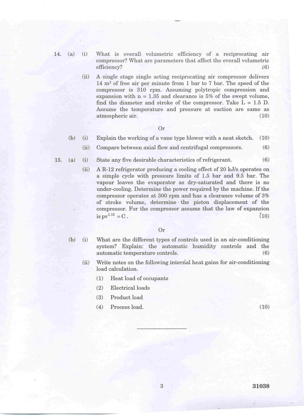
129
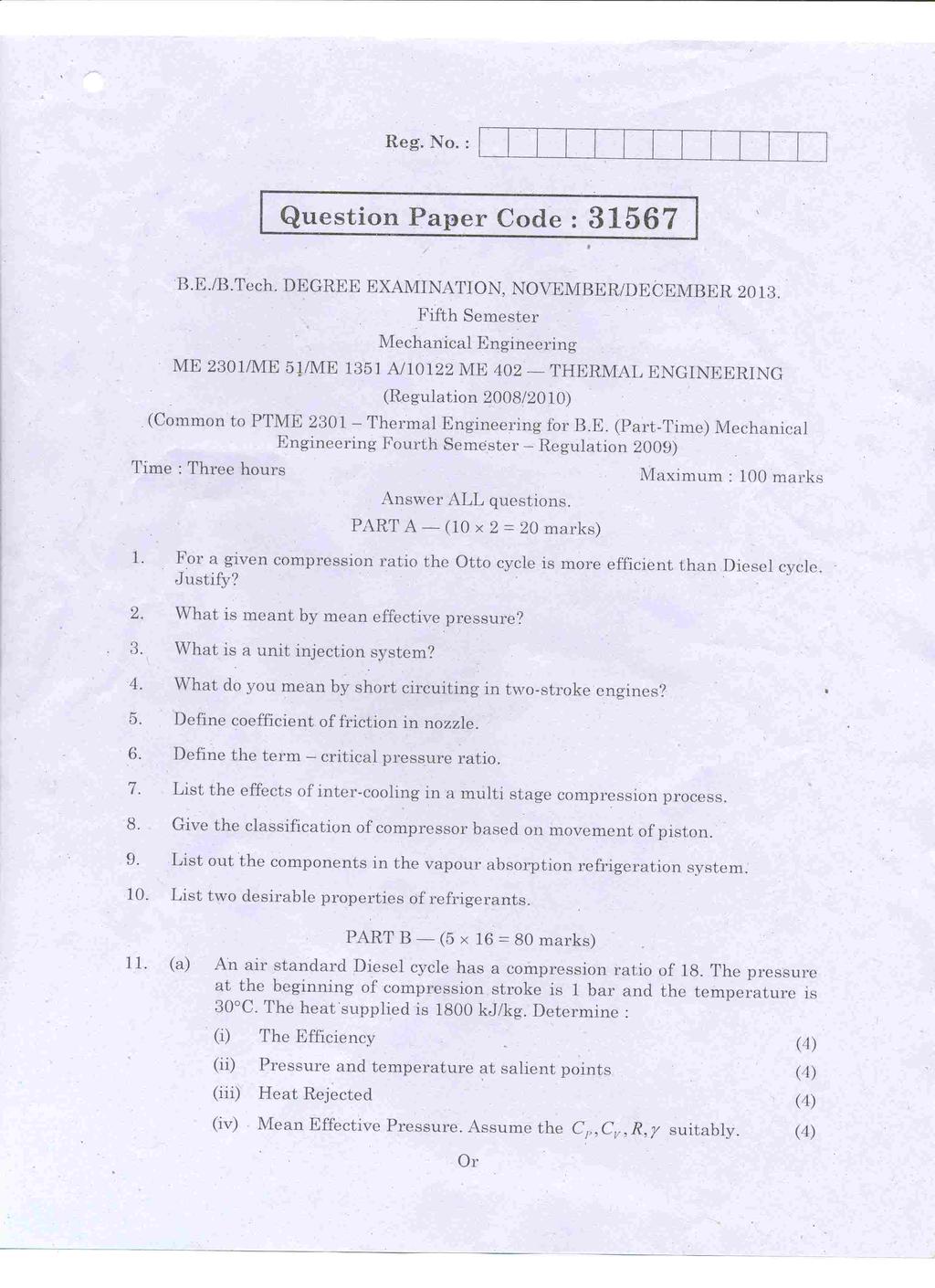
130
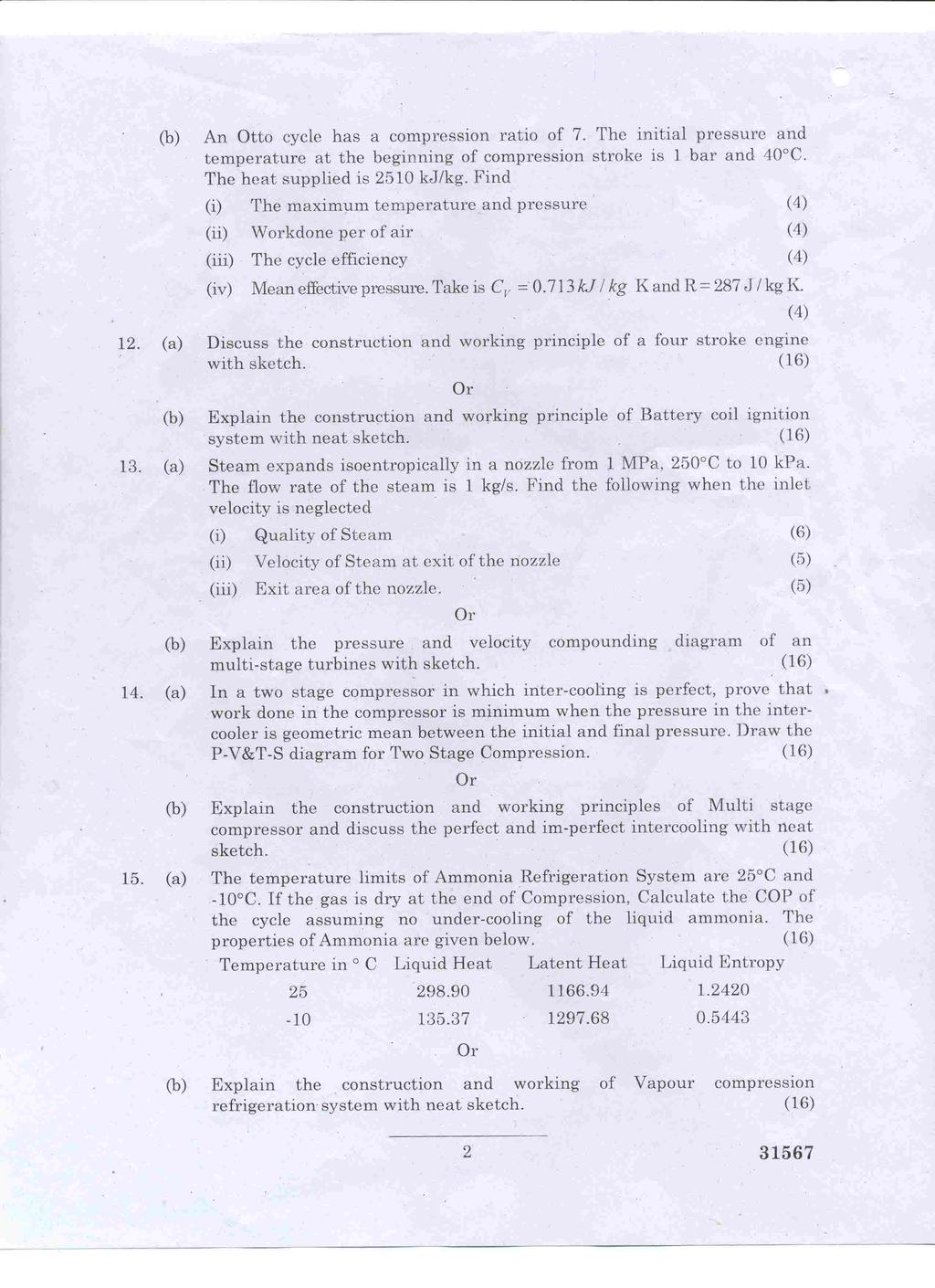
131
ME2301 THERMAL ENGINEERING L T P C OBJECTIVE:
 ME2301 THERMAL ENGINEERING L T P C 3 1 0 4 OBJECTIVE: To integrate the concepts, laws and methodologies from the first course in thermo dynamics into analysis of cyclic processes To apply the thermodynamic
UNIT IV INTERNAL COMBUSTION ENGINES
 UNIT IV INTERNAL COMBUSTION ENGINES Objectives After the completion of this chapter, Students 1. To know the different parts of IC engines and their functions. 2. To understand the working principle of
04. Ignition and Exhaust system
 New Polytechnic Kolhapur Page 1 of 10 04. Ignition and Exhaust system 4.1 Introduction to Ignition System 4 Marks Requirements of ignition system. Magneto and Battery Ignition systems (Working only). Firing
Study of cooling, lubrication and ignition system in diesel and petrol engines.
 Study of cooling, lubrication and ignition system in diesel and petrol engines. Aim: - To study the conventional battery ignition system Construction: The function of battery ignition system is to produce
SAMPLE STUDY MATERIAL
 IC Engine - ME GATE, IES, PSU 1 SAMPLE STUDY MATERIAL Mechanical Engineering ME Postal Correspondence Course Internal Combustion Engine GATE, IES & PSUs IC Engine - ME GATE, IES, PSU 2 C O N T E N T 1.
VALVE TIMING DIAGRAM FOR SI ENGINE VALVE TIMING DIAGRAM FOR CI ENGINE
 VALVE TIMING DIAGRAM FOR SI ENGINE VALVE TIMING DIAGRAM FOR CI ENGINE Page 1 of 13 EFFECT OF VALVE TIMING DIAGRAM ON VOLUMETRIC EFFICIENCY: Qu. 1:Why Inlet valve is closed after the Bottom Dead Centre
UNIT 4 IGNITION SYSTEMS
 UNIT 4 IGNITION SYSTEMS Ignition Systems Structure 4.1 Introduction Objectives 4.2 Ignition System Types 4.3 Comparison between Battery and Magneto Ignition System 4.4 Drawbacks (Disadvantages) of Conventional
UNIT 2 POWER PLANTS 2.1 INTRODUCTION 2.2 CLASSIFICATION OF IC ENGINES. Objectives. Structure. 2.1 Introduction
 UNIT 2 POWER PLANTS Power Plants Structure 2.1 Introduction Objectives 2.2 Classification of IC Engines 2.3 Four Stroke Engines versus Two Stroke Engines 2.4 Working of Four Stroke Petrol Engine 2.5 Working
(v) Cylinder volume It is the volume of a gas inside the cylinder when the piston is at Bottom Dead Centre (B.D.C) and is denoted by V.
 Cylinder volume It is the volume of a gas inside the cylinder when the piston is at Bottom Dead Centre (B.D.C) and is denoted by V.") UNIT II GAS POWER CYCLES AIR STANDARD CYCLES Air standard cycles are used for comparison of thermal efficiencies of I.C engines. Engines working with air standard cycles are known as air standard engines.
UNIT II GAS POWER CYCLES AIR STANDARD CYCLES Air standard cycles are used for comparison of thermal efficiencies of I.C engines. Engines working with air standard cycles are known as air standard engines.
Internal Combustion Engines
 Internal Combustion Engines The internal combustion engine is an engine in which the burning of a fuel occurs in a confined space called a combustion chamber. This exothermic reaction of a fuel with an
2013 THERMAL ENGINEERING-I
 SET - 1 II B. Tech II Semester, Regular Examinations, April/May 2013 THERMAL ENGINEERING-I (Com. to ME, AME) Time: 3 hours Max. Marks: 75 Answer any FIVE Questions All Questions carry Equal Marks ~~~~~~~~~~~~~~~~~~~~~~~~
KINGS COLLEGE OF ENGINEERING DEPARTMENT OF MECHANICAL ENGINEERING. Question Bank. UNIT-I THERMODYNAMIC CYCLES Part-A (2 Marks)
") KINGS COLLEGE OF ENGINEERING DEPARTMENT OF MECHANICAL ENGINEERING Question Bank Sub. Code/Name: ME1351 - THERMAL ENGINEERING Year/Sem: III/VI 1. What is a thermodynamic cycle? UNIT-I THERMODYNAMIC CYCLES
KINGS COLLEGE OF ENGINEERING DEPARTMENT OF MECHANICAL ENGINEERING Question Bank Sub. Code/Name: ME1351 - THERMAL ENGINEERING Year/Sem: III/VI 1. What is a thermodynamic cycle? UNIT-I THERMODYNAMIC CYCLES
Gas Power Cycles. Tarawneh
 Gas Power Cycles Dr.Mohammad Tarawneh ) Carnot cycle 2) Otto cycle ) Diesel cycle - Today 4) Dual Cycle 5) Stirling cycle 6) Ericsson cycles 7) Brayton cycle Carnot Cycle Reversible isothermal expansion
Combustion engines. Combustion
 Combustion engines Chemical energy in fuel converted to thermal energy by combustion or oxidation Heat engine converts chemical energy into mechanical energy Thermal energy raises temperature and pressure
2. Discuss the effects of the following operating variables on detonation
 Code No: RR220303 Set No. 1 II B.Tech II Semester Regular Examinations, Apr/May 2006 THERMAL ENGINEERING-I ( Common to Mechanical Engineering and Automobile Engineering) Time: 3 hours Max Marks: 80 Answer
(a) then mean effective pressure and the indicated power for each end ; (b) the total indicated power : [16]
![(a) then mean effective pressure and the indicated power for each end ; (b) the total indicated power : [16]](/thumbs/79/80273804.jpg "(a) then mean effective pressure and the indicated power for each end ; (b) the total indicated power : [16]") Code No: R05220304 Set No. 1 II B.Tech II Semester Regular Examinations, Apr/May 2007 THERMAL ENGINEERING-I ( Common to Mechanical Engineering and Automobile Engineering) Time: 3 hours Max Marks: 80 Answer
Code No: R05220304 Set No. 1 II B.Tech II Semester Regular Examinations, Apr/May 2007 THERMAL ENGINEERING-I ( Common to Mechanical Engineering and Automobile Engineering) Time: 3 hours Max Marks: 80 Answer
Assignment-1 Air Standard Cycles
 Assignment-1 Air Standard Cycles 1. What do u mean by air standard cycle? List assumptions for air standard cycle & give reasons why air standard cycle differs from actual cycle. 2. Derive an equation
Comparative Study Of Four Stroke Diesel And Petrol Engine.
 Comparative Study Of Four Stroke Diesel And Petrol Engine. Aim: To study the construction and working of 4- stroke petrol / diesel engine. Theory: A machine or device which derives heat from the combustion
ME2301 THERMAL ENGINEERING L T P C OBJECTIVE: To integrate the concepts, laws and methodologies from the first course in thermo dynamics into
 ME2301 THERMAL ENGINEERING L T P C 3 1 0 4 OBJECTIVE: To integrate the concepts, laws and methodologies from the first course in thermo dynamics into analysis of cyclic processes To apply the thermodynamic
ENGINES ENGINE OPERATION
 ENGINES ENGINE OPERATION Because the most widely used piston engine is the four-stroke cycle type, it will be used as the example for this section, Engine Operation and as the basis for comparison in the
AT AUTOMOTIVE ENGINES QUESTION BANK
 AT6301 - AUTOMOTIVE ENGINES QUESTION BANK UNIT I: CONSTRUCTION & WORKING PRINCIPLE OF IC ENGINES 1. State the application of CI engines? 2. What is Cubic capacity of an engine? 3. What is the purpose of
CHAPTER I GAS POWER CYCLES
 CHAPTER I GAS POWER CYCLES 1.1 AIR STANDARD CYCLES Air standard cycles are used for comparison of thermal efficiencies of I.C engines. Engines working with air standard cycles are known as air standard
USO4CICV01/US04CICH02:
 Natubhai V. Patel College of Pure & Applied Sciences S. Y. B.Sc. Semester-4 Industrial chemistry/ IC (Vocational) USO4CICV0/US04CICH02: Chemical Plant Utilities UNIT 5 Internal combustion engine In an
Chapter 8 Production of Power from Heat
 Chapter 8 Production of Power from Heat Different sources of power, such as solar energy (from sun), kinetic energy from atmospheric winds and potential energy from tides. The most important source of
ENGINE & WORKING PRINCIPLES
 ENGINE & WORKING PRINCIPLES A heat engine is a machine, which converts heat energy into mechanical energy. The combustion of fuel such as coal, petrol, diesel generates heat. This heat is supplied to a
INTERNAL COMBUSTION ENGINE (SKMM 4413)
") INTERNAL COMBUSTION ENGINE (SKMM 4413) Dr. Mohd Farid bin Muhamad Said Room : Block P21, Level 1, Automotive Development Centre (ADC) Tel : 07-5535449 Email: mfarid@fkm.utm.my HISTORY OF ICE History of
INTERNAL COMBUSTION ENGINE (SKMM 4413) Dr. Mohd Farid bin Muhamad Said Room : Block P21, Level 1, Automotive Development Centre (ADC) Tel : 07-5535449 Email: mfarid@fkm.utm.my HISTORY OF ICE History of
Chapter 9 GAS POWER CYCLES
 Thermodynamics: An Engineering Approach, 6 th Edition Yunus A. Cengel, Michael A. Boles McGraw-Hill, 2008 Chapter 9 GAS POWER CYCLES Copyright The McGraw-Hill Companies, Inc. Permission required for reproduction
DEPARTMENT OF MECHANICAL ENGINEERING Question Bank ME THERMAL ENGINEERING. Part-A (2 Marks)
") DEPARTMENT OF MECHANICAL ENGINEERING Question Bank ME1351 - THERMAL ENGINEERING UNIT I GAS POWER CYCLES Part-A (2 Marks) 1. What is a thermodynamic cycle? 2. What is meant by air standard cycle? 3.. Name
DEPARTMENT OF MECHANICAL ENGINEERING Question Bank ME1351 - THERMAL ENGINEERING UNIT I GAS POWER CYCLES Part-A (2 Marks) 1. What is a thermodynamic cycle? 2. What is meant by air standard cycle? 3.. Name
Engine Cycles. T Alrayyes
 Engine Cycles T Alrayyes Introduction The cycle experienced in the cylinder of an internal combustion engine is very complex. The cycle in SI and diesel engine were discussed in detail in the previous
VETRI VINAYAHA COLLEGE OF ENGINEERING AND TECHNOLOGY DEPARTMENT OF MECHANICAL ENGINEERING ME6404 THERMAL ENGINEERING
 VETRI VINAYAHA COLLEGE OF ENGINEERING AND TECHNOLOGY DEPARTMENT OF MECHANICAL ENGINEERING ME6404 THERMAL ENGINEERING UNIT I - GAS POWER CYCLES 1. What is a thermodynamic cycle? Thermodynamic cycle is defined
Chapter 9 GAS POWER CYCLES
 Thermodynamics: An Engineering Approach Seventh Edition in SI Units Yunus A. Cengel, Michael A. Boles McGraw-Hill, 2011 Chapter 9 GAS POWER CYCLES Mehmet Kanoglu University of Gaziantep Copyright The McGraw-Hill
L34: Internal Combustion Engine Cycles: Otto, Diesel, and Dual or Gas Power Cycles Introduction to Gas Cycles Definitions
 Page L: Internal Combustion Engine Cycles: Otto, Diesel, and Dual or Gas Power Cycles Review of Carnot Power Cycle (gas version) Air-Standard Cycles Internal Combustion (IC) Engines - Otto and Diesel Cycles
OBJECTIVE: GENERAL ASPECTS ABOUT ENGINES MECHANISM:
 LANDMARK UNIVERSITY, OMU-ARAN LECTURE NOTE 3 COLLEGE: COLLEGE OF SCIENCE AND ENGINEERING DEPARTMENT: MECHANICAL ENGINEERING Course code: MCE 211 Course title: Introduction to Mechanical Engineering Credit
UNIT 1 GAS POWER CYCLES
 THERMAL ENGINEERING UNIT 1 GAS POWER CYCLES Air Standard Cycles - Otto, Diesel, Dual, Brayton cycle with intercooling, reheating and regeneration- Calculation of airstandard efficiency and mean effective
Assignment-1 Introduction
 Assignment-1 Introduction 1. Compare S.I. engines with C.I engines. 2. Explain with the help of neat sketch, the working of a 2-stroke petrol engine. 3. Derive an equation of efficiency, work output and
Class Notes on Thermal Energy Conversion System
 Class Notes on Thermal Energy Conversion System For the students of Civil & Rural 3 rd semester Ramesh Khanal Assistant Professorr Nepal Engineering College Bhaktapur, Nepal 2015 Course Structure MEC 209.3:
Internal combustion engines can be classified in a number of different ways: 1. Types of Ignition
 Chapter 1 Introduction 1-3 ENGINE CLASSIFICATIONS Internal combustion engines can be classified in a number of different ways: 1. Types of Ignition 1 (a) Spark Ignition (SI). An SI engine starts the combustion
In this lecture... Gas power cycles
 7 Lect-7 Gas power cycles In this lecture... he Carnot cycle and its significance Air-standard assumptions An oeriew of reciprocating engines Otto cycle: the ideal cycle for sparkignition engines Diesel
 SET - 1 II B. Tech II Semester Regular/Supplementary Examinations, April/May-2017 THERMAL ENGINEERING-I (Mechanical Engineering) Time: 3 hours Max. Marks: 70 Note: 1. Question Paper consists of two parts
Chapter 14 Small Gas Engines
 Chapter 14 Small Gas Engines Use the Textbook Pages 321 349 to help answer the questions Why You Learn So Well in Tech & Engineering Classes 1. Internal combustion make heat by burning a fuel & air mixture
UNIT I GAS POWER CYCLES
 UNIT I GAS POWER CYCLES The Otto Cycle The Otto cycle, which was first proposed by a Frenchman, Beau de Rochas in 1862, was first used on an engine built by a German, Nicholas A. Otto, in 1876. The cycle
Internal Combustion Engine. Prepared by- Md Ferdous Alam Lecturer, MEE, SUST
 Internal Combustion Engine Prepared by- Md Ferdous Alam Lecturer, MEE, SUST What is an Engine? -a machine designed to convert one form of energy into mechanical energy Two types of engines : 1. Internal
Prepared by: Dr. Assim Adaraje
 Air-standard cycles Prepared by: Dr. Assim Adaraje CH. 2 ۱ Cold-air-standard assumptions: When the working fluid is considered to be air with constant specific heats at room temperature (25 C). Air-standard
Chapter 6. Supercharging
 SHROFF S. R. ROTARY INSTITUTE OF CHEMICAL TECHNOLOGY (SRICT) DEPARTMENT OF MECHANICAL ENGINEERING. Chapter 6. Supercharging Subject: Internal Combustion Engine 1 Outline Chapter 6. Supercharging 6.1 Need
Idealizations Help Manage Analysis of Complex Processes
 8 CHAPTER Gas Power Cycles 8-1 Idealizations Help Manage Analysis of Complex Processes The analysis of many complex processes can be reduced to a manageable level by utilizing some idealizations (fig.
ME Thermal Engineering Question Bank
 ME2301 - Thermal Engineering Question Bank UNIT I GAS POWER CYCLES Otto, Diesel, Dual, Brayton cycles, Calculation of mean effective pressure, and air standard efficiency -Actual and theoretical PV diagram
Thermodynamics cycles can be classified into different categories depending on fluid used or the different processes:
 Classification of thermodynamics cycles Thermodynamics cycles can be classified into different categories depending on fluid used or the different processes: Gas and vapor cycles - Gas cycle: the working
I.C ENGINES. CLASSIFICATION I.C Engines are classified according to:
 I.C ENGINES An internal combustion engine is most popularly known as I.C. engine, is a heat engine which converts the heat energy released by the combustion of the fuel taking place inside the engine cylinder
ADDIS ABABA UNIVERSITY INSTITUTE OF TECHNOLOGY
 1 INTERNAL COMBUSTION ENGINES ADDIS ABABA UNIVERSITY INSTITUTE OF TECHNOLOGY MECHANICAL ENGINEERING DEPARTMENT DIVISON OF THERMAL AND ENERGY CONVERSION IC Engine Fundamentals 2 Engine Systems An engine
Introduction to I.C Engines CH. 1. Prepared by: Dr. Assim Adaraje
 Introduction to I.C Engines CH. 1 Prepared by: Dr. Assim Adaraje 1 An internal combustion engine (ICE) is a heat engine where the combustion of a fuel occurs with an oxidizer (usually air) in a combustion
SIDDHARTH INSTITUTE OF ENGINEERING & TECHNOLOGY :: PUTTUR (AUTONOMOUS) QUESTION BANK UNIT I I.C ENGINES
 QUESTION BANK UNIT I I.C ENGINES") SIDDHARTH INSTITUTE OF ENGINEERING & TECHNOLOGY :: PUTTUR UNIT I I.C ENGINES 1 (a) Explain any six types of classification of Internal Combustion engines. (6M) (b) With a neat sketch explain any three
SIDDHARTH INSTITUTE OF ENGINEERING & TECHNOLOGY :: PUTTUR UNIT I I.C ENGINES 1 (a) Explain any six types of classification of Internal Combustion engines. (6M) (b) With a neat sketch explain any three
η th W = Q Gas Power Cycles: Working fluid remains in the gaseous state through the cycle.
 Gas Power Cycles: Gas Power Cycles: Working fluid remains in the gaseous state through the cycle. Sometimes useful to study an idealised cycle in which internal irreversibilities and complexities are
Power Cycles. Ideal Cycles, Internal Combustion
 Gas Power Cycles Power Cycles Ideal Cycles, Internal Combustion Otto cycle, spark ignition Diesel cycle, compression ignition Sterling & Ericsson cycles Brayton cycles Jet-propulsion cycle Ideal Cycles,
Principles of Engine Operation. Information
 Internal Combustion Engines MAK 4070E Principles of Engine Operation Prof.Dr. Cem Soruşbay Istanbul Technical University Information Prof.Dr. Cem Soruşbay İ.T.Ü. Makina Fakültesi Motorlar ve Taşıtlar Laboratuvarı
Powertrain Efficiency Technologies. Turbochargers
 Powertrain Efficiency Technologies Turbochargers Turbochargers increasingly are being used by automakers to make it possible to use downsized gasoline engines that consume less fuel but still deliver the
IC ENGINES. Differences between SI and CI engines: Petrol is fuel, which has a high self ignition temperature
 IC ENGINES SI Engines work at constant volume. They have a compression ratio of around 6-10. But CI engines work at constant pressure and has a compression ratio of 16-20. In four stroke engines, one power
ACTUAL CYCLE. Actual engine cycle
 1 ACTUAL CYCLE Actual engine cycle Introduction 2 Ideal Gas Cycle (Air Standard Cycle) Idealized processes Idealize working Fluid Fuel-Air Cycle Idealized Processes Accurate Working Fluid Model Actual
Heat Transfer in Engines. Internal Combustion Engines
 Heat Transfer in Engines Internal Combustion Engines Energy Distribution Removing heat is critical in keeping an engine and lubricant from thermal failure Amount of energy available for use: Brake thermal
Fundamentals of Small Gas Engines
 Fundamentals of Small Gas Engines Objectives: Describe the four-stroke cycle engine operation and explain the purpose of each stroke Explain the concept of valve timing Describe two-stroke engine operation
Kul Internal Combustion Engine Technology. Definition & Classification, Characteristics 2015 Basshuysen 1,2,3,4,5
 Kul-14.4100 Internal Combustion Engine Technology Definition & Classification, Characteristics 2015 Basshuysen 1,2,3,4,5 Definitions Combustion engines convert the chemical energy of fuel to mechanical
A. Aluminum alloy Aluminum that has other metals mixed with it.
 ENGINE REPAIR UNIT 1: ENGINE DESIGN LESSON 1: PRINCIPLES OF ENGINE DESIGN I. Terms and definitions A. Aluminum alloy Aluminum that has other metals mixed with it. B. Bearing A device that allows movement
CONCEPTUAL DESIGN OF A NEW TYPE OF ENGINE FOR VARIOUS APPLICATIONS WITH EXPECTED 10% HIGHER OVERALL EFFICIENCY
 International Journal of Mechanical and Production Engineering Research and Development (IJMPERD ) Vol.1, Issue 2 Dec 2011 58-65 TJPRC Pvt. Ltd., CONCEPTUAL DESIGN OF A NEW TYPE OF ENGINE FOR VARIOUS APPLICATIONS
TKP3501 Farm Mechanization
 TKP3501 Farm Mechanization Topic 2: Internal Combustion Engines Ahmad Suhaizi, Mat Su Email: asuhaizi@upm.edu.my Outlines Internal vs external combustion engines Engine structure Combustion cycle 4 stroke
Approved by AICTE, Government of India & affiliated to Dr. A.P.J. Abdul Kalam Technical University, Lucknow Department of Mechanical Engineering
 Experiment No. - 1 Object: Study and working of four stroke petrol engine. Apparatus Required: S. No. Name of Apparatus Specifications Model of Four stroke petrol engine NA Figure 1: Working of four stroke
Chapter 4 ANALYTICAL WORK: COMBUSTION MODELING
 a 4.3.4 Effect of various parameters on combustion in IC engines: Compression ratio: A higher compression ratio increases the pressure and temperature of the working mixture which reduce the initial preparation
UNIT-IV IC ENGINES AIR CONDITIONING
 UNIT-IV IC ENGINES & AIR CONDITIONING UNIT-IV INTERNAL COMBUSTION ENGINES&AIR CONDITIONING SYSTEMS 1. Explain Psychometric Properties. The properties of dry air and water vapor mixture are known as psychometric
2) Rich mixture: A mixture which contains less air than the stoichiometric requirement is called a rich mixture (ex. A/F ratio: 12:1, 10:1 etc.
 Rich mixture: A mixture which contains less air than the stoichiometric requirement is called a rich mixture (ex. A/F ratio: 12:1, 10:1 etc.") Unit 3. Carburettor University Questions: 1. Describe with suitable sketches : Main metering system and Idling system 2. Draw the neat sketch of a simple carburettor and explain its working. What are the
Unit 3. Carburettor University Questions: 1. Describe with suitable sketches : Main metering system and Idling system 2. Draw the neat sketch of a simple carburettor and explain its working. What are the
Week 10. Gas Power Cycles. ME 300 Thermodynamics II 1
 Week 10 Gas Power Cycles ME 300 Thermodynamics II 1 Today s Outline Gas power cycles Internal combustion engines Four-stroke cycle Thermodynamic cycles Ideal cycle ME 300 Thermodynamics II 2 Gas Power
SWIRL MEASURING EQUIPMENT FOR DIRECT INJECTION DIESEL ENGINE
 SWIRL MEASURING EQUIPMENT FOR DIRECT INJECTION DIESEL ENGINE G.S.Gosavi 1, R.B.Solankar 2, A.R.Kori 3, R.B.Chavan 4, S.P.Shinde 5 1,2,3,4,5 Mechanical Engineering Department, Shivaji University, (India)
UNIVERSITY POLYTECHNIC B.I.T., MESRA, RANCHI COURSE STRUCTURE. (W.E.F Batch Students) (Total Unit 7.5) Sessional Unit Code
 (Total Unit 7.5) Sessional Unit Code") COURSE STRUCTURE (W.E.F. 2011 Batch Students) (Total Unit 7.5) Course Theory Unit Course Sessional Unit Code Code DAE 4001 Thermal Engineering 1.0 DAE 4002 Thermal Engineering Lab. 0.5 DAE 4003 Fluid Mechanics
COURSE STRUCTURE (W.E.F. 2011 Batch Students) (Total Unit 7.5) Course Theory Unit Course Sessional Unit Code Code DAE 4001 Thermal Engineering 1.0 DAE 4002 Thermal Engineering Lab. 0.5 DAE 4003 Fluid Mechanics
Diesel Engine Power Plants
 Diesel Engine Power Plants Energy Conversion Engineering Diesel Engine Power Plants Introduction Diesel electric plants are generally available in the range of 2 to 50 MW capacity and they can be used
MEB THERMAL ENGINEERING - I QUESTION BANK UNIT-I PART-A
 MEB 420 - THERMAL ENGINEERING - I QUESTION BANK UNIT-I Each question carries 1 mark. PART-A 1. Define temperature. 2. Define intensive property 3. Explain the term absolute zero of temperature 4. State
Template for the Storyboard stage
 Template for the Storyboard stage Animation can be done in JAVA 2-D. Mention what will be your animation medium: 2D or 3D Mention the software to be used for animation development: JAVA, Flash, Blender,
GASOLINE DIRECT INJECTION IN SI ENGINES B. PAVAN VISWANADH P. ASHOK KUMAR. Mobile No : Mobile No:
 GASOLINE DIRECT INJECTION IN SI ENGINES SUBMIT TED BY B. PAVAN VISWANADH P. ASHOK KUMAR Y06ME011, III/IV B. Tech Y06ME003, III/IV B. Tech Pavan.visu@gmail.com ashok.me003@gmail.com Mobile No :9291323516
Chapter 9. Two important areas of application for thermodynamics GAS POWER CYCLES. Objectives
 Chapter 9 GAS POWER CYCLES Two important areas of application for thermodynamics are power generation and refrigeration. Both are usually accomplished by systems that operate on a thermodynamic cycle.
Noble Group of Institutions, Junagadh. Faculty of Engineering Department of Mechanical Engineering
 Semester:1 st Subject: Elements of Mechanical Engineering (2110006) Faculty: Mr. Ishan Bhatt Year: 2017-18 Class: Comp. & IT Ele TUTORIAL 1 INTRODUCTION Q.1 Define: Force, Work, Pressure, Energy, Heat
DEPARTMENT OF MECHANICAL ENGINEERING ME ENGINEERING THERMODYNAMICS TWO MARKS QUESTION AND ANSWER
 DEPARTMENT OF MECHANICAL ENGINEERING ME 6301- ENGINEERING THERMODYNAMICS TWO MARKS QUESTION AND ANSWER 1. Define the term thermal engineering. Ans: Thermal engineering is the science that deals with the
Content : 4.1 Brayton cycle-p.v. diagram and thermal efficiency. 4Marks Classification of gas turbines.
 Content : 4.1 Brayton cycle-p.v. diagram and thermal efficiency. 4Marks Classification of gas turbines. 4.2 Construction and working of gas turbines i) Open cycle ii) Closed cycle gas Turbines, P.V. and
Hours / 100 Marks Seat No.
 17529 14115 3 Hours / 100 Seat No. Instructions (1) All Questions are Compulsory. (2) Answer each next main Question on a new page. (3) Illustrate your answers with neat sketches wherever necessary. (4)
Internal Combustion Engines.
 Internal Combustion Engines. Here's a quick description of a typical internal combustion engine, along with basic vocabularies that describe the components and their functions. This stuffs serve as a quick
CHAPTER 3 ENGINE TYPES
 CHAPTER 3 CHAPTER 3 ENGINE TYPES CONTENTS PAGE Multi-Cylinders 02 Firing orders 06 2 Stroke Cycle 08 Diesel Cycle 10 Wankel Engine 12 Radial/Rotary 14 Engine Types Multi Cylinders Below are illustrated
Sensors & Controls. Everything you wanted to know about gas engine ignition technology but were too afraid to ask.
 Everything you wanted to know about gas engine ignition technology but were too afraid to ask. Contents 1. Introducing Electronic Ignition 2. Inductive Ignition 3. Capacitor Discharge Ignition 4. CDI vs
Service Advisor Customer Service Skills SERVICE ADVISOR. Technical for Non-technical - Engines INDUCTION
 Service Advisor Customer Service Skills SERVICE ADVISOR Technical for Non-technical - Engines INDUCTION Objectives Welcome to the technical for non-technical modules. We will discuss engines, transmissions
03. Fuel and Air Feed System
 Page 11 of 03. Fuel and Air Feed System Content (16 Marks) 3.1 Petrol fuel supply system. 8 Marks Conventional Petrol Engine: Gravity feed, Pump feed (Layout,Function of Components and location). Construction
LECTURE NOTES INTERNAL COMBUSTION ENGINES SI AN INTEGRATED EVALUATION
 LECTURE NOTES on INTERNAL COMBUSTION ENGINES SI AN INTEGRATED EVALUATION Integrated Master Course on Mechanical Engineering Mechanical Engineering Department November 2015 Approach SI _ indirect injection
GAS POWER CYCLES. Dr Ali Jawarneh Department of Mechanical Engineering Hashemite University
 Chapter 9 GAS POWER CYCLES Dr Ali Jawarneh Department of Mechanical Engineering i Hashemite University 2 Objectives Evaluate the performance of gas power cycles for which h the working fluid remains a
Emission from gasoline powered vehicles are classified as 1. Exhaust emission 2. Crank case emission 3. Evaporative emission. Table 1.
 Introduction: Main three types of automotive vehicle being used 1. Passenger cars powered by four stroke gasoline engines 2. Motor cycles, scooters and auto rickshaws powered mostly by small two stroke
Al- Ameen Engg. College. Fluid Machines. Prepared by: AREEF A AP/ ME AL AMEEN ENGINEERING COLLEGE Shoranur.
 Fluid Machines Prepared by: AREEF A AP/ ME AL AMEEN ENGINEERING COLLEGE Shoranur Classification of hydraulic machines HYDROULIC MACHINES (I) Hydraulic Turbines A hydraulic machine which converts hydraulic
Internal Combustion Engines
 Internal Combustion Engines Reading Problems 8-3 8-7 8-35, 8-45, 8-52 Definitions 1. spark ignition: a mixture of fuel and air is ignited by a spark plug applications requiring power to about 225 kw (300
WINTER -14 EXAMINATION Subject Code: Model Answer Page No: 1/22
 (ISO/IEC - 700-005 Certified) WINTER - EXAMINATION Subject Code: 708 Model Answer Page No: / Important Instructions to examiners: ) The answers should be examined by key words and not as word-to-word as
PERFORMANCE AND EMISSION ANALYSIS OF DIESEL ENGINE BY INJECTING DIETHYL ETHER WITH AND WITHOUT EGR USING DPF
 PERFORMANCE AND EMISSION ANALYSIS OF DIESEL ENGINE BY INJECTING DIETHYL ETHER WITH AND WITHOUT EGR USING DPF PROJECT REFERENCE NO. : 37S1036 COLLEGE BRANCH GUIDES : KS INSTITUTE OF TECHNOLOGY, BANGALORE
LABORATORY MANUAL I. C. ENGINES & GAS TURBINES (ME-317-E)
") LABORATORY MANUAL I. C. ENGINES & GAS TURBINES (ME-317-E) LIST OF EXPERIMENTS S.No. Name of the Experiment 1. To study the constructional details & working principles of two-stroke petrol/ four-stroke
LABORATORY MANUAL I. C. ENGINES & GAS TURBINES (ME-317-E) LIST OF EXPERIMENTS S.No. Name of the Experiment 1. To study the constructional details & working principles of two-stroke petrol/ four-stroke
CONVENTIONAL ENGINE CONSTRUCTION
 CONVENTIONAL ENGINE CONSTRUCTION CYLINDER BLOCKS, HEADS, AND CRANKCASES The cylinder, or the engine block, is the basic foundation of virtually all liquid-cooled engines. The block is a solid casting made
Engine Systems. Basic Engine Operation. Firing Order. Four Stroke Cycle. Overhead Valves - OHV. Engine Design. AUMT Engine Systems 4/4/11
 Advanced Introduction Brake to Automotive Systems Diagnosis Service and Service Basic Engine Operation Engine Systems Donald Jones Brookhaven College The internal combustion process consists of: admitting
A REVIEW OF SCAVENGING PROCESS OF TWO STROKE ENGINE
 A REVIEW OF SCAVENGING PROCESS OF TWO STROKE ENGINE Prakash Kumar Sen 1, Lalit Kumar 2, Shailendra Kumar Bohidar 3 1 Student of M.Tech. Manufacturing Management, BITS Pilani (India) 2 Student of Mechanical
2.61 Internal Combustion Engine Final Examination. Open book. Note that Problems 1 &2 carry 20 points each; Problems 3 &4 carry 10 points each.
 2.61 Internal Combustion Engine Final Examination Open book. Note that Problems 1 &2 carry 20 points each; Problems 3 &4 carry 10 points each. Problem 1 (20 points) Ethanol has been introduced as the bio-fuel
GYANMANJARI INSTITUTE OF TECHNOLOGY (GMIT) SUBJECT: ELEMENTS OF MECHANICAL ENGINEERING Assignment Ch 1
 SUBJECT: ELEMENTS OF MECHANICAL ENGINEERING Assignment Ch 1") 1. 3. GYANMANJARI INSTITUTE OF TECHNOLOGY (GMIT) Assignment Ch 1 A steel ball having mass of 10 kg and a specific heat of 460 J/kg K is heated from 50 o C to 200 o C. Determine the heat required. In a
1. 3. GYANMANJARI INSTITUTE OF TECHNOLOGY (GMIT) Assignment Ch 1 A steel ball having mass of 10 kg and a specific heat of 460 J/kg K is heated from 50 o C to 200 o C. Determine the heat required. In a
AME 436. Energy and Propulsion. Lecture 6 Unsteady-flow (reciprocating) engines 1: Basic operating principles, design & performance parameters
 engines 1: Basic operating principles, design & performance parameters") AME 436 Energy and Propulsion Lecture 6 Unsteady-flow (reciprocating) engines 1: Basic operating principles, design & performance parameters Outline Classification of unsteady-flow engines Basic operating
AME 436 Energy and Propulsion Lecture 6 Unsteady-flow (reciprocating) engines 1: Basic operating principles, design & performance parameters Outline Classification of unsteady-flow engines Basic operating
Analysis of Parametric Studies on the Impact of Piston Velocity Profile On the Performance of a Single Cylinder Diesel Engine
 IOSR Journal of Mechanical and Civil Engineering (IOSR-JMCE) e-issn: 2278-1684,p-ISSN: 2320-334X, Volume 12, Issue 2 Ver. II (Mar - Apr. 2015), PP 81-85 www.iosrjournals.org Analysis of Parametric Studies
Unit WorkBook 4 Level 4 ENG U13 Fundamentals of Thermodynamics and Heat Engines UniCourse Ltd. All Rights Reserved. Sample
 Pearson BTEC Levels 4 Higher Nationals in Engineering (RQF) Unit 13: Fundamentals of Thermodynamics and Heat Engines Unit Workbook 4 in a series of 4 for this unit Learning Outcome 4 Internal Combustion