ME2301 THERMAL ENGINEERING L T P C OBJECTIVE: To integrate the concepts, laws and methodologies from the first course in thermo dynamics into
|
|
|
- Anthony Clark
- 5 years ago
- Views:
Transcription
1 ME2301 THERMAL ENGINEERING L T P C OBJECTIVE: To integrate the concepts, laws and methodologies from the first course in thermo dynamics into analysis of cyclic processes To apply the thermodynamic concepts into various thermal application like IC engines, Steam urbines, Compressors and Refrigeration and Air conditioning systems UNIT I GAS POWER CYCLES 12 Otto, Diesel, Dual, Brayton cycles, Calculation of mean effective pressure, and air standardefficiency - Actual and theoretical PV diagram of four stroke and two stroke engines UNIT II INTERNAL COMBUSTION ENGINES 12 Classification - Components and their function - Valve timing diagram and port timing diagram - Comparison of two stroke and four stroke engines Carburettor system, Diesel pump and injector system. Performance calculation - Comparison of petrol and diesel engine - Lubrication system and Cooling system - Battery and Magneto Ignition System Formation of exhaust emission in SI and CI engines UNIT III STEAM NOZZLES AND TURBINES 12 Flow of steam through nozzles, shapes of nozzles, effect of friction, critical pressure ratio, supersaturated flow, Impulse and Reaction principles, compounding, velocity diagram for simple and multi-stage turbines, speed regulations Governors. UNIT IV AIR COMPRESSOR 12 Classification and working principle of various types of compressors, work of compression with and without clearance, Volumetric efficiency, Isothermal efficiency and Isentropic efficiency of reciprocating compressors, Multistage air compressor and inter cooling work of multistage air compressor UNIT V REFRIGERATION AND AIR CONDITIONING 12 Vapour compression refrigeration cycle- super heat, sub cooling Performance calculations - working principle of vapour absorption system, Ammonia Water, Lithium bromide water systems (Description only) - Alternate refrigerants Comparison between vapour compression and absorption systems - Air conditioning system: Types, Working Principles - Psychrometry, Psychrometric chart - Cooling Load calculations - Concept of RSHF, GSHF, ESHF -(Use of standard thermodynamic tables, Mollier diagram, Psychrometric chart and refrigerant property tables are permitted in the examination) TOTAL: 60 PERIODS TEXT BOOKS: 1. Sarkar, B.K, Thermal Engineering Tata McGraw-Hill Publishers, Kothandaraman.C.P., Domkundwar.S,Domkundwar. A.V., A course in thermal engineering, Dhanpat Rai &sons,fifth edition, 2002 REFERENCES: 1. Rajput. R. K., Thermal Engineering S.Chand Publishers, Arora.C.P, Refrigeration and Air Conditioning, Tata McGraw-Hill Publishers Ganesan V.. Internal Combustion Engines, Third Edition, Tata Mcgraw-Hill Rudramoorthy, R, Thermal Engineering,Tata McGraw-Hill, New Delhi,2003 1
2 UNIT I GAS POWER CYCLES The Otto Cycle The Otto cycle, which was first proposed by a Frenchman, Beau de Rochas in 1862, was first used on an engine built by a German, Nicholas A. Otto, in The cycle is also called a constant volume or explosion cycle. This is the equivalent air cycle for reciprocating piston engines using spark ignition. Figures 1 and 2 show the P-V and T-s diagrams respectively. Fig.1: P-V Diagram of Otto Cycle. Fig.2: T-S Diagram of Otto Cycle. At the start of the cycle, the cylinder contains a mass M of air at the pressure and volume indicated at point 1. The piston is at its lowest position. It moves upward and the gas is compressed isentropically to point 2. At this point, heat is added at constant volume which raises the pressure to point 3. The high pressure charge now expands isentropically, pushing the piston down on its expansion stroke to point 4 where the charge rejects heat at constant volume to the initial state, point 1. The isothermal heat addition and rejection of the Carnot cycle are replaced by the constant volume processes which are, theoretically more plausible, although in practice, even these processes are not practicable. The heat supplied, Qs, per unit mass of charge, is given by 2
3 the heat rejected, Qr per unit mass of charge is given by In a true thermodynamic cycle, the term expansion ratio and compression ratio are synonymous. However, in a real engine, these two ratios need not be equal because of the valve timing and therefore the term expansion ratio is preferred sometimes. Equation 4 shows that the thermal efficiency of the theoretical Otto cycle increases with increase in compression ratio and specific heat ratio but is independent of the heat added (independent of load) and initial conditions of pressure, volume and temperature. Figure 3 shows a plot of 3
4 thermal efficiency versus compression ratio for an Otto cycle. It is seen that the increase in efficiency is significant at lower compression ratios. This is also seen in Table 1 given below. 4
5 From the table it is seen that if: CR is increased from 2 to 4, efficiency increase is 76% CR is increased from 4 to 8, efficiency increase is only 32.6% CR is increased from 8 to 16, efficiency increase is only 18.6%. Mean effective pressure and air standard efficiency It is seen that the air standard efficiency of the Otto cycle depends only on the compression ratio. However, the pressures and temperatures at the various points in the cycle and the net work done, all depend upon the initial pressure and temperature and the heat input from point 2 to point 3, besides the compression ratio. A quantity of special interest in reciprocating engine analysis is the mean effective pressure. Mathematically, it is the net work done on the piston, W, divided by the piston displacement volume, V1 V2. This quantity has the units of pressure. Physically, it is that constant pressure which, if exerted on the piston for the whole outward stroke, would yield work equal to the work of the cycle. It is given by 5
6 The quantity Q2-3/M is the heat added between points 2 and 3 per unit mass of air (M is the mass of air and m is the molecular weight of air); and is denoted by Q, thus 6
7 We can non-dimensionalize the mep by dividing it by p1 so that we can obtain the following equation The dimensionless quantity mep/p1 is a function of the heat added, initial temperature, compression ratio and the properties of air, namely, cv and γ. We see that the mean effective pressure is directly proportional to the heat added and inversely proportional to the initial (or ambient) temperature. We can substitute the value of η from Eq. 8 in Eq. 14 and obtain the value of mep/p1 for the Otto cycle in terms of the compression ratio and heat added. In terms of the pressure ratio, p3/p2 denoted by rp we could obtain the value of mep/p1 as follows: 7
8 Mf is the mass of fuel supplied per cycle, kg Qc is the heating value of the fuel, Kj/kg Ma is the mass of air taken in per cycle F is the fuel air ratio = Mf/Ma 8
9 Diesel Cycle This cycle, proposed by a German engineer, Dr. Rudolph Diesel to describe the processes of his engine, is also called the constant pressure cycle. This is believed to be the equivalent air cycle for the reciprocating slow speed compression ignition engine. The P-V and T-s diagrams are shown in Figs 4 and 5 respectively. 9


10 The cycle has processes which are the same as that of the Otto cycle except that the heat is added at constant pressure. The heat supplied, Qs is given by 10
11 When Eq. 26 is compared with Eq. 8, it is seen that the expressions are similar except for the term in the parentheses for the Diesel cycle. It can be shown that this term is always greater than unity. 11
12 12
13 From the foregoing we can see the importance of cutting off the fuel supply early in the forward stroke, a condition which, because of the short time available and the high pressures involved, introduces practical difficulties with high speed engines and necessitates very rigid fuel injection gear. In practice, the diesel engine shows a better efficiency than the Otto cycle engine because the compression of air alone in the former allows a greater compression ratio to be employed. With a mixture of fuel and air, as in practical Otto cycle engines, the maximum temperature developed by compression must not exceed the self ignition temperature of the mixture; hence a definite limit is imposed on the maximum value of the compression ratio. Thus Otto cycle engines have compression ratios in the range of 7 to 12 while diesel cycle engines have compression ratios in the range of 16 to 22. The pressure ratio P3/P2 is known as explosion ratio rp 13
14 Substituting the above values in Eq 29 to get Eq (29A) In terms of the cut-off ratio, we can obtain another expression for mep/p1 as follows We can substitute the value of η from Eq. 38 in Eq. 26, reproduced below and obtain the value of mep/p1 for the Diesel cycle. Modern high speed diesel engines do not follow the Diesel cycle. The process of heat addition is partly at constant volume and partly at constant pressure. This brings us to the dual cycle. 14
15 The Dual Cycle Process 1-2: Reversible adiabatic compression. Process 2-3: Constant volume heat addition. Process 3-4: Constant pressure heat addition. Process 4-5: Reversible adiabatic expansion. Process 5-1: Constant volume heat reject 15
16 The cycle is the equivalent air cycle for reciprocating high speed compression ignition engines. The P-V and T-s diagrams are shown in Figs.6 and 7. In the cycle, compression and expansion processes are isentropic; heat addition is partly at constant volume and partly at constant pressure while heat rejection is at constant volume as in the case of the Otto and Diesel cycles. The heat supplied, Qs per unit mass of charge is given by 16
17 17
18 We can substitute the value of η from Eq. 36 in Eq. 14 and obtain the value of mep/p1 for the dual cycle. In terms of the cut-off ratio and pressure ratio, we can obtain another expression for mep/p1 as follows: Since the dual cycle is also called the limited pressure cycle, the peak pressure, p3, is usually specified. Since the initial pressure, p1, is known, the ratio p3/p1 is known. We can correlate rp with this ratio as follows: The Brayton Cycle The Brayton cycle is also referred to as the Joule cycle or the gas turbine air cycle because all modern gas turbines work on this cycle. However, if the Brayton cycle is to be used for reciprocating piston engines, it requires two cylinders, one for compression and the other for 18
19 expansion. Heat addition may be carried out separately in a heat exchanger or within the expander itself. The pressure-volume and the corresponding temperature-entropy diagrams are shown in Figs 10 and 11 respectively. 19
20 The cycle consists of an isentropic compression process, a constant pressure heat addition process, an isentropic expansion process and a constant pressure heat rejection process. Expansion is carried out till the pressure drops to the initial (atmospheric) value. Heat supplied in the cycle, Qs, is given by Cp(T3 T2) Heat rejected in the cycle, Qs, is given by Cp(T4 T1) Hence the thermal efficiency of the cycle is given by 20

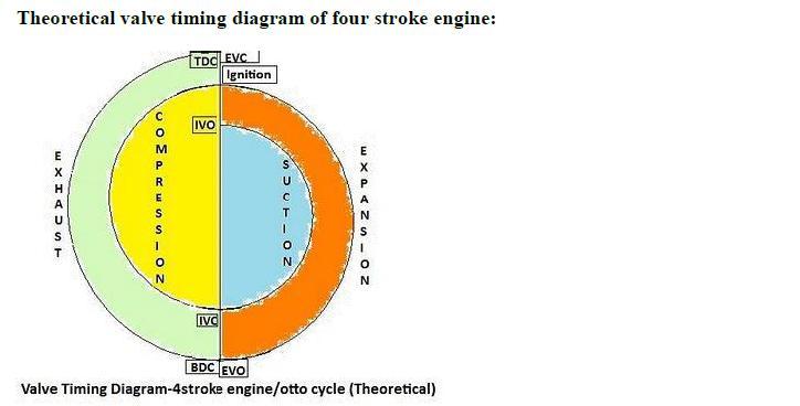
21 Actual PV diagram of four stroke engine Theoretical PV diagram for four stroke engine 21
22 Theoretical and Actual PV diagram of Two stroke Petrol Engine: 22
23 Problems: Problems to determine, 1. Air Standard Efficiency 2. Mean Effective Pressure for Air Standard Cycles Sample Problems 1. A Dual combustion air standard cycle has a compression ratio of 10. The constant pressure part of combustion takes place at 40 bar. The highest and the lowest temperature of the cycle are 1727 C and 27 C respectivety. The pressure at the beginning of compression is 1 bar. Calculate- (i) The pressure and temperature at key points of the cycle. (ii) The heat supplied at constant volume, (iii) The heat supplied at constant pressure (iv) The heat rejected (v) The Work output, (vi) The efficiency and (vii) Mean effective pressure. 23
24 2. An Engine working on Otto cycle has a volume of 0.45 m3, pressure 1 bar and temperature 30Oc, at the beginning of compression stroke. At the end of Compression stroke, the pressure is 11 bar and 210 KJ of heat is added at constant Volume. Determine i. Pressure, temperature and volumes at salient points in the cycle. ii. Efficiency. 24
25 UNIT-II INTERNAL COMBUSTION ENGINES Classification of IC engine: Normally IC engines are classified into 1.C.I engines and 2.S.I engines Some of the important classifications are given below, 1. Number of strokes -two stroke and four stroke 2. Working Cycles -Otto,Diesel, Dual cycle 3. Cylinder arrangement -In-line, V-type, Opposed, Radial 4. Valve Arrangement -T-head, F-head, L-head, I-head 5. Fuel Used -Petrol, Diesel, Gas 6. Combustion chamber design -Open, divided 7. Cooling System - Water and air cooling 8. According to the number of cylinders -Single and Multi 9. According to the speed -Slow, medium, and high speed engines 10. According to the application -Stationary, Automotive, Marine, Locomotive, Aircraft etc., Components of I.C engine 1.Cylinder block: The cylinder block is the main body of the engine, the structure that supports all the other components of the engine. In the case of the single cylinder engine the cylinder block houses the cylinder, while in the case of multi-cylinder engine the number of cylinders are cast together to form the cylinder block. The cylinder head is mounted at the top of the cylinder block. When the vehicle runs, large amounts of heat are generated within the cylinder block. To remove this heat the cylinder block and the cylinder head are cooled by water flowing through the water jackets within larger engines such as those found in cars and trucks. For smaller vehicles like motorcycles, fins are provided on the cylinder block and on the cylinder head to cool them. The bottom portion of the cylinder block is called a crankcase. Within the crankcase is where lubricating oil, which is used for lubricating various moving parts of the engine, is stored. 2) Cylinder: As the name suggests it is a cylindrical shaped vessel fitted in the cylinder block. This cylinder can be removed from the cylinder block and machined whenever required to. It is also called a liner or sleeve. Inside the cylinder the piston moves up and down, which is called the reciprocating motion of the piston. Burning of fuel occurs at the top of the cylinder, due to which the reciprocating motion of the piston is produced. The surface of the cylinder is finished to a high finish, so that there is minimal friction between the piston and the cylinder. 3) Piston: The piston is the round cylindrical component that performs a reciprocating motion inside the cylinder. While the cylinder itself is the female part, the piston is the male part. The piston fits perfectly inside the cylinder. Piston rings are fitted over the piston. The gap between the piston and the cylinder is filled by the piston rings and lubricating oil. The piston is usually made up of 25
26 aluminum. 4) Piston rings: The piston rings are thin rings fitted in the slots made along the surface of the piston. It provides a tight seal between the piston and the cylinder walls that prevents leaking of the combustion gases from one side to the other. This ensures that that motion of the piston produces as close as to the power generated from inside the cylinder. 5) Combustion chamber: It is in the combustion chamber where the actual burning of fuel occurs. It is the uppermost portion of the cylinder enclosed by the cylinder head and the piston. When the fuel is burnt, much thermal energy is produced which generates excessively high pressures causing the reciprocating motion of the piston. 6) Inlet manifold: Through the inlet manifold the air or air-fuel mixture is drawn into the cylinder. 7) Exhaust manifold: All the exhaust gases generated inside the cylinder after burning of fuel are discharged through the exhaust manifold into the atmosphere. 8) Inlet and exhaust valves: The inlet and the exhaust valves are placed at the top of the cylinder in the cylinder head. The inlet valve allows the intake of the fuel during suction stroke of the piston and to close thereafter. During the exhaust stroke of the piston the exhaust valves open allowing the exhaust gases to release to the atmosphere. Both these valves allow the flow of fuel and gases in single direction only. 9) Spark plug: The spark plug is a device that produces a small spark that causes the instant burning of the pressurized fuel. 10) Connecting rod: It is the connecting link between the piston and the crankshaft that performs the rotary motion. There are two ends of the connecting rod called the small end and big end. The small end of the connecting rod is connected to the piston by gudgeon pin, while the big end is connected to crankshaft by crank pin. 11) Crankshaft: The crankshaft performs the rotary motion. It is connected to the axle of the wheels which move as the crankshaft rotates. The reciprocating motion of the piston is converted into the rotary motion of the crankshaft with the help of connecting rod. The crankshaft is located in the crankcase and it rotates in the bushings. 12) Camshaft: It takes driving force from crankshaft through gear train or chain and operates the inlet valve as well as exhaust valve with the help of cam followers, push rod and rocker arms. 26
27 27

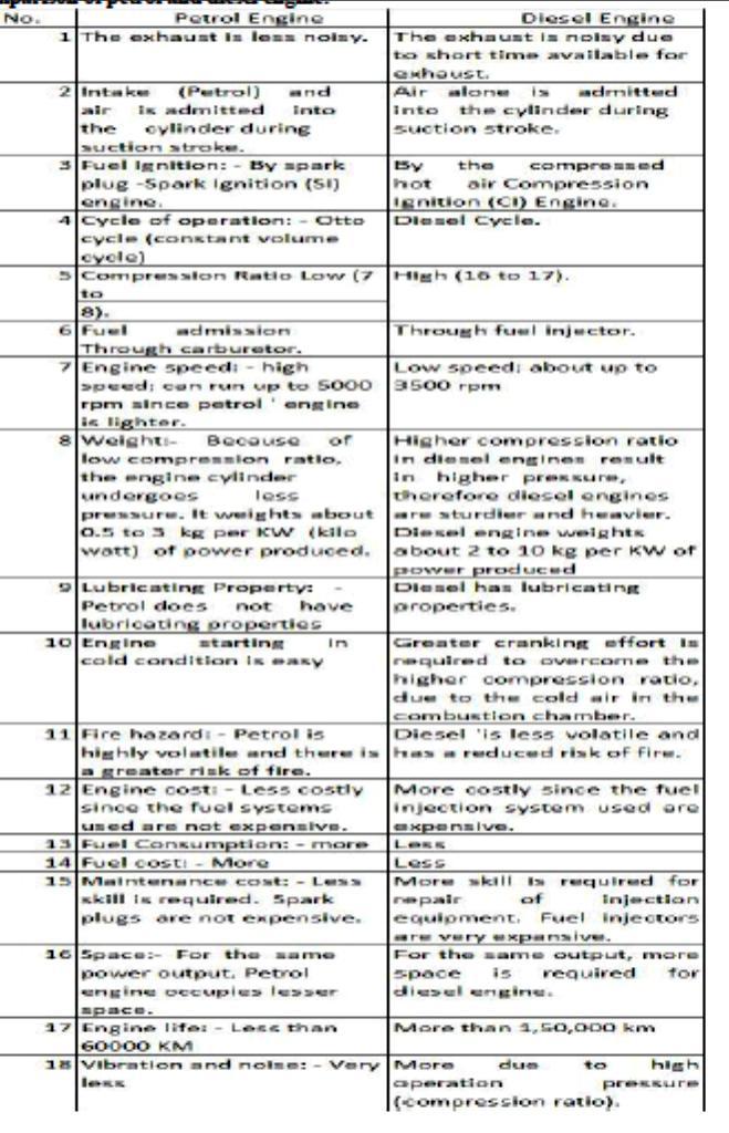
28 1- IPO 2- IPC 3- EPO 4- TPO 5- TPC 6-EPC Comparison of two stroke and four stroke engines: Comparison of petrol and diesel engine: 28
29 29

30 Simple Carburetor: The function of a carburetor is to vaporize the petrol (gasoline) by means of engine suction and to supply the required air and fuel (petrol) mixture to the engine cylinder. During the suction stroke, air flows from atmosphere into the cylinder. As the air passes through the enture, velocity of air increases and its pressure falls below the atmosphere. The pressure at the nozzle tip is also below the atmospheric pressure. The pressure on the fuel surface of the fuel tank is atmospheric. Due to which a pressure difference is created, which causes the flow of fuel through the fuel jet into the air stream. As the fuel and air pass ahead of the enture, the fuel gets vaporized and required uniform mixture is supplied to the engine. The quantity of fuel supplied to the engine depends upon the opening of throttle valve which is governed by the governor. The main parts of a simple carburetor are: Float chamber: The level of fuel in the float chamber is maintained slightly below the tip of the nozzle. If the level of petrol is above then the petrol will run from the nozzle and drip from the carburetor. If the petrol level is kept low than the tip of the nozzle then part of pressure head is lost in lifting the petrol up to the tip of nozzle. Generally it is kept at 5mm from the level of petrol in the float chamber. The level of the fuel is kept constant with the help of float and needle valve. The needle valve closes the inlet supply from main tank if the level rises above the required level. If the level of fuel decreases then the needle valve opens the supply. Generally the fuel level is kept 5mm below the nozzle tip. Venturi: When the mixture passes through the 30

31 narrowest section its velocity increases and pressure falls below the atmospheric. As it passes through the divergent section, pressure increases again. Throttle valve: It controls the quantity of air and fuel mixture supplied to the engine through intake manifold and also the head under which the fuel flows. Choke: It provides an extra rich mixture during to the engine starting and in cold weather to warm up the engine. The choke valve is nearly closed during clod starting and warming. It creates a high vacuum near the fuel jet which causes flow of more fuel from the jet. Diesel Pump and Injector system: 31


32 Diesel knocking and detonation: We already know that if the delay period is long, a large amount of fuel will be injected and accumulated in the chamber. The auto ignition of this large 32
33 amount of fuel may cause high rate of pressure rise and high maximum pressure which may cause knocking in diesel engines. A long delay period not only increases the amount of fuel injected by the moment of ignition, but also improve the homogeneity of the fuel air mixture and its chemical preparedness for explosion type self ignition similar to detonation in SI engines. It is very instructive to compare the phenomenon of detonation is SI ensues with that of knocking in CI engines. There is no doubt that these two phenomena are fundamentally similar. Both are processes of auto ignition subject to the ignition time lag characteristic of the fuel air mixture. However, differences in the knocking phenomena of the SI engine and the CI engine should also be care fully be noted: 1. In the SI engine, the detonation occurs near the end of combustion where as in the CI engine detonation occurs near the beginning of combustion as shown in fig The detonation in the SI engine is of a homogeneous charge causing very high rate of pressure rise and very high maximum pressure. In the CI engine the fuel and air are in perfectly mixed and hence the rate of pressure rise is normally lower than that in the detonating part of the charge in the SI engine. 3. Since in the CI engine the fuel is injected in to the cylinder only at the end of the compression stroke there is no question of pre ignition or pre mature ignition as in the SI engine. 4. In the SI engine it is relatively easy to distinguish between knocking and non- knocking operation as the human ear easily find the distinction. However, in the case of the CI engine the normal ignition is itself by auto ignition and hence no CI engines have a sufficiently high rate of pressure rise per degree crank angle to cause audible noise. When such noise becomes excessive or there is excessive vibration in engine structure, in the opinion of the observer, the engine is sending to knock. It is clear that personal judgment is involved here. Thus in the CI engine there is no definite distinction between normal and knocking combustion. The maximum rate of pressure rise in the CI engine may reach as high as 10bar per crank degree angle. It is most important to note that factors that tend to reduce detonation in the SI engine increase knocking in CI engine and vice versa because of the following reason. The detonation of knocking in the SI engine is due to simultaneous auto ignition of the last part of the charge. To eliminate detonation in the SI engine we want to prevent all together the auto ignition of the last part of the charge and therefore desire a long delay period and high self ignition temperature of the fuel. To eliminate knocking the CI engine we want to achieve auto ignitions early as possible therefore desire a short delay period and low self ignition temperature of the fuel. Table 6.2 gives the factors which reduce knocking in the SI and CI engines. Table: Factors tending to reduce knocking in SI and CI engine 33
34 It is also clear from the table and discussion that a good CI engine fuel is a bad SI engine fuel and a good SI engine is bad CI engine fuel. In other words diesel oil has low self ignition temperature and short time lag where as petrol have high self ignition temperature and a long ignition lag. In terms of fuel rating diesel oil has high cetane number (40 60) and low octane number (about 30) and petrol has high octane number (80 90) and low cetane number (18). Ignition System: Basically Convectional Ignition systems are of 2 types : (a) Battery or Coil Ignition System, and (b) Magneto Ignition System. Both these conventional, ignition systems work on mutual electromagnetic induction principle. Battery ignition system was generally used in 4-wheelers, but now-a-days it is more commonly used in 2-wheelers also (i.e. Button start, 2- wheelers like Pulsar, Kinetic Honda; Honda-Activa, Scooty, Fiero, etc.). In this case 6 V or 12 V batteries will supply necessary current in the primary winding. Magneto ignition system is mainly used in 2-wheelers, kick start engines. (Example, Bajaj Scooters, Boxer, Victor, Splendor, Passion, etc.). In this case magneto will produce and supply current to the primary winding. So in magneto ignition system magneto replaces the battery. Battery or Coil Ignition System Figure shows line diagram of battery ignition system for a 4-cylinder petrol engine. It mainly consists of a 6 or 12 volt battery, ammeter, ignition switch, auto-transformer (step up transformer), contact breaker, capacitor, distributor rotor, distributor contact points, spark plugs, etc. Note that the Figure 4.1 shows the ignition system for 4-cylinder petrol engine, here there are 4- spark plugs and contact breaker cam has 4-corners. (If it is for 6-cylinder engine it will have 6- spark plugs and contact breaker cam will be a hexagon). The ignition system is divided into 2-circuits : 34
35 i. Primary Circuit : It consists of 6 or 12 V battery, ammeter, ignition switch, primary winding it has turns of 20 SWG (Sharps Wire Gauge) gauge wire, contact breaker, capacitor. (ii) Secondary Circuit : It consists of secondary winding. Secondary Ignition Systems winding consists of about turns of 40 (S WG) gauge wire. Bottom end of which is connected to bottom end of primary and top end of secondary winding is connected to centre of distributor rotor. Distributor rotors rotate and make contacts with contact points and are connected to spark plugs which are fitted in cylinder heads (engine earth). (iii) Working : When the ignition switch is closed and engine in cranked, as soon as the contact breaker closes, a low voltage current will flow through the primary winding. It is also to be noted that the contact beaker cam opens and closes the circuit 4-times (for 4 cylinders) in one revolution. When the contact breaker opens the contact, the magnetic field begins to collapse. Because of this collapsing magnetic field, current will be induced in the secondary winding. And because of more turns (@ turns) of secondary, voltage goes unto volts. This high voltage current is brought to centre of the distributor rotor. Distributor rotor rotates and supplies this high voltage current to proper stark plug depending upon the engine firing order. When the high voltage current jumps the spark plug gap, it produces the spark and the charge is ignited-combustion starts-products of combustion expand and produce power. Magneto Ignition System 35
36 In this case magneto will produce and supply the required current to the primary winding. In this case as shown, we can have rotating magneto with fixed coil or rotating coil with fixed magneto for producing and supplying current to primary, remaining arrangement is same as that of a battery ignition system. Comparison between Battery and Magneto Ignition System: 36
37 Lubrication System: The splash system is no longer used in automotive engines. It is widely used in small four-cycle engines for lawn mowers, outboard marine operation, and so on. In the splash lubricating system, oil is splashed up from the oil pan or oil trays in the lower part of the crankcase. The oil is thrown upward as droplets or fine mist and provides adequate lubrication to valve mechanisms, piston pins, cylinder walls, and piston rings. In the engine, dippers on the connecting-rod bearing caps enter the oil pan with each crankshaft revolution to produce the oil splash. A passage is drilled in each connecting rod from the dipper to the bearing to ensure lubrication. This system is too uncertain for automotive applications. One reason is that the level of oil in the crankcase will vary greatly the amount of lubrication received by the engine. A high level results in excess lubrication and oil consumption and a slightly low level results in inadequate lubrication and failure of the engine. Combination Splash and Force Feed : 37

38 In a combination splash and force feed, oil is delivered to some parts by means of splashing and other parts through oil passages under pressure from the oil pump. The oil from the pump enters the oil galleries. From the oil galleries, it flows to the main bearings and camshaft bearings. The main bearings have oil-feed holes or grooves that feed oil into drilled passages in the crankshaft. The oil flows through these passages to the connecting rod bearings. From there, on some engines, it flows through holes drilled in the connecting rods to the piston-pin bearings. Cylinder walls are lubricated by splashing oil thrown off from the connecting-rod bearings. Some engines use small troughs under each connecting rod that are kept full by small nozzles which deliver oil under pressure from the oil pump. These oil nozzles deliver an increasingly heavy stream as speed increases. At very high speeds these oil streams are powerful enough to strike the dippers directly. This causes a much heavier splash so that adequate lubrication of the pistons and the connecting-rod bearings is provided at higher speeds. If a combination system is used on an overhead valve engine, the upper valve train is lubricated by pressure from the pump. Force Feed : 38

39 A somewhat more complete pressurization of lubrication is achieved in the force-feed lubrication system. Oil is forced by the oil pump from the crankcase to the main bearings and the camshaft bearings. Unlike the combination system the connecting-rod bearings are also fed oil under pressure from the pump. Oil passages are drilled in the crankshaft to lead oil to the connecting-rodbearings. The passages deliver oil from the main bearing journals to the rod bearing journals. In some engines, theseopening are holes that line up once for every crankshaft revolution. In other engines, there are annular grooves in the main bearings through which oil can feed constantly into the hole in the crankshaft. The pressurized oil that lubricates the connecting-rod bearings goes on to lubricate the pistons and walls by squirting out through strategically drilled holes. This lubrication system is used in virtually all engines that are equipped with semifloating piston pins. Full Force Feed: In a full force-feed lubrication system, the main bearings, rod bearings, camshaft bearings, and the complete valve mechanism are lubricated by oil under pressure. In addition, the full forcefeed lubrication system provides lubrication under pressure to the pistons and the piston pins. This is accomplished by holes drilled the length of the connecting rod, creating an oil passage from the connecting rod bearing to the piston pin bearing. This passage not only feeds the piston pin bearings but also provides lubrication for the pistons and cylinder walls. This system is used in virtually all engines that are equipped with full-floating piston pins. Cooling System: Air Cooled System 39
40 Air cooled system is generally used in small engines say up to Kw and in aero plane engines. In this system fins or extended surfaces are provided on the cylinder walls, cylinder head, etc. Heat generated due to combustion in the engine cylinder will be conducted to the fins and when the air flows over the fins, heat will be dissipated to air. The amount of heat dissipated to air depends upon : (a) Amount of air flowing through the fins. (b) Fin surface area. I Thermal conductivity of metal used for fins. Advantages of Air Cooled System Following are the advantages of air cooled system : (a) Radiator/pump is absent hence the system is light. (b) In case of water cooling system there are leakages, but in this case there are no leakages. I Coolant and antifreeze solutions are not required. (d) This system can be used in cold climates, where if water is used it may freeze. Disadvantages of Air Cooled System (a) Comparatively it is less efficient. (b) It is used only in aero planes and motorcycle engines where the engines are exposed to air directly. Water Cooling System: In this method, cooling water jackets are provided around the cylinder, cylinder head, valve seats etc. The water when circulated through the jackets, it absorbs heat of combustion. This hot water will then be cooling in the radiator partially by a fan and partially by the flow developed by the forward motion of the vehicle. The cooled water is again recirculated through the water jackets. 40
41 Types of Water Cooling System There are two types of water cooling system : Thermo Siphon System In this system the circulation of water is due to difference in temperature (i.e. difference in densities) of water. So in this system pump is not required but water is circulated because of density difference only. Pump Circulation System In this system circulation of water is obtained by a pump. This pump is driven by means of engine output shaft through V-belts. Performance Calculation: Engine performance is an indication of the degree of success of the engine performs its assigned task, i.e. the conversion of the chemical energy contained in the fuel into the useful mechanical work. The performance of an engine is evaluated on the basis of the following : (a) Specific Fuel Consumption. (b) Brake Mean Effective Pressure. I Specific Power Output. (d) Specific Weight. (e) Exhaust Smoke and Other Emissions. The particular application of the engine decides the relative importance of these performance parameters. 41
42 For Example : For an aircraft engine specific weight is more important whereas for an industrial engine specific fuel consumption is more important. For the evaluation of an engine performance few more parameters are chosen and the effect of various operating conditions, design concepts and modifications on these parameters are studied. The basic performance parameters are the following : (a) Power and Mechanical Efficiency. (b) Mean Effective Pressure and Torque. I Specific Output. (d) Volumetric Efficiency. (e) Fuel-air Ratio. (f) Specific Fuel Consumption. (g) Thermal Efficiency and Heat Balance. (h) Exhaust Smoke and Other Emissions. (i) Specific Weight. Power and Mechanical Efficiency The main purpose of running an engine is to obtain mechanical power. Power is defined as the rate of doing work and is equal to the product of force and linear velocity or the product of torque and angular velocity. Thus, the measurement of power involves the measurement of force (or torque) as well as speed. The force or torque is measured with the help of a dynamometer and the speed by a tachometer. The power developed by an engine and measured at the output shaft is called the brake power (bp) and is given by bp=2πnt/60 where, T is torque in N-m and N is the rotational speed in revolutions per minute. The total power developed by combustion of fuel in the combustion chamber is, however, more than the bp and is called indicated power (ip). Of the power developed by the engine, i.e. ip, some power is consumed in overcoming the friction between moving parts, some in the process of inducting the air and removing the products of combustion from the engine combustion chamber. Indicated Power It is the power developed in the cylinder and thus, forms the basis of evaluation of combustion efficiency or the heat release in the cylinder. Where, I.P= PmLANK/60 pm = Mean effective pressure, N/m2, L = Length of the stroke, m, A = Area of the piston, m2, N = Rotational speed of the engine, rpm (It is N/2 for four stroke engine), and k = Number of cylinders. Thus, we see that for a given engine the power output can be measured in terms of mean effective pressure. The difference between the ip and bp is the indication of the power lost in the mechanical components of the engine (due to friction) and forms the basis of mechanical efficiency; which is defined as follows : Mechanical efficiency=bp/ip 42
43 The difference between ip and bp is called friction power (fp). Fp = ip bp Mechanical efficiency= b.p/(bp+fp) Mean Effective Pressure and Torque Mean effective pressure is defined as a hypothetical/average pressure which is assumed to be acting on the piston throughout the power stroke. Therefore, Pm=60Xi.P/LANk where, Pm = Mean effective pressure, N/m2, Ip = Indicated power, Watt, L = Length of the stroke, m, A = Area of the piston, m2, N = Rotational speed of the engine, rpm (It is N/2 for four stroke engine), and k = Number of cylinders. If the mean effective pressure is based on bp it is called the brake mean effective pressure( Pm), and if based on ihp it is called indicated mean effective pressure (imep). Similarly, the friction mean effective pressure (fmep) can be defined as, fmep = imep bmep The torque is related to mean effective pressure by the relation B.P=2Πnt/60 I.P=PmLANk/60 2Πnt/60=[bmep.A.L.(Nk/60)] or, T=(bmep.A.L.k)/2π Thus, the torque and the mean effective pressure are related by the engine size. A large engine produces more torque for the same mean effective pressure. For this reason, torque is not the measure of the ability of an engine to utilize its displacement for producing power from fuel. It is the mean effective pressure which gives an indication of engine displacement utilization for this conversion. Higher the mean effective pressure, higher will be the power developed by the engine for a given displacement. Again we see that the power of an engine is dependent on its size and speed. Therefore, it is not possible to compare engines on the basis of either power or torque. Mean effective pressure is the true indication of the relative performance of different engines. Specific Output Specific output of an engine is defined as the brake power (output) per unit of piston displacement and is given by, 43
44 Specific output=b.p/a.l Constant = bmep rpm The specific output consists of two elements the bmep (force) available to work and the speed with which it is working. Therefore, for the same piston displacement and bmep an engine operating at higher speed will give more output. It is clear that the output of an engine can be increased by increasing either speed or bmep. Increasing speed involves increase in the mechanical stress of various engine parts whereas increasing bmep requires better heat release and more load on engine cylinder. Volumetric Efficiency Volumetric efficiency of an engine is an indication of the measure of the degree to which the engine fills its swept volume. It is defined as the ratio of the mass of air inducted into the engine cylinder during the suction stroke to the mass of the air corresponding to the swept volume of the engine at atmospheric pressure and temperature. Alternatively, it can be defined as the ratio of the actual volume inhaled during suction stroke measured at intake conditions to the swept volume of the piston. The amount of air taken inside the cylinder is dependent on the volumetric efficiency of an engine and hence puts a limit on the amount of fuel which can be efficiently burned and the power output. For supercharged engine the volumetric efficiency has no meaning as it comes out to be more than unity. Fuel-Air Ratio (F/A) Fuel-air ratio (F/A) is the ratio of the mass of fuel to the mass of air in the fuel-air mixture. Air-fuel ratio (A/F) is reciprocal of fuel-air ratio. Fuel-air ratio of the mixture affects the combustion phenomenon in that it determines the flame propagation velocity, the heat release in the combustion chamber, the maximum temperature and the completeness of combustion. Relative fuel-air ratio is defined as the ratio of the actual fuel-air ratio to that of the stoichiometric fuel-air ratio required to burn the fuel supplied. Stoichiometric fuel-air ratio is the ratio of fuel to air is one in which case fuel is completely burned due to minimum quantity of air supplied. Relative fuel-air ratio, =(Actual Fuel- Air ratio)/(stoichiometric fuel-air ratio) Brake Specific Fuel Consumption Specific fuel consumption is defined as the amount of fuel consumed for each unit of brake power developed per hour. It is a clear indication of the efficiency with which the engine develops power from fuel. B.S.F.C= Relative fuel-air ratio, =(Actual Fuel- Air ratio)/(stoichiometric fuel-air ratio) This parameter is widely used to compare the performance of different engines. 44
45 Thermal Efficiency and Heat Balance Thermal efficiency of an engine is defined as the ratio of the output to that of the chemical energy input in the form of fuel supply. It may be based on brake or indicated output. It is the true indication of the efficiency with which the chemical energy of fuel (input) is converted into mechanical work. Thermal efficiency also accounts for combustion efficiency, i.e., for the fact that whole of the chemical energy of the fuel is not converted into heat energy during combustion. Brake thermal efficiency = B.P/mf* Cv where, Cv = Calorific value of fuel, Kj/kg, and mf = Mass of fuel supplied, kg/sec. The energy input to the engine goes out in various forms a part is in the form of brake output, a part into exhaust, and the rest is taken by cooling water and the lubricating oil. The break-up of the total energy input into these different parts is called the heat balance. The main components in a heat balance are brake output, coolant losses, heat going to exhaust, radiation and other losses. Preparation of heat balance sheet gives us an idea about the amount of energy wasted in various parts and allows us to think of methods to reduce the losses so incurred. Exhaust Smoke and Other Emissions: Smoke and other exhaust emissions such as oxides of nitrogen, unburned hydrocarbons, etc. are nuisance for the public environment. With increasing emphasis on air pollution control all efforts are being made to keep them as minimum as it could be. Smoke is an indication of incomplete combustion. It limits the output of an engine if air pollution control is the consideration. Emission Formation Mechanisms: (S.I) This section discusses the formation of HC, CO, Nox, CO2, and aldehydes and explains the effects of design parameters. i. Hydrocarbon Emissions HC emissions are various compounds of hydrogen, carbon, and sometimes oxygen. They are burned or partially burned fuel and/or oil. HC emissions contribute to photochemical smog, ozone, and eye irritation. There are several formation mechanisms for HC, and it is convenient to think about ways HC can avoid combustion and ways HC can be removed; we will discuss each below. Of course, most of the HC input is fuel, and most of it is burned during normal combustion. However, some HC avoids oxidation during this process. The processes by which fuel compounds escape burning during normal S.I. combustion are: 1. Fuel vapor-air mixture is compressed into the combustion chamber crevice volumes. 2. Fuel compounds are absorbed into oil layers on the cylinder liner. 3. Fuel is absorbed by and/or contained within deposits on the piston head and piston crown. 4. Quench layers on the 45
46 combustion chamber wall are left as the flame extinguishes close to the walls. 5. Fuel vapor-air mixture can be left unburned if the flame extinguishes before reaching the walls. 6. Liquid fuel within the cylinder may not evaporate and mix with sufficient air to burn prior to the end of combustion. 7. The mixture may leak through the exhaust valve seat. (ii) Carbon Monoxide Formation of CO is well established. Under some conditions, there is not enough O2 available for complete oxidation and some of the carbon in the fuel ends up as CO. The amount of CO, for a range of fuel composition and C/H ratios, is a function of the relative air-fuel ratio. Even when enough oxygen is present, high peak temperatures can cause dissociation chemical combustion reactions in which carbon dioxide and water vapor separate into CO, H2, and O2. Conversion of CO to CO2 is governed by reaction CO + OH CO2 + H Dissociated CO may freeze during the expansion stroke. (iii) Oxides of Nitrogen Nox is a generic term for the compounds NO and NO2. Both are present to some degree in the exhaust, and NO oxidizes to NO2 in the atmosphere. Nox contributes to acid rain and photochemical smog; it is also thought to cause respiratory health problems at atmospheric concentrations found in some parts of the world. To understand Nox formation, we must recognize several factors that affect Nox equilibrium. Remember that all chemical reactions proceed toward equilibrium at some reaction rate. Equilibrium NO (which comprises most of the Nox formation) is formed at a rate that varies strongly with temperature and equivalence ratio. (iv) Carbon Dioxide While not normally considered a pollutant, CO2 may contribute to the greenhouse effect. Proposals to reduce CO2 emissions have been made. CO2 controls strongly influence fuel economy requirements. (v) Aldehydes Aldehydes are the result of partial oxidation of alcohols. They are not usually present in significant quantities in gasoline-fueled engines, but they are an issue when alcohol fuels are used. Aldehydes are thought to cause lung problems. So far, little information of engine calibration effects on aldehyde formation is available. Emission Formation In C.I. Engine For many years, diesel engines have had a reputation of giving poor performance and producing black smoke, an unpleasant odor, and considerable noise. However, it would find it difficult to distinguish today s modern diesel car from its gasoline counterpart. For diesel engines the emphasis is to reduce emissions of Nox and particulates, where these emissions are typically higher than those from equivalent port injected gasoline engines equipped with three-way catalysts. Catalyst of diesel exhaust remains a problem insofar as researchhas not yet been able to come up with an effective converter that eliminates both particulate matter (PM) and oxide of nitrogen (Nox). 46
47 Principle C.I. Engine Exhaust Constituents For many years, diesel engines have had a reputation of giving poor performance and producing black smoke, an unpleasant odor, and considerable noise. However, it would find it difficult to distinguish today s modern diesel car from its gasoline counterpart. Concerning CO and HC emissions, diesel engines have an inherent advantages, therefore the emphasis is to reduce emissions of Nox and particulates, where these emissions are typically higher than those from equivalent port injected gasoline engines equipped with three-way catalysts. Catalyst of diesel exhaust remains a problem insofar as research has not yet been able to come up with an effective converter that eliminates both particulate matter (PM) and oxide of nitrogen (Nox). In the same manner as with SI engines, the air/fuel ratio of the diesel engine has a significant impact on the level of pollutant concentrations but this parameter is not freely available for minimizing pollution. Problems: To determine Brake power, Indicated Power, Frictional Power, Brake Thermal Efficiency, Indicated Thermal Efficiency, Mechanical Efficiency, Relative Efficiency, Volumetric Efficiency, Brake Specific Fuel Consumption, Indicated Specific Fuel Consumption, Indicated mean effective pressure, Brake mean effective pressure. Problems: To determine Brake power, Indicated Power, Frictional Power, Brake Thermal Efficiency, Indicated Thermal Efficiency, Mechanical Efficiency, Relative Efficiency, Volumetric Efficiency, Brake Specific Fuel Consumption, Indicated Specific Fuel Consumption, Indicated mean effective pressure, Brake mean effective pressure. 2.A six cylinder, 4 stroke SI engine having a piston displacement of 700cm3 per cylinder developed 78Kw at 3200 rpm and consumed 27 kg of petrol per hour. The calorific value of the fuel is 44MJ/kg. Estimate 1.The volumetric efficiency of the engine if the air-fuel ratio is 12 and intake air is at 0.9bar,32oC. 2.Brake thermal efficiency and brake torque. For air R=0.287 Kj/kgK. 47
48 UNIT-III STEAM NOZZLES AND TURBINES Flow of steam through nozzles : - The flow of steam through nozzles may be regarded as adiabatic expansion. - The steam has a very high velocity at the end of the expansion, and the enthalpy decreases as expansion takes place. - Friction exists between the steam and the sides of the nozzle; heat is produced as the result of the resistance to the flow. - The phenomenon of supersaturation occurs in the flow of steam through nozzles. This is due to the time lag in the condensation of the steam during the expansion. Continuity and steady flow energy equations Through a certain section of the nozzle: m.v = A.C m is the mass flow rate, v is the specific volume, A is the cross-sectional area and C is the velocity. Types of Nozzles: 1. Convergent Nozzle 2. Divergent Nozzle 3. Convergent-Divergent Nozzle 48
49 Supersaturated flow or Metastable flow in Nozzles : As steam expands in the nozzle, its pressure and temperature drop, and it is expected that the steam start condensing when it strikes the saturation line. But this is not always the case. Owing to the high velocities, the residence time of the steam in the nozzle is small, and there may not sufficient time for the necessary heat transfer and the formation of liquid droplets. Consequently, the condensation of steam is delayed for a little while. This phenomenon is known as supersaturation, and the steam that exists in the wet region without containing any liquid is known as supersaturated steam. The locus of points where condensation will take place regardless of the initial temperature and pressure at the nozzle entrance is called the Wilson line. The Wilson line lies between 4 and 5 49

50 percent moisture curves in the saturation region on the h-s diagram for steam, and is often approximated by the 4 percent moisture line. The supersaturation phenomenon is shown on the h- s chart below: Effects of Supersaturation: Critical Pressure Ratio: The critical pressure ratio is the pressure ratio which will accelerate the flow to a velocity equal to the local velocity of sound in the fluid. Critical flow nozzles are also called sonic chokes. By establishing a shock wave the sonic choke establish a fixed flow rate unaffected by the differential pressure, any fluctuations or changes in downstream pressure. A sonic choke may provide a simple way to regulate a gas flow. 50
51 The ratio between the critical pressure and the initial pressure for a nozzle can expressed as Effect of Friction on Nozzles: 1) Entropy is increased. 2) Available energy is decreased. 3) Velocity of flow at throat is decreased. 4) Volume of flowing steam is decreased. 5) Throat area necessary to discharge a given mass of steam is increased. 51

52 Velocity of steam at nozzle exit: Mass of steam discharged through a nozzle: Condition for maximum discharge through nozzle: The nozzle is always designed for maximum discharge 52
53 Values for maximum discharge: 53
54 Where P1 is the initial pressure of the steam in kpa and v1 is the specific volume of the steam in m3/kg at the initial pressure STEAM TURBINES: Normally the turbines are classified into types, 1. Impulse Turbine 2. Reaction Turbine Impulse and Reaction Turbines: 54

55 Impulse Turbines The steam jets are directed at the turbine s bucket shaped rotor blades where the pressure exerted by the jets causes the rotor to rotate and the velocity of the steam to reduce as it imparts its kinetic energy to the blades. The blades in turn change change the direction of flow of the steam however its pressure remains constant as it passes through the rotor blades since the cross section of the chamber between the blades is constant. Impulse turbines are therefore also known as constant pressure turbines. The next series of fixed blades reverses the direction of the steam before it passes to the second row of moving blades. Reaction Turbines The rotor blades of the reaction turbine are shaped more like aerofoils, arranged such that the cross section of the chambers formed between the fixed blades diminishes from the inlet side towards the exhaust side of the blades. The chambers between the rotor blades essentially form nozzles so that as the steam progresses through the chambers its velocity increases while at thesame time its pressure decreases, just as in the nozzles formed by the fixed blades. Thus the pressure decreases in both the fixed and moving blades. As the steam emerges in a jet from between the rotor blades, it creates a reactive force on the blades which in turn creates the turning moment on the turbine rotor, just as in Hero s steam engine. (Newton s Third Law For every action there is an equal and opposite reaction) 55
56 Compounding of impulse turbine : - This is done to reduce the rotational speed of the impulse turbine to practical limits. (A rotor speed of 30,000 rpm is possible, which is pretty high for practical uses.) - Compounding is achieved by using more than one set of nozzles, blades, rotors, in a series, keyed to a common shaft; so that either the steam pressure or the jet velocity is absorbed by the turbine in stages. - Three main types of compounded impulse turbines are: a) Pressure compounded, b) velocity compounded and c) pressure and velocity compounded impulse turbines. 1.Velocity Compounding: Pi = Inlet Pressure Pe= Exit Pressure Vi=Inlet Velocity Ve=Exit Velocity The velocity-compounded impulse turbine was first proposed by C.G. Curtis to solve the problems of a single-stage impulse turbine for use with high pressure and temperature steam. The Curtis stage turbine, as it came to be called, is composed of one stage of nozzles as the singlestage turbine, followed by two rows of moving blades instead of one. These two rows are separated by one row of fixed blades attached to the turbine stator, which has the function of 56
57 redirecting the steam leaving the first row of moving blades to the second row of moving blades. A Curtis stage impulse turbine is shown in Fig. with schematic pressure and absolute steamvelocity changes through the stage. In the Curtis stage, the total enthalpy drop and hence pressure drop occur in the nozzles so that the pressure remains constant in all three rows of blades. 2.Pressure Compounding: This involves splitting up of the whole pressure drop from the steam chest pressure to the condenser pressure into a series of smaller pressure drops across several stages of impulse turbine. -The nozzles are fitted into a diaphragm locked in the casing. This diaphragm separates one wheel chamber from another. All rotors are mounted on the same shaft and the blades are attached on the rotor. 3.Pressure-Velocity Compounding This is a combination of pressure and velocity compounding. 57

58 A two-row velocity compounded turbine is found to be more efficient than the three-row type. In a two-step pressure velocity compounded turbine, the first pressure drop occurs in the first set of nozzles, the resulting gain in the kinetic energy is absorbed successively in two rows of moving blades before the second pressure drop occurs in the second set of nozzles. Since the kinetic energy gained in each step is absorbed completely before the next pressure drop, the turbine is pressure compounded and as well as velocity compounded. The kinetic energy gained due to the second pressure drop in the second set of nozzles is absorbed successively in the two rows of moving blades. The pressure velocity compounded steam turbine is comparatively simple in construction and is much more compact than the pressure compounded turbine. 58

59 Velocity diagram of an impulse turbine: 59
60 60
61 61
62 The fixed blades are used to guide the outlet steam/gas from the previous stage in such a manner so as to smooth entry at the next stage is ensured. K, the blade velocity coefficient may be different in each row of blades 62
63 Velocity diagram of the velocity compounded turbines: Reaction Turbine: A reaction turbine, therefore, is one that is constructed of rows of fixed and rows of moving blades. The fixed blades act as nozzles. The moving blades move as a result of the impulse of steam received (caused by change in momentum) and also as a result of expansion and acceleration of the steam relative to them. In other words, they also act as nozzles. The enthalpy drop per stage of one row fixed and one row moving blades is divided among them, often equally. Thus a blade with a 50 percent degree of reaction, or a 50 percent reaction stage, is one in which half the enthalpy drop of the stage occurs in the fixed blades and half in the moving blades. The pressure drops will not be equal, however. They are greater for the fixed blades and greater for the high-pressure than the low-pressure stages. The moving blades of a reaction turbine are easily distinguishable from those of an impulse turbine in that they are not symmetrical and, because they act partly as nozzles, have a shape similar to that of the fixed blades, although curved in the 63
64 opposite direction. The schematic pressure line in figure shows that pressure continuously drops through all rows of blades, fixed and moving. The absolute steam velocity changes within each stage as shown and repeats from stage to stage. The second figure shows a typical velocity diagram for the reaction stage. Pressure and enthalpy drop both in the fixed blade or stator and in the moving blade or Rotor 64
65 A very widely used design has half degree of reaction or 50% reaction and this is known as Parson s Turbine. This consists of symmetrical stator and rotor blades. The velocity triangles are symmetrical and we have From the inlet velocity triangle we have, Work done (for unit mass flow per second) Therefore, the Blade efficiency Governing of Steam Turbine: The method of maintaining the turbine speed constant irrespective of the load is known as governing of tubines.the device used for governing of turbines is called Governor. There are 3 types of governors in steam turbine, 1. Throttle governing 2. Nozzle governing 3. By-pass governing 65

66 1.Throttle Govering: 66
67 2.Nozzle Governing: 67
68 Sample Problems on Steam Nozzle: 1.Steam at pressure of 1.5 Mpa and temperature of 260oC expands isentropically in a steam nozzle to a pressure 500 kpa with an actual enthalpy drop of 200 Kj/kg. If the nozzle outlet area is approximately 4 cm2 and mass flow rate is 10 kg/s, calculate the number of nozzles required and adjust the outlet dimensions to suit this number. 2.Dry saturated steam at 10 bar pressure enters a convergent nozzle which is having 10mm throat diameter and 12 mm divergent portion length. Determine the diameter at the nozzle exit and cone angle of the divergent portion so that the steam may leave at 1 bar pressure. Assume the effects of Friction are negligible. 3.Steam at pressure of 22 bar and temperature 300oC is supplied to a group of five nozzles at the rate of 4.5 kg/s. The exit pressure of steam is 3 bar. Determine the following: i. The dimensions of the nozzles of rectangular cross section with an aspect ratio of 3:1. Neglect the friction effect and assume the expansion is metastable. ii. Degree of Under cooling and Supersaturation. iii. The loss in available heat drop due to irreversibility iv. Change in entropy. Sample problems on Steam Turbine: 1. Steam at a velocity of 1000m/s enters a De-Laval turbine at an angle of 20o to a plane of the blade. The steam flow rate through the turbine is 1000 kg/hr and the mean blade velocity is 350m/s. If the inlet and outlet blade angles are equal, determine i. relative velocity of steam at the inlet of the blades, ii. Blade angles, iii. Tangential force acting on the blades, iv. Power developed and v. Blade Efficiency. Take the blade velocity coefficient as The blade tips of a reaction turbine are inclined at 30o and 22o in the direction of motion. The guide vanes are of the same profile as that of the moving blades, but in the reversed direction. The condition of steam at a particular stage where the diameter of the drum is 1.2 m and height of the blade is 12 cm is 2 bar pressure and 0.9 dryness. If the turbine is running at 2200 rpm, determine i. the mass flow of steam ii. The power developed. Neglect the shock due to the flow of steam through the blades. 3. The data relevant to an impulse turbine are, velocity of steam from the nozzle is 450 m/s, nozzle angle 22o,angle of moving blade exit 26o,mean blade speed 175 m/s. Neglect friction. Calculate, i. angle of moving blade inlet, ii. Velocity of steam leaving, iii. Work developed per kg of steam, iv. Axial thrust and v. diagram or blade efficiency. 68
, 3. Drive types ( Engine driven, Motor driven, Turbine driven, Belt, chain, gear or direct coupling drives), 4.")
 Positive Displacement compressors: Reciprocating Compressor: Single-Acting Reciprocating compressor: These are usually reciprocating compressors, which has piston")
69 UNIT-IV AIR COMPRESSOR Classification of compressors: The compressors are also classified based on other aspects like 1. Number of stages (single-stage, 2-stage and multi-stage), 2. Cooling method and medium (Air cooled, water cooled and oil-cooled), 3. Drive types ( Engine driven, Motor driven, Turbine driven, Belt, chain, gear or direct coupling drives), 4. Lubrication method (Splash lubricated or forced lubrication or oil-free compressors). 5. Service Pressure (Low, Medium, High) Positive Displacement compressors: Reciprocating Compressor: Single-Acting Reciprocating compressor: These are usually reciprocating compressors, which has piston working on air only in one direction. The other end of the piston is often free or open which does not perform any work. The air is compressed only on the top part of the piston. The bottom of the piston is open to crankcase and not utilized for the compression of air. 69


70 Double acting compressor: These compressors are having two sets of suction/intake and delivery valves on both sides of the piston. As the piston moves up and down, both sides of the piston is utilized in compressing the air. The intake and delivery valves operate corresponding to the stroke of the compressor. The compressed air delivery is comparatively continuous when compared to a single-acting air compressor. Thus both sides of the pistons are effectively used in compressing the air. Diaphragm Compressors: In the diaphragm compressor, the piston pushes against a diaphragm, so the air does not come in contact with the reciprocating parts. This type compressor is preferred for food preparation, pharmaceutical, and chemical industries, because no effluent from the compressor enters the fluid. Rotary compressors: Lobe compressor: 70


71 The Lobe type air compressor is very simpler type with no complicated moving parts. There are single or twin lobes attached to the drive shaft driven by the prime mover. The lobes are displaced by 90 degrees. Thus if one of the lobes is in horizontal position, the other at that particular instant will be in vertical position. Thus the air gets trapped in between these lobes and as they rotate they get compressed and delivered to the delivery line. Liquid ring compressor: Liquid ring compressors require a liquid to create a seal. For medical applications, liquid ring compressors are always sealed with water but not oil. An impeller, which is offset so the impeller is not in the center of the pump housing, rotates and traps pockets of air in the space between the impeller fins and the compressor housing. The impeller is typically made of brass. As the impeller turns, there is a pocket of air that is trapped in the space between each of the fins. The trapped air is compressed between the impeller and the pump housing, sealed with the water ring. As the air is compressed, it s then pushed out of the pumps discharge. To avoid possible contaminants the compressor is always getting a supply of fresh sealing water. In a once through system, sealing water is drained and used only once, while in a partial recirculating system, some (but never all) of the discharged water is re-circulated. 71

72 Vane Type compressor: The rotary slide vane-type, as illustrated in Figure, has longitudinal vanes, sliding radially in a slotted rotor mounted eccentrically in a cylinder. The centrifugal force carries the sliding vanes against the cylindrical case with the vanes forming a number of individual longitudinal cells in the eccentric annulus between the case and rotor. The suction port is located where the longitudinal cells are largest. The size of each cell is reduced by the eccentricity of the rotor as the vanes approach the discharge port, thus compressing the air. This type of compressor, looks and functions like a vane type hydraulic pump. An eccentrically mounted rotor turns in a cylindrical housing having an inlet and outlet. Vanes slide back and forth in grooves in the rotor. Air pressure or spring force keeps the tip of these vanes in contact with the housing. Air is trapped in the compartments formed by the vanes and housing and is compressed as the rotor turns. Screw Type compressor: The screw compressors are efficient in low air pressure requirements. Two screws rotate intermeshing with each other, thus trapping air between the screws and the compressor casing, forming pockets which progressively travel and gets squeezed and delivering it at a higher pressure which opens the delivery valve. The compressed air delivery is continuous and quiet in operation than a reciprocating compressor. Rotary air compressors are positive displacement compressors. The most common rotary air compressor is the single stage helical or spiral lobe oil flooded screw air compressor. These compressors consist of two rotors within a casing where the rotors compress the air internally. There are no valves. These units are basically oil cooled (with air cooled or water cooled oil coolers) where the oil seals the internal clearances. Since the cooling takes place right inside the compressor, the working parts never experience extreme operating temperatures. The rotary compressor, therefore, is a continuous duty, air cooled or water cooled compressor package. 72


73 Scroll Type Compressor: This type of compressor has a very unique design. There are two scrolls that look like loosely rolled up pieces of paper one rolled inside the other. The orbiting scroll rotates inside of the stationary scroll. The air is forced into progressively smaller chambers towards the center. The compressed air is then discharged through the center of the fixed scroll. No inlet or exhaust valves are needed. 73


74 Non-Positive displacement compressors or Dynamic compressor: Centrifugal Compressor: The centrifugal air compressor is a dynamic compressor which depends on transfer of energy from a rotating impeller to the air. Centrifugal compressors produce high-pressure discharge by converting angular momentum imparted by the rotating impeller (dynamic displacement). In order to do this efficiently, centrifugal compressors rotate at higher speeds than the other types of compressors. These types of compressors are also designed for higher capacity because flow through the compressor is continuous. Adjusting the inlet guide vanes is the most common 74


75 method to control capacity of a centrifugal compressor. By closing the guide vanes, volumetric flows and capacity are reduced. The centrifugal air compressor is an oil free compressor by design. The oil lubricated running gear is separated from the air by shaft seals and atmospheric vents. The centrifugal air compressor is a dynamic compressor which depends on a rotating impeller to compress the air. In order to do this efficiently, centrifugal compressors must rotate at higher speeds than the other types of compressors. These types of compressors are designed for higher capacity because flow through the compressor is continuous and oil free by design. Axial Compressor: These are similar to centrifugal compressors except the direction of air flow is axial. The blades of the compressor are mounted onto the hub and in turn onto the shaft. As the shaft rotates at a high speed, the ambient air is sucked into the compressor and then gets compressed (high speed of rotation of the blades impart energy to the air) and directed axially for further usage. An axial flow compressor, in its very simple form is called as axial flow fan, which is commonly used for domestic purposes. The pressure built depends on the number of stages. These are commonly used as vent fans in enclosed spaces, blower ducts, etc. One can find its main application in the aerospace industry, where the gas turbines drive the axial flow air compressors. 75
76 Roots Blower Compressor: This type is generally called as blower. The discharge air pressure obtained from this type of machine is very low. The Discharge Pressure of 1 bar can be obtained in Single Stage and pressure of 2.2 bar is obtained from Stage. The discharge pressure achieved by two rotors which have separate parallel axis and rotate in opposite directions. This is the example of Positive Displacement Compressor in Rotary Type Air Compressor. Multistage Compression: Multistage compression refers to the compression process completed in more than one stage i.e., a part of compression occurs in one cylinder and subsequently compressed air is sent to subsequent cylinders for further compression. In case it is desired to increase the compression ratio of compressor then multi-stage compression becomes inevitable. If we look at the expression for volumetric efficiency then it shows that the volumetric efficiency decreases with 76
77 increase in pressure ratio. This aspect can also be explained using p-v representation shown in Figure. A multi-stage compressor is one in which there are several cylinders of different diameters. The intake of air in the first stage gets compressed and then it is passed over a cooler to achieve a temperature very close to ambient air. This cooled air is passed to the intermediate stage where it is again getting compressed and heated. This air is again passed over a cooler to achieve a temperature as close to ambient as possible. Then this compressed air is passed to the final or the third stage of the air compressor where it is compressed to the required pressure and delivered to the air receiver after cooling sufficiently in an after-cooler. Advantages of Multi-stage compression: 1. The work done in compressing the air is reduced, thus power can be saved 2. Prevents mechanical problems as the air temperature is controlled 3. The suction and delivery valves remain in cleaner condition as the temperature and vaporization of lubricating oil is less 4. The machine is smaller and better balanced 5. Effects from moisture can be handled better, by draining at each stage 6. Compression approaches near isothermal 7. Compression ratio at each stage is lower when compared to a single-stage machine 8. Light moving parts usually made of aluminum, thus less cost and better maintenance 77
78 Work done in a single stage reciprocating compressor without clearance volume: Air enters compressor at pressure p1 and is compressed upto p2. Compression work requirement can be estimated from the area below the each compression process. Area on p-v diagram shows that work requirement shall be minimum with isothermal process 1-2. Work requirement is maximum with process 1-2 ie., adiabatic process. As a designer one shall be interested in a compressor having minimum compression work requirement. Therefore, ideally compression should occur isothermally for minimum work input. In practice it is not possible to have isothermal compression because constancy of temperature during compression can not be realized. Generally, compressors run at substantially high speed while isothermal compression requires compressor to run at very slow speed so that heat evolved during compression is dissipated out and temperature remains constant. Actually due to high speed running of compressor the compression process may be assumed to be near adiabatic or polytropic process following law of compression as Pvn=C with of n varying between 1.25 to 1.35 for air. Compression process following three processes is also shown on T-s diagram in Fig it is thus obvious that actual compression process should be compared with isothermal compression process. A mathematical parameter called isothermal efficiency is defined for quantifying the degree of deviation of actual compression process from ideal compression process. Isothermal efficiency is defined by the ratio is isothermal work and actual indicated work in reciprocating compressor. 78
79 Practically, compression process is attempted to be closed to isothermal process by air/water cooling, spraying cold water during compression process. In case of multistage compression process the compression in different stages is accompanied by intercooling in between the stages. P2 V2. Mathematically, for the compression work following polytropic process, PVn=C. Assuming negligible clearance volume the cycle work done. In case of compressor having isothermal compression process, n = 1, ie., p1v1 = p2v2 In case of compressor having adiabatic compression process, 79
80 The isothermal efficiency of a compressor should be close to 100% which means that actual compression should occur following a process close to isothermal process. For this the mechanism be derived to maintain constant temperature during compression process. Different arrangements which can be used are: (i) Faster heat dissipation from inside of compressor to outside by use of fins over cylinder. Fins facilitate quick heat transfer from air being compressed to atmosphere so that temperature rise during compression can be minimized. (ii) Water jacket may be provided around compressor cylinder so that heat can be picked by cooling water circulating through water jacket. Cooling water circulation around compressor regulates rise in temperature to great extent. (iii) The water may also be injected at the end of compression process in order to cool the air being compressed. This water injection near the end of compression process requires special arrangement in compressor and also the air gets mixed with water and needs to be separated out before being used. Water injection also contaminates the lubricant film inner surface of cylinder and may initiate corrosion etc, The water injection is not popularly used. (iv) In case of multistage compression in different compressors operating serially, the air leaving one compressor may be cooled upto ambient state or somewhat high temperature before being injected into subsequent compressor. This cooling of fluid being compressed between two consecutive compressors is called intercooling and is frequently used in case of multistage compressors. Work done in a single stage reciprocating compressor with clearance volume: Considering clearance volume: With clearance volume the cycle is represented on Figure. The work done for 80
 shall be the actual volume of air delivered per cycle. Vd = V1 V4.")
81 compression of air polytropically can be given by the are a enclosed in cycle Clearance volume in compressors varies from 1.5% to 35% depending upon type of compressor. In the cylinder of reciprocating compressor (V1-V4) shall be the actual volume of air delivered per cycle. Vd = V1 V4. This (V1 V4) is actually the volume of air in hated in the cycle and delivered subsequently. If air is considered to behave as perfect gas then pressure, temperature, volume and mass can be inter related using perfect gas equation. The mass at state 1 may be given as m1 mass at state 2 shall be m1, but at state 3 after delivery mass reduces to m2 and at state 4 it shall be m2. 81
82 Ideally there shall be no change in temperature during suction and delivery i.e., T4 = T1 and T2 = T3 from earlier equation 82
83 Thus from above expressions it is obvious that the clearance volume reduces the effective swept volume i.e., the mass of air handled but the work done per kg of air delivered remains unaffected. From the cycle work estimated as above the theoretical power required for running compressor shall be, For single acting compressor running with N rpm, power input required, assuming clearance volume. Volumetric Efficiency: Volumetric efficiency of compressor is the measure of the deviation from volume handling capacity of compressor. Mathematically, the volumetric efficiency is given by the ratio of actual volume of air sucked and swept volume of cylinder. Ideally the volume of air sucked should be equal to the swept volume of cylinder, but it is not so in actual case. Practically the volumetric efficiency lies between 60 to 90%. Volumetric efficiency can be overall volumetric efficiency and absolute volumetric efficiency as given below. Here free air condition refers to the standard conditions. Free air condition may be taken as 1 atm or bar and 15oC or 288K. consideration for free air is necessary as otherwise the different compressors can not be compared using volumetric efficiency because specific volume or density 83
84 of air varies with altitude. It may be seen that a compressor at datum level (sea level) shall deliver large mass than the same compressor at high altitude. This concept is used for giving the capacity of compressor in terms of free air delivery (FAD). Free air delivery is the volume of air delivered being reduced to free air conditions. In case of air the free air delivery can be obtained using perfect gas equation as, This volume Va gives free air delivered per cycle by the compressor. Absolute volumetric efficiency can be defined, using NTP conditions in place of free air conditions. 84
85 Volumetric efficiency depends on ambient pressure and temperature, suction pressure and temperature, ratio of clearance to swept volume, and pressure limits. Volumetric efficiency increases with decrease in pressure ratio in compressor. Mathematical analysis of multistage compressor is done with following assumptions: (i) Compression in all the stages is done following same index of compression and there is no pressure drop in suction and delivery pressures in each stage. Suction and delivery pressure remains constant in the stages. (ii) There is perfect intercooling between compression stages. (iii) Mass handled in different stages is same i.e, mass of air in LP and HP stages are same. (iv) Air behaves as perfect gas during compression. From combined p-v diagram the compressor work requirement can be given as, 85
86 Minimum work required in two stage compressor: It also shows that for optimum pressure ratio the work required in different stages remains same for the assumptions made for present analysis. Due to pressure ration being equal in all stages the temperature ratios and maximum temperature in each stage remains same for perfect intercooling. If the actual volume sucked during suction stroke is V1, V2, V3.... for different stages they by perfect gas law, P1 V1 = RT1, P2 V2 = RT2, Pc, V3 = RT3 For perfect intercooling 86
87 87
88 Total heat rejected during compression shall be the sum of heat rejected during compression and heat extracted in intercooler for perfect intercooling. 88
89 Sample Problems: 1. A single stage single acting air compressor is used to compress air from bar and 25 C to 7 bar according to law PV1.3 = C.The bore and stroke of a cylinder are 120mm and 150mm respectively. The compressor runs at 250 rpm.if clearance volume of the cylinder is 5% of stroke volume and the mechanical efficiency of the compressor is 85%, determine volumetric efficiency, power, and mass of air delivered per minute. 2. A two stage singe acting air compressor compresses 2m3 air from 1 bar and 20 C to 15 bar. The air from the low pressure compressor is cooled to 25 C in the intercooler. Calculate the minimum power required to run the compressor if the compression follows PV1.25=C and the compressor runs at 400 rpm. 3. A single stage single acting air compressor is used to compress air from 1 bar and 22 C to 6 bar according to the law PV1.25 = C. The compressor runs at 125 rpm and the ratio of stroke length to bore of a cylinder is 1.5. If the power required by the compressor is 20 Kw, determine the size of the cylinder. 89
90 UNIT-V REFRIGERATION AND AIR CONDITIONING Vapour Compression Refrigeration Cycle: Process 2-3: Constant pressure condensation of the refrigerant in the condenser till it becomes a saturated liquid. Process 3-4: Throttling expansion of the refrigerant from condenser pressure to the evaporator pressure. Process 4-1: Constant pressure vapourisation of the refrigerant in the evaporator till it becomes a dry saturated vapour. During this process heat is absorbed by the refrigerant from the place to be refrigerated. Applying steady flow steady state energy equation to the evaporator and neglecting the changes in kinetic and potential energies we have 90
91 Advantages of Vapour compression refrigeration system over air refrigeration system: Since the working cycle approaches closer to carnot cycle, the C.O.P is quite high. 91
92 Operational cost of vapour compression system is just above 1/4th of air refrigeration system. Since the heat removed consists of the latent heat of vapour, the amount of liquid circulated is less and as a result the size of the evaporator is smaller. Any desired temperature of the evaporator can be achieved just by adjusting the throttle valve. Disadvantages of Vapour compression refrigeration system over air refrigeration system Initial investment is high Prevention of leakage of refrigerant is a major problem Refrigerant A refrigerant is a fluid in a refrigerating system that by its evaporating takes the heat of the cooling coils and gives up heat by condensing the condenser. Identifying refrigerants by numbers The present practice in the refrigeration industry is to identify refrigerants by numbers. The identification system of numbering has been standardized by the American society of heating, refrigerating and air conditioning engineers (ASHRAE), some refrigerants in common use are Properties of Refrigerants Toxicity: It obviously desirable that the refrigerant have little effect on people Inflammability: 92
93 Although refrigerants are entirely sealed from the atmosphere, leaks are bound to develop. If the refrigerant is inflammable and the system is located where ignition of the refrigerant may occur, a great hazard is involved. Boiling Point. An ideal refrigerant must have low boiling temperature at atmospheric pressure Freezing Point An ideal refrigerant must have a very low freezing point because the refrigerant should not freeze at low evaporator temperatures. Evaporator and condenser pressure. In order to avoid the leakage of the atmosphere air and also to enable the detection of the leakage of the refrigerant, both the Evaporator and condenser pressure should be slightly above the atmosphere pressure. Chemical Stability An ideal refrigerant must not decompose under operating conditions.. Latent heat of Evaporation. The Latent heat of Evaporation must be very high so that a minimum amount of refrigerant will accomplish the desired result; in other words, it increases the refrigeration effect Specific Volume The Specific Volume of the refrigerant must be low. The lower specific volume of the refrigerant at the compressor reduces the size of the compressor. Specific heat of liquid vapour. A good refrigerant must have low specific heat when it is in liquid state and high specific heat when it is vaporized Viscosity The viscosity of the refrigerant t both the liquid and vapour state must be very low as improved the heat transfer and reduces the pumping pressure. 93
94 Corrosiveness. A good refrigerant should be non-corrosive to prevent the corrosion of the metallic parts of the refrigerator. Odour. A good refrigerant must be odourless, otherwise some foodstuff such as meat, butter, etc. loses their taste Oil solvent properties. A good refrigerant must be not react with the lubricating oil used in the refrigerator for lubricating the parts of the compressor. Ton of refrigeration: Amount of heat required to Melt a Ton of Ice in a 24/h Period One ton of refrigeration is the heat required to melt 1 ton of ice in 24 hrs. That is, a refrigeration machine rated at 1 ton cools as much in 24 hrs. as 1 ton of ice would by melting in the same period. The heat required is the product of the latent heat of fusion and the mass in kg. Q = mh, 1 ton = 907 kg latent heat of fusion: H = 340 kj/kg Q = 907*340 = kj The power required is then: P = E/t = Q/t = kj/24 hr = /(24*3600) = 3.57 kw Note: 1 watt = 1 J/s so that 1 kw = 1 kj/s Ammonia Water vapour absorption refrigeration system: 94
95 1) Evaporator: It is in the evaporator where the refrigerant pure ammonia (NH3) in liquid state produces the cooling effect. It absorbs the heat from the substance to be cooled and gets evaporated. From here, the ammonia passes to the absorber in the gaseous state. 2) Absorber: In the absorber the weak solution of ammonia-water is already present. The water, used as the absorbent in the solution, is unsaturated and it has the capacity to absorb more ammonia gas. As the ammonia from evaporator enters the absorber, it is readily absorbed by water and the strong solution of ammonia-water is formed. During the process of absorption heat is liberated which can reduce the ammonia absorption capacity of water; hence the absorber is cooled by the cooling water. Due to absorption of ammonia, strong solution of ammonia-water is formed in the absorber. 3) Pump: The strong solution of ammonia and water is pumped by the pump at high pressure to the generator. 4) Generator: The strong solution of ammonia refrigerant and water absorbent are heated by the external source of heat such as steam or hot water. It can also be heated by other sources like natural gas, electric heater, waste exhaust heat etc. Due to heating the refrigerant 95
96 ammonia gets vaporized and it leaves the generator. However, since water has strong affinity for ammonia and its vaporization point is quite low some water particles also get carried away with ammonia refrigerant, so it is important to pass this refrigerant through analyzer. 5) Analyzer: One of the major disadvantages of the ammonia-water vapor absorption refrigeration system is that the water in the solution has quite low vaporizing temperature, hence when ammonia refrigerant gets vaporized in the generator some water also gets vaporized. Thus the ammonia refrigerant leaving the generator carries appreciable amount of water vapor. If this water vapor is allowed to be carried to the evaporator, the capacity of the refrigeration system would reduce. The water vapor from ammonia refrigerant is removed by analyzer and the rectifier. The analyzer is a sort of the distillation column that is located at the top of the generator. The analyzer consists of number of plates positioned horizontally. When the ammonia refrigerant along with the water vapor particles enters the analyzer, the solution is cooled. Since water has higher saturation temperature, water vapor gets condensed into the water particles that drip down into the generator. The ammonia refrigerant in the gaseous state continues to rise up and it moves to the rectifier. 6) Rectifier or the reflex condenser: The rectifier is a sort of the heat exchanger cooled by the water, which is also used for cooling the condenser. Due to cooling the remaining water vapor mixed with the ammonia refrigerant also gets condensed along with some particles of ammonia. This weak solution of water and ammonia drains down to the analyzer and then to the generator. 7) Condenser and expansion valve: The pure ammonia refrigerant in the vapor state and at high pressure then enters the condenser where it is cooled by water. The refrigerant ammonia gets converted into the liquid state and it then passes through the expansion valve where its temperature and pressure falls down suddenly. Ammonia refrigerant finally enters the evaporator, where it produces the cooling effect. This cycle keeps on repeating continuously. Meanwhile, when ammonia gets vaporized in the generator, weak solution of ammonia and water is left in it. This solution is expanded in the expansion valve and passed back to the absorber and its cycle repeats. Lithium Bromide-Water vapour absorption refrigeration system: This refrigeration system is used for large tonnage capacity. In this system, lithium-bromide is acting as the absorbent and water is acting as refrigerant. Thus in the absorber the lithium bromide absorbent absorbs the water refrigerant and solution of water and lithium bromide is formed. This solution is pumped by the pump to the generator where the solution is heated. The water refrigerant gets vaporized and moves to the condenser where it is heated while lithium bromide flows back to the absorber where it further absorbs water coming from the evaporator. The water-lithium bromide vapor absorption system is used in a number of air 96
97 conditioning applications. This system is useful for the applications where the temperature required is more than 32 degree F. Special Features of Water-Lithium Bromide Solution Here are some special features of the water and lithium bromide in absorption refrigeration system: 1) As such lithium bromide has great affinity for water vapor, however, when the waterlithium bromide solution is formed, they are not completely soluble with each other under all the operating conditions of the absorption refrigeration system. Hence, when the water-lithium bromide absorption refrigeration system is being designed, the designer must take care that such conditions would not be created where the crystallization and precipitation of lithium bromide would occur. 2) The water used as the refrigerant in the absorption refrigeration system means the operating pressures in the condenser and the evaporator would be very low. Even the difference of pressure between the condenser and the evaporator are very low, and this can be achieved even without installing the expansion valve in the system, since the drop in pressure occurs due to friction in the refrigeration piping and also in the spray nozzles. 3) The capacity of any absorption refrigeration system depends on the ability of the absorbent to absorb the refrigerant, which in turn depends on the concentration of the absorbent. To increase the capacity of the system, the concentration of absorbent should be increased, which would enable absorption of more 97
98 refrigerant. Some of the most common methods used to change the concentration of the absorbent are: controlling the flow of the steam or hot water to the generator, controlling the flow of water used for condensing in the condenser, and re-concentrating the absorbent leaving the generator and entering the absorber. Parts of the Water-Lithium Bromide Absorption Refrigeration and their Working Let us see various parts of the water-lithium bromide absorption refrigeration and their working (please refer the figure above): 1) Evaporator: Water as the refrigerant enters the evaporator at very low pressure and temperature. Since very low pressure is maintained inside the evaporator the water exists in the partial liquid state and partial vapor state. This water refrigerant absorbs the heat from the substance to be chilled and gets fully evaporated. It then enters the absorber. 2) Absorber: In the absorber concentrated solution of lithium bromide is already available. Since water is highly soluble in lithium bromide, solution of water-lithium bromide is formed. This solution is pumped by the pump to the generator. 3) Generator: The heat is supplied to the refrigerant water and absorbent lithium bromide solution in the generator from the steam or hot water. Due to heating water gets vaporized and it moves to the condenser, where it gets cooled. As water refrigerant moves further in the refrigeration piping and though nozzles, it pressure reduces and so also the temperature. This water refrigerant then enters the evaporator where it produces the cooling effect. This cycle is repeated continuously. Lithium bromide on the other hand, leaves the generator and reenters the absorber for absorbing water refrigerant. As seen in the image above, the condenser water is used to cool the water refrigerant in the condenser and the water-li Br solution in the absorber. Steam is used for heating water-li Br solution in the generator. To change the capacity of this water-li Br absorption refrigeration system the concentration of Li Br can be changed. Comparison between vapour compression and vapour absorption systems: 98

99 Psychrometry: Psychrometry is the science of studying thermodynamic properties of moist air and the use of these to analyze conditions and processes involving moist air. Terminologies used in Psychrometry: Dry-Bulb Temperature - Tdb Dry-Bulb Temperature, usually referred to as the air temperature, is the air property that is most commonly used. People referring to air temperature normally referring to Dry Bulb Temperature. Dry-Bulb Temperature - Tdb - can be measured by using a normal thermometer. With Dry-Bulb Temperature the sensible heat content in the air can be determined along the bottom axis of the psychrometric chart. The vertical lines extending upward from this axis are constant-temperature lines. Wet-Bulb Temperature - Twb Wet-Bulb Temperature is associated with the moisture content of the air. Wet Bulb Temperature can be measured with a thermometer that has the bulb covered with a water-moistened bandage with air flowing over the thermometer. Wet-Bulb Temperatures are always lower than dry bulb temperatures with less than 100% relative humidity in the air. The Wet-Bulb Temperature and the Dry-Bulb Temperature will be identical with 100% relative humidity in the air (the air is at the saturation line). On the chart, the Wet-Bulb Temperature lines slopes a little upward to the left, and the temperature is read at the saturation line. Relative Humidity - RH Relative Humidity is the ratio of water vapor pressure - pw, to the water vapor pressure of saturated air at the same temperature - pws, expressed as a percentage. Relative humidity is a relative measure. The moisture-holding capacity of air increases with air temperature. In practice 99

100 the relative humidity will indicate the moisture level of the air compared to the maximum moisture-holding capacity of air at saturation. Dew Point Temperature - Tdp Dew Point is the temperature at which water vapor starts to condense in the air - the temperature at which air becomes completely saturated. Above this temperature the moisture stays in the air. The Dew Point Temperature can be read in the psychrometric charts by following the horizontal line from the state-point to the saturation line. The Dew Point Temperature is represented along the 100% relative humidity line. Specific Volume of Humid Air - v Specific Volume represents the space occupied by a unit weight of dry air (ft3/lb, m3/kg). Specific volume is indicated along the bottom axis of the psychrometric chart with the constant-volume lines slanting upward to the left. Moisture Content and Humidity Ratio - x Moisture Content and Humidity Ratio is the amount of water vapor by weight in dry air. The moisture content of air is expressed as the weight of water vapor per unit weight of dry air (lbh2o/lbair, kgh2o/kgair). Humidity ratio is indicated along the right-hand axis in psychrometric charts. Enthalpy - h Enthalpy is the measure of the total thermal energy in air. Energy content is expressed as energy per unit weight of air (Btu/lbair, J/kgair). Enthalpy in the psychrometric chart can read from where the appropriate wet-bulb line crosses the diagonal scale above the saturation curve. Air with the same amount of energy may either be drier hotter air (higher sensible heat) or cooler moister air (higher latent heat). Psychrometric Chart: 100
101 Psychrometric Processes: Sensible Cooling: The sensible cooling of air is the process in which only the sensible heat of the air is removed so as to reduce its temperature, and there is no change in the moisture content (kg/kg of dry air) of the air. During sensible cooling process the dry bulb (DB) temperature and wet bulb (WB) temperature of the air reduces, while the latent heat of the air, and the dew point (DP) temperature of the air remains constant. There is overall reduction in the enthalpy of the air. The sensible cooling process is represented by a straight horizontal line on the psychrometric chart. The line starts from the initial DB temperature of the air and ends at the final DB temperature of the air extending towards the left side from high temperature to the low temperature (see the figure below). The sensible cooling line is also the constant DP temperature line since the moisture content of the air remains constant. The initial and final points on the psychrometric chart give all the properties of the air. Sensible Heating: Sensible heating process is opposite to sensible cooling process. In sensible heating process the temperature of air is increased without changing its moisture content. During this process the sensible heat, DB and WB temperature of the air increases while latent of air, and 101
102 the DP point temperature of the air remains constant. Like the sensible cooling, the sensible heating process is also represented by a straight horizontal line on the psychrometric chart. The line starts from the initial DB temperature of air and ends at the final temperature extending towards the right (see the figure). The sensible heating line is also the constant DP temperature line. Cooling and Humidification: During the cooling and humidification process the dry bulb of the air reduces, its wet bulb and the dew point temperature increases, while its moisture content and thus the relative humidity also increases. Also, the sensible heat of the air reduces, while the latent heat of the air increases resulting in the overall increase in the enthalpy of the air. Cooling and humidification process is represented by an angular line on the psychrometric chart starting from the given value of the dry bulb temperature and the relative humidity and extending upwards toward left. 102
103 Heating and Humidification: During heating and humidification process the dry bulb, wet bulb, and dew point temperature of the air increases along with its relative humidity. The heating and humidification process is represented on the psychrometric chart by an angular line that starts from the given value of the dry bulb temperature and extends upwards towards right (see the figure below). Cooling and Dehumidification: During the cooling and dehumidification process the dry bulb, wet bulb and the dew point temperature of air reduces. Similarly, the sensible heat and the latent heat of the air also reduce leading to overall reduction in the enthalpy of the air. The cooling and dehumidification process is represented by a straight angular line on the psychrometric chart. The line starts from the given value of the DB temperature and extends downwards towards left. 103
104 Heating and Dehumidification: During the heating and dehumidification process dry bulb temperature of the air increases while its dew point and wet bulb temperature reduces. On the psychrometric chart, this process is represented by a straight angular line starting from the given DB temperature conditions and extending downwards towards right to the final DB temperature conditions. Cooling Load Calculation: Load due to heat transfer: 1.Cooling Load Temperature Difference The space sensible cooling load Qrs is calculated as: 104
105 105
106 Classification of heat loads: Sensible Heat Sensible heat is the heat absorbed or given off by a substance that is NOT in the process of changing its physical state. Sensible heat can be sensed, or measured, with a thermometer, and the addition or removal of sensible heat will always cause a change in the temperature of the substance. Latent Heat Latent heat is the heat absorbed or given off by a substance while it is changing its physical state. The heat absorbed or given off does NOT cause a temperature change in the substance- the heat is latent or hidden. In other words, sensible heat is the heat that affects the temperature of things; latent heat is the heat that affects the physical state of things. Concepts of GSHF, RSHF, ESHF: Gross Sensible Heat Factor: It is defined as the ratio of gross sensible heat to the gross total heat. GSHF= GSH/GTH Effective Sensible Heat Factor: It is the ratio of effective room sensible heat to the effective room total heat. ESHF= ERSH/ERTH. Room Sensible Heat Factor: It is the ratio of room sensible heat to the room total heat. Types of Air- Conditioning System: Central Systems: The central air conditioning system is used for cooling big buildings, houses, offices, entire hotels, gyms, movie theaters, factories etc. If the whole building is to be air conditioned, HVAC engineers find that putting individual units in each of the rooms is very expensive initially as well in the long run. The central air conditioning system is comprised of a huge compressor that has the capacity to produce hundreds of tons of air conditioning. Cooling big halls, malls, huge spaces, galleries etc is usually only feasible with central conditioning units. 106

107 Unitary Systems: A unitary air conditioning system comprises an outdoor unit including a compressor for compressing a refrigerant, an outdoor heat exchanger for heat exchange of the refrigerant and an expander connected to the outdoor heat exchanger, for expanding the refrigerant; a duct installed inside a zone of a building; a central blower unit having a heat exchanger connected to the outdoor unit through a first refrigerant pipe and a blower for supplying the air heat-exchanged bythe heat exchanger to the duct; and an individual blower unit including a heat exchanger connected to the outdoor unit through a second refrigerant pipe and a fan for sending the air heatexchanged by the heat exchanger and disposed in a zone in the building, for individually cooling or heating the zone. Accordingly, cooling or heating operation is performed on each zone of the building, and simultaneously, additional individual heating or cooling operation can be performed on a specific space, so that a cost can be reduced, and cooling or heating in the building can be efficiently performed. Window Air-conditioning System: It is the most commonly used air conditioner for single rooms. In this air conditioner all the components, namely the compressor, condenser, expansion valve or coil, evaporator and cooling coil are enclosed in a single box. This unit is fitted in a slot made in the wall of the room, or often a window sill. 107

108 Windows air conditioners are one of the most widely used types of air conditioners because they are the simplest form of the air conditioning systems. Window air conditioner comprises of the rigid base on which all the parts of the window air conditioner are assembled. The base is assembled inside the casing which is fitted into the wall or the window of the room in which the air conditioner is fitted. The whole assembly of the window air conditioner can be divided into two compartments: the room side, which is also the cooling side and the outdoor side from where the heat absorbed by the room air is liberated to the atmosphere. The room side and outdoor side are separated from each other by an insulated partition enclosed inside the window air conditioner assembly (refer fig 1 below). In the front of the window air conditioner on the room side there is beautifully decorated front panel on which the supply and return air grills are fitted (the whole front panel itself is commonly called as front grill). The louvers fitted in the supply air grills are adjustable so as tosupply the air in desired direction. There is also one opening in the grill that allows access to the control panel or operating panel in front of the window air conditioner. 1) Blower: This is the small blower that is fitted behind the evaporator or cooling coil inside the assembly of the window air conditioner system. The blower sucks the air from the room which 108
ME2301 THERMAL ENGINEERING L T P C OBJECTIVE:
 ME2301 THERMAL ENGINEERING L T P C 3 1 0 4 OBJECTIVE: To integrate the concepts, laws and methodologies from the first course in thermo dynamics into analysis of cyclic processes To apply the thermodynamic
UNIT I GAS POWER CYCLES
 UNIT I GAS POWER CYCLES The Otto Cycle The Otto cycle, which was first proposed by a Frenchman, Beau de Rochas in 1862, was first used on an engine built by a German, Nicholas A. Otto, in 1876. The cycle
UNIT 4 IGNITION SYSTEMS
 UNIT 4 IGNITION SYSTEMS Ignition Systems Structure 4.1 Introduction Objectives 4.2 Ignition System Types 4.3 Comparison between Battery and Magneto Ignition System 4.4 Drawbacks (Disadvantages) of Conventional
UNIT IV INTERNAL COMBUSTION ENGINES
 UNIT IV INTERNAL COMBUSTION ENGINES Objectives After the completion of this chapter, Students 1. To know the different parts of IC engines and their functions. 2. To understand the working principle of
(v) Cylinder volume It is the volume of a gas inside the cylinder when the piston is at Bottom Dead Centre (B.D.C) and is denoted by V.
 Cylinder volume It is the volume of a gas inside the cylinder when the piston is at Bottom Dead Centre (B.D.C) and is denoted by V.") UNIT II GAS POWER CYCLES AIR STANDARD CYCLES Air standard cycles are used for comparison of thermal efficiencies of I.C engines. Engines working with air standard cycles are known as air standard engines.
UNIT II GAS POWER CYCLES AIR STANDARD CYCLES Air standard cycles are used for comparison of thermal efficiencies of I.C engines. Engines working with air standard cycles are known as air standard engines.
04. Ignition and Exhaust system
 New Polytechnic Kolhapur Page 1 of 10 04. Ignition and Exhaust system 4.1 Introduction to Ignition System 4 Marks Requirements of ignition system. Magneto and Battery Ignition systems (Working only). Firing
SAMPLE STUDY MATERIAL
 IC Engine - ME GATE, IES, PSU 1 SAMPLE STUDY MATERIAL Mechanical Engineering ME Postal Correspondence Course Internal Combustion Engine GATE, IES & PSUs IC Engine - ME GATE, IES, PSU 2 C O N T E N T 1.
ENGINE & WORKING PRINCIPLES
 ENGINE & WORKING PRINCIPLES A heat engine is a machine, which converts heat energy into mechanical energy. The combustion of fuel such as coal, petrol, diesel generates heat. This heat is supplied to a
Study of cooling, lubrication and ignition system in diesel and petrol engines.
 Study of cooling, lubrication and ignition system in diesel and petrol engines. Aim: - To study the conventional battery ignition system Construction: The function of battery ignition system is to produce
2013 THERMAL ENGINEERING-I
 SET - 1 II B. Tech II Semester, Regular Examinations, April/May 2013 THERMAL ENGINEERING-I (Com. to ME, AME) Time: 3 hours Max. Marks: 75 Answer any FIVE Questions All Questions carry Equal Marks ~~~~~~~~~~~~~~~~~~~~~~~~
Assignment-1 Air Standard Cycles
 Assignment-1 Air Standard Cycles 1. What do u mean by air standard cycle? List assumptions for air standard cycle & give reasons why air standard cycle differs from actual cycle. 2. Derive an equation
VALVE TIMING DIAGRAM FOR SI ENGINE VALVE TIMING DIAGRAM FOR CI ENGINE
 VALVE TIMING DIAGRAM FOR SI ENGINE VALVE TIMING DIAGRAM FOR CI ENGINE Page 1 of 13 EFFECT OF VALVE TIMING DIAGRAM ON VOLUMETRIC EFFICIENCY: Qu. 1:Why Inlet valve is closed after the Bottom Dead Centre
AT AUTOMOTIVE ENGINES QUESTION BANK
 AT6301 - AUTOMOTIVE ENGINES QUESTION BANK UNIT I: CONSTRUCTION & WORKING PRINCIPLE OF IC ENGINES 1. State the application of CI engines? 2. What is Cubic capacity of an engine? 3. What is the purpose of
KINGS COLLEGE OF ENGINEERING DEPARTMENT OF MECHANICAL ENGINEERING. Question Bank. UNIT-I THERMODYNAMIC CYCLES Part-A (2 Marks)
") KINGS COLLEGE OF ENGINEERING DEPARTMENT OF MECHANICAL ENGINEERING Question Bank Sub. Code/Name: ME1351 - THERMAL ENGINEERING Year/Sem: III/VI 1. What is a thermodynamic cycle? UNIT-I THERMODYNAMIC CYCLES
KINGS COLLEGE OF ENGINEERING DEPARTMENT OF MECHANICAL ENGINEERING Question Bank Sub. Code/Name: ME1351 - THERMAL ENGINEERING Year/Sem: III/VI 1. What is a thermodynamic cycle? UNIT-I THERMODYNAMIC CYCLES
2. Discuss the effects of the following operating variables on detonation
 Code No: RR220303 Set No. 1 II B.Tech II Semester Regular Examinations, Apr/May 2006 THERMAL ENGINEERING-I ( Common to Mechanical Engineering and Automobile Engineering) Time: 3 hours Max Marks: 80 Answer
Combustion engines. Combustion
 Combustion engines Chemical energy in fuel converted to thermal energy by combustion or oxidation Heat engine converts chemical energy into mechanical energy Thermal energy raises temperature and pressure
Module 3: Influence of Engine Design and Operating Parameters on Emissions Lecture 14:Effect of SI Engine Design and Operating Variables on Emissions
 Module 3: Influence of Engine Design and Operating Parameters on Emissions Effect of SI Engine Design and Operating Variables on Emissions The Lecture Contains: SI Engine Variables and Emissions Compression
Emission from gasoline powered vehicles are classified as 1. Exhaust emission 2. Crank case emission 3. Evaporative emission. Table 1.
 Introduction: Main three types of automotive vehicle being used 1. Passenger cars powered by four stroke gasoline engines 2. Motor cycles, scooters and auto rickshaws powered mostly by small two stroke
(a) then mean effective pressure and the indicated power for each end ; (b) the total indicated power : [16]
![(a) then mean effective pressure and the indicated power for each end ; (b) the total indicated power : [16]](/thumbs/79/80273804.jpg "(a) then mean effective pressure and the indicated power for each end ; (b) the total indicated power : [16]") Code No: R05220304 Set No. 1 II B.Tech II Semester Regular Examinations, Apr/May 2007 THERMAL ENGINEERING-I ( Common to Mechanical Engineering and Automobile Engineering) Time: 3 hours Max Marks: 80 Answer
Code No: R05220304 Set No. 1 II B.Tech II Semester Regular Examinations, Apr/May 2007 THERMAL ENGINEERING-I ( Common to Mechanical Engineering and Automobile Engineering) Time: 3 hours Max Marks: 80 Answer
UNIT 2 POWER PLANTS 2.1 INTRODUCTION 2.2 CLASSIFICATION OF IC ENGINES. Objectives. Structure. 2.1 Introduction
 UNIT 2 POWER PLANTS Power Plants Structure 2.1 Introduction Objectives 2.2 Classification of IC Engines 2.3 Four Stroke Engines versus Two Stroke Engines 2.4 Working of Four Stroke Petrol Engine 2.5 Working
Assignment-1 Introduction
 Assignment-1 Introduction 1. Compare S.I. engines with C.I engines. 2. Explain with the help of neat sketch, the working of a 2-stroke petrol engine. 3. Derive an equation of efficiency, work output and
Internal Combustion Engines
 Internal Combustion Engines The internal combustion engine is an engine in which the burning of a fuel occurs in a confined space called a combustion chamber. This exothermic reaction of a fuel with an
Chapter 4 ANALYTICAL WORK: COMBUSTION MODELING
 a 4.3.4 Effect of various parameters on combustion in IC engines: Compression ratio: A higher compression ratio increases the pressure and temperature of the working mixture which reduce the initial preparation
ACTUAL CYCLE. Actual engine cycle
 1 ACTUAL CYCLE Actual engine cycle Introduction 2 Ideal Gas Cycle (Air Standard Cycle) Idealized processes Idealize working Fluid Fuel-Air Cycle Idealized Processes Accurate Working Fluid Model Actual
Comparative Study Of Four Stroke Diesel And Petrol Engine.
 Comparative Study Of Four Stroke Diesel And Petrol Engine. Aim: To study the construction and working of 4- stroke petrol / diesel engine. Theory: A machine or device which derives heat from the combustion
Chapter 8 Production of Power from Heat
 Chapter 8 Production of Power from Heat Different sources of power, such as solar energy (from sun), kinetic energy from atmospheric winds and potential energy from tides. The most important source of
USO4CICV01/US04CICH02:
 Natubhai V. Patel College of Pure & Applied Sciences S. Y. B.Sc. Semester-4 Industrial chemistry/ IC (Vocational) USO4CICV0/US04CICH02: Chemical Plant Utilities UNIT 5 Internal combustion engine In an
ME Thermal Engineering Question Bank
 ME2301 - Thermal Engineering Question Bank UNIT I GAS POWER CYCLES Otto, Diesel, Dual, Brayton cycles, Calculation of mean effective pressure, and air standard efficiency -Actual and theoretical PV diagram
ADDIS ABABA UNIVERSITY INSTITUTE OF TECHNOLOGY
 1 INTERNAL COMBUSTION ENGINES ADDIS ABABA UNIVERSITY INSTITUTE OF TECHNOLOGY MECHANICAL ENGINEERING DEPARTMENT DIVISON OF THERMAL AND ENERGY CONVERSION IC Engine Fundamentals 2 Engine Systems An engine
Chapter 6. Supercharging
 SHROFF S. R. ROTARY INSTITUTE OF CHEMICAL TECHNOLOGY (SRICT) DEPARTMENT OF MECHANICAL ENGINEERING. Chapter 6. Supercharging Subject: Internal Combustion Engine 1 Outline Chapter 6. Supercharging 6.1 Need
VETRI VINAYAHA COLLEGE OF ENGINEERING AND TECHNOLOGY DEPARTMENT OF MECHANICAL ENGINEERING ME6404 THERMAL ENGINEERING
 VETRI VINAYAHA COLLEGE OF ENGINEERING AND TECHNOLOGY DEPARTMENT OF MECHANICAL ENGINEERING ME6404 THERMAL ENGINEERING UNIT I - GAS POWER CYCLES 1. What is a thermodynamic cycle? Thermodynamic cycle is defined
Module7:Advanced Combustion Systems and Alternative Powerplants Lecture 32:Stratified Charge Engines
 ADVANCED COMBUSTION SYSTEMS AND ALTERNATIVE POWERPLANTS The Lecture Contains: DIRECT INJECTION STRATIFIED CHARGE (DISC) ENGINES Historical Overview Potential Advantages of DISC Engines DISC Engine Combustion
 SET - 1 II B. Tech II Semester Regular/Supplementary Examinations, April/May-2017 THERMAL ENGINEERING-I (Mechanical Engineering) Time: 3 hours Max. Marks: 70 Note: 1. Question Paper consists of two parts
SIDDHARTH INSTITUTE OF ENGINEERING & TECHNOLOGY :: PUTTUR (AUTONOMOUS) QUESTION BANK UNIT I I.C ENGINES
 QUESTION BANK UNIT I I.C ENGINES") SIDDHARTH INSTITUTE OF ENGINEERING & TECHNOLOGY :: PUTTUR UNIT I I.C ENGINES 1 (a) Explain any six types of classification of Internal Combustion engines. (6M) (b) With a neat sketch explain any three
SIDDHARTH INSTITUTE OF ENGINEERING & TECHNOLOGY :: PUTTUR UNIT I I.C ENGINES 1 (a) Explain any six types of classification of Internal Combustion engines. (6M) (b) With a neat sketch explain any three
Module 2:Genesis and Mechanism of Formation of Engine Emissions Lecture 3: Introduction to Pollutant Formation POLLUTANT FORMATION
 Module 2:Genesis and Mechanism of Formation of Engine Emissions POLLUTANT FORMATION The Lecture Contains: Engine Emissions Typical Exhaust Emission Concentrations Emission Formation in SI Engines Emission
Internal combustion engines can be classified in a number of different ways: 1. Types of Ignition
 Chapter 1 Introduction 1-3 ENGINE CLASSIFICATIONS Internal combustion engines can be classified in a number of different ways: 1. Types of Ignition 1 (a) Spark Ignition (SI). An SI engine starts the combustion
Module 2:Genesis and Mechanism of Formation of Engine Emissions Lecture 9:Mechanisms of HC Formation in SI Engines... contd.
 Mechanisms of HC Formation in SI Engines... contd. The Lecture Contains: HC from Lubricating Oil Film Combustion Chamber Deposits HC Mixture Quality and In-Cylinder Liquid Fuel HC from Misfired Combustion
INTERNAL COMBUSTION ENGINE (SKMM 4413)
") INTERNAL COMBUSTION ENGINE (SKMM 4413) Dr. Mohd Farid bin Muhamad Said Room : Block P21, Level 1, Automotive Development Centre (ADC) Tel : 07-5535449 Email: mfarid@fkm.utm.my HISTORY OF ICE History of
INTERNAL COMBUSTION ENGINE (SKMM 4413) Dr. Mohd Farid bin Muhamad Said Room : Block P21, Level 1, Automotive Development Centre (ADC) Tel : 07-5535449 Email: mfarid@fkm.utm.my HISTORY OF ICE History of
Internal Combustion Engines
 Air and Fuel Induction Lecture 3 1 Outline In this lecture we will discuss the following: A/F mixture preparation in gasoline engines using carburetion. Air Charging technologies: Superchargers Turbochargers
Hours / 100 Marks Seat No.
 17529 14115 3 Hours / 100 Seat No. Instructions (1) All Questions are Compulsory. (2) Answer each next main Question on a new page. (3) Illustrate your answers with neat sketches wherever necessary. (4)
The Internal combustion engine (Otto Cycle)
") The Internal combustion engine (Otto Cycle) The Otto cycle is a set of processes used by spark ignition internal combustion engines (2-stroke or 4-stroke cycles). These engines a) ingest a mixture of fuel
The Internal combustion engine (Otto Cycle) The Otto cycle is a set of processes used by spark ignition internal combustion engines (2-stroke or 4-stroke cycles). These engines a) ingest a mixture of fuel
Heat Transfer in Engines. Internal Combustion Engines
 Heat Transfer in Engines Internal Combustion Engines Energy Distribution Removing heat is critical in keeping an engine and lubricant from thermal failure Amount of energy available for use: Brake thermal
IC ENGINES. Differences between SI and CI engines: Petrol is fuel, which has a high self ignition temperature
 IC ENGINES SI Engines work at constant volume. They have a compression ratio of around 6-10. But CI engines work at constant pressure and has a compression ratio of 16-20. In four stroke engines, one power
LECTURE NOTES INTERNAL COMBUSTION ENGINES SI AN INTEGRATED EVALUATION
 LECTURE NOTES on INTERNAL COMBUSTION ENGINES SI AN INTEGRATED EVALUATION Integrated Master Course on Mechanical Engineering Mechanical Engineering Department November 2015 Approach SI _ indirect injection
DEPARTMENT OF MECHANICAL ENGINEERING Question Bank ME THERMAL ENGINEERING. Part-A (2 Marks)
") DEPARTMENT OF MECHANICAL ENGINEERING Question Bank ME1351 - THERMAL ENGINEERING UNIT I GAS POWER CYCLES Part-A (2 Marks) 1. What is a thermodynamic cycle? 2. What is meant by air standard cycle? 3.. Name
DEPARTMENT OF MECHANICAL ENGINEERING Question Bank ME1351 - THERMAL ENGINEERING UNIT I GAS POWER CYCLES Part-A (2 Marks) 1. What is a thermodynamic cycle? 2. What is meant by air standard cycle? 3.. Name
CHAPTER I GAS POWER CYCLES
 CHAPTER I GAS POWER CYCLES 1.1 AIR STANDARD CYCLES Air standard cycles are used for comparison of thermal efficiencies of I.C engines. Engines working with air standard cycles are known as air standard
Powertrain Efficiency Technologies. Turbochargers
 Powertrain Efficiency Technologies Turbochargers Turbochargers increasingly are being used by automakers to make it possible to use downsized gasoline engines that consume less fuel but still deliver the
Principles of Engine Operation. Information
 Internal Combustion Engines MAK 4070E Principles of Engine Operation Prof.Dr. Cem Soruşbay Istanbul Technical University Information Prof.Dr. Cem Soruşbay İ.T.Ü. Makina Fakültesi Motorlar ve Taşıtlar Laboratuvarı
MEB THERMAL ENGINEERING - I QUESTION BANK UNIT-I PART-A
 MEB 420 - THERMAL ENGINEERING - I QUESTION BANK UNIT-I Each question carries 1 mark. PART-A 1. Define temperature. 2. Define intensive property 3. Explain the term absolute zero of temperature 4. State
Kul Internal Combustion Engine Technology. Definition & Classification, Characteristics 2015 Basshuysen 1,2,3,4,5
 Kul-14.4100 Internal Combustion Engine Technology Definition & Classification, Characteristics 2015 Basshuysen 1,2,3,4,5 Definitions Combustion engines convert the chemical energy of fuel to mechanical
ENGINES ENGINE OPERATION
 ENGINES ENGINE OPERATION Because the most widely used piston engine is the four-stroke cycle type, it will be used as the example for this section, Engine Operation and as the basis for comparison in the
OBJECTIVE: GENERAL ASPECTS ABOUT ENGINES MECHANISM:
 LANDMARK UNIVERSITY, OMU-ARAN LECTURE NOTE 3 COLLEGE: COLLEGE OF SCIENCE AND ENGINEERING DEPARTMENT: MECHANICAL ENGINEERING Course code: MCE 211 Course title: Introduction to Mechanical Engineering Credit
AME 436. Energy and Propulsion. Lecture 6 Unsteady-flow (reciprocating) engines 1: Basic operating principles, design & performance parameters
 engines 1: Basic operating principles, design & performance parameters") AME 436 Energy and Propulsion Lecture 6 Unsteady-flow (reciprocating) engines 1: Basic operating principles, design & performance parameters Outline Classification of unsteady-flow engines Basic operating
AME 436 Energy and Propulsion Lecture 6 Unsteady-flow (reciprocating) engines 1: Basic operating principles, design & performance parameters Outline Classification of unsteady-flow engines Basic operating
A. Aluminum alloy Aluminum that has other metals mixed with it.
 ENGINE REPAIR UNIT 1: ENGINE DESIGN LESSON 1: PRINCIPLES OF ENGINE DESIGN I. Terms and definitions A. Aluminum alloy Aluminum that has other metals mixed with it. B. Bearing A device that allows movement
Operating Characteristics
 Chapter 2 Operating Characteristics 2-1 Engine Parameters 2-22 Work 2-3 Mean Effective Pressure 2-4 Torque and Power 2-5 Dynamometers 2-6 Air-Fuel Ratio and Fuel-Air Ratio 2-7 Specific Fuel Consumption
2) Rich mixture: A mixture which contains less air than the stoichiometric requirement is called a rich mixture (ex. A/F ratio: 12:1, 10:1 etc.
 Rich mixture: A mixture which contains less air than the stoichiometric requirement is called a rich mixture (ex. A/F ratio: 12:1, 10:1 etc.") Unit 3. Carburettor University Questions: 1. Describe with suitable sketches : Main metering system and Idling system 2. Draw the neat sketch of a simple carburettor and explain its working. What are the
Unit 3. Carburettor University Questions: 1. Describe with suitable sketches : Main metering system and Idling system 2. Draw the neat sketch of a simple carburettor and explain its working. What are the
4. With a neat sketch explain in detail about the different types of fuel injection system used in SI engines. (May 2016)
") SYED AMMAL ENGINEERING COLLEGE (Approved by the AICTE, New Delhi, Govt. of Tamilnadu and Affiliated to Anna University, Chennai) Established in 1998 - An ISO 9001:2000 Certified Institution Dr. E.M.Abdullah
SYED AMMAL ENGINEERING COLLEGE (Approved by the AICTE, New Delhi, Govt. of Tamilnadu and Affiliated to Anna University, Chennai) Established in 1998 - An ISO 9001:2000 Certified Institution Dr. E.M.Abdullah
GYANMANJARI INSTITUTE OF TECHNOLOGY (GMIT) SUBJECT: ELEMENTS OF MECHANICAL ENGINEERING Assignment Ch 1
 SUBJECT: ELEMENTS OF MECHANICAL ENGINEERING Assignment Ch 1") 1. 3. GYANMANJARI INSTITUTE OF TECHNOLOGY (GMIT) Assignment Ch 1 A steel ball having mass of 10 kg and a specific heat of 460 J/kg K is heated from 50 o C to 200 o C. Determine the heat required. In a
1. 3. GYANMANJARI INSTITUTE OF TECHNOLOGY (GMIT) Assignment Ch 1 A steel ball having mass of 10 kg and a specific heat of 460 J/kg K is heated from 50 o C to 200 o C. Determine the heat required. In a
MAHARASHTRA STATE BOARD OF TECHNICAL EDUCATION (Autonomous) Summer 15 EXAMINATION Subject Code: Model Answer Page No: 1/18
 Summer 15 EXAMINATION Subject Code: Model Answer Page No: 1/18") Subject Code: 708 Model Answer Page No: /8 Important Instructions to examiners: ) The answers should be examined by key words and not as word-to-word as given in the model answer scheme. ) The model answer
Subject Code: 708 Model Answer Page No: /8 Important Instructions to examiners: ) The answers should be examined by key words and not as word-to-word as given in the model answer scheme. ) The model answer
Basic Requirements. ICE Fuel Metering. Mixture Quality Requirements. Requirements for Metering & Mixing
 Basic Requirements ICE Fuel Metering Dr. M. Zahurul Haq Professor Department of Mechanical Engineering Bangladesh University of Engineering & Technology (BUET) Dhaka-1000, Bangladesh zahurul@me.buet.ac.bd
L34: Internal Combustion Engine Cycles: Otto, Diesel, and Dual or Gas Power Cycles Introduction to Gas Cycles Definitions
 Page L: Internal Combustion Engine Cycles: Otto, Diesel, and Dual or Gas Power Cycles Review of Carnot Power Cycle (gas version) Air-Standard Cycles Internal Combustion (IC) Engines - Otto and Diesel Cycles
CEE 452/652. Week 6, Lecture 1 Mobile Sources. Dr. Dave DuBois Division of Atmospheric Sciences, Desert Research Institute
 CEE 452/652 Week 6, Lecture 1 Mobile Sources Dr. Dave DuBois Division of Atmospheric Sciences, Desert Research Institute Today s topics Read chapter 18 Review of urban atmospheric chemistry What are mobile
Introduction. Internal Combustion Engines
 Introduction Internal Combustion Engines Internal Combustion Engines A heat engine that converts chemical energy in a fuel into mechanical energy. Chemical energy first converted into thermal energy (Combustion)
LNR ENGINE CHAPTER - 5
 LHR ENGINE CHAPTER - 5 LNR ENGINE 5.0 INTRODUCTION The studies on the performance of the conventional engine are shown in Chapter - 4. The research is extended to conduct experiments so as to improve the
Approved by AICTE, Government of India & affiliated to Dr. A.P.J. Abdul Kalam Technical University, Lucknow Department of Mechanical Engineering
 Experiment No. - 1 Object: Study and working of four stroke petrol engine. Apparatus Required: S. No. Name of Apparatus Specifications Model of Four stroke petrol engine NA Figure 1: Working of four stroke
Content : 4.1 Brayton cycle-p.v. diagram and thermal efficiency. 4Marks Classification of gas turbines.
 Content : 4.1 Brayton cycle-p.v. diagram and thermal efficiency. 4Marks Classification of gas turbines. 4.2 Construction and working of gas turbines i) Open cycle ii) Closed cycle gas Turbines, P.V. and
Which are the four important control loops of an spark ignition (SI) engine?
 engine?") 151-0567-00 Engine Systems (HS 2017) Exercise 1 Topic: Lecture 1 Johannes Ritzmann (jritzman@ethz.ch), Raffi Hedinger (hraffael@ethz.ch); October 13, 2017 Problem 1 (Control Systems) Why do we use control
151-0567-00 Engine Systems (HS 2017) Exercise 1 Topic: Lecture 1 Johannes Ritzmann (jritzman@ethz.ch), Raffi Hedinger (hraffael@ethz.ch); October 13, 2017 Problem 1 (Control Systems) Why do we use control
Internal Combustion Engine
 Internal Combustion Engine 1. A 9-cylinder, 4-stroke cycle, radial SI engine operates at 900rpm. Calculate: (1) How often ignition occurs, in degrees of engine rev. (2) How many power strokes per rev.
Diesel Engine Power Plants
 Diesel Engine Power Plants Energy Conversion Engineering Diesel Engine Power Plants Introduction Diesel electric plants are generally available in the range of 2 to 50 MW capacity and they can be used
03. Fuel and Air Feed System
 Page 11 of 03. Fuel and Air Feed System Content (16 Marks) 3.1 Petrol fuel supply system. 8 Marks Conventional Petrol Engine: Gravity feed, Pump feed (Layout,Function of Components and location). Construction
 Important Instructions to examiners: 1) The answers should be examined by key words and not as word-to-word as given in the model answer scheme. 2) The model answer and the answer written by candidate
UNIT-IV IC ENGINES AIR CONDITIONING
 UNIT-IV IC ENGINES & AIR CONDITIONING UNIT-IV INTERNAL COMBUSTION ENGINES&AIR CONDITIONING SYSTEMS 1. Explain Psychometric Properties. The properties of dry air and water vapor mixture are known as psychometric
Engine Systems. Basic Engine Operation. Firing Order. Four Stroke Cycle. Overhead Valves - OHV. Engine Design. AUMT Engine Systems 4/4/11
 Advanced Introduction Brake to Automotive Systems Diagnosis Service and Service Basic Engine Operation Engine Systems Donald Jones Brookhaven College The internal combustion process consists of: admitting
GASOLINE DIRECT INJECTION IN SI ENGINES B. PAVAN VISWANADH P. ASHOK KUMAR. Mobile No : Mobile No:
 GASOLINE DIRECT INJECTION IN SI ENGINES SUBMIT TED BY B. PAVAN VISWANADH P. ASHOK KUMAR Y06ME011, III/IV B. Tech Y06ME003, III/IV B. Tech Pavan.visu@gmail.com ashok.me003@gmail.com Mobile No :9291323516
Foundations of Thermodynamics and Chemistry. 1 Introduction Preface Model-Building Simulation... 5 References...
 Contents Part I Foundations of Thermodynamics and Chemistry 1 Introduction... 3 1.1 Preface.... 3 1.2 Model-Building... 3 1.3 Simulation... 5 References..... 8 2 Reciprocating Engines... 9 2.1 Energy Conversion...
Internal Combustion Engines
 Introduction Lecture 1 1 Outline In this lecture we will learn about: Definition of internal combustion Development of the internal combustion engine Different engine classifications We will also draw
Introduction to I.C Engines CH. 1. Prepared by: Dr. Assim Adaraje
 Introduction to I.C Engines CH. 1 Prepared by: Dr. Assim Adaraje 1 An internal combustion engine (ICE) is a heat engine where the combustion of a fuel occurs with an oxidizer (usually air) in a combustion
Class Notes on Thermal Energy Conversion System
 Class Notes on Thermal Energy Conversion System For the students of Civil & Rural 3 rd semester Ramesh Khanal Assistant Professorr Nepal Engineering College Bhaktapur, Nepal 2015 Course Structure MEC 209.3:
THERMAL ENGINEERING. Mr. S. BINSON M.E
 A Course Material on By Mr. S. BINSON M.E ASSISTANT PROFESSOR DEPARTMENT OF MECHANICAL ENGINEERING SASURIE COLLEGE OF ENGINEERING VIJAYAMANGALAM 638 056 QUALITY CERTIFICATE This is to certify that the
Sensors & Controls. Everything you wanted to know about gas engine ignition technology but were too afraid to ask.
 Everything you wanted to know about gas engine ignition technology but were too afraid to ask. Contents 1. Introducing Electronic Ignition 2. Inductive Ignition 3. Capacitor Discharge Ignition 4. CDI vs
I.C ENGINES. CLASSIFICATION I.C Engines are classified according to:
 I.C ENGINES An internal combustion engine is most popularly known as I.C. engine, is a heat engine which converts the heat energy released by the combustion of the fuel taking place inside the engine cylinder
Gas exchange process for IC-engines: poppet valves, valve timing and variable valve actuation
 Gas exchange process for IC-engines: poppet valves, valve timing and variable valve actuation Topics Analysis of the main parameters influencing the volumetric efficiency in IC engines: - Valves and valve
SUPERCHARGER AND TURBOCHARGER
 SUPERCHARGER AND TURBOCHARGER 1 Turbocharger and supercharger 2 To increase the output of any engine more fuel can be burned and make bigger explosion in every cycle. i. One way to add power is to build
Name Date. True-False. Multiple Choice
 Name Date True-False T F 1. Oil film thickness increases with an increase in oil temperature. T F 2. Displacement is the volume that a piston displaces in an engine when it travels from top dead center
PERFORMANCE AND EMISSION ANALYSIS OF DIESEL ENGINE BY INJECTING DIETHYL ETHER WITH AND WITHOUT EGR USING DPF
 PERFORMANCE AND EMISSION ANALYSIS OF DIESEL ENGINE BY INJECTING DIETHYL ETHER WITH AND WITHOUT EGR USING DPF PROJECT REFERENCE NO. : 37S1036 COLLEGE BRANCH GUIDES : KS INSTITUTE OF TECHNOLOGY, BANGALORE
Noble Group of Institutions, Junagadh. Faculty of Engineering Department of Mechanical Engineering
 Semester:1 st Subject: Elements of Mechanical Engineering (2110006) Faculty: Mr. Ishan Bhatt Year: 2017-18 Class: Comp. & IT Ele TUTORIAL 1 INTRODUCTION Q.1 Define: Force, Work, Pressure, Energy, Heat
2.61 Internal Combustion Engine Final Examination. Open book. Note that Problems 1 &2 carry 20 points each; Problems 3 &4 carry 10 points each.
 2.61 Internal Combustion Engine Final Examination Open book. Note that Problems 1 &2 carry 20 points each; Problems 3 &4 carry 10 points each. Problem 1 (20 points) Ethanol has been introduced as the bio-fuel
Module 5: Emission Control for SI Engines Lecture20:ADD-ON SYSTEMS FOR CONTROL OF ENGINE-OUT EMISSIONS
 ADD-ON SYSTEMS FOR CONTROL OF ENGINE-OUT EMISSIONS The Lecture Contains: Crankcase Emission Control (PCV System) Evaporative Emission Control Exhaust Gas Recirculation Water Injection file:///c /...%20and%20Settings/iitkrana1/My%20Documents/Google%20Talk%20Received%20Files/engine_combustion/lecture20/20_1.htm[6/15/2012
UNIT 1 GAS POWER CYCLES
 THERMAL ENGINEERING UNIT 1 GAS POWER CYCLES Air Standard Cycles - Otto, Diesel, Dual, Brayton cycle with intercooling, reheating and regeneration- Calculation of airstandard efficiency and mean effective
Chapter 14 Small Gas Engines
 Chapter 14 Small Gas Engines Use the Textbook Pages 321 349 to help answer the questions Why You Learn So Well in Tech & Engineering Classes 1. Internal combustion make heat by burning a fuel & air mixture
Unit WorkBook 4 Level 4 ENG U13 Fundamentals of Thermodynamics and Heat Engines UniCourse Ltd. All Rights Reserved. Sample
 Pearson BTEC Levels 4 Higher Nationals in Engineering (RQF) Unit 13: Fundamentals of Thermodynamics and Heat Engines Unit Workbook 4 in a series of 4 for this unit Learning Outcome 4 Internal Combustion
LABORATORY MANUAL I. C. ENGINES & GAS TURBINES (ME-317-E)
") LABORATORY MANUAL I. C. ENGINES & GAS TURBINES (ME-317-E) LIST OF EXPERIMENTS S.No. Name of the Experiment 1. To study the constructional details & working principles of two-stroke petrol/ four-stroke
LABORATORY MANUAL I. C. ENGINES & GAS TURBINES (ME-317-E) LIST OF EXPERIMENTS S.No. Name of the Experiment 1. To study the constructional details & working principles of two-stroke petrol/ four-stroke
Normal vs Abnormal Combustion in SI engine. SI Combustion. Turbulent Combustion
 Turbulent Combustion The motion of the charge in the engine cylinder is always turbulent, when it is reached by the flame front. The charge motion is usually composed by large vortexes, whose length scales
ME 74 AUTOMOTIVE POLLUTION AND CONTROL Automobile Engineering-vii sem Question Bank( )
") ME 74 AUTOMOTIVE POLLUTION AND CONTROL Automobile Engineering-vii sem Question Bank(2013-2014) UNIT I INTRODUCTION 1. How the transient operation of S.I engine will cause CO formation? (may /June 2007)
ME 74 AUTOMOTIVE POLLUTION AND CONTROL Automobile Engineering-vii sem Question Bank(2013-2014) UNIT I INTRODUCTION 1. How the transient operation of S.I engine will cause CO formation? (may /June 2007)
AME 436. Energy and Propulsion. Lecture 6 Unsteady-flow (reciprocating) engines 1: Basic operating principles, design & performance parameters
 engines 1: Basic operating principles, design & performance parameters") AME 436 Energy and Propulsion Lecture 6 Unsteady-flow (reciprocating) engines 1: Basic operating principles, design & performance parameters Outline Classification of unsteady-flow engines Basic operating
AME 436 Energy and Propulsion Lecture 6 Unsteady-flow (reciprocating) engines 1: Basic operating principles, design & performance parameters Outline Classification of unsteady-flow engines Basic operating
Applied Thermodynamics Internal Combustion Engines
 Applied Thermodynamics Internal Combustion Engines Assoc. Prof. Dr. Mazlan Abdul Wahid Faculty of Mechanical Engineering Universiti Teknologi Malaysia www.fkm.utm.my/~mazlan 1 Coverage Introduction Operation
Figure 1: The spray of a direct-injecting four-stroke diesel engine
 MIXTURE FORMATION AND COMBUSTION IN CI AND SI ENGINES 7.0 Mixture Formation in Diesel Engines Diesel engines can be operated both in the two-stroke and four-stroke process. Diesel engines that run at high
Fundamentals of Small Gas Engines
 Fundamentals of Small Gas Engines Objectives: Describe the four-stroke cycle engine operation and explain the purpose of each stroke Explain the concept of valve timing Describe two-stroke engine operation
Internal Combustion Engines TUTORIAL
 Internal Combustion Engines TUTORIAL College of Engineering Mechanical Engineering Department Academic Year 2012-2013 Class 3 rd Year Class Subject Lecturer Internal Combustion Engines Dr. Raoof M. Radhi
INTERNAL COMBUSTION ENGINES
 Second Edition Fundamentals of INTERNAL COMBUSTION ENGINES Solenoid winding Electrical connection Pintle Valve needle Return spring H.N. Gupta FUNDAMENTALS OF INTERNAL COMBUSTION ENGINES SECOND EDITION