Comprehensive Lift Station Evaluation Buffalo, Minnesota
|
|
|
- Oswald Walker
- 5 years ago
- Views:
Transcription


1 City of Buffalo Comprehensive Lift Station Evaluation Buffalo, Minnesota W3.088 Submitted by: Bolton & Menk, Inc. 040 Hwy East Willmar, MN 560 P: F:
2 Certification Comprehensive Lift Station Evaluation for City of Buffalo Buffalo, Minnesota W3.088 July 6, 07 I hereby certify that this plan, specification or report was prepared by me or under my direct supervision, and that I am a duly Licensed Professional Engineer under the laws of the State of Minnesota. By: Bradley C. DeWolf, P.E. License No By: Justin Kannas, P.E. License No Date: 7/6/07 Prepared by: Bolton & Menk, Inc. Buffalo Lift Station Evaluation ǀ W3.088 Certification
3 Table of Contents I. Introduction... II. Existing System... Lift Station No.... Lift Station No.... Lift Station No Lift Station No III. Proposed Modifications... 3 Lift Station No Lift Station No Lift Station No Lift Station No IV. Summary... 0 Appendices: Figure - Lift Stations,, 3 & 4 Locations & Service Areas Figure Sanitary Sewer Proposed Forcemain LS No. to LS No. 4 Figure 3 - Sanitary Sewer Proposed Forcemain LS No. to LS No. 4 Figure 4 Sanitary Sewer Proposed Forcemain LS No. 4 to Ex. Forcemain by LS No. 3 Figure 5 Sanitary Sewer Proposed Forcemain LS No. 4 to WWTP Lift Stations No. 3 and No. 4 Coatings and Structure Evaluation Report Prepared by: Bolton & Menk, Inc. Buffalo Lift Station Evaluation ǀ W3.088 Table of Contents i
4 I. INTRODUCTION II. This report includes a comprehensive study of the City of Buffalo s Lift Stations No., No., No. 3 and No. 4 and the associated sanitary sewer forcemains for each of these lift stations. The age and condition of Lift Station No. 3 necessitates studying options for future improvements and possible replacement of this lift station. Lift Stations No. and No. are two major lift stations for the City and pump to Lift Station No. 3. Lift Station No. has incurred overloading problems in the past and the forcemain from Lift Station No. has ruptured twice in the past several years. Therefore, these two lift stations and associated forcemains have been included in the study. Lift Station No. 4 is the other major lift station that pumps directly to the wastewater treatment plant and utilizes common forcemains with Lift Station No. 3. Hence, Lift Station No. 4 and associated forcemains were also included in the study. Additionally the City of Buffalo is planning ahead for improvements along Trunk Highway 5 from st St. S. to Settlers Parkway that are currently scheduled for construction in 0. This work will occur along existing lift station forcemain routes and proposed forcemain routes. This report reviews the lift stations and forcemains located along this route so that any forcemain improvements needed along this route can be pro-actively planned for and completed concurrently with the proposed trunk highway improvements to reduce project cost and reduce construction inconveniences to the public by completing all necessary improvements in this area at the same time. EXISTING SYSTEM The City of Buffalo has 7 lift stations throughout the City. The area of focus affects Lift Stations No.,, 3, and 4. Figure shows a general location of the lift stations within the City and the service area for each lift station. Two of the twenty-seven lift stations (Lift Stations No. 3 & 4) currently pump directly to the wastewater treatment facility (WWTP). The other lift stations all pump to either Lift Stations No. 3 or 4 for subsequent pumping to the WWTP. Lift Station No. Lift Station No. consists of a precast concrete wetwell with submersible pumps. It receives wastewater from the general area north of Buffalo Lake, west of Highway 5 and south of Highway 55. It was constructed in 977 and converted to a submersible lift station in 003. The lift station is located along the north side of Buffalo Lake along County Road 35 within the Buffalo Utility Campus property. Lift Station No. pumps into Lift Station No. through a six (6) inch cast iron forcemain constructed in 977. The wastewater is pumped again by Lift Station No. into Lift Station No. 3 and then pumped one more time by Lift Station No. 3 to the wastewater treatment plant. Lift Station No. contains 50 HP Fairbanks Morse pumps designed to pump at 750 gallons per minute (gpm) at 60-ft of total dynamic head (TDH). The lift station is in generally good condition with regards to controls, pumps and structures. The six inch forcemain is relatively small for the design flow of these pumps and requires relatively large pumps and motors to overcome the headloss of the forcemain. The forcemain has not experienced any breaks recently, however the forcemain material is cast iron from the 970 s which has a history of being susceptible to breaks. Lift Station No. Lift Station No. also consists of a precast concrete wetwell with submersible pumps that was built and constructed in the same time frame as Lift Station No.. It receives wastewater from Lift Station No. and the general area east of Buffalo Lake, east of Highway 5 and south of Highway 55. It discharges into a ten (0) inch cast iron forcemain that is routed into Prepared by: Bolton & Menk, Inc. Introduction Buffalo Lift Station Evaluation ǀ W3.088 Page
5 Lift Station No. 3. The forcemain was constructed in 977 and has had two breaks in the past five years. It appears the forcemain pipe is weak and susceptible to breaks. Lift Station No. contains 60 HP pumps designed to pump at,00 gpm at 0-ft TDH. The lift station structure was constructed in 977 and modified in 003 to include a new valve vault. The lift station is in generally good condition but is subject to surcharging during precipitation events. Lift Station No. 3 Lift Station No. 3 was originally constructed in 977 and consists of a concrete wetwell and a buried steel dry pit which contains the pumps and piping. It serves the area southeast of Buffalo Lake and west of Highway 5. It was originally designed with two 40 HP centrifugal Fairbanks Morse pumps. A larger 00-HP pump was added in 999. The larger pump has a design capacity of,600 gpm at 40-ft TDH. The station pumps through a 4-inch DIP forcemain nearly 3 miles (4,97-ft) to the WWTP. The forcemain was constructed in 977. The firm capacity of this station is,700-,800 gpm. The steel dry pit is 40-years old and is in fair to poor condition. A separate coatings inspection report for this structure is included in the appendix. The coatings are in poor condition and exhibit severe corrosion. The lift station is located adjacent to Buffalo Lake and has site limitations due to the adjacent lake and County Road. Groundwater is very high in the area making lift station reconstruction difficult. Lift Station No. 4 Lift Station No. 4 is also a wetwell and steel dry pit style construction. It was originally constructed in 995 with two () 5-HP pumps. In 003 two () additional 5-HP pumps were added to the lift station. Each pump is designed to pump,700 gpm at 30-feet TDH. The system has two 4-inch forcemains which merge into one 8-inch main near Lift Station No. 3. The individual forcemains are 4-inch diameter PVC with a length of about 7,600-feet constructed in 995. These forcemains then combine into one 8-inch diameter PVC line with a length of about 5,000-feet before discharging at the wastewater treatment facility. Two pumps are dedicated to each 4-inch main with normal design to have pump on each main pumping. The static lift of the system is 44-feet. This lift station receives wastewater from one 4-inch diameter gravity sanitary sewer main servicing the entire area north of Highway 55 and the area between Highway 55 and Highway 5 south of 3 rd St. S. Table below presents the current pumping capacity of this station. The steel dry pit coatings were recently inspected. A separate coatings inspection report for this structure is included in the appendix. The steel structure is in generally good condition with some minor spot coating repairs needed. Table Lift Station No. 4 Pumping Rates City of Buffalo, Minnesota Pumping Rate -Pump,500-,700 gpm -Pumps (same 4-inch forcemain),800-3,000 gpm -Pumps (separate 4-inch forcemain) 3,700-3,900 gpm 4-Pumps 4,00-4,400 gpm Design Capacity of Incoming 4-inch Gravity Sewer 3,500-4,000 gpm Line Station designed for -5-HP pumps at peak flows, with backup pump for each. Prepared by: Bolton & Menk, Inc. Buffalo Lift Station Evaluation ǀ W3.088 Page
6 III. PROPOSED MODIFICATIONS Lift Station No. The lift station currently pumps to Lift Station No. which pumps to Lift Station No. 3 then to the WWTP. Although Lift Station No. is in good condition the forcemain is an older cast iron main which is hydraulically limiting. There are pumping limitations downstream also. Lift Station No. surcharges during precipitation events and Lift Station No. 3 is in poor overall condition. The lift station pumps approximately /-mile through a 6-inch forcemain to Lift Station No.. The route has approximately 5-ft of static lift. It is proposed to replace the existing forcemain between Lift Station No. and No. and extend the new forcemain for Lift Station No. past Lift Station No. south along Highway 5 into Lift Station No. 4. This would re-route the flow into Lift Station No. 4 rather than into Lift Station No. 3. It would require approximately 7,700-ft of new -inch forcemain. The improvements will create a more energy efficient system by reducing the times the wastewater is pumped. Utilizing the existing 6-inch main up to Lift Station No. would require replacing the pumps with larger pumps. While the lift station structure could fit larger pumps, the controls and generator would require an upgrade. Replacing the 6-inch main and constructing a new - inch main to Lift Station No. 4 would significantly reduce friction loss due to the larger size and lower fluid velocity in the forcemain. This would offset the additional static head and allow the existing pumps, controls and generator to remain in place. The installation of a meter and meter manhole on the new forcemain near Lift Station No. should be considered to assist operators in monitoring the flows with respect to maintaining a minimum cleansing velocity on the new larger forcemain. A new forcemain would also provide additional capacity at this lift station above the current design capacity of 750 gpm. Ultimately, a -inch forcemain would be able to accommodate a future development area as shown in Figure in the appendix. To accommodate this entire future development area, reconstruction of Lift Station No. would be required to substantially increase the size of the structure, pumps and controls in the future. Timing of the lift station reconstruction would be dependent upon the pace of new development in the Lift Station No. service area. More minor interim improvements to the pumps and controls could be made to accommodate a portion of the future development area. A proposed forcemain route is shown in Figure in the appendix. A cost estimate of the forcemain improvements is presented below in Table. Prepared by: Bolton & Menk, Inc. Buffalo Lift Station Evaluation ǀ W3.088 Page 3
7 Table City of Buffalo Lift Station No. Forcemain Improvements Item Qty Unit Unit Price Total Mobilization LS 30,000 30,000 Connect To Existing Sanitary Sewer EA 0,000 0,000 3 " Sanitary Sewer Forcemain 600 LF 60 56,000 (Open Trench) 4 " Sanitary Sewer Forcemain (Directional Drill) 500 LF ,500 5 Sanitary Maintenance Manhole, Des. EA 7,500 5, " 6 Air Release Manhole EA 0,000 0,000 7 Meter and Meter Manhole EA 5,000 5,000 Construction Subtotal: 750,500 Contingency:,600 Estimated Construction Cost: 863,00 Engineering, Construction Inspection, Testing, Legal and 5,775 Administration Costs: Estimated Total Project Cost:,078,875 Lift Station No. Lift Station No. currently pumps through a 0-inch forcemain approximately miles into Lift Station No. 3. It is proposed to reroute this forcemain into Lift Station No. 4. The new route would be reduced to approximately -mile of 8-inch forcemain. The existing pumps, controls and generator could continue to be used for this application. The service area for Lift Station No. requires approximately 450 gpm of pumping capacity. The removal of flows from Lift Station No. from this station will result in excess pumping capacity which would allow for future growth or potentially downsizing pumps in the future to save on pumping costs. The proposed forcemain route is shown in Figure 3 in the appendix. A cost estimate of the forcemain improvements is presented in Table 3 below. Prepared by: Bolton & Menk, Inc. Proposed Modifications Buffalo Lift Station Evaluation ǀ W3.088 Page 4
8 Table 3 City of Buffalo Lift Station No. Forcemain Improvements Item Qty Unit Unit Price Total Mobilization LS 0,000 0,000 Connect To Existing Sanitary Sewer EA 0,000 0, " Sanitary Sewer Forcemain (Open 600 LF 45 7,000 Trench) 4 8" Sanitary Sewer Forcemain 00 LF 65 43,000 (Directional Drill) 5 Sanitary Maintenance Manhole, Des. EA 7,500 5, " 6 Air Release Manhole EA 0,000 0,000 Construction Subtotal: 35,000 Contingency: 48,800 Estimated Construction Cost: 373,800 Engineering, Construction Inspection, Testing, Legal and Administration 93,450 Costs: Estimated Total Project Cost: 467,50 Lift Station No. 3 Lift Station No. 3 will receive significantly lower flows with the proposed forcemain modifications of Lift Stations No. and. There are a variety of alternatives available for this lift station. A summary of the alternatives are:. Install new pumps in the concrete wetwell, abandon the steel dry pit and a. Continue utilizing the existing 4-inch forcemain to the WWTP (Recommended Option) OR b. Install a new forcemain into Lift Station No. 4 (Long Term Option). Complete relocation of Lift Station No. 3 Each of these options are discussed in further detail below:. Install new pumps in the concrete wetwell (Recommended Option) This option would abandon the steel dry pit and install two submersible pumps in the existing concrete wetwell. This structure is approximately 6-ft by 0-ft and would fit the size pumps required for this alternative. The wetwell cover would be replaced with a new cover and new access hatches. After the pumps and associated equipment is removed, the existing dry pit would be filled with sand and abandoned in-place. A new valve vault would be required to house the check valves and isolation valves for the submersible pumps. The pumps will be smaller than the existing pumps. The control system and variable frequency drives would need to be modified to operate this system with the new pumps. The generator would be of sufficient size with no changes Prepared by: Bolton & Menk, Inc. Proposed Modifications Buffalo Lift Station Evaluation ǀ W3.088 Page 5
9 required. The design pumping rate would be 900 gpm to maintain scouring velocity in the existing 4-inch forcemain. The service area requires approximately 600 gpm of peak pumping capacity. The existing 4-inch forcemain from Lift Station No. 3 to the WWTP would be utilized until such time that this forcemain requires replacement due to condition of the pipe. A cost estimate for this option is included in Table 4 below. Table 4 City of Buffalo Lift Station No. 3 Cost Estimate Convert Wetwell to Submersible Lift Station Item Cost MBI 30,000 Site Work 50,000 3 New Submersible Pumps 60,000 4 Valve Vault and Piping 55,000 5 Meter and Meter Vault 5,000 6 Demolition of Existing Structures 0,000 7 Bypass Pumping and Piping 80,000 8 Electrical and Controls 75,000 9 Modify Cover and Clean Existing Wetwell 0,000 Construction Subtotal 45,000 Contingency 60,000 Engineering, Construction Inspection, Testing, Legal And Administration Costs 00,000 Estimated Total Project Cost 575,000 b) Install a New Forcemain to Lift Station No. 4 to Replace the Existing 4-inch Forcemain to the WWTP (Long Term Option) Lift Station No. 3 currently pumps through a 4-inch forcemain to the WWTP. This forcemain is 40 years old and in average condition. At the time that this forcemain requires replacement, one option to consider rather than replace nearly 5,000 feet of this main to the WWTP, is to re-route this forcemain to Lift Station No. 4. This route will be shorter and less costly than a complete forcemain replacement to the WWTP. An 8-inch forcemain would be able to serve the reduced flow demands of this lift station. The existing 4-inch main from Lift Station No. 4 could also potentially be utilized in reverse service. These options could be utilized with either the existing pumps or with new submersible pumps in the wetwell. If this option is selected, further analysis will be required on Lift Station No. 4 to determine if the forcemains from Lift Station No. 4 to the WWTP will require an upgrade prior to re-routing flows from Lift Station No. 3 to Lift Station No. 4. Additionally, further upgrades to Lift Station No. 4 may be required to accommodate the additional flows from Lift Station No. 3. It is recommended that another comprehensive review of the sanitary sewer system be completed at that time.. Relocate Lift Station Lift Station No. 3 is located on the shore of Buffalo Lake and in a relatively tight footprint. Any major underground modifications of this site will be difficult due to Prepared by: Bolton & Menk, Inc. Proposed Modifications Buffalo Lift Station Evaluation ǀ W3.088 Page 6
10 groundwater levels and changes in construction permitting and erosion control. Alternate sites have been reviewed for this reason. Most of this area has been developed and make construction of this deep lift station more difficult and costly. Therefore it is recommended the existing wetwell and site be used as long as feasible as alternate locations will be a significant cost. Lift Station No. 4 Lift Station No. 4 would see increased flows with the addition of Lift Station No., Lift Station No. and potentially Lift Station No. 3 in the future. The proposed Lift Station No. 4 design flows are presented below in Table 5 Table 5 City of Buffalo Lift Station No. 4 Proposed Lift Station Design Flows Flow to LS 4 from: Flow Rate Unit Existing 4-inch Sewer Line 4,000 gpm Lift Station No. 750 gpm Lift Station No. 750 gpm Future Allowance 750 gpm Total Design Flow 6,50 gpm The existing capacity of Lift Station No. 4 is about 3,800 gpm. Due to the increased flows from Lift Station No. and Lift Station No., the design capacity of Lift Station No. 4 must be increased. Proposed options to increase the pumping capacity include:. New 8-inch forcemain from Lift Station No. 4 to the existing 8-inch forcemain near Lift Station No. 3 (Recommended Option Phase ). New 8-inch forcemain from Lift Station No. 4 to the WWTP routed along Highway 5 (Recommended Option Phase ) 3. New Lift Station No. 4 wetwell, pumps and forcemain Options to increase Lift Station No. 4 pumping capacity:. New forcemain from Lift Station No. 4 to the existing 8-inch forcemain near Lift Station No. 3 (Recommended Option Phase ) This phased approach would maximize use of the City s existing infrastructure by utilizing the existing forcemain, but add a new forcemain between Lift Station No. 4 and the existing 8-inch forcemain near Lift Station No. 3. Assuming Lift Station No. and Lift Station No. are rerouted to Lift Station No. 4, Lift Station No. 4 will need more capacity to handle these increased flows, while Lift Station No. 3 will see significantly lower flows. A new 8-inch forcemain is proposed to be constructed from Lift Station No. 4 towards Lift Station No. 3. The existing 4-inch forcemains from Lift Station No. 4 towards Lift Station No. 3 would also remain in use. All three forcemains coming from Lift Station No. 4 would pump towards Lift Station No. 3 and connect to the existing 8-inch and 4-inch forcemains that run to the WWTP. Lift Station No. 3 is currently dedicated to the 4-inch forcemain. With the reduced flows expected at Lift Station No. 3 after both Lift Station No. and Lift Station No. are rerouted to Lift Station No. 4, the 4-inch main is oversized for the flows that Lift Station No. 3 would require. It is proposed that Lift Station No. 3 and No. 4 share the forcemains back to the WWTP. This will require slightly higher head pumps to allow Prepared by: Bolton & Menk, Inc. Proposed Modifications Buffalo Lift Station Evaluation ǀ W3.088 Page 7
11 them to share forcemains, but will allow the system to meet forcemain capacity with limited new piping. The new system would have approximately 5,000 gpm capacity, or around 7. million gallons per day. This is relatively similar to the current system s overall design capacity but moves a higher share of this flow to Lift Station No. 4. It should be noted that this option limits the additional future development area for the Lift Station No. and Lift Station No. 4 service area until Phase is completed as noted below. However, when additional capacity of the system is required then the City could proceed with Phase, constructing a new forcemain along Highway 5 from Lift Station No. 4 to the WWTP to increase system capacity. Figure 4 shows the proposed route of the new forcemain segment. The forcemain size would be 8-inch allowing it to be utilized well into the future, even after Lift Station No. 3 is re-routed into Lift Station No. 4 and the existing 4-inch DIP forcemain from Lift Station No. 3 to the WWTP along CSAH is abandoned (as discussed in paragraph III.C..b above). This option capitalizes on the existing 8-inch PVC forcemain from Lift Station No. 3 to the WWTP along CSAH which has a significant amount of remaining useful life and can remain in operation well into the future with this plan. This will eliminate the need for a dual 8-inch forcemain along TH 5 from Lift Station No. 4 to the WWTP. Table 6 below includes costs for this option. Table 6 City of Buffalo Lift Station No. 4 New Forcemain to Lift Station 3 ITEM QTY UNIT UNIT PRICE TOTAL Mobilization LS 54,000 54,000 Connect To Existing Sanitary EA 0,000 0,000 Sewer 3 8"Sanitary Sewer Forcemain 3350 LF ,000 (Directional Drill) 4 Sanitary Maintenance Manhole, EA 7,500 7,500 Des " 5 Air Release Manhole EA 0,000 0, ' Permanent Easement.5 AC 30,000 34,500 Subtotal (Along TH 5 From LS 4 To 7th St.): 79,000 Mobilization LS 5,000 5,000 Connect To Existing Sanitary EA 0,000 0,000 Sewer 3 8" Sanitary Sewer Forcemain 5800 LF 00,044,000 (Directional Drill) 4 Sanitary Maintenance Manhole, EA 7,500 5,000 Des " 5 Air Release Manhole EA 0,000 0,000 Subtotal (Along 7th St. from TH 5 To LS 3):,4,000 Contingency (5%): 75,000 Estimated Construction Cost:,08,000 Engineering, Construction Administraton, Testing, Legal And 57,000 Administration Costs (5%): Estimated Total Project Cost:,635,000 Prepared by: Bolton & Menk, Inc. Proposed Modifications Buffalo Lift Station Evaluation ǀ W3.088 Page 8
12 . New Forcemain Routed along Highway 5 to WWTP (Recommended Option Phase ) Lift Station No. 4 currently pumps with a combination of 4-inch and 8-inch forcemains. These are hydraulically limiting at the proposed increased design pumping rates. As described in Phase above, the addition of an 8-inch forcemain from Lift Station No. 4 to Lift Station No. 3 in Phase increases the total system pumping capacity to about 5,000 gpm. At the time that additional system capacity is required or when the existing 4-inch DIP forcemain along CSAH between Lift Station No. 3 and the WWTP needs to be removed from service due to pipe condition, an additional 8-inch forcemain from Lift Station No. 4 to the WWTP will be required. The route of this forcemain is proposed to run south along Highway 5 as shown in Figure 5. This route will be less expensive and easier to maintain than installing a new forcemain along the same route as the existing dual 4-inch and 8-inch forcemains. An additional single 8-inch forcemain is proposed and will result in a peak pumping rate of 6,50 gpm with both mains from Phase and Phase in use. The dual main allows for pumps to be dedicated to each main. This allows the pumps to more easily achieve and maintain feet per second scouring velocity, and allows redundancy in case of a main break. The existing pumps are able to achieve this pumping rate as the larger pipe reduces friction loss. An option for a single 4-inch main was also reviewed. A 4-inch main would potentially work but would not offer the redundancy or safety factor of the dual mains and would not maximize in place infrastructure. The existing forcemains would be recommended to be kept in place as an emergency bypass if ever needed. This is a long-term solution for the City. Table 7 presents the estimated costs of this option. Table 7 City of Buffalo Lift Station No. 4 New Forcemain Routed Along Highway 5 to WWTP ITEM QTY UNIT UNIT PRICE TOTAL Mobilization LS 79,000 79,000 Connect To Existing Sanitary Sewer EA 0,000 0, "Sanitary Sewer Forcemain (Directional Drill) 4,000 LF 80 4,30,000 4 Sanitary Maintenance Manhole, 6 EA 7,500 45,000 Des " 5 Air Release Manhole 7 EA 0,000 70, Degree Bend Maintenance EA 7,500 5,000 Structure 7 5' Permanent Easement 7.7 AC 30,000 3,000 Subtotal: 4,780,000 Contingency: 77,000 Estimated Construction Cost: 5,497,000 Engineering, Construction Inspection, Testing, Legal And,374,50 Administration Costs: Estimated Total Project Cost: 6,87,50 Prepared by: Bolton & Menk, Inc. Proposed Modifications Buffalo Lift Station Evaluation ǀ W3.088 Page 9
13 3. New Lift Station Wetwell, Pumps and Forcemain This option would replace the existing wetwell and steel dry pit with a new cast-inplace concrete wetwell and dry pit style lift station. The proposed location would be adjacent to the existing lift station to allow an easier connection to the existing collection system. Due to the depth and size of the structure, a significant area would be needed for excavation and work area. The new structure would be sized with a larger wetwell and space for larger pumps to increase capacity in the future as needed. This option should be considered in conjunction with Option (Phase ) for the new forcemain construction along Highway 5 to the WWTP. This would allow redirecting flow from Lift Station No. 3 to Lift Station No. 4 and eventual abandonment of the old 4-inch forcemain route along County Road from Lift Station No. 3 to the WWTP. However, it should be noted that the WWTP will become hydraulically limiting and may require additional capacity upgrades for peak flows over approximately 8.5 mgd. The project will require significant right-of-way procurement and costs will be largely affected by the final design and layout. For budgeting purposes, the current cost of this type of lift station is about million for the lift station structure with additional cost for the forcemain and right-of-way acquisition. A detailed project cost estimate will be prepared when this phase of the project proceeds. IV. SUMMARY There are several items within the City of Buffalo s sanitary sewer system that should be addressed within the next several years. The steel dry pit at Lift Station No. 3 is in poor condition and requires replacement. The forcemain from Lift Station No. to Lift Station No. 3 has experienced two breaks in the past five years and is showing signs of weakness. The capacity of Lift Station No. is inadequate during large rain events. To address the above noted deficiencies, the proposed Trunk Highway 5 improvements scheduled for 0 provides a great opportunity to complete sanitary sewer improvements concurrently with the Trunk Highway 5 improvements, saving costs and minimizing construction impacts. Numerous options for upgrading the lift stations, forcemains and pumping systems to address these issues have been analyzed and discussed in this report. The recommendations are based on an approach to maximize the use of the City s existing infrastructure to the fullest extent possible, minimize long term operation and maintenance costs, minimize construction costs up front, and maximize the return on investment. To accomplish these goals, a phased approach is recommended. The list of recommended improvements in order of priority are shown in the following Table 8. Prepared by: Bolton & Menk, Inc. Summary Buffalo Lift Station Evaluation ǀ W3.088 Page 0
14 Order of Priority.A Project Description New Forcemain from LS 4 to Existing 8-inch Forcemain by LS 3.B New Forcemain from LS to LS 4.C New Forcemain from LS to LS 4 Convert LS 3 to Submersible Lift Station Table 8 Recommended Improvements Estimated Construction Year Project Cost (07 Price) Project Cost w/ Inflationary Factor 0,635,000,95,000 0 (Concurrent with TH 5 Improvements) 0 (Concurrent with TH 5 Improvements),078,000,40, ,50 537,000 0/03 575,000 66,000 Subtotal Phase Lift Station Improvements: 4,755,50 5,389,000 3 Replace LS 4 with New LS Next to Existing LS 4 4 New Forcemain from LS 4 to WWTP 5 Redirect Flow from LS 3 to LS 4 & Abandon Existing Forcemain from LS 3 to WWTP TBD - Based on development needs, condition of LS 4, or condition of forcemain from LS 3 to WWTP TBD - Based on development needs, condition of LS 4, or condition of forcemain from LS 3 to WWTP TBD - Based on condition of forcemain from LS 3 to WWTP *Note: Inflationary factor of 3% per year was used where indicated 4,500,000 + TBD 6,87,50 TBD TBD TBD From an engineering perspective, the proposed improvements are feasible, cost effective and necessary. The City and its financial consultant should determine the economic feasibility of the proposed improvements. Prepared by: Bolton & Menk, Inc. Summary Buffalo Lift Station Evaluation ǀ W3.088 Page
15 APPENDICES
16 Lift Stations,, 3, 4 Locations & Service Areas Figure May, 07 City of Buffalo, Wright County Constance ¾? Pulaski X W k G Ø? LS LS0 LS X W G LS3 Mink X W G LS4 LS5 X W G LS3 LS4 Mary Ø? X W G Deer LS7 Goose LS LS8 Buffalo LS Currently Pumps to LS3 LS LS8 LS9 LS9 ¾? LS0 LS7 LS Currently Pumps to LS LS4 LS6 LS6 LS5 LS9 LS LS5 Pulaski LS7 LS6 Varner LS LS8 LS3 Map Document: \\Arcserver\gis\BUFF\W3088\ESRI\Maps\07\Buff_LiftStation 3_4_LocationServiceArea_x34.mxd Date Saved: 5/4/07 4:59:47 PM Legend Tamarack 3 Q I Existing Lift Station Service Areas Wastewater Treatment Plant Lift Station Lift Stations Lift Station Sanitary Sewer Pipe Lift Station 3 Sanitary Sewer Forcemain Lift Station Future Service Area Lift Station 4 Future Service Area Dean 3 Q North Fork Crow North Fork Crow ¾? 0,000 Feet Source:Wright County, MnDot, MnDNR Lift Station 4
17 3RD AVE S Sanitary Sewer Proposed Forcemain - LS No. to LS No.4 City Of Buffalo, Wright County Figure May, 07 LS LAKE BLVD NW 5TH ST NW 3RD ST NW ND ST NW LS8 CENTRAL AVE ST AVE NE ND ST NE 5TH ST NE 6TH AVE NE ST ST NE Map Document: \\Arcserver\gis\BUFF\W3088\ESRI\Maps\07\Buff_Forcemain_ LS-LS4Map_85x.mxd Date Saved: 5/5/07 3:4:4 PM Legend Proposed " Forcemain (Direction Drill) Proposed " Forcemain (Open Trench) Sanitary Sewer Manhole Sanitary Forcemain Manhole Sanitary Cleanout Lift Station 3Q Buffalo I Wastewater Treatment Plant Sanitary Sewer Forcemain Sanitary Sewer Pipe Parcels City Limits Lakes Feet Source: City Of Buffalo, MnDot, Wright County LS LS ST AVE S 5TH ST S?¾A@ PARK LN CEDAR PT 8TH ST S 7TH ST S ND AVE S MONTROSE BLVD 4TH AVE S ST ST S 5TH AVE S ND ST S 3RD ST S LS4 4TH ST S LAKE BLVD S 6TH AVE S STATE HIGHWAY 5 S 7TH AVE S
18 3RD AVE S Sanitary Sewer Proposed Forcemain - LS No. to LS No. 4 City Of Buffalo, Wright County Figure 3 May, 07 LS LAKE BLVD NW 5TH ST NW 3RD ST NW ND ST NW CENTRAL AVE LS8 ST AVE NE ND ST NE 5TH ST NE 6TH AVE NE ST ST NE Map Document: \\Arcserver\gis\BUFF\W3088\ESRI\Maps\07\Buff_Forcemain_ LS-LS4Map_85x.mxd Date Saved: 5/4/07 :30: PM Legend Proposed 8" Forcemain (Direction Drill) Proposed 8" Forcemain (Open Trench) Sanitary Cleanout Sanitary Forcemain Manhole Sanitary Sewer Manhole Lift Station 3Q Buffalo I Wastewater Treatment Plant Sanitary Sewer Forcemain Sanitary Sewer Pipe Parcels City Limits Lakes Feet Source: City Of Buffalo, MnDot, Wright County LS LS ST AVE S 5TH ST S?¾A@ PARK LN CEDAR PT 8TH ST S 7TH ST S ND AVE S MONTROSE BLVD 4TH AVE S ST ST S 5TH AVE S ND ST S 3RD ST S LS4 4TH ST S LAKE BLVD S 6TH AVE S STATE HIGHWAY 5 S 7TH AVE S
19 Sanitary Sewer Proposed Forcemain - LS No. 4 to Ex Forcemain by LS No.3 City Of Buffalo, Wright County Figure 4 May, 07 PARK LN Map Document: \\Arcserver\gis\BUFF\W3088\ESRI\Maps\07\Buff_Forcemain_ LS4 - ExForcemainLS3Map_85x.mxd Date Saved: 5/4/07 :39:00 PM Legend Proposed 8" Forcemain (Direction Drill) Sanitary Sewer Manhole Sanitary Forcemain Manhole Sanitary Cleanout Lift Station 0,00 Feet Source: City Of Buffalo, MnDot, Wright County Mink Buffalo LS3 I Wastewater Treatment Plant 3Q Sanitary Sewer Forcemain Sanitary Sewer Pipe Parcels City Limits Lakes Tamarack MONTROSE BLVD LS ST AVE S VIKING DR PAR 7TH ST S LN LS7 ND AVE S SIGRID DR BRONCO LN 3RD AVE S 8TH ST SE BUFFALO RUN RD RUDY LS4 LN LAKE BLVD S 7TH ST 5TH AVE S STATE HIGHWAY 5 S S 0TH ST S Mary

 Sanitary Sewer Manhole Sanitary Forcemain Manhole Sanitary Cleanout 3Q Lift Station Wastewater Treatment")
20 Sanitary Sewer Proposed Forcemain - LS No. 4 to WWTP City Of Buffalo, Wright County Figure 5 July, 07 Mink Buffalo LS3 MONTROSE BLVD LS LS4 PAR ND AVE S LN Mary LS4 STATE HIGHWAY 55 NE CALDER AVE NE Map Document: \\Arcserver\gis\BUFF\W3088\ESRI\Maps\07\Buff_Forcemain_ LS4 - WWTPMap_85x.mxd Date Saved: 7/6/07 3:4:58 PM North Fork Crow 3Q Tamarack 5TH ST LS7?¾A@ Legend Proposed 8" Forcemain (Directional Drill) Sanitary Sewer Manhole Sanitary Forcemain Manhole Sanitary Cleanout 3Q Lift Station Wastewater Treatment Plant Sanitary Sewer Forcemain Sanitary Sewer Pipe Parcels City Limits Lakes 0,800 Feet Source: City Of Buffalo, MnDot, Wright County I
21 Lift Stations No. 3 and No. 4 Coatings and Structure Evaluation Report


22 April, 07 Preliminary Engineering Inspection and Evaluation Lift Stations #3 and #4 City of Buffalo, Minnesota Project No. W3.088 Submitted by: Bolton & Menk, Inc. 040 Highway East Willmar, MN P: F:
23 Preliminary Engineering Inspection and Evaluation Report for the Lift Stations #3 and #4 in the City of Buffalo, Minnesota Project Number W3.088 I hereby certify that this plan, specification, or report was prepared by me or under my direct supervision, and that I am a duly Licensed Professional Engineer under the laws of the State of Minnesota. By: Justin Kannas, P.E. Project Manager Principal Engineer License No Date: April, 07
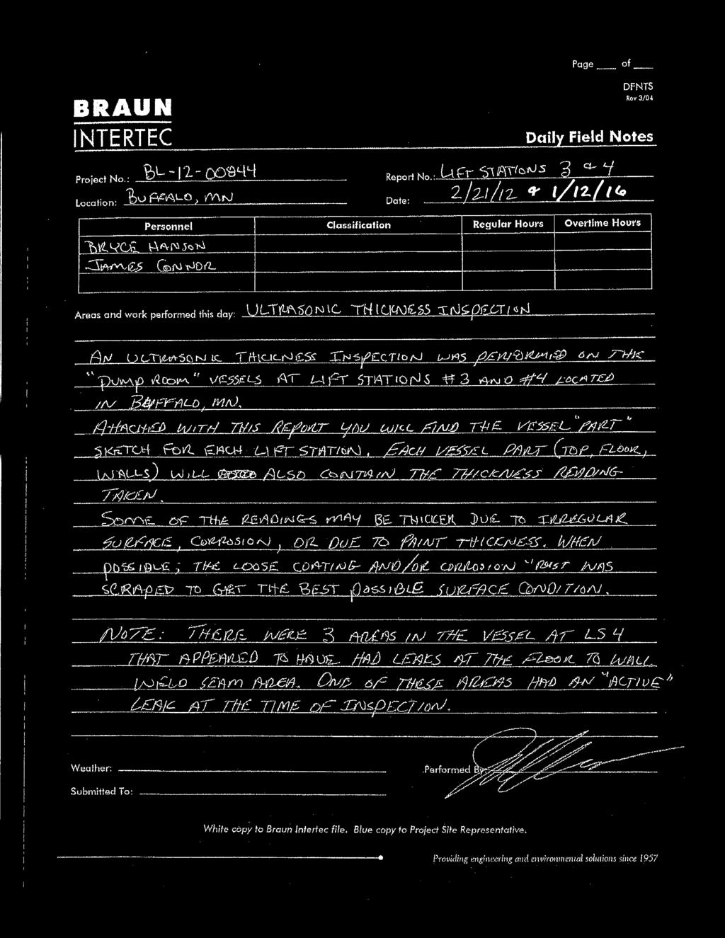
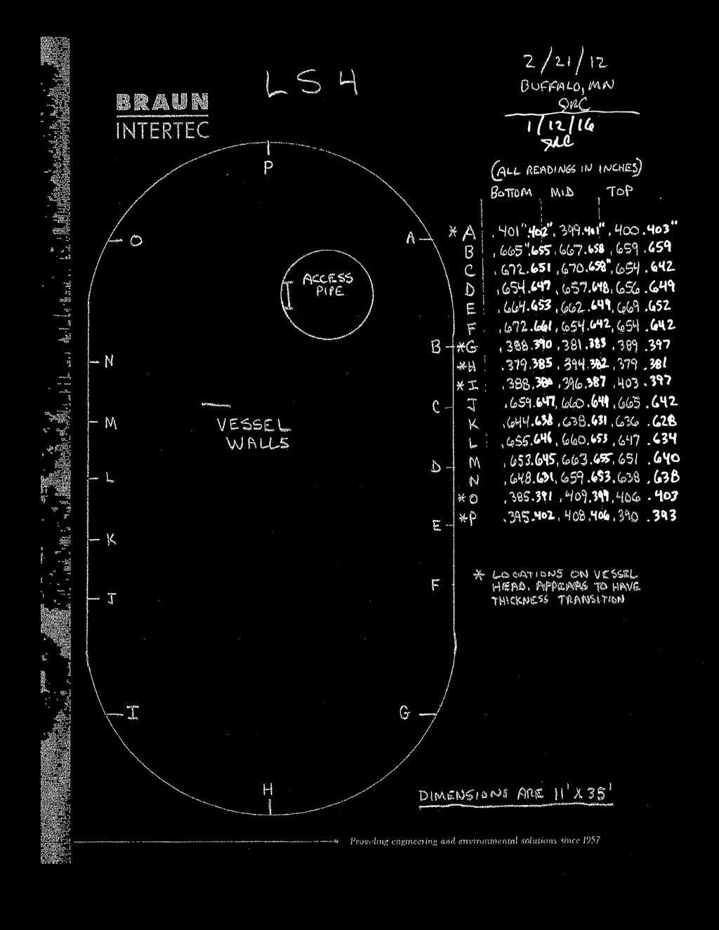
24 TABLE OF CONTENTS A. INTRODUCTION... B. INSPECTION METHODS... C. EVALUATION SUMMARY LIFT STATION #3... D. EVALUATION SUMMARY LIFT STATION #4... E. RECOMMENDATIONS... F. SUMMARY...3 Photos of Lift Stations #3 and #4 Braun Intertec Ultrasonic Thickness Inspection Notes from 0 and 06 City of Buffalo, Minnesota W3.088 Lift Stations #3 and #4 Inspection and Evaluation Page i Prepared by Bolton & Menk, Inc.
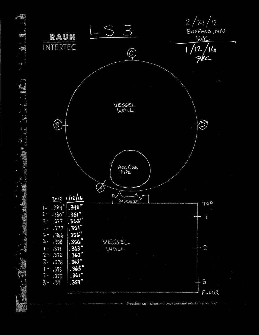
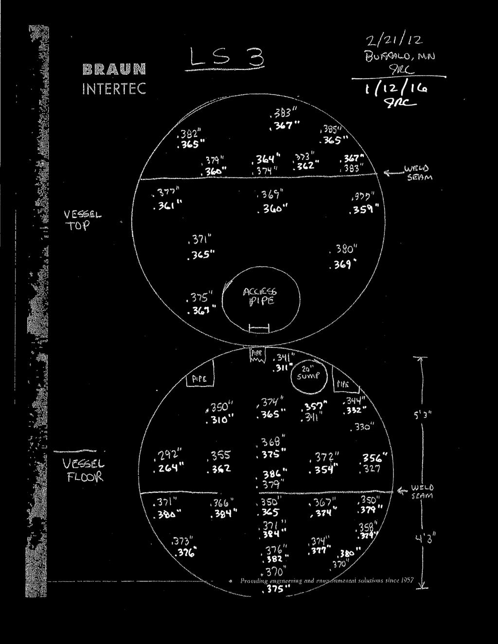
25 A. INTRODUCTION An inspection and evaluation was performed on lift stations #3 and #4, both located in Buffalo, Minnesota. The inspection and evaluation was performed on January, 06 as a follow up to the similar type evaluation with report provided in February 0. The areas observed were below the ground level at approximately 30 feet depth. The lift stations were in operation during the time of observations. B. INSPECTION METHODS A visual inspection and evaluation was performed on the interior portion of the lift stations. The inspections performed gathered steel wall thickness measurements and general observations of the interior protective coating conditions. An ultrasonic thickness gauge was used to determine the steel shell wall, floor, and ceiling wall thicknesses. Steel thicknesses readings were achieved through both the existing protective coating and on bare steel substrate. Some of the readings may vary slightly due to rough surfaces (interior and exterior), corrosion, and thick coatings. However, the differences should be minimal and should not affect the type of data to be collected when compared to the data collected in February of 0. The previous inspection report from February 0 was provided for reading comparison. C. EVALUATION SUMMARY LIFT STATION #3 Steel Thicknesses: The ultrasonic thickness readings taken in Lift Station #3 were recorded (in red) next to the original readings taken and recorded on the February 0 report. This report is attached. The readings varied slightly by approximately.00 to.030 in thickness. A portion of this difference in thickness could have been variations due to the surface condition as described above and/or uneven surfaces on the opposite side caused by external corrosion. From the data received during the inspection, there appears to be a very minimal loss (approximately.00 ) due to corrosion since the original evaluation in 0. General Coating Observations (#3): The protective coatings are in fair to poor condition. The floor is in poor condition and exhibits severe corrosion with complete coating failure in several areas. The walls and ceiling are in fair to poor condition with City of Buffalo, Minnesota W3.088 Page Lift Stations #3 and #4 Inspection and Evaluation Prepared by Bolton & Menk, Inc.
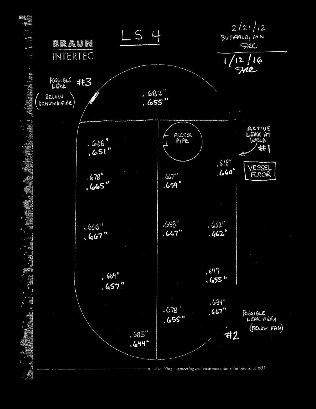
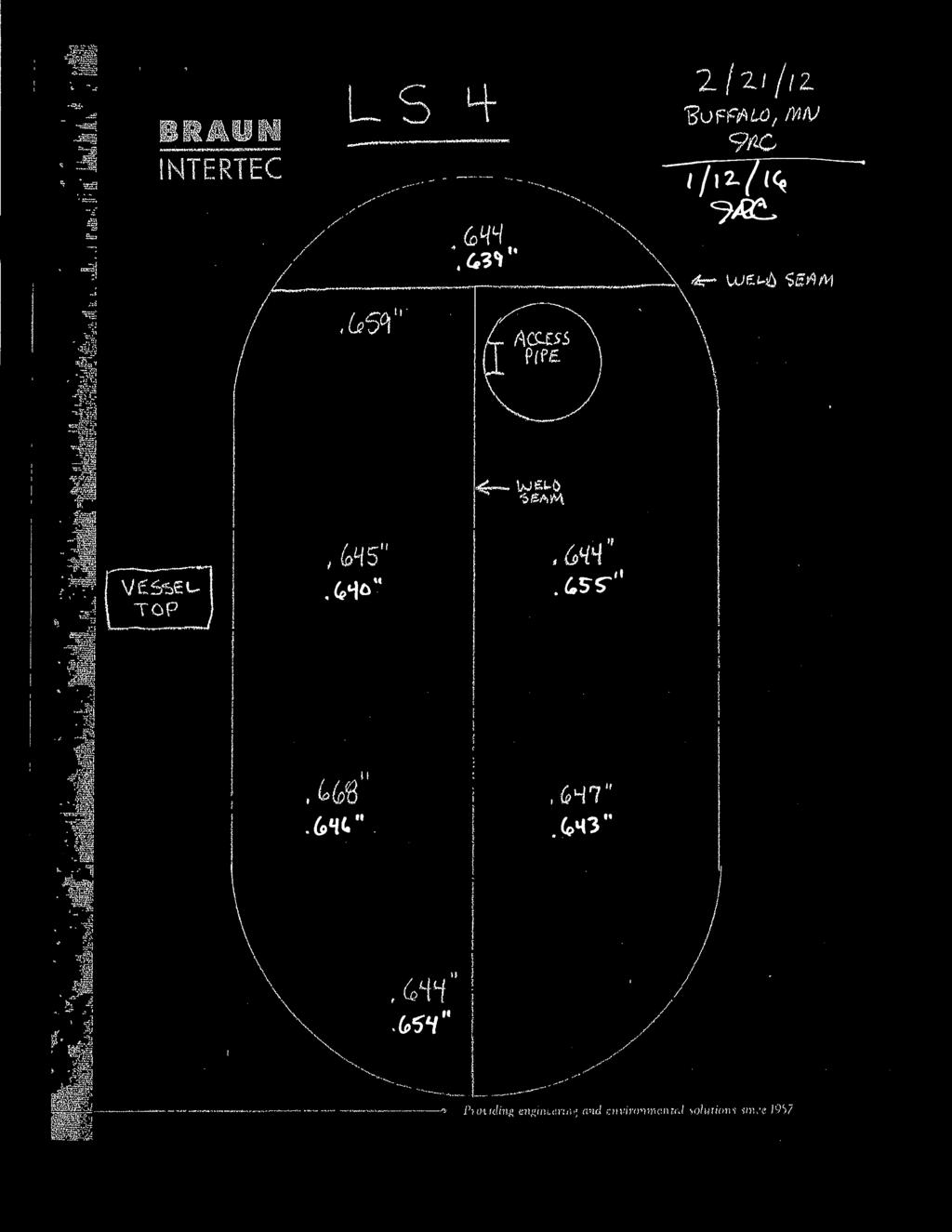
26 areas of visible corrosion. The access pipe coating is in fair to poor condition. See attached photos for current visual coating appearance conditions. D. EVALUATION SUMMARY LIFT STATION #4 Steel Thicknesses: The ultrasonic thickness readings taken in Lift Station #4 were also recorded next to the original readings taken and recorded in the February 0 report. Again, the readings appeared to have varied slightly in thickness due to surface conditions. From the data received during the inspection, there appears to be a very minimal loss (approximately ) due to corrosion since the original evaluation in 0. General Coating Observations (#4): The protective coatings are in fair condition; however, there are a few small spots of coating failure. These areas (approximately three) are all at the intersection where the shell wall meets the floor. One area presents a very minor but active through wall leak. The floor, wall, and ceiling are all in fair condition. The coatings on the piping, pumps, and valves are in fair condition. There are a few coating failures on the piping/equipment. See attached photos for present visual coating appearance conditions. E. RECOMMENDATIONS Interior Wet: Based on the information provided from the 0 evaluation report and in comparison with the results of the present (06) ultrasonic thickness measurement evaluation of the steel wall, it appears evident by the differences that there is minimal steel wall section loss. This applies to both the #3 and #4 lift stations. It is recommended that the steel wall be monitored at regular intervals for visual appearance and ultrasonic measurement for determining further section loss. There is one area (#) in Lift Station #4 that presents a through wall leak. It is recommended that this area be repaired by welding, or be covered by welding a steel plate over the leak. The protective coatings on the interior of Lift Station #3 are in fair to poor condition. It is recommended that these protective coatings be completely removed and replaced. City of Buffalo, Minnesota W3.088 Page Lift Stations #3 and #4 Inspection and Evaluation Prepared by Bolton & Menk, Inc.
27 The protective coatings on the interior of Lift Station #4 are in fair condition; however, there are a few small areas of coating failure. It is recommended that these areas exhibiting coating failure receive coating spot repair at the time of weld repair. F. SUMMARY Given the results from the ultrasonic thickness measurements, it is recommended that the steel wall thicknesses be monitored and compared every 3-5 years. Given the overall coating conditions and the amount of corrosion of the interior of the lift stations, it is recommended that Lift Station #3 receive a coating rehabilitation in the next - years or that plans be made to completely replace the lift station steel can structure in the near future. Additionally, it is recommended that the active leak and coating spot repairs in Lift Station #4 be performed in the next - years. Both rehabilitation projects could be performed simultaneously. Inspection and Report Performed By: Report Reviewed By: James R. Connor NACE Certified Coatings Inspector #33440 AWS Certified Welding Inspector #906 Bolton & Menk, Inc. Justin Kannas, P.E. Project Manager Principal Engineer License No Bolton & Menk, Inc. City of Buffalo, Minnesota W3.088 Page 3 Lift Stations #3 and #4 Inspection and Evaluation Prepared by Bolton & Menk, Inc.
 Subject: Site view of Lift Station #3 MN) Subject:")

28 Photograph #: Date: January, 06 Lift Station #3 (Buffalo, MN) Subject: Site view of Lift Station #3 Photograph #: Date: January, 06 Lift Station #3 (Buffalo, MN) Subject: View of piping, valves, pump, etc. and shell wall and floor
 Subject: View of piping, valves, pump, etc.")
 Subject: View of pipe and")
29 Photograph #: 3 Date: January, 06 Lift Station #3 (Buffalo, MN) Subject: View of piping, valves, pump, etc. and shell wall and floor Photograph #: 4 Date: January, 06 Lift Station #3 (Buffalo, MN) Subject: View of pipe and shell wall
 Subject: View of piping and shell")
 Subject: View of")
30 Photograph #: 5 Date: January, 06 Lift Station #3 (Buffalo, MN) Subject: View of piping and shell wall and floor Photograph #: 6 Date: January, 06 Lift Station #3 (Buffalo, MN) Subject: View of sump pump
 Subject: Close up view of chamber")
 Subject: View of pipe")
31 Photograph #: 7 Date: January, 06 Lift Station #3 (Buffalo, MN) Subject: Close up view of chamber floor corrosion Photograph #: 8 Date: January, 06 Lift Station #3 (Buffalo, MN) Subject: View of pipe at ceiling
 Subject: View of chamber")

32 Photograph #: 9 Date: January, 06 Lift Station #3 (Buffalo, MN) Subject: View of chamber ceiling Photograph #: 0 Date: January, 06 Lift Station #3 (Buffalo, MN) Subject: View of chamber ceiling
 Subject: View of access pipe from chamber (below) MN)")
")
33 Photograph #: Date: January, 06 Lift Station #3 (Buffalo, MN) Subject: View of access pipe from chamber (below) Photograph #: Date: January, 06 Lift Station #3 (Buffalo, MN) Subject: View of access pipe and ladder from chamber (below)
 Subject: Site view of Lift Station #4 Photograph #:")

34 Photograph #: Date: March 9, 06 Lift Station #4 (Buffalo, MN) Subject: Site view of Lift Station #4 Photograph #: Date: January, 06 Lift Station #4 (Buffalo, MN) Subject: View of ceiling, walls, equipment, piping, pumps, etc in chamber.

")
35 Photograph #: 3 Date: January, 06 Lift Station #4 (Buffalo, MN) Subject: View of floor, walls, equipment, piping, pumps, etc in chamber. Photograph #: 4 Date: January, 06 Lift Station #4 (Buffalo, MN) Subject: View of chamber area at dehumidifier (possible leak #3)
 Subject: View of floor area in")
 Subject: View of ceiling")
36 Photograph #: 5 Date: January, 06 Lift Station #4 (Buffalo, MN) Subject: View of floor area in chamber Photograph #: 6 Date: January, 06 Lift Station #4 (Buffalo, MN) Subject: View of ceiling area in chamber
 Subject: View of heater and electrical box")
 Subject: View of secondary/alternate")
37 Photograph #: 7 Date: January, 06 Lift Station #4 (Buffalo, MN) Subject: View of heater and electrical box in chamber Photograph #: 8 Date: January, 06 Lift Station #4 (Buffalo, MN) Subject: View of secondary/alternate access tube
 Subject: View of access tube and ladder")
 Subject: Area of leak # (note: evidence")
38 Photograph #: 9 Date: January, 06 Lift Station #4 (Buffalo, MN) Subject: View of access tube and ladder Photograph #: 0 Date: January, 06 Lift Station #4 (Buffalo, MN) Subject: Area of leak # (note: evidence of active leak)
 Subject: Close up of active leak #")

39 Photograph #: Date: January, 06 Lift Station #4 (Buffalo, MN) Subject: Close up of active leak # Photograph #: Date: January, 06 Lift Station #4 (Buffalo, MN) Subject: View at area of possible leak #
 Subject: Close up view of possible")

40 Photograph #: 3 Date: January, 06 Lift Station #4 (Buffalo, MN) Subject: Close up view of possible leak # Photograph #: 4 Date: January, 06 Lift Station #4 (Buffalo, MN) Subject: Close up view of possible leak #
 Subject: View at area of")
 Subject: View")
41 Photograph #: 5 Date: January, 06 Lift Station #4 (Buffalo, MN) Subject: View at area of possible leak #3 Photograph #: 6 Date: January, 06 Lift Station #4 (Buffalo, MN) Subject: View of sump pump
 Subject: View of sump pump")

42 Photograph #: 7 Date: January, 06 Lift Station #4 (Buffalo, MN) Subject: View of sump pump Photograph #: 8 Date: January, 06 Lift Station #4 (Buffalo, MN) Subject: View of sump pump and leaking valve
 Subject: Close up view of leaking valve")
 Subject: View of chamber ceiling and walls")
43 Photograph #: 9 Date: January, 06 Lift Station #4 (Buffalo, MN) Subject: Close up view of leaking valve Photograph #: 0 Date: January, 06 Lift Station #4 (Buffalo, MN) Subject: View of chamber ceiling and walls near access pipe

44
45
46
47

48
49
Appendix C Capital Improvement Program Project Descriptions and Details
 Appendix C Capital Improvement Program Project Descriptions and Details GIG HARBOR WW COMP PLAN DRAFT CAPITAL IMPROVEMENT PROGRAM LIFT STATION COST ESTIMATE Lift Station 1 Item Qty Units Unit Cost Extended
City of Grand Island Tuesday, October 10, 2017 Council Session
 City of Grand Island Tuesday, October 10, 2017 Council Session Item G-12 #2017-276 - Approving Change Order No. 1 for Lift Station No. 20 Upgrade and Force Main Rehabilitation & Lift Station No. 14 Abandonment;
Chapter 8.0 PROPOSED CAPITAL IMPROVEMENT PROGRAM
 Chapter 8.0 PROPOSED CAPITAL IMPROVEMENT PROGRAM This chapter presents the proposed Capital Improvement Program (CIP) for the District based on the findings of this Master Plan. The Master Plan primarily
City of Grand Forks Staff Report
 City of Grand Forks Staff Report Committee of the Whole December 1, 016 City Council December 19, 016 Agenda Item: Bids for City Project No. 7551 Lift Station No. 17 & 17A Rehabilitation Submitted by:
Public Information Centre
 Junction Street Wastewater Pumping Station & Forcemain Schedule B Municipal Class Environmental Assessment Study Public Information Centre June 28, 2017. 6:00 to 8:00 pm. The Burlington Performing Arts
Rosedale Sanitary Sewer Feasibility Review Report
 Rosedale Sanitary Sewer Feasibility Review Report Submitted by: WEDLER ENGINEERING LLP 201 9300 Nowell Street Chilliwack BC V2P 4V7 Phone: 604 792 0651 Wedler File No: C13 5032/A December 6, 2013 STATEMENT
City of St. Pete Beach Model Capacity Report Addendum
 Model Capacity Report - Addendum City of St. Pete Beach Model Capacity Report Addendum Prepared for: City of St. Pete Beach 155 Corey Avenue St. Pete Beach, FL 33706 Prepared By: Kimley-Horn and Associates,
FEASIBILITY REPORT. 65 th STREET TRUNK WATER MAIN IMPROVEMENTS INVER GROVE HEIGHTS MINNESOTA DAKOTA COUNTY. October 2, 2017
 FEASIBILITY REPORT 65 th STREET TRUNK WATER MAIN IMPROVEMENTS INVER GROVE HEIGHTS MINNESOTA DAKOTA COUNTY October 2, 2017 Prepared for: City of Inver Grove Heights 8150 Barbara Avenue Inver Grove Heights,
Appendix Technical Memorandum PS-1 on Pumping Stations Condition Assessment
 Appendix 4-28 Technical Memorandum PS-1 on Pumping Stations Condition Assessment TECHNICAL MEMORANDUM PS-1 March 8, 2013 To Copy to From Town of Falmouth, MA File; Project Team Nathan C. Weeks, P.E., BCEE
City Hall 539 Phoenix Street South Haven, Michigan Telephone (269) Fax (269)
 Fax (269)") City of South Haven City Hall 539 Phoenix Street South Haven, Michigan 49090-1499 Telephone (269) 637-0700 Fax (269) 637-5319 Dunkley and Black River Infrastructure Improvements Dunkley - Dyckman Avenue
City of South Haven City Hall 539 Phoenix Street South Haven, Michigan 49090-1499 Telephone (269) 637-0700 Fax (269) 637-5319 Dunkley and Black River Infrastructure Improvements Dunkley - Dyckman Avenue
Pump Station 7 Improvements
 Project Business Case ID: C04 2/18/2017 Pump Station 7 Project Purpose: The purpose of this project is to ensure that Pump Station 7 continues to operate in an efficient and effective manner following
Section 5 - Operations and Maintenance Program
 Section 5 - Operations and Maintenance Program A. Introduction The intent of this section of the SSMP is to describe the current operation of the City s wastewater collection system. There are five areas
BOARD OF SUPERVISORS BUSINESS MEETING ACTION ITEM. Design Endorsement for Sterling Boulevard Extension
 Date of Meeting: July 20, 2017 # 6 BOARD OF SUPERVISORS BUSINESS MEETING ACTION ITEM SUBJECT: ELECTION DISTRICT: CRITICAL ACTION DATE: STAFF CONTACTS: Design Endorsement for Sterling Boulevard Extension
SUBTOTAL SITE WORK & DEMOLITION (UTILITIES) $180, $348, $319,943.71
 $180, $348, $319,943.71") BASE BID 1.00 GENERAL CONDITIONS 1.01 Mobilization (Maximum 5% of Base Bid) LS 1 84,000.00 $ 84,000.00 100,000.00 $ 100,000.00 85,000.00 $ 85,000.00 1.02 Bonding, Insurance, Permits (including Plumbing,
BASE BID 1.00 GENERAL CONDITIONS 1.01 Mobilization (Maximum 5% of Base Bid) LS 1 84,000.00 $ 84,000.00 100,000.00 $ 100,000.00 85,000.00 $ 85,000.00 1.02 Bonding, Insurance, Permits (including Plumbing,
City of Grand Island Tuesday, February 13, 2018 Council Session
 City of Grand Island Tuesday, February 13, 2018 Council Session Item G-7 #2018-34 - Approving Certificate of Final Completion for the Construction of North Interceptor Phase I; Project No. 2012-S-6 Staff
GCG ASSOCIATES, INC. PROFESSIONAL CIVIL ENGINEERS AND LAND SURVEYORS 84 Main Street Wilmington, Massachusetts 01887
 GCG ASSOCIATES, INC. PROFESSIONAL CIVIL ENGINEERS AND LAND SURVEYORS 84 Main Street Wilmington, Massachusetts 01887 Phone: (978) 657-9714 Fax: (978) 657-7915 December 31,2.012 Mr. Charles Aspinwall Town
Bi-County Transitway/ Bethesda Station Access Demand Analysis
 Bi-County Transitway/ Bethesda Station Access Demand Analysis Prepared for: Washington Metropolitan Area Transit Authority Office of Planning and Project Development May 2005 Prepared by: in conjunction
CNG FUELING STATION INITIAL STUDY FULLERTON JOINT UNION HIGH SCHOOL DISTRICT. Appendices
 CNG FUELING STATION INITIAL STUDY FULLERTON JOINT UNION HIGH SCHOOL DISTRICT Appendices Appendix F Parking Study April 2016 CNG FUELING STATION INITIAL STUDY FULLERTON JOINT UNION HIGH SCHOOL DISTRICT
FREQUENTLY ASKED QUESTIONS
 THE PROJECT Last updated on 9/8/16 FREQUENTLY ASKED QUESTIONS What s happening on Highway 169? The Minnesota Department of Transportation (MnDOT) is planning to rebuild and repair the infrastructure on
Welcome. Highway 23 Gap New London to Paynesville. Open House. - Please Sign In -
 Highway Gap New London to Paynesville Welcome Highway Gap New London to Paynesville Open House - Please Sign In - There is no formal presentation, but representatives are available to answer your questions.
Open House. Highway212. Meetings. Corridor Access Management, Safety & Phasing Plan. 5:30 to 6:30 p.m. - Southwest Corridor Transportation Coalition
 Welcome Meetings 5:30 to 6:30 p.m. - Southwest Corridor Transportation Coalition 6:30 to 8:00 p.m. - Open House Why is Highway 212 Project Important? Important Arterial Route Local Support Highway 212
EQUAL DISTRIBUTION OF WASTEWATER USING LOW-PRESSURE DISTRIBUTION Larry D. Stephens, P.E. *
 EQUAL DISTRIBUTION OF WASTEWATER USING LOW-PRESSURE DISTRIBUTION Larry D. Stephens, P.E. * INTRODUCTION Experience with onsite systems has proven that equal application of wastewater over the entire soil
CAPITAL FUND 9510 STREET & SIDEWALK IMPROVEMENTS FIVE-YEAR CAPITAL IMPROVEMENT PROGRAM FISCAL YEARS
 9510 STREET & SIDEWALK IMPROVEMENTS FIVE-YEAR CAPITAL IMPROVEMENT PROGRAM FISCAL YEARS 2019-2023 9510 STREET & SIDEWALK IMPROVEMENTS - 01 STREET AND SIDEWALK MAINTENANCE PROGRAM $1,250,000 $0 $1,250,000
FREQUENTLY ASKED QUESTIONS
 THE PROJECT Last updated on 2/19/16 FREQUENTLY ASKED QUESTIONS What s happening on Highway 169? The Minnesota Department of Transportation (MnDOT) is planning to rebuild and repair the infrastructure on
Tom Parece, Reggie Donoghue and Mike Domenica P. R. Ammann
 To: From: Subject: Tom Parece, Reggie Donoghue and Mike Domenica P. R. Ammann TM #7 A STEP Effluent Has a Big Cost Advantage over a Gravity for Downtown Orleans Date: January 12, 2017 Summary In its preliminary
FINAL UTILITY REPORT Eastcreek Farm Thornton, CO
 FINAL UTILITY REPORT Eastcreek Farm Thornton, CO October 14, 2016 JN: 13049 Prepared for: York 80, LLC 12460 1 st Street Eastelake, CO 80614 P: 303.457.2966 Prepared by: Jansen Strawn Consulting Engineers
Todd Carlson Program Coordinator Engineering MMSD PP I/I Summit 2.0 October 15,
 Todd Carlson Program Coordinator Engineering MMSD PP I/I Summit 2.0 October 15, 2015 1 North Shore of Lake Superior 883 feet of Elevation Aging Sanitary/Storm Sewer System dating back to 1880 s Second
ACTION TRANSMITTAL No
 Transportation Advisory Board of the Metropolitan Council of the Twin Cities DATE: January 4, 2016 TO: ACTION TRANSMITTAL No. 2016-19 TAC Funding and Programming Committee PREPARED BY: Joe Barbeau, Senior
JCP&L Verbatim Response to Middletown Township s Questions
 JCP&L Verbatim Response to Middletown Township s Questions Township officials sent 13 questions about the proposed Monmouth County Reliability Project to JCP&L on June 10 th. JCP&L provided direct responses
ATTACHMENT #1. TO: Patricia delabruere DATE: May 5, 2015 JNU Airport Manager
 MEMO TO: Patricia delabruere DATE: May 5, 2015 JNU Airport Manager FROM: RE: Catherine Fritz, AIA JNU Airport Architect ARFF Project Formulation The Airport Board s funding authorization on February 11,
Subarea Study. Manning Avenue (CSAH 15) Corridor Management and Safety Improvement Project. Final Version 1. Washington County.
 Corridor Management and Safety Improvement Project. Final Version 1. Washington County.") Subarea Study Manning Avenue (CSAH 15) Corridor Management and Safety Improvement Project Final Version 1 Washington County June 12, 214 SRF No. 138141 Table of Contents Introduction... 1 Forecast Methodology
Subarea Study Manning Avenue (CSAH 15) Corridor Management and Safety Improvement Project Final Version 1 Washington County June 12, 214 SRF No. 138141 Table of Contents Introduction... 1 Forecast Methodology
Date of Meeting: April 3, 2015
 PMT MEETING MINUTES RE: Brainerd Lakes Regional Airport Utility Extension Preliminary Design/Scoping Phase Brainerd, MN Date of Meeting: April 3, 2015 Project Manager: Scott Hedlund Time of Meeting: 10:00
City of Palo Alto (ID # 6416) City Council Staff Report
 City Council Staff Report") City of Palo Alto (ID # 6416) City Council Staff Report Report Type: Informational Report Meeting Date: 1/25/2016 Summary Title: Update on Second Transmission Line Title: Update on Progress Towards Building
City of Palo Alto (ID # 6416) City Council Staff Report Report Type: Informational Report Meeting Date: 1/25/2016 Summary Title: Update on Second Transmission Line Title: Update on Progress Towards Building
Rolling Road (Route 638) Widening Project
 Widening Project") Rolling Road (Route 638) Widening Project From: 0.369 Mile North of Fairfax County Parkway (Route 286) To: Old Keene Mill Road (Route 644) State Project No. 0638-029-156, P104, R204, C504; UPC 5559 Public
Rolling Road (Route 638) Widening Project From: 0.369 Mile North of Fairfax County Parkway (Route 286) To: Old Keene Mill Road (Route 644) State Project No. 0638-029-156, P104, R204, C504; UPC 5559 Public
City of Grand Forks Staff Report
 City of Grand Forks Staff Report Service/Safety Committee December 15, 2015 City Council December 21, 2015 Agenda Item: Amendment No. 1 to Engineering Services Agreement with CPS for City Project No. 7143,
City of Freeport Water & Sewer Capital Improvement Program FY2019-FY2024
 City of Freeport Water & Sewer Capital Improvement Program FY2019-FY2024 Current Issues $210 million in depreciated water & sewer assets are in need of replacement Many items: Production Wells, Treatment
To: File From: Adrian Soo, P. Eng. Markham, ON File: Date: August 18, 2015
 Memo To: From: Adrian Soo, P. Eng. Markham, ON : 165620021 Date: Reference: E.C. Row Expressway, Dominion Boulevard Interchange, Dougall Avenue Interchange, and Howard 1. Review of Interchange Geometry
REQUEST FOR COUNCIL ACTION. List of Exhibits A. Project Plan Set B. Bolton & Menk Proposal for Engineering / Inspection Services
 Item #08 - CC Agenda - 05/2/2016 [Page 1 of 5] REQUEST FOR COUNCIL ACTION : May 2, 2016 ITEM NO: 8 Department Approval: Administrator Reviewed: Agenda Section: Name Adam Edwards JML Public Works Director/
CTA Capital Construction Update May 17, 2007
 Block 37 Signals Project Brown Line Howard CTA Capital Construction Update May 17, 2007 1 Capital Construction Update Agenda Howard Station Reconstruction Brown Line Capacity Expansion Project Block 37
Truck Traffic Impact Analysis
 Truck Traffic Impact Analysis FOR Proposed Demolition Project AT 3300 Panorama Drive Morro Bay, CA Prepared for Rhine LP & CVI Group, LLC Prepared by 1998 Santa Barbara Avenue, Suite 200 San Luis Obispo,
ANDERSON, ECKSTEIN AND WESTRICK, INC.
 ANDERSON, ECKSTEIN AND WESTRICK, INC. 51301 Schoenherr Civil Engineers Road, Shelby Township, Michigan 48315 Surveyors Architects 586-726-1234 Mr. Matthew Tepper City of Grosse Pointe Farms 90 Kerby Road
TRAFFIC IMPACT STUDY. USD #497 Warehouse and Bus Site
 TRAFFIC IMPACT STUDY for USD #497 Warehouse and Bus Site Prepared by: Jason Hoskinson, PE, PTOE BG Project No. 16-12L July 8, 216 145 Wakarusa Drive Lawrence, Kansas 6649 T: 785.749.4474 F: 785.749.734
Right-of-Way Obstruction Permit Fee Structure Minneapolis Department of Public Works May 10, 2001
 Right-of-Way Obstruction Permit Fee Structure Minneapolis Department of Public Works May 10, 2001 Revised April 5, 2005 Revised January 27, 2006 Prepared by: Steve Collin, Engineer 2.5 Revised by Douglas
CONCEPTUAL UTILITY REPORT FOR THE CANYONS PHASE 1 CITY OF CASTLE PINES, CO
 CONCEPTUAL UTILITY REPORT FOR THE CANYONS PHASE 1 CITY OF CASTLE PINES, CO PREPARED FOR: SHEA HOMES 9380 STATION ST., SUITE 600 LONE TREE, CO 80124 PHONE: 303-791-8180 CONTACT: RYAN MCDERMED PREPARED BY:
Wentzville Parkway South Phase 2 & 2A
 Wentzville Parkway South Phase 2 & 2A Sponsor Wentzville Project No. RB18-000034 Project Type New Road TOTAL FUNDING Phase 2 Total County Sponsor Federal $10,000,000 $8,000,000 $2,000,000 $0 Phase 2A Total
STATE OF RHODE ISLAND AND PROVIDENCE PLANTATIONS ENERGY FACILITY SITING BOARD
 STATE OF RHODE ISLAND AND PROVIDENCE PLANTATIONS ENERGY FACILITY SITING BOARD In re : : Docket No. SB-00-0 () : Testimony of David M. Campilii, P.E. June, 00 PROV-- 0 0 TESTIMONY OF DAVID M. CAMPILII,
Robert L. Griffin, PE. Mark C. Boland, PE. C. Russell McDaniel, PE. President / Chief Operations Officer Shield Engineering, Inc.
 Robert L. Griffin, PE President / Chief Operations Officer Shield Engineering, Inc. Mark C. Boland, PE Principal Engineer Shield Engineering, Inc. C. Russell McDaniel, PE Director Environmental Engineering,
Effective SSO Elimination Indian Lake is a Beautiful Place Again
 Effective SSO Elimination Indian Lake is a Beautiful Place Again Henry Mac McCauley, P.E. Ronald J. Jacob Keith A. Radick OWEA 2012 Annual Conference June 20, 2012 Aurora, Ohio Introduction Additional
I-820 (East) Project Description. Fort Worth District. Reconstruct Southern I-820/SH 121 Interchange
 Project Description. Fort Worth District. Reconstruct Southern I-820/SH 121 Interchange") I-820 (East) Project Description Fort Worth District Reconstruct Southern I-820/SH 121 Interchange I-820 from approximately 2,000 feet north of Pipeline Road/Glenview Drive to approximately 3,200 feet
I-820 (East) Project Description Fort Worth District Reconstruct Southern I-820/SH 121 Interchange I-820 from approximately 2,000 feet north of Pipeline Road/Glenview Drive to approximately 3,200 feet
Capital Improvement Program
 7 INTRODUCTION The (CIP) involves the compilation of a schedule of recommended development projects, and their probable costs, that are based on the fi ndings of the demand forecasts and facility requirements
Table of Contents INTRODUCTION... 3 PROJECT STUDY AREA Figure 1 Vicinity Map Study Area... 4 EXISTING CONDITIONS... 5 TRAFFIC OPERATIONS...
 Crosshaven Drive Corridor Study City of Vestavia Hills, Alabama Table of Contents INTRODUCTION... 3 PROJECT STUDY AREA... 3 Figure 1 Vicinity Map Study Area... 4 EXISTING CONDITIONS... 5 TRAFFIC OPERATIONS...
STATE OF NEW HAMPSHIRE BEFORE THE NEW HAMPSHIRE PUBLIC UTILITIES COMMISSION RE: PENNICHUCK WATERWORKS, INC. DW 13-
 STATE OF NEW HAMPSHIRE BEFORE THE NEW HAMPSHIRE PUBLIC UTILITIES COMMISSION RE: PENNICHUCK WATERWORKS, INC. 2013 WATER INFRASTRUCTURE AND CONSERVATION ADJUSTMENT FILING DIRECT TESTIMONY OF DONALD L. WARE
EMERGING REQUIREMENTS
 Page of 0 EMERGING REQUIREMENTS EXTERNALLY INITIATED PLANT RELOCATIONS THESL distributes electricity to residential, commercial, and industrial customers via overhead and underground infrastructure. This
4.2 Series Station Option Description
 4.2 Series Station Option Description The series station proposal features a new set of side platforms constructed approximately 250 feet north of the existing platforms. The two new platforms would extend
STH 60 Northern Reliever Route Feasibility Study Report
 #233087 v3 STH 60 Northern Reliever Route Feasibility Study Report Washington County Public Works Committee Meeting September 28, 2016 1 STH 60 Northern Reliever Route Feasibility Study Hartford Area Development
4.0 TIER 2 ALTERNATIVES
 4.0 TIER 2 ALTERNATIVES The Tier 2 Alternatives represent the highest performing Tier 1 Alternatives. The purpose of the Tier 2 Screening was to identify the LPA utilizing a more robust list of evaluation
Population Trends. US 12 Corridor Performance
 Corridor Context The corridor runs over 81 miles from Willmar to the Twins Cities metropolitan area. It connects the Twin Cities and the cities of Montrose, Howard Lake, Cokato, Dassel, Litchfield, Atwater,
Bid Summary Still Creek Wastewater Improvements Phase III City Job No. 411-D November 21, 2013
 Bid Summary Still Creek Wastewater Improvements Phase III City Job No. 411-D4-1102 November 21, 2013 Doughtie Construction Co., Elliott Construction Dudley Construction Ltd. SUBTOTAL GENERAL ITEMS : $191,713.00
INSTALLATION GUIDE. Model #GB2 35/50 GPM Grease Interceptor For Indoor Use. Contents
 INSTALLATION GUIDE Model #GB2 35/50 GPM Grease For Indoor Use Contents Special Precautions............................................ 2 Getting to Know the GB2....................................... 3
INSTALLATION GUIDE. Model #GB1 20/25 GPM Grease Interceptor For Indoor Use. Contents
 INSTALLATION GUIDE Model #GB1 20/25 GPM Grease For Indoor Use Contents Special Precautions............................................ 2 Getting to Know the GB1........................................
Section 5. Manhole Inspection Report
 Section 5 Inspection Report Ypsilanti Community Utilities Authority Huron River Interceptor I/I Study Inspection Report Technical Memorandum December, 2008 Introduction Several manholes within the Huron
EMERGING REQUIREMENTS
 EB-00-0 Exhibit D Schedule Page of EMERGING REQUIREMENTS 0 EQUIPMENT STANDARDIZATION THESL plans, designs and constructs distribution system assets in accordance with approved standards. The standards
Spill Prevention Report Lift Station 1A. Prepared By:
 Spill Prevention Report Lift Station 1A Prepared By: Contents 1) Purpose... 3 2) General Information... 3 3) Report Certification and Approval... 3 4) Facility Description... 4 5) Summary and Leaks, Spills
STAFF REPORT. To: Planning Commission Meeting date: April 12, 2017 Item: UN Prepared by: Robert Eastman
 # 5 ) UN-15-17 LA SIERRA AUTO SALES SPECIAL USE PERMIT VEHICLE SALES PUBLIC HEARING STAFF REPORT To: Planning Commission Meeting date: April 12, 2017 Item: UN-15-17 Prepared by: Robert Eastman GENERAL
Plan and Profile for the Black Dog Natural Gas Pipeline Project Docket No. G002/GP
 414 Nicollet Mall Minneapolis, MN 55401 March 13, 2017 Daniel P. Wolf Executive Secretary Minnesota Public Utilities Commission 121 7 th Place East, Suite 350 St. Paul, MN 55101 Via Electronic Filing RE:
IMPROVEMENT CONCEPTS
 IMPROVEMENT CONCEPTS for the South Novato Transit Hub Study Prepared by: January 11, 2010 DKS Associates With Wilbur Smith Associates IMPROVEMENT CONCEPTS Chapter 1: Introduction 1. INTRODUCTION The strategic
Capital Improvement Plan Review
 City of Manhattan Beach Public Works Department Fiscal Year 2014/2015 2018/2019 Capital Improvement Plan Review Community Meeting: April 10, 2014 Objectives Creating the Capital Improvement Plan Funding
APPENDIX B Traffic Analysis
 APPENDIX B Traffic Analysis Rim of the World Unified School District Reconfiguration Prepared for: Rim of the World School District 27315 North Bay Road, Blue Jay, CA 92317 Prepared by: 400 Oceangate,
Oaks Commerce Center
 Mansour Edlin Consulting 1515 Mockingbird Lane Charlotte, NC 28209 Oaks Commerce Center Water & Sanitary Sewer Improvements Phase I - Concept Utility Plan Gravity Sanitary Sewer A1 Connect to Existing
INTERSECTION CONTROL EVALUATION
 INTERSECTION CONTROL EVALUATION Trunk Highway 22 and CSAH 21 (E Hill Street/Shanaska Creek Road) Kasota, Le Sueur County, Minnesota November 2018 Trunk Highway 22 and Le Sueur CSAH 21 (E Hill Street/Shanaska
MPO Staff Report Technical Advisory Committee: July 12, 2017
 MPO Staff Report Technical Advisory Committee: July 12, 2017 RECOMMENDED ACTION: 2 nd TAC Meeting with Kimley-Horn/WSB in Updating the Street/Highway Element of 2045 Metropolitan Transportation Plan. Matter
April 17, 2018 CITY OF BONNEY LAKE WATER PROJECTS. Geoff Dillard, P.E.
 April 17, 2018 CITY OF BONNEY LAKE WATER PROJECTS Geoff Dillard, P.E. HOW TO DECIDE? Council vested in making informed decisions which protect the City s assets and citizens Factors that influence decisions
AN UPDATE ON THE IMPLEMENTATION
 AN UPDATE ON THE IMPLEMENTATION OF THE STICKNEY, CALUMET AND NORTHSIDE WATER RECLAMATION PLANTS MASTER PLANS THOMAS E. KUNETZ Assistant Chief Engineer, Engineering Dep t. Metropolitan Water Reclamation
RTID Travel Demand Modeling: Assumptions and Method of Analysis
 RTID Travel Demand Modeling: Assumptions and Method of Analysis Overall Model and Scenario Assumptions The Puget Sound Regional Council s (PSRC) regional travel demand model was used to forecast travel
Bettendorf City Council Joint Use Sewer Administrative Consent Order February 4, 2013
 Bettendorf City Council Joint Use Sewer Administrative Consent Order February 4, 2013 History/Timeline Interceptor Sewers/Locations (approximately 13 miles) Strategy for Financial Plan, Plan of Action
ARLINGTON COUNTY, VIRGINIA
 ARLINGTON COUNTY, VIRGINIA County Board Agenda Item Meeting of April 24, 2004 DATE: April 14, 2004 SUBJECT: Arlington Boulevard (U.S. 50) Bridge Deck Replacement at Washington Boulevard - Overhead Utility
FINAL. Sound Transit Long-Range Plan Update. Issue Paper S.1: Tacoma Link Integration with Central Link. Prepared for: Sound Transit
 Sound Transit Long-Range Plan Update Issue Paper S.1: Tacoma Link Integration with Central Link Prepared for: Sound Transit Prepared by: Quade & Douglas, Inc. FINAL March 2005 Foreword This issue paper
DRAFT Design Study Report February 2015 Eagle River Traffic Mitigation Phase 1 MOA Project No Appendix D Utilities
 Appendix D Utilities This page intentionally left blank. Utilities There are numerous utilities present within the project area, including natural gas, sewer, water, electric, communications, and street
Agenda. Utility Undergrounding Strategies & Laguna Canyon Road Master Plan
 Utility Undergrounding Strategies & Laguna Canyon Road Master Plan January 17, 2017 City Council Meeting 2 Agenda Progress since March 2016 Status of undergrounding and road widening between El Toro Rd.
Evaluation Considerations and Geometric Nuances of Reduced Conflict U-Turn Intersections (RCUTs)
") Evaluation Considerations and Geometric Nuances of Reduced Conflict U-Turn Intersections (RCUTs) 26 th Annual Transportation Research Conference Saint Paul RiverCentre May 20, 2015 Presentation Outline
Evaluation Considerations and Geometric Nuances of Reduced Conflict U-Turn Intersections (RCUTs) 26 th Annual Transportation Research Conference Saint Paul RiverCentre May 20, 2015 Presentation Outline
Public Works Department
 Public Works Department SUBJECT: Consideration of two Resolutions concerning replacement of the Village s fuel system. AGENDA ITEM: 9.b.iii MEETING DATE: July 20, 2015 VILLAGE BOARD REPORT TO: Village
CTA Capital Construction Update December 12, 2006
 Red Line/Dan Ryan Blue Line Block 37 Washington Subsurface Station at Block 37 Block 37 Tracks Randolph Red Line Brown Line Howard CTA Capital Construction Update December 12, 2006 1 Capital Construction
SASD 2010 SYSTEM CAPACITY PLAN EXPANSION TRUNK SHEDS BR EAST RANCHO TRUNK SHED 2015 AMENDMENT
 SASD 2010 SYSTEM CAPACITY PLAN EXPANSION TRUNK SHEDS BR EAST RANCHO TRUNK SHED 2015 AMENDMENT Introduction This amendment summarizes the new near-term and buildout expansion trunk shed plans. Due to recent
EXCEPTION TO STANDARDS REPORT
 EXCEPTION TO STANDARDS REPORT PROJECT DESCRIPTION AND NEED The project is located in Section 6, Township 23 North, Range 9 East and Section 31 Township 24 North, Range 9 East, in the Town of Stockton,
Interstate Operations Study: Fargo-Moorhead Metropolitan Area Simulation Output
 NDSU Dept #2880 PO Box 6050 Fargo, ND 58108-6050 Tel 701-231-8058 Fax 701-231-6265 www.ugpti.org www.atacenter.org Interstate Operations Study: Fargo-Moorhead Metropolitan Area 2015 Simulation Output Technical
WOLVERINE TO BHP JANSEN NEW TRANSMISSION LINE PROJECT FALL 2017
 WOLVERINE TO BHP JANSEN NEW TRANSMISSION LINE PROJECT FALL 2017 TODAY WE LL TALK ABOUT Our challenges and how we re meeting them Why we re building this project Our planning process and considerations
Scope of Services January 26, Project Development and Conceptual Engineering for City of Lake Forest Amtrak Station
 203 North LaSalle Street, Suite 2100 Chicago, IL 60601 (312) 558-1345 Fax: (312) 346-9603 E-Mail: cquandel@quandelconsultants.com www.quandel.com Scope of Services January 26, 2010 Project Development
REQUEST FOR PROPOSALS FIRE HYDRANT MAINTENANCE SERVICES
 REQUEST FOR PROPOSALS FIRE HYDRANT MAINTENANCE SERVICES The City of Abbeville, South Carolina is soliciting sealed proposals for Fire Hydrant Maintenance Services. All proposals must be in writing and
STATE OF MINNESOTA OFFICE OF ADMINISTRATIVE HEARINGS FOR THE PUBLIC UTILITIES COMMISSION PUC DOCKET NO. E002/TL OAH DOCKET NO.
 Direct Testimony and Schedules Grant Stevenson STATE OF MINNESOTA OFFICE OF ADMINISTRATIVE HEARINGS FOR THE PUBLIC UTILITIES COMMISSION IN THE MATTER OF THE APPLICATION FOR A ROUTE PERMIT FOR THE PLEASANT
APPENDIX C1 TRAFFIC ANALYSIS DESIGN YEAR TRAFFIC ANALYSIS
 APPENDIX C1 TRAFFIC ANALYSIS DESIGN YEAR TRAFFIC ANALYSIS DESIGN YEAR TRAFFIC ANALYSIS February 2018 Highway & Bridge Project PIN 6754.12 Route 13 Connector Road Chemung County February 2018 Appendix
A NEW SPIN ON PUMP STATION TESTING AND ANALYIS: WHAT YOU WISH YOU KNEW ABOUT YOUR PUMP STATION
 ABSTRACT Zachary G. Purvis, PE Kimley-Horn and Associates, Inc. 3001 Weston Parkway Cary NC, 27513; 919-653-2963; zak.purvis@kimley-horn.com Wastewater collection system owners are becoming increasingly
February 17, 2015 File:
 February 17, 2015 File: 0433.0008.001 Village of Valemount Box 168, 735 Cranberry Lake Road Valemount, BC V0E 2Z0 Attention: Anne Yanciw, CAO RE: Lift Station Upgrade Cost Estimates The Village of Valemount
Interstate Operations Study: Fargo-Moorhead Metropolitan Area Simulation Results
 NDSU Dept #2880 PO Box 6050 Fargo, ND 58108-6050 Tel 701-231-8058 Fax 701-231-6265 www.ugpti.org www.atacenter.org Interstate Operations Study: Fargo-Moorhead Metropolitan Area 2025 Simulation Results
TORONTO TRANSIT COMMISSION REPORT NO.
 Form Revised: February 2005 TORONTO TRANSIT COMMISSION REPORT NO. MEETING DATE: October 24, 2012 SUBJECT: DOWNTOWN RAPID TRANSIT EXPANSION STUDY (DRTES) PHASE 1 STRATEGIC PLAN ACTION ITEM RECOMMENDATIONS
Wastewater Capacity Evaluation Update. January 7, 2019
 Wastewater Capacity Evaluation Update January 7, 2019 Future Wastewater Needs Decision Factors driving the decision Design-Permitting-Construction timeline Will take ±4 years to deliver a project Raleigh
Cordova Psychrophiles Bio-Digester. Benefit-Cost and Sensitivity Analysis
 Cordova Psychrophiles Bio-Digester Benefit-Cost and Sensitivity Analysis December 2012 Prepared by: Sohrab Pathan, Alejandra Villalobos Meléndez and Ginny Fay Institute of Social and Economic Research
Understanding the Inspection Process for Owners and Operators
 Underground Storage Tanks (UST s) Metal Integrity and Lining Inspections Understanding the Inspection Process for Owners and Operators Presented By: Robert L. McChan II General Manager/Senior Project Manager/Steel
Speed Evaluation Saw Mill Drive
 Speed Evaluation Saw Mill Drive Prepared for: Mount Laurel Township Burlington County, New Jersey Prepared by: Dana Litwornia Litwornia & Associates, Inc. Transportation, Traffic & Environmental Engineering
2017 Industrial Rail and Transportation Study. Becker, Minnesota
 2017 Industrial Rail and Transportation Study Becker, Minnesota BECKR 140932 August 2, 2017 2017 Industrial Rail and Transportation Study Becker, Minnesota SEH No. BECKR 140932 August 2, 2017 I hereby
Mountainland Association of Governments SPRINGVILLE-SPANISH FORK AREA TRANSPORTATION STUDY APRIL 2012
 Mountainland Association of Governments SPRINGVILLE-SPANISH FORK AREA TRANSPORTATION STUDY APRIL 2012 PLANNING FOR OUR FUTURE Planners with the Mountainland Association of Governments (MAG) have evaluated