DYWIDAG Marine Tie Rods Smooth Bars & Walings
|
|
|
- Robyn Mason
- 6 years ago
- Views:
Transcription

1 DYWIDAG Marine Tie Rods Smooth Bars & Walings
2 2
3 Contents General Information... 4 Fields of Applications... 4 Overview of Steel Grades... 5 Steel Properties... 5 Thread Creation... 6 Key Advantages of Rolled Threads... 6 ULS Tie Rod Design According to DIN EN Design Example... 9 Tie Rod Types Tie Rods with Upset and Rolled Threads acc. to EAU 2014 k t Tie Rods with Upset and Rolled Threads acc. to DIN EN Tie Rods with Rolled Threads acc. to DIN EN k t Eye Rods k t Tie Rod Connection Elements Turnbuckles for Tie Rods Couplers for Tie Rods Hinged Turnbuckles for Tie Rods Hexagonal Nuts* Domed Nuts* Shackle Joint for Tie Rods Rocker Plate for Tie Rods Threaded Rocker Plate for Tie Rods Universal Joints for Tie Rods Universal Joints at Waling for Tie Rods Tie Rod and Waling Joints Rear Plate for DSI 355 Tie Rods acc. to with k t 0.9 in S Rear Plate for DSI 460 Tie Rods acc. to with k t 0.9 in S Rear Plate for DSI 500 Tie Rods acc. to with k t 0.9 in S Rear Plate for DSI 720 Tie Rods T-Connections for Tie Rods* T-Connections in Combined Sheet Piling for Anchors* Typical Complete Tie Rod Systems Compensate for Shallow Angles of up to max Dead Man Combined Sheet Piling with Tubular Piles Combined Sheet Piling when using Grade DSI Anchors Connected to Tubular Piles Heavy-Duty Walls with Steel Sections Alternative Tubular Pile Connection Option Permitting Rotational Movement in all Directions Walings Waling Splice Joint Waling Bracket Waling Bolt with Head and Nut Waling Stud with two Nuts Appendix List of Standards and Directives


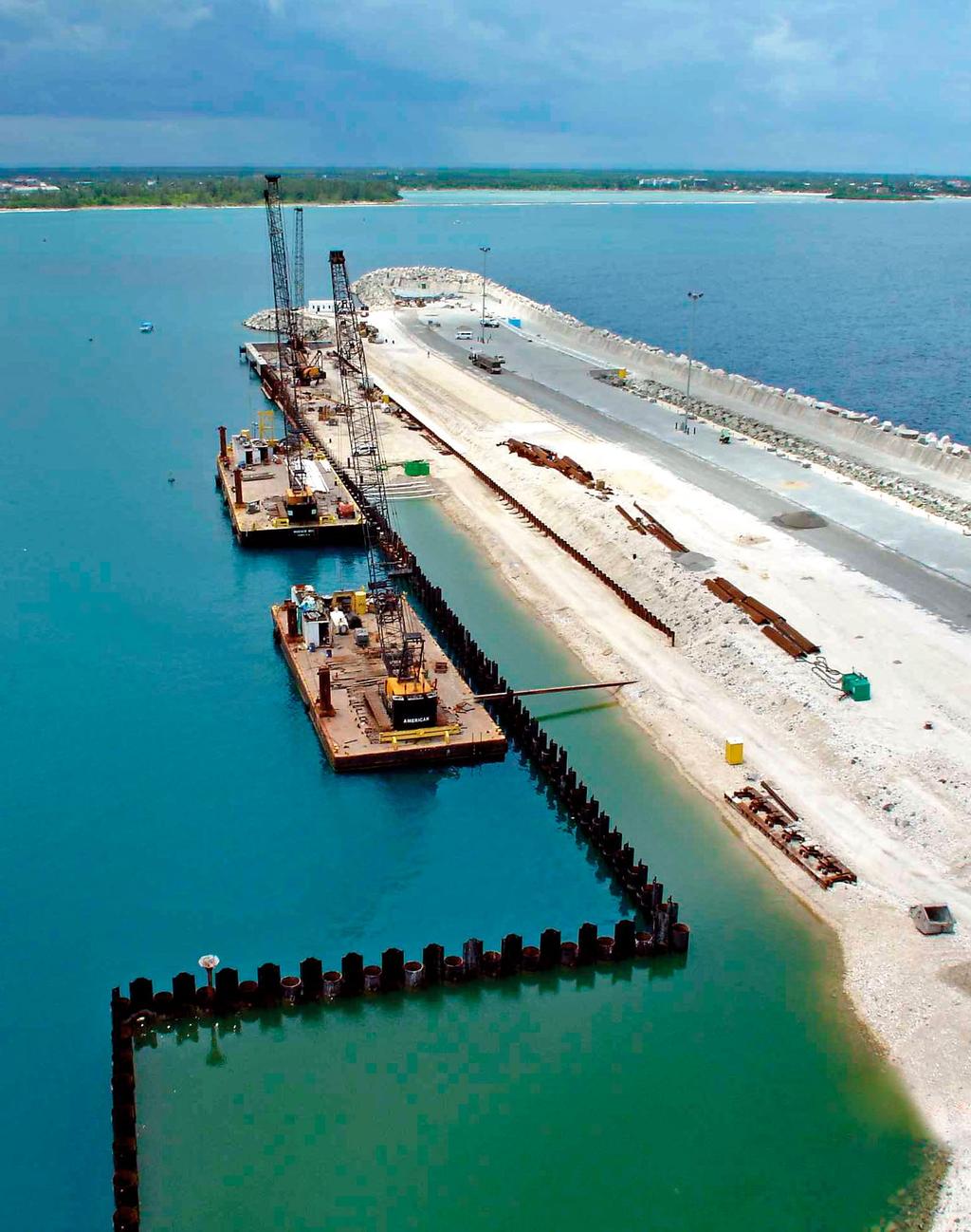
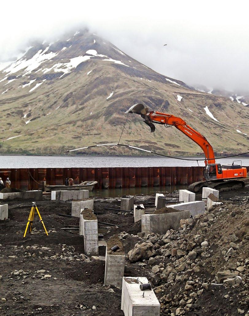
4 General Information Deep vertical shoring systems for marine structures such as sheet pile walls often require additional anchors which support a specific layer of the shoring wall. These anchors are also referred to as tie rods. They transfer the supportive forces at the connection with the sheet pile wall via tension loads either to a dead man anchorage or to the other shoring wall side in the case of wharf sheet pile boxes. Typically, the horizontal reaction forces are transferred from the sheet pile walls first to a waling beam and then from the waling system to the tie rods. This setup leads to a more distributed load transfer and an additional stiffening and alignment of the sheet pile wall compared to a solution in which the tie rods are directly connected to the sheet pile wall. Fields of Applications Tie Back Retaining Wall with Dead Man Bracing for Grade Separation Tie Rods for Sheet Pile Constructed Wharf Roadway Embankment Stabilization 4
![General Information Overview of Steel Grades Color Code Steel Grade Diameter F y F ua [ØD 1 ] [N/mm 2 ] [N/mm 2 ] DSI 355 M39 - M160 355 510 DSI 460 M39 - M160 460 640 Steel Characteristics The steel](/docs-images/78/78170121/images/5-0.jpg "used for our marine tie rods is based on the continuous casting method production leading to a homogenous resistance behavior over the entire steel section area.")

5 General Information Overview of Steel Grades Color Code Steel Grade Diameter F y F ua [ØD 1 ] [N/mm 2 ] [N/mm 2 ] DSI 355 M39 - M DSI 460 M39 - M Steel Characteristics The steel used for our marine tie rods is based on the continuous casting method production leading to a homogenous resistance behavior over the entire steel section area. DSI 500 M39 - M F y = Characteristic Yield Stress F ua = Characteristic Failure Stress DSI 720 M39 - M Steel Properties DSI 355 Typcial structural steel acc. to EN Forged materials available in all lengths CE marking and declaration possible DSI 500 Steel modified from DSI 460 All further properties as for DSI 460 Forged materials available in all lengths CE marking and declaration possible DSI 460 Fine-grained structural steel acc. to EN Easy-to-process steel grade limit acc. to EN Forged materials available in all lengths CE marking and declaration possible DSI 720 Maximum length up to 12m CE marking upon request Forged materials available up to 12 m length Classic QT steel acc. to DIN EN and quenched and tempered to achieve grade 10.9 acc. to EN ISO

6 General Information Thread Creation All threads are rolled threads. There is no peeling of the bar surface before the thread rolling process. As a result there are no interruptions to the steel fibres, which leads to an additional strengthening of the surface. On a solid bar any Thread Length is possible. Both, metric and inch threads can be generated. Especially the inch thread shows on-site benefits such as simpler and faster installation progress. After rolling the thread, the outside diameter of the thread is larger than the diameter of the original steel bar. This leads to a higher load bearing capacity within the thread area compared to a machined thread as this can be seen in the picture below. Key Advantages of Rolled Threads Rolled threads lead to a better profile accuracy than machined threads. By rolling the thread, the steels gets cold-formed. This increases the strength of the steel at the roots and flanks of the thread. Compared to machined threads, fibres within the steel matrix are not interrupted in case of rolled or hot rolled threads. Rolled threads lead to a better dynamic load behavior than machined threads Nuts, couplers and turnbuckles typically have machined threads since these load bearing parts (internal threads) are always subject to lower stress levels compared to the corresponding external thread of the tie rod part. Rolled Thread Prepared Area Prepared Surface Thread O.D. Dia. Pior to Preparation Solid Steel Bar Material Displaced Upwards Machined Thread Rolling or Production Fibres Thread O.D. dia. = thread O.D. Solid Steel Bar 6
7 7

8 General Information ULS Tie Rod Design According to DIN EN Symbol Description F tt,rd F tg,rd F yt,rd F yg,rd k t f ua f y A s A g Design tensile resistance of anchor thread Design tensile resistance of anchor shaft Design resistance at yield stress / 0.2% proof stress of anchor thread Design resistance at yield stress / 0.2% proof stress of anchor shaft Notch factor Tensile strength of anchor Yield stress of anchor Stressed cross-sectional area, thread Gross cross-sectional area, shaft Y M2 = 1.25 (Partial safety factor for anchor shaft stressed up to failure, EN , 7.2.3) Y M0 = 1.00 (Partial safety factor for anchor shaft, EN , 7.2.3) Y Mt,ser = 1.10 (Partial safety factor SLS verification, EN , 7.2.4) Characteristic Formula Design Resistance, Thread F t,rd = min(f tt,rd ; F yt,rd ) Failure in Thread Yield Stress, Thread F tt,rd = k t *f ua *A s /Y M2 F yt,rd = f y *A s /Y M0 Design Resistance, Shaft F g,rd = min(f tg,rd ; F yg,rd ) Failure in Shaft Yield Stress, Shaft F tg,rd = A g *f ua /Y M2 F yg,rd = f y *A g /Y M0 Design Resistance, Anchor F u,rd = min(f t,rd ; F g,rd ) 8
![General Information Design Example Design Conditions Ultimate Limit State (ULS) load for tie rod F Ed = 2,500[kN] Serviceability Limit State (SLS) load F t,ser = 1,600[kN] Tie bar length 40m Tie bar](/docs-images/78/78170121/images/9-0.jpg "elongation limit (SLS) 80[mm] Design life of structure 50 years Notching factor in thread area use recommended value k t = 0.")
9 General Information Design Example Design Conditions Ultimate Limit State (ULS) load for tie rod F Ed = 2,500[kN] Serviceability Limit State (SLS) load F t,ser = 1,600[kN] Tie bar length 40m Tie bar elongation limit (SLS) 80[mm] Design life of structure 50 years Notching factor in thread area use recommended value k t = 0.6 (see BS EN NA A1) F Ed Length of Anchor = 40m Notching Factor k t = 0.6 acc. to BS EN NA A F Ed Tie Rod Type Selection The required minimum anchor size depends on the design tensile resistance F t,rd = min(f tt,rd ; F yt,rd ) according to EN , The used partial safety factor for the design level are given in the formulation above. The UK decision for the values of the thread notch factor, given in BS EN , NA Table A1 Subclause (2) are: The recommended value for k t is k t = 0.6". This is motivated for cases where possible bending in the anchor as an effect of actions is not made explicit. Only in cases where the structural detailing of the location where the anchor rod is joined to the wall is such that bending moments are avoided at that location, the recommended value for k t may be chosen as k t = 0.9". Based on the design resistance values of tie rods with rolled threads, tie rod type M105/81 is chosen to fit directly the design tensile resistance conditions in the Ultimate Limit State. Thread M105 (stress area A S : 7,755[mm²]) Shaft 81[mm] (stress area A g : 5,153[mm²]) Yield Stress of the Anchor f y = 500[N/mm²] Tensile Strength of Anchor f ua = 680[N/mm²] Serviceability Limit State (SLS) Check acc. to EN , Elongation under SLS loading condition. 1. Stress in shaft, σt = F t,ser /A g = 1,600 * 10 3 /5,153 = 310[N/mm²] 2. Elongation = σt * Length/E-Modul = 310 * 400/2,100 = 59[mm] < 80[mm] Note: If the elongation is exceeding the limit of 80[mm], try a larger diameter of a less grade. 3. Yield Stress, Thread = F yt,rd = f y * min(a S ;A g )/γ Mt,ser = 500 * 7,755/(1.1 * 10³) = 3,525[kN] > 1,600[kN] = F t,ser Ultimate Limit State (ULS) check acc. to EN , Design tensile resistance = F t,rd = 2,531[kN] > 2,500[kN] = F Ed 9

10 Tie Rod Types Tie Rods with Upset and Rolled Threads acc. to EAU 2014 k t 0.55 Area, Core Diameter A s [mm²] 976 1,121 1,306 1,473 1,758 2,030 2,362 2,676 3,055 3,460 3,889 Shaft Diameter d [mm] Area, Shaft A g [mm²] 1,017 1,194 1,385 1,590 1,134 1,320 1,521 1,735 1,963 2,290 2,552 DSI 355 Anchor Force to EAU 2014, k t 0.55 M39 M42 M45 M48 M52 M56 M60 M64 M68 M72 M76 Design Resistance, Shaft F g,rd [kn] Design Resistance, Thread F t,rd [kn] Permissible Design Resistance F u,rd [kn] DSI 460 Anchor Force to EAU 2014, k t 0.55 M39 M42 M45 M48 M52 M56 M60 M64 M68 M72 M76 Design Resistance, Shaft F g,rd [kn] ,067 Design Resistance, Thread F t,rd [kn] ,042 Permissible Design Resistance F u,rd [kn] ,042 DSI 500 Anchor Force to EAU 2014, k t 0.55 M39 M42 M45 M48 M52 M56 M60 M64 M68 M72 M76 Design Resistance, Shaft F g,rd [kn] ,041 1,160 Design Resistance, Thread F t,rd [kn] ,107 Permissible Design Resistance F u,rd [kn] ,107 10

11 4,344 4,948 5,591 6,273 6,995 7,755 8,556 9,395 10,274 11,191 12,149 13,145 14,181 15,256 16,370 17,524 18, ,827 3,217 3,632 4,185 4,657 5,153 5,675 6,221 6,793 7,390 8,012 8,659 9,331 10,029 10,936 11,882 12, ,038 1,172 1,351 1,503 1,663 1,831 2,008 2,192 2,385 2,586 2,795 3,011 3,237 3,529 3,835 4, ,062 1,204 1,354 1,512 1,680 1,857 2,042 2,236 2,439 2,651 2,871 3,101 3,339 3,586 3,842 4, ,038 1,172 1,351 1,503 1,663 1,831 2,008 2,192 2,385 2,586 2,795 3,011 3,237 3,529 3,835 4,088 1,182 1,345 1,519 1,750 1,947 2,155 2,373 2,602 2,841 3,090 3,350 3,621 3,902 4,194 4,573 4,969 5,297 1,167 1,333 1,510 1,699 1,898 2,108 2,330 2,562 2,806 3,061 3,326 3,603 3,891 4,190 4,500 4,821 5,153 1,167 1,333 1,510 1,699 1,898 2,108 2,330 2,562 2,806 3,061 3,326 3,603 3,891 4,190 4,500 4,821 5,153 1,285 1,462 1,651 1,902 2,117 2,342 2,579 2,828 3,088 3,359 3,642 3,936 4,242 4,559 4,971 5,401 5,758 1,240 1,416 1,605 1,805 2,017 2,240 2,476 2,723 2,981 3,252 3,534 3,828 4,134 4,452 4,781 5,122 5,475 1,240 1,416 1,605 1,805 2,017 2,240 2,476 2,723 2,981 3,252 3,534 3,828 4,134 4,452 4,781 5,122 5,475 11
12 Tie Rod Types Tie Rods with Upset and Rolled Threads acc. to DIN EN Stressed Area, Thread A s [mm²] 976 1,121 1,306 1,473 1,758 2,030 2,362 2,676 3,055 3,460 3,889 Shaft Diameter d [mm] DSI 355 Anchor Force to EN , k t 0.6 M39 M42 M45 M48 M52 M56 M60 M64 M68 M72 M76 Shaft Diameter d [mm] Area, Shaft A g [mm²] 1,018 1,195 1,385 1,590 1,134 1,320 1,521 1,735 1,963 2,290 2,552 Design Resistance, Shaft F g,rd [kn] Design Resistance, Thread F t,rd [kn] Permissible Design Resistance F u,rd [kn] DSI 355 Anchor Force to EN , k t 0.9 M39 M42 M45 M48 M52 M56 M60 M64 M68 M72 M76 Shaft Diameter d [mm] Area, Shaft A g [mm²] 1,018 1,195 1,385 1,590 1,195 1,385 1,662 1,963 2,290 2,642 3,019 Design Resistance, Shaft F g,rd [kn] ,072 Design Resistance, Thread F t,rd [kn] ,085 1,228 1,381 Permissible Design Resistance F u,rd [kn] ,072 DSI 460 Anchor Force to EN , k t 0.6 M39 M42 M45 M48 M52 M56 M60 M64 M68 M72 M76 Shaft Diameter d [mm] Area, Shaft A g [mm²] 1,018 1,195 1,385 1,590 1,134 1,320 1,521 1,735 1,963 2,290 2,552 Design Resistance, Shaft F g,rd [kn] ,054 1,174 Design Resistance, Thread F t,rd [kn] ,063 1,195 Permissible Design Resistance F u,rd [kn] ,054 1,174 DSI 460 Anchor Force to EN , k t 0.9 M39 M42 M45 M48 M52 M56 M60 M64 M68 M72 M76 Shaft Diameter d [mm] Area, Shaft A g [mm²] 1,018 1,195 1,385 1,590 1,195 1,385 1,662 1,963 2,290 2,642 3,019 Design Resistance, Shaft F g,rd [kn] ,054 1,215 1,389 Design Resistance, Thread F t,rd [kn] ,087 1,231 1,405 1,592 1,789 Permissible Design Resistance F u,rd [kn] ,054 1,215 1,389 DSI 500 Anchor Force to EN , k t 0.6 M39 M42 M45 M48 M52 M56 M60 M64 M68 M72 M76 Shaft Diameter d [mm] Area, Shaft A g [mm²] 1,018 1,195 1,385 1,590 1,134 1,320 1,521 1,735 1,963 2,290 2,552 Design Resistance, Shaft F g,rd [kn] ,145 1,276 Design Resistance, Thread F t,rd [kn] ,129 1,269 Permissible Design Resistance F u,rd [kn] ,129 1,269 DSI 500 Anchor Force to EN , k t 0.9 M39 M42 M45 M48 M52 M56 M60 M64 M68 M72 M76 Shaft Diameter d [mm] Area, Shaft A g [mm²] 1,018 1,195 1,385 1,590 1,195 1,385 1,662 1,963 2,290 2,642 3,019 Design Resistance, Shaft F g,rd [kn] ,145 1,321 1,510 Design Resistance, Thread F t,rd [kn] ,156 1,310 1,496 1,694 1,904 Permissible Design Resistance F u,rd [kn] ,145 1,321 1,510 12
13 l=190 to 300mm l=190 to 300mm 4,344 4,948 5,591 6,273 6,995 7,755 8,556 9,395 10,274 11,191 12,149 13,145 14,181 15,256 16,370 17,524 18, ,827 3,217 3,632 4,185 4,657 5,153 5,675 6,221 6,793 7,390 7,854 8,659 9,503 10,387 11,310 12,272 13,273 1,004 1,142 1,289 1,486 1,653 1,829 2,014 2,209 2,411 2,623 2,788 3,074 3,374 3,687 4,015 4,357 4,712 1,063 1,211 1,369 1,536 1,712 1,898 2,095 2,300 2,515 2,740 2,974 3,218 3,472 3,735 4,007 4,290 4,582 1,004 1,142 1,289 1,486 1,653 1,829 2,014 2,209 2,411 2,623 2,788 3,074 3,374 3,687 4,007 4,290 4, ,421 3,959 4,418 5,027 5,675 6,362 7,088 7,854 8,659 9,503 10,387 11,310 12,272 13,273 14,314 15,394 16,513 1,215 1,406 1,568 1,784 2,014 2,258 2,516 2,788 3,074 3,374 3,687 4,015 4,357 4,712 5,081 5,465 5,862 1,542 1,757 1,985 2,227 2,483 2,753 3,037 3,335 3,647 3,973 4,313 4,666 5,034 5,416 5,811 6,221 6,644 1,215 1,406 1,568 1,784 2,014 2,258 2,516 2,788 3,074 3,374 3,687 4,015 4,357 4,712 5,081 5,465 5, ,827 3,217 3,632 4,185 4,657 5,153 5,675 6,221 6,793 7,390 7,854 8,659 9,503 10,387 11,310 12,272 13,273 1,301 1,480 1,671 1,925 2,142 2,370 2,610 2,862 3,125 3,399 3,613 3,983 4,372 4,778 5,202 5,645 6,106 1,334 1,520 1,718 1,927 2,149 2,382 2,628 2,886 3,156 3,438 3,732 4,038 4,356 4,687 5,029 5,383 5,750 1,301 1,480 1,671 1,925 2,142 2,370 2,610 2,862 3,125 3,399 3,613 3,983 4,356 4,687 5,029 5,383 5, ,421 3,959 4,418 5,027 5,675 6,362 7,088 7,854 8,659 9,503 10,387 11,310 12,272 13,273 14,314 15,394 16,513 1,574 1,821 2,032 2,312 2,610 2,926 3,261 3,613 3,983 4,372 4,778 5,202 5,645 6,106 6,584 7,081 7,596 1,998 2,276 2,572 2,886 3,218 3,567 3,936 4,322 4,726 5,148 5,589 6,047 6,523 7,018 7,530 8,061 8,609 1,574 1,821 2,032 2,312 2,610 2,926 3,261 3,613 3,983 4,372 4,778 5,202 5,645 6,106 6,584 7,081 7, ,827 3,217 3,632 4,185 4,657 5,153 5,675 6,221 6,793 7,390 7,854 8,659 9,503 10,387 11,310 12,272 13,273 1,414 1,608 1,816 2,093 2,328 2,576 2,837 3,111 3,396 3,695 3,927 4,330 4,752 5,193 5,655 6,136 6,637 1,418 1,615 1,825 2,048 2,283 2,531 2,793 3,067 3,353 3,653 3,965 4,291 4,629 4,980 5,343 5,720 6,109 1,414 1,608 1,816 2,048 2,283 2,531 2,793 3,067 3,353 3,653 3,927 4,291 4,629 4,980 5,343 5,720 6, ,421 3,959 4,418 5,027 5,675 6,362 7,088 7,854 8,659 9,503 10,387 11,310 12,272 13,273 14,314 15,394 16,513 1,711 1,980 2,209 2,513 2,837 3,181 3,544 3,927 4,330 4,752 5,193 5,655 6,136 6,637 7,157 7,697 8,256 2,127 2,423 2,737 3,071 3,425 3,797 4,189 4,600 5,030 5,479 5,948 6,436 6,943 7,469 8,015 8,580 9,163 1,711 1,980 2,209 2,513 2,837 3,181 3,544 3,927 4,330 4,752 5,193 5,655 6,136 6,637 7,157 7,697 8,256 13

14 Tie Rod Types Tie Rods with Rolled Threads acc. to DIN EN k t 0.9 Stressed Area, Thread A s [mm²] 976 1,121 1,306 1,473 1,758 2,030 2,362 2,676 3,055 3,460 3,889 Shaft Diameter d [mm] Area, Shaft A g [mm²] 1,018 1,195 1,385 1,590 1,847 2,124 2,463 2,827 3,217 3,632 4,072 DSI 355 Anchor Force to EN , k t 0.9 M39 M42 M45 M48 M52 M56 M60 M64 M68 M72 M76 Design Resistance, Shaft F g,rd [kn] ,004 1,142 1,289 1,445 Design Resistance, Thread F t,rd [kn] ,084 1,228 1,380 Max. Design Resistance F u,rd [kn] ,084 1,228 1,380 DSI 460 Anchor Force to EN , k t 0.9 M39 M42 M45 M48 M52 M56 M60 M64 M68 M72 M76 Design Resistance, Shaft F g,rd [kn] ,133 1,301 1,480 1,671 1,873 Design Resistance, Thread F t,rd [kn] ,086 1,230 1,405 1,591 1,788 Max. Design Resistance F u,rd [kn] ,086 1,230 1,405 1,591 1,788 DSI 500 Anchor Force to EN , k t 0.9 M39 M42 M45 M48 M52 M56 M60 M64 M68 M72 M76 Design Resistance, Shaft F g,rd [kn] ,062 1,232 1,414 1,608 1,816 2,036 Design Resistance, Thread F t,rd [kn] ,156 1,310 1,495 1,694 1,904 Max. Design Resistance F u,rd [kn] ,156 1,310 1,495 1,694 1,904 DSI 720 Anchor Force to EN , k t 0.9 M39 M42 M45 M48 M52 M56 M60 M64 M68 M72 M76 Design Resistance, Shaft F g,rd [kn] ,145 1,330 1,529 1,773 2,036 2,316 2,615 2,931 Design Resistance, Thread F t,rd [kn] ,139 1,315 1,530 1,734 1,979 2,242 2,520 Max. Design Resistance F u,rd [kn] ,139 1,315 1,530 1,734 1,979 2,242 2,520 14

15 l=variable 1,000 l=variable 1,000 4,344 4,948 5,591 6,273 6,995 7,755 8,556 9,395 10,274 11,191 12,149 13,145 14,181 15,256 16,370 17,524 18, ,536 5,153 5,809 6,504 7,238 8,012 8,825 9,677 10,568 11,499 12,469 13,478 14,527 15,615 16,742 17,908 19,113 1,610 1,829 2,062 2,309 2,570 2,844 3,133 3,435 3,752 4,082 4,426 4,785 5,157 5,543 5,943 6,357 6,785 1,542 1,756 1,984 2,226 2,483 2,753 3,037 3,335 3,647 3,972 4,312 4,666 5,034 5,415 5,811 6,220 6,644 1,542 1,756 1,984 2,226 2,483 2,753 3,037 3,335 3,647 3,972 4,312 4,666 5,034 5,415 5,811 6,220 6,644 2,087 2,370 2,672 2,992 3,330 3,685 4,059 4,451 4,861 5,290 5,736 6,200 6,682 7,183 7,701 8,238 8,792 1,998 2,276 2,571 2,885 3,217 3,567 3,935 4,321 4,726 5,147 5,588 6,046 6,523 7,017 7,530 8,060 8,609 1,998 2,276 2,571 2,885 3,217 3,567 3,935 4,321 4,726 5,147 5,588 6,046 6,523 7,017 7,530 8,060 8,609 2,268 2,576 2,904 3,252 3,619 4,006 4,412 4,838 5,284 5,750 6,234 6,739 7,263 7,807 8,371 8,954 9,557 2,126 2,422 2,737 3,071 3,424 3,797 4,189 4,599 5,030 5,479 5,948 6,435 6,943 7,469 8,014 8,579 9,163 2,126 2,422 2,737 3,071 3,424 3,797 4,189 4,599 5,030 5,479 5,948 6,435 6,943 7,469 8,014 8,579 9,163 3,266 3,710 4,182 4,683 5,212 5,769 6,354 6,967 7,609 8,279 8,978 9,704 10,459 11,242 12,054 12,894 13,762 2,814 3,206 3,622 4,064 4,532 5,025 5,544 6,087 6,657 7,251 7,872 8,517 9,189 9,885 10,607 11,355 12,128 2,814 3,206 3,622 4,064 4,532 5,025 5,544 6,087 6,657 7,251 7,872 8,517 9,189 9,885 10,607 11,355 12,128 15

16 Tie Rod Types Eye Rods k t 0.6 DSI355 Anchor Force to DIN EN A150 A175 A200 A225 A250 A275 A300A A300B A325 M39 M42 M48 M60 M64 M68 M72 M76 M80 Shaft Diameter d [mm] Eye Thickness c [mm] Eye Length La [mm] Eye Width a [mm] Pin, Diameter d0 [mm] ASF500 Anchor Force to DIN EN A150 A175 A200 A225 A250 A275 A300A A300B A325 M39 M42 M48 M60 M64 M68 M72 M76 M80 Shaft Diameter d [mm] Eye Thickness c [mm] Eye Length La [mm] Eye Width a [mm] Pin, Diameter d0 [mm] ASF720 Anchor Force to DIN EN A150 A175 A200 A225 A250 A275 A300A A300B A325 M39 M42 M48 M60 M64 M68 M72 M76 M80 Shaft Diameter d [mm] Eye Thickness c [mm] Eye Length La [mm] Eye Width a [mm] Pin, Diameter d0 [mm]
17 A350 A375A A375B A400 A425 A450 A475 A500 A525 A550 A575 A600 A625 A650 M85 M90 M95 M100 M105 M115 M120 M125 M130 M135 M145 M150 M155 M A350 A375A A375B A400 A425 A450 A475 A500 A525 A550 A575 A600 A625 A650 M85 M90 M95 M100 M105 M115 M120 M125 M130 M135 M145 M150 M155 M A350 A375A A375B A400 A425 A450 A475 A500 A525 A550 A575 A600 A625 A650 M85 M90 M95 M100 M105 M115 M120 M125 M130 M135 M145 M150 M155 M
18 Tie Rod Connection Elements Turnbuckles for Tie Rods DSI 355 to EAU with k t 0.55 DSI 355 Anchor with k t 0.6 in S355 Length a [mm] Outside Diameter b [mm] Thread Length c [mm] Undercut e [mm] Hole Diameter f [mm] Weight [kg] DSI 460/500 to EAU with k t 0.55 DSI 460/500 Anchor with k t 0.6 in S355 Tie Rods DSI 355 to DSI 500 with k t 0.9 in S355 in 20MnV6 Length a [mm] Outside Diameter b [mm] Thread Length c [mm] Undercut e [mm] Hole Diameter f [mm] Weight [kg] DSI 720 on request Couplers for Tie Rods DSI 355 to EAU with k t 0.55 DSI 355 Anchor with k t 0.6 in S355 Length a [mm] Outside Diameter b [mm] Hole Diameter f [mm] Weight [kg] DSI 460/ 500 to EAU with k t 0.55 DSI 460/500 Anchor with k t 0.6 in S355 Tie Rods DSI 355 to DSI 500 with k t 0.9 in 20MnV6 Length a [mm] Outside Diameter b [mm] Hole Diameter f [mm] Weight [kg] DSI 720 on request 18
19 c a c b e D f a b D f
20 Tie Rod Connection Elements Hinged Turnbuckles for Tie Rods DSI 355 to EAU with k t 0.55 and SF355 Anchor with k t 0.6 in S355 Length (Plate) a [mm] Height (Plate) b [mm] Thickness (Plate) c [mm] Hole Spacing (Plate) e [mm] Height (Nut) f [mm] Width (Nut between Plates) g [mm] Width (Nut and Plates) h [mm] Weight [kg] DSI 460/500 to EAU with k t 0.55, DSI 460/500 with k t 0.6 and DSI 355 to DSI 500 with k t 0.9 in S355 Length (Plate) a [mm] Height (Plate) b [mm] Thickness (Plate) c [mm] Hole Spacing (Plate) e [mm] Height (Nut) f [mm] Width (Nut between Plates) g [mm] Width (Nut and Plates) h [mm] Weight [kg] ,8 26,4 29,1 29,6 42,0 45,6 57,6 62,6 67,8 94,9 DSI 720 on request Hexagonal Nuts* DSI 355 to DSI 500 in S355 DSI 720 in Class 10 Width across flats s [mm] Width across corners a [mm] Height m [mm] Weight [kg] * Dimensions to ISO 4032, class 5/8/10. Constructional differences possible when using S355 as nut grade. Please contact our engineering department for information. Domed Nuts* DSI 355 to DSI 500 in S355 DSI 720 in class 10 Width Across Flats s [mm] Width Across Corners a [mm] Height m [mm] Weight [kg] * Dimensions to ISO 4032, class 5/8/10. Constructional differences possible when using S355 as nut grade. Please contact our engineering department for information. 20
21 a e c h g f b c g D , ,010 1,025 1,045 1,060 1, D a h s a r s h
22 Tie Rod Connection Elements Shackle Joint for Tie Rods DSI 355 Nominal Diameter ØD 1 Metric A150 A175 A200 A225 A250 A275 A300A A300B A325 Length (Plate) a [mm] Height (Plate) b [mm] Thickness (Plate) c [mm] Hole Spacing (Plate) e [mm] Diameter (Pin) g [mm] Length (Pin) k [mm] Weight [kg] DSI 500 Nominal Diameter ØD 1 Metric A150 A175 A200 A225 A250 A275 A300A A300B A325 Length (Plate) a [mm] Height (Plate) b [mm] Thickness (Plate) c [mm] Hole Spacing (Plate) e [mm] Diameter (Pin) g [mm] Length (Pin) k [mm] Weight [kg] DSI 720 on request Rocker Plate for Tie Rods DSI 355 to EAU with k t 0.55 and DSI 355 Anchor with k t 0.6 in S355 Plate Width b [mm] Plate Height h [mm] Plate Thickness t [mm] Rocker s [mm] Weight [kg] Threaded Rocker Plate for Tie Rods DSI 355 to EAU with k t 0.55 and DSI 355 Anchor with k t 0.6 in S355 Plate Width b [mm] Plate Height h [mm] Plate Thickness t [mm] Rocker s [mm] Weight [kg]
23 d g a e b A350 A375A A375B A400 A425 A450 A475 A500 A525 A550 A575 A600 A625 A A350 A375A A375B A400 A425 A450 A475 A500 A525 A550 A575 A600 A625 A h S dp b h D 20 b
24 Tie Rod Connection Elements Universal Joints for Tie Rods DSI 355 to EAU with k t 0.55 and DSI 355 Anchor with k t 0.6 in S355 Length (Plate) a [mm] Height and Width (Plate) b [mm] Leg Thickness (Plate) c [mm] Hole Spacing (Plate) e [mm] Leg Length (Plate) f [mm] Diameter (Pin) g [mm] Length (Pin) k [mm] Weight [kg] Universal Joints at Waling for Tie Rods DSI 355 to EAU with k t 0.55 and DSI 355 Anchor with k t 0.6 in S355 Length (Plate) a [mm] Length to suit installation conditions Height and Width (Plate) b [mm] Leg Thickness (Plate) c [mm] Hole Spacing (Plate) e [mm] Length to suit installation conditions Leg Length (Plate) f [mm] Diameter (Pin) g [mm] Length (Pin) k [mm] DSI 720 on request. Length (a) and hole spacing (e) for a universal joint at the waling to suit customer specification or type of installation. 24

25 g f b d c e a Length to suit installation conditions Length to suit installation conditions
26 Tie Rod and Waling Joints Rear Plate for DSI 355 Tie Rods acc. to with k t 0.9 in S355 Type I Standard Angle 0 Gurtung UNP180 UNP200 UNP200 UNP220 UNP240 UNP240 UNP260 UNP280 UNP300 UNP320 UNP320 Waling Spacing Width wp [mm] Height hp [mm] Thickness tp [mm] Hole Diameter Ød [mm] Type II Conical/Off-Centered Angle up to max. 10 Gurtung UNP180 UNP200 UNP200 UNP220 UNP240 UNP240 UNP260 UNP280 UNP300 UNP320 UNP320 Waling Spacing Width wp [mm] Height hp [mm] Thickness tp [mm] Hole Diameter Ød [mm] Type III Conical/Centered Angle up to max. 5 Gurtung UNP180 UNP200 UNP200 UNP220 UNP240 UNP240 UNP260 UNP280 UNP300 UNP320 UNP320 Waling Spacing Width wp [mm] Height hp [mm] Thickness tp [mm] Hole Diameter Ød [mm]
27 UNP350 UNP380 UNP400 UNP400 HEB340 HEB360 HEB400 HEB450 HEB450 HEB500 HEB550 HEB550 HEB600 HEB600 HEB650 HEB650 HEB UNP350 UNP380 UNP400 UNP400 HEB340 HEB360 HEB400 HEB450 HEB450 HEB500 HEB550 HEB550 HEB600 HEB600 HEB650 HEB650 HEB UNP350 UNP380 UNP400 UNP400 HEB340 HEB360 HEB400 HEB450 HEB450 HEB500 HEB550 HEB550 HEB600 HEB600 HEB650 HEB650 HEB
28 Tie Rod and Waling Joints Rear Plate for DSI 460 Tie Rods acc. to with k t 0.9 in S355 Type I Standard Angle 0 Gurtung UNP180 UNP200 UNP200 UNP220 UNP240 UNP240 UNP260 UNP280 UNP300 UNP320 UNP320 Waling Spacing Width wp [mm] Height hp [mm] Thickness tp [mm] Hole Diameter Ød [mm] Type II Conical/Off-Centered Angle up to max. 10 Gurtung UNP180 UNP200 UNP200 UNP220 UNP240 UNP240 UNP260 UNP280 UNP300 UNP320 UNP320 Waling Spacing Width wp [mm] Height hp [mm] Thickness tp [mm] Hole Diameter Ød [mm] Type III Conical/Centered Angle up to max. 5 Gurtung UNP180 UNP200 UNP200 UNP220 UNP240 UNP240 UNP260 UNP280 UNP300 UNP320 UNP320 Waling Spacing Width wp [mm] Height hp [mm] Thickness tp [mm] Hole Diameter Ød [mm]
29 UNP350 UNP380 UNP400 UNP400 HEB340 HEB360 HEB400 HEB450 HEB450 HEB500 HEB550 HEB550 HEB600 HEB600 HEB650 HEB650 HEB UNP350 UNP380 UNP400 UNP400 HEB340 HEB360 HEB400 HEB450 HEB450 HEB500 HEB550 HEB550 HEB600 HEB600 HEB650 HEB650 HEB UNP350 UNP380 UNP400 UNP400 HEB340 HEB360 HEB400 HEB450 HEB450 HEB500 HEB550 HEB550 HEB600 HEB600 HEB650 HEB650 HEB
30 Tie Rod and Waling Joints Rear Plate for DSI 500 Tie Rods acc. to with k t 0.9 in S355 Type I Standard Angle 0 Gurtung UNP220 UNP220 UNP240 UNP240 UNP260 UNP280 UNP300 UNP320 UNP320 UNP350 UNP380 Waling Spacing Width wp [mm] Height hp [mm] Thickness tp [mm] Hole Diameter Ød [mm] Type II Conical/Off-Centered Angle up to max. 10 Gurtung UNP220 UNP220 UNP240 UNP240 UNP260 UNP280 UNP300 UNP320 UNP320 UNP350 UNP380 Waling Spacing Width wp [mm] Height hp [mm] Thickness tp [mm] Hole Diameter Ød [mm] Type III Conical/Centered Angle up to max. 5 Gurtung UNP220 UNP220 UNP240 UNP240 UNP260 UNP280 UNP300 UNP320 UNP320 UNP350 UNP380 Waling Spacing Width wp [mm] Height hp [mm] Thickness tp [mm] Hole Diameter Ød [mm]
31 UNP400 HEB340 HEB360 HEB400 HEB450 HEB450 HEB500 HEB550 HEB550 HEB600 HEB650 HEB700 HEB700 HEB800 HEB800 HEB900 HEB UNP400 HEB340 HEB360 HEB400 HEB450 HEB450 HEB500 HEB550 HEB550 HEB600 HEB650 HEB700 HEB700 HEB800 HEB800 HEB900 HEB UNP400 HEB340 HEB360 HEB400 HEB450 HEB450 HEB500 HEB550 HEB550 HEB600 HEB650 HEB700 HEB700 HEB800 HEB800 HEB900 HEB
32 Tie Rod and Waling Joints Rear Plate for DSI 720 Tie Rods Type I Standard Angle 0 Gurtung UNP260 UNP280 UNP280 UNP300 UNP320 UNP350 UNP380 UNP400 HEB340 HEB360 HEB400 Waling Spacing Width wp [mm] Height hp [mm] Thickness tp [mm] Hole Diameter Ød [mm] Type II Conical/Off-Centered Angle up to max. 10 Gurtung UNP260 UNP280 UNP280 UNP300 UNP320 UNP350 UNP380 UNP400 HEB340 HEB360 HEB400 Waling Spacing Width wp [mm] Height hp [mm] Thickness tp [mm] Hole Diameter Ød [mm] Type III Conical/Centered Angle up to max. 5 Gurtung UNP260 UNP280 UNP280 UNP300 UNP320 UNP350 UNP380 UNP400 HEB340 HEB360 HEB400 Waling Spacing Width wp [mm] Height hp [mm] Thickness tp [mm] Hole Diameter Ød [mm]
33 HEB400 HEB450 HEB500 HEB550 HEB550 HEB550 HEB550 HEB600 HEB650 HEB700 HEB700 HEB800 HEB800 HEB900 HEB900 HEB1000 HEB HEB400 HEB450 HEB500 HEB550 HEB550 HEB550 HEB550 HEB600 HEB650 HEB700 HEB700 HEB800 HEB800 HEB900 HEB900 HEB1000 HEB HEB400 HEB450 HEB500 HEB550 HEB550 HEB550 HEB550 HEB600 HEB650 HEB700 HEB700 HEB800 HEB800 HEB900 HEB900 HEB1000 HEB
34 Tie Rod and Waling Joints T-Connections for Tie Rods* DSI 355 Nominal Diameter ØD 1 Metric A150 A175 A200 A225 A250 A275 A300A A300B A325 Width, Longitudinal Plate b1 [mm] Thickness, Longitudinal Plate t1 [mm] Length, Transverse Plate l2 [mm] Width, Transverse Plate b2 [mm] Thickness, Transverse Plate t2 [mm] Hole Diameter ØD [mm] Hole Spacing e [mm] DSI 500 Nominal Diameter ØD 1 Metric A150 A175 A200 A225 A250 A275 A300A A300B A325 Width, Longitudinal Plate b1 [mm] Thickness, Longitudinal Plate t1 [mm] Length, Transverse Plate l2 [mm] Width, Transverse Plate b2 [mm] Thickness, Transverse Plate t2 [mm] Hole Diameter ØD [mm] Hole Spacing e [mm] DSI 720 on request T-Connections in Combined Sheet Piling for Anchors* DSI 355 Nominal Diameter ØD 1 Metric A150 A175 A200 A225 A250 A275 A300A A300B A325 Width, Longitudinal Plates b1 [mm] Thickness, Longitudinal Plates t1 [mm] Width, Rear Plate b2 [mm] Height, Rear Plate l2 [mm] Thickness, Rear Plate t2 [mm] Hole Diameter ØD1 [mm] * Weld seams are not shown but information can be supplied and they are included in the calculations. The weld seams actually required depend on the calculations carried out by the design office. All dimensions are based on axial loads in the principal direction. Situations with inclined loads, bending or torsion depend on the detailed calculations carried out by the design office. Dimensions do not include an allowance for corrosion; such detailed calculations must be carried out by the design office. 34
35 t2 r l1 (depends on tubular or PSp section) e a l2 Ød t1 b1 b2 A350 A375A A375B A400 A425 A450 A475 A500 A525 A550 A575 A600 A625 A A350 A375A A375B A400 A425 A450 A475 A500 A525 A550 A575 A600 A625 A Ød t2 t1 b2 ØD1 l2 b1 t2 l A350 A375A A375B A400 A425 A450 A475 A500 A525 A550 A575 A600 A625 A
36 Typical Complete Tie Rod Systems Compensate for Shallow Angles of up to max. 5 Components Spherical Collar Nut End Plate with Spherical Recess Anchor Thread Thread Turnbuckle Anchor Thread Thread End plate with Spherical Recess Spherical Collar Nut Dead Man Components Nut Rear Plate Anchor Thread Thread Turnbuckle Anchor Thread Thread Rear Plate Nut Combined Sheet Piling with Tubular Piles Components Tube Plate Nut Eye Rod Shackle Joint Eye Rod Turnbuckle Anchor Thread Thread End Plate with Spherical Recess Spherical Collar Nut Combined Sheet Piling when using Grade DSI 720 Components Tube Plate Nut Eye Rod Shackle Joint Turnbuckle Anchor Thread Thread Turnbuckle Anchor Thread Thread Plate Nut 36
37 Typical Complete Tie Rod Systems Anchors Connected to Tubular Piles Components Tube T-Connection Eye Rod Turnbuckle Anchor Thread Thread Coupler Anchor Thread Thread End Plate with Spherical Recess Spherical Collar Nut Heavy-Duty Walls with Steel Sections Components HZ Section T-Connection Eye Rod Turnbuckle Anchor Thread Thread Coupler Anchor Thread Thread End Plate with Spherical Recess Spherical Collar Nut Alternative Tubular Pile Connection Option Permitting Rotational Movement in all Directions Components Tube Plate Nut Anchor Thread Thread Ball Fitting Anchor with Head for Ball Fitting Turnbuckle Anchor Thread Thread Plate Nut 37


38 Walings The waling system function typically is to transfer the loads from the sheet pile wall to the tie rods. Additionally the waling system aligns and stiffens the sheet pile wall. In general the waling system is located inside the main shoring wall. For a waling beam usually two latticed steel channels are used. Common steel profiles therefor are UPE or UNP types but also single LARSSEN or I-sections can be used. The spacing between two waling steel profiles depend on the tie rod diameter as well as the inclination of the tie rods and are generated by the use of additional welded on web plates. Waling beam segments usually have a length equal to a multiple of the anchor spacing. Splice joints of the waling beams should be positioned in areas of minimum stress. This reduces the splicing costs to a minimum which means that the load capacity of the splicing is just equal to the internal forces which occur at this point of the structure. Our splice joints are prefabricated in a way that only one side of the waling beam has predrilled holes and the other side can be adapted according to the site conditions. Another opportunity is to use welded joint connections where no prefabrication is required. 38
39 Walings Waling Splice Joint ][ Waling Splicing piece ][ Dimensions Bolts, DIN 933 Nut Washer Weight Wy [kg]/m ][ [kg] a b c e Ø f g h No. Size L DIN 934 [cm 3 ] [mm] [mm] [mm] [mm] [mm] [mm] [mm] [mm] [mm] DIN 125 [kg] UNP UNP M20 45 UNP UNP M20 45 UNP UNP M20 45 UNP UNP M24 50 UNP UNP M24 50 UNP UNP M24 55 UNP300 1, UNP M24 55 UNP320 1, UNP240 1, M30 65 UNP350 1, UNP260 1, M30 65 UNP380 1, UNP300 1, M30 65 UNP400 2, UNP300 1, M30 65 UPE UPE M20 45 UPE UPE M20 45 UPE UPE M20 45 UPE UPE M24 50 UPE UPE M24 55 UPE300 1, UPE M24 55 UPE330 1, UPE240 1, M30 65 UPE360 1, UPE270 1, M30 65 UPE400 2, UPE300 1, M30 65 Steel grade: S235JR / S355 Ø37/ Ø21 x 3 Ø37/ Ø21 x 3 Ø37/ Ø21 x 3 Ø44/ Ø25 x 4 Ø44/ Ø25 x 4 Ø44/ Ø25 x 4 Ø44/ Ø25 x 4 Ø56/ Ø31 x 4 Ø56/ Ø31 x 4 Ø56/ Ø31 x 4 Ø56/ Ø31 x 4 Ø37/ Ø21 x 3 Ø37/ Ø21 x 3 Ø37/ Ø21 x 3 Ø44/ Ø25 x 4 Ø44/ Ø25 x 4 Ø44/ Ø25 x 4 Ø56/ Ø31 x 4 Ø56/ Ø31 x 4 Ø56/ Ø31 x 4 M20 8 M20 8 M20 8 M24 13 M24 13 M24 16 M24 16 M30 35 M30 35 M30 42 M30 42 M20 8 M20 8 M20 8 M24 13 M24 16 M24 16 M30 35 M30 35 M c a e b ][ UNP180 to UNP400 + UPE180 to UPE400 additional for ][ UNP280 to UNP350 + UPE270 to 360 additional for ][ UNP380 to UNP400 + UPE400 f g h g f l 39
![Walings Waling Bracket Waling Section ][ 180 ][ 200 ][ 220 ][ 240 ][ 260 ][ 280 ][ 300 ][ 320 ][ 350 ][ 380 ][ 400 h [mm] 230 250 270 290 310 330 350 370 400 430 450 b [mm] 230 250 270](/docs-images/78/78170121/images/40-0.jpg "290 310 330 350 370 400 430 450 [kg] 2.89 3.34 3.83 4.35 4.90 5.48 6.09 6.73 7.76 8.85 9.62 Steel grade: S235JR / S355 Other forms made from channel sections are possible.")
40 Walings Waling Bracket Waling Section ][ 180 ][ 200 ][ 220 ][ 240 ][ 260 ][ 280 ][ 300 ][ 320 ][ 350 ][ 380 ][ 400 h [mm] b [mm] [kg] Steel grade: S235JR / S355 Other forms made from channel sections are possible. b h t = 10 mm 40
41 Walings Waling Bolt with Head and Nut D Metric M27 M33 M39 M45 M52 M56 M64 M72 M76 M85 M90 ][ 200 ][ 220 ][ 240 ][ 260 ][ 280 ][ 300 ][ 320 ][ 350 ][ 380 ][ 400 l [mm] lg [mm] [kg] l [mm] lg [mm] [kg] l [mm] lg [mm] [kg] l [mm] lg [mm] [kg] l [mm] lg [mm] [kg] l [mm] lg [mm] [kg] l [mm] lg [mm] [kg] l [mm] lg [mm] [kg] l [mm] lg [mm] [kg] l [mm] lg [mm] [kg] Steel grade: S355 / S355J2+N The weight includes the nut Also available in ASF500 / 8.8 / 10.9 D lg l 41
42 Walings Waling Stud with two Nuts D Metric M27 M33 M39 M45 M52 M56 M64 M72 M76 M85 M90 ][ 200 ][ 220 ][ 240 ][ 260 ][ 280 ][ 300 ][ 320 ][ 350 ][ 380 ][ 400 l [mm] lg [mm] [kg] l [mm] lg [mm] [kg] l [mm] lg [mm] [kg] l [mm] lg [mm] [kg] l [mm] lg [mm] [kg] l [mm] lg [mm] [kg] l [mm] lg [mm] [kg] l [mm] lg [mm] [kg] l [mm] lg [mm] [kg] l [mm] lg [mm] [kg] Steel grade: S355 / S355J2+N The weight includes the nut Also available in ASF500 / 8.8 / 10.9 D lg lg l 42
43 Appendix List of Standards and Directives Standard Date Characteristics DIN Stud bolts Part 1: Metric thread DIN Locks for waterways for inland navigation Principles for dimensioning and equipment DIN Subsoil Verification of the safety of earthworks and foundations Supplementary rules to DIN EN DIN EN Execution of steel structures and aluminium structures Part 1: Requirements for conformity assessment of structural components DIN EN Execution of steel structures and aluminium structures Part 2: Technical requirements for steel structures DIN Turnbuckles made from steel tubes or round steel bars DIN EN Founding Grey cast irons DIN EN Founding Spheroidal graphite cast irons DIN EN Eurocode 3: Design of steel structures Part 1-1: General rules and rules for buildings DIN EN /NA National Annex Nationally Determined Parameters Eurocode 3: Design of steel structures Part 1-1: General rules and rules for buildings DIN EN Eurocode 3: Design of steel structures Part 1-5: Plated structural elements DIN EN /NA National Annex Nationally Determined Parameters Eurocode 3: Design of steel structures Part 1-5: Plated structural elements DIN EN Hot-rolled products of structural steels Part 2: Technical delivery conditions for non-alloy structural steels DIN EN Designation systems for steels Part 1: Steel names DIN EN Hot-rolled square steel bars for general purposes Dimensions and tolerances on shape and dimensions DIN EN Hot-rolled round steel bars Dimensions and tolerances on shape and dimensions DIN EN Hot-rolled hexagon steel bars Dimensions and tolerances on shape and dimensions DIN EN Hot-rolled steel channels Tolerances on shape, dimensions and mass DIN Hydraulic steel structures Part 1: Criteria for design and calculation DIN Hydraulic steel structures Part 2: Design and manufacturing DIN EN ISO Hexagon head bolts Product grade C DIN EN ISO Geometrical Product Specifications (GPS) Dimensional and geometrical tolerances for moulded parts Part 3: General dimensional and geometrical tolerances and machining allowances for castings DIN EN ISO Quality management systems Requirements DIN EN ISO Thermal cutting Classification of thermal cuts Geometrical product specification and quality tolerances EAU Recommendations of the Committee for Waterfront Structures, Harbours and Waterways, EAU 2012 BS OHSAS Occupational health and safety management systems Requirements DIN EN ISO Paints and varnishes Corrosion protection of steel structures by protective paint systems Part 2: Classification of environments DIN EN ISO Quality requirements for fusion welding of metallic materials Part 2: Comprehensive quality requirements DIN EN Eurocode 3: Design of steel structures Part 5: Piling DIN EN Eurocode 7: Geotechnical design Part 1: General rules DIN EN Hot-rolled products of structural steels Part 6: Technical delivery conditions for flat products of high yield strength structural steels in the quenched and tempered conditions 43

44 Austria DSI Underground Austria GmbH Alfred-Wagner-Strasse Pasching/Linz Austria Phone info.austria@dsiunderground.at Belgium DYWIDAG-Systems International N.V. Philipssite 5, bus 15 Ubicenter 3001 Leuven Belgium Phone info.be@dywidag-systems.com France DSI France SAS Rue de la Craz Z.I. des Chartinières Dagneux France Phone dsi.france@dywidag-systems.fr Germany DYWIDAG-Systems International GmbH Germanenstrasse Koenigsbrunn Germany Phone geotechnik@dywidag-systems.com Italy DYWIT S.P.A. Viale Europa 72 Strada A 7/ Cusago (Milano) Italy Phone info@dywit.it Netherlands DYWIDAG-Systems International B.V. Veilingweg KM Zaltbommel Netherlands Phone nl@dywidag-systems.com Poland DYWIDAG-Systems International Sp. z o.o. ul. Bojowników o Wolnos c i Demokracje 38/ Chorzów Poland Phone dsi-polska@dywidag-systems.com Please Note: This brochure serves basic information purposes only. Technical data and information provided herein shall be considered non-binding and may be subject to change without notice. We do not assume any liability for losses or damages attributed to the use of this technical data and any improper use of our products. Should you require further information on particular products, please do not hesitate to contact us. Portugal DYWIDAG SISTEMAS CONSTRUCTIVOS, SA Rua D. Manuel, n.º 24 A Quinta da Parreirinha Bobadela (Loures) Portugal Phone dywidag@dywidag-sistemas.com Spain DYWIDAG SISTEMAS CONSTRUCTIVOS, S.A. Avd/de la Industria, 4 Pol. Ind. la Cantuena Fuenlabrada (Madrid) Spain Phone dywidag@dywidag-sistemas.com United Kingdom DYWIDAG-Systems International Ltd. Northfield Road Southam, Warwickshire, CV47 0FG Great Britain Phone sales@dywidag.co.uk China DYWIDAG-Systems International Far East Ltd. 9/F, Prosperity Millennia Plaza, Unit King s Road, North Point Hong Kong Phone dsihk@dsife.com.hk India DSI-BRIDGECON Pvt. Ltd. 265, Okhla Industrial Estate, Phase New Delhi India Phone info@dsi-bridgecon.com Korea DYWIDAG-Systems Korea Co. Ltd. 5 th Floor, Spring Morning B/D 8, Mabang-ro, Seocho-gu Seoul Korea Phone dywidagkor@gmail.com Qatar DYWIDAG-Systems Middle East W.L.L. Al Shoumoukh Towers 11 th Floor Street 231 Building no 58 Area no 23, Suhaim Bin Hamed Doha P.O.Box Doha / Qatar Phone info.qatar@dsi-middleeast.com Saudi Arabia DYWIDAG-Systems Int. Saudi Arabia, LLC P.O. Box Riyadh-Olaya Saudi Arabia Phone dsihv@dywidag-systems.com ARGENTINA AUSTRALIA AUSTRIA BELGIUM BOSNIA AND HERZEGOVINA BRAZIL CANADA CHILE CHINA COLOMBIA COSTA RICA CROATIA CZECH REPUBLIC DENMARK EGYPT ESTONIA FINLAND FRANCE GERMANY GREECE GUATEMALA HONDURAS HONG KONG INDIA INDONESIA IRAN ITALY JAPAN KOREA LEBANON LUXEMBOURG MALAYSIA MEXICO NETHERLANDS NIGERIA NORWAY OMAN PANAMA PARAGUAY PERU POLAND PORTUGAL QATAR RUSSIA SAUDI ARABIA SINGAPORE SOUTH AFRICA SPAIN SWEDEN SWITZERLAND TAIWAN THAILAND TURKEY UNITED ARAB EMIRATES UNITED KINGDOM URUGUAY USA VENEZUELA / sc ho
PRODUCT CATALOGUE HYDRAULIC ENGINEERING
 PRODUCT CATALOGUE HYDRAULIC ENGINEERING www.asf-anker.de INTRODUCTION 1 Quality management system certified to DIN EN ISO 9001:2015 Approved materials manufacturer to AD 2000-Merkblatt W0 and PED 97/23/EC
Marine Tie Rods Ground Anchoring Solutions
 Marine Tie Rods Ground Anchoring Solutions www.dextragroup.com 2 Dextra Marin Tie Rods Marine Tie Rods Port Autonome de Pointe Noire, Republic of Congo Typical applications Harbours Wharves Jetties River
Bolt resistances: Class 10.9 Csk TCB: Non-preloaded using S275
 Non-preloaded using S275 Single shear Double shear d A s F t,rd F v,rd 2 x F v,rd mm mm 2 kn kn kn 12 84.3 42.5 28.7 57.3 16 157 79 62.8 125.6 20 245 123 98 196 22 303 153 121 242 24 353 178 141 282 27
CONSULTING Engineering Calculation Sheet. Reference Sheets - Pile Cap Capacity (Generic) Tables XX
 Tables XX") Job No. Sheet No. E N G I N E E R S Consulting Engineers jxxx 1 Pile Cap Capacity (Generic) Input Characteristic strength of concrete, f cu ( 60N/mm 2 ; HSC N/A) 40N/mm 2 OK Yield strength of longitudinal
Job No. Sheet No. E N G I N E E R S Consulting Engineers jxxx 1 Pile Cap Capacity (Generic) Input Characteristic strength of concrete, f cu ( 60N/mm 2 ; HSC N/A) 40N/mm 2 OK Yield strength of longitudinal
Heavy-Duty Rod Ends - Male with integral spherical plain bearing
 Heavy-Duty Rod Ends - Male with integral spherical plain bearing 65700 Order No. Thread (hand) d 1 l 1 d 2 d 3 d 4 l 2 l 3 X g H7 65700.W0005 Right 5 33 M 5 11,11 18 20 9 14 65700.W0006 Right 6 36 M 6
Technical Data MM Channel
 Technical Data MM Channel The enclosed pages are taken from the Installation Systems Catalogue 2015 for additional information please visit the technical library at www.hilti.co.uk or call our Technical
...our linkages, your solution. Rod Ends
 ...our linkages, your solution Technical Information Introduction All of our rod ends incorporate either a plain spherical bearing, ball bearing, or roller bearing. Below is an overview of each type. Plain
Components: Dimensions / Order Codes Clamp Body. * 1st part of STAUFF Group 4. * Exact outside diameters Ø D1 / Ø D2 (mm) Clamp Body.
 Clamp Body.") Components: Dimensions / Order Codes Clamp Body Clamp Body Colour: Green Material code: PP 4 PP One clamp body is consisting of two clamp halves. 1st part of STAUFF 4 Exact outside diameters Ø D1 / Ø D2
Components: Dimensions / Order Codes Clamp Body Clamp Body Colour: Green Material code: PP 4 PP One clamp body is consisting of two clamp halves. 1st part of STAUFF 4 Exact outside diameters Ø D1 / Ø D2
ArcelorMittal Europe - Long products Sections and Merchant Bars HISTAR. Innovative high strength steels for economical steel structures
 ArcelorMittal Europe - Long products Sections and Merchant Bars HISTAR Innovative high strength steels for economical steel structures Shanghai World Finance Center, P.R. China Innovative high strength
1 Variable spring supports Design Instructions
 Design Instructions 1.1 Application Rigid supporting structures are not capable to accommodate vertical displacement or large horizontal forced travels of piping. This nodes should be supported by spring
3.1 Available sections, terms of delivery
 3.1 Interlocks LARSSEN section Interlock design conforming to DIN EN 10248-2 and E 67 of EAU 2004 LARSSEN 43, 430 HOESCH section (LARSSEN interlock) Interlock design conforming to DIN EN 10248-2 and E
Designated according to Article 29 of Regulation (EU) No 305/2011
 No 305/2011") British Board of Agrément Bucknalls Lane Watford Herts WD25 9BA Tel: +44 (0) 1923 665300 e-mail: clientservices@bba.star.co.uk website: www.bbacerts.co.uk Designated according to Article 29 of Regulation
British Board of Agrément Bucknalls Lane Watford Herts WD25 9BA Tel: +44 (0) 1923 665300 e-mail: clientservices@bba.star.co.uk website: www.bbacerts.co.uk Designated according to Article 29 of Regulation
Components: Dimensions / Order Codes. Clamp Body * *1*06*PP * * * * Clamp Body. ød2. Pipe / Tube / Hose Bore (1 Clamp Body)
") ød Components: Dimensions / Order Codes Clamp Body ød B H L L L Clamp Body Colour: Green Material code: PP Colour: Black Material code: PA See page A88 for material properties and technical information.
ød Components: Dimensions / Order Codes Clamp Body ød B H L L L Clamp Body Colour: Green Material code: PP Colour: Black Material code: PA See page A88 for material properties and technical information.
RIGGING HARDWARE SOLUTIONS for WIRE AND ROD SYSTEMS
 RIGGING HARDWARE SOLUTIONS for WIRE AND ROD SYSTEMS YSC QA108 THE STA-LOK STORY The new Sta-Lok range bears clear traces of our marine heritage. When we started manufacturing Sta-Lok rigging hardware in
The GK units differ from the LK units in that the springs of the GK units have a spring eye at the front.
 01 09 Installation guidelines Mechanical suspension units GK LK GN0032-0 Mechanical suspension units GK LK The GK units differ from the LK units in that the springs of the GK units have a spring eye at
Pioneering Geo-Support Solutions. CTS Hot Rolled Thread Bar (HRTB) Made in the USA
 Made in the USA") Pioneering Geo-Support Solutions CTS Hot Rolled Thread Bar (HRTB) Made in the USA Contents: Cover Company Profile... Page 2 Hot Rolled Thread Bar Advantages... Page 3 Our Committment/Applications... Page
Pioneering Geo-Support Solutions CTS Hot Rolled Thread Bar (HRTB) Made in the USA Contents: Cover Company Profile... Page 2 Hot Rolled Thread Bar Advantages... Page 3 Our Committment/Applications... Page
Seamless hot rolled tubes and seamless hollow bars
 Seamless hot rolled tubes and seamless hollow bars Benteler Distribution Customised steel tube solutions An internationally operating stockholding company of carbon alloy and stainless steel tubes With
Steel technology Elastic properties of steel 1071 European standards for structural steels 1072
 Appendix Steel technology Elastic properties of steel 1071 European standards for structural steels 1072 Design theory Bending moment, shear and deflection 1077 Bending moment and reaction 1102 Influence
2507 (IBC 2006 ONLY) 3054 (IBC 2006 ONLY) Supreme Framing System Product Catalog
 3054 (IBC 2006 ONLY) Supreme Framing System Product Catalog") 12 0 2 / 2009IANT C B I PL COM 2507 (IBC 2006 ONLY) 3054 (IBC 2006 ONLY) R Supreme Framing System Product Catalog Supreme Framing System The Benefits of Supreme Framing System Speak for Themselves What
12 0 2 / 2009IANT C B I PL COM 2507 (IBC 2006 ONLY) 3054 (IBC 2006 ONLY) R Supreme Framing System Product Catalog Supreme Framing System The Benefits of Supreme Framing System Speak for Themselves What
COMPFIRE SCFT-FP_20_55_ November 2010 Fin Plate Connection to Square Concrete-Filled Tube Test Result
 Reaction Frame Macalloy Bars Camera 3 Support Beam α Oven Bar Camera 2 Link Bar Camera 1 Tested Connection Jack Bar Electrical Furnace Reaction Frame Load Jack 16 November 2010 1 Oven Bar Link Bar View
Supreme. Supreme Framing System. Product Catalog IAPMO UNIFORM ER #0313
 Supreme Supreme Framing System Product Catalog IAPMO UNIFORM ER #0313 2507 Table of Contents Certification of Materials 5 LEED Credits 5 Independent Product Certification 5 Code Approvals, Performance
IBC 2009/2012 COMPLIANT. Supreme Framing System. Product Catalog
 IBC 2009/2012 COMPLIANT 2507 Supreme Framing System Product Catalog Supreme Framing System The Benefits of Supreme Framing System Speak for Themselves What is the Supreme Framing System? Supreme Framing
GIRTH GEARS AND PINIONS OVERVIEW
 GIRTH GEARS AND PINIONS OVERVIEW Girth Gears & Pinions Tubular mills and rotary kiln operations are the life support system for the processing industries, and necessitates reliable and uninterrupted operations.
GS-HYDRO PIPE & TUBES
 GS-HYDRO PIPE & TUBES General Information GS-Hydro s product portfolio covers the wide range needed in high performance piping system applications (e.g. hydraulic lines): 1. Seamless cold-drawn precision
Safety is our first priority TM
 Safety is our first priority T Catalog No. -2013.YP1 2 3 T YOKE Yellow Point Series NEVER EXCEED PUBLISHED WORKING LOAD LIIT 4 Worldwide Quality Type Approval And Certificate: 5 NEVER EXCEED PUBLISHED
P.F. Hexagon Head Bolts/Screws
 Metric Series-Dimensions 1. The bolts and screws will generally conform to IS : 1364, ISO 4014, ISO 4017 and DIN 931/933.. Threads will conform to class 6g of IS : 418, Coarse Series. 3. Material : Panchsheel
Yellow Point. Catalog No YP.1
 Yellow Point Catalog No. -2014.YP.1 2 3 T YOKE Yellow Point Series NEVER EXCEED PUBLISHED WORKING LOAD LIIT 4 Worldwide Quality Type Approval And Certificate: 5 NEVER EXCEED PUBLISHED WORKING LOAD LIIT
Yellow Point. Catalog No YP.2
 Yellow Point Catalog No. 8-15.YP.2 2 3 T YOKE Yellow Point Series NEVER EXCEED PUBLISHED WORKING LOAD LIIT 4 Worldwide Quality Type Approval And Certificate: 5 NEVER EXCEED PUBLISHED WORKING LOAD LIIT
COMPFIRE. Reaction Frame. Camera 3. Macalloy Bars. Camera 2. Link Bar. Support Beam. Oven Bar. Camera 1. Jack Bar.
 Reaction Frame Macalloy Bars Camera 3 Support Beam α Oven Bar Camera 2 Link Bar Camera 1 Tested Connection Jack Bar Electrical Furnace Reaction Frame Load Jack 22 September 2010 1 Oven Bar Link Bar View
BASIC STANDARDS. Core holes for tapping screws and bolts with tapping screw thread DIN Simple, most common tapping thread-joints.
 ISO DIN : 797 Core holes for tapping screws and bolts with tapping screw thread DIN 7970 Guidelines for application The essential characteristic of tapping screw thread is its capability of forming chipless
Ballscrews. Rotating Nut ballscrews. Ballscrew X-Y retrofits for mills. Precision ground accuracy to mm/300mm. High load drive 50 to 350T
 Ballscrews An ideal drive mechanism where constant motion or high frequency cycling is required. Ballscrews provide highly efficient transmission with low starting torque, smooth running and quiet operation.
HALFEN FLEXIBLE FRAMING CONNECTIONS MT-FFC 17-E FRAMING SYSTEMS NEW! Adjustable Cantilever Time saving Economical Space efficient
 HAFEN FEXIBE FRAMING CONNECTIONS MT-FFC 7-E FRAMING SYSTEMS NEW! Adjustable Cantilever Time saving Economical Space efficient Contents HAFEN Flexible Framework Constructions - General overview - European
4300 Catalog. Metric Tube. Parker Hannifin Corporation Tube Fittings Division Columbus, Ohio
 Metric Tube Q 4300 Catalog Metric Tube Q2 4300 Catalog Metric Tube Introduction Parker offers three types of seamless metric tubes for hydraulic, pneumatic and instrumentation applications: dipped for
Technical Specification No. M H For the Supply of Solid (mono-block) Wheels
 Wheels") Technical Specification No. M0448 H For the Supply of Solid (monoblock) Wheels August 207 Issue 6 . Scope Solid wheels shall be supplied according to BS EN 3262:2004+A2:20 Standard for forged or rolled
Technical Specification No. M0448 H For the Supply of Solid (monoblock) Wheels August 207 Issue 6 . Scope Solid wheels shall be supplied according to BS EN 3262:2004+A2:20 Standard for forged or rolled
DESIGN OF MACHINE MEMBERS - I
 R10 Set No: 1 III B.Tech. I Semester Regular and Supplementary Examinations, December - 2013 DESIGN OF MACHINE MEMBERS - I (Mechanical Engineering) Time: 3 Hours Max Marks: 75 Answer any FIVE Questions
Hook & Eye Turnbuckles
 Hook & Eye Turnbuckles HG-225 Turnbuckle eyes are forged elongated, by design, to maximize easy attachment in system and minimize stress in the eye. For turnbuckles sizes 1/4 through 1, a shackle one size
Components: Dimensions / Order Codes
 Light Series LB Components: Dimensions / Order Codes Clamp Body Single Design ø D 2 B ø D 3 H S ø D 1 L2 L3 Order Codes Clamp Body Standard Materials Polypropylene Colour: Black Material code: PP Polyamide
SPRING HANGERS, SPRING SUPPORTS PRODUCT GROUP
 SPRING HANGERS, SPRING SUPPORTS PRODUCT GROUP VARIABLE SPRING ELEMENTS CONTENTS PAGE 0 Spring hangers, spring supports, sway braces.1 Load table for spring hangers, spring supports and other spring elements.3
MATERIAL FOR FIBRE OPTIC LINES. General C-bracket HSU trunnion type, forged, for aluminium based OPGW conductors...
 153 Contents General.................................................................................................. 154 C-bracket.................................................................................................
Ermeto Original Tubes
 Ermeto Original Tubes R2 General recommendations for tubes 1. Steel types, mechanical properties, conditions Steel types, mechanical properties and conditions of EO steel tubes Steel type Tensile strength
CONTENT. 1. Syllabus 2. Introduction 3. Shaft 4. Coupling. Rigid coupling. Flange coupling. Sleeve (or) muff coupling Split muff coupling
 muff coupling Split muff coupling") UNIT II 1. Syllabus 2. Introduction 3. Shaft 4. Coupling Rigid coupling CONTENT Flange coupling Protected flange coupling Unprotected flange coupling Marine type flange coupling Sleeve (or) muff coupling
UNIT II 1. Syllabus 2. Introduction 3. Shaft 4. Coupling Rigid coupling CONTENT Flange coupling Protected flange coupling Unprotected flange coupling Marine type flange coupling Sleeve (or) muff coupling
Long products and wire rod
 production prograe Long products and wire rod Mittal Steel Ostrava a.s. production prograe Long products and wire rod Mittal Steel Ostrava a.s. Mittal Steel Ostrava a.s. TRADITIONAL PRODUCER OF THE HIGH
DIN EN : (E)
") DIN EN 13480-3:2017-12 (E) Metallic industrial piping - Part 3: Design and calculation Contents Page European foreword... 10 1 Scope... 12 2 Normative references... 12 3 Terms, definitions, symbols and
DIN EN 13480-3:2017-12 (E) Metallic industrial piping - Part 3: Design and calculation Contents Page European foreword... 10 1 Scope... 12 2 Normative references... 12 3 Terms, definitions, symbols and
JIS G (SGP)
") JIS G 3452-1988 (SGP) Nominal size Outside Diameter Thickness Unit Weight (plain end) A B mm in mm in lb/ft kg/m 6 1/8 10.5 0.413 2.0 0.079 0.282 0.419 8 1/4 13.8 0.543 2.3 0.090 0.438 0.652 10 3/8 17.3
JIS G 3452-1988 (SGP) Nominal size Outside Diameter Thickness Unit Weight (plain end) A B mm in mm in lb/ft kg/m 6 1/8 10.5 0.413 2.0 0.079 0.282 0.419 8 1/4 13.8 0.543 2.3 0.090 0.438 0.652 10 3/8 17.3
Product overview. Joints. Circlips for ball seats DIN K0714. Quick plug couplings with radial offset compensation K0709. Page 837.
 Joints 825 Product overview Joints Quick plug couplings with radial offset compensation K0709 Quick plug couplings with radial offset compensation and screw-on flange K0710 Quick plug couplings with angular
Benteler Distribution. Steel tube solutions for hydraulic and pneumatic applications
 Benteler Distribution Steel tube solutions for hydraulic and pneumatic applications Benteler Distribution Customized steel tube solutions for challenging requirements Benteler Distribution is an internationally
recostal Starter Packs, key profiled
 recostal Starter Packs, key profiled NEW: Load tables according to EC 2 highest bearing capacity Formwork systems Highest bearing capacity due to key profiled boxes, highest joint category according to
Technical documentation Hilti System MQ channel installation hot-dip galvanised / stainless steel
 Technical documentation Hilti System MQ channel installation hot-dip galvanised / stainless System MQ channel installation hot-dip galvanised page 1 System MQ channel installation hot-dip galvanised /stainless
Hoist Chains. Hebezeugketten
 Hoist Chains Hebezeugketten Hebezeugketten Fine Tolerance Hoist Chains acc. to EN 818-7 THIELE Hoist Chains according to EN818-7 (fulfil also DSKN 726300) are manufactured on modern digital controlled
Flexible couplings. Flexible Torsion shaft couplings... LB Coupling. BICO-TL Coupling...Technical data, Service faktor.
 Flexible couplings Flexible Torsion shaft couplings... LB Coupling...Technical data, Service faktor... Dimensions, Type of rubber BICO-TL Coupling...Technical data, Service faktor... Dimensions, Type of
SUSPENSION 04 CLAMPS
 SUSPENSION CLAMPS 04 4 SUSPENSION CLAMPS 57 Contents General... 58 Suspension clamp trunnion type, forged,... 63 Suspension clamp trunnion type, forged, with bigger angle of deflection, for aluminium based
Piling Product Guide Edition. Servicesteel.org
 Piling Product Guide 2017 Edition Strong Foundations Starith Service Steel Service Steel Supplies All Your Foundation Products You Are Our Number One Priority From industry leading steel sheet piling to
M-18 Controllable-Pitch Propeller
 Guideline No.M-18(201510) M-18 Controllable-Pitch Propeller Issued date: 20 th October, 2015 China Classification Society Foreword This Guideline is a part of CCS Rules, which contains technical requirements,
STEEL FOR TOMORROW CONSTRUCTION MER LION METALS
 STEEL FOR TOMORROW CONSTRUCTION - 2013 MER LION METALS Every customer meets us for a reason. It could be solving a unique engineering problem or meeting a challenging delivery schedule. At Mer Lion Metals,
APPENDIX D. D.1 Macalloy Bars. Approximate safe working loads (kn) Appendix D - Proprietary Components (1/9) Stainless steel architectural ties
 Appendix D - Proprietary Components (1/9) Stainless steel architectural ties") Appendix D - Proprietary Components (1/9) APPENDIX D D.1 Macalloy Bars Bar dia. mm Stressing ties Stainless steel stressing ties Stainless steel architectural ties High strength Tie rods grades precision
Appendix D - Proprietary Components (1/9) APPENDIX D D.1 Macalloy Bars Bar dia. mm Stressing ties Stainless steel stressing ties Stainless steel architectural ties High strength Tie rods grades precision
Sheet 1 Variable loading
 Sheet 1 Variable loading 1. Estimate S e for the following materials: a. AISI 1020 CD steel. b. AISI 1080 HR steel. c. 2024 T3 aluminum. d. AISI 4340 steel heat-treated to a tensile strength of 1700 MPa.
Eurocode Compliant. supplement. groundworks technical reference section 4: double acting hydraulic braces. supershaft plus technical details
 groundworks technical reference section 4 : double acting hydraulic braces supplement supershaft plus technical details Page 1 Eurocode Compliant Issue 1 supershaft plus (SSP) 1. Introduction Supershaft
Profile series I-40. System kit Profile series I-40
 Profile series I-40 System kit Profile series I-40 n n n a n n n R n a R 45 Profile series I-40 Contents 1 Technical data/profile machining F f Page 1 2 Page 1 3 Page 1 5 Page 1 8 Profiles Page 2 2 3000
BEARINGS The lower bearing assemble is constructed to allow continuous operation when fully submerged in wastewater.
 GENERAL SPECIFICATION INTENT The equipment to be supplied by manufacturer includes the screw pumps, support for the drive unit, profile plates, motors, gearboxes, couplings, guards, upper and lower bearing
Datasheet. control line. e109 - September Manufacturing Range. Experience. Applications. Production Facilities
 Datasheet Experience The Oil & Gas sector represents one of Fine Tubes principal markets for supply of a wide range of tubular product forms and materials. Our products have been successfully used in some
PPF PIPE FITTINGS (PAHANG) BUTTWELD FITTINGS
 BUTTWELD FITTINGS") PPF PIPE FITTINGS (PAHANG) BUTTWELD FITTINGS 1 Pahang Pipe Fittings PPF is one of the leading manufacturers of Buttweld fittings and flanges. Our highly specialized product range is capable of catering
PPF PIPE FITTINGS (PAHANG) BUTTWELD FITTINGS 1 Pahang Pipe Fittings PPF is one of the leading manufacturers of Buttweld fittings and flanges. Our highly specialized product range is capable of catering
4.5 COMPOSITE STEEL AND CONCRETE
 4.5 COMPOSITE STEEL AND CONCRETE 4.5.1 RULES OF THUMB 4.5 Composite Steel and Concrete (1/11) Typical starting point Overall concrete depth 130mm (Grade 30) Depth of profiled decking 60mm Size beam with
Plate Girder and Stiffener
 Plate Girder and Stiffener (Gelagar Pelat dan Pengaku) Dr. AZ Department of Civil Engineering Brawijaya University Introduction These girders are usually fabricated from welded plates and thus are called
Tiger Lifting Home of the Tiger hoisting, winching and height safety ranges
 Tiger Professional Lever Hoist Model No. PROLH with optional travelling end stop with spark resistant components with overload protection Main Features DNV GL Verification tested according to NORSOK R-002
Yellow Point WARNING NEVER EXCEED PUBLISHED WORKING LOAD LIMIT. Catalog No YP. Copyright 2017 YOKE Industrial Corp. All Rights Reserved.
 Yellow Point Catalog No. 8-2017.YP 2 3 Yellow Point 4 Worldwide Quality Type Approval And Certificate: 5 Quality Control, Testing, and Detecting during manufacturing YOKE runs a constant and strict production
Adjustable wrenches. Filter and oil drain plugs wrenches. Safety cut
 Wrenches Open end wrenches Combination wrenches Offset ring wrenches Slogging wrenches Adjustable wrenches T-handle wrenches Hexagon wrenches Filter and oil drain plugs wrenches Hook wrenches Long lifespan
ARI-Strainer. ARI-Strainer - Screen and supporting basket made of stainless steel. ARI-Strainer - Y-pattern with flanges
 ARI-Strainer ARI-Strainer - Screen and supporting basket made of stainless steel ARI-Strainer - Y-pattern with flanges TRB 801 Annex II No. 45 (except EN-JL1040) EN ISO 15848-1 / TA - Luft TÜV-Test-No.
SMA. Automatic Minimum Flow System PN 250-PN 400 ANSI look at info overview. 180 bar < < 400 bar
 Automatic Minimum Flow System look at info overview PN 250-PN 400 ANSI 1500-2500 180 bar < < 400 bar 7 V R The Automatic Minimum Flow System SMA 63/64 is a protection device for pump protection. It automatically
EARTH WIRE FITTINGS 08
 EARTH WIRE FITTINGS 08 8 EARTH WIRE FITTINGS 119 Contents General... 120 C-bracket... 123 Suspension clamp with bolt, with straps, for steel and copper conductors... 123 Suspension clamp with bolt, with
*) experts for experts. Seamless and welded cold drawn precision steel tubes. voestalpine Rotec 1
 experts for experts. Seamless and welded cold drawn precision steel tubes. voestalpine Rotec 1") *) experts for experts. Seamless and welded cold drawn precision steel tubes voestalpine Rotec www.voestalpine.com/rotec 1 Innovative and successful solutions are always within your reach with voestalpine
*) experts for experts. Seamless and welded cold drawn precision steel tubes voestalpine Rotec www.voestalpine.com/rotec 1 Innovative and successful solutions are always within your reach with voestalpine
HALFEN FLEXIBLE FRAMING CONNECTIONS MT-FFC 10-E FRAMING SYSTEMS
 HAFEN FEXIBE FRAMING CONNECTIONS MT-FFC 10-E FRAMING SYSTEMS Contents HAFEN Flexible Framework Constructions - General overview - Application examples - System 52 - for heavy duty requirements - System
Design Tables 2015 Formwork and Shoring
 Design Tables 2015 Formwork and Shoring Design Tables 2015 e 2 e 1 F 1 F 2 h q A 20 I Q q q x I 2 Q F1 F 1 x I e 1 I Q F2 F 2 x I e 2 I Updated version 1 Edition 09 2015 PERI Formwork Scaffolding Engineering
L Standard Parts for Mould Making
 A Die Sets B Precision Ground Plates and Flat Bars C Lifting and Clamping Devices Shanks, Lifter Studs and Lifting Hooks, Eyebolts Clamping Claws, Screws and Bolts D Guide Elements E Ground Precision Components
ARI-CHECKO -V / -D Check valve ARI-Check valve, metallic sealing
 ARI-CHECKO -V / -D Check valve ARI-Check valve, metallic sealing Straight through with flanges (except EN-JL1040) Straight through with flanges Straight through with flanges Angle pattern with flanges
1-3/8" inside-to-inside dimension. length of the leg. S162
 Member Designation MEMBER DEPTH: FLANGE WIDTH: STIFFENER LIP: Member Depths are taken in 1/100 inches. Flange Widths are taken in 1/100 inches. Member Flange Width Stiffener Lip (in) For Track Sections,
STRUCTURAL ATTACHMENT ELEMENTS
 STRUCTURAL ATTACHMENT ELEMENTS 7 PRODUCT GROUP 7 STRUCTURAL ATTACHMENTS, TRAPEZES CONTENTS PAGE 0 Structural attachments, trapezes 7.1 Weld-on clevis type 73 7.2 Weld-on eye plate type 75 7.2 Weld-on
Typical Specifications for ECP Helical Torque Anchors
 Chapter 4 Typical Specifications for ECP Helical Torque Anchors ECP Helical Torque Anchors New Construction Piles 73 Helical Torque Anchor Underpinning With Foundation Bracket 79 ECP Helical Torque Anchor
Multi anchored sheet pile wall in soft clay standing on rock
 DGF møde, 29.10.2015 i Øst, DTU, Kgs. Lyngby Geoteknikerens hverdag Multi anchored sheet pile wall in soft clay standing on rock by Kristoffer Lauridsen, COWI Carsten S. Sørensen, COWI Søren Juel Christensen,
DEPARTMENT OF MECHANICAL ENGINEERING
 DEPARTMENT OF MECHANICAL ENGINEERING UABMCC01-DESIGN OF MACHINE ELEMENTS QUESTION BANK Prepared By: Dr.S.Prabhakaran, Associate Professor/Mechanical Engg. Unit -1 STEADY STRESSES AND VARIABLE STRESSES
CARES Technical Approval Report TA1C
 CARES Technical Approval Report TA1C - 5057 Issue 1 LENTON Standard, Position, Parallel Bolt Couplers and Mechanical Anchor Assessment of the LENTON Standard, Standard Transition, Position, Parallel Bolt
MORDEC Anchor Chain & Fittings
 MORD Anchor hain & Fittings MORD ANHOR HAIN & FITTINGS MORD Next Generation hain Solution The proportion and configurations of our present day stud link chain systems was adopted by Lloyds in 18, after
English translation authorized by DIBt Original version in German language
 Date: Reference: 29/09/2014 I 36-1.14.4-101/13 English translation authorized by DIBt Original version in German language Approval number: Validity Z-14.4-2 from: 29 September 2014 Applicant: Lindapter
Frictional Connections Catalogue
 MMADE IN GERMANY Frictional Connections Catalogue ADE IN GERMANY Certified in accordance with DIN ISO 9001:2008 FRICTIONAL CONNECTIONS TECHNOLOGY THAT CONNECTS Dear business partner, STÜWE GmbH & Co. KG
Purlins and Girts. A division of Canam Group
 Purlins and Girts A division of Canam Group TABLE OF CONTENTS OUR SOLUTIONS AND SERVICES............................................................ 5 Cautionary statement..................................................................
Installation Instructions
 Description Instructions given in this bulletin apply to either a standard, unshielded or high-performance, shielded antenna. The antenna consists of a two-piece reflector, braced by a back structure;
Drill Collars. Drill collars from VAM Drilling are available with the following features:
 73 Drill Collars Drill collars are thick-walled tubular pieces machined from solid steel bars, forming a component of the bottom hole assembly that provides weight-onbit for improved drilling performance.
Sealing surface pressure and bolt force
 Printed in Germany 04/06 39-00004-01 REINZ-Dichtungs-GmbH Reinzstraße 3-7 89233 Neu-Ulm Deutschland Phone +49(0) 731-7046-777 Fax +49(0) 731-7046-399 www.reinz.com Sealing surface pressure and bolt force
Bolt FBN The heavyweight.
 120 The heavyweight. OVERVIEW II, A4, stainless steel A4 Approved for: Non-cracked concrete C20/25 to C50/60 Also suitable for: Concrete C12/15 Natural stone with dense structure -GS (with large washer),
ORDERING: Specify size, figure number, description, nominal pipe size or special O.D. and C-to-C dimension. C - C LOAD lb.
 Fig. 2110 www.pipingtech.com/fig2110 Sway Strut with 4 of Adjustment Engineered spring supports option 1 option 2 ORDERING: Specify size, figure number, description, nominal pipe size or special O.D. and
Raw Edge Molded Cog Classical V Belts & High Power Molded Cog Wedge Belts
 Raw Edge Molded Cog Classical V Belts & High Power Molded Cog Wedge Belts standards DIN 2215/DIN 7753 (Part 1) ISO 4184 BS 3790 ISO 4183 Protorque Raw Edge Molded Cog Classical V and High Power Wedge Belts
2014 GREAT DESIGNS IN STEEL CONFERENCE Wednesday, May 14 th 2014
 2014 GREAT DESIGNS IN STEEL CONFERENCE Wednesday, May 14 th 2014 2015 Ford Mustang This image cannot currently be display ed. Shawn Morgans Technical Leader & Front End / Under Body Applications Manager
CHAIN & HOOKS. Proof Coil Chain Grade 28. Transport Chain Grade 70
 Proof Coil Chain Grade 28 Proof coil chain is suitable for use as towing chain, logging,fencing, trailer safety chain, boat anchors, security barriers or other general purposes where chain of high tensile
HSA Carbon steel HSA-F Carbon steel hot-dipped galvanised with DIN 125 washer. HSA-R Stainless steel A4. HSA-BW Carbon steel with DIN 9021 washer
 HSA stud anchor Anchor version Benefits HSA Carbon steel HSA-F Carbon steel hot-dipped galvanised with DIN 125 washer HSA-R Stainless steel A4 small edge distance and spacing three different embedment
Spring hangers, spring supports
 Spring hangers, spring supports 2 spring Spring hangers, supports PRODUCT 2 GROUP Spring hangers, spring supports Contents Page Field of application...2.1 Overview of spring hangers and spring supports...2.3
Manual Monorail Track System
 www.wampfler.com Page 1/57 www.wampfler.com Page 2/57 1 General...6 1.1 Use of standard elements...7 1.2 Determination of the permissible support centers...9 1.3 Questionnaire...11 1.4 Project notes...12
ARI-STOBU PN16-40 Stuffing box valve Stop valve with gland seal metal seat
 ARI-STOBU PN16-40 Stuffing box valve Stop valve with gland seal metal seat Straight through with flanges TRB 801 Annex II No. 45 (except EN-JL1040) (optional) Straight through with flanges TRB 801 Annex
Corus Tubes. Celsius. 355 Technical Guide. Structural Hollow Sections
 Corus Tubes Celsius 355 Technical Guide Structural Hollow Sections Contents 01 Introduction 02 Technical data 06 Production range charts 08 Sectional Properties Celsius 355 Circular 10 Sectional Properties
Fixed Points. 7.i
 Products 7.0 Basic Assemblies 7.1 Trestle Arrangement (Assembly and Scope of Delivery) 7.2 Soundproof Fixed Points 7.3 Procedure for designing of trestle arrangement 7.4 Type tested static for trestle
Zykon Bolt anchor FZA, zinc-plated steel. Zykon Internallythreaded. FZA-I, zinc-plated steel Zykon Through anchor FZA-D, zinc-plated steel
 HIGH PERFORMANCE STEEL ANCHORS 129 The powerful and safe undercut anchor for cracked concrete. OVERVIEW DESCRIPTION Zykon Bolt anchor FZA, zinc-plated steel Zykon Internallythreaded anchor FZA-I, zinc-plated
VERTEX UNIVERSAL TESTING MACHINE
 OVERVIEW : Loading Accuracy as high as + 1% Straining at variable speeds to suit a wide range of materials. Continuous roll autographic recorder supplied as standard to enable study of the behavior of