Frictional Connections Catalogue
|
|
|
- Justin Mitchell Wood
- 5 years ago
- Views:
Transcription

1 MMADE IN GERMANY Frictional Connections Catalogue ADE IN GERMANY Certified in accordance with DIN ISO 9001:2008

2 FRICTIONAL CONNECTIONS TECHNOLOGY THAT CONNECTS


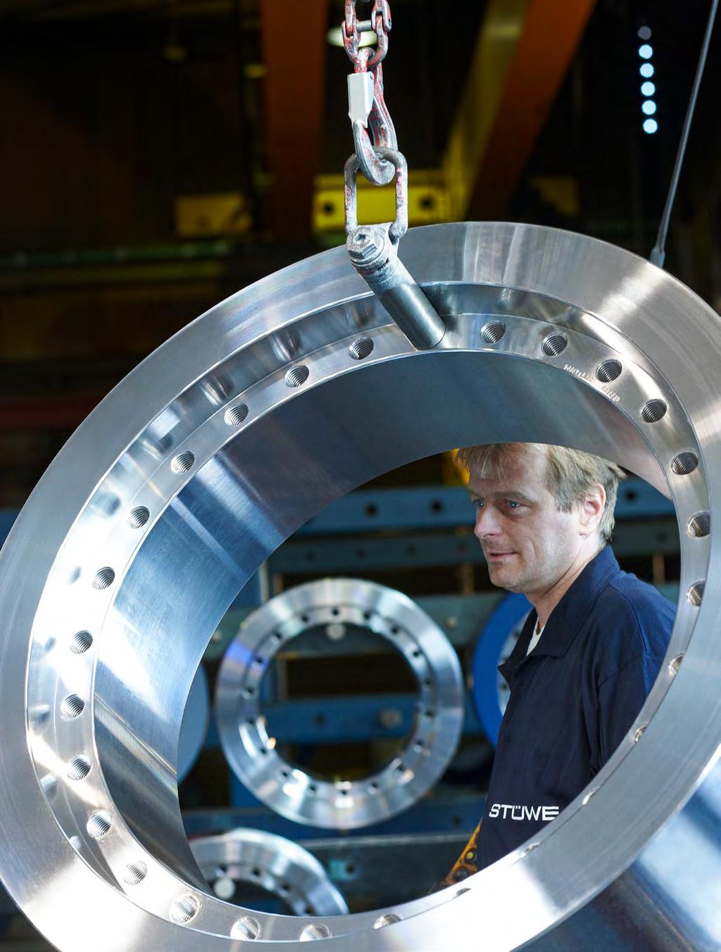
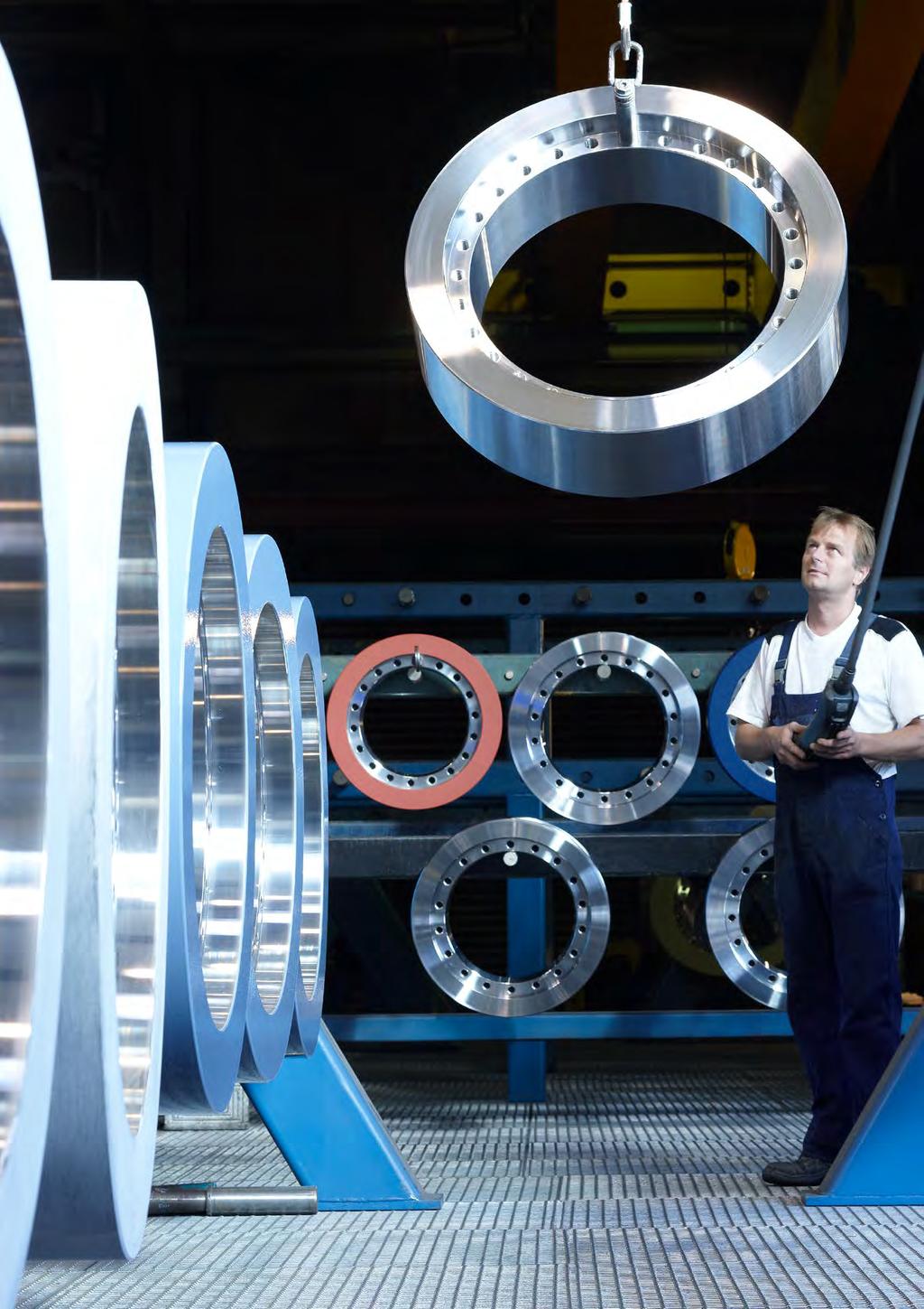
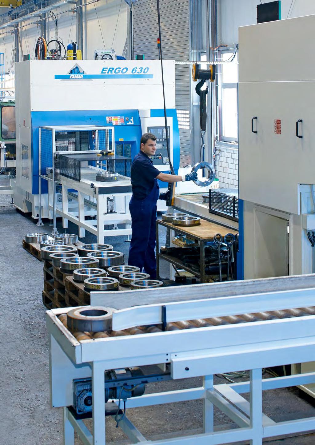
3 Dear business partner, STÜWE GmbH & Co. KG offers the best possible connections in the third generation of ownership. We and our products have stood for skilled work and quality for more than 60 years. In addition to our longstanding supply range which includes shrink discs, locking units, shaft couplings and cardan shaft couplings, we also develop individual customised solutions for any particular application use you may have. Some possible solutions for this can be found here in our catalogue. We are happy at all times to assist you, together with our staff, and to reliably support you in all possible matters. Made in Germany With 60 years of expertise and 120 employees, STÜWE develops highly specialised frictional connections for particularly demanding applications. Since the introduction of its first shrink disc in 1967 STÜWE has been producing exclusively in Germany and has retained its company headquarters in Hattingen. We select our suppliers based on the highest of quality standards and check these regularly through audits. Regular customers have placed their trust in our high standards of skills and quality for many years, in particular for large transmission systems under difficult conditions. As is the case, for example, in wind turbines and ships. Company History Friedhelm Stüwe founded the company Maschinenfabrik STÜWE in 1948 with an original specialisation on the production of cranes and steel products. In 1967 the first shrink disc was launched onto the market. It enables a simple mechanical external join between a shaft and a hub. The ground-breaking technology can even be found as an entry in the technical literature as the STÜWE disc. After the three-piece SD shrink disc, STÜWE also launched the two-piece HSD and hydraulically tensioned connections. Increasing sales and new models require constant extensions to capacity. Rena Stüwe, Jan Stüwe Managing Directors 03

4 A CONNECTION AT A HIGH LEVEL


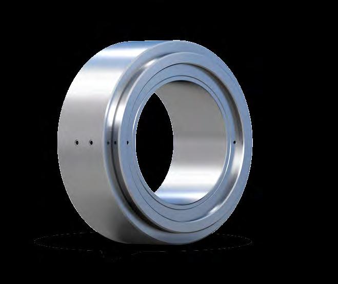
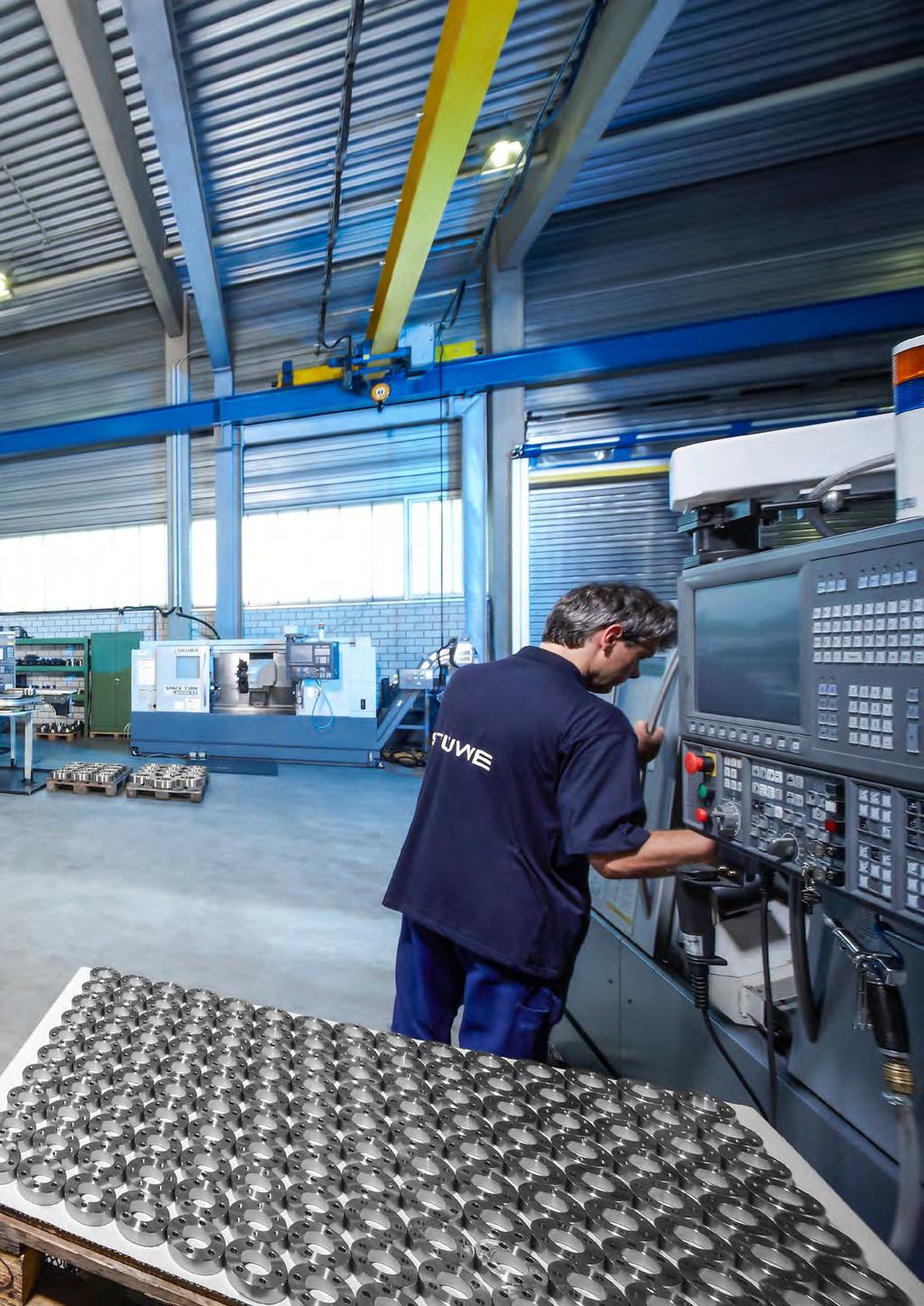
5 High Performance Secure transmission at torques of up to over Suitable for shaft diameters of 8 to over 1000 Quick and easy, space-saving installation and non-destructive removal No fretting corrosion Compact design Normal surface finish qualities of shafts & hubs Can be used as an assembly for a specific application Can be tightened using bolts or hydraulically The Benefits STÜWE frictional connections can be easily and non-destructively installed and removed differently to thermal or friction connections which are joined in other ways. The clearance fit between a shaft and a hub and between a hub and a STÜWE disc enables easy installation and removal. Renowned companies throughout the world appreciate the benefits of our products. Certified Quality Not only our highly qualified employees, but also the latest production technology and the consistent optimisation of operational processes guarantee you the top-class nature of our services. As an ISO 9001 certified company we monitor all steps from the good-inwards inspection of our materials to the final inspection of our precision products. The latest test methods, and not least the great care we take, guarantee you a consistent high level of quality, safety and service life for each individual frictional connection. On request, all STÜWE products may be supplied with acceptance from a classification company. 05
6 CONTENTS


7 General Information p. 07 Product Overview p. 08 Areas of Application p. 10 Technical Specifications p. 11 Shrink Disc TYPE HSD p. 16 General Information p. 17 Technical Charts for Shrink Discs p. 18 Technical Charts for rust-free Shrink Discs p. 36 Shrink Disc TYPE HYD p. 40 General Information p. 41 Technical Charts for Shrink Discs p. 42 Shrink Disc TYPE SDG, SDGH p. 48 General Information p. 49 Technical Charts for Shrink Discs p. 50 External Locking Unit Type AS p. 58 General Information p. 59 Technical Charts for Locking Units p. 61 Shaft Coupling TYPE WK, WKL p. 68 General Information p. 69 Technical Charts for Shaft Couplings p. 70 Flange Coupling TYPE FKH, FKHA, FKHY p. 76 General Information p. 77 Technical Charts for Flange Couplings p. 78 Cardan Shaft Coupling TYPE GF p. 84 General Information p. 85 Technical Charts for Cardan Shaft Couplings p. 86 Internal Locking Unit TYPE IS p. 90 General Information p. 91 Technical Charts for Locking Units p. 92 Examples of Customised Solutions p

8 General Information PRODUCT OVERVIEW Flange Coupling TYPE FKHA p. 76 Locking Unit TYPE AS p. 58 Shaft Coupling TYPE WKL p. 68 Cardan Shaft Coupling TYPE GF p

9 Shrink Disc TYPE HYD p. 40 Shrink Disc TYPE SDG p. 48 Shrink Disc TYPE HSD p. 16 Locking Unit TYPE IS p. 90 Cardan Shaft Coupling TYPE GF p


10 General Information AREAS OF APPLICATION STÜWE frictional connections are versatile in their applications. They can be used in almost all types of drivetrains and in many other applications. The element sizes range from a few to more than 1 000, with transmission torques of a few to more than Wind turbines Wind turbines Shaft-hub connection in wind turbines for the connection of the main shaft and the gearbox Ship Propulsion Systems Shaft coupling in marine powertrains for the connection of the propeller shaft with the main propulsion system Slip-On Gear Units Fastening of levers, gear unit swing arms in such as packaging machines, luggage sorting systems or other handling systems Axial fastening Axial fastening of the bearing inner ring with the aid of a tightening element Cable Railways Fastening of the compensating coupling with the pulley and the drive system Belt Drives Flange coupling for the connection of a geared motor with a drive shaft Further areas of use: Fastening of brake discs Fastening of slip-on gear units to a shaft Fastening of couplings, e.g. in print machines, agitators Axial fastening of mechanical seals Fastening of paddle wheels in tailings facilities Fastening of water wheels Fastening of flywheels Connection of shafts, in such as power looms or other precision mechanical applications 10

 ranges from 0.15 to 0.33.")
11 General Information TECHNICAL SPECIFICATIONS M t = M 2 d P w ax t,liste 2 2 Maximum transmissible torque The transmissible torque and the transmissible axial force is dependent on the coefficient of friction in the press joint which passes on the power, the fit clearance, the clamping length and the shaft diameter. The catalogue value is based on an assumed coefficient of friction, the maximum possible fit clearance and = 0 for a given shaft diameter and a solid shaft. Coefficient of friction The coefficient of friction of dry and grease free surface (steel/steel) ranges from 0.15 to The transmissible torques of the external locking STÜWE discs is calculated using a value of μ w = Greater coefficients of friction may be used for calculation where a particular surface finish is applied. In addition, the surfaces must be thoroughly degreased (by washing with a solvent and additional washing with limewater). Coefficients of friction of about µw = 0.2 may be achieved. The transmissible torque can thus be increased accordingly. Fit clearance The torque calculation takes into account the maximum fit clearance and the surface roughness. If the actual fit between shaft and hub is tighter, then the transmissible torque consequently increases. On the other hand, the transmissible torque decreases if the actual fit is looser than that given in the catalogue. Shaft diameter The shaft diameter range for each frictional connection is specified in the product charts. If a shaft diameter is selected which lies between two given values, the transmissible torque may be found by interpolation to an acceptable level of accuracy. Larger shaft diameters than those given in the charts can be chosen if hub material allows this. The transmissible torque can be found by extrapolation. Axial load The maximum transmissible axial force (for = 0 ) may be calculated using the maximum transmissible torque (for Pax = 0 kn):, max =, Liste Transmission of torque combined with axial load If torsional and axial loads are to be transmitted simultaneously, use the following equation: = 2 d w M 2 t,liste d w 2 is the torque reduced by axial load. 2

12 General Information TECHNICAL SPECIFICATIONS Table 1 Lubricant Source Molykote D 321R (bonded coating) Molykote G Rapid + (paste) Avilub 84 (bonded coating) Dow Corning Dow Corning Avia Banleon Hub material Steel, cast steel or nodular cast iron with a yield strength of at least 360 N/² can be used as hub material. On assemblies which additionally have to transmit bending moments (rotating bending) the hub should be of heat-treated steel like 42CrMo4, higher quality cast steel or nodular cast iron. Grey cast iron can be used for assemblies where negligible bending moments occur. The wall thickness of the hub must in this case be greater than that normally selected. Material All frictional connections are offered in 42CrMo4 as standard. Our products are additionally available in and in It must, however, be noted in these cases that other torques may be transmitted. Depending on the material combinations in each case, a check may be require to be made by our Design Department. Surface quality The surface roughness (Rt) of shaft and hub should be below 16 μm (turning on a lathe is sufficient). Lubricant Conical surfaces are greased with a MoS 2 lubricant (combination of bonded coating and paste). A selection of coercially available lubricants (coefficient of friction µ 0.04) are listed in Table 1. The bolts are lubricated with com- mercially available bolt lubricants (μ=0.1). Tightening bolts All units are equipped with coercial available hexagonal bolts DIN EN ISO 4014/4017, grade 10.9 or More exact specifications may be found in the chart for each type. Alternatively, socket-head cap screws in accordance with DIN EN ISO 4762 may be used or ordered. Additional high-strength washers are used from a tightening bolt size of M16 upwards.
. Maximum stress occurs on the inner diameter.")
13 General Information DESIGN AND CALCULATION M t = M 2 d P w ax t,liste 2 2 HSD p a When tensioning the shrink disc, multidirectional stresses occur in the hub. Tangential and radial stress can be calculated by using the following equation for the thickwalled pipes (axial stress may be ignored). Maximum stress occurs on the inner diameter. p w б rn p w 1+ б t = 1 б r = p w 2 d w d 2 d w d 2 p a б tn tn Resultant stress can be calculated on the basis of the following equation: б v = б t 2 + б r 2 б t б r + 3Г 2 The pressure p w may be determined with the aid of the maximum transmissible torque. p w = 2 d 2 w l μ w 13
14 General Information DESIGN AND CALCULATION M t = M 2 d P w ax t,liste 2 2 IS Hubs are widened by the pressure of the locking units. So that no plastic deformation occurs as a result of the widening, a sufficiently large size for the outside diameter D N of a hub must be selected. The following equation, derived from the equation for thick-walled tubes under internal pressure, can be used to calculate the outside diameter with sufficient accuracy. When using Type IS locking units on hollow shafts, the following formula, which is derived from the equations for thick-walled tubes, may be used for the determination of the maximum permissible hole size d i in a hollow shaft: D N D Whereby σ 0.2N P N C C = 1 σ 0,2N + p N C σ 0,2N - p N C Yield strengths of the hub Pressure in hub bore is a factor based on the width of the hub over the locking unit for hubs which are as wide as the locking unit C = 0.6 for hubs which are twice as wide as the locking unit Regardless of the hub width, the yield strength of the hub material should always be higher than the applied pressure P N. d i d σ 0,2S - 2 p S C σ 0,2S The hole diameter d i can be increased by shrinking in a supporting sleeve. ØD ØDN 14
15 15

16 SHRINK DISC TYPE HSD

17 SHRINK DISC TYPE HSD GENERAL INFORMATION Description of Application The Type HSD shrink disc is a detachable machine element for the connection of a hollow shaft with a shaft. The shrink connection is a maintenance-free connection which is dirt-resistant due to its press fit and which may be used for many different applications. The Type HSD is an inexpensive solution for the connection of a shaft and hub in such as wind turbine drives, packaging machines or luggage sorting systems. Areas of Application Series Shaft diameter Transmissible torque Feature HSD Low torques HSD Medium-sized torques HSD High torques HSD Very high torques HSD Identical to series 22 but % higher torques HSD Identical to series 23 but % higher torques Outer ring* 2 Inner ring* 3 Tightening bolts* including washers where necessary* 4 Hub 5 Shaft *Included in the scope of delivery 17
18 Shrink Disc Type HSD Series 20 H 1 Details of the fit: Ød w : H7/h6 (Ød w <160) H7/g6 (Ød w 160) Ød: H7/f7 Roughness of all fitting surfaces: Ra < 3.2 µm Code Maximum transmissible torque of a shrink disc where =0 Maximum transmissible axial load of shrink disc where =0 ØD ØA Ød l 1.1 x l e Ødw Ød1 Required tightening torque of the tightening bolts (see also Installation and Removal Instructions ) Dimensions H 1 and e apply to untightened units. Shrink Disc Type HSD Series 20 Type d d w kn B* D HSD x M HSD x M HSD x M HSD x M HSD x M HSD x M HSD x M HSD x M HSD x M I H 1 A d 1 e *Tightening bolts: standard DIN EN ISO 4014/4017 Grade 10.9, alternative DIN EN ISO 4762 Grade 10.9 From M16 and larger with washers: DIN EN ISO 7416 When ordering please state: (Type x Ød) e.g. HSD x 34 18
19 Shrink Disc Type HSD Series 20 Type d d w kn B* D HSD x M HSD x M HSD x M HSD x M HSD x M HSD x M HSD x M HSD x M HSD x M HSD x M HSD x M HSD x M HSD x M HSD x M HSD x M HSD x M HSD x M HSD x M I H 1 A d 1 e *Tightening bolts: standard DIN EN ISO 4014/4017 Grade 10.9, alternative DIN EN ISO 4762 Grade 10.9 From M16 and larger with washers: DIN EN ISO 7416 When ordering please state: (Type x Ød) e.g. HSD x
20 Shrink Disc Type HSD Series 20 Type d d w kn B* D HSD x M HSD x M HSD x M HSD x M HSD x M HSD x M HSD x M HSD x M HSD x M I H 1 A d 1 e Further sizes on request. Subject to technical change without notice. *Tightening bolts: standard DIN EN ISO 4014/4017 Grade 10.9, alternative DIN EN ISO 4762 Grade 10.9 From M16 and larger with washers: DIN EN ISO 7416 When ordering please state: (Type x Ød) e.g. HSD x
21 Shrink Disc Type HSD Series 21 H 1 Details of the fit: Ød w : H7/h6 (Ød w <160) H7/g6 (Ød w 160) Ød: H7/f7 Roughness of all fitting surfaces: Ra < 3.2 µm Code Maximum transmissible torque of a shrink disc where =0 Maximum transmissible axial load of shrink disc where Mt =0 ØD ØA Ød l 1,1 x l e Ødw Ød1 Required tightening torque of the tightening bolts (see also Installation and Removal Instructions ) Dimensions H 1 and e apply to untightened units. Shrink Disc Type HSD Series 21 Type d d w kn B* D HSD x M HSD x M HSD x M HSD x M HSD x M HSD x M HSD x M HSD x M HSD x M HSD x M I H 1 A d 1 e *Tightening bolts: standard DIN EN ISO 4014/4017 Grade 10.9, alternative DIN EN ISO 4762 Grade 10.9 From M16 and larger with washers: DIN EN ISO 7416 When ordering please state: (Type x Ød) e.g. HSD x
22 Shrink Disc Type HSD Series 21 Type d d w kn B* D HSD x M HSD x M HSD x M HSD x M HSD x M HSD x M HSD x M HSD x M HSD x M HSD x M HSD x M HSD x M HSD x M HSD x M HSD x M HSD x M HSD x M HSD x M I H 1 A d 1 e Further sizes on request. Subject to technical change without notice. *Tightening bolts: standard DIN EN ISO 4014/4017 Grade 10.9, alternative DIN EN ISO 4762 Grade 10.9 From M16 and larger with washers: DIN EN ISO 7416 When ordering please state: (Type x Ød) e.g. HSD x
23 Shrink Disc Type HSD Series 22 H 1 Details of the fit: Ød w : H7/h6 (Ød w <160) H7/g6 (Ød w 160) Ød: H7/f7 Roughness of all fitting surfaces: Ra < 3.2 µm Code Maximum transmissible torque of a shrink disc where =0 Maximum transmissible axial load of shrink disc where Mt =0 ØD ØA Ød l 1.1 x l e Ødw Ød1 Required tightening torque of the tightening bolts (see also Installation and Removal Instructions ) Dimensions H 1 and e apply to untightened units. Shrink Disc Type HSD Series 22 Type d d w kn B* D HSD x M HSD x M HSD x M HSD x M HSD x M HSD x M HSD x M HSD x M HSD x M I H 1 A d 1 e *Tightening bolts: standard DIN EN ISO 4014/4017 Grade 10.9, alternative DIN EN ISO 4762 Grade 10.9 From M16 and larger with washers: DIN EN ISO 7416 When ordering please state: (Type x Ød) e.g. HSD x 42 23
24 Shrink Disc Type HSD Series 22 Type d d w kn B* D HSD x M HSD x M HSD x M HSD x M HSD x M HSD x M HSD x M HSD x M HSD x M HSD x M HSD x M HSD x M HSD x M HSD x M HSD x M HSD x M HSD x M HSD x M I H 1 A d 1 e *Tightening bolts: standard DIN EN ISO 4014/4017 Grade 10.9, alternative DIN EN ISO 4762 Grade 10.9 From M16 and larger with washers: DIN EN ISO 7416 When ordering please state: (Type x Ød) e.g. HSD x
25 Shrink Disc Type HSD Series 22 Type d d w kn B* D HSD x M HSD x M HSD x M HSD x M HSD x M HSD x M HSD x M HSD x M HSD x M HSD x M HSD x M HSD x M HSD x M HSD x M HSD x M HSD x M HSD x M HSD x M I H 1 A d 1 e *Tightening bolts: standard DIN EN ISO 4014/4017 Grade 10.9, alternative DIN EN ISO 4762 Grade 10.9 From M16 and larger with washers: DIN EN ISO 7416 When ordering please state: (Type x Ød) e.g. HSD x
26 Shrink Disc Type HSD Series 22 Type d d w kn B* D HSD x M HSD x M HSD x M HSD x M HSD x M HSD x M HSD x M HSD x M HSD x M HSD x M HSD x M HSD x M HSD x M I H 1 A d 1 e Further sizes on request. Subject to technical change without notice. *Tightening bolts: standard DIN EN ISO 4014/4017 Grade 10.9, alternative DIN EN ISO 4762 Grade 10.9 From M16 and larger with washers: DIN EN ISO 7416 When ordering please state: (Type x Ød) e.g. HSD x
27 H 1 Shrink Disc Type HSD Series 23 Details of the fit: Ød w : H7/h6 (Ød w <160) H7/g6 (Ød w 160) Ød: H7/f7 Roughness of all fitting surfaces: Ra < 3.2 µm Code Maximum transmissible torque of a shrink disc where =0 Maximum transmissible axial load of shrink disc where Mt =0 ØD ØA Ød l 1.1 x l e Ødw Ød1 Required tightening torque of the tightening bolts (see also Installation and Removal Instructions ) Dimensions H 1 and e apply to untightened units. Shrink Disc Type HSD Series 23 Type d d w kn B* D HSD x M HSD x M HSD x M HSD x M HSD x M HSD x M HSD x M HSD x M HSD x M I H 1 A d 1 e *Tightening bolts: standard DIN EN ISO 4014/4017 Grade 10.9, alternative DIN EN ISO 4762 Grade 10.9 From M16 and larger with washers: DIN EN ISO 7416 When ordering please state: (Type x Ød) e.g. HSD x
28 Shrink Disc Type HSD Series 23 Type d d w kn B* D HSD x M HSD x M HSD x M HSD x M HSD x M HSD x M HSD x M HSD x M HSD x M HSD x M HSD x M HSD x M HSD x M HSD x M HSD x M HSD x M HSD x M HSD x M HSD x M I H 1 A d 1 e Further sizes on request. Subject to technical change without notice. *Tightening bolts: standard DIN EN ISO 4014/4017 Grade 10.9, alternative DIN EN ISO 4762 Grade 10.9 From M16 and larger with washers: DIN EN ISO 7416 When ordering please state: (Type x Ød) e.g. HSD x
29 Shrink Disc Type HSD Series 81 H 1 Details of the fit: Ød w : H7/h6 (Ød w <160) H7/g6 (Ød w 160) Ød: H7/f7 Roughness of all fitting surfaces: Ra < 3.2 µm Code Maximum transmissible torque of a shrink disc where =0 Maximum transmissible axial load of shrink disc where Mt =0 ØD ØA Ød l 1.1 x l e Ødw Ød1 Required tightening torque of the tightening bolts (see also Installation and Removal Instructions ) Dimensions H 1 and e apply to untightened units. Shrink Disc Type HSD Series 81 Type d d w kn B* D HSD x M HSD x M HSD x M HSD x M HSD x M HSD x M HSD x M HSD x M HSD x M HSD x M I H 1 A d 1 e *Tightening bolts: standard DIN EN ISO 4014/4017 Grade 12.9, alternative DIN EN ISO 4762 Grade 12.9 From M16 and larger with washers: DIN EN ISO 7416 When ordering please state: (Type x Ød) e.g. HSD x 60 29
30 Shrink Disc Type HSD Series 81 Type d d w kn B* D HSD x M HSD x M HSD x M HSD x M HSD x M HSD x M HSD x M HSD x M HSD x M HSD x M HSD x M HSD x M HSD x M HSD x M HSD x M HSD x M HSD x M HSD x M HSD x M I H 1 A d 1 e *Tightening bolts: standard DIN EN ISO 4014/4017 Grade 12.9, alternative DIN EN ISO 4762 Grade 12.9 From M16 and larger with washers: DIN EN ISO 7416 When ordering please state: (Type x Ød) e.g. HSD x
31 Shrink Disc Type HSD Series 81 Type d d w kn B* D HSD x M HSD x M HSD x M HSD x M HSD x M HSD x M HSD x M HSD x M HSD x M HSD x M HSD x M HSD x M HSD x M HSD x M I H 1 A d 1 e Further sizes on request. Subject to technical change without notice. *Tightening bolts: standard DIN EN ISO 4014/4017 Grade 12.9, alternative DIN EN ISO 4762 Grade 12.9 From M16 and larger with washers: DIN EN ISO 7416 When ordering please state: (Type x Ød) e.g. HSD x
32 Shrink Disc Type HSD Series 83 H 1 Details of the fit: Ød w : H7/h6 (Ød w <160) H7/g6 (Ød w 160) Ød: H7/f7 Roughness of all fitting surfaces: Ra < 3.2 µm Code Maximum transmissible torque of a shrink disc where =0 Maximum transmissible axial load of shrink disc where Mt =0 ØD ØA Ød l 1.1 x l e Ødw Ød1 Required tightening torque of the tightening bolts (see also Installation and Removal Instructions ) Dimensions H 1 and e apply to untightened units. Shrink Disc Type HSD Series 83 Type d d w kn B* D HSD x M HSD x M HSD x M HSD x M HSD x M HSD x M HSD x M HSD x M HSD x M HSD x M I H 1 A d 1 e *Tightening bolts: standard DIN EN ISO 4014/4017 Grade 12.9, alternative DIN EN ISO 4762 Grade 12.9 From M16 and larger with washers: DIN EN ISO 7416 When ordering please state: (Type x Ød) e.g. HSD x
33 Shrink Disc Type HSD Series 83 Type d d w kn B* D HSD x M HSD x M HSD x M HSD x M HSD x M HSD x M HSD x M HSD x M HSD x M HSD x M HSD x M HSD x M HSD x M HSD x M HSD x M HSD x M HSD x M HSD x M HSD x M HSD x M HSD x M Further sizes on request. Subject to technical change without notice. *Tightening bolts: standard DIN EN ISO 4014/4017 Grade 12.9, alternative DIN EN ISO 4762 Grade 12.9 From M16 and larger with washers: DIN EN ISO 7416, When ordering please state: (Type x Ød) e.g. HSD x 420 I H 1 A d 1 e 33
34 Stainless Steel Shrink Disc Type HSD Series H 1 Details of the fit: Ød w : H7/h6 (Ød w <160) H7/g6 (Ød w 160) Ød: H7/f7 Roughness of all fitting surfaces: Ra < 3.2 µm Code Maximum transmissible torque of a shrink disc where =0 Maximum transmissible axial load of shrink disc where Mt =0 Required tightening torque of the tightening bolts (see also Installation and Removal Instructions ) ØD ØA Ød l 1.1 x l e Ødw Ød1 Dimensions H 1 and e apply to untightened units. µ w The transmissible loads are calculated using a coefficient of friction µ w = 0.1 for stainless steel materials Stainless Steel Shrink Disc Type HSD - Series Type d d w kn B* D HSD x M HSD x M HSD x M HSD x M HSD x M HSD x M HSD x M HSD x M HSD x M I H 1 A d 1 e *Tightening bolts: standard DIN EN ISO 4014/4017 Grade A4-80 From M16 and larger with washers: DIN EN ISO 7416, When ordering please state: (Type x Ød) e.g. HSD x
35 Stainless Steel Shrink Disc Type HSD - Series Type d d w kn B* D HSD x M HSD x M HSD x M HSD x M HSD x M HSD x M HSD x M HSD x M HSD x M HSD x M HSD x M HSD x M HSD x M HSD x M HSD x M HSD x M HSD x M I H 1 A d 1 e *Tightening bolts: standard DIN EN ISO 4014/4017 Grade A4-80 From M16 and larger with washers: DIN EN ISO 7416, When ordering please state: (Type x Ød) e.g. HSD x
36 Stainless Steel Shrink Disc Type HSD - Series Type d d w kn B* D HSD x M HSD x M HSD x M HSD x M HSD x M HSD x M HSD x M HSD x M HSD x M HSD x M I H 1 A d 1 e Further sizes on request. Subject to technical change without notice. *Tightening bolts: standard DIN EN ISO 4014/4017 Grade A4-80 From M16 and larger with washers: DIN EN ISO 7416 When ordering please state: (Type x Ød) e.g. HSD x
37 Stainless Steel Shrink Disc Type HSD Series H 1 Details of the fit: Ød w : H7/h6 (Ød w <160) H7/g6 (Ød w 160) Ød: H7/f7 Roughness of all fitting surfaces: Ra < 3.2 µm Code Maximum transmissible torque of a shrink disc where =0 Maximum transmissible axial load of shrink disc where Mt =0 Required tightening torque of the tightening bolts (see also Installation and Removal Instructions ) ØD ØA Ød l 1.1 x l e Ødw Ød1 Dimensions H 1 and e apply to untightened units. µ w The transmissible loads are calculated using a coefficient of friction µ w = 0.1 for rust-free materials Stainless Steel Shrink Disc Type HSD - Series Type d d w kn B* D HSD x M HSD x M HSD x M HSD x M HSD x M HSD x M HSD x M HSD x M HSD x M I H 1 A d 1 e *Tightening bolts: standard DIN EN ISO 4014/4017 Grade A4-80 From M16 and larger with washers: DIN EN ISO 7416 When ordering please state: (Type x Ød) e.g. HSD x
38 Stainless Steel Shrink Disc Type HSD - Series Type d d w kn B* D HSD x M HSD x M HSD x M HSD x M HSD x M HSD x M HSD x M HSD x M HSD x M HSD x M HSD x M HSD x M HSD x M HSD x M HSD x M HSD x M HSD x M I H 1 A d 1 e *Tightening bolts: standard DIN EN ISO 4014/4017 Grade A4-80 From M16 and larger with washers: DIN EN ISO 7416, When ordering please state: (Type x Ød) e.g. HSD x
39 Stainless Steel Shrink Disc Type HSD - Series Type d d w kn B* D HSD x M HSD x M HSD x M HSD x M HSD x M HSD x M HSD x M HSD x M HSD x M HSD x M I H 1 A d 1 e Further sizes on request. Subject to technical change without notice. *Tightening bolts: standard DIN EN ISO 4014/4017 Grade A4-80 From M16 and larger with washers: DIN EN ISO 7416 When ordering please state: (Type x Ød) e.g. HSD x

40 SHRINK DISC TYPE HYD

41 SHRINK DISC TYPE HYD GENERAL INFORMATION Description of Application The Type HYD hydraulic shrink disc is based on the same principle as the Type HSD mechanical shrink disc. As a result of the hydraulic tensioning, only a fraction of the time for tensioning is required in comparison with the mechanical Type HSD. Areas of Application Series Shaft diameter Transmissible torque HYD HYD Inner ring* 2 Outer ring* 3 Support ring* 4 Safety nut* 5 Hub 6 Shaft *Included in the scope of delivery 41
42 Shrink Disc Type HYD Series 12 H Details of the fit: Ød w : H7/h6 (Ød w <160) H7/g6 (Ød w 160) Ød: H7/f7 Roughness of all fitting surfaces: Ra < 3.2 µm Code Maximum transmissible torque of a shrink disc where =0 Maximum transmissible axial load of shrink disc where Mt =0 l Ødw Ød ØD Shrink Disc Type HYD Series 12 Type d d w kn max. hyd. press bar HYD HYD HYD HYD HYD HYD HYD HYD HYD HYD HYD When ordering please state: (Type x Ød) e.g. HYD x 155 D I H 42
43 Shrink Disc Type HYD Series 12 Type d d w kn Further sizes on request. Subject to technical change without notice. When ordering please state: (Type x Ød) e.g. HYD x 560 max. hyd. press bar HYD HYD HYD HYD HYD HYD HYD HYD HYD HYD HYD HYD HYD HYD HYD HYD HYD HYD D I H 43
44 Shrink Disc Type HYD Series 22 H Details of the fit: Ød w : H7/h6 (Ød w <160) H7/g6 (Ød w 160) Ød: H7/f7 Roughness of all fitting surfaces: Ra < 3.2 µm Code Maximum transmissible torque of a shrink disc where =0 Maximum transmissible axial load of shrink disc where Mt =0 l Ødw Ød ØD Shrink Disc Type HYD Series 22 Type d d w kn max. hyd. press bar HYD HYD HYD HYD HYD HYD HYD HYD HYD HYD HYD When ordering please state: (Type x Ød) e.g. HYD x 150 D I H 44
45 Shrink Disc Type HYD Series 22 Type d d w kn max. hyd. press bar HYD HYD HYD HYD HYD HYD HYD HYD HYD HYD HYD HYD HYD HYD HYD HYD HYD HYD HYD D I H When ordering please state: (Type x Ød) e.g. HYD x
46 Shrink Disc Type HYD Series 22 Type d d w kn max. hyd. press bar HYD HYD HYD HYD HYD HYD HYD HYD D I H Further sizes on request. Subject to technical change without notice. When ordering please state: (Type x Ød) e.g. HYD x
47


48 SHRINK DISC TYPE SDG AND SDGH


49 SHRINK DISC TYPE SDG AND SDGH GENERAL INFORMATION Description of Application The shrink disc Type SDG is a four-piece shrink disc for the space-saving shrinking of disc-shaped components such as gear wheels. A variant of the Type SDG is the two-piece shrink disc Type SDGH. This is frequently used where there is only small fitment space. Areas of Application Series Shaft diameter Transmissible torque Feature SDG 71/ , High torques SDG Highest possible torques Outer ring* 2 Inner ring* 3 Hub (such as a gear-wheel) 4 Shaft 5 Tightening bolts including washers where necessary *Included in the scope of delivery 49
50 Shrink Disc Type SDG Series Roughness of all fitting surfaces: Ra < 3.2 µm H 1 h x Details of the fit: Ød: H7/f7 Ød w : H7/h6 (Ød w <160) H7/g6 (Ød w 160) Code Maximum transmissible torque of a shrink disc where =0 Maximum transmissible axial load of shrink disc where Mt =0 e fx45 Required tightening torque of the tightening bolts (see also Installation and Removal Instructions ) ØD ØA Ød w l/2 Ød Ød 1 Dimensions H 1 and e apply to untightened units. Shrink Disc Type SDG Series Type d d w kn tightening bolts* SDG x M SDG x M SDG x M SDG x M SDG x M SDG x M SDG x M SDG x M D I/2 h H 1 A d 1 e f *Tightening bolts: standard DIN EN ISO 4014/4017 Grade 10.9, alternative DIN EN ISO 4762 Grade 10.9 From M16 and larger with washers: DIN EN ISO 7416 When ordering please state: (Type x Ød) Dimension X, e.g. SDG x 62 X=15 50
51 Shrink Disc Type SDG Series Type d d w kn tightening bolts* SDG x M SDG x M SDG x M SDG x M SDG x M SDG x M SDG x M SDG x M SDG x M SDG x M SDG x M SDG x M SDG x M SDG x M SDG x M SDG x M SDG x M D I/2 h H 1 A d 1 e f *Tightening bolts: standard DIN EN ISO 4014/4017 Grade 10.9, alternative DIN EN ISO 4762 Grade 10.9 From M16 and larger with washers: DIN EN ISO 7416 When ordering please state: (Type x Ød) Dimension X, e.g. SDG x 200 X=40 51
52 Shrink Disc Type SDG Series Type d d w kn tightening bolts* SDG x M SDG x M SDG x M SDG x M SDG x M SDG x M SDG x M SDG x M SDG x M SDG x M D I/2 h H 1 A d 1 e f Further sizes on request. Subject to technical change without notice. *Tightening bolts: standard DIN EN ISO 4014/4017 Grade 10.9, alternative DIN EN ISO 4762 Grade 10.9 From M16 and larger with washers: DIN EN ISO 7416 When ordering please state: (Type x Ød) Dimension X, e.g. SDG x 560 X=110 52
53 Shrink Disc Type SDG Series 91 Roughness of all fitting surfaces: Ra < 3.2 µm H 1 h x Details of the fit: Ød: H7/f7 Ød w : H7/h6 (Ød w <160) H7/g6 (Ød w 160) Code Maximum transmissible torque of a shrink disc where =0 Maximum transmissible axial load of shrink disc where Mt =0 e fx45 Required tightening torque of the tightening bolts (see also Installation and Removal Instructions ) ØD ØA Ød w l/2 Ød Ød 1 Dimensions H 1 and e apply to untightened units. Shrink Disc Type SDG Series 91 Type d d w kn tightening bolts* SDG x M SDG x M SDG x M SDG x M SDG x M SDG x M SDG x M SDG x M SDG x M D I/2 h H 1 A d 1 e f *Tightening bolts: standard DIN EN ISO 4014/4017 Grade 10.9, alternative DIN EN ISO 4762 Grade 10.9 From M16 and larger with washers: DIN EN ISO 7416 When ordering please state: (Type x Ød) Dimension X, e.g. SDG x 260 X=70 53
54 Shrink Disc Type SDG Series 91 Type d d w kn tightening bolts* SDG x M SDG x M SDG x M SDG x M SDG x M SDG x M D I/2 h H 1 A d 1 e f Further sizes on request. Subject to technical change without notice. *Tightening bolts: standard DIN EN ISO 4014/4017 Grade 10.9, alternative DIN EN ISO 4762 Grade 10.9 From M16 and larger with washers: DIN EN ISO 7416 When ordering please state: (Type x Ød) Dimension X, e.g. SDG x 390 X=120 54
55 Shrink Disc Type SDGH Series Roughness of all fitting surfaces: Ra < 3.2 µm H 1 h x Details of the fit: Ød: H7/f7 Ød w : H7/h6 (Ød w <160) H7/g6 (Ød w 160) Code Maximum transmissible torque of a shrink disc where =0 Maximum transmissible axial load of shrink disc where Mt =0 ØD Ød 1 Ød e l fx45 Ød w ØA Required tightening torque of the tightening bolts (see also Installation and Removal Instructions ) all models: X > 1.4 x bolt--ø Model A Dimensions H 1 and e apply to untightened units. Model B Model C Shrink Disc Type SDGH Series Type d d w kn Tightening bolts* SDGH x M SDGH x M SDGH x M SDGH x M SDGH x M SDGH x M D I/2 h H 1 A d 1 e f *Tightening bolts: standard DIN EN ISO 4014/4017 Grade 10.9, alternative DIN EN ISO 4762 Grade 10.9 From M16 and larger with washers: DIN EN ISO 7416 When ordering please state: (Type x Ød x desired model) Dimension X for model C, e.g. SDGH x 50 x C X=10 55
56 Shrink Disc Type SDGH Series Type d d w kn Tightening bolts* SDGH x M SDGH x M SDGH x M SDGH x M SDGH x M SDGH x M SDGH x M SDGH x M SDGH x M SDGH x M SDGH x M SDGH x M SDGH x M SDGH x M SDGH x M SDGH x M D I/2 h H 1 A d 1 e f *Tightening bolts: standard DIN EN ISO 4014/4017 Grade 10.9, alternative DIN EN ISO 4762 Grade 10.9 From M16 and larger with washers: DIN EN ISO 7416 When ordering please state: (Type x Ød x desired model) Dimension X for desired model C, e.g. SDGH x 260 x C X=80 Washers are used for M16 bolts upwards. Dimension X is given by the customer and simply determines the bolt length. 56
57 Shrink Disc Type SDGH Series Type d d w kn Tightening bolts* SDGH x M SDGH x M SDGH x M SDGH x M SDGH x M SDGH x M SDGH x M SDGH x M SDGH x M SDGH x M SDGH x M SDGH x M SDGH x M D I/2 h H 1 A d 1 e f Further sizes on request. Subject to technical change without notice. *Tightening bolts: standard DIN EN ISO 4014/4017 Grade 10.9, alternative DIN EN ISO 4762 Grade 10.9 From M16 and larger with washers: DIN EN ISO 7416 When ordering please state: (Type x Ød x desired model) Dimension X for model C, e.g. SDGH x 560 x C X=115 57


58 EXTERNAL LOCKING UNIT TYPE AS


59 EXTERNAL LOCKING UNIT TYPE AS GENERAL INFORMATION Description of Application External locking units Type AS enable disc-shaped attachments such as brake discs, sheaves or pulleys to be fastened to standard shafts. The fastening of couplings is a further area of use. The external locking unit series 12, 22 and 23 is supplied in the standard delivery prograe in the following designs: Model A: Thread in the outer ring Model AB: Thread in the outer ring and centring Model C: Thread in the attachment Model BC: Thread in the attachment and centring Areas of Application Series Shaft diameter Transmissible torque Feature Medium-sized torques, without bending moment High torques + bending moment Highest possible torques + bending moment Attachment (such as a pulley) 2 Inner ring* 3 Outer ring* 4 Shaft 5 Tightening bolts including washers where necessary *Included in the scope of delivery 59
60 External Locking Unit Type AS Series 12 S h l C ØA Ød w Ød 1 ØD Ød 2 Model A Model AB Model C Model BC Code Maximum transmissible torque of an external locking unit for = 0 Required tightening torque of the tightening bolts (see also Installation and Removal Instructions ) Details of the fit: Ød w : h9 H7/g6 Ød 2: all models: S > 1.4 x Bolts-Ø Roughness of all fitting surfaces: Ra < 3.2 µm For the transmission of torque only. For the transmission of both torque and bending moments select series 22 or
61 External Locking Unit Type AS Series 12 Type d w * B** Grade 10.9 AS x M6 x AS x M6 x AS x M8 x AS x M8 x AS x M8 x AS x M8 x AS x M10 x AS x M12 x AS x M12 x AS x M16 x AS x M16 x AS x M16 x AS x M16 x A D I h C d 1 d 2 Further sizes on request. Subject to technical change without notice. *Diameter d w can be chosen within given limitations. *Tightening bolts: standard DIN EN ISO 4017/4014: Length for model C and BC, alternative DIN EN ISO 4762 From M16 and larger with washers: DIN EN ISO 7416 When ordering please state: (Type x Ød w x desired model) flange width S for model A and AB, e.g. AS x 65 x A S=8 61
62 External Locking Unit Type AS Series 22 S h l C ØA Ød w Ød 1 ØD Ød 2 Model A Model AB Model C Model BC Code Maximum transmissible torque of an external locking unit for = 0 Required tightening torque of the tightening bolts (see also Installation and Removal Instructions ) Details of the fit: Ød w : h9 H7/g6 Ød 2: all models: S > 1.4 x Bolts-Ø Roughness of all fitting surfaces: Ra < 3.2 µm 62
63 External Locking Unit Type AS Series 22 Type d w * B** Grade 10.9 AS x M6 x A D I h C d 1 d 2 AS x M AS x M6 x AS x M6 x AS x M6 x AS x M6 x AS x M6 x AS x M8 x AS x M8 x AS x M8 x AS x M8 x AS x M8 x AS x M8 x AS x M10 x AS x M10 x AS x M12 x AS x M12 x *Diameter d w can be chosen within given limitations. **Tightening bolts: standard DIN EN ISO 4017/4014: Length for model C and BC, alternative DIN EN ISO 4762 From M16 and larger with washers: DIN EN ISO 7416 When ordering please state: (Type x Ød w x desired model) flange width S for model A and AB, e.g. AS x 44 x A S=8 63
64 External Locking Unit Type AS Series 22 Type d w * B** Grade 10.9 AS x M16 x AS x M16 x AS x M16 x AS x M16 x AS x M16 x AS x M20 x AS x M20 x AS x M24 x AS x M24 x AS x M24 x AS x M24 x AS x M24 x AS x M27 x AS x M27 x AS x M27 x AS x M30 x AS x M30 x AS x M30 x A D I h C d 1 d 2 64 Further sizes on request. Subject to technical change without notice. *Diameter d w can be chosen within given limitations. **Tightening bolts: standard DIN EN ISO 4017/4014: Length for model C and BC, alternative DIN EN ISO 4762 From M16 and larger with washers: DIN EN ISO 7416 When ordering please state: (Type x Ød w x desired model) flange width S for model A and AB, e.g. AS x 290 x A S=50
65 External Locking Unit Type AS Series 23 S h l C ØA Ød w Ød 1 ØD Ød 2 Model A Model AB Model C Model BC Code Maximum transmissible torque of an external locking unit for = 0 Required tightening torque of the tightening bolts (see also Installation and Removal Instructions ) Details of the fit: Ød w : h9 H7/g6 Ød 2: all models: S > 1.4 x Bolts-Ø Roughness of all fitting surfaces: Ra < 3.2 µm 65
66 External Locking Unit TYPE AS Series 23 Type d w * B** Grade 10.9 AS x M12 x AS x M12 x AS x M16 x AS x M16 x AS x M16 x AS x M16 x AS x M20 x AS x M20 x AS x M20 x AS x M24 x AS x M24 x AS x M27 x AS x M27 x AS x M27 x AS x M27 x AS x M27 x A D I h C d 1 d 2 *Diameter d w can be chosen within given limitations. **Tightening bolts: standard DIN EN ISO 4017/4014: Length for model C and BC, alternative DIN EN ISO 4762 From M16 and larger with washers: DIN EN ISO 7416 When ordering please state: (Type x Ødw x desired model) flange width S for model A and AB e.g. AS x 175 x A S=50 66
67 External Locking Unit Type AS Series 23 Type d w * B** Grade 10.9 AS x M27 x AS x M27 x AS x M27 x AS x M30 x AS x M30 x AS x M30 x AS x M30 x A D I h C d 1 d 2 Further sizes on request. Subject to technical change without notice. *Diameter d w can be chosen within given limitations. **Tightening bolts: standard DIN EN ISO 4017/4014: Length for model C and BC, alternative DIN EN ISO 4762 From M16 and larger with washers: DIN EN ISO 7416 When ordering please state: (Type x Ødw x desired model) flange width S for model A and AB e.g. AS x 320 x A S=90 67


68 SHAFT COUPLING TYPE WK AND WKL


69 SHAFT COUPLING TYPE WK AND WKL GENERAL INFORMATION Description of Application Shaft couplings Type WK and WKL are suited for those applications where a secure, fixed connection between two free ends of shafts is required with little effort. The couplings are offered for shafts with identical or different shaft diameters. Larger axial distances between the ends of the shafts are dealt with using shaft coupling WKL. Areas of Application Type Shaft diameter Transmissible torque Feature WK The maximum distance between the shaft ends is 0.1 x L. WKL Long design Tightening bolts* including washers where necessary* 2 Outer ring* 3 Inner ring* 4 Shaft 1 5 Shaft 2 *Included in the scope of delivery 69
70 Shaft Coupling Type WK Series 12 h Details of the fit: Ød w : H7/h8 Roughness of all fitting surfaces: Ra < 3.2 µm Code Maximum transmissible torque of a shaft coupling for = 0 Maximum transmissible axial force of a shaft coupling for = 0 ØD ØA Ød w max 0.1 xl L Ød 1 Required tightening torque of the tightening bolts (see also Installation and Removal Instructions ) Shaft Coupling Type WK Series 12 Type d w * kn WK M WK M WK M WK M WK M WK M WK M WK M WK M B** D L h A d 1 *Diameter d w can be chosen within given limitations. **Tightening bolts: standard DIN EN ISO 4017/4014 Grade 10.9, alternative DIN EN ISO 4762 Grade 10.9 From M16 and larger with washers: DIN EN ISO 7416 When ordering please state: (Type x Ød w ), e.g. WK x 43 70
71 Shaft Coupling Type WK Series 12 Type d w * kn WK M WK M WK M WK M WK M WK M WK M WK M WK M WK M WK M WK M WK M WK M WK M WK M WK M Further sizes on request. Subject to technical change without notice. *Diameter d w can be chosen within given limitations. **Tightening bolts: standard DIN EN ISO 4017/4014 Grade 10.9, alternative DIN EN ISO 4762 Grade 10.9 From M16 and larger with washers: DIN EN ISO 7416 When ordering please state: (Type x Ød w ), e.g. WK x 210 B** D L h A d 1 71
72 Shaft Coupling Type WK Series 12 Type d w * kn WK M WK M WK M WK M WK M WK M WK M WK M WK M Further sizes on request. Subject to technical change without notice. *Diameter d w can be chosen within given limitations. **Tightening bolts: standard DIN EN ISO 4017/4014 Grade 10.9, alternative DIN EN ISO 4762 Grade 10.9 From M16 and larger with washers: DIN EN ISO 7416 When ordering please state: (Type x Ød w ), e.g. WK x 710 B** D L h A d 1 72
73 Shaft Coupling Type WKL Series 12 Roughness of all fitting surfaces: Ra < 3.2 µm Details of the fit: Ød w : H7/h8 h ØD ØA Ødw L h Ød1 Model A Model B Code Maximum transmissible torque of a shaft coupling for = 0 Maximum transmissible axial force of a shaft coupling for = 0 Required tightening torque of the tightening bolts (see also Installation and Removal Instructions ) Shaft Coupling WKL Series 12 Type d w * kn WKL M WKL M WKL M WKL M WKL M WKL M *Diameter d w can be chosen within given limitations. **Tightening bolts: standard DIN EN ISO 4017/4014 Grade 10.9, alternative DIN EN ISO 4762 Grade 10.9 From M16 and larger with washers: DIN EN ISO 7416 When ordering please state: (Type x Ød w x desired model), e.g. WKL x 32 x A B** D L h A d 1 73
74 Shaft Coupling Type WKL Series 12 Type d w * kn WKL M WKL M WKL M WKL M WKL M WKL M WKL M WKL M WKL M WKL M WKL M WKL M WKL M WKL M WKL M WKL M WKL M *Diameter d w can be chosen within given limitations. **Tightening bolts: standard DIN EN ISO 4017/4014 Grade 10.9, alternative DIN EN ISO 4762 Grade 10.9 From M16 and larger with washers: DIN EN ISO 7416 When ordering please state: (Type x Ød w x desired model), e.g. WKL x 230 x B B** D L h A d 1 74
75 Shaft Coupling Type WKL Series 12 Type d w * kn WKL M WKL M WKL M WKL M WKL M WKL M WKL M WKL M WKL M WKL M WKL M WKL M Further sizes on request. Subject to technical change without notice. *Diameter d w can be chosen within given limitations. **Tightening bolts: standard DIN EN ISO 4017/4014 Grade 10.9, alternative DIN EN ISO 4762 Grade 10.9 From M16 and larger with washers: DIN EN ISO 7416 When ordering please state: (Type x Ød w x desired model), e.g. WKL x 710 x B B** D L h A d 1 75


76 FLANGE COUPLING TYPE FKH, FKHA, FKHYD


77 FLANGE COUPLINGS TYPE FKH, FKHA, FKHYD GENERAL INFORMATION Description of Application Flange coupling Type FKH and FKHA consists of two halves or a single half-piece and is used to connect shafts with each other through a flange. Flange coupling Type FKHYD is a flange coupling half which is hydraulically tensioned. Through this tensioning method installation time, and thus costs, are reduced. Areas of Application Type Shaft diameter Transmissible torque Feature FKH Complete flange coupling FKHA Half flange coupling FKHYD Transmission of the highest possible torques hydraulic version Tightening bolts* including washers where necessary* 2 Inner ring* 3 Outer ring* 4 Hexagonal nut** 5 Flange* 6 Flange bolt** 7 Shaft *Included in the scope of delivery **Only included in the scope of delivery of Type FKH 77
78 Flange Coupling TYPE FKH f Roughness of all fitting surfaces: Ra < 3.2 µm Details of the fit: Ød w : H7/h6 (Ød w : <160) H7/g6 (Ød w : 160) ØN Øb Ødw L Model A Model B Code Maximum transmissible torque of a flange coupling with = 0 Required tightening torque of the tightening bolts (see also Installation and Removal Instructions ) FL Tightening torque of the flange bolts Flange Coupling TYPE FKH Type d w ** Shrink Disc B*** N b L f Flange bolts* FKH HSD M x M FKH HSD M x M FKH HSD M x M FKH HSD M x M FKH HSD M x M FKH HSD M x M FKH HSD M x M FKH HSD M x M FL *Grade 10.9 **Diameter d w can be chosen within given limitations. ***Tightening bolts for Model A: DIN EN ISO 4014/4017 Grade 10.9, Model B: DIN EN ISO 4762 Grade 10.9 When ordering please state: (Type x Ødw x model), e.g. FKH x 100 x B 78
79 Flange Coupling Type FKH Type d w ** Shrink Disc Further sizes on request. Subject to technical change without notice. *Grade 10.9 **Diameter d w can be chosen within given limitations. ***Tightening bolts for Model A: DIN EN ISO 4014/4017 Grade 10.9, Model B: DIN EN ISO 4762 Grade 10.9 When ordering please state: (Type x Ød w x Model), e.g. FKH x 240 x A B*** N b L f Flange bolts* FKH HSD M x M FKH HSD M x M FKH HSD M x M FKH HSD M x M FKH HSD M x M FKH HSD M x M FKH HSD M x M FKH HSD M x M FKH HSD M x M FKH HSD M x M FL 79
80 Flange Coupling Type FKHA f Roughness of all fitting surfaces: Ra < 3.2 µm Details of the fit: Ød w : H7/h6 (Ød w : <160) H7/g6 (Ød w : 160) Øc: h6 t ØN Øb Ødw L Øc Model A - external spigot location Model A - internal spigot location Model B - external spigot location Model B - internal spigot location Code Maximum transmissible torque of a flange coupling with = 0 Required tightening torque of the tightening bolts (see also Installation and Removal Instructions ) FL Tightening torque of the flange bolts Dimensions N, b, c, t plus quantity and size of flange bolts depend on the counter-flange and can be changed if necessary. Please give the desired dimensions where these differ from the values in the chart. Flange Coupling FKHA Type d w ** Shrink Disc B*** N *Grade 10.9 **Diameter d w can be chosen within given limitations. ***Tightening bolts for Model A: DIN EN ISO 4014/4017 Grade 10.9, Model B: DIN EN ISO 4762 Grade 10.9 When ordering please state: (Type x Ød w x model), e.g. FKHA x 135 x B, where necessary dimensions N, b, c, t, number & size of the flange bolts b c L f t Flange bolts* FKHA HSD M x M FKHA HSD M x M FKHA HSD M x M FKHA HSD M x M FKHA HSD M x M FKHA HSD M x M FL 80
81 Flange Coupling Type FKHA Type d w ** Shrink Disc B*** Further sizes on request. Subject to technical change without notice. *Grade 10.9 **Diameter d w can be chosen within given limitations. ***Tightening bolts for Model A: DIN EN ISO 4014/4017 Grade 10.9, Model B: DIN EN ISO 4762 Grade 10.9 When ordering please state: (Type x Ød w x model), e.g. FKHA x 225 x A, where necessary dimensions N, b, c, t, number & size of the flange bolts N b c L f t Flange bolts* FKHA HSD M x M FKHA HSD M x M FKHA HSD M x M FKHA HSD M x M FKHA HSD M x M FKHA HSD M x M FKHA HSD M x M FKHA HSD M x M FL 81
82 Flange Coupling Type FKHYD f Details of the fit: Ød w : H7/h6 (Ød w : <160) H7/g6 (Ød w : 160) Øc: h6 t Roughness of all fitting surfaces: Ra < 3.2 µm ØD Ødw l L Øc Øb ØN Code Maximum transmissible torque of a flange coupling with = 0 max. hyd. Press Maximum hydraulic pressure Dimensions N, b, c, t plus quantity and size of flange bolts depend on the counter-flange. These data must therefore be also given when ordering. Flanges can also be supplied with an internal spigot location. Flange Coupling FKHYD Type d w * max. hyd. press bar FKHYD FKHYD FKHYD FKHYD FKHYD FKHYD FKHYD *Diameter d w can be chosen within given limitations. When ordering please state: (Type x Ø dw), e.g. FKHYD x 155, dimensions N, b, c, t, number & size of the flange bolts N D L I f 82
83 Flange Coupling FKHYD Type d w * max. hyd. press bar FKHYD FKHYD FKHYD FKHYD Further sizes on request. Subject to technical change without notice. *Diameter d w can be chosen within given limitations. When ordering please state: (Type x Ø dw), e.g. FKHYD x 360, dimensions N, b, c, t, number & size of the flange bolts N D L I f 83


84 CARDAN SHAFT COUPLING TYPE GF

85 CARDAN SHAFT COUPLING TYPE GF GENERAL INFORMATION Description of Application Cardan shaft flange Type GF is suited for the connection of standard cardan shafts. The following characteristics distinguish the flanges: Perfect power transmission, quick and easy installation, secure connection of cardan shafts with varying shaft ends. Series 21 Series 22 Series 23 Cardan Shaft Cardan Shaft Cardan Shaft Cardan Shaft Cardan Shaft Cardan Shaft Model A Model B Model A Model B Areas of Application Model A Model B Series Shaft diameter Transmissible torque Feature Flange bolts are also used for tensioning Primarily for the connection of small shaft diameters with large cardan shaft flanges Primarily for the connection of large shaft diameters Shaft 2 Outer ring* 3 Inner ring* 4 Tightening bolts* including washers where necessary* 5 Cardan Shaft 6 Flange bolts *Included in the scope of delivery
86 Cardan Shaft Coupling Type GF Series 21 L Details of the fit: Ød w : H7/h8 Øc: H7/e6 Model A Roughness of all fitting surfaces: Ra < 3.2 µm l Z ØD Ødw Øc Øb Øa t R Model B Z Dimension L apply to untightened units. Details of the corner radius R GF to GF-75-21: R0.4 GF to GF : R0.8 Code Maximum transmissible torque of a cardan shaft coupling where = 0 Maximum transmissible axial load of cardan shaft coupling where =0 Required tightening torque of the tightening bolts (see also Installation and Removal Instructions ) Cardan Shaft Coupling Type GF Series 21 Type d w * * D I L a b c t Flange bolts** GF x M GF x M GF x M GF x M GF x M GF x M GF x M Further sizes on request. Subject to technical change without notice. *Diameter d w can be chosen within given limitations. **Grade 12.9 Connection dimensions may be adjusted on request. Model B: From M16 and larger with washers: DIN EN ISO 7416 When ordering please state: (Type x Ød w x model), e.g. B. GF x 60 x A Additional: flange holes, bolt size and bolt quantity if different from the catalogue values
87 Cardan Shaft Coupling Type GF Series 22 L Details of the fit: Ød w : H7/h8 Øc: H7/e6 Model A Z Roughness of all fitting surfaces: Ra < 3.2 µm l ØD Ødw Øc Øb Øa t R0,8 Model B Z Dimension L apply to untightened units. Code Maximum transmissible torque of a cardan shaft coupling where = 0 Maximum transmissible axial load of cardan shaft coupling where Mt =0 Required tightening torque of the tightening bolts (see also Installation and Removal Instructions ) Cardan Shaft Coupling Type GF Series 22 Type d w * * Tightening bolts size D I L a b c t Flange bolts** GF M x M GF M x M GF M x M GF M x M GF M x M GF M x M GF M x M GF M x M Further sizes on request. Subject to technical change without notice. *Diameter d w can be chosen within given limitations. **Grade 10.9 Connection dimensions may be adjusted on request. Model A: From M16 and larger with washers: DIN EN ISO 7416 When ordering please state: (Type x Ød w x model), e.g. B. GF x 100 x A Additional: flange holes, bolt size and bolt quantity if different from the catalogue values 87
88 Cardan Shaft Coupling Type GF Series 23 L Details of the fit: Ød w : H7/h8 Øc: H7/e6 Roughness of all fitting surfaces: Ra < 3.2 µm Dimension L apply to untightened units. l Z ØD Ødw Øc Øb Øa t Model A R0,8 Z Model B Code Maximum transmissible torque of a cardan shaft coupling where = 0 Maximum transmissible axial load of cardan shaft coupling where Mt =0 Required tightening torque of the tightening bolts (see also Installation and Removal Instructions ) 88
89 Cardan Shaft Coupling Type GF Series 23 Type d w * Tightening bolts size D I L a b c t Flange bolts** GF M x M GF M x M GF M x M GF M x M GF M x M GF M x M GF M x M GF M x M Further sizes on request. Subject to technical change without notice. *Diameter d w can be chosen within given limitations. **Grade 10.9 Connection dimensions may be adjusted on request. Model A: From M16 and larger with washers: DIN EN ISO 7416 When ordering please state: (Type x Ød w x model), e.g. B. GF x 150 x A Additional: flange holes, bolt size and bolt quantity if different from the catalogue values 89

90 INTERNAL LOCKING UNIT TYPE IS


91 INTERNAL LOCKING UNIT TYPE IS GENERAL INFORMATION Description of Application Hubs of all kinds can be fastened to coercially available shafts using internal locking units. Within this range, each type provides the following benefits: self-centring, self-locking taper angles, increase in concentricity through pre-centring Areas of Application Series Shaft diameter Transmissible torque Feature IS Small space for fitment Movement of the hub when tightening ISN IS IS Axial fixing No movement of the hub when tightening For the highest possible torques No movement of the hub when tightening Reduced contact pressure Especially suited for conveyor belt drums No movement of the hub when tightening Outer ring 1* 2 Inner ring 1* 3 Shaft 4 Inner ring 2* 5 Outer ring 2* 6 Tightening bolts* 7 Hub (for example, of a gearwheel) *Included in the scope of delivery 91
92 Internal Locking Unit Type IS Series IS 1 L 4 L 2 Details of the fit: Ød: h8 ØD: H8 Roughness of all fitting surfaces: Ra < 3.2 µm Code Maximum transmissible torque of a locking unit where = 0 Maximum transmissible axial load of a locking unit where =0 Required tightening torque of the tightening bolts L 1 P w Contact pressure between locking unit and shaft Ød L 3 ØD P n Contact pressure between locking unit and hub Dimensions L 3 and L 4 apply to untightened units. Internal Locking Unit Type IS Series IS 1 Type d x D kn L 1 L 2 L 3 L 4 B* Grade 12.9 P w N/² IS1 20 x x M IS1 22 x x M IS1 24 x x M IS1 25 x x M IS1 28 x x M IS1 30 x x M IS1 35 x x M IS1 40 x x M IS1 45 x x M IS1 50 x x M IS1 55 x x M IS1 60 x x M IS1 65 x x M IS1 70 x x M IS1 75 x x M IS1 80 x x M IS1 85 x x M IS1 90 x x M IS1 95 x x M IS1 100 x x M IS1 110 x x M *Tightening bolts DIN EN ISO 4762: Grade 12.9 When ordering please state: (Type x Ød x ØD) e.g. IS x 145 P n 92
93 Internal Locking Unit Type IS Series IS 1 Type d x D kn L 1 L 2 L 3 L 4 B* Grade 12.9 P w N/² IS1 120 x x M IS1 130 x x M IS1 140 x x M IS1 150 x x M IS1 160 x x M IS1 170 x x M IS1 180 x x M IS1 190 x x M IS1 200 x x M IS1 220 x x M IS1 240 x x M IS1 260 x x M IS1 280 x x M IS1 300 x x M IS1 320 x x M IS1 340 x x M IS1 360 x x M IS1 380 x x M IS1 400 x x M IS1 420 x x M IS1 440 x x M IS1 460 x x M IS1 480 x x M IS1 500 x x M P n Further sizes on request. Subject to technical change without notice. *Tightening bolts DIN EN ISO 4762: Grade 12.9 When ordering please state: (Type x Ød x ØD) e.g. IS x
94 Internal Locking Unit Type IS Series ISN 1 L 5 L 4 L 2 Details of the fit: Ød: h8 ØD: H8 Roughness of all fitting surfaces: Ra < 3.2 µm Code Maximum transmissible torque of a locking unit where = 0 Maximum transmissible axial load of a locking unit where =0 Required tightening torque of the tightening bolts L 1 P w Contact pressure between locking unit and shaft ØD+9 Ød L 3 ØD P n Contact pressure between locking unit and hub Dimensions L 3 and L 4 apply to untightened units. Internal Locking Unit IS Series ISN 1 Type d x D kn L 1 L 2 L 3 L 4 L 5 *Tightening bolts DIN EN ISO 4762: Grade 12.9 When ordering please state: (Type x Ød x ØD) e.g. ISN x 155 B* Grade 12.9 P w N/² ISN 1 20 x x M ISN 1 22 x x M ISN 1 24 x x M ISN 1 25 x x M ISN 1 28 x x M ISN 1 30 x x M ISN 1 35 x x M ISN 1 40 x x M ISN 1 45 x x M ISN 1 50 x x M ISN 1 55 x x M ISN 1 60 x x M ISN 1 65 x x M ISN 1 70 x x M ISN 1 75 x x M ISN 1 80 x x M ISN 1 85 x x M ISN 1 90 x x M ISN 1 95 x x M ISN x x M ISN x x M P n 94
95 Internal Locking Unit Type IS Series ISN 1 Type d x D kn L 1 L 2 L 3 L 4 L 5 B* Grade 12.9 P w N/² ISN x x M ISN x x M ISN x x M ISN x x M ISN x x M ISN x x M ISN x x M ISN x x M ISN x x M ISN x x M ISN x x M ISN x x M ISN x x M ISN x x M ISN x x M ISN x x M ISN x x M ISN x x M ISN x x M ISN x x M ISN x x M ISN x x M ISN x x M ISN x x M P n Further sizes on request. Subject to technical change without notice. *Tightening bolts DIN EN ISO 4762: Grade 12.9 When ordering please state: (Type x Ød x ØD) e.g. ISN x
96 Internal Locking Unit Type IS Series IS 4 L 4 L 2 Details of the fit: Ød: h8 ØD: H8 Roughness of all fitting surfaces: Ra < 3.2 µm Code Maximum transmissible torque of a locking unit where = 0 Maximum transmissible axial load of a locking unit where =0 Required tightening torque of the tightening bolts P w Contact pressure between locking unit and shaft Ød L 1 L 3 ØD P n Contact pressure between locking unit and hub Dimensions L 3 and L 4 apply to untightened units. Internal Locking Unit IS Series IS 4 Type d x D kn L 1 L 2 L 3 L 4 B* Grade 12.9 P w N/² IS 4 30 x x M IS 4 35 x x M IS 4 40 x x M IS 4 45 x x M IS 4 50 x x M IS 4 55 x x M IS 4 60 x x M IS 4 65 x x M IS 4 70 x x M IS 4 75 x x M IS 4 80 x x M IS 4 85 x x M IS 4 90 x x M IS 4 95 x x M IS x x M IS x x M IS x x M IS x x M IS x x M IS x x M IS x x M *Tightening bolts DIN EN ISO 4762: Grade 12.9 When ordering please state: (Type x Ød x ØD) e.g. IS 4 x 100 x 145 P n 96
97 Internal Locking Unit Type IS Series IS 4 Type d x D kn L 1 L 2 L 3 L 4 Further sizes on request. Subject to technical change without notice. *Tightening bolts DIN EN ISO 4762: Grade 12.9 When ordering please state: (Type x Ød x ØD) e.g. IS x 260 B* Grade 12.9 P w N/² IS x x M IS x x M IS x x M IS x x M IS x x M IS x x M IS x x M IS x x M IS x x M IS x x M IS x x M IS x x M IS x x M IS x x M IS x x M IS x x M IS x x M IS x x M IS x x M IS x x M IS x x M IS x x M IS x x M IS x x M P n 97
98 Internal Locking Unit Type IS Series IS 4.1 L 4 L 2 Details of the fit: Ød: h8 ØD: H8 Roughness of all fitting surfaces: Ra < 3.2 µm Code Maximum transmissible torque of a locking unit where = 0 Maximum transmissible axial load of a locking unit where =0 Required tightening torque of the tightening bolts P w Contact pressure between locking unit and shaft Ød L 1 L 3 ØD P n Contact pressure between locking unit and hub Dimensions L 3 and L 4 apply to untightened units. Internal Locking Unit IS Series IS 4.1 Type d x D kn L 1 L 2 L 3 L 4 B* Grade 12.9 P w N/² IS x x M IS x x M IS x x M IS x x M IS x x M IS x x M IS x x M IS x x M IS x x M IS x x M IS x x M IS x x M IS x x M IS x x M IS x x M IS x x M IS x x M IS x x M IS x x M IS x x M IS x x M P n *Tightening bolts DIN EN ISO 4762: Grade 12.9 When ordering please state: (Type x Ød x ØD) e.g. IS x
99 Internal Locking Unit IS Series IS 4.1 Type d x D kn L 1 L 2 L 3 L 4 Further sizes on request. Subject to technical change without notice. *Tightening bolts DIN EN ISO 4762: Grade 12.9 When ordering please state: (Type x Ød x ØD) e.g. IS x 515 B* Grade 12.9 P w N/² IS x x M IS x x M IS x x M IS x x M IS x x M IS x x M IS x x M IS x x M IS x x M IS x x M P n 99

100 CUSTOMISED SOLUTIONS
101 CUSTOMISED SOLUTIONS EXAMPLES Description of Application We offer an extensive selection of customised solutions in addition to our standard delivery program. Solving tasks with Customised Versions With around 50 years of expertise, STÜWE is today still among the world s leading manufacturers and a leader in technology in the field of frictional connections. With our highly modern design methods we ensure that our standard solutions are consistently developed and design customised solutions which are tailored to solve your problem area. This means that, should the perfect solution to your individual application be unable to be found within our extensive product range of frictional connections, both our specialist engineers and our representatives will be pleased to help you at all times. Our experienced design team will skilfully and efficiently implement your technical and financial demands while taking into account quality characteristics und any possible requirements from certifying authorities. Through our great depth of in-house manufacture, our extensive machinery and our extensive network of suppliers we are able to react rapidly and flexibly to your enquiries. Through the examples shown on the following pages you can gain an impression of our possibilites. 101

 5 Shaft *Included in the scope of delivery Complete")


102 Example: Internal locking frictional connection Individual Solution UHSD Benefits Lower fitment space Greater design freedom 1 Inner ring* 2 Outer ring* 3 Tightening bolts* including washers where necessary* 4 Hub (such as a gear-wheel) 5 Shaft *Included in the scope of delivery Complete Solution ZSDG Example: Complete gearwheel including tightening elements Benefits 4 Less components Delivery of a finished component 1 Outer ring* 2 Tightening bolts* including washers where necessary* 3 Gearwheel with Integrated inner ring* 4 Outer ring* *Included in the scope of delivery 102


103 Combination Solution HSD + AS Example: Combination of a shrink disc and an external locking unit Benefits Less components Lower costs 1 Tightening bolts including washers where necessary 2 Outer ring* 3 Inner ring* 4 Hub 5 Shaft *Included in the scope of delivery HSD with an integrated spacer Integration of partial solutions into the connecting element Benefits Less components Quick and easy installation 1 Tightening bolts* including washers where necessary* 2 positioning component (such as a bearing) 3 Outer ring* 4 Inner ring with an integrated Spacer sleeve* 5 Hub 6 Shaft *Included in the scope of delivery 103


104 Connecting element and seal Dual Function HSD with Grooves Benefits Less components Easy handling 1 Inner ring* 2 Outer ring* 3 Hollow shaft 4 Shaft 5 Tightening bolts* including washers where necessary* *Included in the scope of delivery SD with Protection Benefit No radial access to the bolt heads Outer ring* 2 Tightening bolts* including washers where necessary* 3 Inner ring* 4 Hollow shaft 5 Shaft *Included in the scope of delivery 104
105
FRICTIONAL CONNECTIONS CATALOGUE
 FRICTIONAL CONNECTIONS CATALOGUE Reprinting and all other forms of copying, not even partially, is prohibited without permission from Stüwe. Maschinenfabrik GmbH & Co. KG Production: Studio Salewski GmbH,
Shaft-Hub-Connections
 Stand: 14.01.2010 Shaft-Hub-Connections Shrink Discs Cone Clamping Elements Star Discs 36 Edition 2012/2013 RINGSPANN Eingetragenes Warenzeichen der RINGSPANN GmbH, Bad Homburg Table of Contents Introduction
Shrink Discs, Smart-Lock & Shaft Couplings
 RINGFEDER Products are available from MARYLAND METRICS Shrink Discs, Smart-Lock & Shaft Couplings US 08 2009 Partner for performance RINGFEDER Products are available from MARYLAND METRICS P.O. Box 261
For advanced drive technology CLAMPEX. Shaft-Hub-Connection. KTR Precision Joints CLAMPEX
 technology CLAMPEX Shaft-Hub-Connection CLAMPEX KTR Precision Joints 07 technology Table of contents Page Brief information 09 Selection and calculation -5 CLAMPEX -Selection Shaft diameter = d 0 10 0
In-house development Own manufacturing Sole distributor in Germany Working with distributors worldwide
 In-house development Own manufacturing Sole distributor in Germany Working with distributors worldwide External Clamping devices Overview 3073 Mini-Range For very low torque transmission Very small profile
For advanced drive technology CLAMPEX. Shaft-hub-connection. KTR Precision joints CLAMPEX
 technology CLAMPEX Shaft-hub-connection CLAMPEX KTR Precision joints 227 technology Table of contents Page Brief information 228 Selection and calculation 25-255 CLAMPEX -Selection Shaft diameter = d 0
Locking Assemblies Shrink Discs Rigid Couplings.
 M I N I Locking Assemblies Shrink Discs Rigid Couplings www.mav.it our company We are an Italian company world renowned for our creativity and ethics. Established in 1989 we have rapidly built a reputation
Shaft Couplings Flange-Couplings Rigid Shaft Couplings Flexible Couplings
 Shaft Couplings Flange-Couplings Rigid Shaft Couplings Flexible Couplings 44 Edition 2013/2014 RINGSPANN Registered Trademark of RINGSPANN GmbH, Bad Homburg 2 Table of Contents Flange-Couplings Page Flange-Couplings
In-house development Own manufacturing Sole distributor in Germany Working with distributors worldwide
 In-house development Own manufacturing Sole distributor in Germany Working with distributors worldwide External Clamping devices Overview 3173 Mini-Range For very low torque transmission Very small profile
NEW. Cone Clamping Elements Trantorque Keyless Locking Devices for very small diameters from 3 mm. E03.050e
 Cone Clamping Elements Trantorque Keyless Locking Devices for very small diameters from 3 mm NEW E03.050e Backlash free positioning Excellent concentricity Quick mounting by central clamping nut Issue
Locking Assemblies & Locking Elements
 US 01 2016 Locking Assemblies & Locking Elements Partner for Performance www.ringfeder.com Welcome to your system supplier for every aspect of power transmission Today s RINGFEDER POWER TRANSMISSION GMBH
CONTENT. 1. Syllabus 2. Introduction 3. Shaft 4. Coupling. Rigid coupling. Flange coupling. Sleeve (or) muff coupling Split muff coupling
 muff coupling Split muff coupling") UNIT II 1. Syllabus 2. Introduction 3. Shaft 4. Coupling Rigid coupling CONTENT Flange coupling Protected flange coupling Unprotected flange coupling Marine type flange coupling Sleeve (or) muff coupling
UNIT II 1. Syllabus 2. Introduction 3. Shaft 4. Coupling Rigid coupling CONTENT Flange coupling Protected flange coupling Unprotected flange coupling Marine type flange coupling Sleeve (or) muff coupling
SIT-LOCK self locking elements
 self locking elements Advantages of on the shaft-hub connection compared with traditional systems Easy assembly and disassembly Both actions take place by locking and unlocking the clamping screws with
Solutions for power transmission. MAV-standardisarja.
 Solutions for power transmission MAV-standardisarja www.konaflex.fi L O C K I N G A S S E M B L I E S Shrink disc Mini Series Rigid Couplings www.mav.it our company We are an Italian company world renowned
hydraulic actuated products EP: EP:
 In-house development Own manufacturing Sole distributor in Germany Working with distributors worldwide hydraulic actuated products EP: 0 812 397 EP: 1 666 748 Overview Hydraulic shrink disc SHS Standard
Locking Assemblies & Locking Elements
 US 12 2010 Locking Assemblies & Locking Elements Partner for performance www.ringfeder.com A Global Presence For You The RINGFEDER POWER TRANSMISSION GMBH was founded in 1922 in Krefeld, Germany to fabricate
RINGFEDER KEYLESS SHAFT/HUB CONNECTIONS LOCKING ASSEMBLIES TM LOCKING ELEMENTS TM SHRINK DISCS W-300-2
 RINGFEDER KEYLESS SHAFT/HUB CONNECTIONS LOCKING ASSEMBLIES TM LOCKING ELEMENTS TM SHRINK DISCS W-300-2 1 Ringfeder Corporation Catalog W-300-1 Shaft-Hub Locking Devices Ringfeder unique frictional, keyless
SCHMIDT-KUPPLUNG GmbH
 Loewe GK About us Many years of experience For 50 years, we have been advising machine manufacturers as partners for compact coupling systems. Our experience in power transmission has given us extensive
RINGFEDER Shrink Discs RfN 4091
 RINGFEDER Shrink Discs RfN 4091 Heavy Duty Series Shrink Disc RINGFEDER RfN 4091 Location Shrink Disc RINGFEDER RfN 4091 Dimensions Lever metric example 40 Size Shrink Disc dimensions Transmissible torques
Shaft Couplings Tru-Line Flange-Couplings Rigid Shaft Couplings Flexible Couplings
 Shaft Couplings Tru-Line Flange-Couplings Rigid Shaft Couplings Flexible Couplings Edition 2015/2016 RINGSPANN Registered Trademark of RINGSPANN GmbH, Bad Homburg Table of Contents Tru-Line Flange-Couplings
RINGFEDER Shrink Discs RfN 4073
 RINGFEDER Shrink Discs RfN 4073 Ultra Light Duty Series Shrink Disc RINGFEDER RfN 4073 Location Shrink Disc RINGFEDER Dimensions Worm gear (metric example) 36 Size Shrink Disc dimensions Transmissible
TRADITIONAL SHAFT HUB CONNECTIONS
 TABLE OF CONTENTS MAV locking devices.... Pg. 2 Traditional shaft hub connections...pg. 3 Advantages of MAV locking devices...pg. 4 The wedge principle..... Pg. 5 Installation removal...pg. 6 Characteristics....
TECHNICAL INFORMATION
 General Nomenclature Spherical Roller Bearings The spherical roller bearing is a combination radial and thrust bearing designed for taking misalignment under load When loads are heavy, alignment of housings
RFC SPECIALTY LOCKING DEVICES
 RINGFEDER Products are available from MARYLAND METRICS P.O. Box 261 Owings Mills, MD 21117 USA email: sales@mdmetric.com web: http://mdmetric.com phones: (410)358-3130 (800)638-1830 faxes: (410)358-3142
Zertifiziert. nach DIN-EN-ISO Shaft Couplings
 Zertifiziert nach DIN-EN-ISO 9001 Shaft Couplings SHAFT COUPLINGS Ensuring an absolutely rigid connection of shafts and high accuracy of alignment Dimensions Applications Installation Tolerances: Shaft
Rexnord Tollok Locking Assemblies
 Tollok Catalog Download the most up-to-date version at www.rexnord.com/documentation Rexnord Tollok Locking Assemblies Why Choose Rexnord Tollok Locking Assemblies? Why Choose Rexnord? When it comes to
RINGFEDER Locking Assemblies. Catalogue. RfN For high torques & axial loads
 RINGFEDER Locking Assemblies GB 03 04 Catalogue RfN 7014 For high torques & axial loads RINGFEDER Locking Assemblies RfN 7014 Please note that our guarantee refers to our products only. Because of the
TRANSMISSIONS. Mechanical Power Transmission
 TRANSMISSIONS Mechanical Power Transmission Dunlop BTL Ltd European Distribution Centre MPT House Brunswick Road Cobbs Wood Industrial Estate Ashford, Kent. UK TN23 1EL Contact us +44 (0)1233 663340 +44
Selection Tool. on the Internet at in the section MÄDLER -Tools. Other sizes and designs on request. Connecting Shafts Page 766
 Couplings Overview Friction Clutches Friction Clutches Type B Axial Arrangement Friction Clutches Type C Transversal Flexibility Sliding Hubs with Torsionally-Flexible Coupling Multi-Disk Friction Clutches
DESIGN OF MACHINE MEMBERS - I
 R10 Set No: 1 III B.Tech. I Semester Regular and Supplementary Examinations, December - 2013 DESIGN OF MACHINE MEMBERS - I (Mechanical Engineering) Time: 3 Hours Max Marks: 75 Answer any FIVE Questions
Power-Lock shaft-hub locking devices provide simple and highly secure connections.
 POWER-LOCK Power-Lock shaft-hub locking devices provide simple and highly secure connections. AS Series Multipurpose locking devices available in stainless steel and electroless nickelplated finish, in
DYNA GEAR. The highly dynamic servo right angle gearbox.
 MS- Gr a es s ne r GmbH & Co. K G THE GEAR COM PAN Y The highly dynamic servo right angle gearbox Internal highlights The design of the DynaGear range has been influenced by extremely varied applications
Z-LOCK INDEX Z2 Z5 Z5/Z6 ZSD ZSD Z-LOCK
 Z-LOCK INDEX TOPIC PAGE INTRODUCTION 1 TYPICAL APPLICATION 2 Z2 MEDIUM DUTY, NON SELF CENTERING 3-4 Z2 MINIMUM HUB DIAMETERS 5 Z2 FITTING INSTRUCTIONS 6 Z5 HEAVY DUTY, SELF CENTERING 7 Z5 MINIMUM HUB DIAMETERS
Guide units. For toolmaking, fixture manufacturing and machine engineering
 Guide units For toolmaking, fixture manufacturing and machine engineering Guide units in compliance with DIN, ISO and STEINEL standards or according to your specifications Guide pillars Guide and pillar
RE / STAR Tolerance Rings STAR Ball Knobs, Knob and Lever Type Handles
 RE 2 970/.99 STAR Tolerance Rings STAR Ball Knobs, Knob and Lever Type Handles STAR Tolerance Rings Product Overview Tolerance rings are made of hard, embossed spring steel strip and belong to the class
HT hypoid bevel gear boxes
 HT hypoid bevel gear boxes Solid and Hollow Shaft Design Cycloid gearboxes Planetary gearboxes evel gearboxes Planetary bevel gearboxes Hypoid gearboxes Gear technology Eppinger hypoid gear boxes The compact
Operating instructions friction couplings ECS and ECSK
 Operating instructions friction couplings ECS and ECSK Contents 1. Assembly drawing 2. Construction and Function 2.1 Construction 2.2 Function 3. Dimensioning of the friction coupling 3.1 Choosing the
MULTI CROSS RILLO. Highly flexible tyre coupling with taper bushings
 MULTI CROSS RILLO Highly flexible tyre coupling with taper bushings Maschinenfabrik Dipl.-Ing. Herwarth Reich GmbH Vierhausstr. 53 D-44807 Bochum P.O. Box 10 20 66 D-44720 Bochum Tel.: +49 / (0)234 / 959
CLAMPEX KTR 603 Operating/Assembly instructions
 1 of 9 The CLAMPEX clamping set is a frictionally engaged, detachable shaft-hub-connection for cylindrical shafts and bores without feather key. Table of contents 1 Technical data 2 2 Advice 6 2.1 General
Shaft Couplings. Edition 2015/2016. Tru-Line Flange-Couplings Rigid Shaft Couplings Flexible Couplings
 Shaft Couplings Tru-Line Flange-Couplings Rigid Shaft Couplings Flexible Couplings Edition 2015/2016 RINGSPANN Registered Trademark of RINGSPANN GmbH, Bad Homburg 2 Table of Contents Tru-Line Flange-Couplings
FLENDER ARPEX plate packs with conical bolting. ARP Size Assembly instructions AN 4256 en 07/2016. FLENDER couplings
 FLENDER ARPEX plate packs with conical bolting ARP Size 325-6 Assembly instructions FLENDER couplings FLENDER ARPEX plate packs with conical bolting ARP Size 325-6 Assembly instructions Translation of
FLENDER couplings. FLENDER ARPEX plate packs with conical bolting. ARS-6 sizes to K430 sizes 235 to 820
 FLENDER ARPEX plate packs with conical bolting ARS-6 sizes 255-6 to 722-6 K430 sizes 235 to 820 Operating instructions FLENDER couplings FLENDER ARPEX plate packs with conical bolting ARS-6 sizes 255-6
TORQLIGHT SAFETY COUPLINGS
 LIGHTWEIGHT AND COMPACT single-position TOQLIGHT SAFETY COUPLINGS SEIES SL 10 700 Nm THE ULTIMATE COUPLING FOM 10 700 Nm SEIES SL DESIGN / FEATUES Extremely lightweight construction Up to 60 % weight reduction
Sealing surface pressure and bolt force
 Printed in Germany 04/06 39-00004-01 REINZ-Dichtungs-GmbH Reinzstraße 3-7 89233 Neu-Ulm Deutschland Phone +49(0) 731-7046-777 Fax +49(0) 731-7046-399 www.reinz.com Sealing surface pressure and bolt force
Power Transmission Solutions
 RINGFEDER Products are available from MARYLAND METRICS Power Transmission Solutions 11 2011 Partners for performance RINGFEDER Products are available from MARYLAND METRICS P.O. Box 261 Owings Mills, MD
Gear Boxes and Rack & Pinion
 Gear Boxes and Rack & Pinion Delivering precision in motion. As a manufacturer of the world's first precision planetary gearbox, WITTENSTEIN continues to create cutting-edge engineered technology for -
Flexible Couplings 44
 Flexible Couplings 44 RINGSPANN Registered Trademark of RINGSPANN GmbH, Bad Homburg MTY (81) 83 54 10 18 Why RINGSPANN Flexible Couplings? No connection of shafts without clutches It is a well-known fact
PROPULSION EQUIPMENT DOCUMENTATION SHEET. Propulsion Equipment
 PROPULSION EQUIPMENT General Vessels like rescue boats, patrol boats and anchor handling boats have to show 100 percent performance, even in the most extreme conditions. These so called s pecial seagoing
Splitter Boxes from Liebherr. Strong and quiet-running
 Splitter Boxes from Liebherr Strong and quiet-running Long operating life Liebherr multi-output pump transmissions are designed and built for tough operating conditions in construction machinery, and are
SEALING SOLUTIONS FOR YOUR DRIVES
 Intelligent Drivesystems, Worldwide Services SEALING SOLUTIONS FOR YOUR DRIVES EN SEALING SYSTEMS FOR NORD GEAR UNITS AND GEARED MOTORS SEALING SYSTEMS FOR NORD GEAR UNITS AND GEARED MOTORS NORD DRIVESYSTEM
CLAMPEX KTR 400 Operating/Assembly instructions
 1 of 10 The CLAMPEX clamping set is a frictionally engaged, detachable shaft-to-shaft connection for cylindrical shafts and bores without feather key. Table of contents 1 Technical data 2 2 Advice 2.1
Standard with cone bushing. Backlash-free Safety Clutch
 EAS -Compact ratchetting clutch/synchronous clutch The Backlash-free Safety Clutch for Standard with cone bushing Packaging Machinery Machine Tools Paper Machinery Indexing Drives Servo Motors EAS -NC
3. BEARING ARRANGEMENT DESIGN
 3. BEARING ARRANGEMENT DESIGN 3.1 GENERAL PRINCIPLES OF ROLLING BEARING ARRANGEMENT DESIGN Rotating shaft or another component arranged in rolling bearings is guided by them in radial as well as in axial
1 Mounting V-belt drive (motor pulley, fly wheel, V-belts and guard)
") Mounting V-belt drive (motor pulley, fly wheel, V-belts and guard) General safety instructions, requirements and procedures 1 Mounting V-belt drive (motor pulley, fly wheel, V-belts and guard) 1.1 General
Mounting V-belt drive (motor pulley, fly wheel, V-belts and guard) General safety instructions, requirements and procedures 1 Mounting V-belt drive (motor pulley, fly wheel, V-belts and guard) 1.1 General
Installation and Operational Instructions for EAS -Compact overload clutch Type 49_. 4._ Sizes 01 to 3
 Please read these Operational Instructions carefully and follow them accordingly! Ignoring these Instructions may lead to malfunctions or to clutch failure, resulting in damage to other parts. Contents
Installation and Operational Instructions for ROBA -D Couplings Type 91_. _
 Please read the Installation and Operational Instructions carefully and follow them accordingly! Ignoring these Instructions may lead to malfunctions or to coupling failure, resulting in damage to other
Technical Description Edition 2007 Mounting, maintenance and repair of propshafts with flanged universal joints
 Technical Description Edition 2007 Mounting, maintenance and repair of propshafts with flanged universal joints 1. Recommendations Assembly, disassembly, maintenance and repair of propshafts should be
TECHNICAL INFORMATION
 Radial Roller Bearings Fitting and Mounting Fixed Bearings and Float Bearings Radial and axial loads in bearing units can be transmitted by fixed and floating bearings A fixed bearing is generally used
Accessories smart additions for efficiency and intelligent performance
 smart additions for efficiency and intelligent performance Metal bellows couplings Perfectionists you can count on Metal bellows couplings are designed for the highest requirements in servo drive technology.
LIGHTWEIGHT AND COMPACT. SERIES SL Nm. single-position multi-position. THE ultimate COUPLING from Nm
 LIGHTWEIGHT AND COMPACT L SAFETY COUPLINGS TOQLIGHT SEIES SL 5 700 Nm THE ultimate COUPLING from 5 700 Nm SEIES SL DESIGN / FEATUES Extremely lightweight construction Up to 60 % weight reduction in comparison
Clamping elements and precision joints
 262 and precision joints CLAMPEX Types of clamping elements 264 Selection guide 266 Selection 267 Example of calculation/selection 268 Calculation of hubs and technical data 269 KTR 100 270 KTR 105 272
CLAMPING ELEMENTS SELF-CENTRING RCK 15 TYPE SELF-CENTRING RCK 13 TYPE
 CLAMPING ELEMENTS The clamping system connects one or two component parts solidly to the drive shaft, which allow motion to be transmitted or to withstand an axial thrust. Friction connection enables gaps
RCK CLAMPING ELEMENTS
 RCK CAMPING EEMENTS SERIES RCK 11 page 6 SERIES RCK 13 7 SERIES RCK 15 8 SERIES RCK 16 9 SERIES RCK 19 10 SERIES RCK 40 11 SERIES RCK 45 12 SERIES RCK 50 13 SERIES RCK 55 14 SERIES RCK 60 15 SERIES RCK
Ball Rail Systems RE / The Drive & Control Company
 Ball Rail Systems RE 82 202/2002-12 The Drive & Control Company Rexroth Linear Motion Technology Ball Rail Systems Roller Rail Systems Standard Ball Rail Systems Super Ball Rail Systems Ball Rail Systems
V-Rings around the clock... around the clock...
 Description V-rings are rotary seals that can perform numerous jobs in their function of sealing rotating shafts: sealing against the penetration of dirt, dust, water or watery pollutants, combination
Customised drive solutions
 Customised drive solutions Electric motors & systems Drive components Services Introduction 03 Halm quality drive technology Over 50 years of experience in developing electric motors with asynchronous
POWER GEAR. The HighSpeed bevel gearbox.
 MS-Graessner GmbH & Co. KG THE GEAR COMPANY POWER GEAR The HighSpeed bevel gearbox HS www.graessner.de Nothing but highlights! Designed for special requirements no adaption, no compromises: There are decades
BEVEL GEAR UNITS ZZ-SERVOLINE
 BEVEL GEAR UNITS ZZ-SERVOLINE ZZ-SERVOLINE GEARBOX DESIGN AND FUNCTIONAL FEATURES Gear Ratios i= 3:1 i= 4:1 i= 5:1 i= 6:1 i= 8:1 i= 10:1 i= 12:1 i= 15:1 Spiral Bevel Gear KLINGELNBERG tooth system Hypoid
HT hypoid bevel gear boxes
 HT hypoid bevel gear boxes Solid and Hollow Shaft Design Zykloidgetriebe Planetengetriebe Kegelrad-Planetengetriebe Kegelradgetriebe Hypoidgetriebe Hypoid-Stirnradgetriebe Getriebemotoren Verzahnungsentwicklung
FLENDER ZAPEX couplings. Type ZWT. Operating instructions BA 3505 EN 10/2011. FLENDER couplings
 FLENDER ZAPEX couplings Type ZWT Operating instructions FLENDER couplings FLENDER ZAPEX couplings Type ZWT Operating instructions Translation of the original operating instructions Technical data Notes
Maschinentechnik. Controlled dynamics. Centrifugal clutches
 Maschinentechnik Controlled dynamics Centrifugal clutches Experts in our field since 1982. Strong clutches do not slip we are driven by centrifugal force! Amsbeck Maschinentechnik GmbH is a leading manufacturer
NME-501 : MACHINE DESIGN-I
 Syllabus NME-501 : MACHINE DESIGN-I UNIT I Introduction Definition, Design requirements of machine elements, Design procedure, Standards in design, Selection of preferred sizes, Indian Standards designation
Voith Turbo. Safeset safety coupling
 Voith Turbo Safeset safety coupling Voith Our company Voith is a reliable partner to essential industries. We set standards worldwide for paper making technology, power transmission, energy technology
GENERAL INDUSTRY WIND MARINE METALS & HEAVY DUTY
 GENERAL INDUSTRY WIND MARINE METALS & HEAVY DUTY September 2016 Summary 01 Marine drives solutions 02 Endless strip production lines in steel mills 03 Engineered to order project for motor test bench 04
Needle Roller Bearings
 Needle Roller Bearings INTERPRECISE Donath GmbH Ostring 2 90587 Obermichelbach Germany Phone +49-911-76630-0 Fax +49-911-76630-30 info@interprecise.de www.idc-bearings.com Needle roller bearings with flanges
Underfloor Wheel Lathe Type U CNC-controlled machine with automatic measuring system
 Underfloor Wheel Lathe Type U 2000-150 CNC-controlled machine with automatic measuring system...technology in motion Operative range and scope of application The modern underfloor wheel lathe does not
Backlash-free Metal Bellow Couplings
 Backlash-free Metal Bellow Couplings Edition 3/2008 pioneer in innovation GERWAH pioneer in innovation Future made by GERWAH. Your advantages: The GERWAH name is synonymous with development and manufacturing
Multiple disc brakes. pressure released and spring operated multiple disc brakes series LBD T brake. Installation- operating instructions
 Multiple disc brakes pressure released and spring series LBD T brake = 50 Nm - 6300 Nm for dry or wet operation as well as for hardly combustible hydraulic fluids HFA, HFB, HFC and HFD Installation- operating
ExpaTen The ideal connecting bolt Free from backlash Powerful Reusable. ExpaTen more than just a bolt.
 ExpaTen The ideal connecting bolt Free from backlash Powerful Reusable ExpaTen more than just a bolt. ExpaTen Expa = Expansion = 100% positive locking in the flange bore Ten = Tension = frictional connection
Comparison Chart. extremely difficult. Finally, separated components can rarely be re-used.
 JAN 2014 Traditional Connections Why Go Keyless Keyed Bushing Systems Both QD and Taper-Lock bushing and weld-on hub systems are popular component mounting technologies. Yet both are ultimately keyed connections
Please read these Operational Instructions carefully and follow them accordingly!
 Sizes 3 to 5 Please read these Operational Instructions carefully and follow them accordingly! Ignoring these Instructions may lead to malfunctions or to coupling failure, resulting in damage to other
 heet: 1 of 22 Backlash-free, torsionally stiff and maintenance-free coupling Type with setscrew Type with clamping hubs Type KN (Taper hubs) Type M with setscrew Type M with clamping hubs Type PI 11-3379-883
RING-flex. Torsionally Rigid Disc Couplings US Partner for performance 1. RINGFEDER Products are available from MARYLAND METRICS
 RINGFEDER Products are available from MARYLAND METRICS RING-flex Torsionally Rigid Disc Couplings US 008 Partner for performance RINGFEDER Products are available from MARYLAND METRICS P.O. Box 6 Owings
Rugged and versatile. Demag LRS travel wheel system
 Rugged and versatile Demag LRS travel wheel system Demag LRS travel wheel system ready for installation TAILORED TO YOUR NEEDS TO CUT YOUR DESIGN COSTS Using the Demag LRS travel wheel system, you can
Hydraulically and pneumatically operated clutches and brakes
 Product Overview Clutches and Brakes Hydraulically and pneumatically operated clutches and brakes Your drives are safe with us The GKN Stromag has for decades been a highly regarded partner in the area
EXAMPLES INTRODUCTION
 AMEM 316 (AUTO308): Machine Elements I EXAMPLES INTRODUCTION EXAMPLES INTRODUCTION Example 1 (Hamrock p.53) As shown in figure 2.12(a), a 3m long bar is supported at the left end (B) by a 6 ram diameter
Highly Flexible Couplings ELPEX-B Series
 Siemens AG 2015 Highly Flexible Couplings ELPEX-B Series /2 Overview /2 Benefits /2 Application /2 Design / Technical data /5 Type EBWN /5 Selection and ordering data /6 Type EBWT /6 Selection and ordering
CLAMP AND FLANGE COUPLINGS
 POWER TRANSMISSION RIGID COUPLINGS CLAMP AND FLANGE COUPLINGS 2 CLAMP AND FLANGE COUPLINGS RIGID COUPLINGS CLAMP AND FLANGE COUPLINGS FLANGE COUPLINGS DIN 116 Flange couplings are torsionally stiff, particularly
Shafts are usually available up to 7 meters length due to inconvenience in transport. In order to have a greater length, it becomes necessary to join
 Design of shaft Shafts are usually available up to 7 meters length due to inconvenience in transport. In order to have a greater length, it becomes necessary to join two or more pieces of the shaft by
Installation and Operational Instructions for ROBA -DS couplings Type 95. _ (disk pack HT) Sizes
 Sizes") (B.9.7..ATEX.EN) Please read these Operational Instructions carefully and follow them accordingly! Ignoring these Instructions may lead to malfunctions or to coupling failure, resulting in damage to other
(B.9.7..ATEX.EN) Please read these Operational Instructions carefully and follow them accordingly! Ignoring these Instructions may lead to malfunctions or to coupling failure, resulting in damage to other
Intelligent Drivesystems NORD GRIPMAXX. Keyless Bushing System DRIVESYSTEMS F5210
 Intelligent Drivesystems NORD GRIPMAXX Keyless Bushing System F5210 The NORD GRIPMAXX Keyless Bushing System Concept Overview The NORD Gripmaxx Bushing System offers keyless interchangeable bushings for
Shaft Clamping Elements 8
 Clamping Elements 8 BACK NEXT The Company Cross & orse was established in 14 through the amalgamation of two long standing and well respected companies in the Power Transmission Industry, T.D. Cross and
Hydraulic Motors. Radial Piston Motors with fixed displacement Series RM...X Vg = 250 cm³/u cm³/u. Repair manual. Doc.-No.
 Hydraulic Motors Radial Piston Motors with fixed displacement Series RM...X Vg = 250 cm³/u - 900 cm³/u Doc.-No. HM3-005 UK Seite 2 Table of contents 1. General... 3 2. Dismantling the distributor unit...
Locking Assemblies for use with bending loads
 EN 03 2011 Locking Assemblies for use with bending loads Partner for performance www.ringfeder.com A Global Presence For You The RINGFEDER POWER TRANSMISSION GMBH was founded in 1922 in Krefeld, Germany
SKF FX Keyless Bushings
 SKF FX Keyless ushings Contents The SKF brand now stands for more than ever before, and means more to you as a valued customer. While SKF maintains its leadership as a high-quality bearing manufacturer
TOOLFLEX Operating-/Assembly Instructions
 D-807 Rheine heet: 5810 EN 1 of 19 Backlash-free, torsionally stiff and maintenance-free coupling is a backlash-free, torsionally stiff and maintenance-free metal bellow-type coupling designed to be used
LOCKING BUSHES & SHAFT COLLARS
 LOCKING BUSHES & SHAFT COLLARS INDEX TAPER BUSHES Page 3 WELD-ON HUBS Page 4 QD BUSHES Page 5 MECHANICAL LOCKING BUSHES CAL1 (Not Self-Centering) Page 6 CAL2 (Not Self-Centering) Page 7 CAL3 (Self-Centering)
Accessories, spare parts and measuring equipment
 Accessories, spare parts and measuring equipment The broad range of accessories, spare parts and measuring equipment represents a useful addition to the range of actual clamping tools and offers spare
Reliable and Application specific. Slewing Drives for Wind Turbines
 Reliable and Application specific 2 Powerful and versatile Yaw and pitch gearboxes based on proven technology: For almost 20 years Liebherr has been supplying highly reliable components to the wind industry.
SCHMIDT-KUPPLUNG GmbH
 Omniflex About us Many years of experience For 50 years, we have been advising machine manufacturers as partners for compact coupling systems. Our experience in power transmission has given us extensive