SPRING HANGERS, SPRING SUPPORTS PRODUCT GROUP
|
|
|
- Laurence Thomas
- 5 years ago
- Views:
Transcription
1 SPRING HANGERS, SPRING SUPPORTS PRODUCT GROUP
2
3 VARIABLE SPRING ELEMENTS CONTENTS PAGE 0 Spring hangers, spring supports, sway braces.1 Load table for spring hangers, spring supports and other spring elements.3 Spring hangers, type 1.5 Spring hangers, type.6 Spring hangers (seated), type.7 Spring hangers (seated), type 6.8 Spring supports, type PRODUCT GROUP 3 Spring supports, type 8. Angulating spring supports, type.11 Spring hanger trapezes, type 79. Sway braces, type 7. Installation and operating instructions


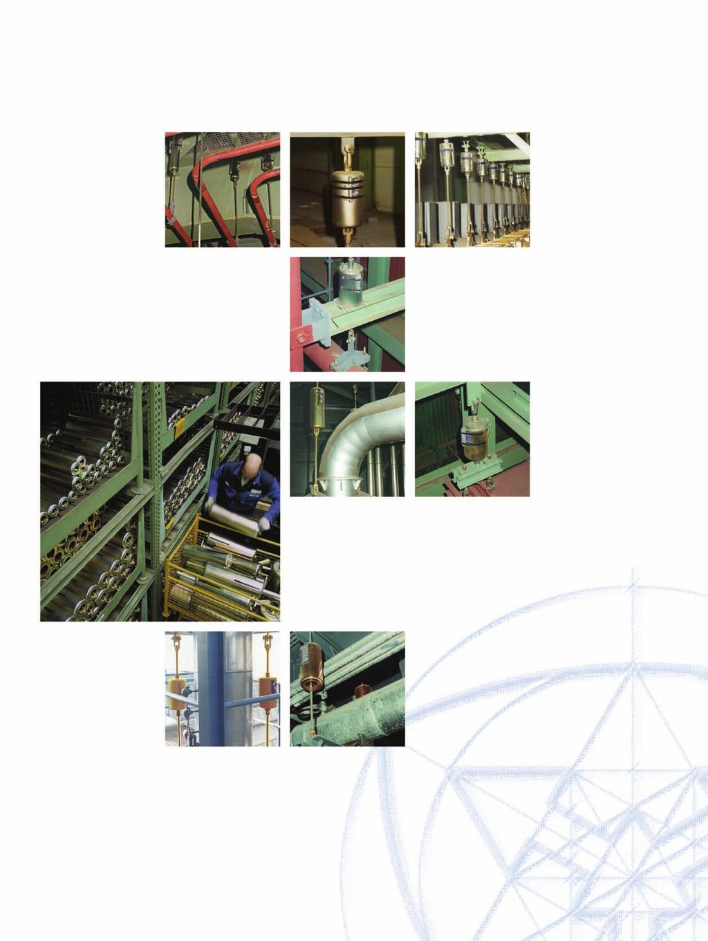
4 SPRING HANGERS SPRING SUPPORTS To prevent constraints in the system, thermal expansion in the piping and other piping components must not be hindered. The piping must therefore be supported in a correspondingly elastic manner. Spring hanger, type 1 Spring elements To compensate for slight vertical displacements in the piping, spring components are used as supports. The functioning of these components is based on preset helical coil springs which exert a variable supporting load over the whole range of movement corresponding to the given spring characteristics. Load variations resulting from this are limited through corresponding specifications based on stress calculations for the piping - this depends on the sensitivity of the system. The fundamental principles relevant for the function of the spring components are found in the MSS SP 58 and VGB R 5 L guidelines. See Technical Specifications, page 0.5. LISEGA spring hangers Various versions of spring elements, ideally suited to whatever structural requirements exist, are available. The optimum choice depends on the installation situation. Spring hangers, type 1 This type, the one most frequently used, is fitted with an upper connection for suspension. It is installed wherever the surrounding location offers a suitable connection point and sufficient space. The upper connections can be universally adapted with standard components to any given situation. Spring hangers, type This type is frequently used for its simple installation, just seating it on the existing steel. The connection is made by a rod passing through the unit. Spring supports, type 9 If the installation location does not permit suspension, then this model is a suitable alternative as a prop support. Where there is considerable horizontal displacement of the support load, and steel slides on steel, lateral forces can under certain conditions have an adverse effect on the operation of the support system. To take precautions against this, the use of PTFE bearings is recommended. In this case the counter bearing should have a stainless steel surface. 9 with PTFE slide plate. Spring hanger, type Recommended use of PTFE slide plates for spring supports type 9 Spring support, type 9.1
5 Angulating spring supports, type Unlike the spring support type 9, horizontal displacement can be taken up almost free of lateral forces by this design. This way that constraining frictional forces are completely excluded at all levels of movement, vertical and horizontal. Sway braces, type 7 These particular components act both in tension and compression and are used to stabilize the piping and other plant components. An additional damping effect is obtained at the same time. The connection parts correspond with those of Product Group 3. With LISEGA sway braces, type 7, the following adjustments can be made: load presetting free stroke installation dimension See also Installation and Operating Instructions, page.17 Load setting and blocking Spring hangers and supports are preset at the works to the installation load and blocked in both directions of movement. Blocking is necessary to take up additional loads during pickling, flushing, or hydrostatic tests. The factory settings are carried out on electronically controlled test benches: with spring hangers, values set at the factory are stamped onto a riveted name plate. the installation position is marked on the travel scale. cold and hot settings are marked on the travel scale with a white and red sticker respectively. the blocking device can be blocked in any position. The blocking pieces can be reinserted in any required position. Spring hangers and supports should be set in such a way that the spring load and the piping weight correspond with the cold load position. The corresponding hot load position results from the theoretically determined pipe movement (travel) and the spring rate. The load difference between the cold and hot positions acts on the piping as a reaction force and is limited by the relevant design specifications. Generally, the max. permissible load deviation amounts to % of the operating load. Above and beyond that, constant hangers exerting a constant supporting load over the whole travel range are to be used. Selection of spring hangers A decisive factor for the reaction force is the stiffness of the spring rate value of the respective coil springs. To cover the widest possible field of application using spring hangers, the load ranges are divided into 5 travel ranges. Please see Technical Specifications page 0. for details of usage. See also the selection table, pages.3 and.4, as well as Installation and Operating Instructions, page.. Design related advantages no welding (s, 1, 7) fully galvanized surfaces specially prerelaxed springs integrated tightening devices adjustable blocking system variable connection possibilities TÜV suitability test a wealth of experience from over a million applications Angulating spring support, type Sway brace, type 7 angulated arrangement Sway brace, type 7 single arrangement.
6 SELECTION OF SPRING ELEMENTS SELECTION CRITERIA FOR SPRING HANGERS AND SUPPORTS Permissible force variation The permissible force variation between cold load (installation load) position to hot load (operating load) position is limited internationally by common specifications for pipe stress analysis to max. % of the operating load. Maximum working travel Additionally, to preclude functional impairment due to instability from extra long springs, a working travel of maximum mm should not be exceeded. Spring rates To cover as wide a field of applications as possible while adhering to these standards, LISEGA spring elements are divided into 5 travel ranges with correspondingly different spring rates. Extra long springs Travel ranges 4 & 5 relate to extra long springs and should only be used after technical evaluation of the whole situation, especially in sensitive piping systems. Design types The selection of the suitable design type depends upon the respective support configuration or installation situation. Economical unit size To find the most economical size, the following procedures apply: Spring hangers type 1, Spring hangers type, Spring supports type 9, Angulating spring supports type Travel range Working travel (mm) C 9 C D. D. 9 D. D number Load (kn) Spring rate c (N/mm)
7 DETERMINATION OF THE MOST FAVORABLE SIZE 1. Selecting the ideal spring hanger Example: Operating load F = 00N Permissible deviation p % Travel (up) s = mm c % 00N = 0N/mm mm 0% Selection type 4 18 Spring rate c = 66.6N/mm Cold load F K = 00N. Determination of the percentage of force variation Example: 00N operation load, travel mm (up) A spring hanger type 4 18 was selected with a spring rate of c = 66.6N/mm mm 66.6N/mm 0% = 16.% 00N Spring hangers type. Variable spring hanger for seating type 6, spring supports type 8 Travel range Working travel (mm) number Load (kn) Spring rate c (N/mm) Travel range = 4th digit of type designation For availability of component type in the different travel ranges, see dimension table pages.5 to.11. The use of extra long springs is only to be recommended in limited cases because of the relatively large spring hysteresis..4
8 SPRING HANGER TYPE 1 Spring hangers type 1 C to 1 18 Dim E increases under load by the corresponding spring travel (see load table on page.3). In restricted spaces, spring hangers can be installed with trapeze type 79. See page. Spring hanger type Marking: Operating load/set load:...kn Working travel:... mm up/down.5 1 C 1 D 1 D A B d E H SW X M M M M M M M M M M16 M16 M16 M16 M M M M M4 M4 M4 M4 M4 M M M M M M M M M M M4 M4 M4 M4 M4 M48 M48 M48 M48 M Weight (kg)


 3 85 3 4")


9 SPRING HANGER TYPE blocking device Spring hangers type 11 to A B C d d3 E H R S SW1 SW X M56x4 M56x4 M56x4 M64x4 M64x4 M64x4 M68x4 M68x4 M68x4 M7x4 M7x4 M7x4 Mx4 Mx4 Mx Weight (kg) Dim E increases under load by the corresponding spring travel (see load table on page.4). Spring hanger type with weld-on clevis mounted. Spring hanger type with clevis mounted. Application in practice Spring hanger type.... Marking: Operating load/set load: kn Working travel: mm up/down.6


10 SPRING HANGER TYPE Spring hangers (seated) type D to Base plate 7 can be added to type on request. B C d6 E 7 D Load group D D A B d d4 H X max M M M M M M M M M16 M16 M16 M M M M4 M4 M4 M M M M M M M4 M4 M4 M48 M48 M Weight (kg) Spring hanger type.... Marking:.. Operating load/set load: kn Working travel: mm up/down.7 For special applications spring hangers type can be manufactured as trapeze units. Dims B and X reduce under load by the corresponding spring travel (see load table on page.3)

 5 3 0 3 3 3 4 3 4 5 5 5 7 Dims B and X reduce")
 Special spring assemblies for boiler support. Spring hanger type 6.... Marking:.")
11 SPRING HANGER TYPE 6 blocking device Spring hanger (seated) type 6 11 to A B d d4 H SW X max M56x4 M56x4 M56x4 M64x4 M64x4 M64x4 M68x4 M68x4 M68x4 M7x4 M7x4 M7x4 Mx4 Mx4 Mx Weight (kg) Dims B and X reduce under load by the corresponding spring travel (see load table on page.4) Special spring assemblies for boiler support. Spring hanger type Marking:.. Operating load/set load: kn Working travel: mm up/down.8
12 SPRING SUPPORT TYPE 9 Spring supports type 9 C to øl1 Load group øl1 16 C, D, , PTFE (Teflon) slide plates are recommended for considerable horizontal load displacements E Load group Suitable extensions can be ordered to bridge greater installation heights. 9 C 9 D1 9 D 9 D A B C d6 E F H D S Weight (kg) Spring support type Marking:.. Operating load/set load: kn Working travel: mm up/down Dim E is independent of the load setting. It varies under load by the corresponding spring travel (see load table page.3). Adjustment possibility +mm..9


13 SPRING SUPPORT TYPE 8 blocking device Spring supports type 8 11 to A B C ød d6 E F H S SW Weight (kg) Dim E is independent of the load setting. It varies under load by the corresponding spring travel (see load table page.4). Adjustment possibility + mm. Application in practice Spring support type Marking:.. Operating load/set load: kn Working travel: mm up/down.
14 ANGULATING SPRING SUPPORT TYPE Angulating spring supports type D to 9 14 weld-on bracket Weld-on brackets type are foreseen as connection parts (see page 3.8). Dim E is independent of the load setting. It varies under load by the corresponding spring travel (see load table, page.3). Adjustment possibility + mm. Connection type Angulating spring support type.... with weld-on brackets.... Marking:.. Operating load/set load: kn Working travel: mm up/down D A 5 1 d3 H R SG E F G Weight (kg) Weld-on bracket Installation extension for angulating spring support type D9 to Min. thread engagement Installation dimensions greater than E max on load reduction possible. Shorter L dimensions can be supplied, but then without adjustment possibility of 37.5mm. Extension for angulating spring support type.9.. L=... mm D A D d3 E min E max 4 4 L 37.5 min L 37.5 max weight at Lmin (kg) tube (kg/m)


 Dim E increases under load by the corresponding spring travel (see load table on page.")

 L= 00mm at travel range 1 3-16 1 6 6 9 7 38 41 48 63 68 76 99 1 8 17 9")
15 SPRING HANGER TRAPEZES TYPE 79 ø - Trapeze 79 D Nominal load (kn) d M M M M16 M16 M M M4 M4 M M M M M4 M4 M48 L max E at Travel range 1 3 U A B X Weight (kg) L= 00 at travel range per 0 mm The 4th digit of the type designation denotes the travel range of the spring hanger. 1=mm, =0mm, 3=0mm Permissible center load of the other load conditions see table page 0.5 (Nominal load 1 kn see load group 9) Dim E increases under load by the corresponding spring travel (see load table on page.3) The maximum L dimensions may be increased to 0mm, with load reduction of 5% for each 0mm of extension. Trapeze, type 79.. L= mm travel range 1 3 E dimension approx. 5 Spring Hanger trapezes type Notes... see above Trapeze 79 D Nominal load (kn) d M M M M16 M M4 M M M4 M48 L max B Weight (kg) L= 00mm at travel range per 0mm (kg) For restricted spaces the design shown can be manufactured as a special. Trapeze type L= mm.
16 SWAY BRACE TYPE 7 Sway brace type 7 D to 7 6 Maximum working travel mm including free stroke Weld-on bracket Load setting is carried out at the works in accordance with customer specifications. Dim E is independent of load setting. Adjustment possibility 37.5mm. Min. thread engagement Free stroke adjustment Load adjustment Weld-on brackets type and dynamic pipe clamps type or 37 are foreseen as connection parts. Sway brace type 7. Marking:... Operating load/set load: kn Working travel: mm up/down Nom. load Calibr. load [kn] Spring rate A (kn) min max (N/mm) C37.5 d3 E F H R SG 7 D weld-on bracket Weight (kg) Extension for sway brace type 7 D9 to 7 69 If requested, sway braces can be supplied with shopfitted extensions Min. thread engagement Installation dimensions greater than E max on load reduction possible. Shorter L dimensions can be supplied, but then without adjustment possibility of 37.5mm. Extension for sway brace type 7.9 L-dim.: mm 7 D A D d3 E min max L 37.5 Weight min max at Lmin (kg) tube (kg/m)
17 Function diagram upper articulated joint counter nut counter nut guide tube threaded tube counter nut guide rod name plate with travel scale travel scale lower ball bushing joint Load and installation length are adjustable to the corresponding specifications. compressive force neutral position tensile force Transfer of force on alternating direction of force..14

 Spring hangers and")


18 INSTALLATION AND OPERATING INSTRUCTIONS Spring hangers and supports are used to compensate for the thermal movement to be expected in piping systems. For trouble-free functioning, correct installation is essential, observing the following instructions: Spring hanger, type 1 (blocked) Spring hangers and spring supports types, 1,,, 6, 7, 8, 9 1. Transport and storage When transporting, threaded connections and travel stops must not be damaged. When stored in the open they should be protected from dirt and moisture.. Delivery condition Unless agreed otherwise, spring hangers and spring supports are delivered to the site blocked in the installation position. When hangers or supports are blocked (travel stop in both directions), the spring plate is locked by a special blocking device in the housing slots. All spring hangers and supports are supplied with a riveted aluminum name plate fitted with an integral travel scale. The following information is stamped on the name plate: order number if required set load theoretical travel spring rate of the hanger or support marking and position number test stamp if required The serial number is stamped directly on the housing. The blocking units for single spring models consist of a set of hinged metal plates. Individual plates can be swivelled into any desired blocking position. Blocking device for single spring models Spring hanger, type (blocked) Securing clamp Fixing bolt If specially ordered, the stops can be bolted securely to the hanger or support after deblocking. Spring support, type 9 (blocked) Name plate for spring hanger.


19 upper connection travel scale blocking unit with securing band name plate lower connection (turnbuckle with right-hand thread) counter nut On the travel scale, the theoretical operating position is marked with a red, and the theoretical cold position with a white sticker. Also, the position of the spring plate is marked with an X on the travel scale. The read out is made at the bottom edge of the spring plate..1 Spring hangers, type 1 Spring hangers, type 1, have upper and lower connections fitted with right-hand threads. At the top they consist of an internal thread engagement of limited depth, and at the bottom a turnbuckle. The threads are filled with grease and sealed with plastic caps. Angulated spring support, type. Spring hangers, type The upper connection of these hangers is supplied as a lug for a connecting pin. The lower connection consists of a turnbuckle with righthand thread..3 Spring hangers, type & 6 Spring hangers, type & 6 are provided with a fixed support tube to accommodate the connecting rod. Spring hanger, type.4 Spring supports, type 8 & 9 The spring supports are provided with either one or four adjustable support tubes fitted with a loosely mounted, but guided load plate. The support tubes are screwed in and the threads greased..5 Angulating spring supports, type The angulating spring supports are provided at the top with an adjustable support tube and a rotatable ball bushing joint, at the bottom with a fixed ball bushing joint. The joints provide a suitable connection to the corresponding weld-on brackets type. The support tube is screwed in and the threads greased. Spring hanger, type 6 Load chain with spring hanger Blocking device for heavy duty spring elements type to 8 Spring support, type 8.16
20 Sway brace, type 7.17 cold position Case 1 Attachment rods vertical during plant operation hot position hot position cold position Case Attachment rods vertical in installation condition.6 Sway braces, type 7 Sway braces are provided at the top with a length-adjustable ball bushing joint and at the bottom with a fixed lug suitable for connection to weld-on bracket type or dynamic clamp type or 37. Presetting of the load and if necessary the free stroke are carried out at the works in accordance with customer requirements. 3. Installation When installing, the rules given in Installation Instructions for Piping must also be observed. Special care must also be given to the installed position of the connecting rods over the whole support chain. Two possibilities are the norm: 1. The connecting rods are to be installed at an angle corresponding to the horizontal displacement to be expected. A vertical position of the rods is expected under normal operating conditions.. The connecting rods are to be installed vertically for easier checking. A controlled angled position under normal operating conditions is thereby permitted. In each case there should be unified rules and regulations for the whole plant. Connecting rods and points must be actuated by load at connection points. 3.1 Spring hangers, type 1 Connection is made by screwing the connecting rod into the upper threaded connection hole in type 1, and by screwing the lower connecting rod into the turnbuckle. As a tension range and length adjustment, the turnbuckle length available in the hanger can be used for the connecting rod. 3. Spring hanger, type Connection is made by pinning the lug to the upper attachment point and by screwing the lower connecting rod into the turnbuckle. As a tension range and length adjustment, the turnbuckle length available in the hanger can be used for the connecting rod. 3.3 Spring hangers, type & 6 These spring hangers are set on beams and correspondingly positioned. Once the precise position is defined the unit should be secured against horizontal movement. The load actuated connection is made via the connecting rod, which is led throught the support tube and tightened with a nut. 3.4 Spring supports, type 8 & 9 After positioning, these spring supports are connected to the structure by bolting or welding the base plate to the structure. Load distribution is applied through the load plate or through one or more adjustable load tubes. 3.5 Angulating spring supports, type The angulating spring supports are connected to the structure after corresponding positioning by welding the lower weld-on bracket. Load distribution is applied through the upper weld-on bracket via the pin connection to the height-adjustable load tube. 3.6 Sway braces, type 7 After positioning of the connection points, the weld-on brackets are attached and connection is made through the connection pins of the brackets or dynamic clamps. The ball bushing joints allow a 37.5mm adjustment of installation length. 4. Removing the travel stops The spring hangers and supports should only be deblocked when the set load is fully applied to all the supports, which form one system. If this is the case, the travel stops can easily be removed. If the travel stops are jammed, the load actually applied does not correspond with the theoretical adjusted load. (See Installation and Operating Instructions, Constant Hangers, page 1.3, item 4, in this regard).
21 5. Load readjustment 5.1 Spring hangers, spring supports For spring hangers the load can be readjusted by loosening or tightening the threaded rods at the lock nut. For spring supports, the load can be readjusted by a corresponding adjustment of the load tube. Under all circumstances, however, the appropriate technical department must be consulted before attempting any load readjustment. 5. Sway braces, type 7 Load readjustment is made by rotating the threaded tube (A). The large counter ring (B) is loosened to do this. In order to maintain the E dimension, the resulting gap is compensated for by readjustment of the guide tube. D C Spring hanger type with eye nuts as transport lugs B For sway braces, a free stroke can be set. To do this, the guide tube (C) opposite the inner guide rod (D) is to be unscrewed (loosen middle lock nut). The working travel reduces in the compression direction in accordance with the free stroke selected. A 6. Commissioning Before commissioning it must be checked that each hanger or support allows the precalculated movement of the piping. The working travel of the hanger or support can be read off at the bottom edge of the spring plate as travel in the blocking slots, and read directly off the travel scale. 7. Checking and maintenance The correct functioning of the spring hangers or supports can be checked in all operating situations by noting the position of the spring plates. Under normal operating conditions no maintenance is required. Hydraulic cylinder Hydraulic cylinder Hydraulic cylinder connecting rod counter nut lock nut load tube travel stop travel scale name plate Installation devices for readjustment of the set load for types, 6 and 8. The devices can equally well be used as deblocking aids. Example of an arrangement with type.18
Spring hangers, spring supports
 Spring hangers, spring supports 2 spring Spring hangers, supports PRODUCT 2 GROUP Spring hangers, spring supports Contents Page Field of application...2.1 Overview of spring hangers and spring supports...2.3
1 Variable spring supports Design Instructions
 Design Instructions 1.1 Application Rigid supporting structures are not capable to accommodate vertical displacement or large horizontal forced travels of piping. This nodes should be supported by spring
Pipe clamps, clamp bases, connecting parts
 Pipe clamps, clamp bases, pipe connecting parts 4 pipe Pipe clamps, clamp bases, connecting parts PRODUT 4 GROUP Pipe clamps, clamp bases, pipe connections ontents Page Field of application... 4.1 Product
STRUCTURAL ATTACHMENT ELEMENTS
 STRUCTURAL ATTACHMENT ELEMENTS 7 PRODUCT GROUP 7 STRUCTURAL ATTACHMENTS, TRAPEZES CONTENTS PAGE 0 Structural attachments, trapezes 7.1 Weld-on clevis type 73 7.2 Weld-on eye plate type 75 7.2 Weld-on
Constant hangers, constant supports
 Constant hangers, constant supports 1 Constant hangers, constant supports PRODUCT 1 GROUP Constant hangers, constant supports Contents Page Field of application...1.1 Advantages and design overview...1.3
ORDERING: Specify size, figure number, description, nominal pipe size or special O.D. and C-to-C dimension. C - C LOAD lb.
 Fig. 2110 www.pipingtech.com/fig2110 Sway Strut with 4 of Adjustment Engineered spring supports option 1 option 2 ORDERING: Specify size, figure number, description, nominal pipe size or special O.D. and
The GK units differ from the LK units in that the springs of the GK units have a spring eye at the front.
 01 09 Installation guidelines Mechanical suspension units GK LK GN0032-0 Mechanical suspension units GK LK The GK units differ from the LK units in that the springs of the GK units have a spring eye at
...our linkages, your solution. Rod Ends
 ...our linkages, your solution Technical Information Introduction All of our rod ends incorporate either a plain spherical bearing, ball bearing, or roller bearing. Below is an overview of each type. Plain
Technical specifications
 Technical specifications 0 Technical specifications Product 0 group Technical specifications Contents Page 1. Standard Supports, requirements and definition...0.1 2. LISEGA Standard Supports...0.1 3.
For advanced drive technology CLAMPEX. Shaft-hub-connection. KTR Precision joints CLAMPEX
 technology CLAMPEX Shaft-hub-connection CLAMPEX KTR Precision joints 227 technology Table of contents Page Brief information 228 Selection and calculation 25-255 CLAMPEX -Selection Shaft diameter = d 0
For advanced drive technology CLAMPEX. Shaft-Hub-Connection. KTR Precision Joints CLAMPEX
 technology CLAMPEX Shaft-Hub-Connection CLAMPEX KTR Precision Joints 07 technology Table of contents Page Brief information 09 Selection and calculation -5 CLAMPEX -Selection Shaft diameter = d 0 10 0
VARIABLE SPRING SUPPORTS BV35, BV70, BV140, BV210
 SUPPORTS 35, 70, 140, 210 GENERAL Variable spring supports are used for supporting pipework, vessels, columns and pipe connections to large tanks, that are subject to thermal movement and/or subsidence.
Contents. Sliding Door Gear Product information 155. Roller-Guided Sliding Door Gear. Page
 GEZE APOLL Contents Page Sliding Door Gear Product information 155 Roller-Guided Sliding Door Gear APOLL/Sliding doors 1-55 APOLL/Components 6-17 APOLL/End-folding doors 18-25 APOLL/Centre-folding doors
> piston force up to 20,1 kn. > operating pressure 250/350 bar. > chemically nitrided body. > piston force up to 44,0 kn. > operating pressure 350 bar
 Vertical and link CLAMPS for DEMANDING TASKS vertical CLAMP > piston force up to 20,1 kn > operating pressure 250/350 bar > chemically nitrided body link CLAMP > piston force up to 44,0 kn > operating
Technical Information TI-B10 Safety Brakes type KSP. 2 Function. Contents
 Technical Information SITEMA - Safety Brakes English translation of German original TI-B0-EN-0/0 Technical Information TI-B0 Safety Brakes type KSP High holding force by self-intensifying clamping Secure
INSTALLATION AND MAINTENANCE OF TOP LOADING ARM
 INSTALLATION AND MAINTENANCE OF TOP LOADING ARM D TABLE OF CONTENTS 1. INTRODUCTION 04 2. SPECIFICATION OF THE REDLANDS LOADING ARM 04 3. INSTALLING THE LOADING ARM 3.1. Installation Procedures 05 4.
Hydraulic Shock and Sway Suppressors ( Hydraulic Snubbers )
") Hydraulic Shock and Sway Suppressors ( Hydraulic Snubbers ) Hydraulic shock- and sway suppressors Applications PSS hydraulic shock- and sway suppressors are used to prevent damage to appliances, pipework,
Hydraulic Shock and Sway Suppressors ( Hydraulic Snubbers ) Hydraulic shock- and sway suppressors Applications PSS hydraulic shock- and sway suppressors are used to prevent damage to appliances, pipework,
PIPE HANGERS & SUPPORTS PRIVATE LIMITED Plot No 29 Industrial Estate Perungudi Chennai, Tamilnadu India
 PIPE HANGERS & SUPPORTS PRIVATE LIMITED Plot No 29 Industrial Estate Perungudi Chennai, Tamilnadu India-600096 Telephone +91 (0) 44-2496 1003, 2496 2668 Fax: +44 (0) 44-24961395 E mail: mengg@pipehangers.in
Installation and Operational Instructions for EAS - HTL housed overload clutch Sizes 01 3 Type 490._24.0
 Please read these Operational Instructions carefully and follow them accordingly! Ignoring these Instructions may lead to malfunctions or to clutch failure, resulting in damage to other parts. Contents:
Miniature Shock Absorbers SC²25 to SC²650 Self-Compensating
 Miniature Shock Absorbers SC²25 to SC²650 Self-Compensating 1 SC25EUM-5 SC25EUM-6 SC25EUM-7 SC75EUM-5 SC75EUM-6 SC75EUM-7 SC190EUM-5 SC190EUM-6 SC190EUM-7 SC300EUM-5 SC300EUM-6 SC300EUM-7 SC300EUM-8 SC300EUM-9
Shaft-Hub-Connections
 Stand: 14.01.2010 Shaft-Hub-Connections Shrink Discs Cone Clamping Elements Star Discs 36 Edition 2012/2013 RINGSPANN Eingetragenes Warenzeichen der RINGSPANN GmbH, Bad Homburg Table of Contents Introduction
ND DYNAMOC .STATIC STR INTS BERGEN-PATERSON PIPESUPPORT CORPORATION DESIGN INFORMATION WOBURN, MASSACHUSETTS 01888
 CATALOG 82 ENGINEERING SUPPLEMENT NO.3.STATIC ND DYNAMOC STR INTS DESIGN INFORMATION BERGEN-PATERSON PIPESUPPORT CORPORATION WOBURN, MASSACHUSETTS 01888 Bergen-Paterson markets the widest selection of
Pressure Reducing Valve Type 2114/2415
 Pressure Reducing Valve Type 2114/2415 Fig. 1 Type 2114/2415 1. Design and principle of operation The Type 2114/2415 Pressure Reducing Valve consists of the Type 2114 Valve and the Type 2415 Actuator.
Miniature Shock Absorbers SC190 to SC925 Soft-Contact and Self-Compensating
 Miniature Shock bsorbers SC190 to SC925 Soft-Contact and Self-Compensating 1 Operating Instruction SC190EUM-0 SC190EUM-1 SC190EUM-2 SC190EUM-3 SC190EUM-4 SC300EUM-0 SC300EUM-1 SC300EUM-2 SC300EUM-3 SC300EUM-4
Load Cell for Manually Operated Presses Model 8451
 w Technical Product Information Load Cell for Manually Operated Presses 1. Introduction... 2 2. Preparing for use... 2 2.1 Unpacking... 2 2.2 Using the instrument for the first time... 2 2.3 Grounding
NEOTECHA NTB-NTC BALL VALVES INSTALLATION AND MAINTENANCE INSTRUCTIONS
 Before installation these instructions must be fully read and understood 2 SAFETY Please also read through these notes carefully. 2.1 General potential danger due to: a. Failure to observe the instructions
Data Sheet T EN
 Data Sheet T 8015-1 EN Series 240 Types 3241 1 PSA, -7 PSA, -9 PSA Pneumatic Control Valves Type 3241 PSA Globe Valve Application Control valves for PSA plants (Pressure Swing Adsorption) Valve sizes DN
Installation and Operating Instructions for EAS -NC clutch Type 45_. _. _ Sizes 02 and 03
 Table of contents: Please read and observe this Operating Instruction carefully! A possible malfunction or failure of the clutch and any damage may be caused by not observing it. Page 1: - Table of contents
ROSTA MOTORBASES ROSTA. Self-Tensioning Motor Mount for Belt Drives. without slippage self-adjusting maintenance-free
 MOTORBASES Self-Tensioning Motor Mount for Belt Drives without slippage self-adjusting maintenance-free Technology Tensioning Motorbase Type MB for Belt Drives The elastic tensioning motorbase type MB,
BUTTERFLY VALVE WITH WELDED ENDS INSTALLATION AND MAINTENANCE MANUAL
 BUTTERFLY VALVE 31300 SERIES INSTRUCTIONS FOR INSTALLATION, USE AND MAINTENANCE 1. Overview Read these instructions carefully before starting the valve installation and start-up work. Safe keep the instructions
Axial Piston Fixed Pump A17FNO Series 10
 Axial Piston Fixed Pump A17FNO Series 10 RE 91510 Issue: 06.2012 Replaces: 03.2010 Size 125 Nominal pressure 250 bar Maximum pressure 300 bar For commercial vehicles Open circuit Features Fixed pump with
Model R. q Fig. 81-H: Standard Type: q A, q B, q C, q D, q E, q F. q Fig. C-81-H: Corrosion Resistant CONSTANT SUPPORTS.
 OSA SUPPORS odel R q Fig. 81-: Standard : q A, q, q, q, q, q F q Fig. -81-: orrosion Resistant : q A, q, q, q, q, q F onstant Support Finish: Standard finish; painted with semi gloss primer. orrosion resistant;
Roller chain idler sprocket units Idler pulley units
 Roller chain idler sprocket units Idler pulley units Roller chain idler sprocket units, idler pulley units Page Product overview Roller chain idler sprocket units, idler pulley units... 334 Design and
OPERATIONS MANUAL LEVER CHAIN HOIST
 OPERATIONS MANUAL LEVER CHAIN HOIST IMPORTANT SAFETY INFORMATION Please read, understand and follow all safety information contained in these instructions prior to the use of this hoist. Retain these instructions
The gear boxes can be run at the same speeds as the actuator models. Do not exceed torque ratings.
 1. What is the lifting torque required? The lifting torque for a single actuator depends on the load, the worm gear ratio, type of screw (machine cut or ball screw) and the pitch of the lifting screw.
LOCKED SERIES. Machine Failures. General Information. set up. maintenance. reconditioning. repair 30.4%
 General Information LOCKED SERIES 2 Lowering machinery process costs is key in today s world. According to a recent study approximately a third of all machine stoppages result in unexpected damage and
Pneumatic Controller for Temperature. Type Pneumatic Controller for Temperature. Type Mounting and Operating Instructions EB 7065 EN
 Pneumatic Controller for Temperature Type 3301 Pneumatic Controller for Temperature Type 301-1 Mounting and Operating Instructions EB 7065 EN Edition January 2014 Definition of the signal words used in
Heavy-Duty Rod Ends - Male with integral spherical plain bearing
 Heavy-Duty Rod Ends - Male with integral spherical plain bearing 65700 Order No. Thread (hand) d 1 l 1 d 2 d 3 d 4 l 2 l 3 X g H7 65700.W0005 Right 5 33 M 5 11,11 18 20 9 14 65700.W0006 Right 6 36 M 6
Precision Modules PSK
 Precision Modules PSK The Drive & Control Company Rexroth Linear Motion Technology Ball Rail Systems Roller Rail Systems Standard Ball Rail Systems Super Ball Rail Systems Ball Rail Systems with Aluminum
ROSTA Tensioning Motorbases Type MB. self-adjusting maintenance-free overload-proof non-slip dampen harmful vibrations extend belt drive
 Technology ROSTA Tensioning Type MB for Belt Drives The ROSTA elastic tensioning motorbase type MB, with the rubber suspension unit as swivel mounting, compensates continuously for all stretching, hopping,
PRECISMECA - MONTAN Gesellschaft für Fördertechnik mbh. Documentation Operating Instructions. Rollers
 PRECISMECA - Gesellschaft für Fördertechnik mbh Documentation Operating Instructions Rollers Operating Instructions Index No.: T311-00 Page: 1 of 1 Section Document No. Pages Preface Safety Technical data
Selection Tool. on the Internet at in the section MÄDLER -Tools. Other sizes and designs on request. Connecting Shafts Page 766
 Couplings Overview Friction Clutches Friction Clutches Type B Axial Arrangement Friction Clutches Type C Transversal Flexibility Sliding Hubs with Torsionally-Flexible Coupling Multi-Disk Friction Clutches
Interlocks 200 Series
 rd 12070 43 St. NE, St. Michael, MN 55376 763-497-7000 www.tcamerican.com sales@tcamerican.com Installation Instructions Interlocks 200 Series 2I-515; 2I-930 2I-513; 2I-850 Crane Interlock and Operating
LIGHTWEIGHT AND COMPACT. SERIES SL Nm. single-position multi-position. THE ultimate COUPLING from Nm
 LIGHTWEIGHT AND COMPACT L SAFETY COUPLINGS TOQLIGHT SEIES SL 5 700 Nm THE ultimate COUPLING from 5 700 Nm SEIES SL DESIGN / FEATUES Extremely lightweight construction Up to 60 % weight reduction in comparison
V SWISS MADE LINEAR TECHNOLOGY
 Compact units Excerpt from main catalogue SWISS MADE LINEAR TECHNOLOGY V 11-15 Line Tech compact units Table of contents Product overview 106 107 Design fundamentals / Lubrication / Maintenance 108 Profile
Product overview. Joints. Circlips for ball seats DIN K0714. Quick plug couplings with radial offset compensation K0709. Page 837.
 Joints 825 Product overview Joints Quick plug couplings with radial offset compensation K0709 Quick plug couplings with radial offset compensation and screw-on flange K0710 Quick plug couplings with angular
Compact Modules. with ball screw drive and toothed belt drive R310EN 2602 ( ) The Drive & Control Company
 The Drive & Control Company") with ball screw drive and toothed belt drive R310EN 2602 (2007.02) The Drive & Control Company Bosch Rexroth AG Linear Motion and Assembly Technologies Ball Rail Systems Roller Rail Systems Linear Bushings
with ball screw drive and toothed belt drive R310EN 2602 (2007.02) The Drive & Control Company Bosch Rexroth AG Linear Motion and Assembly Technologies Ball Rail Systems Roller Rail Systems Linear Bushings
These installation and maintenance instructions must be read in full and completely understood before the installation!
 These installation and maintenance instructions must be read in full and completely understood before the installation! 1. General information on the installation and maintenance instructions These instructions
PIPE HANGERS & SUPPORTS PRIVATE LIMITED Plot No 29 Industrial Estate Perungudi Chennai, Tamilnadu India
 PIPE HANGERS & SUPPORTS PRIVATE LIMITED Plot No 29 Industrial Estate Perungudi Chennai, Tamilnadu India-600096 Telephone +91 (0) 44-24962668, 24961003 Fax: +44 (0) 44-24961395 E mail: mengg@pipehangers.in
PIPINGSOLUTIONS, INC.
 Piping Stress Analysis Where do I start? The following information will take you step-by-step through the logic of the data collection effort that should occur prior to beginning to model a piping system
SECTION 11 INTERMODAL EQUIPMENT
 SECTION 11 INTERMODAL EQUIPMENT ROA MANUAL SCHEDULE OF AMENDMENTS SECTION 11 AMENDMENT NUMBER PAGES AMENDED AMENDMENT SUMMARY DATE ISSUED TABLE OF CONTENTS Section Description Page No. 11.1 SCOPE... 11-1
Spiroflex spiral-wound gaskets
 Spiral-wound gaskets have long been used as sealing elements in refineries, chemical plants, gas installations, water treatment plants and in general pipeline construction. Spiroflex gaskets SpV retain
Fisher 1051 and 1052 Style H and J Sizes 40, 60 and 70 Rotary Actuators
 Instruction Manual 1051 and 1052 H & J Actuators Fisher 1051 and 1052 Style H and J Sizes 40, 60 and 70 Rotary Actuators Contents Introduction... 1 Scope of Manual... 1 Description... 2 Specifications...
Interlocks 325 Series
 rd 12070 43 St. NE, St. Michael, MN 55376 763-497-7000 www.tcamerican.com sales@tcamerican.com Installation Instructions Interlocks 325 Series 3I-615; 3I-430 3I-613; 3I-450 Crane Interlock and Operating
Suspension. Table of Contents
 Suspension Table of Contents Sub-Headings Safety Notice 2 Explanation of Signal Words 2 Danger 2 2 Caution 2 Description 3 Preventive Maintenance 4 Shock Absorber 7 Visual Inspection 7 Heat Test 8 Steering
PIPE SUPPORTS INDIA PRIVATELIMITED Plot No 29 Industrial Estate Perungudi Chennai, Tamilnadu India
 PIPE SUPPORTS INDIA PRIVATELIMITED Plot No 29 Industrial Estate Perungudi Chennai, Tamilnadu India-600096 Telephone +91 (0) 44-24952668, 24961003 Fax: +44 (0) 44-24961395 E mail: psindia@vsnl.com www.pipesupports.com
TORQLIGHT SAFETY COUPLINGS
 LIGHTWEIGHT AND COMPACT single-position TOQLIGHT SAFETY COUPLINGS SEIES SL 10 700 Nm THE ULTIMATE COUPLING FOM 10 700 Nm SEIES SL DESIGN / FEATUES Extremely lightweight construction Up to 60 % weight reduction
V SWISS MADE LINEAR TECHNOLOGY
 Excerpt from main catalogue inear modules V 11-15 SWISS MDE INER TECHNOOGY ine Tech inear modules Table of contents Product overview 6 7 Design fundamentals / ubrication / Maintenance 8 Profile cross-sections
3D TOUCH. Extruder upgrade. Document version 1.0
 3D TOUCH Extruder upgrade Document version 1.0 1 Summary This manual is for the installation of an additional extruder into the 3D Touch. The procedure is the same for both 1 2 head, and 2 3 head upgrades.
SITEMA PowerStroke. Technical Information TI-P12. 1 Function. 2 Applications. Mould Closing Devices series FSKP. Contents. Technical Information
 Technical Information SITEMA PowerStroke FSP ocking, actuating and releasing by pneumatic pressure TI-P1-EN-0/016 English translation of German original Technical Information TI-P1 SITEMA PowerStroke Mould
Mounting and Operating Instructions EB 8097 EN. Type and Type Pneumatic Control Valves
 Type 3347-1 and Type 3347-7 Pneumatic Control Valves Type 3347-7, cast body with welding ends Type 3347-7, bar stock body with threaded connections Mounting and Operating Instructions EB 8097 EN Edition
Piezoresistive Absolute Pressure Sensor
 Pressure Piezoresistive Absolute Pressure Sensor Miniature Sensor for Research and Development Type 4005B... Universal pressure sensor for measuring absolute pressur in ranges from 0... 5 to 0... 250 bar.
Pipe hanger solutions
 Product catalog Middle East offering Pipe hanger solutions for commercial and industrial applications B00 series B00 - Standard clevis hanger Pipe will not pinch when installing. 5 swing in either direction
ROSTA Tensioning Motorbases Type MB. self-adjusting maintenance-free overload-proof non-slip dampen harmful vibrations extend belt drive
 83 Technology ROSTA Tensioning Motorbase Type MB for Belt Drives The ROSTA elastic tensioning motorbase type MB, with the rubber suspension unit as swivel mounting, compensates continuously for all stretching,
Mounting and operating instructions EB 8093 EN. Series 240 Pneumatic Control Valve for Cryogenic Temperatures. Type and
 Series 240 Pneumatic Control Valve for Cryogenic Temperatures Type 3248-1 and 3248-7 Fig. 1 Type 3248 Cryogenic Valve with Type 3277 Pneumatic Actuator as globe and angle valve Mounting and operating instructions
MECHANICAL Forging PRESSES WITH KNUCKLE-JOINT
 MECHANICAL Forging PRESSES WITH KNUCKLE-JOINT MML / MSL. Mechanical Forging Presses with knuckle-joint. From process development and cost-effective line concepts to full production lines. MECHANICAL Forging
 DRUM BRAKE RIMS Periodic inspection of drum brake rims is necessary to determine indications of uneven or excessive wear. In general, brake rim failures other that regular wear are caused by brake linings
Product overview. 10 Bosch Rexroth Corporation Compact Modules R310A 2602 ( ) Compact Modules CKK. Compact Modules with ball screw drive (CKK)
 Compact Modules CKK. Compact Modules with ball screw drive (CKK)") 10 Bosch Rexroth Corporation R310A 2602 (2008.09) CKK with ball screw drive (CKK) Product overview are precision, ready-to-install linear motion systems characterized by their high performance and compact
10 Bosch Rexroth Corporation R310A 2602 (2008.09) CKK with ball screw drive (CKK) Product overview are precision, ready-to-install linear motion systems characterized by their high performance and compact
Installation and Operation Instructions RINGFEDER Type 2050 AM RINGFEDER Type 2050 AP
 Installation and Operation Instructions RINGFEDER Type 2050 AM RINGFEDER Type 2050 AP 22.10.2003 10069125 Type 2050 AM General RINGFEDER Type 2050 AM, part no.: 14994532 RINGFEDER Type 2050 AP, part no.:
Ball Rail Systems RE / The Drive & Control Company
 Ball Rail Systems RE 82 202/2002-12 The Drive & Control Company Rexroth Linear Motion Technology Ball Rail Systems Roller Rail Systems Standard Ball Rail Systems Super Ball Rail Systems Ball Rail Systems
2. Remove front wheels.
 Read all instructions before beginning work. Following instructions in the proper sequence will ensure the best and easiest installation. Thank you for purchasing Maximum Motorsports Caster/Camber Plates.
SITEMA PowerStroke. Technical Information TI-P11. 1 Function. 2 Applications. Mould Closing Devices series FSK. Contents
 SITEMA PowerStroke FS ocking, actuating and releasing by hydraulic pressure English translation of German original Technical Information TI-P11 SITEMA PowerStroke Mould Closing Devices series FS TI-P11-EN-01/016
SUPER TYPE PILLAR FITTING INSTRUCTION MANUAL
 MANUAL No. 048L-1 SUPER TYPE PILLAR FITTING INSTRUCTION MANUAL This instruction manual contains safety information. Please read this manual carefully to ensure safe and correct use of the product. This
ORIGA Pneumatic Linear Drives OSP-L
 ORIGA Pneumatic Linear Drives OSP-L Very long lifetime and lowest leakage A NEW Modular Linear Drive System With this second generation linear drive Parker Origa offers design engineers complete flexibility.
CALIPER BRAKE INSTALLATION AND MAINTENANCE MANUAL
 CALIPER BRAKE INSTALLATION AND MAINTENANCE MANUAL WPT Power Corporation 1600 Fisher Road - Wichita Falls, TX 76305 P.O. Box 8148 - Wichita Falls, TX 76307 Ph. 940-761-1971 Fax 940-761-1989 www.wptpower.com
Precision Modules PSK
 Precision Modules PSK 2 Bosch Rexroth AG Precision Modules PSK R999000500 (2015-12) Identification system for short product names Short product name Example:: P S K - 050 - N N - 1 System = Precision Module
Servo-pneumatic drive solution for welding guns. Top quality welding!
 Servo-pneumatic drive solution for welding guns Sturdy and precise! Top quality welding! Highlights Extremely short cycle times High quality and outstanding reproducibility of the spot welds Excellent
Model 320 / 320A Hinge Assembly
 MANUFACTURING CO. THE FIRST NAME IN QUALITY COUPLINGS Installation, Inspection, Operation & Maintenance Guide Model 320 / 320A Hinge Assembly IMPORTANT Read these instructions completely before installing,
SD Bendix Manual Slack Adjusters DESCRIPTION ADJUSTING MECHANISM OPERATION
 SD-05-1200 Bendix Manual Slack Adjusters WORM SHAFT (LOCK SCREW) FIGURE 1 - POSITIVE LOCK TYPE SLACK ADJUSTER DESCRIPTION In an s-cam type foundation brake, the final link between the pneumatic system
Axial Piston Fixed Pump A17FNO
 Electric Drives and Controls Hydraulics Linear Motion and Assembly Technologies Pneumatics ervice Axial Piston Fixed Pump A17FNO RE 91510/03.10 1/12 Data sheet eries 10 ize 125 Nominal pressure 250 bar
External Gear Pumps Series F
 External Gear Pumps Series F RA 10089/08.11 Replaces: RA 10097 1/60 AZPF-... Fixed pumps Size 4.0...28 cm 3 /rev (.25-1.71 in 3 /rev) Overview of contents Contents Page General 2 Product overview 3 single
Elastomeric Bearings & Industrial Products. Elastomeric Bearings & Industrial Products. EA Bearings. EA Bearings. EA Series Standard Bearings
 EA Bearings EA Bearings EA Series Standard Bearings Support and Installation Part Number These bearings are designed to support a vertical load up to 2000kN with the constant bearing temperature not exceeding
Technical Information
 Product Group: TRAILERS Model: ALL MODELS This bulletin is provided for technical reference and service related updates. If you have any questions, comments or do not wish to receive these e-mails, please
Owners manual. Öhlins Superbike front fork FG 170
 Owners manual Öhlins Superbike front fork FG 0 Including: Setting up your fork Changing springs and seals Service the fork Trouble shooting Technical info Spare parts & tools Öhlins super bike front fork
B Precision Ground Plates and Flat Bars. E Ground Precision Components. G Elastomer-Bars, -Sheets, -Sections
 A Die Sets B Precision Ground Plates and Flat Bars C Lifting and Clamping Devices Shanks, Lifter Studs and Lifting Hooks, Eyebolts Clamping Claws, Screws and Bolts D Guide Elements E Ground Precision Components
PIPE HANGERS AND SUPPORTS
 THE GROUP With 24 companies in 19 countries Witzenmann is number 1 in the industry worldwide. PIPE HANGERS AND SUPPORTS World leader Witzenmann is a global group specialising in the design and manufacture
Profi le rail guides LLR
 Profi le rail guides LLR Content The SKF brand now stands for more than ever before, and means more to you as a valued customer. While SKF maintains its leadership as the hallmark of quality bearings throughout
V-Rings around the clock... around the clock...
 Description V-rings are rotary seals that can perform numerous jobs in their function of sealing rotating shafts: sealing against the penetration of dirt, dust, water or watery pollutants, combination
SwayPro. NOTE: A minimum tongue weight of 200 lbs. is required THANK YOU
 SwayPro Owner s Manual & Installation Instructions Serial Number Standard Hitch Head w/ Clamp-On Rotating Latches BXW0350 350 lbs. maximum tongue weight capacity BXW0550 550 lbs. maximum tongue weight
L Standard Parts for Mould Making
 A Die Sets B Precision Ground Plates and Flat Bars C Lifting and Clamping Devices Shanks, Lifter Studs and Lifting Hooks, Eyebolts Clamping Claws, Screws and Bolts D Guide Elements E Ground Precision Components
Installation and Operating Instructions for ROBA -ES couplings Type 940. _. _ Sizes 14-48
 Table of contents: Please read and observe this Operating Instruction carefully. A possible malfunction or failure of the clutch and damage may be caused by not observing it. Page 1: - Table of contents
Standard with cone bushing. Backlash-free Safety Clutch
 EAS -Compact ratchetting clutch/synchronous clutch The Backlash-free Safety Clutch for Standard with cone bushing Packaging Machinery Machine Tools Paper Machinery Indexing Drives Servo Motors EAS -NC
Piezoresistive Pressure Sensor
 Pressure Piezoresistive Pressure Sensor Miniature Sensor for Research and Development Type 4005B... Universal pressure sensor for pressure measurement up to 250 bar absolute. ø2,7 Precize pressure measurements
RE / STAR Tolerance Rings STAR Ball Knobs, Knob and Lever Type Handles
 RE 2 970/.99 STAR Tolerance Rings STAR Ball Knobs, Knob and Lever Type Handles STAR Tolerance Rings Product Overview Tolerance rings are made of hard, embossed spring steel strip and belong to the class
Front mechanical suspensions
 FRONT MECHANICAL SUSPENSIONS 9 PRINT 603.43.351/D Front mechanical suspensions Page DESCRIPTION... 11 ARTICULATED QUADRILATERAL SUSPENSION WITH TRANSVERSE LEAF SPRING... 11 SPECIFICATIONS AND DATA... 12
Online version - not for reprint
 4. CLUTCH, CHAIN DRIVE, CHAIN BRAKE, CHAIN TENSIONER 4. Clutch Drum/Chain Sprocket 43RA007 VA 70RA005 VA - Remove the chain sprocket cover. Disengage the chain brake by pulling the hand guard toward the
High precision dual rubber coupling STEPFLEX STF
 High precision dual rubber coupling STEPFLEX STF STEPFLEX High-damping couplings Our newly developed laminated rubber element achieves high damping and low reaction force. Their unitized construction with
Ball. Ball cage. Fig.1 Structure of Caged Ball LM Guide Actuator Model SKR
 Caged all LM Guide Actuator Model Inner block all screw shaft Grease nipple Outer rail all cage all Structure and Features Fig.1 Structure of Caged all LM Guide Actuator Model Caged all LM Guide Actuator
Pressure Relief Valve DB12 CE
 Pressure Relief Valve DB12 CE up to 120 l/min Connection housings 1. DESCRIPTION 1.1. GENERAL According to DIN-ISO 1219, HYDAC pressure relief valves DB12-CE are valves for oil hydraulic systems to control
q Quadruple Spring: Standard Type: q A, q B, q C, q D, q E, q F, q G q Quadruple Spring-CR: Corrosion Resistant SPRING HANGERS
 q Quadruple Spring: Standard Type: q A, q, q, q, q E, q, q G q Quadruple Spring-R: orrosion Resistant Type: q A, q, q, q, q E, q, q G Quadruple Spring Hangers esign features: Precompression. Precompressing