Constant hangers, constant supports
|
|
|
- Thomasina Palmer
- 6 years ago
- Views:
Transcription
1 Constant hangers, constant supports 1 Constant hangers, constant supports PRODUCT 1 GROUP


2
3 Constant hangers, constant supports Contents Page Field of application Advantages and design overview Mode of operation and function Design features Function testing Installation overview PRODUCT1 GROUP 2 Selection overview Selection tables Constant hangers type Support bearings type 71 for constant hangers type Constant hangers types Support bearings type 71 for constant hangers types Constant hangers type Constant supports type Angulating constant supports type Selection tables special designs Constant hanger trapezes type Heavy constant supports type Servohangers type Installation and operating instructions

. In the case of greater vertical displacement the use of constant hangers or constant supports is required.")

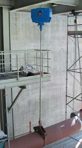
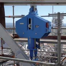
4 Field of application To avoid unacceptable forces and moments in pipe systems, the thermal expansion of the piping must not be restricted. Constant hangers types 11-14, Constant supports type 16 Minor thermal displacement in the pipe systems in the vertical direction can be compensated by spring supports or spring hangers. Due to the resulting proportionally increasing force deviation corresponding to the spring rate, their use is limited to a displacement range specified by the designer (see Product Group 2, pp 2.5 and 2.6). In the case of greater vertical displacement the use of constant hangers or constant supports is required. For these special designs, the spring force is transformed into a constant force throughout the displacement range (see function principle, p. 1.5). The proportional loads of the pipe system can in this way be constantly distributed over the whole displacement range without significant deviations. As a rule, for LISEGA constant hangers the use of type 11, tried and tested over 100,000 times, provides the standard solution. Constant hanger type 11 The function principle is based on the arrangement of three springs resulting in the parallelogram of forces. The design is distinguished by highly functional accuracy along with wide load adjustment ranges. The favorable powerto-weight ratios and symmetrical designs enable easy installation. For further typical advantages, see p Constant hanger in a coal-fired power station Final assembly of a constant hanger Installation inspection of a constant hanger 1.1


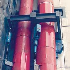
5 Constant hanger type 18 As a rule, the pipe support engineer allows for sufficient installation space for the supports required. However, due to limitations of space the installation height can be too small for the typical standard solution with type 11. This sometimes occurs, especially when replacing existing installations. To provide the optimum solution in such cases, type 18, a low profile design, is available from the LISEGA hanger range, beside the main type 11 series. The function principle of this design is based on the lever principle. Unlike the usual leverarm type hangers, the load displacement here is linear and is constant, following the LISEGA principle (see function principle, p. 1.6). In the case of constant hangers, the pipe systems are suspended from roof constructions or the steelwork. If the piping is laid out near ground level it may be appropriate to take up the loads from below with constant supports. Constant support type 19 Due to its compact design, constant support type 19 thereby replaces its predecessor, type 16, as standard. Type 16 continues to be standard only in the heavy-duty range (load range kN) for its coupling capacity. Constant hanger type 18 On the basis of their special function principles and modes of design, LISEGA constant hangers and supports have, for the past five decades, proven their outstanding operational safety and reliability many thousands of times. Further descriptions of their mode of operation and function are set out on p. 1.6 and their design features from p Constant support type 19 1 For the operational safety and long life of the pipe systems and hence of the plant itself, the consistent functional accuracy of the constant hangers is of utmost importance. In comparison with conventional lever-arm type hangers the new LISEGA type 18 is lower profile and enables the creation of support chains in the smallest of spaces. Space-saving design of type 18 compared to a conventional lever-arm hanger 1.2
6 Special benefits of LISEGA constant hangers and supports The user can profit from a variety of special benefits where LISEGA constant hangers are concerned. Significant savings are possible, especially regarding labor-intensive ancillary support costs such as planning, installation and operation Constant hanger type Constant hanger type Constant support type 19 axis of symmetry Principle-based constancy by way of a special function principle. 2 Pre-relaxed springs eliminate any significant loss of load-bearing capacity. 3 Reduced friction due to minimized number of bearing points. 4 Especially wide load adjustment range avoids hanger replacement when operational loads change. 5 Turnbuckle function allows greater adjustment of pipe installation position. 6 Load application free of moments due to a single suspension point. 7 Blocking is adjustable to practically any travel position through fine-tooth notching. 8 Name plate contains complete technical specifications. 9 Directly readable travel scale with marking for hot/cold load positions. 10 Load scale with permanent marking of adjustment load. Symmetrical design ensures direct flow of forces through axis of symmetry. Favorable power-weight ratios for reduced installation loads. Arranged by load groups and travel ranges to simplify selection (modular system). Consistent functional behavior due to highquality corrosion protection and maintenance-free chemically nickelized finishes. Readily adaptable to installation situation via corresponding designs and standardized accessories. Double load-tube guiding of constant supports for transmission of side loads. Secure connection of load chains due to load- and connection-compatible modular components. 1.3


 is available on request. If no space restrictions or other specifications are to be considered, this is the preferred product.")

 and is especially suitable in restricted spaces.")
7 1 LISEGA constant hanger and support types As fixed elements in the pipe system concept, the pipe supports must operate smoothly as functional connections between the pipe system and the surrounding structure. Type 11 Pipe systems are usually very complex layouts with restricted space. To allow for optimum use of the different spatial conditions, various designs are available as standard for the different application situations. All components are available either from stock or at short notice. Constant hanger type 11 C3 19 to Standard design for use as suspension for loads up to load group 9 (100kN) and travel range 6 (750mm). Travel range 7 (900mm) is available on request. If no space restrictions or other specifications are to be considered, this is the preferred product. Constant hanger type 11 with support brackets type 71 C3.1 to Standard design with support brackets bolted at the LISEGA factory for use as seated versions. Type 11 with support brackets Constant hanger type 18 D3 17 to Serial standard design in special low profile version as alternative suspension instead of type 11, if the installation height is limited. Constant support type 19 D3 17 to Serial standard design for use as support if constant support from below is required. Type 18 Note: This version replaces the taller single-cell constant hanger type 16 (see Standard Supports Catalog 2010) and is especially suitable in restricted spaces. Type 16 can still be supplied if required. Heavy constant support type 16 Special design as multi-cell constant support type 16, if heavy loads have to be distributed. Type 19 Servohanger type to Servohangers are equipped with additional active load regulation and can reduce overloading in the piping system to a permissible harmless level. Type 17 with support brackets Type


8 WIRKUNGSWEISE UND FUNKTION F 2 E F2 D E C D C B BA F A F E C D B F1 A F Mode of operation and function Types 11, 12, 13, 14, 16, 79 Obere Stellung Mittlere Stellung Besondere Anforderungen An die zuverlässige Funktion von Konstanthängern sind strenge Anforderungen zu The LISEGA Function Principle stellen: The LISEGA Function Principle is based on the exakte Konstantheit interaction bei jeder of the force from a mainspring and Lasteinstellungthe resulting force of two connected balance minimierte mechanische springs. The Reibungskräfte force directions of the pre-loaded compensating springs are thereby angled Ebenso sind für die against laufende each Überwachung other in the shape of a parallelogram of besondere forces. Vor- des Rohrleitungsverhaltens aussetzungen zu erfüllen: zuverlässige Kontrollanzeigen The suspended für load F acts directly on the Einstelllast und mainspring Wegstellung B via the load tube A. The preloaded compensating springs C act additionally ausreichende und präzise on the load tube as the resulting force F2 Nachstellmöglichkeit der Last via pivoting cams D and roller supports E. The mainspring force F1 and the resulting force Das LISEGA-Funktionsprinzip F2 change on the shifting of the load over the Für die Erfüllung der Anforderungen bietet displacement range in accordance with the das patentierte LISEGA-Funktionsprinzip die besten Voraussetzungen. specified Hiernach spring beruht constants, the cam path, and die Wirkungsweise the auf angular dem Zusammenwirken der Kraft aus einer Hauptfeder und der position of the cam components. resultierenden Kraft The zweier course zugeschalteter of the resulting force corresponds Ausgleichsfedern. Die Kraftrichtungen der to the characteristics of the mainspring. In this vorgespannten Ausgleichsfedern sind dabei nach Art eines Kräfteparallelogramms way the mainspring winklig force is balanced out, gegeneinander gerichtet. without deviations, to a constant support force. F2 D C E B F1 A F G Funktionsweise der LISEGA-Konstanthänger Untere Stellung = = = =75 F Die anhängende Last J The F wirkt LISEGA über das function principle leads to Lastrohr A direkt auf die Hauptfeder B. Die Vorspannkräfte der absolute Ausgleichsfedern constancy which by theory can C wirken als resultierende easily Kraft be proven. F2 über schwenkbare Kurventeile D und die Stützrollen E zusätzlich auf das J Lastrohr. The LISEGA Die Hauptfederkraft F 1 und die Resultierende F2 verändern function principle permits an especially wide load adjustment range of sich bei Verschiebung der Last über den Bewegungsbereich s entsprechend 40% 100% den of vorgegebenen Federkonstanten, der Kurvenbahn the nominal load. und der Winkelstellung der Kurventeile. Der Verlauf der Resultierenden entspricht exakt der Kennlinie der Hauptfeder. Dadurch wird die Kraft der Hauptfeder ohne Abweichungen zu einer konstanten Stützkraft ausgeglichen. Load adjustment The load adjustment is carried out by a preloading of the mainspring. As the characteristics of the resulting balancing force and the mainspring are the same, only a linear shifting of the initial force thereby occurs F1. This way, the change in force is the same at every point of the movement and the ultimate load remains constant at each load setting. Adjustment screws The remaining travel range changes proportionally to the load alterations. 1.5


9 1 Mode of operation and function Types 18, 19 A C B D F A B C D F A B D C F Function principle for LISEGA constant hangers type 18 and constant supports The function principle is based on the lever principle, by which variable spring forces are transformed into a constant support force by way of lever mechanics. Two lever arms A, symmetrically arranged at an angle to each other, thereby act as one system with pre-loaded springs B. On a vertical change in position of the load F to be taken up, the displacement is distributed over rollers C and defined bearing surfaces onto the lever systems. Through the pairing arrangement of the levers the displacement runs linearly in the axis of symmetry, whereby the lever conditions that thereby change do so proportionally to the correspondingly changing spring preloading. In this way the load stays in balance with the adjusted load in every travel position. Sinus-shaped load deviations from the lever movement in the form of an arc are balanced by correspondingly machined cam profiles. This way the load distribution is held constant with mathematical accuracy in every position. Load adjustment The calibration load is adjustable within a range of approx. 50% to 100% of the maximum hanger force. By way of an adjusting screw D the length of the lever arm force is continuously variable. On all load settings the available travel range remains unchanged. The whole working travel range is always available. Spring force Lever arm Leverage Load arm Load 1.6

 has a defined engagement depth and the lower one is")


10 Design features LISEGA constant hanger type 11 standard design LISEGA constant hanger type 18 compact design type 79 trapeze type 71 support bearing type 11 constant hanger Design Structure A steel body encases the moving parts such as springs and cam lever. The compact arrangement of the individual components enables small external dimensions. The body is designed to bear loads and is mass-produced for the attachment of standardized connections. Connection possibilities The connection threads correspond to the respective LISEGA load group, whereby the upper connection thread (type 11) has a defined engagement depth and the lower one is designed as a load nut for length compensation. Due to their design, type 11 constant hangers can also be seated directly on suitable connecting components without the need for accessories. In addition, special support brackets can be bolted on using the standard tapped holes provided. Type 11 constant hangers above load group 9 (heavy duty) and type 18 constant hangers are fitted with yoke plates (only on top) for a bolted connection, instead of connection threads. Serial connection types type 66 tie rod threaded clevis with pin type 60 eye nut stud bolt Performance range Constant hangers and supports are produced as standardized single-cell hangers in load groups C to 9. In addition, type 11 constant hangers in sizes 8 and 9 are coupled to form hangers for higher loads (heavy duty). In this way a standard performance range from 0.13kN to 500kN is covered. Constant hangers are manufactured in the seven standard travel ranges 75 / 150 / 300 / 450 / 600 / 750 / 900 mm and constant supports up to 300mm. Standards and calculations Component design and layout correspond to the applicable national and international standards and recognized technical specifications with regard to load capacity, function and lifespan. This applies equally to the materials used, the welding technology and other processes. The relevant details are clearly defined in the technical specifications, p Springs The springs are crucial components for the smooth functioning of constant hangers and supports their long-term functional efficiency is vital for the operational safety of hangers and supports. The relevant standards are the basis for the design of LISEGA helical coil springs. Details can be found in the technical specifications, section 0. Spring relaxation When subjected to loads and temperature over a period of time, conventional helical coil springs lose part of their reset force through relaxation (settling loss). In constant and spring hangers this can, in the long term, lead to a reduction in the set ultimate load of more than 10% (see calculation example). LISEGA exclusively uses springs that, through an artificial aging process, show no appreciable settling loss. The spring relaxation normally to be expected is anticipated by producing preplastification in a hot setting process with greater coil lengths. steelwork provided by customer 1.7

 0.0-1.0-5.1-6.9 0.3 0.0-4.4-20.7-30.4-36.4-19.2-1.0 0.0 The maximum primary stresses were calculated in the vicinity of the boiler connection.")

.")
11 boiler outlet header boiler 1 Calculation example of cumulative additional loads due to hanger relaxation A pipe system was observed (dia = 525mm, s = 27mm, temperature = 540 C, pressure = 50 bar). The effect of a 10% loss of force in the hangers was assumed. Due to this loss, the pipe system is displaced by 36.4mm. connection point / hanger planned condition set load of hanger hanger load condition after 10% relaxation additional z-load at connection points (in kn) z- displacement of pipe system (in mm) The maximum primary stresses were calculated in the vicinity of the boiler connection. They stand 93% above the planned stress condition. The permissible stresses for the boiler connection are exceeded by 9% (calculations acc. to Regulation B31.1). Corrosion protection The constant hangers are finished with a LISEGA standard coating which, together with a metallically pure treated surface, offers superior corrosion protection with high mechanical stability. Bearings and bearing bolts for the constant hangers are plated or made of nonrusting materials. All threaded components and cams are electro-galvanized. The surface of the spring is given a special finish (technical specifications p. 0.11). Constant hangers with standard corrosion protection need no maintenance if installed in buildings or in locations protected from the weather. For operation in the open or in special situations, corresponding extra corrosion protection can be arranged see the corrosion protection section in technical specifications, p Paintshop Spring testing at material reception 1.8


, max. 6% in relation to the operating load VGB-R510L and KTA 3205.3, Germany, max.")
12 Function testing Functional performance The special functional principle of LISEGA constant hangers guarantees constancy across the entire travel range. This is also unaffected by shifts in load. Only a minor adjustment force produced by tolerances and bearing friction is to be taken into account. The hysteresis so produced is kept within strict limits due to the design principle and modern production processes. In effect, the deviation in the set load of LISEGA constant hangers on the serial average can, on normal load setting, be kept to 3%. Applying a selection process, with limited load and travel ranges, it is possible to reduce this even further. The typical permissible deviations are set out in the following international codes: MSS SP-58 (USA), max. 6% in relation to the operating load VGB-R510L and KTA , Germany, max. 5% in relation to the operating load. The deviation in load adjustment (medium load) is limited to 2% DIN EN T3 max. 5% in relation to the operating load Function testing Before shipment, all constant hangers and supports are tested for flawless functioning and set to the load ordered. The test results are recorded. The calibration values are stamped onto a riveted name plate. The calibration load is also marked permanently on the load scale. Hot and cold positions are noted on the travel scale in red and white respectively. The respective travel positions can be read directly off the travel scale in mm or inches. Acceptance testing of a constant hanger Calibration and testing of type 12 The calibration load in each case can be read directly off a load scale in kn or lbs. For the functional tests, test benches operating quasistatically with capacities up to 1,000 kn are on hand. The test benches are checked regularly by an independent supervisory body. 1.9


13 1 LISEGA testing technology is constantly under improvement and represents state-of-the-art technology. These improvements cover test benches for constant hangers and supports, spring hangers and supports, as well as snubbers. The testing facilities are in operation at all production sites within the LISEGA group, while mobile units are available for use at customer locations. 32 test benches are on hand for constant and spring hangers or constant and spring supports in the load range from 1kN to 1000kN. All LISEGA test benches are tested at regular intervals according to DIN EN ISO 7500 with calibrated load cells and measurement amplifiers. All components are tested in installation condition and adjustment. Example of a test certificate in a standard delivery inspection Testing a constant hanger on a LISEGA 120kN test bench Mobile LISEGA 50kN snubber test bench PR50 Testing a spring hanger on a LISEGA 120kN test bench 1.10
14 Installation overview Universal adaption to existing installation spaces The installation of the constant hangers can be adapted to any situation in the plant through the use of universal accessory components from the modular system. Automatic designing All configurations can be created in just a few steps via the LICAD design software in the shortest of time with the input of 6 parameters with parts lists and drawings. type 73 type 60 type 11 type 66 type 44 type 11 type 75 type 11 type 49 type 79 type 73 type 60 type 11 type 18 type 49 type 79 type 75 type 11 type 60 type 43 type 79 type 79 type 60 type 49 type 44 type 79 type 11 type 71 type 49 type 37 type 66 type 19 type 19 type 60 type 43 type


15 type 73 type 60 type 79 type 79 type 11 type 60 type 43 type 73 type 60 type 11 type 79 type 48 type 73 type 60 type 66 type 11 type 46 1 type 75 type 11 type 66 type 48 type 71 type 11 type 66 type 60 type 43 type 73 type 18 type
16 Selection overview Types 11, 12, 13, 14, 16, 79 Constant hangers, heavy-duty constant supports travel range [mm] load [kn] Selection example: 24kN/210mm Zwischenwerte Intermediate können values can interpoliert interpolated. werden be...2..(150mm)...3..(300mm)...4..(450mm)...5..(600mm)...6..(750mm) type designation C3 11 D D load [kn]
17 For the selection of constant supports and constant rigid struts type 16, the load group and travel range of the corresponding constant hanger type 11 apply. Loads 0.25kN or 0.13kN on request. This range is only adjustable ex works. Total travel, travel range 7 (900mm) supplied on request. Selection also applies to heavy-duty constant support type travel range [mm] load [kn] load [kn] D C3 11 D type designation mm mm mm mm mm 1.14


18 Constant hangers Type 11 Constant hangers type 11 C3 19 to Serialized standard design, delivery from stock. H P O Ø d 2 A Ø d 2 X E X B D d 6 d 5 R Q C L Dimension E for upper blocking position, in other blocking positions dimension E lengthens accordingly. X = minimum engagement depth. At the lower connection, maximum engagement depth = X + 300mm. Order details: constant hanger type marking: calibration load: kn travel: mm up/down blocking position (as required): mm 1.15 type A B C D d 2 d 5 d 6 E H L O P Q R X weight [kg] 11 C M10 9 Ø D M10 11 Ø D M10 11 Ø M12 12 M M12 12 M M12 12 M M12 12 M M12 12 M M12 12 M M12 12 M M12 12 M M16 12 M M16 12 M M16 12 M M16 12 M M20 16 M M20 16 M M20 16 M M20 16 M M24 20 M M24 20 M M24 20 M M24 20 M M30 25 M M30 25 M M30 25 M M30 25 M M30 25 M M36 35 M M36 35 M M36 35 M M36 35 M M36 35 M M42 35 M M42 35 M M42 35 M M42 35 M M42 35 M M48 35 M M48 35 M M48 35 M M48 35 M M48 35 M


19 G1 Support brackets Type 71 for constant hanger Type 11 y transportation lug detail Z 1 Support brackets for constant hanger type 11 type 71 C3.1 to Serialized standard design, delivery from stock. base plate K1 T F C L E A 1 B 1 constant h. type bracket type A 1 B 1 C E F G 1 K 1 L T U y weight [kg] 11 C C D D D D The 5th digit in the type designation denotes the design: 6 for support brackets, bolted, standard design, 8 for support brackets, bolted, for increased requirements. Dimension E for upper blocking position, in other positions E changes accordingly. The constant hangers can in principle be directly seated and welded to the structure. Care must be taken to allow access to adjusting screws and lock nuts. If this is not possible, supports type 71 are appropriate. Minimum weld seam. Longer support brackets are available on request. Order details: constant hangers type with support bracket type marking:... calibration load: kn travel: mm up/down blocking position (as required): mm 1.16
20 Constant hangers Types Constant hangers type to Standard design, multi-cell arrangement, delivery from stock. O W A S R R1max B D d 3 E H P L C S R W R 1max N M d 3 Dimension E applies to upper blocking position, in other blocking positions E changes accordingly. Order details: constant hangers type marking:... calibration load: kn travel: mm up/down blocking position (as required): mm type A B C D d 3 E H L M N O P R R 1max S W weight [kg] x x x x x x x x x x x x x x x x x x x x


21 Support brackets Type 71 for constant hangers Type G1 Z 30 transportation lug G Support brackets for constant hangers type type to Standard design, delivery from stock. K1 E T detail Z F C N A 1 Z B 1 constant bracket weight h. type type A 1 B 1 C E F G 1 G 2 K 1 N T U Z [kg] The 5th digit in the type designation denotes the design: 6 for support brackets, bolted, standard design, 8 for support brackets, bolted, for increased requirements. Dimensions E and G2 apply to upper blocking position, in other blocking positions E and G2 change accordingly. Minimum weld size. Other lengths are also available on request. Order details: constant hangers type with support bracket type marking:... calibration load: kn travel: mm up/down blocking position (as required): mm 1.18

: mm min. load [kn] max.")
22 Constant hangers Type 18 Constant hangers type 18 D3 17 to Standard design, delivery from stock. s A B d 3 R H W E d 2 X Dimension E in blocking position right at top in other blocking positions E lengthens accordingly. X = minimum engagement depth. At lower connection max. engagement depth = X + 150mm. Max. permissible stresses: Emergency (HZ) at 80 C = Calibration load x 1.33 Faulted condition (HS) at 150 C = Calibration load x 1.66 Order details: constant hangers type marking:... calibration load: kn travel: mm up/down blocking position (as required): mm min. load [kn] max. load weight [kn] travel A B d 2 d 3 E H R s W X [kg] type 18 D M D M D M D M M M M M M M M M M M M M M M M M M M M M M M M M M M M M M M M M M M M M M M M M M M M M M
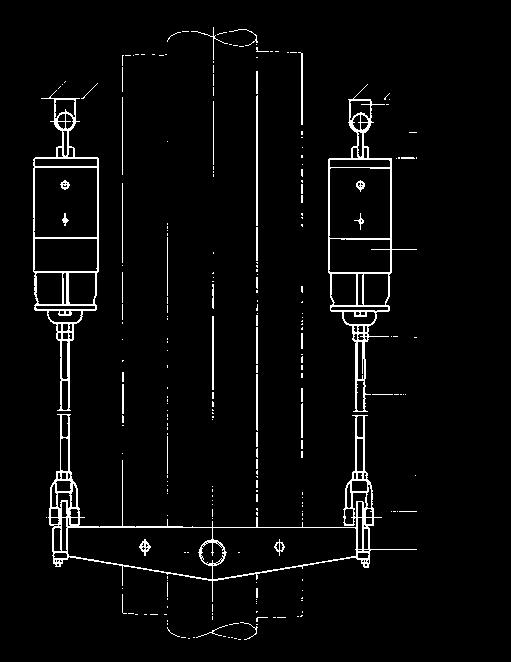
![E Constant supports Type 19 A B 1 Constant supports type 19 D3 17 to 19 93 17 Standard design, delivery from stock. H ØL 1 K M A 1 d 4 N B 1 min. load [kn] Order details: max.](/docs-images/78/76783190/images/23-2.jpg "load [kn] travel A A 1 B B 1 d 4 E H K M N type 19 D3 17 0.21 0.51 300 973 245 205 163 14.5 913 430 80 185 103 60 19 D1 27 0.21 0.72 75 610 245 205 163 14.5 490 234 80 185 103 36 19 D2 27 0.21 0.72 150 664 245 205 163 14.")


23 E Constant supports Type 19 A B 1 Constant supports type 19 D3 17 to Standard design, delivery from stock. H ØL 1 K M A 1 d 4 N B 1 min. load [kn] Order details: max. load [kn] travel A A 1 B B 1 d 4 E H K M N type 19 D D D D constant support type , marking:, calibration load: kn, travel: mm up/down, blocking position (as required): mm weight [kg] Load plate with integrated slide plate. This must be considered in the selection of clamp bases. Dimension E in blocking position right at top in other blocking positions E shortens accordingly and allows adjustment of + 60mm. Type is fitted with a load plate with PTFE slide plate as standard. If needed, this type can also be supplied with a high temperature slide plate, type (see table below). Under certain circumstances the support bracket with the height K can be dispensed with. It should however be ensured that the load adjustment screws are accessible. type 19* with slide plate up to 180 C up to 350 C ØL 1 19 D D * friction value of the slide plates see table p Max. permissible stresses: Emergency (HZ) at 80 C = calibration load x 1.33 Faulted condition (HS) at 150 C = calibration load x Max. blocking load at 80 C = calibration load x


 at 150 C = Calibration load x 1.66 Max. blocking load at 80 C = Calibration load x 1.5. Order details: angulating constant support type 19.")
![... marking: calibration load: kn travel: mm up/down blocking position (as required): mm min. load [kn] max. load [kn] travel A A 1 B B 1 d 3 E J H SW U type 19 D3 37 0.21 0.](/docs-images/78/76783190/images/24-4.jpg "51 300 973 245 205 163 10 903 45 430 27 23 58 19 D1 47 0.21 0.72 75 610 245 205 163 10 480 45 234 27 23 35 19 D2 47 0.21 0.72 150 664 245 205 163 10 590 45 270 27 23 40 19 D3 47 0.37 0.")
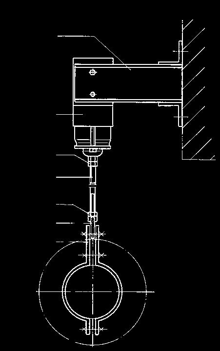
24 Angulating constant supports Type 19 Angulating constant supports type 19 D3 37 to Standard design, delivery from stock. E J A SW B For large horizontal displacements in the pipe systems the constant supports can be fitted with ball bushing joints. U d 3 A 1 H B 1 The ball bushing joints for the connection are designed to fit weld-on bracket type 35. Dimension E on blocking position right at top, in other blocking positions E shortens accordingly and allows adjustment of +200mm. Connection possibilities: See bolt diameter of weld-on brackets type 35 or dynamic clamps (Product Group 3). Max. permissible stresses: Emergency (HZ) at 80 C = Calibration load x 1.33 Faulted condition (HS) at 150 C = Calibration load x 1.66 Max. blocking load at 80 C = Calibration load x 1.5. Order details: angulating constant support type marking: calibration load: kn travel: mm up/down blocking position (as required): mm min. load [kn] max. load [kn] travel A A 1 B B 1 d 3 E J H SW U type 19 D D D D weight [kg] 1.21
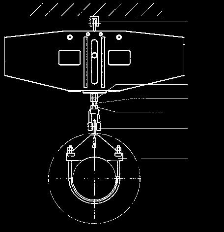
![Constant hanger trapezes Type 79 B L R 1 Ø d 3 A s U E B 1 min. load [kn] max. load [kn] travel L max A B d 3 E R s U B 1 weight for L=1000 per 100mm type [kg] [kg] 79 D3 17 0.42 1.](/docs-images/78/76783190/images/25-0.jpg "02 300 1700 973 205 17 569 25 10 80 140 121 1.7 79 D1 27 0.42 1.44 75 1700 610 205 17 372 25 10 80 140 79 1.7 79 D2 27 0.42 1.44 150 1700 664 205 17 409 25 10 80 140 87 1.7 79 D3 27 0.74 1.")


25 Constant hanger trapezes Type 79 B L R 1 Ø d 3 A s U E B 1 min. load [kn] max. load [kn] travel L max A B d 3 E R s U B 1 weight for L=1000 per 100mm type [kg] [kg] 79 D D D D Constant hanger trapezes type 79 D3 17 to Dimension E right at top in blocking position, for other blocking positions, dim. E lengthens accordingly. The L max dimensions can be lengthened to 2400mm, on reduction of the permissible center load by 5% per 100mm extension. When selecting the constant hanger trapeze the weight of the U-profiles and the clamp base weight must be added to the operating load. Max. permissible loads: Emergency (HZ) at 80 C = Calibration load x 1.33 Faulted condition (HS) at 150 C = Calibration load x 1.66 Max. blocking load at 80 C = Calibration load x 1.5 Order details: trapeze type L = mm marking: calibration load: kn of the support point trave: mm up/down blocking position (as required): mm 1.22


: mm type A max B C D E G L max X total weight [kg] L=1000 weight change [kg/m]")
26 Constant hanger trapezes Type 79 Constant hanger trapezes types 79 D2 15 to This design of trapeze is used if the standard design type does not fit due to extremely restricted installation space. The trapezes are supplied bolted ex works. Z A L G D B X E C X = min. engagement depth + 300mm engagement possibility. Dimension L and dimension Z are to be stated when ordering. Dimension E and dimension C 0mm in blocking position, in other blocking positions E and C lengthen accordingly. When selecting the constant hanger trapeze its total weight and the clamp base weight must be added to the operating load. The L max dimensions can be lengthened to 2400mm on load reduction by 5% per 100mm extension. Order details: trapeze type L = mm Z = mm marking: calibration load: kn of the support point travel: mm up/down blocking position (as required): mm type A max B C D E G L max X total weight [kg] L=1000 weight change [kg/m] 79 D D
![Heavy duty constant supports Type 16 1 A L B D C Heavy duty constant support types 16 82 29 to 16 93 49 K E H P T O S F M A 1 N Z B 1 33 type A A 1 B B 1 C D E E F H K L M N O P S T Z weight [kg] 16](/docs-images/78/76783190/images/27-1.jpg "82 29 860 640 635 580 500 555 1120 1132 120 585 300 200 490 300 50 330 15 15 300 635 16 83 29 990 640 635 580 500 555 1855 1867 120 715 755 200 490 300 215 340 15 15 300 920 16 92 29 910 740 695 630")


.")
27 Heavy duty constant supports Type 16 1 A L B D C Heavy duty constant support types to K E H P T O S F M A 1 N Z B 1 33 type A A 1 B B 1 C D E E F H K L M N O P S T Z weight [kg] Dimension E in blocking position right at top in other blocking positions E shortens accordingly and allows for adjustment of + 60mm. Dimension E for constant supports according to E, which are additionally fitted with a slide plate (friction value of the slide plates see p. 7.11). Type 16 is supplied with a corrosionprotected load plate as standard. When using a slide plate up to 180 C operating temperature, the type number in the 6th digit is to be replaced by a 7 (e.g ), or up to 350 C by a 6 (e.g ). E Load plate with integrated slide plate Order details: constant support type marking: calibration load: kn travel: mm up/down blocking position (as required): mm slide plate (as required): 1.24


 spring relaxation pipe statics that are not always readily determinable practical deviations from the")
28 Servohangers Type 17 Under certain conditions, pipe systems or other components are restricted in their thermal displacement through friction or other influences, despite the use of spring and constant hangers or constant supports. In such cases servohangers can actively overcome the restriction. Application In standard cases, the weight of the pipe systems is practically in equilibrium with the calibration load of the constant hangers and constant supports. The sum of the deviations occurring and the additional stresses in the piping due to this then remain within the permissible harmless range. In certain cases, the sum of the deviations occurring can also exceed a permissible level and considerably reduce the life of the piping systems or their connections (in the creep strength range) in the form of additional secondary stresses. Deviations can arise through: wall thickness tolerances of the piping, if these are not weighed extra and the weight differences taken into account insulation weights not determinable in advance mechanical friction and production tolerances for constant hangers (permissible +/ 5%) spring relaxation pipe statics that are not always readily determinable practical deviations from the theoretically planned load distribution A combination of deviations can cumulatively reach significant levels. These deviations have a particularly negative effect in flexible, soft pipe systems. Vertical expansion can be obstructed or even completely suppressed here, even with relatively slight individual deviations. Apart from the additional loads caused, impermissible sagging can result, due to spring hyste resis in the pressure-stressed system, with a reversed incline. In addition to possible creep rupture, in the event of an incorrectly positioned incline, dangerous water hammer can occur. In such cases it would be advisable to supplement the passively reacting constant hangers with the active LISEGA servohangers. Typical cases of application for LISEGA servohangers boiler center boiler center turbine turbine original cold position hot position new cold position without servohangers (diagram on left) the pipe system remains in the hot position with servohangers (diagram on right) the pipe system shifts to its specified positions 1.25

 / actual (travel) deviations a tolerance range can be set. If the deviation is outside these values, the control switches off automatically.")
 to 9 (F N 100kN) with travel ranges 2 (150mm) and 3 (300mm) are considered standard. For other cases, special designs can be supplied.")

29 Through use of the hydraulic servo support the pipe system can now be repositioned to the specified elevation. Design and mode of operation The type 11 constant hanger forms the basis for the servohanger. To overcome load differences it is additionally fitted with an auxiliary hydraulic device that can exert an active supplementary force in both directions (servo support). For theoretical (temp.) / actual (travel) deviations a tolerance range can be set. If the deviation is outside these values, the control switches off automatically. Manual switch-off For any maintenance work required on the system or the boiler, the servo support can be switched on or off manually. Design sizes Load Groups 5 (F N 20kN) to 9 (F N 100kN) with travel ranges 2 (150mm) and 3 (300mm) are considered standard. For other cases, special designs can be supplied. Operating instructions Installation and commissioning instructions, as well as servicing recommendations, are included in the scope of supply. Servohanger switch cabinet 1 For this, see also selection table constant hangers, pp and = travel range 2 3 = travel range 3 In standard cases, the temperature of the pipe system to be supported is used as a control parameter. The temperature in each case is transformed electronically into the corresponding travel position. In the theoretical / actual comparison procedure, the control ensures a regulated approach to the actual vertical elevation position. servohanger type nom. load FN [kn] set load [kn] load-dependent travel travel range 2 travel range 3 [mm] [mm] supplementary servo power [kn] Electrohydraulic control The hydraulic unit and the control are located separately from each other in a separate switch cabinet situated near the servohanger (max. distance 16m). The hydraulic pistons for control of the movement are located in the load tube of the constant hanger. Safety switch The electrohydraulic control is so designed that in the event of an operational breakdown (e.g. power loss) only the servo support is lost, but the unit will continue to function effectively as a constant hanger. hydr. control electr. control Function chart 1.26
 travel scale blocking strip indicator for calibration load load scale load adjustment")


30 Installation and operating instructions Types 11, 12-14, 18, 19 stop guide bolt name plate red marking for hot position retaining screw with washer for stop (after deblocking) travel scale blocking strip indicator for calibration load load scale load adjustment screw load tube inspection hole for min. engagement depth lock nut 1 Transport and storage During transport, care must be taken that connecting threads, stops and load adjustment bolts are not damaged. When storing in the open air, the supports must be protected from dirt and water. 2 Delivery condition If not otherwise agreed, LISEGA constant hangers are set to the desired cold load position Constant hanger type 11 (installation condition) and blocked. The adjustment values can be read off the load and travel scale as well as the name plate. On the travel scale the theoretical hot position is marked with a red sticker and the theoretical cold position with a white one. The order load set at the delivery inspection is permanently marked on the load scale with an X. Low profile constant hanger type 18 adjustment spindle Constant support type 19 support brackets ball bushing Travel scale with cold/warm marking adjustment spindle Coupled constant hanger type Angulating constant support type 19 ball bushing Load scale with indicator 1.27
 type serial number LISEGA order number calibration load inspector travel ident.")

 The upper connection is designed as a yoke plate.")
 These constant hangers for all load sizes can be directly seated.")
31 type 79 traverse type 71 support bearing type 11 constant hanger type 66 tie rod threaded clevis with pin type 60 eye nut stud bolt 1 X Name plate with stamped operating data Stamped on the plate are: Min. engagement depth X of upper connection (see selection table type 11, p. 1.15) type serial number LISEGA order number calibration load inspector travel ident. number steel construction onsite (bolted or welded) Connections type 11 C (single cell hangers) The upper connection is designed as an inner thread with limited engagement depth. The lower connection is designed as a spherical lock nut pivotable in all directions by min. 4. The connection threads are greased and sealed with plastic caps. When connecting to the connecting rods, care must be taken that the lower rod is screwed into the lock nut at least to the inspection hole. A further engagement depth of at least 300mm is available. Connections type (heavy duty) The upper connection is designed as a yoke plate. The lower connection is also designed as a yoke plate and fastened to the spherical lock nuts of the individual constant hanger cells, whereby pivoting of min. 4 is possible. The connection threads are greased and sealed with plastic caps. Constant hanger type 11 (seated) These constant hangers for all load sizes can be directly seated. They can also be supplied with serial support brackets type 71 which, depending on the order specifications, can be connected and bolted via precision-fit boreholes at works or on site. The base plates of the support brackets can be welded to the contact surface. On request, support brackets with slot holes for bolting can be supplied. Connections type 18 The upper connection is designed as a yoke plate and the lower one as a spherical lock nut, pivotable in all directions by min. 4. The connection threads are greased and sealed with plastic caps. Connections type 19 The upper connections of the constant supports are fitted either with a load plate or slide plate to reduce friction from lateral displacement, or with a ball-joint lug for angulating constant supports. The lower connections are therefore either a pedestal or a lug. During welding work at the pedestal the components inside constant supports must be protected. Inspection hole Min. engagement depth of connection rod in load tube 1.28
32 Transport lock type (heavy duty) Coupled constant hangers are supplied with a transport locking device (retaining rod, washer, retaining nut). B) The connecting rods are to be installed vertically for the purpose of better inspection. A con trolled angled position in operating condition is thereby permitted. At all events, uniform specifications for the whole installation should exist. cold position Rods vertical during plant operation warm position 1.29 warm position cold position Rods vertical in installation condition Transport lock type Retaining rod 2 Washer 3 Retaining nut The transport lock is loosened only on completion of hanger installation and at the same time as the removal of the blocking plates. For this, the retaining nut marked in red is removed at the lower end with a socket wrench. Both parts (retaining rod and nut) are to be stored in the same place as the stops. When making the force-fit connection, care must be taken that the lower yoke plate is screwed into the lock nuts at least up to the inspection hole. The installation dimension of the lower yoke plate can be lengthened with the lock nuts by 250mm or shortened by 70mm. 3 Installation of the constant hangers When installing, the specifications of the installation instructions for pipe systems must be followed. Special attention must thereby be paid to the desired installation position of the suspension rods throughout the whole support chain. There are two possibilities here: A) The connecting rods are to be installed at an angle according to the expected horizontal displacement in the pipe system. A perpendicular position is hereby anticipated in operating condition. The connecting rods and points are to be force-fitted. Type 11 C (single cell hanger) For installation of the constant hangers, transport lugs or other assembly devices can be screwed into the threaded holes on the sides. After deblocking of the hanger (see point 4) the stops are to be screwed on here for safe keeping. For constant hangers with support brackets type 71 the hangers are fitted with transport lugs instead of the upper connection these can also store the stops. Constant hangers types For installation of the hangers, the side openings of the upper yoke plate can be used for hooking on. For hangers with support brackets, the upper yoke plate is replaced by a transport lug. 4 Deblocking Requirements The correct deblocking of the constant hangers in accordance with the following instructions is crucial for the subsequent faultless functioning of the pipe systems. The stops are to be removed, as far as possible, immediately before commissioning. The stops must be removed as a matter of principle in a systematic way, one after the other, beginning at a fixed point or connection point. The whole system should be inspected beforehand according to point 3 of these installation instructions. Actual and theoretical condition When it has been ensured that all connections are firmly force-fitted, the suspended weight is completely taken up by the constant hangers or supports.

 to corresponding jamming of the blocking bolt in the lower or upper section of the blocking plate.")
33 If the weight load agrees with the calibration load and the piping system shows no sign of stress, then the planned equilibrium has been achieved. The blocking plates can be easily removed. In practice however, slight stresses in the piping systems and hence resulting load shifting can hardly be avoided. In the same way, the loads, which are usually determined theoretically, can show larger tolerances. As a result, the deviations can lead (according to under- or over-load) to corresponding jamming of the blocking bolt in the lower or upper section of the blocking plate. Procedure The blocking devices are removed when the guide bolt is free. The calibration load is made up of the old load and the extra weight of the hanger components suspended. If the guide bolt is lying at the top or the bottom, the load adjustment must be adapted before deblocking (see point 5, load correction): When removing the stops, care must be taken that only the outer lock ring is loosened. In cases of requirement, e.g. for revisions, the hangers or supports can be blocked again in any position. For this, the stops are placed on the guide bolts and secured. The devices are firmly screwed to the side of the constant hanger body in types 11 to 14. Load distribution Under no circumstances should the stops be removed by force! By loosening or tightening the connecting rods with a few turns of the lock nut in the case of constant hangers, or corresponding adjustment of the support tube for constant supports, stresses in the pipe system can be compensated for and the guide bolt is then free. The geometrical position of the pipe system must not be altered when balancing stresses! As later adjustment at one point can cause a renewed slight shift at another, the procedure must be repeated if necessary at different points. For clear control it is recommended that, as a matter of principle, the stops should only be removed when all the guide bolts are free. 5 Load correction type 11, Load correction is necessary if the calibration load(set at the LISEGA facility) deviates from the weight actually applied. In this case, with LISEGA hangers the calibration load can also be adjusted in the installed condition. 1 a) Bolt is free: Calibration load of the constant hangers agrees with the weight applied. Blocking plate can be removed. b) Bolt lies at bottom: Calibration load of constant hanger is smaller than weight applied. Loosen connecting rod or increase calibration load. c) Bolt lies on top: Calibration load of constant hanger is larger than weight applied. Tighten connecting rod or decrease calibration load. Blocked condition Dismantling of the outer lock ring and blocking device It should thereby be taken into account that for load increases the remaining travel is shorter. In most cases this is not critical, due to the travel and load reserves available. For safety reasons this should be checked with the catalog data. Any changes in the installation dimension caused by load corrections must be compensated for within the load chain. Procedure: 1) Loosen of both load adjustment screws. 1) Assembly of the outer lock ring Completed: deblocked condition 1.30


 Tighten the lock nuts of the load adjustment screws. Now deblocking can continue.")


 Turn adjusting screws equally on both sides until the guide bolt is free.")
34 2) 3) 2) Screw in or screw out alternately the two load adjustment screws, by a turn in each case. The base plate of the load tube and the lower edge of the constant hanger body must thereby remain parallel. The procedure is completed as soon as the guide bolt no longer lies at the top or the bottom of the stop. If, for constant hangers of higher load groups, the necessary adjustment forces are too big and manual adjustment is not possible, auxiliary devices must be used (see point 6, auxiliary devices). 3) Tighten the lock nuts of the load adjustment screws. Now deblocking can continue. Load correction types 18, 19 By way of the adjusting screws the length of the lever of the leverage arm is altered on the left and right respectively. On load adjustment the working travel remains unaltered. 6 Auxiliary devices Tightening or loosening of the connecting rods, as well as load calibration, can be performed manually on all hangers. For hangers in the higher load groups this work can require a great deal of effort due to the higher load calibration. To facilitate the work, an auxiliary device can be made available with which a hydraulic load take-up using a handpump can be effected. It is operated by LISEGA personnel. Installation device, used to relieve the adjustment screws Blocking device bolted to front side Procedure: 1) Unlock tab washer. 2) Turn adjusting screws equally on both sides until the guide bolt is free. 3) Secure adjusting screws against twisting by locking the tab washers. Installation device, used to relieve the blocking 7 Inspection and maintenance The flawless functioning of the constant hangers and supports can be checked in every operating situation by examining the position of the guide bolt. Under normal operating conditions, maintenance is not required. 1.31
Spring hangers, spring supports
 Spring hangers, spring supports 2 spring Spring hangers, supports PRODUCT 2 GROUP Spring hangers, spring supports Contents Page Field of application...2.1 Overview of spring hangers and spring supports...2.3
SPRING HANGERS, SPRING SUPPORTS PRODUCT GROUP
 SPRING HANGERS, SPRING SUPPORTS PRODUCT GROUP VARIABLE SPRING ELEMENTS CONTENTS PAGE 0 Spring hangers, spring supports, sway braces.1 Load table for spring hangers, spring supports and other spring elements.3
Pipe clamps, clamp bases, connecting parts
 Pipe clamps, clamp bases, pipe connecting parts 4 pipe Pipe clamps, clamp bases, connecting parts PRODUT 4 GROUP Pipe clamps, clamp bases, pipe connections ontents Page Field of application... 4.1 Product
Ball Rail Systems RE / The Drive & Control Company
 Ball Rail Systems RE 82 202/2002-12 The Drive & Control Company Rexroth Linear Motion Technology Ball Rail Systems Roller Rail Systems Standard Ball Rail Systems Super Ball Rail Systems Ball Rail Systems
1 Variable spring supports Design Instructions
 Design Instructions 1.1 Application Rigid supporting structures are not capable to accommodate vertical displacement or large horizontal forced travels of piping. This nodes should be supported by spring
Precision Modules PSK
 Precision Modules PSK The Drive & Control Company Rexroth Linear Motion Technology Ball Rail Systems Roller Rail Systems Standard Ball Rail Systems Super Ball Rail Systems Ball Rail Systems with Aluminum
STRUCTURAL ATTACHMENT ELEMENTS
 STRUCTURAL ATTACHMENT ELEMENTS 7 PRODUCT GROUP 7 STRUCTURAL ATTACHMENTS, TRAPEZES CONTENTS PAGE 0 Structural attachments, trapezes 7.1 Weld-on clevis type 73 7.2 Weld-on eye plate type 75 7.2 Weld-on
Technical specifications
 Technical specifications 0 Technical specifications Product 0 group Technical specifications Contents Page 1. Standard Supports, requirements and definition...0.1 2. LISEGA Standard Supports...0.1 3.
Precision Modules PSK
 Precision Modules PSK 2 Bosch Rexroth AG Precision Modules PSK R999000500 (2015-12) Identification system for short product names Short product name Example:: P S K - 050 - N N - 1 System = Precision Module
Precision Modules PSK. The Drive & Control Company
 Precision Modules PSK The Drive & Control Company 2 Bosch Rexroth Coporation Precision Modules PSK R310A 2414 (2008.07) Linear Motion and Assembly Technologies Ball Rail Systems Roller Rail Systems Linear
Compact Modules. with ball screw drive and toothed belt drive R310EN 2602 ( ) The Drive & Control Company
 The Drive & Control Company") with ball screw drive and toothed belt drive R310EN 2602 (2007.02) The Drive & Control Company Bosch Rexroth AG Linear Motion and Assembly Technologies Ball Rail Systems Roller Rail Systems Linear Bushings
with ball screw drive and toothed belt drive R310EN 2602 (2007.02) The Drive & Control Company Bosch Rexroth AG Linear Motion and Assembly Technologies Ball Rail Systems Roller Rail Systems Linear Bushings
Operating Instructions. Parallel shaft cam gear
 Operating Instructions Parallel shaft cam gear Type : Serial No. : C O N T E N T S 1. General 1.1 Validity 1.2 Safety instructions 1.3 Shipment 1.4 Transport Regulations 1.5 Weights of gear types 2. Instructions
Shaft-Hub-Connections
 Stand: 14.01.2010 Shaft-Hub-Connections Shrink Discs Cone Clamping Elements Star Discs 36 Edition 2012/2013 RINGSPANN Eingetragenes Warenzeichen der RINGSPANN GmbH, Bad Homburg Table of Contents Introduction
Translation of the Original operating instructions Lifting device Z 70 /...
 Translation of the Original operating instructions Lifting device Z 70 /... Content 1. Lifting device / Correct use according to regulations 2. Basic principles 3. General information 4. Special remarks
Rodless Pneumatic Cylinders Series OSP-P
 Rodless Pneumatic Cylinders Series OSP-P System Concepts & Components... 2-5 Technical Data... 7-9 Dimensions... 10-15 Active rakes... 16-19 Accessories (Mounts & Supports)... 20-29 Ordering Information...30
RoaDyn S635 System 2000
 Force RoaDyn S635 System 2000 Wheel Force Sensor for Heavy PassCars and High Performance Sports Cars Wheel force sensor for measuring three forces and three moments on a rotating wheel; a major constituent
Load Cell for Manually Operated Presses Model 8451
 w Technical Product Information Load Cell for Manually Operated Presses 1. Introduction... 2 2. Preparing for use... 2 2.1 Unpacking... 2 2.2 Using the instrument for the first time... 2 2.3 Grounding
RE / STAR Tolerance Rings STAR Ball Knobs, Knob and Lever Type Handles
 RE 2 970/.99 STAR Tolerance Rings STAR Ball Knobs, Knob and Lever Type Handles STAR Tolerance Rings Product Overview Tolerance rings are made of hard, embossed spring steel strip and belong to the class
ORDERING: Specify size, figure number, description, nominal pipe size or special O.D. and C-to-C dimension. C - C LOAD lb.
 Fig. 2110 www.pipingtech.com/fig2110 Sway Strut with 4 of Adjustment Engineered spring supports option 1 option 2 ORDERING: Specify size, figure number, description, nominal pipe size or special O.D. and
Linear Shaft Motors in Parallel Applications
 Linear Shaft Motors in Parallel Applications Nippon Pulse s Linear Shaft Motor (LSM) has been successfully used in parallel motor applications. Parallel applications are ones in which there are two or
Bearing preload. Preload considerations
 Bearing preload There may be some applications where the bearing arrangement needs to be preloaded i.e. requires a negative operating clearance. In applications such as machine tool spindles, automotive
Operating Instructions. Globoidal cam gear
 Operating Instructions Globoidal cam gear Type : Serial No. : TABLE OF CONTENTS 1. General 1.1 Validity 1.2 Safety instructions 1.3 Shipment 1.4 Transport Regulations 1.5 Weights of gear types 2. Instructions
...our linkages, your solution. Rod Ends
 ...our linkages, your solution Technical Information Introduction All of our rod ends incorporate either a plain spherical bearing, ball bearing, or roller bearing. Below is an overview of each type. Plain
V SWISS MADE LINEAR TECHNOLOGY
 Compact units Excerpt from main catalogue SWISS MADE LINEAR TECHNOLOGY V 11-15 Line Tech compact units Table of contents Product overview 106 107 Design fundamentals / Lubrication / Maintenance 108 Profile
Manual Monorail Track System
 www.wampfler.com Page 1/57 www.wampfler.com Page 2/57 1 General...6 1.1 Use of standard elements...7 1.2 Determination of the permissible support centers...9 1.3 Questionnaire...11 1.4 Project notes...12
Miniature Ball Rail Systems
 R310EN 2210 (2004.06) The Drive & Control Company 2 Bosch Rexroth AG Linear Motion and Assembly Technologies Miniature-BRS R310EN 2210 (2004.06) Linear Motion Systems Ball Rail System Standard Ball Rail
Standard with cone bushing. Backlash-free Safety Clutch
 EAS -Compact ratchetting clutch/synchronous clutch The Backlash-free Safety Clutch for Standard with cone bushing Packaging Machinery Machine Tools Paper Machinery Indexing Drives Servo Motors EAS -NC
Series 430 Type 3430 Pneumatic Indicating Controller for Temperature with Capillary Sensor Type 3432 Controller Station Type 3436 Transmitter Module
 Series 430 Type 3430 Pneumatic Indicating Controller for Temperature with Capillary Sensor Type 3432 Controller Station Type 3436 Transmitter Module Application Temperature controller for process engineering
Is Low Friction Efficient?
 Is Low Friction Efficient? Assessment of Bearing Concepts During the Design Phase Dipl.-Wirtsch.-Ing. Mark Dudziak; Schaeffler Trading (Shanghai) Co. Ltd., Shanghai, China Dipl.-Ing. (TH) Andreas Krome,
INDUSTRIAL PIPE SUPPORTS CATALOGUE
 INDUSTRIAL PIPE SUPPORTS CATALOGUE DATE PUBLISHED: 1/06/2017 BINDER GROUP INDUSTRIAL PIPE SUPPORT CATALOGUE TABLE OF CONTENTS 1. INTRODUCTION... 4 2. QUALITY MANAGEMENT CERTIFICATE... 5 3. PIPE SUPPORT
RIGIFLEX -N RADEX -N. Steel laminae coupling. Steel laminae coupling. You will find continuously updated data in our online catalogue at
 117 Table of contents 117 Coupling selection steel laminae coupling 119 Description of coupling 121 General information 122 Types and applications 123 Technical data 124 Standard types 126 Special types
Contents. Page. 1. Product description. 2. The AXC line of linear axes. 3. AXLT line of linear tables. AXC and AXS product overview...
 SNR Industry Contents Page 3 1. Product description AXC and AXS product overview... 6-8 Dynamic load ratings of the linear motion systems... 9 Compact modules... 10-11 Linear tables... 12 Telescopic axes...
Assemblies for Parallel Kinematics. Frank Dürschmied. INA reprint from Werkstatt und Betrieb Vol. No. 5, May 1999 Carl Hanser Verlag, München
 Assemblies for Parallel Kinematics Frank Dürschmied INA reprint from Werkstatt und Betrieb Vol. No. 5, May 1999 Carl Hanser Verlag, München Assemblies for Parallel Kinematics Frank Dürschmied Joints and
Chain and Belt Tensioning Systems
 Chain and Belt Tensioning Systems Chain and Belt Tensioning Systems 121 TENSIONING SYSTEMS TABLE OF CONTENTS Introduction 123 Function, Principles, Handling 124 Optical Control Displays 125 Chain and Belt
MECHANICAL Forging PRESSES WITH KNUCKLE-JOINT
 MECHANICAL Forging PRESSES WITH KNUCKLE-JOINT MML / MSL. Mechanical Forging Presses with knuckle-joint. From process development and cost-effective line concepts to full production lines. MECHANICAL Forging
TELESCOPIC RAIL HEAVY
 TELESCOPIC RAIL HEAVY Every care has been taken to ensure the accuracy of the information contained in this catalogue, but no liability can be accepted for any errors or omissions. We reserve the right
NSK Linear Guides. Roller Guide RA Series. Extended series
 NSK Linear Guides A roller guide series employing advanced analysis technology offers super-high load capacity and rigidity. The RA series includes a complete lineup to handle a wide range of applications.
SCHMIDT ServoPress. Unmatched Precision and Flexibility
 SCHMIDT ServoPress Unmatched Precision and Flexibility An economic and high quality assembly is the key to the success of your product. The aim is to join together precise assemblies from low-cost individual
S840, S845, S846 Series Single-break changeover, NC or NO contacts, positive opening operation and wiping action Catalogue D40.en
 Snap-action switches S80, S85, S86 Series Single-break changeover, NC or NO contacts, positive opening operation and wiping action Catalogue D0.en Snap-action switches, S80, S85, S86 Series Single-break
RIGGING HARDWARE SOLUTIONS for WIRE AND ROD SYSTEMS
 RIGGING HARDWARE SOLUTIONS for WIRE AND ROD SYSTEMS YSC QA108 THE STA-LOK STORY The new Sta-Lok range bears clear traces of our marine heritage. When we started manufacturing Sta-Lok rigging hardware in
Product overview. 10 Bosch Rexroth Corporation Compact Modules R310A 2602 ( ) Compact Modules CKK. Compact Modules with ball screw drive (CKK)
 Compact Modules CKK. Compact Modules with ball screw drive (CKK)") 10 Bosch Rexroth Corporation R310A 2602 (2008.09) CKK with ball screw drive (CKK) Product overview are precision, ready-to-install linear motion systems characterized by their high performance and compact
10 Bosch Rexroth Corporation R310A 2602 (2008.09) CKK with ball screw drive (CKK) Product overview are precision, ready-to-install linear motion systems characterized by their high performance and compact
Reaction Torque Sensor
 Force 1 1 N m up to 1 000 1 000 N m Type 9329A 9389A These easy to install piezoelectric reaction torque sensors are particularly suitable for measuring rapidly changing torques at non-rotating shafts.
Linear Motion Technology Handbook. The Drive & Control Company
 Linear Motion Technology Handbook The Drive & Control Company 1-2 Bosch Rexroth AG Linear Motion Technology Handbook R310EN 2017 (2006.07) Linear Motion and Assembly Technologies www.boschrexroth.com/brl
4/3-way high response directional control valve pilot operated with electrical feedback and integrated electronics (OBE)
") 4/3-way high response directional control valve pilot operated with electrical feedback and integrated electronics (OE) ype 4WRDE Nominal size to 35 Component series 5X Maximum operating pressure 3 bar
4/3-way high response directional control valve pilot operated with electrical feedback and integrated electronics (OE) ype 4WRDE Nominal size to 35 Component series 5X Maximum operating pressure 3 bar
SCHMIDT ManualPress 300 Series
 Manual Presses with Process Monitoring Process reliability, force/stroke monitoring of the joining process and EN ISO-compatible documentation of the results are becoming the major factors for small and
Components for parallel kinematics
 Components for parallel kinematics Series GLK, GLK 2, GLK 3 and GLAE Parallel kinematic components consist of a number of parallel, longitudinally adjustable mechanical struts that are arranged between
Vibration damping precision couplings
 Vibration damping precision couplings In light of the advantages of elasticity, strength, resilience, and damping effects, elastomer materials are now being used in most areas of mechanical engineering.
Courtesy of CMA/Flodyne/Hydradyne Motion Control Hydraulic Pneumatic Electrical Mechanical (800)
") 01_1 Miniature st Headline_36 Ball Rail pt/14.4 Systems mm second line 2 Linear Motion and Assembly Technologies Miniature Ball Rail Systems Ball Rail Systems Roller Rail Systems Linear Bushings and Shafts
01_1 Miniature st Headline_36 Ball Rail pt/14.4 Systems mm second line 2 Linear Motion and Assembly Technologies Miniature Ball Rail Systems Ball Rail Systems Roller Rail Systems Linear Bushings and Shafts
Accessories smart additions for efficiency and intelligent performance
 smart additions for efficiency and intelligent performance Metal bellows couplings Perfectionists you can count on Metal bellows couplings are designed for the highest requirements in servo drive technology.
Model R. q Fig. 81-H: Standard Type: q A, q B, q C, q D, q E, q F. q Fig. C-81-H: Corrosion Resistant CONSTANT SUPPORTS.
 OSA SUPPORS odel R q Fig. 81-: Standard : q A, q, q, q, q, q F q Fig. -81-: orrosion Resistant : q A, q, q, q, q, q F onstant Support Finish: Standard finish; painted with semi gloss primer. orrosion resistant;
Die changing technique
 Die changing Die changing 8 Contents Product group 8 Roller bar, hydraulically lifted for heavy loads (400 bar), lifting of the complete roller bar for medium loads (120 bar), lifting of individual rollers
series Linear guideways CG-serie 3.3 CG series
 series CG-serie 3.3 CG series 3.3.1 Properties of the linear guideways, series CG The HIWIN linear guideways of the CG series with O-arrangement of the ball tracks guarantee high torque loading capacity,
EMC-HD. C 01_2 Subheadline_15pt/7.2mm
 C Electromechanical 01_1 Headline_36pt/14.4mm Cylinder EMC-HD C 01_2 Subheadline_15pt/7.2mm 2 Elektromechanischer Zylinder EMC-HD Short product name Example: EMC 085 HD 1 System = ElectroMechanical Cylinder
R310EN 2211 ( ) The Drive & Control Company
 The Drive & Control Company") eline Ball Rail Systems R310EN 2211 (2006.04) The Drive & Control Company Bosch Rexroth AG Linear Motion and Assembly Technologies Ball Rail Systems Roller Rail Systems Linear Bushings and Shafts Ball
eline Ball Rail Systems R310EN 2211 (2006.04) The Drive & Control Company Bosch Rexroth AG Linear Motion and Assembly Technologies Ball Rail Systems Roller Rail Systems Linear Bushings and Shafts Ball
Tension and Compression Load Cell Model 8435
 Technical Product Information w Tension and Compression Load Cell 1. Introduction... 2 2. Preparing for use... 2 2.1 Unpacking... 2 2.2 Using the instrument for the first time... 2 2.3 Grounding and potential
NEW. Cone Clamping Elements Trantorque Keyless Locking Devices for very small diameters from 3 mm. E03.050e
 Cone Clamping Elements Trantorque Keyless Locking Devices for very small diameters from 3 mm NEW E03.050e Backlash free positioning Excellent concentricity Quick mounting by central clamping nut Issue
Guide units. For toolmaking, fixture manufacturing and machine engineering
 Guide units For toolmaking, fixture manufacturing and machine engineering Guide units in compliance with DIN, ISO and STEINEL standards or according to your specifications Guide pillars Guide and pillar
OPTIMASS 3000 Technical Datasheet
 OPTIMASS 3000 Technical Datasheet Sensor for mass flow First choice for low flow applications Certified secondary pressure containment A common footprint for all three sizes, in Hastelloy or Stainless
Linear Drive with Ball Screw Drive Series OSP-E..SB
 Linear Drive with Ball Screw Drive Series OSP-E..SB Contents Description Data Sheet No. Page Overview 1.30.001E 47-50 Technical Data 1.30.002E-1 to 5 51-55 Dimensions 1.30.002E-6, -7 56-57 Order instructions
ORIGA Pneumatic Linear Drives OSP-L
 ORIGA Pneumatic Linear Drives OSP-L Very long lifetime and lowest leakage A NEW Modular Linear Drive System With this second generation linear drive Parker Origa offers design engineers complete flexibility.
Rotary-Linear Actuator HSE4 Hydraulic / 100 Bar
 Rotary-Linear Actuator HSE4 Hydraulic / 100 Bar 4 Function and features K A1 G1 B1 G2 KM Y B2 RE A2 Z S2 A S1 W B KS [ Operation ] [ Operating pressure ] The Eckart rotary-linear actuator HSE4 is a combination
Installation and Operational Instructions for EAS -Compact overload clutch, Type 49_. 4._ Sizes 4 and 5
 Please read these Operational Instructions carefully and follow them accordingly! Ignoring these Instructions may lead to malfunctions or to clutch failure, resulting in damage to other parts. Contents:
1. Product overview Basic-Line-Module AXN Product description Basic-Line-Module AXN 4-5. Guide system Roller guide 6 Drive system Gear belt 7
 Directory Page 1. Product overview Basic-Line-Module AXN 3 2. Product description Basic-Line-Module AXN 4-5 Guide system Roller guide 6 Drive system Gear belt 7 3. Basic-Line-Modul AXN 45-Z 8-9 AXN 65-Z
STAR Ball Rail Tables TKK
 before operating X4 X8 X3 X1 X2 S1 S2 12 4 13 5 14 6 15 7 16 8 1 2 3 9 10 11 1 2 3 4 5 6 8.8 S3 X30 Indramat DANGER! AC-CONTROLLER High voltage Danger of electrical shock Do not touch electrical connnections
L Standard Parts for Mould Making
 A Die Sets B Precision Ground Plates and Flat Bars C Lifting and Clamping Devices Shanks, Lifter Studs and Lifting Hooks, Eyebolts Clamping Claws, Screws and Bolts D Guide Elements E Ground Precision Components
Mounting and Operating Instructions EB 3913 EN. Electropneumatic Converters i/p Converter Type
 Electropneumatic Converters i/p Converter Type 3913-0001 Fig. 1 Type 3913-0001 Electropneumatic Converter with pressure gauge and bracket Mounting and Operating Instructions EB 3913 EN Edition August 2011
Cage Bearing Concept for Large-scale Gear Systems
 Cage Bearing Concept for Large-scale Gear Systems Roland Lippert and Bruno Scherb INA reprint from Der Konstrukteur Vol. No. S 4, April 1999 Verlag für Technik und Wirtschaft, Mainz Cage Bearing Concept
Electropneumatic Converters i/p Converters Type 6111 Mounting and Operating Instructions EB 6111 EN
 Electropneumatic Converters i/p Converters Type 6111 Fig. 1 Type 6111 in standard version Fig. Type 6111 mounted on a supply air manifold Fig. 3 Type 6111 in field enclosure Mounting and Operating Instructions
Profile series I-40. System kit Profile series I-40
 Profile series I-40 System kit Profile series I-40 n n n a n n n R n a R 45 Profile series I-40 Contents 1 Technical data/profile machining F f Page 1 2 Page 1 3 Page 1 5 Page 1 8 Profiles Page 2 2 3000
LIGHTWEIGHT AND COMPACT. SERIES SL Nm. single-position multi-position. THE ultimate COUPLING from Nm
 LIGHTWEIGHT AND COMPACT L SAFETY COUPLINGS TOQLIGHT SEIES SL 5 700 Nm THE ultimate COUPLING from 5 700 Nm SEIES SL DESIGN / FEATUES Extremely lightweight construction Up to 60 % weight reduction in comparison
SCHMIDT ManualPress From 1.6 kn to 22 kn / 360 lbs. to 4,945 lbs.
 SCHMIDT ManualPress From 1.6 kn to 22 kn / 360 lbs. to 4,945 lbs. Efficient manufacturing requires appropriate means of production not always automation. In particular, with small production runs, manual
BoWex FLE-PA. BoWex FLE-PAC. KTR-N Sheet: Edition: EN 1 of BoWex FLE-PA / FLE-PAC Operating/Assembly instructions
 1 of 17 is a torsionally rigid flange coupling. It is able to compensate for shaft misalignment, for example caused by manufacturing inaccuracies, thermal expansion, etc. BoWex FLE-PA BoWex FLE-PAC Drawn:
Variable Valve Drive From the Concept to Series Approval
 Variable Valve Drive From the Concept to Series Approval New vehicles are subject to ever more stringent limits in consumption cycles and emissions. At the same time, requirements in terms of engine performance,
Servo-pneumatic drive solution for welding guns. Top quality welding!
 Servo-pneumatic drive solution for welding guns Sturdy and precise! Top quality welding! Highlights Extremely short cycle times High quality and outstanding reproducibility of the spot welds Excellent
PERFECTLY POSITIONED FOR ANY CHASSIS.
 SUSPENSION SPRINGS PERFECTLY POSITIONED FOR ANY CHASSIS. Egon von RUVILLE GmBH Billbrookdeich 112 22113 Hamburg Germany Tel.: +49 40 73344-0 Fax: +49 40 73344-199 info@ruville.de www.ruville.de NEW IN
Ball. Ball cage. Fig.1 Structure of Caged Ball LM Guide Actuator Model SKR
 Caged all LM Guide Actuator Model Inner block all screw shaft Grease nipple Outer rail all cage all Structure and Features Fig.1 Structure of Caged all LM Guide Actuator Model Caged all LM Guide Actuator
USING ACTIVE MAGNETIC BEARINGS FOR HIGH SPEED MACHINING CONDITIONS AND BENEFITS
 USING ACTIVE MAGNETIC BEARINGS FOR HIGH SPEED MACHINING CONDITIONS AND BENEFITS Jobst Görne, HTW Aalen, Deutschland, e-mail: jobst.goerne@htw-aalen.de Abstract: Active Magnetic Bearings offer high rotational
Rexroth Linear Motion Technology
 Linear Modules Robotic Erector System for Linear Modules RE 82 402/2003-10 The Drive & Control Company 1 RE 82 402/2003-10 Rexroth Linear Motion Technology Ball Rail Systems Roller Rail Systems Standard
CHAPTER THREE DC MOTOR OVERVIEW AND MATHEMATICAL MODEL
 CHAPTER THREE DC MOTOR OVERVIEW AND MATHEMATICAL MODEL 3.1 Introduction Almost every mechanical movement that we see around us is accomplished by an electric motor. Electric machines are a means of converting
Mounting and operating instructions EB 5801 EN. Electric Actuators Type 5801 (Rotary Actuator) Type 5802 (Linear Actuator)
 Type 5802 (Linear Actuator)") Electric Actuators Type 5801 (Rotary Actuator) Type 5802 (Linear Actuator) Linear Actuator with Type 3260 Control Valve Rotary actuator with lever system Linear actuator with Type 3321 (V2001) Control
Electric Actuators Type 5801 (Rotary Actuator) Type 5802 (Linear Actuator) Linear Actuator with Type 3260 Control Valve Rotary actuator with lever system Linear actuator with Type 3321 (V2001) Control
6.0 SPECIFICATIONS CONTENTS. Calibration. According to factory procedureeeeeeeeeeeeeee Accuracy*
 6.0 SPECIFICATIONS Calibration According to factory procedureeeeeeeeeeeeeee Accuracy* ± 1% full scale (FS) or ± 1 graduation on scale Scale diameter 41 mm Temperature range 45 to 115 F (10-45 C) Air humidity
Standard Supports 2020
 Standard Supports 2020 Standard Supports 2020 dition: September 2016 The LISG product program covers all components required for the implementation of modern concepts in the support of pipe systems. These
tensioning systems 107
 Tensioning systems 107 TENSIONING SYSTEMS TABLE OF CONTENTS Table of Contents 108 Introduction 109 Function, Principles, Handling 110 Optical Control Displays 111 Spann-Box Overview 112 113 Signs and Symbols
B Precision Ground Plates and Flat Bars. E Ground Precision Components. G Elastomer-Bars, -Sheets, -Sections
 A Die Sets B Precision Ground Plates and Flat Bars C Lifting and Clamping Devices Shanks, Lifter Studs and Lifting Hooks, Eyebolts Clamping Claws, Screws and Bolts D Guide Elements E Ground Precision Components
Proportional directional valve, pilot-operated, with integrated electronics (OBE)
") Proportional directional valve, pilot-operated, with integrated electronics (OBE) Type WFCE RE 943 Edition: 7- Replaces: 6- Size 6 5 Component series X Maximum operating pressure 4 bar Maximum flow 5 l/min
Proportional directional valve, pilot-operated, with integrated electronics (OBE) Type WFCE RE 943 Edition: 7- Replaces: 6- Size 6 5 Component series X Maximum operating pressure 4 bar Maximum flow 5 l/min
ENGINEERED TO MOVE. DA Series Electric Roller Screw Actuators with Integrated Motors
 ENGINEERED TO MOVE DA Series Electric Roller Screw Actuators with Integrated Motors ENGINEERED TO MOVE DA Series Electromechanical Actuators (EMA) The DA Series electromechanical actuators (EMAs) are equipped
Vickers 45. VMQ Series 30 Vane Pumps. Fixed Displacement, For Industrial and Mobile Applications (4.188)
") [ (4.188) 49,4 (1.94) /21,8 /.86) 174,7/172,3 (6.88/6.78) 332,9/33,5 (13.11/13.1) "M" is marked if metric port threads No marking if inch port threads AS-568-152 O-ring Vickers 45 65,3 (2.57) 13 (5.1 VMQ
[ (4.188) 49,4 (1.94) /21,8 /.86) 174,7/172,3 (6.88/6.78) 332,9/33,5 (13.11/13.1) "M" is marked if metric port threads No marking if inch port threads AS-568-152 O-ring Vickers 45 65,3 (2.57) 13 (5.1 VMQ
DM01. Battery Powered Precision Digital Gauge. Stainless Steel Sensor. class 0.05
 Battery Powered Stainless Steel Sensor class 0.05 Nominal pressure from 0 00 mbar up to 0... 00 bar Special characteristics modular sensor concept data logger graphic display stainless steel housing Ø
B kv T&D GAS INSULATED SWITCHGEAR
 GAS INSULATED SWITCHGEAR B 105 170 300 kv The increasing demand for electrical power in cities and industrial centers necessitates the installation of a compact and efficient distribution and transmission
Product overview. Joints. Circlips for ball seats DIN K0714. Quick plug couplings with radial offset compensation K0709. Page 837.
 Joints 825 Product overview Joints Quick plug couplings with radial offset compensation K0709 Quick plug couplings with radial offset compensation and screw-on flange K0710 Quick plug couplings with angular
6-speed manual gearbox 0A5
 Service Training Self-study programme 320 6-speed manual gearbox 0A5 Design and function S320_002 In addition to meeting increasing technical demands, modern cars also have to represent effective space
fsens Force Measurement
 Mobile Machine Control Solutions fsens Force Measurement Reliable Accurate Safe Strong and Accurate fsens. Force Sensors from Hirschmann MCS Benefits of the fsens Series: Reliable and exact measurement
Systems. Dynamic Test. Electrodynamic Vibration Test Systems
 Systems 100 - water 120 kn cooled Electrodynamic Vibration Test Systems SW3-10480APP (100KN) SW3-10LS3-550APP (100KN) SW3-10650APP (100KN) SW3-12480APP (120KN) SW3-12LS3-550APP (120KN) Dynamic Test Technical
MN Press Force Calibration Sensor
 Force Sensor for Measuring Large Compression Force Piezoelectric sensor for measuring quasistatic and dynamic compression forces in the meganewton range. This series of calibration sensors is designed
SUSPENSION 04 CLAMPS
 SUSPENSION CLAMPS 04 4 SUSPENSION CLAMPS 57 Contents General... 58 Suspension clamp trunnion type, forged,... 63 Suspension clamp trunnion type, forged, with bigger angle of deflection, for aluminium based
Variable-speed drive solutions: Less current, less noise, less costs.
 Variable-speed drive solutions: Less current, less noise, less costs. Variable-speed drives connect standard components from hydraulic and electric systems to form customized, intelligent and cost-efficient
KTR Torque Limiters Overload Protection Systems
 KT Torque Limiters Overload Protection Systems UFLEX - Friction Disk - Zero Backlash Ball Detent KT SI - Ball/oller Bearing Style KT SI Compact - Zero Backlash Ball Detent Catalog Contents (Metric) Page
SITRANS F flowmeters SITRANS F C MASSFLO MASS MC1. 4/146 Siemens FI Overview
 Overview MSS 2100 MC1 DN 50 to DN 150 (2 to 6 ) is suitable for accurate mass flow measurement for all kind of liquids and gases. The sensor offers superior performance in terms of flow accuracy, turn-down
ARI-ZETRIX ANSI. with worm gear. with electric rotary actuator Auma or Schiebel. with pneumatic actuator. with hydraulic actuator
 Process valve - Fig. 016 - Double flanged process valve with metallic sealing - Triple offset - Fig. 018 - Fully lugged process valve with metallic sealing - Triple offset - Fig. 019 - Butt weld ended
TORQLIGHT SAFETY COUPLINGS
 LIGHTWEIGHT AND COMPACT single-position TOQLIGHT SAFETY COUPLINGS SEIES SL 10 700 Nm THE ULTIMATE COUPLING FOM 10 700 Nm SEIES SL DESIGN / FEATUES Extremely lightweight construction Up to 60 % weight reduction