Spring hangers, spring supports
|
|
|
- Moses Cole
- 6 years ago
- Views:
Transcription
1 Spring hangers, spring supports 2 spring Spring hangers, supports PRODUCT 2 GROUP
2
3 Spring hangers, spring supports Contents Page Field of application Overview of spring hangers and spring supports Selection overview, spring components Selection tables Spring hangers type Heavy duty spring hangers type Spring hangers type Heavy duty spring hangers type Spring support type Heavy duty spring supports type Angulating spring supports type Spring hanger trapezes type Sway brace type Telescoping spring supports type Installation and operating instructions PRODUCT2 GROUP


4 Field of application To avoid constraints in the system, thermal expansion in high-temperature piping must not be restricted. The piping must therefore be supported in a correspondingly elastic manner. Spring components To balance slight vertical displacement in the pipe systems, spring components are used as supports. These components function on the basis of preset helical coil springs which exert a variable supporting load over the range of movement in accordance with their specified spring characteristics. Load variations resulting from this are limited through the stress analysis calculations, depending on the sensitivity of the piping. The relevant basis for the function of the spring components is specified in the current guidelines (see technical specifications p. 0.5). LISEGA spring hangers and supports A range of spring component designs are available for optimum adaptation to the various structural requirements. The ideal choice depends on the installation situation. Spring hangers and supports are as a rule calibrated in such a way that the spring force and pipe load are the same in the cold position (see p. 0.5). The corresponding hot load position results from the theoretical pipe displacement (travel) and the spring rate. The difference in force between hot and cold positions acts on the pipe system as a reaction force and is limited by the relevant design specifications. Further information can be found on p As standard practice, the permissible force deviation between cold position (blocking position) and hot position should not exceed 25 % in relation to the hot load. Moreover, as a rule constant hangers/supports are used that maintain a constant hanger/support force over the whole displacement range. Selection of spring hangers The reaction force depends on the spring rate (stiffness) of the respective coil springs. The change in force from cold to hot position results from the displacement. The greater the spring rate, the greater the change in load and accordingly the reaction force in the pipe system. For optimum selection of spring hangers and supports, LISEGA has divided the load ranges into 5 travel ranges. Details of their application can be found in the selection table (see pp. 2.5 and 2.6), in the installation and operating instructions (p. 2.19) and the technical specifications (p. 0.3). Load setting and blocking Spring hangers and supports are preset at the factory to the cold or blocking load and blocked in both directions of movement. This enables installation of the support in the designated installation space without time-consuming later adjustments. In addition, the supplementary loads arising through pickling, flushing or pressure testing are held by the blocking devices. cold and hot positions are shown on the travel scale by white and red marking respectively the blocking devices have continuously variable settings and can be applied again in any position 2.1

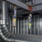
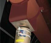
. 4 Fully adjustable blocking system. 5 On the spring hangers, the preset values are noted on the riveted name plate.")
5 2 Special advantages of LISEGA spring hangers axis of symmetry The user can profit from a wide range of special benefits with LISEGA spring hangers Significant savings are possible, particularly with regard to ancillary labor-intensive support costs such as planning, installation and operation Spring hanger type 21 1 No welding (types 20, 21, 27). 2 Fully galvanized surfaces. For heavy duty designs: coated surfaces. 3 The hot or cold position is marked on the travel scale (white and red arrow). 4 Fully adjustable blocking system. 5 On the spring hangers, the preset values are noted on the riveted name plate. 6 Special pre-relaxed springs with a CPP (cataphoretic painting process) finish prevent any significant loss in load capacity. 7 Integrated connecting elements. axis of symmetry 8 Variable connection possibilities within the load group selected and the possibility of later adjustment for load setting Spring hanger type 22 9 The theoretical hot position (operating position) is marked on the travel scale (red arrow). Five travel ranges from 0 to 400mm, load group C to load group 9 Three travel ranges from 0 to 200mm, load group 10 to load group 50. Load application free of moments by covering the load and symmetry axis. Favorable power-to-weight-ratios for reduced assembly weights. Modular system simplifies selection (load groups and travel ranges). Flexible installation configurations using standardized components. Secure connection of load chains through the load and connection compatibility of system components. 2.2


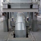
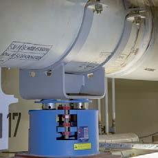
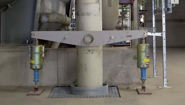
6 Overview of types Spring hangers and spring supports kN Heavy duty design kN Spring hanger type 21 Spring hanger type 25 Spring hanger type 21 This design is the most commonly used and is fitted with an upper connection for suspension. It is used where the surrounding structure offers a suitable connection point and sufficient installation space. The upper connections can be universally adapted to the existing conditions using standard components. Spring hanger type 25 This version is used especially if the permissible deflection of a support chain when using type 21 was exceeded or if, due to shortage of space, a type 21 spring hanger cannot be installed. The connection is made by a rod fed through the hanger. Spring hanger type 22 This design corresponds functionally to type 21 and is available for higher loads up to 400kN. Spring hanger type 26 This design corresponds functionally to the seated spring hanger type 25 and is available for higher loads up to 400kN. Spring support type 29 Spring support type 29 If the surrounding conditions do not permit suspensions, this design offers a suitable alternative as a support. For larger horizontal displacements of the support-bearing load and of steel/steel slide plate contact, under certain circumstances the functioning of the support can be adversely affected by any lateral forces generated. It is recommended to avoid this risk by using LISEGA slide plates. In this case the counter plate must have a stainless steel surface and if necessary be fitted with a twist restraint. Spring support type 28 This design corresponds functionally to spring support type 29 and is available for higher loads up to 400kN. Here too, LISEGA sliding components can be used as an option. Angulating spring support type 20 In contrast to the type 29 spring supports, lateral displacements can be absorbed practically free of friction forces by this design. This way, resulting forces in all planes, both in vertical as well as horizontal directions of movement, are almost completely eliminated. Angulating spring support type The angulating spring supports are fitted on one side with an adjustable load tube and a rotating ball bushing joint and on the other with a fixed ball bushing joint. The joints provide the appropriate connection to the type 35 weld-on brackets and the dynamic clamps in product group 3.
.")
, PTFE sliding materials (up to 180 C) or suitable material for higher temperatures are used.")
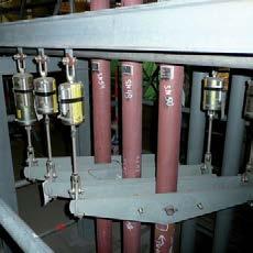
7 Sway braces type 27 These special components act in compression and tension directions and are used to stabilize the position of pipe systems and other plant equipment. The connection components correspond with those in product group 3 (dynamic components). With the LISEGA sway braces type 27 the following settings can be made: load pre-tensioning installation dimensions free stroke Add-on components Slide plate for spring supports type 29/28 To reduce friction between the load plate and mating component (e.g. clamp base), PTFE sliding materials (up to 180 C) or suitable material for higher temperatures are used. The counter component should in this case have a stainless steel sliding surface. The selection of slide plates can be found on p Spring support type (telescopic) 2 Spring hanger trapezes type 79 These commonly used components combine the advantages of the spring hanger with the easy-to-install, weld-free plug-in trapezes. For restricted spaces the spring hanger trapezes can be supplied as special welded designs. Extension for spring support type 29 To bridge larger installation heights, adapted extensions can be ordered (see p. 2.11). Sway brace type 27 angled arrangement Base plate for spring hanger type 25 If required, type 25 can be supplied with the base plate type 27 for bolting or welding. A selection can be found on p Sway brace type 27 simple arrangement Telescopic spring supports type As a special design of type 29 these telescoping spring supports are used for lower E dimensions. They are fitted as standard with a PFTE slide plate. E dimension standard spring support type telescoping spring support type load Extended field of application with telescopic spring support
8 Selection overview, spring components Selection criteria for spring hangers and supports Permissible force variation The permissible force variation from cold load (installation load) to hot load (operating load) is limited internationally by the common specifications for pipe system calculations to max 25% of the operating load. In principle however, it is dependent on the pipe system calculations. Maximum travel To avoid functional variations through instability from springs with long travel, maximum travel of 50mm should not, as a rule, be exceeded. Spring rates In order to offer the largest possible field of application while at the same time complying with these specifications, LISEGA spring components are divided into 5 travel ranges with correspondingly different spring rates. Extra-long springs Travel ranges 4 and 5 belong to the extra-long spring travel category and should only be used after careful consideration of the travel and variability, especially in sensitive, soft pipe systems. Design type The choice of a suitable design type is dependent on the respective support configuration and/or installation conditions. Economical size The following selection procedures can be followed to determine the most economical component size: Spring hangers type 21, spring hangers type 25 for seating, spring supports type 29, angulating spring supports type 20 travel range type designation 21 C D D C D D spring travel [mm] load [kn] spring rate c [N/mm] In cases where a smaller E dimension than that of type is required, we recommend the use of telescopic spring support type (see p. 2.17). 2.5
9 Determination of the most favorable size 2 1. Selection of the most favorable spring hanger/support 2. Determination force variation (percentage) Example: Operating load F = 6000N Permissible deviation p 25% Travel (upwards) s = 15mm The max. permissible spring rate produces: Example: 6000N operating load, working travel 15mm (upwards), a spring hanger type with a spring rate of c = 66.6 N/mm was selected: (permissible deviation) (operating load) Spring rate (working travel) Change in force = (working travel) (spring rate) (operating load) c N = 100N/mm 15mm Selection type Spring rate c = 66.6N/mm Cold load F K = 7000N F = 15mm 66.6N/mm = N F [%] = 16.65% Spring hangers type 22, spring hangers type 26 for seating, spring supports type 28 travel range type designation spring travel [mm] load [kn] spring rate c [N/mm] Travel range = 4th digit of type designation. For the availability of the different travel ranges, see dimension tables on pp. 2.7 to The use of springs with extra-long travel is to be treated with reservation due to the relatively large spring hysteresis. 2.6
.")


10 Spring hangers Type 21 Spring hanger type 21 C2 19 to Standard design, delivery from stock. B SW Ø d 2 X H SW Ø d 2 Ø A X E Dimension E increases on loading by the corresponding spring travel (see load table on p. 2.5). In restricted spaces the spring hangers can be used with type 79 trapezes (see p. 2.14). spring hangers type marking: set load: kn travel: mm up/down type Ø A B Ø d 2 E H SW X weight [kg] 21 C M D M D M M M M M M M M M M M M M M M M M M M M M M M M M M M M M M M M M M M M M M M M


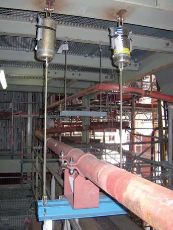
11 2 Heavy duty spring hangers Type 22 d 3 blocking device S Spring hangers type to R SW 2 H X C E B Ø d 2 SW 1 Ø A type Ø A B C Ø d 2 Ø d 3 E H R S SW 1 SW 2 X weight [kg] M56x M56x M56x M64x M64x M64x M68x M68x M68x M72x M72x M72x M80x M80x M80x Dimension E increases on loading by the corresponding spring travel (see load table on p. 2.6). Spring hanger type 22 with weldon clevis type 73 mounted Spring hanger type 22 with threaded clevis type 61 mounted Typical installation situations spring hangers type marking: set load: kn travel: mm up/down 2.8

![0 72 69 28 260 200 23 15 6.9 72 79 28 290 215 23 20 10.9 72 89 28 290 215 27 20 10.9 72 99 28 340 255 33 25 18.2 load group type Ø A B Ø d 2 Ø d 4 H X max weight [kg] 25 D2 19 90 350 M10 13 245 380 2.](/docs-images/78/76783087/images/12-2.jpg "8 25 D3 19 90 675 M10 13 470 705 4.9 25 11 18 90 200 M12 13 145 230 2.1 25 12 18 90 350 M12 13 245 380 3.1 25 13 18 90 675 M12 13 470 705 5.5 25 21 18 115 205 M12 13 150 235 3.")


12 Spring hangers Type 25 Spring hangers for seating type 25 D2 19 to Standard design, delivery from stock. Ø d 4 H B X Ø A Ø d 2 If required, the base plate type 72 can be attached to type 25. E d 6 C B type B C d 6 E [kg] 72 D load group type Ø A B Ø d 2 Ø d 4 H X max weight [kg] 25 D M D M M M M M M M M M M M M M M M M M M M M M M M M M M M M Dimensions B and X are reduced on loading by the corresponding spring travel (see load table on p. 2.5). spring hangers type marking: set load: kn travel: mm up/down For special applications, e.g. in extremely restricted spaces, spring hangers type 25 can be supplied as a trapeze unit. 2.9


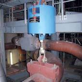
. Spring assemblies as special design for use on a power station boiler.")
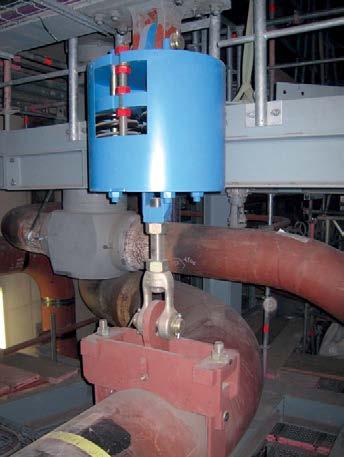
13 Heavy duty spring hangers Type 26 Ø d 4 blocking device 2 Spring hangers for seating type to SW H B X Ø d 2 Ø A type Ø A B Ø d 2 Ø d 4 H SW X max weight [kg] M56x M56x M56x M64x M64x M64x M68x M68x M68x M72x M72x M72x M80x M80x M80x Dimensions B and X are reduced on loading by the corresponding spring travel (see load table on p. 2.6). Spring assemblies as special design for use on a power station boiler. spring hangers type 26 marking: set load: kn travel: mm up/down 2.10
.")

![spring supports type 29.... marking: set load: kn travel: mm up/down typ e Ø A B C d 6 E F H Ø D S weight [kg] 29 C2 19 80 105 75 10 270 36 210 80 6 2.6 29 D1 19 90 125 95 12 195 36 145 80 8 3.](/docs-images/78/76783087/images/14-3.jpg "2 29 D2 19 90 125 95 12 305 36 245 80 8 4.3 29 D3 19 90 125 95 12 550 36 470 80 8 6.6 29 11 18 90 125 95 12 195 36 145 80 8 3.4 29 12 18 90 125 95 12 305 36 245 80 8 4.")


14 Spring supports Type 29 Ø D Spring supports type 29 C2 19 to Standard design, delivery from stock. F Ø L 1 H Ø A S E d 6 C B Load plate with integrated slide plate. When using slide plates the sliding surfaces of the counter component used should be fitted with stainless steel plating. This is indicated by the suffix SP on the type designation (e.g. clamp base type SP). type 29* with slide plate up to 180 C up to 350 C Ø L 1 29 C C D D * friction values of the sliding components, see table on p For large horizontal load displacements, beside the use of slide plates the use of clamp bases with twist-off restraints is also recommended. spring supports type marking: set load: kn travel: mm up/down typ e Ø A B C d 6 E F H Ø D S weight [kg] 29 C D D D Dimension E is independent of the load adjustment; it changes on loading by the respective spring travel (see load table on p. 2.5). Adjustment possibility + 30mm. Type 29 is supplied as standard with a galvanized load plate without a slide plate. If slide plates are used, the E dimension increases by 2.5mm. Please note table above. See also p E type E load group To bridge greater installation heights, adapted extensions can be ordered. 2.11
![Heavy duty spring supports Type 28 2 Ø D blocking device Spring support type 28 11 19 to 28 53 19 Ø L 2 Ø L 1 SW H Ø A S E B C d 6 type Ø A B C Ø D d 6 E F H S SW weight [kg] 28 11 19 510](/docs-images/78/76783087/images/15-0.jpg "530 440 420 33 405 60 330 25 46 230 28 12 19 510 530 440 420 33 535 60 450 25 46 260 28 13 19 510 530 440 420 33 835 60 730 25 46 360 28 21 19 560 580 490 420 33 450 65 370 25 46 310 28")

.")


15 Heavy duty spring supports Type 28 2 Ø D blocking device Spring support type to Ø L 2 Ø L 1 SW H Ø A S E B C d 6 type Ø A B C Ø D d 6 E F H S SW weight [kg] When slide plates are used, the sliding surfaces of the clamp base used should be fitted with stainless steel plating. This is indicated by the suffix SP in the type designation (e.g. clamp base type SP). Dimension E is independent of the load adjustment; it changes on loading by the respective spring travel (see load table p. 2.6). Adjustment possibility + 30mm. Type 28 is supplied as standard with a coated load plate without slide plate. When slide plates are used, the E dimension increases by 2mm. Please note following tables. type 28* with slide plate up to 180 C Ø L 1 Ø L type 28* with slide plate up to 350 C Ø L 1 Ø L * friction values of slide plates, see table on p Typical application spring supports type marking:... set load: kn travel: mm up/down 2.12
. Adjustment possibility + 50mm.")


16 Angulating spring supports Type 20 Angulating spring supports type 20 D2 19 to Standard design, delivery from stock. Dimension E is independent of the load adjustment and changes on loading by the respective spring travel (see load table p. 2.5). Adjustment possibility + 50mm. 6 6 S G d3 F H G R E Connection possibilities: see bolt diameter of weld-on brackets type 35 or dynamic clamps in product group 3. angulating spring support type marking: set load: kn travel: mm up/down Installation extensions for angulating spring supports type 20 D9 19 to E 37.5 A+50 L37.5 d3 Ø D min. engagement depth Installation dimensions E max with load reduction possible. Shorter L dimensions can be supplied, but then without adjustment possibility of 37.5mm. extension for angulating spring support type L dimension: mm type Ø A Ø d 3 weight E F G H R S G [kg] weld-on bracket 20 D D type for type A +50 Ø D Ø d 3 E min E max L 37.5 min L 37.5 max weight for L min [kg] pipe [kg/m] 20 D D D D Ø A 2.13


.")


17 Spring hanger trapezes Type 79 d 2 L X 2 Spring hanger trapezes (bolted version) type 79 D. 19 to Ø A nominal load [kn] Ø d 2 L max E for travel range U A B X weight [kg] L=1000mm for travel range per 100mm [kg] type 79 D M M M M M M M M M M M M M M M M Ø d 2 E L B U E 50 travel range E dim. approx see above. The 4th digit of the type designation refers to the travel range of the spring hanger 1=50mm, 2=100mm, 3=200mm. Permissible center loading of the other load cases, see table 4.4.1, p. 0.6 (nominal load 120kN, see load group 9). The E dimension increases on loading by the corresponding spring travel (see load table on p. 2.5). The L max dimensions can be lengthened by up to 2400mm on reduction of the permissible center loading by 5% per 100mm extension. When selecting the spring hanger trapeze the weight of the U profiles and the clamp base weight must be added to the operating load. When selecting the spring hanger trapeze, its total weight and the weight of the clamp bases must be added to the operating load. spring hanger trapeze type L = mm, marking:, set load: kn travel: mm up/down Spring hanger trapezes (welded version) type 79 D. 11 to B nominal load weight [kg] L=1000mm for travel range per 100mm type [kn] Ø d 2 L max B [kg] 79 D M M M M M M M M M M In restricted spaces this version can be supplied as a special design. spring hanger trapeze type L = mm, marking: set load: kn travel: mm up/down 2.14


18 Sway braces Type 27 Sway braces type 27 D2 19 to The maximum working travel including free stroke amounts to 25mm F H E d 3 load adjustment R Load adjustment is made ex works acc. to customer specifications. Ø A C37.5 The E dimension is independent of the load adjustment; adjustment possibility 37.5mm adjustment free stroke min. engagement depth SG 6 6 Connection possibilities: see bolt diameter of weld-on brackets type 35 or dynamic clamps in Product Group 3. sway brace type marking: set load: kn travel: mm up/down type nominal load [kn] set load [kn] min max spring rate Ø d 3 weld-on bracket [N/mm] Ø A C 37.5 E F H R S G type 27 D weight [kg] Extension for sway brace type 27 D9 19 to If required, sway braces can be supplied with installation extensions mounted at the factory. L37.5 d 3 min. engagement depth Ø D E 75 A 37.5 Installation dimensions Emax on load reduction possible. Shorter L dimensions can be supplied, but then without adjustment possibility of 37.5mm. extension for sway brace type L dimension: mm type A 37.5 Ø D Ø d 3 E 75 min max L 37.5 min max weight for L min [kg] pipe [kg/m] 27 D


19 Function diagram max. set load min. load strength nominal load tension travel [mm] 2 upper ball bushing joint lock nut lock nut guide pipe threaded pipe lock nut guide rod type plate with travel scale travel scale lower ball bushing joint spring plate spring compression Load and installation length are adjustable for the respective requirements (see installation and operating instructions). free stroke For LISEGA sway braces a free stroke of 0 25mm can be set. The travel is reduced in compression and tension directions in accordance with the free stroke selected. load adjustment compression force neutral position tension force Load transmission on alternating force direction 2.16
.")
 6 for design with high-temperature slide plate (up to 350 C).")

20 Telescopic spring supports Type 29 Spring supports, telescopic type 29 D1 27 to slide plate Ø D Ø L 1 As a special design of type 29 the telescopic spring supports are used for small E dimensions. s E The sliding surfaces of the clamp bases used should be fitted with stainless steel plating. This is indicated by the suffix SP in the type designation (e.g. clamp base type SP). Ø A C B d 6 The telescopic spring support is fitted as standard with a load plate with a PTFE slide plate. If required, this type can also be supplied with a high-temperature slide plate. The 6th digit of the type designation denotes the design: 7 for standard design with PTFE slide plate (up to 180 C) 6 for design with high-temperature slide plate (up to 350 C). For friction values of sliding components see table on p The E dimension depends on the load setting; it changes on loading by the respective spring travel. Adjustment possibility + 20mm. E [mm] = E on min. load [mm] adjustment load [kn] min. load [kn] x 1000 spring rate [N/mm] type Ø A B C Ø D d 6 Ø L 1 s E on min. E on max. min. load max. load spring rate load load [kn] [kn] [N/mm] weight [kg] 29 D D D spring support type marking: set load: kn travel: mm up/down 2.17
21 2 2.18


.")

 or, as with type 25/26, consists of a support")

22 Installation and operating instructions Types 21, 22, 25, 26, 29, 28, 20, 27 upper connection travel scale blocking device name plate lower connection spring plate cover plate securing strap support tube Spring hanger type 21 type 22 Spring hanger type 25 type 26 Name plate for spring hangers Transport and storage When transporting, care must be taken that connecting threads and blocking devices are not damaged. When storing in the open air the hangers must be protected from water and dirt. 2 Delivery condition If not agreed otherwise, LISEGA spring hangers are set and blocked at the desired cold position (installation condition). Special blocking devices fix the spring plates in both directions. The adjustment values can be read off the travel scale or name plate. Stamped on the name plate are: type number and if required serial number set load and spring rate operating load and travel marking and commission number inspector On the travel scale the theoretical hot position is marked with a red sticker and the theoretical cold one with a white one. In addition the position of the spring plate on the travel scale is stamped with an X. The reading is made at the lower edge of the spring plate (at the upper edge for trapezes type ). The production number is stamped on the body of the spring hanger. Depending on the connection the spring hangers are fitted at the top with an inner right-hand thread, a lug for connecting bolts or a fixed support tube. The threads are greased and sealed with plastic caps. Depending on the design, the lower connection is fitted with a right-hand thread (turnbuckle) or, as with type 25/26, consists of a support tube for the connecting rod. The spring supports types 28/29 are equipped with an adjustable support tube with a loosely seated but guided load plate. In delivery condition the support tube is screwed in and the thread greased. 3 Installation On installation, the specifications in the installation instructions for the piping systems should also be observed, especially the desired installation position of the connecting rods over the whole load chain. There are two possibilities: Spring hanger type 21 (blocked) Spring hanger type 25 (blocked) Spring hanger type 22 (blocked) Spring hanger type 26 (blocked)
 The connecting rods are to be installed at an angle to correspond to the expected horizontal")
 The connecting rods are to be installed vertically for better")


23 Spring support type 29 (blocked) Spring support type 28 (blocked) Angulating spring support type 20 (blocked) Sway brace type 27 A) The connecting rods are to be installed at an angle to correspond to the expected horizontal displacement of the pipe systems. A perpendicular position in operating condition is to be hereby expected. Cold position Rods vertical during plant operation B) The connecting rods are to be installed vertically for better controllability. A controlled angled position is thereby permitted in operating conditions. hot position Rods vertical in installation condition Hot position cold position Uniform specifications should at all events apply for the whole plant. The connecting rods and points must be connected by force-fitting. Attention must be paid to the minimum engagement depth of the threaded components. Installation of types 21, 22 The force-fit connection for type 21 is produced by screwing the connecting rods into the upper and lower connection threads. The lower connection thread is designed as a turnbuckle. Type 22 has a bolt-lug upper connection. For tightening and length regulation the turnbuckle length available in the spring hanger in each case can be used. Installation types 25, 26 Spring hangers types 25 and 26 are placed on the existing steelwork and correspondingly aligned. The position aligned is to be fixed against horizontal displacement. The force-fit connection is produced via the connecting rod, which is fed through the support tube and tightened and locked with two nuts. 2 load plate or ball bushing joint at top travel scale stop name plate base plate or ball bushing joint at bottom spring plate cover plate securing strap lock nut lock nut guide tube threaded tube lock nut guide rod Spring support type 29 Spring support type 28 Angulating spring support type 20 Sway brace type 27 angled arrangement Sway brace type 27 simple arrangement 2.20

, or several adjustable ones (type 28).")

24 minimum engagement depth minimum engagement depth Minimum engagement depth of threaded rods by example of type 21 The blocking for spring hangers and spring supports types 21, 25, 29 and 20 consist of sheet metal lamellas adjustable to any desired load position. Up to 3 blocking devices can be inserted into a spring hanger. Installation of types 28, 29 The spring supports 28 and 29, after corresponding alignment, are attached by welding or bolting the base plate to the building structure. The load distribution is applied through the load plate and an adjustable support tube (type 29), or several adjustable ones (type 28). To balance installation tolerances the support tubes may be further screwed out only to a maximum of 30mm. The instructions on p are to be followed for the correct installation of the slide plates. Installation of type 20 The angulating spring supports are fitted at the top with an adjustable ball bushing joint and at the bottom with a fixed ball bushing joint or an extension suitable for connection to a weld-on bracket type 35 or to the dynamic clamps type 36 or 37. After alignment of the angulating spring support the lower weld-on bracket is attached to the surrounding structure (see installation instructions for weld-on brackets type 35). The load distribution is applied through the upper bolt connection (weldon bracket or dynamic clamp) to the height-adjustable support tube. To balance installation length tolerances the support tube may be further screwed out only by a maximum of 50mm. Installation of type 27 The sway braces are fitted at the top with an adjustable ball bushing joint and at the bottom with a fixed ball bushing joint or an extension suitable for connection to a weld-on bracket type 35 or to the dynamic clamp type 36 or 37. The load presetting, and if necessary the free stroke, are adjusted at works according to customer specifications. After alignment of the connection points the welding of the weld-on brackets and the connection of the connection bolts of the brackets or dynamic clamps types 36/37 are carried out. The adjustable ball bushing joints permit regulation of the installation height by 37.5mm. 4 Deblocking The spring hangers/supports may only be deblocked when the set load is fully applied on all the supports making up a support system. If this is the case the blocking devices can be easily removed. If the devices are jammed, the load actually applied does not agree with the theoretical setting (see point 5, load correction). Procedures for types 21, 25, 29, 20 Removal of the securing strap: The securing strap is removed with an appropriate tool. Great care must be taken that the free ends of the metal strap do not snap upwards in an uncontrolled way. Removal of the blocking devices: The device is removed from the casing. When removing the blocking devices, proceed as a matter of principle in a systematic way, step by step, beginning with a fixed point or connection point. Never remove the devices by force! Storage of blocking devices: Type 29 with blocking devices attached 2.21


. For this, loosen the large lock nut (B).")

).")


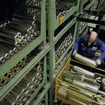
25 2 Removed blocking devices must either be stored separately or, for really safe keeping, placed in the optional LISEGA storage racks on the hanger. Type 21, 22 Load adjustment can be carried out by loosening or tightening the turnbuckle. securing clamp fixing screw Type 25, 26 Load adjustment can be made by loosening or tightening the load nut. If the blocking devices are found to be missing, e.g. at revisions, they can be supplied by LISEGA at short notice. Procedure for types 22, 26, 28 Removal of blocking devices: The blocking devices are removed from the casing. Storage of blocking devices: Removed blocking devices must either be stored separately or, insofar as sufficient space is available and freedom of movement for the spring plate is allowed, screwed to the cover plate. 5 Load correction Before every load adjustment, under all circumstances the technical department responsible must be consulted. Type 20, 28, 29 Load adjustment can be made by adjusting the support tube of the spring supports. Load correction and adjustment of the free stroke, type 27 Load adjustment is made by rotating the outer threaded tube (A). For this, loosen the large lock nut (B). To maintain the E dimension the play thereby created must be balanced by readjusting the guide tube (C). A free stroke can be set for the LISEGA sway braces. For this, the guide tube (C) opposite the inner guide rod (D) must be correspondingly screwed out (loosen middle lock nut (E)). The working travel is reduced in the direction of compression according to the free stroke selected. D C B 6 Auxiliary devices To facilitate load adjustment or deblocking, an auxiliary installation device can be supplied for the higher load groups. The load transfer is then taken up by means of a hydraulic pump. This is operated by LISEGA technicians. 7 Inspection and maintenance The flawless functioning of the spring hangers can be checked in every operating situation by noting the position of the spring plate. Under normal operating conditions no maintenance is required. A E The blocking devices of types 22, 26 and 28 consist of threaded studs and nuts by means of which any load setting desired can be carried out. hydraulic cylinder hydraulic cylinder hydraulic cylinder (2 units) 2.22
SPRING HANGERS, SPRING SUPPORTS PRODUCT GROUP
 SPRING HANGERS, SPRING SUPPORTS PRODUCT GROUP VARIABLE SPRING ELEMENTS CONTENTS PAGE 0 Spring hangers, spring supports, sway braces.1 Load table for spring hangers, spring supports and other spring elements.3
Pipe clamps, clamp bases, connecting parts
 Pipe clamps, clamp bases, pipe connecting parts 4 pipe Pipe clamps, clamp bases, connecting parts PRODUT 4 GROUP Pipe clamps, clamp bases, pipe connections ontents Page Field of application... 4.1 Product
1 Variable spring supports Design Instructions
 Design Instructions 1.1 Application Rigid supporting structures are not capable to accommodate vertical displacement or large horizontal forced travels of piping. This nodes should be supported by spring
STRUCTURAL ATTACHMENT ELEMENTS
 STRUCTURAL ATTACHMENT ELEMENTS 7 PRODUCT GROUP 7 STRUCTURAL ATTACHMENTS, TRAPEZES CONTENTS PAGE 0 Structural attachments, trapezes 7.1 Weld-on clevis type 73 7.2 Weld-on eye plate type 75 7.2 Weld-on
Constant hangers, constant supports
 Constant hangers, constant supports 1 Constant hangers, constant supports PRODUCT 1 GROUP Constant hangers, constant supports Contents Page Field of application...1.1 Advantages and design overview...1.3
Hydraulic Valves. Experience plus ideas
 Hydraulic Valves Experience plus ideas Contents Type/Page Product information Hydraulic valves Function description Non-return valves Pg. 271 Non-return valves Pg. 272-273 RHD RHDI RHV RHZ Function description
01 09 Installation guidelines Air suspension units GL70 GL70HD GL70L GN Air suspension units GL70 GL70HD GL70L
 01 09 Installation guidelines Air suspension units GL70 GL70HD GL70L GN0031-1 Air suspension units GL70 GL70HD GL70L can be identified by the hanger brackets with a welded-on support for the eccentric
Ball Rail Systems RE / The Drive & Control Company
 Ball Rail Systems RE 82 202/2002-12 The Drive & Control Company Rexroth Linear Motion Technology Ball Rail Systems Roller Rail Systems Standard Ball Rail Systems Super Ball Rail Systems Ball Rail Systems
Kaydon white paper. The importance of properly mounting thin section bearings. an SKF Group brand. by Rob Roos, Senior Product Engineer
 The importance of properly mounting thin section by Rob Roos, Senior Product Engineer an SKF Group brand Figure 1 Radial Load Reversing Thrust Overturning Moment Thin section ball have a much thinner cross-section
Technical specifications
 Technical specifications 0 Technical specifications Product 0 group Technical specifications Contents Page 1. Standard Supports, requirements and definition...0.1 2. LISEGA Standard Supports...0.1 3.
Elastomeric Bearings & Industrial Products. Elastomeric Bearings & Industrial Products. EA Bearings. EA Bearings. EA Series Standard Bearings
 EA Bearings EA Bearings EA Series Standard Bearings Support and Installation Part Number These bearings are designed to support a vertical load up to 2000kN with the constant bearing temperature not exceeding
Precision Modules PSK
 Precision Modules PSK 2 Bosch Rexroth AG Precision Modules PSK R999000500 (2015-12) Identification system for short product names Short product name Example:: P S K - 050 - N N - 1 System = Precision Module
SECTION 11 INTERMODAL EQUIPMENT
 SECTION 11 INTERMODAL EQUIPMENT ROA MANUAL SCHEDULE OF AMENDMENTS SECTION 11 AMENDMENT NUMBER PAGES AMENDED AMENDMENT SUMMARY DATE ISSUED TABLE OF CONTENTS Section Description Page No. 11.1 SCOPE... 11-1
The GK units differ from the LK units in that the springs of the GK units have a spring eye at the front.
 01 09 Installation guidelines Mechanical suspension units GK LK GN0032-0 Mechanical suspension units GK LK The GK units differ from the LK units in that the springs of the GK units have a spring eye at
Linear Shaft Motors in Parallel Applications
 Linear Shaft Motors in Parallel Applications Nippon Pulse s Linear Shaft Motor (LSM) has been successfully used in parallel motor applications. Parallel applications are ones in which there are two or
Round Fine Centering for the mold construction. The development. Advantages
 Round Fine Centering for the mold construction The development Advantages Durability: for mass production Backlash-free for very precise mold alignment Shorter cycle times High initial load capacity at
Shaft-Hub-Connections
 Stand: 14.01.2010 Shaft-Hub-Connections Shrink Discs Cone Clamping Elements Star Discs 36 Edition 2012/2013 RINGSPANN Eingetragenes Warenzeichen der RINGSPANN GmbH, Bad Homburg Table of Contents Introduction
eline Ball Screw Assemblies
 eline Ball Screw Assemblies R310EN 3314 (2005.06) The Drive & Control Company R310EN 3314 (2005.06) Bosch Rexroth AG 3 Product Overview 4 Technical Data 6 with Screw-in Single Nut ZEV-E-S Single fixed
Profi le rail guides LLR
 Profi le rail guides LLR Content The SKF brand now stands for more than ever before, and means more to you as a valued customer. While SKF maintains its leadership as the hallmark of quality bearings throughout
ORIGA Pneumatic Linear Drives OSP-L
 ORIGA Pneumatic Linear Drives OSP-L Very long lifetime and lowest leakage A NEW Modular Linear Drive System With this second generation linear drive Parker Origa offers design engineers complete flexibility.
Chrysler A-Body Tubular A-Arms Installation Instructions A-ARM INSTALLATION
 1967-1976 Dodge Demon 1112 67-72 Chrysler A-Body Tubular A-Arms Installation Instructions Thank you for your purchase of this Hotchkis Performance product. Your A-Arm set was designed with the performance
For advanced drive technology CLAMPEX. Shaft-Hub-Connection. KTR Precision Joints CLAMPEX
 technology CLAMPEX Shaft-Hub-Connection CLAMPEX KTR Precision Joints 07 technology Table of contents Page Brief information 09 Selection and calculation -5 CLAMPEX -Selection Shaft diameter = d 0 10 0
Product overview. Joints. Circlips for ball seats DIN K0714. Quick plug couplings with radial offset compensation K0709. Page 837.
 Joints 825 Product overview Joints Quick plug couplings with radial offset compensation K0709 Quick plug couplings with radial offset compensation and screw-on flange K0710 Quick plug couplings with angular
...our linkages, your solution. Rod Ends
 ...our linkages, your solution Technical Information Introduction All of our rod ends incorporate either a plain spherical bearing, ball bearing, or roller bearing. Below is an overview of each type. Plain
For advanced drive technology CLAMPEX. Shaft-hub-connection. KTR Precision joints CLAMPEX
 technology CLAMPEX Shaft-hub-connection CLAMPEX KTR Precision joints 227 technology Table of contents Page Brief information 228 Selection and calculation 25-255 CLAMPEX -Selection Shaft diameter = d 0
V SWISS MADE LINEAR TECHNOLOGY
 Compact units Excerpt from main catalogue SWISS MADE LINEAR TECHNOLOGY V 11-15 Line Tech compact units Table of contents Product overview 106 107 Design fundamentals / Lubrication / Maintenance 108 Profile
Mounting Overlap Shield. Face Clamps. Gap. Seat Depth. Lead In Chamfer. Loose Fit.
 Mounting Introduction: Reali-Slim thin section ball bearings have a crosssection thickness that is much thinner than standard bearings of the same diameter, and are therefore more sensitive to shaft and
PIPINGSOLUTIONS, INC.
 Piping Stress Analysis Where do I start? The following information will take you step-by-step through the logic of the data collection effort that should occur prior to beginning to model a piping system
Compact Modules. with ball screw drive and toothed belt drive R310EN 2602 ( ) The Drive & Control Company
 The Drive & Control Company") with ball screw drive and toothed belt drive R310EN 2602 (2007.02) The Drive & Control Company Bosch Rexroth AG Linear Motion and Assembly Technologies Ball Rail Systems Roller Rail Systems Linear Bushings
with ball screw drive and toothed belt drive R310EN 2602 (2007.02) The Drive & Control Company Bosch Rexroth AG Linear Motion and Assembly Technologies Ball Rail Systems Roller Rail Systems Linear Bushings
Contents. Page. 1. Product description. 2. The AXC line of linear axes. 3. AXLT line of linear tables. AXC and AXS product overview...
 SNR Industry Contents Page 3 1. Product description AXC and AXS product overview... 6-8 Dynamic load ratings of the linear motion systems... 9 Compact modules... 10-11 Linear tables... 12 Telescopic axes...
Wixroyd Universal Joints SIMPLE UNIVERSAL JOINTS DOUBLE UNIVERSAL JOINTS QUICK COUPLING UNIVERSAL JOINTS
 Wix_set_4.qxp 11/10/2006 18:33 Page 1 Wixroyd are used in a wide variety of applications. 6514/28 There are a variety of universal joints available. SIMPLE UNIVERSAL JOINTS 1) - find their field of application
ORDERING: Specify size, figure number, description, nominal pipe size or special O.D. and C-to-C dimension. C - C LOAD lb.
 Fig. 2110 www.pipingtech.com/fig2110 Sway Strut with 4 of Adjustment Engineered spring supports option 1 option 2 ORDERING: Specify size, figure number, description, nominal pipe size or special O.D. and
Load Cell for Manually Operated Presses Model 8451
 w Technical Product Information Load Cell for Manually Operated Presses 1. Introduction... 2 2. Preparing for use... 2 2.1 Unpacking... 2 2.2 Using the instrument for the first time... 2 2.3 Grounding
Ball Screw Assemblies eline. The Drive & Control Company
 Ball Screw Assemblies eline The Drive & Control Company 2 Bosch Rexroth Corp. Linear Motion and Assembly Technologies eline BSA R310A 3314 (2005.04) Linear Motion Technology Ball Rail Systems Standard
3. BEARING ARRANGEMENT DESIGN
 3. BEARING ARRANGEMENT DESIGN 3.1 GENERAL PRINCIPLES OF ROLLING BEARING ARRANGEMENT DESIGN Rotating shaft or another component arranged in rolling bearings is guided by them in radial as well as in axial
R310EN 2211 ( ) The Drive & Control Company
 The Drive & Control Company") eline Ball Rail Systems R310EN 2211 (2006.04) The Drive & Control Company Bosch Rexroth AG Linear Motion and Assembly Technologies Ball Rail Systems Roller Rail Systems Linear Bushings and Shafts Ball
eline Ball Rail Systems R310EN 2211 (2006.04) The Drive & Control Company Bosch Rexroth AG Linear Motion and Assembly Technologies Ball Rail Systems Roller Rail Systems Linear Bushings and Shafts Ball
Precision Modules PSK
 Precision Modules PSK The Drive & Control Company Rexroth Linear Motion Technology Ball Rail Systems Roller Rail Systems Standard Ball Rail Systems Super Ball Rail Systems Ball Rail Systems with Aluminum
CLASSIFICATION OF ROLLING-ELEMENT BEARINGS
 CLASSIFICATION OF ROLLING-ELEMENT BEARINGS Ball bearings can operate at higher speed in comparison to roller bearings because they have lower friction. In particular, the balls have less viscous resistance
> piston force up to 20,1 kn. > operating pressure 250/350 bar. > chemically nitrided body. > piston force up to 44,0 kn. > operating pressure 350 bar
 Vertical and link CLAMPS for DEMANDING TASKS vertical CLAMP > piston force up to 20,1 kn > operating pressure 250/350 bar > chemically nitrided body link CLAMP > piston force up to 44,0 kn > operating
MECHANICS. Aluminium profiles Linear guides Drive elements Linear units Rotational units
 Aluminium profiles...2-2 Linear guides...2-18 Drive elements...2-44 Linear units...2-52 Rotational units...2-94 Aluminium profiles Aluminium profiles PP profiles Panel profiles PP PP 100 PP 1 PP 200 Overview
Selection Tool. on the Internet at in the section MÄDLER -Tools. Other sizes and designs on request. Connecting Shafts Page 766
 Couplings Overview Friction Clutches Friction Clutches Type B Axial Arrangement Friction Clutches Type C Transversal Flexibility Sliding Hubs with Torsionally-Flexible Coupling Multi-Disk Friction Clutches
Precision Modules PSK. The Drive & Control Company
 Precision Modules PSK The Drive & Control Company 2 Bosch Rexroth Coporation Precision Modules PSK R310A 2414 (2008.07) Linear Motion and Assembly Technologies Ball Rail Systems Roller Rail Systems Linear
DESIGN OF MACHINE MEMBERS - I
 R10 Set No: 1 III B.Tech. I Semester Regular and Supplementary Examinations, December - 2013 DESIGN OF MACHINE MEMBERS - I (Mechanical Engineering) Time: 3 Hours Max Marks: 75 Answer any FIVE Questions
Roller chain idler sprocket units Idler pulley units
 Roller chain idler sprocket units Idler pulley units Roller chain idler sprocket units, idler pulley units Page Product overview Roller chain idler sprocket units, idler pulley units... 334 Design and
BEARINGS The lower bearing assemble is constructed to allow continuous operation when fully submerged in wastewater.
 GENERAL SPECIFICATION INTENT The equipment to be supplied by manufacturer includes the screw pumps, support for the drive unit, profile plates, motors, gearboxes, couplings, guards, upper and lower bearing
STRAIGHT CONVEYOR UNITS AND RIGHT-ANGLE TRANSFER
 FICHE TECHNIQUE AIRPORT \ In general, conveyor units injecting luggage on downstream conveyor units, positioned at 90, operate in two ways: Automatic direction Two directions, for flow separation and maintenance
Globe Valve Type Fig. 1 Type 3241 Globe Valve. Mounting and Operating Instructions EB EN
 Globe Valve Type 3241 Fig. 1 Type 3241 Globe Valve Mounting and Operating Instructions EB 8015-1 EN Edition July 2012 Contents Contents Page 1 Design and principle of operation.................... 4 2
V SWISS MADE LINEAR TECHNOLOGY
 Excerpt from main catalogue inear modules V 11-15 SWISS MDE INER TECHNOOGY ine Tech inear modules Table of contents Product overview 6 7 Design fundamentals / ubrication / Maintenance 8 Profile cross-sections
PLE PLE CHARACTERISTICS. Travel. Travel speed. Acceleration. Temperature. Special versions APPLICATION AREAS. PLE max.
 PLE PLE PLE applications 67 PLE dimensions 68 PLE types 69 PLE sizes 71 PLE parts 72 PLE assembly 73 PLE part numbers 76 PLE CHARACTERISTICS The PLE with aluminum stays is available as PLE with plastic
Edition 1 August Overhead Rail System. Models ZRAT, ZRA1, ZRA2 & ZRS2/3
 65985 Edition August 007 Overhead Rail System Models ZRAT, ZRA, ZRA & ZRS/ Table of Contents ZRAT Aluminum Rail & Components... Engineering Data for ZRAT Aluminum Rail... How to Order ZRAT Aluminum Runway
Rodless Pneumatic Cylinders Series OSP-P
 Rodless Pneumatic Cylinders Series OSP-P System Concepts & Components... 2-5 Technical Data... 7-9 Dimensions... 10-15 Active rakes... 16-19 Accessories (Mounts & Supports)... 20-29 Ordering Information...30
Is Low Friction Efficient?
 Is Low Friction Efficient? Assessment of Bearing Concepts During the Design Phase Dipl.-Wirtsch.-Ing. Mark Dudziak; Schaeffler Trading (Shanghai) Co. Ltd., Shanghai, China Dipl.-Ing. (TH) Andreas Krome,
PLE PLE CHARACTERISTICS. Travel. Travel speed. Acceleration. Temperature. Special versions APPLICATION AREAS. PLE max.
 PLE load / (kg/m) inner height / (mm) 66 24 20 16 12 8 4 118 115 80 50 30 16 7 0 0 7 PL E 220 PL E 3 2 0 PLE 520 closed + open PL E 620 2 4 6 8 free carrying length Lf / (m) PLE max. 6 m free carrying
LOCKED SERIES. Machine Failures. General Information. set up. maintenance. reconditioning. repair 30.4%
 General Information LOCKED SERIES 2 Lowering machinery process costs is key in today s world. According to a recent study approximately a third of all machine stoppages result in unexpected damage and
Vibration damping precision couplings
 Vibration damping precision couplings In light of the advantages of elasticity, strength, resilience, and damping effects, elastomer materials are now being used in most areas of mechanical engineering.
T95 Load Cell Assembly for Silo, Tank & Vessel Weighing and Axle Weighing
 T95 Load Cell Assembly for Silo, Tank & Vessel Weighing and Axle Weighing Capacities 2t to 20t Stainless Steel Load Sensor OIML C3 approved Integrated Lift Off Prevention Load cell is always in Tension
Heavy-Duty Rod Ends - Male with integral spherical plain bearing
 Heavy-Duty Rod Ends - Male with integral spherical plain bearing 65700 Order No. Thread (hand) d 1 l 1 d 2 d 3 d 4 l 2 l 3 X g H7 65700.W0005 Right 5 33 M 5 11,11 18 20 9 14 65700.W0006 Right 6 36 M 6
NEEDLE ROLLERS. Polígono Indutrial O Rebullón s/n Mos - España -
 NEEDLE ROLLERS Needle rollers In certain applications, the limited amount of space available for bearings and the loads to be supported require the use of a full complement of needles independent of any
Axial-radial cylindrical roller bearings
 Axial-radial cylindrical roller bearings Designs and variants.............. 320 Bearing data..................... 321 (Boundary dimensions, tolerances) Product table 5.1 Axial-radial cylindrical roller
Eurocode Compliant. supplement. groundworks technical reference section 4: double acting hydraulic braces. supershaft plus technical details
 groundworks technical reference section 4 : double acting hydraulic braces supplement supershaft plus technical details Page 1 Eurocode Compliant Issue 1 supershaft plus (SSP) 1. Introduction Supershaft
MULTI CROSS RILLO. Highly flexible tyre coupling with taper bushings
 MULTI CROSS RILLO Highly flexible tyre coupling with taper bushings Maschinenfabrik Dipl.-Ing. Herwarth Reich GmbH Vierhausstr. 53 D-44807 Bochum P.O. Box 10 20 66 D-44720 Bochum Tel.: +49 / (0)234 / 959
VARIABLE SPRING SUPPORTS BV35, BV70, BV140, BV210
 SUPPORTS 35, 70, 140, 210 GENERAL Variable spring supports are used for supporting pipework, vessels, columns and pipe connections to large tanks, that are subject to thermal movement and/or subsidence.
Standard Supports 2020
 Standard Supports 2020 Standard Supports 2020 dition: September 2016 The LISG product program covers all components required for the implementation of modern concepts in the support of pipe systems. These
PRECISION BELLOWS COUPLINGS
 PRECISION BELLOWS COUPLINGS Bellows couplings are used where precise rotation, high speeds, and dynamic motion must be transmitted. They exhibit zero backlash and a high level of torsional stiffness, offering
SFI SPECIFICATION 35.2 EFFECTIVE: DECEMBER 29, 2014 *
 SFI SPECIFICATION 35.2 EFFECTIVE: DECEMBER 29, 2014 * PRODUCT: Heavy Duty Stock Car Steel Wheels 1.0 GENERAL INFORMATION 1.1 This SFI Specification establishes uniform test procedures and minimum standards
RACK JACK. Synchronous Lifting Systems
 RACK JACK Synchronous Lifting Systems RACK JACK (ROUND RACK TYPE) Operation The Rack Jack from WMH Herion provides simple synchronous lifting motion. The system of rack and pinion transforms linear motion
O SL. BPW Original spare parts Air suspensions series O / SL / AL BPW BERGISCHE ACHSEN BPW ORIGINAL SPARE PARTS. BPW Original spare parts
 BPW riginal spare parts Air suspensions // BPW BERGISCHE ACHSEN BPW riginal spare parts Air suspensions series / / BPW RIGIN SPARE PARTS BPW riginal spare parts Air suspensions Contents Page Air suspension
Inner block. Grease nipple. Fig.1 Structure of LM Guide Actuator Model KR
 LM Guide ctuator Model LM Guide + all Screw = Integral-structure ctuator Stopper Housing all screw Inner block Grease nipple Outer rail earing (supported side) Housing Stopper Double-row ball circuit earing
R310EN 2302 ( ) The Drive & Control Company
 The Drive & Control Company") R31EN 232 (26.4) The Drive & Control Company Bosch Rexroth AG Linear Motion and Assembly Technologies Ball Rail Systems Linear Bushings and Shafts Ball Screw Drives Linear Motion Systems Basic Mechanical
R31EN 232 (26.4) The Drive & Control Company Bosch Rexroth AG Linear Motion and Assembly Technologies Ball Rail Systems Linear Bushings and Shafts Ball Screw Drives Linear Motion Systems Basic Mechanical
MAURER Pot Bearings. Technical information, dimensions and weights
 MAURER Pot Bearings Technical information, dimensions and weights Design Function assembly rubber pad scale and pointer cover Fixed pot bearing TF Generally mobile pot bearing TGa Generally mobile pot
Installation instructions
 Service Installation instructions Audi A3 (8V3) 2012 Roof bars 8V3.071.126 for vehicles with bright moulding package (PR no. 4ZB) and roof bars 8V3.071.126.L for vehicles with black moulding package (PR
SUSPENSION 04 CLAMPS
 SUSPENSION CLAMPS 04 4 SUSPENSION CLAMPS 57 Contents General... 58 Suspension clamp trunnion type, forged,... 63 Suspension clamp trunnion type, forged, with bigger angle of deflection, for aluminium based
Tension and Compression Load Cell Model 8435
 Technical Product Information w Tension and Compression Load Cell 1. Introduction... 2 2. Preparing for use... 2 2.1 Unpacking... 2 2.2 Using the instrument for the first time... 2 2.3 Grounding and potential
Suspension tracks. Suspension tracks H 38. We put things in motion
 H 38 Our manual suspension tracks are also suitable for small and medium-sized trade companies. They are particularly distinguished by: Overhead conveyor system with Müsing spider assembly. Targeted material
ROSTA RUBBER SUSPENSION UNITS. Multifunctional Modules for the Machine Industries. guiding tensioning absorbing ROSTA
 RUBBER SUSPENSION UNITS Multifunctional Modules for the Machine Industries guiding tensioning absorbing Product Range Modules Rubber Suspension Unit Type DR-S Page 19 Housing made out of steel, inner square
L Standard Parts for Mould Making
 A Die Sets B Precision Ground Plates and Flat Bars C Lifting and Clamping Devices Shanks, Lifter Studs and Lifting Hooks, Eyebolts Clamping Claws, Screws and Bolts D Guide Elements E Ground Precision Components
INSTALLATION AND OPERATION
 Industrial Type Turbine Flowmeter NT Hygienic Type Turbine Flowmeter BNO Low Flow Pelton Wheel Flowmeter NS INSTALLATION AND OPERATION Nixon Flowmeters Ltd. Leckhampton, Cheltenham, Glos UK Tel. 0044 (0)
Product overview. 10 Bosch Rexroth Corporation Compact Modules R310A 2602 ( ) Compact Modules CKK. Compact Modules with ball screw drive (CKK)
 Compact Modules CKK. Compact Modules with ball screw drive (CKK)") 10 Bosch Rexroth Corporation R310A 2602 (2008.09) CKK with ball screw drive (CKK) Product overview are precision, ready-to-install linear motion systems characterized by their high performance and compact
10 Bosch Rexroth Corporation R310A 2602 (2008.09) CKK with ball screw drive (CKK) Product overview are precision, ready-to-install linear motion systems characterized by their high performance and compact
Ball. Ball cage. Fig.1 Structure of Caged Ball LM Guide Actuator Model SKR
 Caged all LM Guide Actuator Model Inner block all screw shaft Grease nipple Outer rail all cage all Structure and Features Fig.1 Structure of Caged all LM Guide Actuator Model Caged all LM Guide Actuator
Miniature Ball Rail Systems
 R310EN 2210 (2004.06) The Drive & Control Company 2 Bosch Rexroth AG Linear Motion and Assembly Technologies Miniature-BRS R310EN 2210 (2004.06) Linear Motion Systems Ball Rail System Standard Ball Rail
3.2 lean SL 5 Technical data & dimension sheets lean SL series Technical data
 3.2.1 lean SL series Technical data 3.2 lean SL 5 Technical data & dimension sheets 3.2.1 lean SL series Technical data lean SL lean SL double! Make sure that the article number refers to the correct pinion
Dynamic Elements Linear Slides Mechanical Drive Elements Accessories for Mechanical Drive Elements
 8 Dynamic Elements Mechanical Drive Elements Accessories for Mechanical Drive Elements The Dynamic Elements product group of the MB Building Kit System contains components which enable precise linear movement.
Townsend Bearings. Rosta Tensioner Devices. Revision 1
 Townsend Bearings Rosta Revision 1 Tensioning Technology Chain Tensioning Roller chains are power transmission components with positive transmission which, by virtue of their design are subject, depending
928 Specialists Rear Sway Bar Installation
 928 Specialists Rear Sway Bar Installation This document is also available for download on our website (www.928gt.com/rearswaybarinstall.htm). Any new revisions to these original instructions can be found
Scion Tc Rear Endlink Installation Instructions
 Scion Tc Rear Endlink Installation Instructions Tools needed: 14mm sized box wrench 15mm sized box wrench Ramps Creeper Rag 14mm Socket Set Ruler Step 1: Back your tc onto the ramps. Note- It is imperative
Features of the LM Guide
 Features of the Functions Required for Linear Guide Surface Large permissible load Highly rigid in all directions High positioning repeatability Running accuracy can be obtained easily High accuracy can
Features of the LM Guide
 Features of the Functions Required for Linear Guide Surface Large permissible load Highly rigid in all directions High positioning repeatability Running accuracy can be obtained easily High accuracy can
Technical Description Edition 2007 Mounting, maintenance and repair of propshafts with flanged universal joints
 Technical Description Edition 2007 Mounting, maintenance and repair of propshafts with flanged universal joints 1. Recommendations Assembly, disassembly, maintenance and repair of propshafts should be
External Gear Pumps Series F
 External Gear Pumps Series F RA 10089/08.11 Replaces: RA 10097 1/60 AZPF-... Fixed pumps Size 4.0...28 cm 3 /rev (.25-1.71 in 3 /rev) Overview of contents Contents Page General 2 Product overview 3 single
Installation and Operational Instructions for EAS - HTL housed overload clutch Sizes 01 3 Type 490._24.0
 Please read these Operational Instructions carefully and follow them accordingly! Ignoring these Instructions may lead to malfunctions or to clutch failure, resulting in damage to other parts. Contents:
Crossed Roller Ways. Description of each series and Table of dimensions. Anti-Creep Cage Crossed Roller Way
 Crossed Roller Ways Description of each series and Table of dimensions Crossed Roller Way Page - to -7 Anti-Creep Cage Crossed Roller Way Page - to - Crossed Roller Way Unit Page - to - In the table of
FUNCTION OF A BEARING
 Bearing FUNCTION OF A BEARING The main function of a rotating shaft is to transmit power from one end of the line to the other. It needs a good support to ensure stability and frictionless rotation. The
RE / STAR Tolerance Rings STAR Ball Knobs, Knob and Lever Type Handles
 RE 2 970/.99 STAR Tolerance Rings STAR Ball Knobs, Knob and Lever Type Handles STAR Tolerance Rings Product Overview Tolerance rings are made of hard, embossed spring steel strip and belong to the class
RIGIFLEX -N RADEX -N. Steel laminae coupling. Steel laminae coupling. You will find continuously updated data in our online catalogue at
 117 Table of contents 117 Coupling selection steel laminae coupling 119 Description of coupling 121 General information 122 Types and applications 123 Technical data 124 Standard types 126 Special types
FRONT SUSPENSION GROUP 2 FRONT SUSPENSION 2-1 CONTENTS SPECIFICATIONS VC-1, VC-2, VC-3 VY-1 TOOL LIST. Page
 GROUP 2 FRONT SUSPENSION CONTENTS Page Specifications 1 Tool List.... 1 Torque Reference 2 Preparation for Measuring Front End Alignment... 2 Front Suspension Height Adjustment 3 Front Suspension Alignment
Profile rail guides LLT
 Profile rail guides LLT Contents The SKF brand now stands for more than ever before, and means more to you as a valued customer. While SKF maintains its leadership as the hallmark of quality bearings throughout
2. Remove front wheels.
 1 PARTS DIAGRAM 2 Installation Instructions: (PASSENGER SIDE) 1. Place jack under center of RUV front end and lift until front wheels clear the ground. Be careful to support the RUV properly so that it
3A TECHNOLOGIES 262, POR RAMANGAMDI GIDC ESTATE, VADODARA, GUJARAT, INDIA 3A TECHNOLOGIES. Works: REGISTERED OFFICE
 REGISTERED OFFICE 3A TECHNOLOGIES 310, PUJER COMPLEX, SUBHANPURA, VADODARA 390 023 GUJARAT, INDIA PH: +91-265-3088 691, FAX:+91-265 2292 165 E-Mail: sales@3atech.net Web: Works: 3A TECHNOLOGIES 262, POR
SERIES BMA, SUBMINIATURE BLIND MATE CONNECTORS
 SERIES, SUBMINIATURE BLIND MATE CONNECTORS DESCRIPTION CONTENTS PAGE HUBER+SUHNER blind mate connectors open up special dimensions in microwave applications up to 18 GHz. HUBER+SUHNER offers a range of
ND DYNAMOC .STATIC STR INTS BERGEN-PATERSON PIPESUPPORT CORPORATION DESIGN INFORMATION WOBURN, MASSACHUSETTS 01888
 CATALOG 82 ENGINEERING SUPPLEMENT NO.3.STATIC ND DYNAMOC STR INTS DESIGN INFORMATION BERGEN-PATERSON PIPESUPPORT CORPORATION WOBURN, MASSACHUSETTS 01888 Bergen-Paterson markets the widest selection of