INSTALLATION AND MAINTENANCE OF TOP LOADING ARM
|
|
|
- Theresa Boone
- 6 years ago
- Views:
Transcription

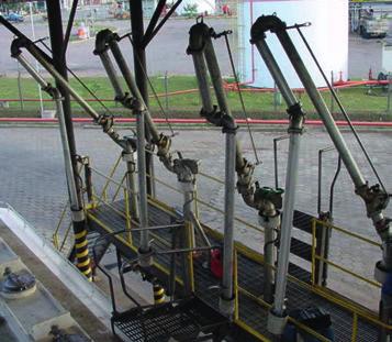

1 INSTALLATION AND MAINTENANCE OF TOP LOADING ARM D

2
3 TABLE OF CONTENTS 1. INTRODUCTION SPECIFICATION OF THE REDLANDS LOADING ARM INSTALLING THE LOADING ARM 3.1. Installation Procedures MAINTENANCE SWIVEL JOINT MAINTENANCE Tools required Disassembling the Swivel joint Assembly and maintenance of the Swivel Joint SPARE PARTS FLOW SHUT-OFF 417 DEAD MAN VALVE Introduction INSTALLING THE 417 FLOW SHUT-OFF VALVE VALVE MAINTENANCE Tools required Valve maintenance INSTALLING THE 417 FLOW SHUT-OFF VALVE inch 417 Valve Model inch 417 Valve Model INSTRUCTIONS FOR ASSEMBLING REMOTE CONTROL (1000-R-3 & 4) VACUUM BREAKER VALVE 476 SA COMPONENTS OF THE 417 FLOW SHUT-OFF VALVE inch 417 Valve inch 417 Valve TORSION SPRING 788 & Tools required for torsion spring How to adjust torque DRAWING OF 788 SPRING Components of torsion spring 788 assembly DRAWING OF 789 SPRING Components of torsion spring 789 assembly COMPRESSION SPRING How to adjust torque COMPRESSION SPRING Components of the compression spring assembly CONCLUSION 31 D
4 1. INTRODUCTION Redlands loading arms are versatile arms commonly used at facilities where vehicles are loaded from above. Composed of swivel joints (360 rotation) to provide better mobility and designed to cover a larger sweeping range of compartments, being an excellent choice for loading rail cars and/or tank trucks with several compartments. 2. SPECIFICATION OF REDLANDS LOADING ARMS There are three (3) standard top loading arm designs supplied by REDLANDS: the B- series, C-series and E-series. Each model type can be specified with a compression spring or a torsion spring, and can be supplied in various diameters, depending on the desired flow rate. B-Series. Consists of: Torsion/compression spring set, extension arm (boom), main pipe and drop tube. C-Series. Consists of: Torsion/compression spring set, main pipe, intermediate pipe and drop tube. E-Series. Consists of: Torsion/compression spring set, main pipe and drop tube. 4
5 3. INSTALLING THE LOADING ARM This manual encompasses the general instructions for installation and maintenance of REDLANDS loading arms and respective components. Prior to installing the REDLANDS loading arm, make sure the pipes are clean and free of any fouling, in order to assure smooth operation and long life of the sealing seals and seats, as any debris or dirt can damage them permanently. Because the arm will always work full up to the flow shut-off valve, it s vitally important to install a pressure relief system, due to possible thermal expansion of the product Installation procedures 1. Remove the loading arm from the protective wood packaging with the aid of a hoist, forklift, or similar equipment. 2. Connect the ANSI flange of the swivel joint at the base to the corresponding waiting flange of the supply line with its respective sealing gasket, and secure them using cap screws, nuts and washers. 3. Move the arm, checking for balance of the assembly with the torsion spring or compression spring. NOTE: The spring set is shipped from our factory already preset. If necessary, carry out the adjustment procedure described in items 14 and MAINTENANCE CAUTION: Before carrying out any maintenance on the arm, make sure it is not pressurized and has no product within it. 5
6 5. SWIVEL JOINT MAINTENANCE 5.1. Tools required One ¼ Allen wrench. One ¾ open-end or box-end wrench. One 5/16 open-end or box-end wrench. Grease and brush. One Vise (if available at the site). Image 1. Tools for assembly and maintenance Disassembly of the Swivel Joint 1. Attach the swivel joint female body to a bench vise with the nuts of the ball channels facing downward. If a vise is not available, hold it firmly so that it does not move. 2. With a ¾ open-end or box-end wrench, unscrew the top nut with light pressure only enough to loosen the assembly. Unscrew the retaining screws of the ball bearings with a ¼ Allen wrench until the screw and nut come loose from the female body. 3. Slowly rotate the male insert to the left and right, as the ball bearings come out of the set through the hole to empty each raceway. Attention: remove all of the ball bearings carefully. To avoid the risk of losing them, place them in a separate container for easy location when it s time for re-assembly. 6


7 4. Remove the male insert from inside the female body and keep the dust guard attached to the channel, so that it is completely removed from within the chamber. 5. Remove the o-ring located on the inner housing of the female body. Separate all the components necessary for re-assembly of the swivel joint Assembly and maintenance of the Swivel Joint 1. Clean the male insert and all the inner housing of the female body, removing the used grease. Flip the female body over with the ball bearing holes facing upward and re-secure it to a vise or tightly hold the swivel joint so it does not move. Image 1. Clean the inside of the female body housing. Image 2. Secure the female body to a vise. 2. With a brush, apply new grease around the inner housing of the female body. Image 3. Apply the grease with a brush. Image 4. Line the entire housing with grease. 7


8 3. Before inserting the o-ring into the female body, stretch it so that fits perfectly onto its seat. The O-ring is very important to seal the swivel joint, because if there are any gaps or it is not seated properly, there may be a risk of leakage. Image 5. Place the ring into the female body. Image 6. The o-ring should be adjusted in the female body. 4. If the same ball bearings must be re-used, clean them carefully. We suggest replacing them with new ones. Clean the dust guard, and place it around the appropriate channel of the male insert. See photo below. Image 7. Clean the dust guard and male insert. Image 8. Place the dust guard firmly around the male insert. 8


.")
9 5. Insert the male insert into the female body and keep the dust guard tightened in the male insert channel so that it completely enters the chamber. Use light pressure with your hands to force the male insert into the female body. Turn the male insert twice clockwise to assure that it is properly inserted into the female body. Image 9. Push the male insert forward. Image 10. Turn the male insert clockwise. 6. Before placing the ball bearings into the channel, count them all before inserting them one by one, because none of them can be missing so as not to cause any risk of the swivel joint straddling or locking up. Each channel must contain the right number of ball bearings (see number of ball bearings per joint type, in item 3. SPARE PARTS). The ball bearing channels of the male insert must be aligned to the female body for easier insertion. Slowly turn the male insert the clockwise and counterclockwise, as the ball bearings are being inserted through the hole. Image 11. Insert the ball bearings into the channel. Image 12. Turn clockwise and counterclockwise. 9


10 7. Place the two screws and the ball bearing retainer with a ¼ Allen wrench holes into the ball bearing holes and screw in clockwise until the screw reach their fitting. Then relieve the screws by loosening them a half-turn and lightly thread the hex nuts with an open-end or box-end wrench to lock the screw in place. Image 13. Rotate the ball bearing retaining screws clockwise. Image 14. Turn the nuts onto the bolts to lock them in place. Note: Don t forget to turn the screws back a half-turn to relieve them before placing the nuts. Otherwise the ball bearing will get stuck and the swivel joint will lock up. 8. Place the grease fitting with a 5/16 open-end or box-end wrench; this is important for lubricating the swivel joint. Image 15. Place the grease fitting in the Foto16. Straight grease fitting. hole. NOTE: For swivel joint models 3640-FE-40 and 3640-FE-30, the ball bearing retaining screws are secured with 1/4 Allen screws that replace the nuts. (Use 1/8 Allen wrench) Additionally, the grease fitting is installed in one of the retaining screws. 10


11 6. Spare parts: DESCRIPTION 1 2/1" 2" 3" 4" 6" 8" Viton O-Ring A A A A A A Buna O-Ring N A A A A A A Teflon O-Ring A TE A TE A TE A Dust Guard A A A A A A DESCRIPTION 1 2/1" 2" 3" 4" 6" 8" Stainless steel ball bearing Chrome steel ball bearing CODE Qty ball bearing s CODE Qty ball bearing s Qty ball Qty ball Qty ball CODE CODE CODE CODE bearings bearings bearings 7. Flow Shut-off 417 DEAD MAN Valve Note: Number of ball bearings per rotation plane, i.e., two raceways INTRODUCTION A A A A A A A A A A A A Qty ball bearings Used primarily in industrial applications, this valve features two-part construction (body and cap), with a robust appearance and fully reliable under severe working conditions. 8. INSTALLING THE 417 FLOW SHUT-OFF VALVE When the valve is installed, operate the lever by moving it several times in rapid succession to vent the air trapped in the cylinder. This way, the valve is ready for use Image 1. Operate the valve using the lever to vent the air trapped in the cylinder. Image 2. When the lever is pulled back, the piston opens the passage for the flow. 11
 wrench. Image 1. Tools used for maintenance and adjustment of the 417 valve. 9.2. Maintenance 417 Valve 1.")

12 9. MAINTENANCE OF 417 VALVE 9.1. Tools required. 11/16 open-end wrench. 3/8 open-end wrench. 5/16 Allen wrench. Screwdriver. Adjustable (crescent) wrench. Image 1. Tools used for maintenance and adjustment of the 417 valve Maintenance 417 Valve 1. In some cases, the seal of the valve piston gets worn down, causing leakage. To change the valve seal, remove the screws with a 11/16 open-end wrench and remove the cover carefully because it is under pressure from the spring. Image 3. Remove all the screws of the valve cover. Image 4. Open the lid carefully. 12


13 2. Remove the spring from the valve seat, pulling it out. 3. The valve piston subassembly can be removed by pushing the drive lever forward. (Note: Care should be taken when re-assembling the disc guide, maintaining it perfectly centered.) Image 5. Move the lever forward and release the piston assembly. Image 6. Remove the piston subassembly from the valve carefully. Spring Piston o-ring Piston Piston seal Piston guide Image 7. Drive piston. 13


14 4. Then remove the three screws from the base of the guide with the 1/4 Allen wrench. Image 8. Turn the Allen wrench counter-clockwise. 5. Using an 11/16 open-end wrench, unscrew the copper seat counterclockwise, releasing the fork. Image 9. Pull the guide, separating it from the piston. 6. This way, the piston subassembly will be free to change the seal. Image 10. Remove the seal to replace it. 14
 Piston O-ring Image 11.")

 For a slower flow shut-off, turn the screw clockwise, as shown in the photo below.")
15 7. Follow the instructions in the opposite order to reassemble the piston subassembly. (Note: When reassembling the valve, it is recommended to place a new piston o-ring.) Piston O-ring Image 11. Change the o-ring after reassembly. 10. INSTRUCTIONS FOR ADJUSTING THE 417 FLOW SHUT-OFF VALVE CAUTION: Remove the pressure from the line before starting the adjustment of the closing speed inch Model 417 Valve 1. Remove the valve cover. 2. Using a screwdriver: A) For a slower flow shut-off, turn the screw clockwise, as shown in the photo below. B) For a faster flow shut-off, turn the needle counter-clockwise. Image 12. Clockwise for a slower shut-off. Image 13. Turn counter-clockwise for a faster shut-off. 15
 For slower flow shut-off, turn the screw clockwise, as shown in the photo below.")

16 inch Model 417 Valve 1. Remove only the plug using a 1 wrench. 2. Loosen the locknut of the needle. 3. Adjust the closing speed. 4. Re-tighten the locknut. 5. Install the plug again. Image inch 417 Valve. Image 15. Plug. A) For slower flow shut-off, turn the screw clockwise, as shown in the photo below. B) For a faster flow shut-off, turn the needle counter-clockwise. Locknut Image 16. Clockwise for a slower shut-off. Needle Image 17. Turn counter-clockwise for a faster shut-off. NOTE: The model 417 flow shut-off valves are shipped from our factory with needle unscrewed 1 1/2 turns, approximately in the middle position. 16
 Attach one end of the bar on the valve actuating lever and the other end")


17 11. Instructions for assembling the remote control (1000-R-3 & 4) Attach one end of the bar on the valve actuating lever and the other end of the bar on the remote control lever, with 5/16 screw and nut. Remote control lever Valve actuating lever Image 18. Fixed bar on the valve lever up to the remote control lever. 12. VACUUM BREAKER VALVE SA The vacuum breaker valve assures a complete and rapid emptying of the product from the pipe, since it is designed to open at ½-ounce vacuum. If any leaks occur through the vacuum breaker valve fixation screw, unscrew it from the 417 valve with an adjustable wrench, replace the thread sealing tape or use liquid PTFE and revove again screw it back into the valve. Vacuum breaker Image 19. Vacuum breaker valve installed. Image 20. vacuum breaker. 17
18 13. COMPONENTS OF THE 417 FLOW SHUT-OFF VALVE inche 417 Valve 18
19 Components of the 417 flow shut-off valve (4 ) ITEM QTY CODE DESCRIPTION 1 1 A VALVE BODY 2 1 A VALVE COVER 3 1 A VALVE PISTON 4 1 A PISTON GUIDE 5 1 A LEVER 6 1 A LEVER FORK 7 1 A STROKE ARM 8 1 A LEVER SHAFT SA VACUUM BREAKER SET 10 1 S RELIEF VALVE SET 11 1 A PISTON SPRING 12 1 A VALVE SEAL 13 3 A ALLEN SCREW WITH 5/6 HEAD x 1.1/ A PISTON RING 15 1 A COVER GASKET 16 8 A HEX HEAD SCREW 3/8 W x 1.1/ A THRUST WASHER 18 1 A PLUG 1/4 NPT 19 1 A ADJUSTMENT NEEDLE 20 1 A VALVE SEAT 21 1 A GUIDE SLEEVE 22 1 A FIXED PIN OF THE ROLLER 23 1 A PIN ROLLER 24 1 A O RING 25 1 A LEVER SLEEVE 26 1 A SHAFT O-RING 27 1 A HEX HEAD SCREW 5/16 W x A LOCK WASHER 5/ A NUT 5/16 W 30 1 A FLAT WASHER 31 1 A PIN COTTER PIN 32 1 A SHAFT COTTER PIN 19
20 inch 417 Valve 20
21 Components of the 417 flow shut-off valve (3 ) ITEM QTY CODE DESCRIPTION 1 1 A VALVE BODY 417-L A VALVE COVER A VITON SEAL 4 1 A VALVE PISTON A VALVE GUIDE A VALVE FORK 7 1 A REMOTE CONTROL LEVER 8 1 A STAINLESS STEEL LEVER SHAFT 9 1 A CURSOR ARM A PLUG WITH INSIDE THREAD 11 1 A CAP WITH OUTSIDE THREAD 12 1 A VALVE SEAT 13 1 A PISTON SPRING A VALVE NEEDLE 15 6 A HEX HEAD SCREW 3/8 W x A VALVE COVER GASKET A PISTON O-RING 18 1 A HEX NUT 5/16 UNF 19 2 A VALVE PLUG GASKETS RELIEF VALVE SET 21 3 A ALLEN SCREW WITH 5/6 HEAD x A PIN ROLLER 23 1 A FIXED PIN OF THE ROLLER 24 1 A FLAT WASHER 25 1 A HEX HEAD SCREW 5/16 W x A SEALING ASSEMBLY RING 27 1 A LOCK WASHER 5/ A THRUST WASHER 29 1 A LEVER SLEEVE SA VACUUM BREAKER 31 1 A COTTER PIN 3/32 x 1/ A HEX NUT 5/16 W 33 1 A RING WITH LEVER SLEEVE 34 1 A COTTER PIN 35 1 A VALVE SKIRT 21

 wrench. Pipe wrench. ¼ Allen wrench. Image 3. Tools of the adjusting the torque of the torsion spring. 14.2. How to Adjust Torque 1.")
22 14. Torsion Spring 788 & 789 The torsion spring assembly has two possible adjustments: 1. The torsion spring that will adjust the force required to lower and raise the arm. 2. The resting position of the main arm, i.e., the angle from the horizontal when not in use. For safety reasons and ease of handling, we recommend that the adjustment of the loading arm be performed by two people Tools required for torsion spring Screwdriver. 15/16 Box-end (or open-end) wrench. Pipe wrench. ¼ Allen wrench. Image 3. Tools of the adjusting the torque of the torsion spring How to Adjust Torque 1. Remove the cover of the 788/789 assembly. This is done by removing the cover screws with a screwdriver. Image 1. Unscrew the protective cover. Image 2. Remove the protective cover. 22


23 2. Lower the arm and hold it in place while removing the 4 screws from the damper stop with a ¼ Allen wrench. NOTE: If the arm resting angle is in the desired position, mark the position of the damper stop before removing it. Last holes Damper Stop Image 3. Side view of the spring assembly with the damper stop. 3. Return the damper stop on the spring mount to last positions. It s necessary to return of the damper stop to prevent the arm from passing the vertical limit, making it impossible to adjust the spring torque. 4 Raise the arm vertically and keep it in this position. This will take pressure off the torsion spring, allowing it to be adjusted. Adjustment plate Plate Latch Image 4. Top view of the spring base. 23


24 Arm descent motion limiting screw Image 5. Side view of the spring base. Upper hex head screw Lower hex head screw Adjustment plate hex screw 5. Then, use a 15/16 open-end or box-end wrench, and loosen the lower and upper screws that secure the latch plate. Image 6. Loosen the lower screw. Image 7. Loosen the upper screw. 6. Use a pipe wrench to secure the adjustment plate hex screw. Only a slight effort will be necessary. Remove only the top screw of the plate latch, do not remove the lower screw. It is possible to move the plate latch without removing the lower screw. Image 8. Fasten the hex screw of the plate with a pipe wrench. Image 9. Lift the plate latch. 24

 Image 10. For more torque, turn clockwise.")

 screws form the damper stop with a ¼ Allen wrench and return the damper stop to the marked or")
25 7. For greater torque on spring, turn the hex screw of the adjustment plate clockwise to the desired position. For less torque, turn the hex screw of the adjustment plate counter-clockwise to the desired position. (If the spring assembly is left, the above procedure is reversed) Image 10. For more torque, turn clockwise. Image 11. For less torque, turn counterclockwise. 8. Holding the hexagonal crew of the adjustment plate, tighten the screws that fasten the plate latch, making sure that the washers are in place. Image 12. Position the latch on the adjustment plate. Image 13. Place the screws. 9. Remove the four (4) screws form the damper stop with a ¼ Allen wrench and return the damper stop to the marked or desired position. 10. Return the arm to the rest position and test it. Repeat the procedure if the need has not been met. 11. Re-install the spring assembly cover with the respective screws. 25
26 15. Drawing of the 788 Spring 26
27 Components of torsion spring 788 assembly ÍTEM QTY. CODE A A A A A A A A A A A A A A A A A A A A A A A A A A A A D E S C R I P T I O N S P R I N G A S S E M B L Y B A S E S I D E S U P P O R T S P R I N G M O U N T S P R I N G A D J U S T M E N T P L A T E L E V E R M A I N S P R I N G D A M P E R S P R I N G S P R I N G A S S E M B L Y C O V E R P L A T E L O C K D A M P E R S T O P D A M P E R P L U G S I D E S U P P O R T B U S H I N G D A M P E R P I N C O N N E C T I N G P I N ( L E V E R - S U P P O R T ) C O U P L I N G P I N ( L E V E R - C L A M P ) G R E A S E F I T T I N G 1 / 4 " U N F H E X - H E A D C A P S C R E W 5 / 8 " x 2 " W H E X - H E A D C A P S C R E W 1 / 2 " x 2. 1 / 2 " W A L L E N S C R E W W / H E A D 5 / 1 6 " x 1 " W S L O T T E D S C R E W 1 / 4 " x 1. 1 / 2 " W H E X N U T 1 / 2 " W F L A T W A S H E R 5 / 8 " x 1 3 / 8 " x 1 / 1 6 " L O C K W A S H E R 5 / 8 " C O T T E R P I N 3 / 1 6 " x 2. 1 / 4 " C O T T E R P I N 1 / 8 " x 1. 1 / 4 " H E X N U T 1 / 4 " L O C K W A S H E R 1 / 4 " F L A T W A S H E R 8 X 1 6 X
28 16. Drawing of the 789 Spring 28
29 Components of torsion spring 789 assembly ÍTEM QTY. CODE D E S C R I P T I O N A S P R I N G A S S E M B L Y B A S E A S I D E S U P P O R T A S P R I N G M O U N T A S P R I N G A D J U S T M E N T P L A T E A L E V E R VIDE NOTA M A I N S P R I N G A D A M P E R S P R I N G A S P R I N G A S S E M B L Y C O V E R A P L A T E L O C K A D A M P E R S T O P A D A M P E R P L U G A S I D E S U P P O R T B U S H I N G A D A M P E R P I N A C O N N E C T I N G P I N ( L E V E R - S U P P O R T ) A C O U P L I N G P I N ( L E V E R - C L A M P ) A G R E A S E F I T T I N G 1 / 4 " U N F A H E X - H E A D C A P S C R E W 5 / 8 " x 2 " W A H E X - H E A D C A P S C R E W 1 / 2 " x 2. 1 / 2 " W A A L L E N S C R E W W / H E A D 5 / 1 6 " x 1 " W A S L O T T E D R O U N D - H E A D S C R E W 1 / 4 ", W X 1. 1 / A H E X N U T 1 / 2 " W A F L A T W A S H E R 5 / 8 " x 1. 3 / 8 " x 1 / 1 6 " A L O C K W A S H E R 5 / 8 " A C O T T E R P I N 3 / 1 6 " x 2. 1 / 4 " A C O T T E R P I N 1 / 8 " x 1. 1 / 4 " A H E X N U T 1 / 4 " W A L O C K W A S H E R 1 / 4 " A0Q F L A T W A S H E R 8 X 1 6 X Compression spring Tools required for torsion spring compression Ratchet (with socket). 5/8 and 1 1/8 lug wrench. 1 1/8 spark plug wrench. 29

 Remove the lock nut to better visualize the main adjustment nut.")
30 Image 4. Spark plug wrench, lug wrench with socket, ratchet with socket How to Adjust Torque 1. Lift the loading arm so as to relieve spring compression, preferably with the help of a hoist, or a second person. 2. Remove the two screws from the top cover of the cylinder with a 5/8 lug wrench, and you can then open it for verification. Image 14. Remove the screws from the cover. Image 15. Open the cover. A) Remove the lock nut to better visualize the main adjustment nut. To lift the loading arm to a higher position, or greater upward action, use a 1 1/8 lug wrench, a ratchet with 1 1/8 socket, or a 1 1/8 spark plug wrench, and turn the main adjustment nut clockwise. B) To lower the loading arm or decrease its upward action, turn the main adjustment nut counter-clockwise. 30


31 Image 16. Clockwise. Image 17. Counterclockwise. 18. Drawing of the compression spring Components of the Compression Spring Assembly I T E M Q T Y. C O D E D E S C R I P T I O N A C O M P R E S S I O N S P R I N G Ø e x t 115 x Ø t h r e a d 16 x lenth' A SPRING GUIDE BUSHING S BOTTOM COVER OF CYLINDER S CYLINDER SHAFT SUBASSEMBLY OF THE COMPRESSION SPRING A FORK BUSHING A ELASTIC RING A HEX HEAD CAP SCREW 5/13" x 5/8" W A HEX NUT 3/4" W S SPRING CYLINDER SUBASSEMBLY 19.CONCLUSION Redlands has been ISO 9001 certified since September This certification represents the service commitment we make to all our customers and employees, and establishes our leading position in this market segment. Thank you for purchasing Redlands equipment. For any clarifications or further information, please contact our engineering and technical assistance. 31
32 LIQUID HANDLING TECHNOLOGY Rua Anhanguera, Jd. Piratininga - Osasco - SP - Cep: Brazil Office and Factory: Tel/Fax:
Sachs shock manual. ( ) 2 & 4 Stroke RR Enduro. ( ) RS Dual Sport
 2 & 4 Stroke RR Enduro. ( ) RS Dual Sport") Sachs shock manual (2013 2015) 2 & 4 Stroke RR Enduro (2014-2015) RS Dual Sport 1 Introduction The procedures in this manual must take place in a clean environment using professional tools and some specific,
Sachs shock manual (2013 2015) 2 & 4 Stroke RR Enduro (2014-2015) RS Dual Sport 1 Introduction The procedures in this manual must take place in a clean environment using professional tools and some specific,
Fisher 657 Diaphragm Actuator Sizes and 87
 Instruction Manual 657 Actuator (30-70 and 87) Fisher 657 Diaphragm Actuator Sizes 30 70 and 87 Contents Introduction... 1 Scope of Manual... 1 Description... 2 Specifications... 2 Installation... 3 Mounting
HIGH PRESSURE CONTROL VALVE PISTON BALANCED
 PISTON BALANCED All Rights Reserved. All contents of this publication including illustrations are believed to be reliable. And while efforts have been made to ensure their accuracy, they are not to be
HYDRAULICS. TX420 & & lower. Hydraulic Tandem Pump Removal. 4. Remove the LH side panel (Fig. 0388).
.") TX420 & 425 240000299 & lower 4. Remove the LH side panel (Fig. 0388). Hydraulic Tandem Pump Removal Note: Cleanliness is a key factor in a successful repair of any hydraulic system. Thoroughly clean all
TX420 & 425 240000299 & lower 4. Remove the LH side panel (Fig. 0388). Hydraulic Tandem Pump Removal Note: Cleanliness is a key factor in a successful repair of any hydraulic system. Thoroughly clean all
MEMORY SEAL BALL VALVES MAINTENANCE MANUAL 2 12, Class 150 & 300, Regular Port, Flanged Unibody
 MEMORY SEAL BALL VALVES MAINTENANCE MANUAL 2 12, Class 150 & 300, Regular Port, Flanged Unibody I INTRODUCTION These rugged, versatile, high performance, regular port, ball valves meet all requirements
Hand Pallet Truck NC. Operation Manual
 Hand Pallet Truck -------NC Operation Manual Operation Manual 1 Application Range This product is suitable for using in rated load of up to 5500lbs. This PL5500HD is the perfect jack for handling palletized
METERING VALVE 2" STEM GUIDED
 2" STEM GUIDED All Rights Reserved. All contents of this publication including illustrations are believed to be reliable. And while efforts have been made to ensure their accuracy, they are not to be construed
CALIFORNIA TRIMMER MOWER MAINTENANCE MANUAL
 CALIFORNIA TRIMMER MOWER MAINTENANCE MANUAL 2 Table of Contents Section 1: General Information Page Handle Assembly Instructions 4 Maintenance All Models 6 Oil Change Procedures All Models 9 Height Adjustment
CONTENTS. Product Features and Specifications Installation Requirement Installation Exploded View Operation Instruction...
 1 CONTENTS Product Features and Specifications... 3 Installation Requirement... 5 Installation... 6 Exploded View... 20 Test... 22 Operation Instruction... 25 Maintenance... 26 Trouble Shooting... 27 Parts
Agricultural Track Service Procedures Removal, Installation, Inspection and Alignment
 Agricultural Track Service Procedures Removal, Installation, Inspection and Alignment CNH STX Quadtrac Series CPB-0303 8/1/2006 Table of Contents Introduction...1 Track Terminology...1 General Tooling
FOR FUTURE REFERENCE SERIES 93HPS
 Hypro Series 93HPS Hydraulically Driven Wetseal Multistage Pumps Repair Manual KEEP FOR FUTURE REFERENCE Form L-1578R Rev. A SERIES 93HPS Hydraulically Driven Stainless Steel Multistage Centrifugal Pumps
Operation and Maintenance Manual for BS and BH Hydraulic Torque Wrenches
 BOLTORQ Operation and Maintenance Manual for BS and BH Hydraulic Torque Wrenches It is operating manual of BS series and BH series wrenches, please read carefully and follow the instructions. Warning and
NOTE: Visit our website at for video repair procedures, under the Tools section.
 Repair Instructions Hypro Repair Tools: Tool Box No. 3010-0168 1/4" Allen Wrench No. 3020-0008 Support Bars (2) No. 3010-0064 Port Brush No. 3010-0066 1/16" Allen Wrench No. 3020-0009 Brush Holder No.
Installation & Operation Manual
 Installation & Operation Manual (I-TORK PDS Series Pneumatic Actuator) PDS-M0108/1010 74-6, Chun Ui-Dong, Won Mi-Gu, Bucheon, Kyoung Ki-Do, Korea Tel : 82-2-855-1365, 66 Fax : 82-2-855-1367 E-mail : roy75@i-tork.com
Installation, Operation, and Maintenance Manual
 Installation, Operation, and Maintenance Manual Welker Automatic Insertion Heated Regulator High Voltage Model IHRA-4SS-220/230 100 or more inch insertion length The information in this manual has been
SM64052 Maintenance & Repair Manual Commercial 2" Unisex Coupling - Valved Model 64052
 Aerospace Group Conveyance Systems Division Carter Brand Ground Fueling Equipment SM64052 July 2004 Applicable additional manuals: SM64051 Commercial 2" Unisex Coupling, Non-Valved Maintenance & Repair
Transmission Overhaul Procedures-Bench Service
 How to Assemble the Lower Reverse Idler Gear Assembly Special Instructions In 1996 Eaton changed the reverse idler system design. In the nut design, the reverse idler bearing was lubricated through a hole
EQUALIZER International Limited 10T(I) Integral Hydraulic Spreading Wedge Repair Instruction Manual
 Integral Hydraulic Spreading Wedge Repair Instruction Manual") EQUALIZER International Limited 10T(I) Integral Hydraulic Spreading Wedge Repair Instruction Manual INDEX THE EQUALIZER 10T(I) Integral Hydraulic Wedge SECTION CONTENTS PAGE NO (S) 03 04 05 06 07 08 09
EQUALIZER International Limited 10T(I) Integral Hydraulic Spreading Wedge Repair Instruction Manual INDEX THE EQUALIZER 10T(I) Integral Hydraulic Wedge SECTION CONTENTS PAGE NO (S) 03 04 05 06 07 08 09
HIGH PRESSURE CONTROL VALVE R2L ACTUATOR
 R2L ACTUATOR All Rights Reserved. All contents of this publication including illustrations are believed to be reliable. And while efforts have been made to ensure their accuracy, they are not to be construed
Oreck Magnesium Series Service Manual. The Oreck Manufacturing Company
 Oreck Magnesium Series Service Manual The Oreck Manufacturing Company 08/2012 10/2011 The Oreck Manufacturing Company Contents Covering all Magnesium Upright Models Including: LW100, LW125, LW1000, AND
Valtek Auxiliary Handwheels and Limit Stops
 Valtek Auxiliary s and Limit Stops Table of Contents Page 1 General information 2 Installation 2 Side-mounted handwheels, size 25 and 50 (linear actuators) 3 Side-mounted handwheels, size 100 and 200 (linear
WESCO INDUSTRIAL PRODUCTS, INC. Heavy Duty Semi Electric Pallet Truck. Part Number:
 WESCO INDUSTRIAL PRODUCTS, INC Heavy Duty Semi Electric Pallet Truck Part Number: 273289 Note: Operator MUST read and understand these operating instructions before using this Hand Pallet Truck. Table
OPERATION AND MAINTENANCE MANUAL
 WREN IBT SERIES HYDRAULIC TORQUE WRENCHES IBT SQUARE DRIVE SERIES OPERATION AND MAINTENANCE MANUAL FOR WREN Products: POINT 75, 1IBT, 3IBT, 5IBT, 8IBT, 10IBT, 20IBT, 25IBT, 35IBT, 50IBT SQUARE DRIVE HYDRAULIC
TECHNICAL INSTRUCTIONS #11 REGULATOR Single Seat - Bronze Trim - Composition Disc
 Page 1 TI595CD A Watts Industries Co. TECHNICAL INSTRUCTIONS #11 REGULATOR Single Seat - Bronze Trim - Composition Disc VALVE DESCRIPTION TABLE OF CONTENTS The Powers #11 Regulator is a self-actuating
CONTROL VALVES. Installation, Maintenance & Operating Instructions. Read these instructions carefully before installation or servicing.
 KOSO HAMMEL DAHL CONTROL VALVES KOSO HAMMEL DAHL 253 Pleasant Street West Bridgewater, MA 02379 tel: 774.517.5300 fax: 774.517.5230 www.hammeldahl.com Installation, Maintenance & Operating Instructions
Flow Line Controls. Installation & Operations Manual SERIES 20/21 Pneumatic Actuators
 Flow Line Controls Installation & Operations Manual SERIES 20/21 Pneumatic Actuators Flow Line Controls, Inc. P.O. Box 677 Schriever, LA 70395 Phone: 985-414-6003 Toll Free 1-800-815-9226 Fax 985-414-6072
OPERATION AND PARTS MANUAL
 OPERATION AND PARTS MANUAL MODEL NUMBER : PART NUMBER : GTL 1110 1900-0510 SERIAL NUMBER : BAYNE MACHINE WORKS, INC. PHONE: (864) 288-3877 910 FORK SHOALS ROAD TOLL FREE: (800) 535-2671 GREENVILLE S.C.,
MODEL 5540 CONTENTS. Installation, Operation and Maintenance Instructions 1.0 GENERAL
 Installation, Operation and Maintenance Instructions MODEL 5540 Sep 20 CONTENTS.0 GENERAL. Model Number---------------------------------------------------------------------------------------------------------------
Corken Compressor Repair
 Corken Compressor Repair Click photo to make move Gauge Openings Inspection plate with model and serial #s Oil filter and oil pump assembly Crankcase breather vent Crankcase breather location. If excess
SW14.5TI INTEGRAL HYDRAULIC FLANGE SPREADING WEDGE. Repair Manual INNOVATION IN ITS MOST FUNCTIONAL FORM
 SW14.5TI INTEGRAL HYDRAULIC FLANGE SPREADING WEDGE Repair Manual info@equalizerinternational.com www.equalizerinternational.com INNOVATION IN ITS MOST FUNCTIONAL FORM INDEX SECTION CONTENTS PAGE NO. 1
Kimray reserves the right to modify or improve the designs or specifications of such products at any time without prior notice Kimray Inc.
 TREATER VALVE All Rights Reserved. All contents of this publication including illustrations are believed to be reliable. And while efforts have been made to ensure their accuracy, they are not to be construed
Baumann Sanitary Diaphragm Angle and Inline Control Valve
 Instruction Manual 84000 Valve Baumann 84000 Sanitary Diaphragm Angle and Inline Control Valve Contents Introduction... 1 Scope of Manual... 1 Safety Precautions... 2 Maintenance... 2 Flow Direction...
Model Ton Hand Carry Axle Jack P/N: CJ67D0250-1
 Model 1504-50 15 Ton Hand Carry Axle Jack P/N: CJ67D0250-1 Operation and Maintenance Manual with Illustrated Parts List 2222 South Third Street Columbus, Ohio 43207-2402 Phone (614) 443-7492 FAX (614)
LOW PRESSURE BALANCED VALVE DIAPHRAGM BALANCED
 DIAPHRAGM BALANCED All Rights Reserved. All contents of this publication including illustrations are believed to be reliable. And while efforts have been made to ensure their accuracy, they are not to
CONTENTS. Product Features and Specifications...1. Installation Requirement Steps of Installation.. 5. Exploded View Test Run...
 CONTENTS Product Features and Specifications...1 Installation Requirement... 3 Steps of Installation.. 5 Exploded View...18 Test Run...21 Operation Instruction...22 Maintenance... 23 Trouble Shooting...
Welker Jet Insert Model Control Valve
 Welker Jet Insert Model Control Valve Model WJ-1N, WJ-2N, WJ-4N, WJ-6N, & WJ-8N The information in this manual has been carefully checked for accuracy and is intended to be used as a guide for the installation,
SERVICE PARTS LIST 1-1/8" ROTARY HAMMER MILWAUKEE ELECTRIC TOOL CORPORATION W. LISBON RD., BROOKFIELD, WI Drwg.
 00 0 200 204 276 EXAMPLE: Component Parts (Small #) Are Included When Ordering The Assembly (Large #). SERVICE PARTS LIST SPECIFY CATALOG NO. AND SERIAL NO. WHEN ORDERING PARTS PAGE 1 OF 3 BULLETIN NO.
KAM IAS ISOKINETIC AUTOMATIC SAMPLER. User Manual IASMANUAL-0513 KAM CONTROLS, INC Ann Arbor Drive Houston, Texas USA
 An ISO 900 certified company TEL + 73 784-0000 FAX + 73 784-000 Email Sales@Kam.com KAM IAS ISOKINETIC AUTOMATIC SAMPLER PER API 8.2, ASTM D477 AND ISO 37 User Manual IASMANUAL-053 3939 Ann Arbor Drive
Sachs 48mm Closed Cartridge fork Service Manual
 Sachs 48mm Closed Cartridge fork Service Manual 1 Fork seal driver 2 Special soft jaws 3 Fork cap wrench 4 Rebound rod holding tool 5 Compression assembly holding tool 6 Retaining clip tool Special Tools
TOPAZ Service Guide. Full Service
 TOPAZ Service Guide Full Service SERVICE OVERVIEW This manual will guide you step by step performing an air service to your Topaz. Please follow each instruction carefully to achieve the best and safest
1 Green Pressure Regulator Spring Automatic transmissions operate at temperatures between 150ºF and
 Installation Instructions for 603107 Valve Body Kit C-4 1970 & Later Tools Required Speed Handle or Ratchet 3/8 Drive 1/2 Socket 3/8 Drive 7/16 Socket 3/8 Drive 5/16 Socket 3/8 Drive Small Screwdriver
Paint/Solvent/Dump Valve and Flow-Through Valve
 Instruction Sheet P/N 08573D Paint/Solvent/Dump Valve and Flow-Through Valve. Description See Figure. The paint/solvent/dump valve is a normally-closed valve that opens to trigger and/or dump coating material.
VALVE AND PLUMBING KIT INSTRUCTIONS SMC 84Q & 2408 LOADERS NEW HOLLAND TRACTORS MODEL 2WD 4WD LESS CAB WITH CAB 1720 X X X 1920 X X X
 ASSEMBLY MANUAL Keep With Operator s Manual VALVE AND PLUMBING KIT INSTRUCTIONS SMC 84Q & 2408 LOADERS NEW HOLLAND TRACTORS MODEL 2WD 4WD LESS CAB WITH CAB 1720 X X X 1920 X X X TRACTOR AND VALVE KIT GENERAL
3M Overhaul Service Kit
 SERVICE INSTRUCTIONS FOR 3M 12,000 RPM 3 in. (77 mm) RANDOM ORBITAL SANDERS 3M Overhaul Service Kit The part number 20346, 3M Overhaul Service Kit, contains all the replacement parts that naturally wear
Type 1051 and 1052 Size 33 Diaphragm Rotary Actuator
 Instruction Manual Type 1051 and 1052 Size 33 Diaphragm Rotary Actuator 1051 & 1052 Actuator Contents Introduction............................. 1 Scope of Manual........................... 1 Description................................
DP556 Pump. 55:1, Air-operated, Grease. General. Operation. Technical Data. Installation. Mounting with Reinforced Cover (Recommended)
") DP556 Pump 55:1, Air-operated, Grease General The DP556 Pump is a compressed air-operated reciprocating piston pump. This high capacity demand pump is compatible with mineral and synthetic grease and suitable
DP556 Pump 55:1, Air-operated, Grease General The DP556 Pump is a compressed air-operated reciprocating piston pump. This high capacity demand pump is compatible with mineral and synthetic grease and suitable
Model Repair Parts Sheet SPECIFICATIONS. Stake threads lightly after assembly. Note: Pump base is not available as a service item.
 Repair Parts Sheet Model 10508 SPECIFICATIONS Operating Pressure Relief Valve Setting Oil Volume per Stroke Reservoir Capacity 10,000 psi max. 10,000 psi 0.1595 cu. in. 43 cu. in. Use a 3/16 hex wrench
Type 657 Diaphragm Actuator Sizes and 87
 Instruction Manual Form 1900 January 2000 Type 657-70 & 87 Type 657 Diaphragm Actuator Sizes 30-70 and 87 Contents Introduction............................... 1 Scope of Manual.............................
Installation Instructions COMPETITION/PLUS SHIFTER Ford Mustang MT82 6-Speed Manual Transmission Catalog#
 Installation Instructions COMPETITION/PLUS SHIFTER 2015-2017 Ford Mustang MT82 6-Speed Manual Transmission Catalog# 3916037 Rev. 00 WORK SAFELY! For maximum safety, perform this installation on a clean,
INSTRUCTION AND MAINTENANCE MANUAL GFH45 PRESSURE REGULATOR
 Enidine / Conoflow 105 Commerce Way Westminster, SC 29693 Tel: (864) 647-9521 Fax: (864) 647-7993 WARNING Conoflow s products are designed and manufactured using materials and workmanship required to meet
SERIES OPERATION AND MAINTENANCE MANUAL
 SERIES OPERATION AND MAINTENANCE MANUAL This manual CONTAINS IMPORTANT WARNINGS, S and OTHER INSTRUCTIONS. Read and understand the instruction manual Carefully, before use and retain it for reference.
Maintenance Information
 45528270 Edition 1 June 2007 Barring Motor T480 Series Maintenance Information Save These Instructions WARNING Always wear eye protection when operating or performing maintenance on this Barring Motor.
Instruction Manual. High Lift Hand Truck
 Instruction Manual High Lift Hand Truck Note: The Owner/Operator must read carefully and understand all the information presented here before operation. CONTENT 1. Specification. 2 2. Safety Instructions...
ANDERSON GREENWOOD SERIES 9290 PILOT OPERATED SAFETY RELIEF VALVES INSTALLATION AND MAINTENANCE INSTRUCTIONS
 Before installation these instructions must be fully read and understood TABLE OF CONTENTS 1 General valve description and instructions... 2 2 Main valve maintenance... 2 3 Pilot maintenance... 12 4 Pilot
HexPro Series Low Profile Wrenches
 HexPro Series Low Profile Wrenches Operation and Maintenance Manual Model 2HP 4HP 8HP 14HP 30HP www.torquetoolsinc.com Use the HEXPRO Series Low Profile Wrenches Model 2HP 4HP 8HP 14HP 30HP to install
OPERATION AND PARTS MANUAL
 OPERATION AND PARTS MANUAL MODEL NUMBER : PART NUMBER : GRL 1110 1900-0540 SERIAL NUMBER : BAYNE MACHINE WORKS, INC. PHONE: 864.288.3877 910 FORK SHOALS ROAD TOLL FREE: 800.535.2671 GREENVILLE SC, 29605
D 40 ALUMINIUM (CLAMPED)
") www.tablapump.com A COMPLETE RANGE OF AIR DIAPHRAGM PUMPS CONGRATULATIONS ON PURCHASING YOUR NEW TABLA PUMP! IMPORTANT: Please read all the installation and safety information carefully before you start
www.tablapump.com A COMPLETE RANGE OF AIR DIAPHRAGM PUMPS CONGRATULATIONS ON PURCHASING YOUR NEW TABLA PUMP! IMPORTANT: Please read all the installation and safety information carefully before you start
Audi-Larm TM Audible Alarm: AirHawk II Air Mask
 Audi-Larm TM Audible Alarm: AirHawk II Air Mask MAINTENANCE AND REPAIR MSA 011 (L) Rev. 0 MSA 2010 Prnt. Spec. 10000005389(I) Mat. 10104323 Doc. 10104323 REPLACEMENT KITS AND PARTS LIST Item P/N Description
HURST COMP/PLUS SHIFTER 2015 Ford Mustang (Getrag MT82 six-speed manual transmission) Catalog # by Hurst Performance
 Catalog # by Hurst Performance") FORM 159 0205 07/15 HURST COMP/PLUS SHIFTER 2015 Ford Mustang (Getrag MT82 six-speed manual transmission) Catalog #391 0205 2015 by Hurst Performance Thank you for purchasing the Hurst Comp/Plus Shifter.
FORM 159 0205 07/15 HURST COMP/PLUS SHIFTER 2015 Ford Mustang (Getrag MT82 six-speed manual transmission) Catalog #391 0205 2015 by Hurst Performance Thank you for purchasing the Hurst Comp/Plus Shifter.
Welker Sampler. Installation, Operation, & Maintenance Manual. Model GSS-4HP
 Installation, Operation, & Maintenance Manual Welker Sampler Model GSS-4HP The information in this manual has been carefully checked for accuracy and is intended to be used as a guide to operations. Correct
THD-SERIES S11DA280 THRU S27DA1020 & S11SR280 THRU S27SR1020 DOUBLE ACTING & SPRING RETURN SCOTCH YOKE ACTUATORS
 THD-SERIES S11DA280 THRU S27DA1020 & S11SR280 THRU S27SR1020 DOUBLE ACTING & SPRING RETURN SCOTCH YOKE ACTUATORS INTRODUCTION A-T Controls THD scotch yoke actuators have been designed and engineered to
IOM Manual. IOM Manual. Series 20/21.
 IOM Manual IOM Manual Series 20/21 www.flowlinevalves.com Flow Line Valve and Controls, L.L.C. 110 Main Project Road Schriever, LA 70395 P.O. Box 677 Schriever, LA 70395 Phone 985-414-6004 * Toll Free
HFB Steering Gear Service Manual
 TRW Automotive Commercial Steering Systems HFB Steering Gear Service Manual HFB64 SERIES Die Cut HFB64 Integral Hydraulic Power Steering Gear This steering gear was specifically designed for motor trucks;
INSTALLATION INSTRUCTIONS South Highway 11 Westminster, SC Toll Free (888) (864) FAX (864)
 (864) FAX (864)") These instructions apply to the servicing of the Lift Technologies MaxiMizer Integral Sideshifters Cylinder Head. WARNING! Unless the steps in the following Installation Instructions are properly followed
These instructions apply to the servicing of the Lift Technologies MaxiMizer Integral Sideshifters Cylinder Head. WARNING! Unless the steps in the following Installation Instructions are properly followed
Maintenance Information
 16573347 Edition 2 February 2014 Air Grinder Series 88H Maintenance Information Save These Instructions Product Safety Information WARNING Failure to observe the following warnings, and to avoid these
Ford Focus Zetec SVT Timing Belt
 2000-2004 Ford Focus Zetec SVT Timing Belt Replacement This guide will show you how to replace the timing belt on the 2.0L DOHC Zetec with VCT on a 2002 Ford Focus SVT. This is an interference motor. Written
Type 2 Push-Through 37 Ton Log Splitter. Assembly Manual
 Type 2 Push-Through 37 Ton Log Splitter Assembly Manual Refer to this manual for the following models: RS37PT-LF09PC-16-1 RS37PT-LF09EC-16-1 RS37PT-LF09EC-16-2 RS37PT-LF13EC-22-1 RS37PT-LF13EC-22-2 RS37PT-LF15EC-22-1
Baumann Pneumatic Actuators
 Instruction Manual Baumann Pneumatic Actuators Baumann Pneumatic Actuators Contents Introduction... 1 Scope of Manual... 1 Design Notes... 2 Installation... 2 Attaching an Air-to-Retract (ATR) Actuator
6200 Series. Specifications. Fluid End Power End Models 6211, 6212, 6221, & 6222 Models 6241 & 6242 Part Material Part Material Part Material
 5.2018.12.i 6200 Series Specifications The Flomore 6200 Series Pump line consists of a series of basic pump options all developed from a modular power unit. All units are pneumatically driven positive
PRESSURE REGULATOR BACK PRESSURE TO ATMOSPHERE WITH OUTSIDE SUPPLY
 PRESSURE REGULATOR BACK PRESSURE TO ATMOSPHERE WITH OUTSIDE SUPPLY All Rights Reserved. All contents of this publication including illustrations are believed to be reliable. And while efforts have been
Fisher 2052 Diaphragm Rotary Actuator
 Instruction Manual 2052 Actuator Fisher 2052 Diaphragm Rotary Actuator Contents Introduction... 1 Scope of Manual... 1 Description... 1 Specifications... 4 Installation... 4 Actuator Mounting and Changing
SERIES 8100 HAND-OPERATED PRESSURE CALIBRATION UNITS
 SERIES 8100 HAND-OPERATED PRESSURE CALIBRATION UNITS PORTABLE PRESSURE SOURCE USED WITH A PRESSURE GAUGE TO FIELD CALIBRATE A VARIETY OF PRESSURE DEVICES, i.e., PRESSURE SWITCHES, GAUGES, DIFFERENTIAL
Low Profile Wrenches Operation and Maintenance Manual
 Low Profile Wrenches Operation and Maintenance Manual http://www.torquetoolsinc.com Use the HEXPRO Series Low Profile Wrenches Model 2HP 4HP 8HP 14HP 30HP to install and remove large bolts that have minimal
PAHT / PAHT G pumps PAHT / PAHT G Disassembling and assembling
 Service guide PAHT / PAHT G pumps PAHT 256-308 / PAHT G 256-308 Disassembling and assembling hpp.danfoss.com Table of Contents 1. Introduction... 2 2. Disassembling the pump... 3 3. Assembling the pump...
RELEASING PRESSURE IN THE HYDRAULIC SYSTEM,
 Testing And Adjusting Introduction NOTE: For Specifications with illustrations, make reference to SPECIFICATIONS for 225 EXCAVATOR HYDRAULIC SYSTEM, Form No. SENR7734. If the Specifications are not the
INSTALLATION, OPERATION, & MAINTENANCE MANUAL
 Environmental Performance for Industry! F70VP SERIES VACUUM RELIEF VALVE INSTALLATION, OPERATION, & Revision: A Date of Issue: Oct. 31, 2003 Approved by: Design Engineer Service Manager Engineering Manager
Super T QR20 INSTRUCTIONS GENERAL RULES
 INSTRUCTIONS GENERAL RULES 1. Where specified, assemble and disassemble the shock absorption system using the MARZOCCHI special tools only. 2. On reassembling the suspension system, always use new seals.
Installation, Operation, and Maintenance Manual. Welker Automatic Insertion Corrosion Coupon Device Model AID-1CC
 Installation, Operation, and Maintenance Manual Welker Automatic Insertion Corrosion Coupon Device Model The information in this manual has been carefully checked for accuracy and is intended to be used
3.2 DRIVE TORQUE HUB. Roll, Leak and Brake Testing SECTION 3 - CHASSIS & TURNTABLE. 3-2 JLG Lift
 3.2 DRIVE TORQUE HUB Roll, Leak and Brake Testing 10 LUG PATTERN Torque-Hub units should always be roll and leak tested before disassembly and after assembly to make sure that the unit's gears, bearings
OPERATOR S MANUAL X INCLUDING: OPERATION, INSTALLATION & MAINTENANCE INCLUDE MANUAL: S-632 GENERAL INFORMATION MANUAL (PN )
") OPERATOR S MANUAL 650110-X INCLUDING: OPERATION, INSTALLATION & MAINTENANCE INCLUDE MANUAL: S-632 GENERAL INFORMATION MANUAL (PN 97999-624) 2 AIR MOTOR 2:1 RATIO 6 STROKE 2 DIFFERENTIAL TRANSFER PUMP (CARBON
OPERATOR S MANUAL 650110-X INCLUDING: OPERATION, INSTALLATION & MAINTENANCE INCLUDE MANUAL: S-632 GENERAL INFORMATION MANUAL (PN 97999-624) 2 AIR MOTOR 2:1 RATIO 6 STROKE 2 DIFFERENTIAL TRANSFER PUMP (CARBON
5000/6000 SERIES BALL VALVES INSTALLATION - MAINTENANCE MANUAL
 Date: August 2011 / Page 1 of 6 5000/6000 SERIES BALL VALVES INSTALLATION - MAINTENANCE MANUAL DESIGN The design features three piece construction and a free floating ball allowing ease of maintenance
High Security Indoor Public Bike Pump Service Manual
 2647 37th Ave. S Unit 1 Minneapolis MN 55406 Phone: 612-568-3498 E-mail: info@bikefixtation.com www.bikefixtation.com High Security Indoor Public Bike Pump Service Manual 1. Air Chuck Renewal Tools Needed:
FRP Ball Valves INSTALLATION & MAINTENANCE MANUAL
 FRP Ball Valves INSTALLATION & MAINTENANCE MANUAL FRP BALL VALVES TABLE OF CONTENTS MAINTENANCE AND INSTALLATION INSTRUCTIONS 1. 2. 2.1 2.2 2.3 2.4 GENERAL...Page 1 HANDLING...1 Receiving and Storing...1
Series 100 Slam Shut Valve
 IMP 8775 Series 00 Slam Shut Valve Sizes ", ", 4" Installation & Maintenance Instructions Read carefully and follow all instructions shipped with this regulator. The incorrect installation of this equipment
VALVE AND PLUMBING KIT 2408TL LOADER AGCO & MASSEY FERGUSON TRACTORS
 ASSEMBLY MANUAL Keep With Operator s Manual VALVE AND PLUMBING KIT 2408TL LOADER AGCO & MASSEY FERGUSON TRACTORS AGCO MASSEY FERGUSON CAB ROPS ST34A 1533 X ST41A 1540 N/A X TRACTOR AND VALVE KIT GENERAL
OPERATION MANUAL 1 POLYPROPYLENE PUMP DURA-FLO TM AIR DISTRIBUTION SYSTEM
 OPERATION MANUAL 1 POLYPROPYLENE PUMP DURA-FLO TM AIR DISTRIBUTION SYSTEM CAUTIONS - READ FIRST CAUTION: Do not apply compressed air to the exhaust port pump will not function. CAUTION: Do not exceed 82
MUELLER GAS. Shur StopTM Unit 812 PE Line Stopping. System 8" 12" SDR Reliable Connections. General Information 2
 operating Instructions manual MUELLER GAS TAble of contents PAGE TM Unit 812 PE Line Stopping General Information 2 Equipment, Parts and Dimensions 3-5 Operating Instructions 6-12 Troubleshooting and Storage
OPERATION MANUAL 2 POLYPROPYLENE PUMP DURA-FLO TM AIR DISTRIBUTION SYSTEM
 OPERATION MANUAL 2 POLYPROPYLENE PUMP DURA-FLO TM AIR DISTRIBUTION SYSTEM CAUTIONS - READ FIRST CAUTION: Do not apply compressed air to the exhaust port pump will not function. CAUTION: Do not exceed 82
RUFNEX Series Low Profile Wrenches Operation and Maintenance Manual
 RUFNEX Series Low Profile Wrenches Operation and Maintenance Manual http://www.torsionx.com Use the RUFNEX Series Ultra-Low Profile Wrenches to install and remove large bolts that have minimal wrench clearance.
Installation Instructions
 Preparing your vehicle to install your brake system upgrade 1. Rack the vehicle. 2. If you don t have a rack, then you must take extra safety precautions. 3. Choose a firmly packed and level ground to
DISCONTINUED. Installation. Aerada 900 Series Futura Faucet. With Accu-Zone (AZ) Infrared Control
 Infrared Control") Aerada 900 Series Futura Faucet With Accu-Zone (AZ) Infrared Control BRADLEY SC A S53-141 4" Centerset S53-148 4" Centerset, no Solenoid Valve S53-186 4" Centerset with 8" Trim Plate S53-285 Centershank
Aerada 900 Series Futura Faucet With Accu-Zone (AZ) Infrared Control BRADLEY SC A S53-141 4" Centerset S53-148 4" Centerset, no Solenoid Valve S53-186 4" Centerset with 8" Trim Plate S53-285 Centershank
Ideal Installation. I & M Mark 67 (1/2 6 ) Control Line. Installation & Maintenance Instructions for Mark 67 Pressure Regulators
 Control Line. Installation & Maintenance Instructions for Mark 67 Pressure Regulators") I & M Mark (/ ) 0 Wasson Road Cincinnati, OH 0 USA Phone --00 Fax -8-00 info@richardsind.com www.jordanvalve.com Installation & Maintenance Instructions for Mark Pressure Regulators Warning: Jordan Valve
I & M Mark (/ ) 0 Wasson Road Cincinnati, OH 0 USA Phone --00 Fax -8-00 info@richardsind.com www.jordanvalve.com Installation & Maintenance Instructions for Mark Pressure Regulators Warning: Jordan Valve
INSTALLATION, OPERATION AND MAINTENANCE MANUAL (IOM)
") INSTALLATION, OPERATION AND MAINTENANCE MANUAL (IOM) IOM-1088 03-16 Model 1088 Vacu-Gard Blanketing Valve ISO Registered Company SECTION I I. DESCRIPTION AND SCOPE The Model 1088 Vacu-Gard is a tank blanketing
INSTALLATION, OPERATION AND MAINTENANCE MANUAL (IOM) IOM-1088 03-16 Model 1088 Vacu-Gard Blanketing Valve ISO Registered Company SECTION I I. DESCRIPTION AND SCOPE The Model 1088 Vacu-Gard is a tank blanketing
MAINTENANCE MANUAL FOR THERMOSTATIC TEMPERATURE REGULATING VALVE TRAC STYLE P
 MANUAL NUMBER P-EFS-1 MAINTENANCE MANUAL FOR THERMOSTATIC TEMPERATURE REGULATING VALVE TRAC STYLE P TRAC Regulator Company Inc. 160 South Terrace Avenue Mount Vernon, New York USA 10550-2408 Phone: (914)
Service Sheet SSJ0452P. J0452 Coupler with Pump API Coupler
 Sheet:, 17/04/12, Rev: 2 As a part of a continuous commitment to product development the company reserves the right to alter the specification of its products without prior notice J0452 Coupler with Pump
Wheeler Mfg. Div Rex Intl USA Inc Jefferson Road Ashtabula, OH Tel: Fax:
 Wheeler Mfg. Div Rex Intl USA Inc. 3744 Jefferson Road Ashtabula, OH 44004 Tel: 800-321-7950 Fax: 440-992-2925 wheeler@wheelerrex.com www.wheelerrex.com Some Operating Hints...... 2 The 68115 features
WESCO INDUSTRIAL PRODUCTS, INC. Folding Handle Scissors Lift Table. Part Number:
 WESCO INDUSTRIAL PRODUCTS, INC Folding Handle Scissors Lift Table : 260201 Note: Operator MUST read and understand these operating instructions before using this Folding Handle Scissors Lift Table. TABLE
SERVICE INSTRUCTIONS. Material Pump
 TM TM SERVICE INSTRUCTIONS Material Pump 9618 DESCRIPTION Model 9618 is designed for pumping petroleum products from the original container to a desired location. Due to its non-corrosive (aluminum and
EUGEN WOERNER GmbH & Co. KG Postfach 1661 DE Wertheim Am Eichamt 8 DE Wertheim. Pump unit GMZ-E
 Pump unit GMZ-E Pump used to supply oil and grease from a barrel directly through a lid-hole or a bunghole. Technical data: Pump with bung-hole Pump with barrel lid Delivery volume per stroke: Pump element
Anderson Greenwood Series 800 POSRV Installation and Maintenance Instructions
 Before installation these instructions must be fully read and understood Table of contents 1. General valve description and start-up... 1 2. Main valve maintenance... 2 3. Pilot maintenance... 6 4. Pilot