Pipe clamps, clamp bases, connecting parts
|
|
|
- Amanda Thornton
- 6 years ago
- Views:
Transcription
1 Pipe clamps, clamp bases, pipe connecting parts 4 pipe Pipe clamps, clamp bases, connecting parts PRODUT 4 GROUP
2
3 Pipe clamps, clamp bases, pipe connections ontents Page Field of application Product description Product supplements for pipe clamps and clamp bases Special designs Selection of pipe clamps and clamp bases Selection tables Pipe clamps and clamp bases OD Pipe clamps and clamp bases OD U-bolts Weld-on lugs for pipes Weld-on lugs for pipe elbows onnection plates ift-off restraints for clamp bases Installation and operating instructions PRODUT 4 GROUP


4 Product 4 Field of application In high temperature pipe systems, pipe clamps and clamp bases are the most highly stressed and hence the most vulnerable components in the support chain due to the effects of such high temperatures. owever, pipe clamps are seldom checked, as access is difficult after commissioning due to the surrounding insulation. Standardization Pipe clamps, clamp bases, pipe weld-on lugs and U-bolts all fall into the category of pipe connections. For these products, the design criteria of the pipe systems lead to wide variations, and so to a particularly large number of components. The dynamic clamps of product 3 also belong in principle to this. The design of both horizontal and vertical piping is determined by: diameters s temperature of the medium insulation thicknesses For proper coverage of the whole spectrum with safe components, ISG provides a complete program of standardized products for the whole field of application. Following the special requirements of this field, the corresponding ideal design has been developed. the permissible s divided into economical areas of operation cover the highest level of the practical field of application. Diameters range from OD 21.3 to OD 1219, the temperature range extends to 650 and 4.1


5 4 These standardized components form an integral part of the ISG modular system, so and connection compatibility are correspondingly assured. Quality ecause of their critical field of application the design and construction of the pipesurrounding components require special attention. s a matter of principle, just as much care and attention should be given to the pipe supports as to the piping itself, since the pipe systems can never be better than their supports! The most important prerequisite for reliable component quality is comprehensive standardization. When choosing suitable products the customer should therefore place his confidence in components of proven quality. Plant designers, constructors and operators can all benefit from the standardization of the whole spectrum of application with state-ofthe-art design: complete and clearly structured data tables simplify planning all supplies from a single source through integration into a comprehensive support program (ISG modular system) superior quality at competitive prices through rational series production and technically advanced designs consistent standardization enables instant availability favorable performance / weight ratios, easy-to-install designs and connection compatibility of ISG components allow efficient installation design in accordance with current codes ensures maximum operational safety heat loss reduced through compact component dimensions certifications by independent testing institutes can be supplied for pipe clamps used at higher temperature ranges, materials certified acc. to N are used 4.2
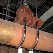
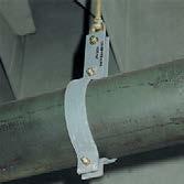
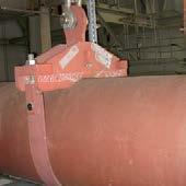
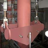
6 Product description orizontal clamps Type 41, 42, 43, 44 Type 41 Type Type 43 Type Weld-on lug 41 This is mainly used as a pipe connection for pipe systems under 80 on horizontal pipes or pipe elbows. 2.1 orizontal clamp This clamp can be used as a construction clamp or hanger clamp in cold piping systems. The field of application is limited to smaller pipe dimensions. 2.2 orizontal clamp This clamp is used for larger pipe dimensions. 3 orizontal clamp 43 This hanger clamp follows the traditional flat steel design. Its use is limited to an economical range up to an individual weight of approximately 25kg. onnection to the chain is made by bolts and ISG threaded eye nuts orizontal clamp 44 rigid yoke takes up the from a pipesurrounding U-bolt with a shim plate. From certain diameters, temperatures or ranges, a flat steel strap is used instead of a round steel U-bolt. ompletely eliminating welds, the individual components are formfitted with plug connections and bolted to each other (Patent No. D ). orizontal clamp 44 is used where 43 reaches economic limits. These are essentially the hightemperature, large pipe diameters in high ranges. onnection to the chain is made with a lug and ISG clevis 61. The connection lug is designed to accommodate connection bolts in a number of ISG s. Type Type The application range of the pipe clamps can extend over several ISG s due to the interdependency of on temperature in material properties. For this, the eye nuts are so designed that at least three corresponding bolt diameters can be accommodated. Same function reduced weight Type Pipe clamp 43 weight 27kg U-bolt 44 weight 14kg Weight reduction through 44: omparison of a ISG pipe clamp with a pipe clamp of traditional shape following the same design criteria, 32kN, temperature
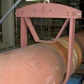
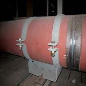
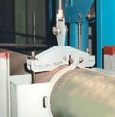
7 Product description Riser clamps Type 45, 46, Riser clamp 45 With the riser clamp 45 the lower and temperature ranges are covered. This design is particularly economical for its diameter range. Type 46, for support using 4 shear lugs welded to the pipe. Two lugs are in general used only for NW 150 and must be so arranged that they are located directly above the side section. onnection to the vertical piping is made with shear lugs welded to the pipe. The design and fitting of the lugs is the responsibility of the piping manufacturer. onnection to the chain is made with connecting bolts and ISG threaded eye nuts 60. t least 3 ISG s can be covered. When ordering, the span required (dimension ) must be specified. 2 Riser clamp 46/48 The design of this riser clamp uses the box shape for its economical use of material. The individual parts are connected without welding by means of connections, then locked to each other (Patent No. D ). onnection to the vertically arranged pipe system can be made in two different ways and so requires two different designs: Type 48, for support using trunnions welded to the pipe. The bore hole diameter for trunnions amounts to approx. 1/3 of the pipe diameter in accordance with SM ode ase N3923 and DIN N onnection to the chain is done with integrated lugs designed for connection to ISG threaded clevises 61. The connecting lugs are shaped in such a way that they can accommodate the connection bolts for several ISG s. The inner dimensions of the box, which are required for the later trunnion calculations (N dimension) can, depending on the pipe diameter OK, be taken from the table at the bottom right. Riser clamp 45 with connections Riser clamp 46 with connections Riser clamp 48 with connections Materials of pipe clamps and clamp bases clamp materials S235JR S355J2 16Mo3 13rMo4-5 21rMoV5-7 10rMo9-10 x10rmovnb9-1 horizontal clamps 41 x 42 x x x x x 43 x x x x x 44 x x x x x x x riser clamps 45 x x x x 46 x x x x x 48 x x x x x x clamp bases } x } x x x x x x Inner width of box (N-dim.) of riser clamps 46/48 pipe diameter OD 100 OD 100 OD 400 OD 400 N-Dim. OD + 12mm OD + 22mm OD + 32mm 4.4
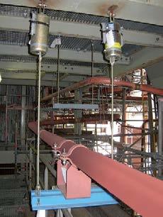
8 Product description lamp base Type 49 lamp bases are generally used as slide bearings (loose supports) for horizontally arranged pipe systems. s with pipe clamps, the application spectrum covers a diameter range from OD 21.3 to OD 1219 and a temperature range up to 600 ; for OD up to 88.9: 650. In addition to the support, the operating temperature of the pipe system is an essential criterion in the design of clamp bases; the material to be used is determined by this. The installation height is governed by the thickness of the insulation. Fixed installation heights are assigned to the temperature ranges in order to keep the number of sizes within a reasonable range. The fixed installation heights relate, for all diameters, to the respective lower rim of the pipe and change by 50mm or 100mm increments. The standard dimensions selected for the support height of the pipes, as well as the length of the slide bases, cover the majority of applications. Different applications, according to temperature and s, require different clamp base designs. If required, components with special dimensions can be supplied. small selection is shown on p. 4.9 in the section Special designs. Possible applications on a clamp base µ = friction coefficient material µ Steel / steel ~0.3 Steel / PTF ~0.1 Steel / high temperature component to 280 Steel / high temperature component from 280 to 350 ~ ~0.25 lamp base heights dependent on temperature of the medium and on pipe diameter Further information on p Temp. up to 350 Temp. up to 500 Temp. up to 560 Temp. up to 600 (650 ) Pipe Ø Pipe Ø Pipe Ø (200) 200 (250) Pipe Ø

 as a standard.")

.")

9 1 Design for low temperatures and small pipe diameters The design for this field of application consists of two omega-shaped halves. On installation with the piping the lower section is firmly bolted and forms the slide base. In the upper section the pipe is held in position by bolting. Through the free space under the pipe gained by the design of the component, constant ventilation of this area is ensured. This is essential for cold pipe systems, as otherwise pipe corrosion caused by moisture could result after only a short time. These clamp bases are electro-plated (galvanized) as a standard. 2 Design for medium and high temperatures This design consists of a shaped lower metal plate, firmly welded to two pipe clamps. The lower section is fitted, according to the respective design, with a reinforcing gusset. These clamp bases can be used in a variety of ways. y using two lower sections set against each other, a double guide can be easily produced (Fig. 2). y additionally fitting lateral guides, guidance from all sides can be provided. The shape of the base plate permits the simple mounting of lift-off restraints (Fig. 1). The lower section is so designed that it can be fitted with a stainless steel plate as a sliding surface for a slide component. See also product supplements, p Special designs If required, special lengths or heights are possible. For very large expansion displacement it might be more expedient to arrange for correspondingly long support surfaces on site. For special pipe diameters not contained in the selection tables, either corresponding intermediate sizes are supplied, or suitable inlay plates are provided for slight diameter differences. If required, double or multiple guides on the basis of standard clamp bases can be supplied (see also special designs, p. 4.9). Version 1: lamp base for low pipe temperatures , Version 2: lamp base for medium and high temperatures ,.4, xamples of use: (Fig. 1) (Fig. 2) lamp base 49 with lift-off restraint. Permissible s and dimensions, see p lamp base GP as double guide lamp base G2 as guide 4.6

.")


 or the new ISG hightemperature sliding material (up tp 350 ), reduce")

10 Product supplements for pipe clamps and clamp bases Pipe clamps and clamp bases are often equipped with supplementary parts for special applications. For this purpose ISG offers a wide variety of possibilities. 1 Stainless steel inlay plates For the support of austenitic pipe systems, all ISG pipe clamps and clamp bases can be fitted with stainless steel inlay plates of the material (X5 rni 1810). These plates must be ordered separately and are offered with the following numbers: For series 36: Stainless steel plate IP For series 37: Stainless steel plate IP For series 42: Stainless steel plate IP For series 43: Stainless steel plate IP For series 44: Stainless steel plate IP For series 45: Stainless steel plate IP For series 46/48: Stainl.st.plate 46/ IP For series /12: Stainless steel plate IP For series /14: Stainless steel plate 2x IP Material thickness: 0.5mm Type 43 with inlay plate Type 44 with inlay plate Stainless steel slide plate under clamp base 49, high temperature slide plate and spring support 29 2 Stainless steel slide plates To reduce friction resistance in clamp bases, all of them can be fitted with stainless steel sliding surfaces of the material (X5 rni 1810). These sliding surfaces, in combination with PTF slide plates 70 (up to 180 ) or the new ISG hightemperature sliding material (up tp 350 ), reduce friction forces by approx % of the support. See also section slide plates p This version of the clamp bases with slide plates must be ordered separately. For this, please add the number suffix SP : xamples: SP G2-SP The installation height of the clamp base increases by approx. 3mm. ift-off restraint 3 ift-off restraints to The clamp bases can if required be fitted with lift-off restraints. These restraints ensure that the clamp base remains in position if the support is too small or the clamp base cannot be welded on. They can be ordered according to the selection tables (p. 4.68). 4.7


 must be correspondingly selected.")


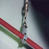
11 4 onnection plates 77 Two pipe clamps s 43 and 44 can be coupled with connection plates. This way the can be doubled. selection is shown on p When ordering, this is made clear by replacing the designation of the clamps with 77. xample 43: for clamps for clamps for clamps xample 44: for The must be specified for 44, as the upper connection ( 60) must be correspondingly selected. 5 nti-corrosion separating tape Separating tapes are used when the pairing of dissimilar materials in pipe and pipe supports must be electrically separated to prevent local corrosion. This way, the piping can be fitted with supports of more economical martensitic materials, and still be more effectively protected. The adhesive separating tapes can be applied in a temperature range from 35 to +210 and are largely resistant to acids, bases and solvents. They are applied as adhesive tape (in part multilayered) to the grease-free piping at the point where the pipe clamp body surrounds the pipe. The material thickness amounts to only 0.5mm. The tapes are supplied in different widths to suit the clamps. The order designation of 10m-lengths is: Order details: nti-corrosion separating tape Pipe guides G.. It is often necessary to limit the piping in its displacement horizontally, vertically or in both directions. On the basis of the 49 standard designs, pipe guides are offered here as a variant corresponding to the standard design in form and capacity. The order number is made up from the standard number and the desired features of the design. xample: 49 standard: double guide parallel: G2P 49 lateral guide angulated: G2 49 triple lateral guide: G3 49 foursided guide: G4 These designs can be fitted with extra slide plates. Pipe bearing ( G2P) width [mm] width [mm] b= b= b= b= b= b= b= b= b= b= b= b= b=100 onnection plates 77 on pipe clamps 43/44 4 Type G2P Type G2 Type G3 Type G4 4.8


 larger insulation thicknesses")


12 Special designs For pipe supports, the application of standardized components has long since proven itself through enormous savings in time and costs where design, shipment and installation are concerned. This applies particularly to pipe clamps and clamp bases. owever, the general complexity of pipe systems requires an extremely wide range of applications for these components, which in special cases demands the use of special designs. For the technically correct solution it is necessary in such cases to rely on experienced professionals, who can offer triedand-tested solutions and calculation processes. Special designs The standardized ISG program of pipesurrounding support components is comprehensive and covers all general cases of applications, going well beyond the usual spectrum in this field. In spite of this, more complicated cases sometimes occur where only a special design can provide the best solution. mong other things, special designs are most often called for in the following situations: unusually restricted spaces avoidance of interferences custom-made anchors exceptionally high requirements special pipe diameters especially high temperatures (up to 1000 ) larger insulation thicknesses unusual angles in piping special trunnion diameters shear lugs ISG s customers are not left alone in such situations. For these special problem cases, an experienced team of technicians and engineers is on hand, ready to react rapidly and flexibly with the right solutions. They are backed up by a range of computer software programs developed in-house. On top of this, a broad repertoire of tried-and-tested basic designs is available. There s no problem that can t be solved this conviction is powerful motivation for ISG s experts. We are happy to give our customers proof of this at any time! Special design 48 (seated) Special design 48 for an angulating pipe system Special design 38 Support for a vertical pipe section with special design ISG triple joint (special design) Special design 49 with displacement control
13 Selection of pipe clamps and clamp bases 4 The following points are important for application: 1 ll data needed for determination of the correct component and a clearly defined order are outlined in the selection tables. 2 The connection geometries are compatible with those of the ISG connection components. Due to the wide application range, connection components from several ISG s can be attached. The dimensions and geometries listed in the selection tables can vary slightly as regards design: The permissible s apply as shown. 3 The lengths of the connecting lugs are so designed that the connection points lie outside the economical insulation thicknesses. 4 ll pipe clamps and clamp bases can be fitted with corresponding stainless steel inlay plates for use with pipe systems made of austenitic materials. These components can be found on p When selecting a suitable pipe clamp the following sequence is to be followed: 5.1 Determination of the relevant page for the outer diameter (OD) of the pipe system to be supported. The normal pipe tolerances are covered. 5.2 Determination of the relevant temperature range in the column for the desired support, horizontal or vertical. 5.3 Determination of the permissible to be covered. The permissible operational taken from the selection table must not be exceeded at any time. The linear interpolation of the permissible for intermediate temperatures is allowed. 5.4 hecking of installation dimension and width for agreement with the installation conditions on site. The dimensions can be taken from the selection tables. 5.5 hecking of the span width in riser clamps ( DIM.). 5.6 Decision as to whether trunnions or shear lugs are to be used for riser clamps 46/ greement of the connection with the chain required can be checked via the ISG ranges. 5.8 Specify the component selected by entering the relevant ISG number. 6 When selecting a suitable clamp base the points should be followed. ttention must also be paid to selection of the correct height (dimension ) which depends on the thickness of the insulation. 6.1 The heights specified (dimension ) and the lengths (dimension ) are standard dimensions (see selection tables) and cover the most common cases of application. If required, the components can be supplied with different dimensions. 7 Pipe clamps and clamp bases can be supplied as special designs for unusual applications and conditions (see pp. 4.6 to 4.9 for this). 8 In the design and construction of ISG pipe clamps and clamp bases, their application in cases of increased requirements was also taken into account. In accordance with the ISG quality management system, separate manufacturing is required for this. The designation thereby changes in the 5th place by addition of a 5 (see also pp. 0.7 and 0.8 on this). The selection tables on the following pages offer an overview of the fields of application. They are classified in rising stages according to pipe diameters. ll pipe clamps and clamp bases coming into consideration for a planned pipe system can therefore be found on one page. The high-temperature range ( ) is included as a supplementary section. y coupling two pipe clamps with connection plates 77 the s can be doubled. selection can be found on p
14 OD 21.3 Temp. of medium 600 from page 4.52 oad doubling via 77, see page 4.67 Ø d 4 Pipe clamps, clamp bases, OD 21.3 (ND 15), 42, 43, 45, d D d d M eat-resistant materials, see pp. 0.9 and d d 1 d
15 OD 26.9 Pipe clamps, clamp bases, OD 26.9 (ND 20), 42, 43, 45, 49 Temp. of medium 600 from page 4.52 oad doubling via 77, see page d D Ø d d M eat-resistant materials, see pp. 0.9 and d d d d
16 OD 33.7 Temp. of medium 600 from page 4.52 oad doubling via 77, see page 4.67 Ø d 4 Pipe clamps, clamp bases, OD 33.7 (ND 25), 42, 43, 45, d D d d M eat-resistant materials, see pp. 0.9 and d d 1 d
17 OD 42.4 Pipe clamps, clamp bases, OD 42.4 (ND 32), 42, 43, 45, 49 Temp. of medium 600 from page 4.52 oad doubling via 77, see page d D Ø d d M eat-resistant materials, see pp. 0.9 and d d d D D D D d
18 OD 48.3 Temp. of medium 600 from page 4.52 oad doubling via 77, see page 4.67 Ø d 4 Pipe clamps, clamp bases, OD 48.3 (ND 40), 42, 43, 45, d D d M eat-resistant materials, see pp. 0.9 and d 1 d d 1 d D D D D
19 OD 60.3 Pipe clamps, clamp bases, OD 60.3 (ND 50), 42, 43, 45, 49 Temp. of medium 600 from page 4.52 oad doubling via 77, see page d D Ø d d M eat-resistant materials, see pp. 0.9 and d d d D D D D d
20 OD 73 Temp. of medium 600 from page 4.52 oad doubling via 77, see page 4.67 Ø d 4 Pipe clamps, clamp bases, OD 73 (ND 65), 42, 43, 45, 46, 48, d d M eat-resistant materials, see pp. 0.9 and 4.4 d d d 1 K d D D D D R min max K [kg min] [kg max] R [kg min] [kg max]
21 OD 76.1 Temp. of medium 600 from page 4.52 oad doubling via 77, see page 4.67 Pipe clamps, clamp bases, OD 76.1 (ND 65), 42, 43, 45, 46, 48, d Ø d d M eat-resistant materials, see pp. 0.9 and d d d D D D D d 1 K min max K [kg min] [kg max] R [kg min] [kg max] R
22 OD 88.9 Temp. of medium 600 from page 4.52 oad doubling via 77, see page 4.67 Ø d 4 Pipe clamps, clamp bases, OD 88.9 (ND 80), 42, 43, 45, 46, 48, d d M eat-resistant materials, see pp. 0.9 and 4.4 d d D D d 1 K d D D D D min max K [kg min] [kg max] R [kg min] [kg max] 36 R
23 OD 108 Pipe clamps, clamp bases, OD 108 (ND 100), 42, 43, 45, 46, 48, 49 Temp. of medium 600 from page 4.52 oad doubling via 77, see page d M eat-resistant materials, see pp. 0.9 and d D D D d d 1 d D D D D min max K [kg min] [kg max] R [kg min] [kg max] K R
24 OD Temp. of medium 600 from page 4.52 oad doubling via 77, see page 4.67 Pipe clamps, clamp bases, OD (ND 100), 42, 43, 45, 46, 48, d M eat-resistant materials, see pp. 0.9 and 4.4 d d D D D d d D D D D K R min max K [kg min] [kg max] R [kg min] [kg max]
25 OD 133 Pipe clamps, clamp bases, OD 133 (ND 125), 42, 43, 45, 46, 48, 49 Temp. of medium 600 from page 4.52 oad doubling via 77, see page d M eat-resistant materials, see pp. 0.9 and d D D D D d d D D D D d min max K [kg min] [kg max] R [kg min] [kg max] K 51 R
26 OD Pipe clamps, clamp bases, OD (ND 125), 42, 43, 45, 46, 48, d M eat-resistant materials, see pp. 0.9 and d 1 d D D D D d 1 46 d D D D D min max K [kg min] [kg max] R [kg min] [kg max] K 51 R
27 OD 159 Pipe clamps, clamp bases, OD 159 (ND 150), 42, 43, 46, 48, 49 Temp. of medium 600 from page 4.52 oad doubling via 77, see page d M eat-resistant materials, see pp. 0.9 and d D D D D d min max K [kg min] [kg max] R [kg min] [kg max] K 63 R
28 OD Pipe clamps, clamp bases, OD (ND 150), 42, 43, 46, 48, d M eat-resistant materials, see pp. 0.9 and 4.4 d d D D D D K min max K [kg min] [kg max] R [kg min] [kg max] R
29 OD Pipe clamps, clamp bases, OD (ND 175), 42, 43, 46, 48, 49 Temp. of medium 600 from page 4.52 oad doubling via 77, see page d M eat-resistant materials, see pp. 0.9 and d D D d min max K [kg min] [kg max] R [kg min] [kg max] K R
30 OD Pipe clamps, clamp bases, OD (ND 200), 42, 43, 44, 46, 48, d M eat-resistant materials, see pp. 0.9 and 4.4 d d D D d K R min max K [kg min] [kg max] R [kg min] [kg max]
31 OD Pipe clamps, clamp bases, OD (ND 225), 42, 43, 44, 46, 48, 49 Temp. of medium 600 from page 4.52 oad doubling via 77, see page d M eat-resistant materials, see pp. 0.9 and d D D d d min max K [kg min] [kg max] R [kg min] [kg max] K R
32 OD 267 Pipe clamps, clamp bases, OD 267 (ND 250), 42, 43, 44, 46, 48, d M eat-resistant materials, see pp. 0.9 and 4.4 d d d K R min max K [kg min] [kg max] R [kg min] [kg max]
33 OD 273 Pipe clamps, clamp bases, OD 273 (ND 250), 42, 43, 44, 46, 48, 49 Temp. of medium 600 from page 4.52 oad doubling via 77, see page d M eat-resistant materials, see pp. 0.9 and d d d min max K [kg min] [kg max] R [kg min] [kg max] K R
34 OD Temp. of medium 600 from page 4.52 oad doubling via 77, see page 4.67 Pipe clamps, clamp bases, OD (ND 300), 42, 43, 44, 46, 48, d M eat-resistant materials, see pp. 0.9 and d 1 d d K R min max K [kg min] [kg max] R [kg min] [kg max]
35 OD Pipe clamps, clamp bases, OD (ND 350), 42, 43, 44, 46, 48, 49 Temp. of medium 600 from page 4.52 oad doubling via 77, see page d M eat-resistant materials, see pp. 0.9 and d d d min max K [kg min] [kg max] R [kg min] [kg max] K R
36 OD 368 Pipe clamps, clamp bases, OD 368 (ND 350), 42, 43, 44, 46, 48, d M eat-resistant materials, see pp. 0.9 and d 1 d d K R min max K [kg min] [kg max] R [kg min] [kg max]
37 OD Pipe clamps, clamp bases, OD (ND 400), 42, 43, 44, 46, 48, 49 Temp. of medium 600 from page 4.52 oad doubling via 77, see page d M eat-resistant materials, see pp. 0.9 and d d d min max K [kg min] [kg max] R [kg min] [kg max] K R
38 OD 419 Pipe clamps, clamp bases, OD 419 (ND 400), 42, 43, 44, 46, 48, d M eat-resistant materials, see pp. 0.9 and d 1 d d K R min max K [kg min] [kg max] R [kg min] [kg max]
39 OD Pipe clamps, clamp bases, OD (ND 450), 42, 43, 44, 46, 48, 49 Temp. of medium 600 from page 4.52 oad doubling via 77, see page d M eat-resistant materials, see pp. 0.9 and d d d min max K [kg min] [kg max] R [kg min] [kg max] K R
40 OD 508 Pipe clamps, clamp bases, OD 508 (ND 500), 42, 44, 46, 48, d M eat-resistant materials, see pp. 0.9 and 4.4 d K R min max K [kg min] [kg max] R [kg min] [kg max]
41 OD Pipe clamps, clamp bases, OD (ND 550), 42, 44, 46, 48, 49 Temp. of medium 600 from page 4.52 oad doubling via 77, see page d M eat-resistant materials, see pp. 0.9 and d min max K [kg min] [kg max] R [kg min] [kg max] K R
42 OD Pipe clamps, clamp bases, OD (ND 600), 42, 44, 46, 48, d M eat-resistant materials, see pp. 0.9 and 4.4 d K R min max K [kg min] [kg max] R [kg min] [kg max]
43 OD Temp. of medium 600 from page 4.52 oad doubling via 77, see page 4.67 Pipe clamps, clamp bases, OD (ND 650), 42, 44, 46, 48, d M eat-resistant materials, see pp. 0.9 and 4.4 d min max K [kg min] [kg max] R [kg min] [kg max] K R
44 OD Pipe clamps, clamp bases, OD (ND 700), 42, 44, 46, 48, d M eat-resistant materials, see pp. 0.9 and 4.4 d K R min max K [kg min] [kg max] R [kg min] [kg max]
45 OD 762 Temp. of medium 600 from page 4.52 oad doubling via 77, see page 4.67 Pipe clamps, clamp bases, OD 762 (ND 750), 42, 44, 46, 48, d M eat-resistant materials, see pp. 0.9 and 4.4 d min max K [kg min] [kg max] R [kg min] [kg max] K R 4.42
46 OD Pipe clamps, clamp bases, OD (ND 800), 42, 44, 46, 48, d M eat-resistant materials, see pp. 0.9 and 4.4 d K R min max K [kg min] [kg max] R [kg min] [kg max]
47 OD Temp. of medium 600 from page 4.52 oad doubling via 77, see page 4.67 Pipe clamps, clamp bases, OD (ND 850), 42, 44, 46, 48, d M eat-resistant materials, see pp. 0.9 and 4.4 d min max K [kg min] [kg max] R [kg min] [kg max] K R
48 OD Pipe clamps, clamp bases, OD (ND 900), 42, 44, 46, 48, d M eat-resistant materials, see pp. 0.9 and 4.4 d K R min max K [kg min] [kg max] R [kg min] [kg max]
49 OD Temp. of medium 600 from page 4.52 oad doubling via 77, see page 4.67 Pipe clamps, clamp bases, OD (ND 950), 42, 44, 46, 48, d M eat-resistant materials, see pp. 0.9 and 4.4 d min max K [kg min] [kg max] R [kg min] [kg max] K R 4.46
50 OD 1016 Pipe clamps, clamp bases, OD 1016 (ND 1000), 42, 44, 46, 48, d 2 42 T M eat-resistant materials, see pp. 0.9 and 4.4 d T T T T T T T T T T T T T T T T T T T T K R min max K [kg min] [kg max] R [kg min] [kg max] 4. T T T T T T T T T T T T T T T T T T T T T T T T T T T T T T T
51 OD 1067 Pipe clamps, clamp bases, OD 1067 (ND 1050), 42, 44, 46, 48, d 2 42 T M T T T T T T T T T T T T T T T T T T T T eat-resistant materials, see pp. 0.9 and 4.4 d min max K [kg min] [kg max] R [kg min] [kg max] 4. T T T T T T T T T T T T T T T T T T T T T T T T T T T T T T T K R 4.48
52 OD 1118 Pipe clamps, clamp bases, OD 1118 (ND 1100), 42, 44, 46, 48, d 2 42 T M eat-resistant materials, see pp. 0.9 and 4.4 d T T T T T T T T T T T T T T T T T T T T K R min max K [kg min] [kg max] R [kg min] [kg max] 4. T T T T T T T T T T T T T T T T T T T T T T T T T T T T T T T
53 OD 1168 Temp. of medium 600 from page 4.52 oad doubling via 77, see page 4.67 Pipe clamps, clamp bases, OD 1168 (ND 1150), 42, 44, 46, 48, d 2 42 T M T T T T T T T T T T T T T T T T T T T T eat-resistant materials, see pp. 0.9 and 4.4 d min max K [kg min] [kg max] R [kg min] [kg max] 4. T T T T T T T T T T T T T T T T T T T T T T T T T T K R T T T T T
54 OD 1219 Pipe clamps, clamp bases, OD 1219 (ND 1200), 42, 44, 46, 48, d 2 42 T M eat-resistant materials, see pp. 0.9 and 4.4 d T T T T T T T T T T T T T T T T T T T T K R min max K [kg min] [kg max] R [kg min] [kg max] 4. T T T T T T T T T T T T T T T T T T T T T T T T T T T T T T T
55 OD Temperatures Pipe clamps, clamp bases, OD 21.3 (ND 15), 45, d Pipe clamps, clamp bases, OD 26.9 (ND 20), 45, d d1 Pipe clamps, clamp bases, OD 33.7 (ND 25), 43, 45, d d Pipe clamps, clamp bases, OD 42.4 (ND 32), 43, 45, d d d
56 OD Temperatures Pipe clamps, clamp bases, OD 48.3 (ND 40), 43, 45, d d d d 1 48 d N R Pipe clamps, clamp bases, OD 60.3 (ND 50), 43, 45, d d Pipe clamps, clamp bases, OD 73 (ND 65), 43, 48, d d N R min max min max
57 OD Temperatures Pipe clamps, clamp bases, OD 76.1 (ND 65), 43, 48, d d N R min max min max Pipe clamps, clamp bases, OD 88.9 (ND 80), 43, 48, d d N R min max min max Pipe clamps, OD 108 (ND 100), 43, d d N R min max min max d1 48 d N R Pipe clamps, OD (ND 100), 43, d d N R min max min max Pipe clamps, OD 133 (ND 125), 43, d d N R min max min max
58 OD Temperatures Pipe clamps, OD (ND 125), 43, d d d N R min max min max Pipe clamps, OD 159 (ND 150), 43, d d N R min max min max Pipe clamps, OD (ND 150), 43, d dn R min max min max Pipe clamps, OD (ND 175), 43, d d N R min max min max d N R Pipe clamps, OD (ND 200), 44, 48 max insul d N R min max min max
59 OD Temperatures Pipe clamps, OD (ND 225), 44, 48 max max insul d N R min max min max Pipe clamps, OD 267 (ND 250), 44, 48 max max insul d N R min max min max Pipe clamps, OD 273 (ND 250), 44, 48 max max insul d N R min max min max d N R Pipe clamps, OD (ND 300), 44, 48 max max insul d N R min max min max
60 OD Temperatures Pipe clamps, OD (ND 350), 44, 48 max max insul d N R min max min max Pipe clamps, OD 368 (ND 350), 44, 48 max max insul d N R min max min max d N R Pipe clamps, OD (ND 400), 44, 48 max max insul d N R min max min max
61 OD Temperatures Pipe clamps, OD 419 (ND 400), 44, 48 max max insul d N R min max min max Pipe clamps, OD (ND 450), 44, 48 max max insul d N R min max min max Pipe clamps, OD 508 (ND 500), 44, 48 max max insul d N R min max min max d N R 4.58
62 OD Temperatures Pipe clamps, OD (ND 550), 44, 48 max max insul d N R min max min max Pipe clamps, OD (ND 600), 44, 48 max max insul d N R min max min max d N R Pipe clamps, OD (ND 650), 44, 48 max max insul d N R min max min max
63 OD Temperatures Pipe clamps, OD (ND 700), 44, 48 max max insul d N R min max min max Pipe clamps, OD 762 (ND 750), 44, 48 max max insul d N R min max min max Pipe clamps, OD (ND 800), 44, 48 max max insul d N R min max min max d N R 4.60
64 OD Temperatures Pipe clamps, OD (ND 850), 44, 48 max max insul d N R min max min max Pipe clamps, OD (ND 900), 44, 48 max max insul d N R d N R min max min max Pipe clamps, OD (ND 950), 44, 48 max max insul d N R min max min max
65 OD Temperatures Pipe clamps, OD 1016 (ND 1000), 44, 48 max max insul. 44 T T T T T T T d N R min max min max 48 T T T T T T T Pipe clamps, OD 1067 (ND 1050), 44, 48 max max insul. 44 T T T T T T T d N R min max min max 48 T T T T T T T Pipe clamps, OD 1118 (ND 1100), 44, 48 max max insul. 44 T T T T T T T d N R min max min max 48 T T T T T T T d N R 4.62
66 OD Temperatures Pipe clamps, OD 1168 (ND 1150), 44, 48 max max insul. 44 T T T T T T T d N R min max min max 48 T T T T T T T Pipe clamps, OD 1219 (ND 1200), 44, 48 max max insul. 44 T T T T T T T d N R d N R min max min max 48 T T T T T T T


67 U-bolts Type 40 4 OD U-bolts to Type 40 mainly serves to fasten warm pipe systems of max. 80 to existing steel structures. Ø d 2 OD d 2 x weight M6 x M6 x M6 x M10 x M10 x M10 x M12 x M12 x M12 x M12 x M12 x M12 x M16 x M16 x M20 x M20 x M20 x M20 x M24 x M24 x M24 x M24 x M24 x M24 x th digit: 1 = S235JR 3 = X5rNi18-10 Order details: Scope of delivery: incl. 4 nuts 4.64
68 Weld-on lugs for pipes Type 41 Weld-on lugs for pipes 49 D9 11 to t Permissible at 80 = normal operating conditions ( case ) of the corresponding (3rd place in the designation, see Max. permissible for static components, p. 0.6). G Ø R xisting stress in the specified weld seam 50 N/mm 2 at 4 angled tension. OD s max Material: S235JR s max = 10mm s max = 100mm Ø R G t a weight 41 D D Reduction factors of permissible at increased temperatures: T F perm. (T) F perm. (80 ) F perm. (80 ) Order details: weld-on lugs for pipes
69 Weld-on lugs for pipe elbows Type 41 S max = 10mm weight a S max = 100mm weight a Permissible s at 80 = normal operating conditions ( case ) of the specified in each case (see Max. permissible for static components, p. 0.6). OD R 1 t Stress existing in the specified weld seam 50 N/mm 2 at 4 angled tension. 4 Weld-on lugs for pipe elbows (R 1.5 OD) to s max t Ø R Reduction factors of permissible at increased temperatures: T F perm. (T) F perm. (80 ) F perm. (80 ) Order details: weld-on lug for pipe elbows R 1.5 OD R OD s max =10mm s max =100mm 4.66
70 onnection plates Type 77 onnection plates for coupling pipe clamps to y coupling 2 pipe clamps with 77 the s can be doubled. Order details: connection plate for clamps to D to to weight onnection plates for coupling pipe clamp 44 up to 600 d to 77 T4.. Type designation of the connection plates: the figures 44 of the clamps to be coupled must be replaced by the figures 77. xample: connection plate for d 1 min max max weight to to to to to to 77 T The for the upper connection ( 60) must be stated when ordering. Order details: connection plate


71 ift-off restraints for clamp bases Type 49 4 ift-off restraints for clamp base to t for clamp bases t /pair to to to to to to to to to to to to to to 49 T The following shortduration lift-off s are permissible for the clamp bases: to % to 49 T4.. 7% of the catalog. Order details: lift-off restraint On request special lift-off restraints for SP can be delivered. 4.68
72 Installation and operating instructions Type 42, 43, 44, 45, 46, 48 Type Type Type 43 Type 44 U-bolt design 1 Transport and storage are must be taken during transport that none of the clamp components is damaged. When stored in the open the clamps must be protected from dirt and water. 2 Delivery condition ISG pipe clamps are delivered ready for installation, with all the necessary bolts. For reason of more effective dispatch clamps can be supplied partially assembled. 3 Installation 3.1 orizontal clamp Type 42 This clamp is used as a horizontal clamp in connection with threaded eye nut 60. When tightening the bolts, care must be taken that the clamp halves are parallel to each other. The bolts are to be secured with lock nuts. Type 43 onnection is made with this horizontal clamp via a separate connection bolt with a threaded eye nut 60. The bolts must be secured with the cotter pins provided; otherwise proceed as with 42. Type 44, U-bolt/ strap for temperatures up to 600 These clamps consist of an upper section with a connecting lug and, depending on and temperature range, a U-bolt with an inlay plate or a flat steel strap as lower section. For installation, remove the pre-assembled lower part by loosening the locking nuts or removing the connection bolts. The upper section is seated on the piping and the lower one inserted and held by tightening the U-bolt or flat steel strap. fter alignment of the clamp the bolts are to be firmly tightened. The U-bolts are secured with lock nuts and the flat steel straps with tab washers under the hexagon nuts. Type 44 for temperatures over 600 These clamps consist of an upper section with a connection lug and restrainer and a flat steel strap as lower part. For installation the restraint and strap must be taken off by removing the outer threaded pins and the connection bolts. fter attaching the upper section to the hanging part the restraint and strap can be reconnected. They are then bolted on and the threaded pins fitted. ll parts must then be firmly screwed on. Installation of 44 for temperatures over Riser clamps Type 45 When installing these clamps care must be taken to place the spacers supplied onto the bolts between the clamp halves. The bolts are then tightened and locked. The clamp is hung up via the outer support bolts, which are secured with washers and cotter pins. The specified height of the clamp is set by tightening the suspended parts and creating a force-and formfitting connection with the shear lugs. Riser clamp 45 with connection components Type 44 strap design 4.69
73 Type 46 This riser clamp is supplied in single parts sealed in plastic shrink wrap. For installation it is best to first fit the front plates into the suspended parts. These parts should be tightened at the lowest level, then both side plates can be attached one after another. In the case of large clamps, the opp o site side must hereby be temporarily propped up. For installation, both side plates are seated on the trunnions and connected with the threaded pins. The nuts should be only loosely tightened here. For large clamps the components should be temporarily propped up. The front plates can now be pushed from below into the intake slots and connected to the suspended parts. The connection points between front and side plates are made by aligning and firmly tightening the pre-assembled locking plates. The specified height of the clamp is set by tightening the suspended parts, creating a force-and-formfitting connection with the trunnions. Riser clamp 46 with connection components 4 Riser clamp 48 with connection components Type 46 fter that, the top plates for the shear lugs are inserted and bolted on. The connection points between front and side plates are secured by aligning and firmly tightening the pre-assembled locking plates. The specified height is set by tightening the suspended parts, creating a forceand formfitting connection with the shear lugs. Type 48 4 Inspection and maintenance The horizontal clamp functions flawlessly in any operating condition if the secured boltings are free of any play. Under normal operating conditions maintenance is not required. Type 48 This riser clamp is supplied in single parts sealed in shrink wrap. First of all, a side plate should be prepared by attaching the thread ed pins. 4.70


74 Installation and operating instructions Type 49 lamp bases lamp bases for smaller pipe diameters , lamp bases for larger pipe diameters ,...4, Transport and storage are must be taken during transport that no clamp base components are damaged. When stored in the open, the clamp bases must be protected from dirt and water. 2 Delivery condition If not agreed otherwise, ISG clamp bases are delivered pre-assembled and ready for installation. For reasons of efficient dispatch clamp bases can be delivered partially assembled. In any event the clamp base is supplied with all the necessary bolts. 3 Installation Type 49 ISG clamp bases are slidable supports that are fastened to pipe systems by clamping tension. On installation it is essential that the whole clamp base bottom lies flush and can slide unobstructed over the given stretches. If required, the lower parts can be welded to the supporting surface. Different designs are used depending on the height of the support bearing, the pipe diameter, the support and the operating temperature. The following points are hereby to be observed: 4 Inspection and maintenance Under normal circumstances no maintenance is required. Type and Type , 4 lamp base 49 with slide plate Type and This clamp base design is made up of two halves to be fitted to each side of the pipe. The cornered surfaces form the base. In this lower part the clamp base halves are firmly bolted to each other. The upper bolting serves for clamping tension in the piping against slipping. Type , and The foot of the clamp base forms a firm support for the pipe to be laid in. The upper half provides clamping tension and is to be firmly bolted. Type , 4,
Spring hangers, spring supports
 Spring hangers, spring supports 2 spring Spring hangers, supports PRODUCT 2 GROUP Spring hangers, spring supports Contents Page Field of application...2.1 Overview of spring hangers and spring supports...2.3
SPRING HANGERS, SPRING SUPPORTS PRODUCT GROUP
 SPRING HANGERS, SPRING SUPPORTS PRODUCT GROUP VARIABLE SPRING ELEMENTS CONTENTS PAGE 0 Spring hangers, spring supports, sway braces.1 Load table for spring hangers, spring supports and other spring elements.3
ORDERING: Specify size, figure number, description, nominal pipe size or special O.D. and C-to-C dimension. C - C LOAD lb.
 Fig. 2110 www.pipingtech.com/fig2110 Sway Strut with 4 of Adjustment Engineered spring supports option 1 option 2 ORDERING: Specify size, figure number, description, nominal pipe size or special O.D. and
Shaft-Hub-Connections
 Stand: 14.01.2010 Shaft-Hub-Connections Shrink Discs Cone Clamping Elements Star Discs 36 Edition 2012/2013 RINGSPANN Eingetragenes Warenzeichen der RINGSPANN GmbH, Bad Homburg Table of Contents Introduction
SECTION PIPE HANGERS AND SUPPORTS
 Part I - GENERAL 1.01 SECTION INCLUDES A. The work covered under this section consists of the furnishing of all necessary labor, supervision, materials, equipment, and services to completely execute the
Ball Rail Systems RE / The Drive & Control Company
 Ball Rail Systems RE 82 202/2002-12 The Drive & Control Company Rexroth Linear Motion Technology Ball Rail Systems Roller Rail Systems Standard Ball Rail Systems Super Ball Rail Systems Ball Rail Systems
Rodless Pneumatic Cylinders Series OSP-P
 Rodless Pneumatic Cylinders Series OSP-P System Concepts & Components... 2-5 Technical Data... 7-9 Dimensions... 10-15 Active rakes... 16-19 Accessories (Mounts & Supports)... 20-29 Ordering Information...30
Connection technology for Linear Motion Systems 1.3
 Connection technology for Linear Motion Systems 1.3 2 Connection technology for Linear Motion Systems 1.3 Connection technology for Linear Motion Systems 1.3 3 Contents 4 Combination options for -Z linear
Model R. q Fig. 81-H: Standard Type: q A, q B, q C, q D, q E, q F. q Fig. C-81-H: Corrosion Resistant CONSTANT SUPPORTS.
 OSA SUPPORS odel R q Fig. 81-: Standard : q A, q, q, q, q, q F q Fig. -81-: orrosion Resistant : q A, q, q, q, q, q F onstant Support Finish: Standard finish; painted with semi gloss primer. orrosion resistant;
tensioning systems 107
 Tensioning systems 107 TENSIONING SYSTEMS TABLE OF CONTENTS Table of Contents 108 Introduction 109 Function, Principles, Handling 110 Optical Control Displays 111 Spann-Box Overview 112 113 Signs and Symbols
Chain and Belt Tensioning Systems
 Chain and Belt Tensioning Systems Chain and Belt Tensioning Systems 121 TENSIONING SYSTEMS TABLE OF CONTENTS Introduction 123 Function, Principles, Handling 124 Optical Control Displays 125 Chain and Belt
ARMA BAĞLANTI SİSTEMLERİ A.Ş.
 ARMA BAĞLANTI SİSTEMLERİ A.Ş. ARMA FIXING SYSTEMS, initially established as a molding workshop in 1980, is an innovative and dynamic company serving its customers in various sectors primarily automotive,
KLINGERSIL C High stress capability due to metal mesh reinforcement. C-4438 KLINGERSIL
 KLINGERSIL C-44 metal mesh reinforcement KLINGERSIL C-44 Synthetic fibres and glass fibres, bonded with NBR. metal mesh. Resistant to oils, hydrocarbons, water and steam. A universal material with outstanding
Heavy-Duty Rod Ends - Male with integral spherical plain bearing
 Heavy-Duty Rod Ends - Male with integral spherical plain bearing 65700 Order No. Thread (hand) d 1 l 1 d 2 d 3 d 4 l 2 l 3 X g H7 65700.W0005 Right 5 33 M 5 11,11 18 20 9 14 65700.W0006 Right 6 36 M 6
STRUCTURAL ATTACHMENT ELEMENTS
 STRUCTURAL ATTACHMENT ELEMENTS 7 PRODUCT GROUP 7 STRUCTURAL ATTACHMENTS, TRAPEZES CONTENTS PAGE 0 Structural attachments, trapezes 7.1 Weld-on clevis type 73 7.2 Weld-on eye plate type 75 7.2 Weld-on
Rexnord Tollok Locking Assemblies
 Tollok Catalog Download the most up-to-date version at www.rexnord.com/documentation Rexnord Tollok Locking Assemblies Why Choose Rexnord Tollok Locking Assemblies? Why Choose Rexnord? When it comes to
NSK Linear Guides. Roller Guide RA Series. Extended series
 NSK Linear Guides A roller guide series employing advanced analysis technology offers super-high load capacity and rigidity. The RA series includes a complete lineup to handle a wide range of applications.
ORIGA Pneumatic Linear Drives OSP-L
 ORIGA Pneumatic Linear Drives OSP-L Very long lifetime and lowest leakage A NEW Modular Linear Drive System With this second generation linear drive Parker Origa offers design engineers complete flexibility.
SUSPENSION 04 CLAMPS
 SUSPENSION CLAMPS 04 4 SUSPENSION CLAMPS 57 Contents General... 58 Suspension clamp trunnion type, forged,... 63 Suspension clamp trunnion type, forged, with bigger angle of deflection, for aluminium based
National Enduralube Bearings
 Bearings The Worlds Most Reliable Bronze Bearing w w w. n ationalbronze.com National Bronze Mfg. Co. 800-875-3558 (Toll Free) 586-791-9044 (Fax) INTRODUCTION Since 1911 National Bronze Mfg. Co. has been
Technical Description Edition 2007 Mounting, maintenance and repair of propshafts with flanged universal joints
 Technical Description Edition 2007 Mounting, maintenance and repair of propshafts with flanged universal joints 1. Recommendations Assembly, disassembly, maintenance and repair of propshafts should be
T95 Load Cell Assembly for Silo, Tank & Vessel Weighing and Axle Weighing
 T95 Load Cell Assembly for Silo, Tank & Vessel Weighing and Axle Weighing Capacities 2t to 20t Stainless Steel Load Sensor OIML C3 approved Integrated Lift Off Prevention Load cell is always in Tension
LCMass Series Mass Flow Sensor
 LCMass 100-140 Series Mass Flow Sensor Technical Data Sheet HIGH ACCURACY The LCMass 100 achieves a ±0.15% accuracy on liquids. COMPACT ECONOMIC DESIGN Straight twin-tube design allows for an overall smaller
Roller chain idler sprocket units Idler pulley units
 Roller chain idler sprocket units Idler pulley units Roller chain idler sprocket units, idler pulley units Page Product overview Roller chain idler sprocket units, idler pulley units... 334 Design and
RE / STAR Tolerance Rings STAR Ball Knobs, Knob and Lever Type Handles
 RE 2 970/.99 STAR Tolerance Rings STAR Ball Knobs, Knob and Lever Type Handles STAR Tolerance Rings Product Overview Tolerance rings are made of hard, embossed spring steel strip and belong to the class
PSI Plastic Insulators System
 Pipeline Accessories PSI Plastic Insulators System General Information Technical Data Selection Guide 1 PSI Plastic Insulators System Material Test Certificate PSI Plastic Insulators System General Information
Victory A-Series Actuators PRODUCT CATALOG V55A V43A FG1 V32A FG2 V26A
 Victory -Series ctuators PROUT TLOG V55 with parallel motor mounting V4 G1 with parallel motor mounting V2 G2 with inline motor mounting V26 with inline motor mounting Longer, aster, and More Reliable
EMC-HD. C 01_2 Subheadline_15pt/7.2mm
 C Electromechanical 01_1 Headline_36pt/14.4mm Cylinder EMC-HD C 01_2 Subheadline_15pt/7.2mm 2 Elektromechanischer Zylinder EMC-HD Short product name Example: EMC 085 HD 1 System = ElectroMechanical Cylinder
10 Thrust ball bearings
 10 Thrust ball bearings Designs and variants.............. 1010 Single direction thrust ball bearings... 1010 Double direction thrust ball bearings.. 1010 Cages............................ 1010 Bearings
ND DYNAMOC .STATIC STR INTS BERGEN-PATERSON PIPESUPPORT CORPORATION DESIGN INFORMATION WOBURN, MASSACHUSETTS 01888
 CATALOG 82 ENGINEERING SUPPLEMENT NO.3.STATIC ND DYNAMOC STR INTS DESIGN INFORMATION BERGEN-PATERSON PIPESUPPORT CORPORATION WOBURN, MASSACHUSETTS 01888 Bergen-Paterson markets the widest selection of
smart mounting smart tools Mounting Tools Dismounting Tools Induction Heaters
 smart tools smart mounting Mounting Tools Dismounting Tools Induction Heaters Content Mounting Tools Dismounting Tools 4-5 Fitting Tool FT 33 6 Maintenance Kit MK 10-30 7 Ball Bearing Puller BP 61 8 Seal
XB IEC Terminal Blocks. Screw Type Insulation Displacement Connection Type
 XB IEC Terminal Blocks Screw Type Spring Cage Type Insulation Displacement Connection Type 2 XB IEC Terminal Blocks. Versatility, quality, and reliability. Sometimes it s the little things Eaton knows
SLEWING RING CHARACTERISTICS, APPLICATIONS
 SLEWING RING CHARACTERISTICS, APPLICATIONS Slewing rings are large-sized bearings which are able to accommodate combined load, i.e. axial, radial loads and tilting moment. They are usually provided with
Industrial Horizontal Bearings IH and HD Series
 Industrial Horizontal Bearings IH and HD Series 2 3 About Us As the inventor of the hydrodynamic bearing over 100 years ago, Michell Bearings has continued to develop its products to meet the changing
ABB life cycle services Uninterruptible power supplies
 ABB life cycle services Uninterruptible power supplies 2 ABB Life cycle brochure UPS service portfolio Life cycle services for uninterruptible power supplies As your service partner, ABB guarantees you
White paper: Pneumatics or electrics important criteria when choosing technology
 White paper: Pneumatics or electrics important criteria when choosing technology The requirements for modern production plants are becoming increasingly complex. It is therefore essential that the drive
1 Variable spring supports Design Instructions
 Design Instructions 1.1 Application Rigid supporting structures are not capable to accommodate vertical displacement or large horizontal forced travels of piping. This nodes should be supported by spring
JOINTING OF LARGE BORE PE PIPES: THINK BIG AND EVEN BIGGER!
 JOINTING OF LARGE BORE PE PIPES: THINK BIG AND EVEN BIGGER! Robert Eckert FRIATEC AG, Germany Abstract A New Generation of Electrofusion: A technical comparison between the new wedge coupler and the traditional
Study on Braking Energy Recovery of Four Wheel Drive Electric Vehicle Based on Driving Intention Recognition
 Open Access Library Journal 2018, Volume 5, e4295 ISSN Online: 2333-9721 ISSN Print: 2333-9705 Study on Braking Energy Recovery of Four Wheel Drive Electric Vehicle Based on Driving Intention Recognition
For advanced drive technology CLAMPEX. Shaft-hub-connection. KTR Precision joints CLAMPEX
 technology CLAMPEX Shaft-hub-connection CLAMPEX KTR Precision joints 227 technology Table of contents Page Brief information 228 Selection and calculation 25-255 CLAMPEX -Selection Shaft diameter = d 0
Shrink Discs, Smart-Lock & Shaft Couplings
 RINGFEDER Products are available from MARYLAND METRICS Shrink Discs, Smart-Lock & Shaft Couplings US 08 2009 Partner for performance RINGFEDER Products are available from MARYLAND METRICS P.O. Box 261
Flanged housings FNL series
 Flanged housings FNL series Bearing types Self-aligning ball bearings Spherical roller bearings CARB toroidal roller bearings Bearing dimension series 02, 22 FNL flanged housings are well-proven machine
 DRUM BRAKE RIMS Periodic inspection of drum brake rims is necessary to determine indications of uneven or excessive wear. In general, brake rim failures other that regular wear are caused by brake linings
Set screw mounted ball bearings
 Features/Benefits For over 70 years, Dodge has been talking to mounted bearing users and listening to their needs. This experience lead to the design of the optimum mounted ball bearing. A state-of-the-art
Air Spring Systems. Air actuators for pneumatic applications
 Air Spring Systems Air actuators for pneumatic applications Air actuators for pneumatic applications ContiTech air actuators are all-round talents. With a broad product range of C, D, R, and S model series
Bearings. Rolling-contact Bearings
 Bearings A bearing is a mechanical element that limits relative motion to only the desired motion and at the same time it reduces the frictional resistance to the desired motion. Depending on the design
Mounting Overlap Shield. Face Clamps. Gap. Seat Depth. Lead In Chamfer. Loose Fit.
 Mounting Introduction: Reali-Slim thin section ball bearings have a crosssection thickness that is much thinner than standard bearings of the same diameter, and are therefore more sensitive to shaft and
Standard Supports 2020
 Standard Supports 2020 Standard Supports 2020 dition: September 2016 The LISG product program covers all components required for the implementation of modern concepts in the support of pipe systems. These
Is Low Friction Efficient?
 Is Low Friction Efficient? Assessment of Bearing Concepts During the Design Phase Dipl.-Wirtsch.-Ing. Mark Dudziak; Schaeffler Trading (Shanghai) Co. Ltd., Shanghai, China Dipl.-Ing. (TH) Andreas Krome,
Why Alignment. Reliability starts with precision shaft alignment. Up to 50% of damage to rotating machinery is directly related to misalignment!
 Why Alignment Reliability starts with precision shaft alignment Up to 50% of damage to rotating machinery is directly related to misalignment! Well aligned machines reduce operating costs! Reliability
YRTC and YRTCMA Rotary Axis Bearings with Absolute Value Angular Measuring System. Increased productivity with very high operational reliability
 YRTC and YRTCMA Rotary Axis Bearings with Absolute Value Angular Measuring System Increased productivity with very high operational reliability Increased productivity with very high operational reliability
High torque stainless steel motors ADVANCED LINE. Stainless Steel Air Motors from 20 W / 0.03 Hp up to 1.2 kw / 1.6 Hp
 Screwdriving technology Automation Air motors Air tools ADVANCED LINE Stainless Steel Air s from 20 W / 0.03 Hp up to 1.2 kw / 1.6 Hp NEW MOTOR RANGE High torque motors made from stainless steel: Our ADVANCED
V SWISS MADE LINEAR TECHNOLOGY
 Compact units Excerpt from main catalogue SWISS MADE LINEAR TECHNOLOGY V 11-15 Line Tech compact units Table of contents Product overview 106 107 Design fundamentals / Lubrication / Maintenance 108 Profile
BEARINGS FOR RAILWAY APPLICATIONS
 BEARINGS FOR RAILWAY APPLICATIONS BEARINGS FOR RAILWAY APPLICATIONS The railway industry is a promising field world-wide. ZKL therefore dedicates special attention to the bearings for rail vehicles. The
FUNCTION OF A BEARING
 Bearing FUNCTION OF A BEARING The main function of a rotating shaft is to transmit power from one end of the line to the other. It needs a good support to ensure stability and frictionless rotation. The
Profi le rail guides LLR
 Profi le rail guides LLR Content The SKF brand now stands for more than ever before, and means more to you as a valued customer. While SKF maintains its leadership as the hallmark of quality bearings throughout
V SWISS MADE LINEAR TECHNOLOGY
 Excerpt from main catalogue inear modules V 11-15 SWISS MDE INER TECHNOOGY ine Tech inear modules Table of contents Product overview 6 7 Design fundamentals / ubrication / Maintenance 8 Profile cross-sections
5-Layer Hot & Cold Water Piping
 TECHNICAL INFORMATION 5-Layer Hot & Cold Water Piping POLO-ECOSAN ML 5 POLO-ECOSAN ML 5. The development of PP-R multilayer technology A new innovation has now been added to the successful polypropylene
TECHNICAL INFORMATION
 5-Layer Hot & Cold Water Piping TECHNICAL INFORMATION POLO-ECOSAN ML 5 POLO-ECOSAN ML 5 THE DEVELOPMENT OF PP-R MULTILAYER TECHNOLOGY A new innovation has now been added to the successful polypropylene
High precision bearings for combined loads
 High precision bearings for combined loads Axial/radial bearings Axial angular contact ball bearings Axial/radial bearings with integral angular measuring system The right product for every application
B kv T&D GAS INSULATED SWITCHGEAR
 GAS INSULATED SWITCHGEAR B 105 170 300 kv The increasing demand for electrical power in cities and industrial centers necessitates the installation of a compact and efficient distribution and transmission
Measuring equipment for the development of efficient drive trains using sensor telemetry in the 200 C range
 News Measuring equipment for the development of efficient drive trains using sensor telemetry in the 200 C range Whether on the test stand or on the road MANNER Sensortelemetrie, the expert for contactless
Pillar and wall-mounted slewing jibs and cranes. Workplace efficiency improvement with the Demag crane range
 Pillar and wall-mounted slewing jibs and cranes Workplace efficiency improvement with the Demag crane range System components and installations As a pioneer in overhead materials handling, Demag Cranes
Applications. Accent Lighting Ambient Lighting Display Lighting Shelf Lighting. Electrical Properties
 LEDtape TW ECO Tunable White 2400-6500K CRI>90 IP20/IP65 Highlights Flexible tunable white LED-tape for professional lighting applications High color rendering index CRI > 90 Constant Current Driven IC
Drawn cup needle roller bearings
 Drawn cup needle roller bearings Sealed drawn cup needle roller bearings... 78 Full complement drawn cup needle roller bearings... 79 3 Dimensions... 79 Tolerances... 79 Misalignment... 80 Cages... 80
The unique operating principle of the TREIBMATIC / 7
 Increased performance in the ROTZLER universe: The unique operating principle of the / 7 TR 030, TR 080, TR 200, TR 350 TR 030 TR 080 TR 200 Content 1. Why? 3 ROTZLER Product description 3 The concept
Dispositivos Flexibles S.A. de C.V. Metallic Expansion Joints
 Dispositivos Flexibles S.A. de C.V. Metallic Expansion Joints 1 Dispositivos Flexibles S.A. de C.V. Product Catalog Index Expansion Joint. What is an expansion joint? Types of Movement. Metallic Expansion
Hydraulic Valves. Experience plus ideas
 Hydraulic Valves Experience plus ideas Contents Type/Page Product information Hydraulic valves Function description Non-return valves Pg. 271 Non-return valves Pg. 272-273 RHD RHDI RHV RHZ Function description
EXPANSION JOINT SELECTION GUIDE
 EXPANSION JOINT SELECTION GUIDE The proper selection and application of an expansion joint is the determining factor in its operation and life. Improper selection and application will lead to problems
ADVANCED LINE. NEW MOTOR RANGE non corrosive ATEX conform oil-free sealed sterilisable compact insensitive to cleaning solvents
 Screwdriving technology Automation Air motors Air tools ADVANCED LINE Stainless Steel Air s from 20 W / 0.03 Hp up to 1.2 kw / 1.6 Hp NEW MOTOR RANGE non corrosive ATEX conform oil-free sealed sterilisable
9 Locomotive Compensation
 Part 3 Section 9 Locomotive Compensation August 2008 9 Locomotive Compensation Introduction Traditionally, model locomotives have been built with a rigid chassis. Some builders looking for more realism
Elastomeric Bearings & Industrial Products. Elastomeric Bearings & Industrial Products. EA Bearings. EA Bearings. EA Series Standard Bearings
 EA Bearings EA Bearings EA Series Standard Bearings Support and Installation Part Number These bearings are designed to support a vertical load up to 2000kN with the constant bearing temperature not exceeding
Kaydon white paper. The importance of properly mounting thin section bearings. an SKF Group brand. by Rob Roos, Senior Product Engineer
 The importance of properly mounting thin section by Rob Roos, Senior Product Engineer an SKF Group brand Figure 1 Radial Load Reversing Thrust Overturning Moment Thin section ball have a much thinner cross-section
Standard Supports 2020 US
 Standard Supports 2020 US Standard Supports 2020 dition: September 2016 US The LISG product program covers all components required for the implementation of modern concepts in the support of pipe systems.
Type 3761 Pneumatic or Electropneumatic Positioner for Rotary Actuators. Fig. 1 Type 3761 Positioner. Mounting and Operating Instructions EB 8386 EN
 Type 3761 Pneumatic or Electropneumatic Positioner for Rotary Actuators Fig. 1 Type 3761 Positioner Mounting and Operating Instructions EB 8386 EN Edition July 2007 Contents Contents Page 1 Design and
Mounting and operating instructions EB 5801 EN. Electric Actuators Type 5801 (Rotary Actuator) Type 5802 (Linear Actuator)
 Type 5802 (Linear Actuator)") Electric Actuators Type 5801 (Rotary Actuator) Type 5802 (Linear Actuator) Linear Actuator with Type 3260 Control Valve Rotary actuator with lever system Linear actuator with Type 3321 (V2001) Control
Electric Actuators Type 5801 (Rotary Actuator) Type 5802 (Linear Actuator) Linear Actuator with Type 3260 Control Valve Rotary actuator with lever system Linear actuator with Type 3321 (V2001) Control
TRANSLATION (OR LINEAR)
") 5) Load Bearing Mechanisms Load bearing mechanisms are the structural backbone of any linear / rotary motion system, and are a critical consideration. This section will introduce most of the more common
5) Load Bearing Mechanisms Load bearing mechanisms are the structural backbone of any linear / rotary motion system, and are a critical consideration. This section will introduce most of the more common
FEROGLIDE. Self lubricating bearings TECHNICAL MANUAL
 FEROGLIDE Self lubricating bearings TECHNICAL MANUAL www.tenmat.com Page 1 Issue 2 Contents Topic Page Operating Parameters 3 Bearing Load Limits 3 Bearing Wear 4 Velocity Limit 4 Pressure Velocity (PV)
Wedge clamps
 Wedge clamps Wedge clamps for dies with tapered clamping edge Without position monitoring up to 160 C* 2.24000 With position monitoring lateral fastening up to 100 C** 2.24001 With position monitoring
L ESS IS SOMETIMES MORE B ETA FROM P ROM INENT. INGENIOUSLY SIMPLE, SIMPLY GENIUS. SUCCESS COURSE. ProMinent
 L ESS IS SOMETIMES MORE B ETA FROM P ROM INENT. INGENIOUSLY SIMPLE, SIMPLY GENIUS. SUCCESS COURSE ProMinent B ETA FROM P ROM INENT - OR: C ONCENTRATING ON THE B ASICS. An optimised modular system based
DIN EN : (E)
") DIN EN 13480-3:2017-12 (E) Metallic industrial piping - Part 3: Design and calculation Contents Page European foreword... 10 1 Scope... 12 2 Normative references... 12 3 Terms, definitions, symbols and
DIN EN 13480-3:2017-12 (E) Metallic industrial piping - Part 3: Design and calculation Contents Page European foreword... 10 1 Scope... 12 2 Normative references... 12 3 Terms, definitions, symbols and
TECHNICAL INFORMATION
 Radial Roller Bearings Fitting and Mounting Fixed Bearings and Float Bearings Radial and axial loads in bearing units can be transmitted by fixed and floating bearings A fixed bearing is generally used
SCHMIDT-KUPPLUNG GmbH
 Controlflex About us Many years of experience For 50 years, we have been advising machine manufacturers as partners for compact coupling systems. Our experience in power transmission has given us extensive
Vertical Bearings AV, LV & V Series
 Vertical Bearings AV, LV & V Series 2 3 Technical Features of Vertical Bearings About Us As the inventor of the hydrodynamic bearing over 100 years ago, Michell Bearings has continued to develop its products
Technical specifications
 Technical specifications 0 Technical specifications Product 0 group Technical specifications Contents Page 1. Standard Supports, requirements and definition...0.1 2. LISEGA Standard Supports...0.1 3.
ADVANCED LINE. All airmotors can also be used without lubrication.
 Screwdriving technology Automation Air motors Air tools ADVANCED LINE Stainless Steel Air s from 20 W / 0.03 Hp up to 1.2 kw / 1.6 Hp NEW MOTOR RANGE High torque motors made from stainless steel: Our ADVANCED
Planetary Roller Type Traction Drive Unit for Printing Machine
 TECHNICAL REPORT Planetary Roller Type Traction Drive Unit for Printing Machine A. KAWANO This paper describes the issues including the rotation unevenness, transmission torque and service life which should
Tips & Technology For Bosch business partners
 Tips & Technology For Bosch business partners Current topics for successful workshops No. 05 Trucks Starters and starter systems Part 2 Moderately heavy commercial vehicles with diesel engines having a
KISSsys application:
 KISSsys application: KISSsys application: Systematic approach to gearbox design Systematic gear design using modern software tools 1 Task A complete, three-stage gearbox shall be designed, optimised and
New Development of Highly Efficient Front-Wheel Drive Transmissions in the Compact Vehicle Segment
 New Development of Highly Efficient Front-Wheel Drive Transmissions in the Compact Vehicle Segment Introduction Dr. Ing. Ansgar Damm, Dipl.-Ing. Tobias Gödecke, Dr. Ing. Ralf Wörner, Dipl.-Ing. Gerhard
ELGOGLIDE maintenance-free spherical plain bearings and plain bushes
 Not everything that is presented on paper as giving very high performance actually fulfils the expectations raised in practice. Nothing is more annoying than promises that cannot then be kept in technical
KEYSTONE. The HiLok high performance butterfly valves offer efficient, bidirectional sealing across a wide spectrum of service conditions.
 KEYSTONE The HiLok high performance butterfly valves offer efficient, bidirectional sealing across a wide spectrum of service conditions. Features Cast on ISO top plate. Long neck for insulation service.
MECHANICAL Forging PRESSES WITH KNUCKLE-JOINT
 MECHANICAL Forging PRESSES WITH KNUCKLE-JOINT MML / MSL. Mechanical Forging Presses with knuckle-joint. From process development and cost-effective line concepts to full production lines. MECHANICAL Forging
Link-Belt ES Series Idler Rolls
 Link-Belt ES Series Idler Rolls Introducing the ES Series Idler Rolls from Syntron Material Handling, specifically designed for extreme service in the harsh environment of oil sands extraction. Link-Belt
Bearings for Fans. Bearing arrangements for fans
 1.1.1. Bearings for Fans Bearing arrangements for fans Summary The large variety of fans can be classified in different ways. Generally, there are two categories that are based on the fan s directions
MÜPRO. One-piece pipe clamps. Sprinkler pipe clamps. Refrigerant pipe clamps. Two-piece pipe clamps. Heavy-duty pipe support/din pipe clamps
 0. MÜPRO 1. Vibration control 2. Fire protection 3. Pipe clamps 4. Support channels 5. Accessories 6. Anchor points/expansion points 7. Heavy-duty pipe support 8. MPT-Support system 9. Ventilation 10.
Primary switch mode power supplies CP range
 Primary switch mode power supplies CP range ABB power supply units: CP range Modern power supply units are a vital component in most areas of energy management and automation technology. ABB as your global
Sealing surface pressure and bolt force
 Printed in Germany 04/06 39-00004-01 REINZ-Dichtungs-GmbH Reinzstraße 3-7 89233 Neu-Ulm Deutschland Phone +49(0) 731-7046-777 Fax +49(0) 731-7046-399 www.reinz.com Sealing surface pressure and bolt force
Pressure balance Differential pressure version Model CPB5600DP
 Calibration technology Pressure balance Differential version Model CPB5600DP WIKA data sheet CT 31.56 for further approvals see page 7 Applications Primary standard for the calibration of differential
Bearing preload. Preload considerations
 Bearing preload There may be some applications where the bearing arrangement needs to be preloaded i.e. requires a negative operating clearance. In applications such as machine tool spindles, automotive