Steel technology Elastic properties of steel 1071 European standards for structural steels 1072
|
|
|
- Gary Welch
- 5 years ago
- Views:
Transcription
1 Appendix Steel technology Elastic properties of steel 1071 European standards for structural steels 1072 Design theory Bending moment, shear and deflection 1077 Bending moment and reaction 1102 Influence lines 1105 Second moments of area 1116 Geometrical properties of plane sections 1124 Plastic moduli 1127 Formulae for rigid frames 1130 Element design Explanatory notes on section dimensions and properties, bolts and welds 1148 Tables of dimensions and gross section properties 1166 Extracts from BS 5950: Part Connection design Bolt data 1236 Weld data 1266 Other elements Piling information 1274 Floor plates 1280 Construction Fire resistance 1282 Corrosion resistance 1308 Miscellaneous British and European Standards for steelwork
2
3 Elastic properties of steel 1071 Elastic properties of steel Modulus of elasticity (Young s modulus) E = 205 kn/mm 2 Poisson s ratio = 0.30 Coefficient of linear thermal expansion a = per C
4 1072 European standards for structural steels European standards for structural steels Introduction As part of the exercise towards the removal of technical barriers to trade, the European Committee for Iron and Steel Standardization (ECISS) has prepared a series of European Standards (ENs) for structural steels. The first of these standards, EN 10025, was published in the UK by BSI as BS EN 10025: 1990, partly superseding BS 4360: 1986, which was re-issued as BS 4360: In 1993, a second edition of BS EN was made available together with BS EN 10113: Parts 1, 2 and 3 and BS EN In June 1994, BS EN 10210: Part 1 was published and at the same time BS 4360 was officially withdrawn.the balance of the BS 4360 steels not affected by these ENs were re-issued in new British Standards BS 7613 and BS In 1996, with the publication of BS EN 10137, BS 7613 was withdrawn. BS 7668 will remain until an EN for atmospheric corrosion resistant hollow sections is available. Designation systems The designation systems used in the EN are in accordance with EN 10027: Parts 1 and 2, together with ECISS Information Circular IC 10 (published by BSI as DD 214). These designations are totally different from the familiar BS 4360 designations: therefore, the following is intended to help users understand them. Table 1 European and British Standards which have superseded BS 4360 Standard BS EN 10025: 1993 BS EN 10113: Parts 1, 2 & 3: 1993 BS EN 10137: Parts 1, 2 & 3: 1996 BS EN 10155: 1993 BS EN 10210: Part 1: 1994 BS 7668: 1994 Superseded BS 4360 grades 40 A, B, C, D; 43 A, B, C, D; 50 A, B, C, D, DD 40 DD, E, EE; 43 DD, E, EE; 50 E, EE; 55 C, EE 50 F and 55 F WR 50 A, B, C Hot-finished structural hollow section grades excluding weather resistant grades Hot-finished weather resistant hollow section grades
5 European standards for structural steels 1073 Table 2a Symbols used in EN S... Structural steel E... Engineering steel Minimum yield strength (R.) in N/mm 16 mm...jr.. Longitudinal Charpy V-notch impacts +20 C...J0.. Longitudinal Charpy V-notch impacts 0 C...J2.. Longitudinal Charpy V-notch impacts -20 C...K2.. Longitudinal Charpy V-notch impacts -20 C...G1 Rimming steel (FU)...G2 Rimming steel not permitted (FN)...G3 FLAT products: Supply condition N, i.e. normalized or normalized rolled. LONG products: Supply condition at manufacturer s discretion...g4 ALL products: Supply condition at manufacturer s discretion Examples: S235JRG1, S355K2G4 Table 2b Symbols used in EN S... Structural steel Minimum yield strength (R.) in N/mm 16 mm...j0.. Longitudinal Charpy V-notch impacts 0 C...J2.. Longitudinal Charpy V-notch impacts -20 C...K2.. Longitudinal Charpy V-notch impacts -20 C...G1 FLAT products: Supply condition N, i.e. normalized or normalized rolled. LONG products: Supply condition at manufacturer s discretion...g2 All products: Supply condition at manufacturer s discretion...w Weather resistant steel...p High phosphorus grade Examples: S235J0WP, S355K2G2W Table 2c Symbols used in EN S... Structural steel Minimum yield strength (R.) in N/mm 16 mm...n. Normalized or normalized rolled...m. Thermomechanically rolled...l Charpy V-notch impacts down to -50 C Examples: S275N, S355ML Table 2d Symbols used in EN S... Structural steel Minimum yield strength (R.) in N/mm 16 mm...q. Quenched and tempered...l Charpy V-notch impacts down to -40 C...L1 Charpy V-notch impacts down to -60 C Examples: S460QL, S620QL1
6 1074 European standards for structural steels Table 3 Comparison between grades in EN 10025: 1993 and BS 4360: 1986 EN 10025: 1993 BS 4360: 1986 Grade Tensile Min yield Max thickness Charpy V-notch Grade Tensile Min yield Max thickness Charpy V-notch strength strength for specified impacts (longitudinal) strength strength for specified impacts (longitudinal) (Rm) (Re) yield strength (Rm) (Re) yield strength at t = 16 mm (N/mm 2 ) (Re) (mm) (Re) Temp ( C) Energy (J) at t = 16 mm (mm) Temp ( C) Energy (J) 150 >150 (N/mm 2 ) 100 mm mm mm (2) (3) (1) 250 mm S185 (4) 290/ S235 (5) 340/ A 340/ S235JR (4) 340/ (6) 27 S235JRG1 (4) 340/ (6) 27 S235JRG2 340/ (6) B 340/ (6) 27 S235J0 340/ C 340/ S235J2G3 340/ D 340/ S235J2G4 340/ D 340/ S275 (5) 410/ A 430/ S275JR 410/ (6) B 430/ (6) 27 S275J0 410/ C 430/ S275J2G3 410/ D 430/ S275J2G4 410/ D 430/ S355 (5) 490/ A 490/ S355JR 490/ (6) B 490/ (6) 27 S355J0 490/ C 490/ S355J2G3 490/ D 490/ S355J2G4 490/ D 490/ S355K2G3 490/ DD 490/ S355K2G4 490/ DD 490/ E / E / E / (1) For sections up to and including 100mm only (2) For wide flats and sections up to and including 63mm and 100 mm respectively. (3) For wide flats up to and including 63 mm and for sections no limit stated. (4) Only available up to and including 25 mm (5) The steel grades S235, S275 and S355 appear only in the English language version (BS EN 10025) as non-conflicting additions, and do not appear in other European versions (6) Verification of the specified impact value is only carried out when agreed at the time of enquiry and order.
7 Table 4 Comparison between grades in EN 10113: Part 2 (Part 3): 1993 and BS 4360: 1990 EN 10113: Part 2 (Part 3): 1993 BS 4360: 1990 Grade Tensile Min yield Max thickness Charpy V-notch impacts Grade Tensile Min yield Max thickness Charpy V-notch impacts strength Strength for specified (longitudinal) see Table 4a strength strength for specified (longitudinal) (Rm) (Re) yield strength (Rm) (Re) yield strength at t = 16 mm (Re) Temp Energy Max thickness at t = 16 mm (Re) Temp Energy Max thickness (N/mm 2 ) (mm) ( C) (J) (mm) (N/mm 2 ) (mm) ( C) (J) (mm) (1) (2) (1) (2) (1) (2) (1) (2) S275N (M) 370 (360) (63) 150 (150) (63) 150 (150) 43DD (3) (9) to to S275NL (ML) 510 (510) (63) 150 (150) (63) 150 (150) 43EE (4) (5) (7) S355N (M) 470 (450) (63) 150 (150) (63) 150 (150) 50E (3) (9) to to S355NL (ML) 630 (610) (63) 150 (150) (63) 150 (150) 50EE (4) (5) (8) S420N (M) 520 (500) (63) 150 (150) (63) 150 (150) to S420NL (ML) 680 (660) (63) 150 (150) (63) 150 (150) S460N (M) 550 (530) (63) 100 (150) (63) 100 (150) 55C (3) to to S460NL (ML) 720 (720) (63) 100 (150) (63) 100 (150) 55EE (4) (6) (6) Table 4a Longitudinal Charpy V-notch impacts Grade Min ave energy (J) at test temp ( C) S N (M) S NL (ML) (1) Applies to plate and wide flats (2) Applies to sections (3) Supply condition M by agreement (4) Supply condition M not permitted (5) For wide flats max thickness is 63 mm (6) Not available as wide flats (7) For wide flats max thickness is 50 mm (8) For wide flats max thickness is 30 mm (9) For sections no thickness limit is given
8 1076 European standards for structural steels Table 5 Comparison between grades in EN 10137: Part 2: 1996 and BS 4360: 1990 EN 10137: Part 2: 1996 BS 4360: 1990 Grade Tensile Min yield Max thickness Charpy V-notch impacts Grade Tensile Min yield Max thickness Charpy V-notch impacts strength strength for specified (longitudinal) strength strength for specified (longitudinal) (Rm) (Re) yield strength (Rm) (Re) yield strength at t = 16 mm (Re) Temp Energy Max thickness at t = 16 mm (Re) Temp Energy Max thickness (N/mm 2 ) (mm) ( C) (J) (mm) (N/mm 2 ) (mm) ( C) (J) (mm) 50 F S460Q QL to S460QL F EN 10137: Part 2 also contains Grades S500Q/QL/QL1, S550Q/QL/QL1, S620Q/QL/QL1, S690Q/QL/QL1, S890Q/QL/QL1 and S960Q/QL Table 6 Comparison between grades in EN 10155: 1993 and BS 4360: 1990 EN 10155: 1993 BS 4360: 1990 Grade Product nominal Tensile Min Charpy V-notch Grade Tensile Min yield Max thickness Charpy V-notch impacts thickness (mm) strength yield strength impacts strength strength for specified (longitudinal) (R m ) (R e ) (longitudinal) (R m ) (R e ) yield strength Flat Long at t = 16 mm Temp Energy at t = 16 mm (Ro) Temp Energy Max thickness Sections Bars (N/mm 2 ) ( C) (J) (N/mm 2 ) (mm) ( C) (J) (mm) Shapes S235J0W S235J2W S355J0WP WR50A (1) (2) S355J2WP S355J0W WR50B S355J2G1W WR50C S355J2G2W WR50C S355K2G1W S355K2G2W (1) Up to and incl. 12 mm thick. Over 12 mm min yield strength of 325 N/mm 2 applies. (2) For round and square bar max thickness is 25 mm
9 Bending moment, shear and deflection 1077
10 1078 Bending moment, shear and deflection
11 Bending moment, shear and deflection 1079
12 1080 Bending moment, shear and deflection
13 Bending moment, shear and deflection 1081
14 1082 Bending moment, shear and deflection
15 Bending moment, shear and deflection 1083
16 1084 Bending moment, shear and deflection
17 Bending moment, shear and deflection 1085
18 1086 Bending moment, shear and deflection
19 Bending moment, shear and deflection 1087
20 1088 Bending moment, shear and deflection
21 Bending moment, shear and deflection 1089
22 1090 Bending moment, shear and deflection
23 Bending moment, shear and deflection 1091
24 1092 Bending moment, shear and deflection
25 Bending moment, shear and deflection 1093
26 1094 Bending moment, shear and deflection
27 Bending moment, shear and deflection 1095
28 1096 Bending moment, shear and deflection
29 Bending moment, shear and deflection 1097
30 1098 Bending moment, shear and deflection
31 Bending moment, shear and deflection 1099
32 1100 Bending moment, shear and deflection
33 Bending moment, shear and deflection 1101
34 1102 Bending moment and reaction
35 Bending moment and reaction 1103
36 1104 Bending moment and reaction
37 Influence lines 1105
38 1106 Influence lines
39 Influence lines 1107
40 1108 Influence lines
41 Influence lines 1109
42 1110 Influence lines
43 Influence lines 1111
44 1112 Influence lines
45 Influence lines 1113
46 1114 Influence lines
47 Influence lines 1115
48 1116 Second moments of area
49 Second moments of area 1117
50 1118 Second moments of area
51 Second moments of area 1119
52 1120 Second moments of area
53 Second moments of area 1121
54 1122 Second moments of area
55 Second moments of area 1123
56 1124 Geometrical properties of plane sections
57 Geometrical properties of plane sections 1125
58 1126 Geometrical properties of plane sections
59 Plastic moduli 1127
60 1128 Plastic moduli
61 Plastic moduli 1129
62 1130 Formulae for rigid frames
63 Formulae for rigid frames 1131
64 1132 Formulae for rigid frames
65 Formulae for rigid frames 1133
66 1134 Formulae for rigid frames
67 Formulae for rigid frames 1135
68 1136 Formulae for rigid frames
69 Formulae for rigid frames 1137
70 1138 Formulae for rigid frames
71 Formulae for rigid frames 1139
72 1140 Formulae for rigid frames
73 Formulae for rigid frames 1141
74 1142 Formulae for rigid frames
75 Formulae for rigid frames 1143
76 1144 Formulae for rigid frames
77 Formulae for rigid frames 1145
78 1146 Formulae for rigid frames
79 Formulae for rigid frames 1147
80 1148 Notes on section dimensions and properties Explanatory notes on section dimensions and properties, bolts and welds 1 General The symbols used in this section are generally the same as those in BS : [1] 1.1 Material, section dimensions and tolerances The structural sections referred to in this design guide are of weldable structural steels conforming to the relevant British Standards given in the table below: Table Structural steel products Product Technical delivery requirements Non-alloy steels Fine grain steels Dimensions Tolerances Universal beams, BS 4-1 [4] BS EN [5] universal columns, and universal bearing piles Joists BS 4-1 [4] BS 4-1 [4] BS EN [6] Parallel flange channels BS 4-1 [4] BS EN [7] Angles BS EN [2] BS EN [3] BS EN [8] BS EN [8] universal beams and Structural tees cut from Bs 4-1 [4] universal columns Castellated universal beams Castellated universal columns ASB (asymmetric beams) Generally BS EN [2], See note a) Generally Slimdek beam but see note b) BS EN [5], but also see note b) Hot finished BS EN [9] BS EN [9] BS EN [9] hollow sections Cold formed BS EN [10] BS EN [10] BS EN [10] hollow sections Notes: For full details of the British Standards, see the reference list at the end of the Explanatory Notes. a) See Corus publication. [11] b) For further details consult Corus.
81 Notes on section dimensions and properties Dimensional units The dimensions of sections are given in millimetres (mm). 1.3 Property units Generally, the centimetre (cm) is used for the calculated properties but for surface areas and for the warping constant (H), the metre (m) and the decimetre (dm) respectively are used. Note: 1 dm = 0.1m = 100 mm 1dm 6 = m 6 = mm Mass and force units The units used are the kilogram (kg), the newton (N) and the metre per second 2 (m/s 2 ) so that 1N = 1kg 1m/s 2.For convenience, a standard value of the acceleration due to gravity has been generally accepted as m/s 2.Thus, the force exerted by 1 kg under the action of gravity is N and the force exerted by 1 tonne (1000 kg) is kilonewtons (kn). 2 Dimensions of sections 2.1 Masses The masses per metre have been calculated assuming that the density of steel is 7850 kg/m 3. In all cases, including compound sections, the tabulated masses are for the steel section alone and no allowance has been made for connecting material or fittings. 2.2 Ratios for local buckling The ratios of the flange outstand to thickness (b/t) and the web depth to thickness (d/t) are given for I, H and channel sections. The ratios of the outside diameter to thickness (D/t) are given for circular hollow sections. The ratios d/t and b/t are also given for square and rectangular hollow sections. All the ratios for local buckling have been calculated using the dimensional notation given in Figure 5 of
82 1150 Notes on section dimensions and properties BS : 2000 and are for use when element and section class are being checked to the limits given in Tables 11 and 12 of BS : Dimensions for detailing The dimensions C, N and n have the meanings given in the figures at the heads of the tables and have been calculated according to the formulae below. The formulae for N and C make allowance for rolling tolerances, whereas the formulae for n make no such allowance Universal beams, universal columns and bearing piles ( B- t) N = + 10 mm 2 ( D- d) n = 2 C = t + 2 mm 2 (rounded to the nearest 2 mm above) (rounded to the nearest 2 mm above) (rounded to the nearest mm) Joists ( B- t) N = + 6mm 2 ( D- d) n = 2 C = t + 2 mm 2 (rounded to the nearest 2 mm above) (rounded to the nearest 2 mm above) (rounded to the nearest mm) Note: Flanges of BS 4-1 joists have an 8 taper Parallel flange channels N = ( B-t)+ 6mm ( D- d) n = 2 C = t + 2mm (rounded up to the nearest 2 mm above) (taken to the next higher multiple of 2 mm) (rounded up to the nearest mm)
83 Notes on section dimensions and properties Castellated sections The depth of the castellated section. D c,is given by: D = D+ D 2 c where D D s s is the actual depth of the original section is the serial depth of the original section, except that D s = 381 mm for UCs. 3 Section properties 3.1 General All section properties have been accurately calculated and rounded to three significant figures. They have been calculated from the metric dimensions given in the appropriate standards (see section 1.2). For angles, BS EN assumes that the toe radius equals half the root radius. 3.2 Sections other than hollow sections Second moment of area (I) The second moment of area of the section, often referred to as moment of inertia, has been calculated taking into account all tapers, radii and fillets of the sections Radius of gyration (r) The radius of gyration is a parameter used in buckling calculation and is derived as follows: I r = È Î Í A 12 where A is the cross-sectional area. For castellated sections, the radius of gyration given is calculated at the net section as required in design to BS : Elastic modulus (Z) The elastic modulus is used to calculate the elastic moment capacity based on the design strength of the section or the stress at the extreme fibre of the section from a known moment. It is derived as follows:
84 1152 Notes on section dimensions and properties Z = 1 y where y is the distance to the extreme fibre of the section from the elastic neutral axis. For castellated sections, the elastic moduli given are those at the net section. The elastic moduli of the tee are calculated at the outer face of the flange and toe of the tee formed at the net section. For parallel flange channels, the elastic modulus about the minor (y y) axis is given at the toe of the section, i.e. y = B - c y where B is the width of the section c y is the distance from the back of the web to the centroidal axis. For angles, the elastic moduli about both axes are given at the toes of the section, i.e. y x = A - c x y y = B - c y Where A B C x C y is the leg length perpendicular to the x x axis is the leg length perpendicular to the y y axis is the distance from the back of the angle to the centre of gravity, referred to as the x x axis is the distance from the back of the angle to the centre of gravity, referred to as the y y axis Buckling parameter (u) and torsional index (x) The buckling parameter and torsional index used in buckling calculations are derived as follows: (1) For bi-symmetric flanged sections and flanged sections symmetrical about the minor axis only: = [( ) ( )] 12 = [ ] u 4Sxg A h x h A J (2) For flanged sections symmetric about the major axis only: = [( ) ( )] u IySx 2 2 g A H x = ( AH) ( I J) [ ] y
85 Notes on section dimensions and properties 1153 where S x is the plastic modulus about the major axis g = È I y 1 - ÎÍ I x I x is the second moment of area about the major axis I y is the second moment of area about the minor axis A is the cross-sectional area h is the distance between shear centres of flanges (for T sections, h is the distance between the shear centre of the flange and the toe of the web) H is the warping constant J is the torsion constant Warping constant (H) and torsion constant (J) (1) I and H sections The warping constant and torsion constant for I and H sections are calculated using the formulae given in the SCI publication P057 Design of members subject to combined bending and torsion. [12] (2) Tee-sections For tee-sections cut from UB and UC sections, the warping constant (H) and torsion constant (J) have been derived as given below. 1 H T B d T Ê ˆ 3 = + - t Ë J = BT + ( d-t) t + a D T t 3 3 where t r tr t a 1 = T T T T 2 ( + ) + ( ) D1 = T r r t t 2r+ T Note: These formulae do not apply to tee-sections cut from joists which have tapered flanges. For such sections, details are given in SCI publication 057. [12] (3) Parallel flange channels For parallel flange channels, the warping constant (H) and torsion constant (J) are calculated as follows: H h 2 2 È 2 Ê t ˆ Ê h A ˆ = ÍIy - A cy Ë Ë I x 4 Î J = BT + ( D-2T) t + 2a D T
86 1154 Notes on section dimensions and properties where c y = is the distance from the back of the web to the centroidal axis t r tr Ê t ˆ a 3 = T T T Ë T D = 2 ( 3r+ t+ T)- 2( 2r+ t) ( 2r+ T) 3 [ ] Note: The formula for the torsion constant (J) is applicable to parallel flange channels only and does not apply to tapered flange channels. (4) Angles For angles, the torsion constant (J) is calculated as follows: J = bt + ( d-t) t + a D t where a 3 3 = r t 2 [( )- ( + ) ] D = 2 3r+ 2t 2 2r t (5) ASB sections For ASB (asymmetric beams) Slimdek beam, the warping constant (H) and torsion constant (J) are as given in Corus brochure, Structural sections. [11] Plastic modulus (S) The full plastic moduli about both principal axes are tabulated for all sections except angle sections. For angle sections, BS : 2000 requires design using the elastic modulus. The reduced plastic moduli under axial load are tabulated for both principal axes for all sections except asymmetric beams and angle sections. For angle sections, BS : 2000 requires design using the elastic modulus. When a section is loaded to full plasticity by a combination of bending and axial compression about the major axis, the plastic neutral axis shifts and may be located either in the web or in the tension flange (or in the taper part of the flange for a joist) depending on the relative values of bending and axial compression. Formulae giving the reduced plastic modulus under combined loading have to be used, which use a parameter n as follows: F n = ( This is shown in the member capacity tables as F Pz ) Ap y where F is the factored axial load A is the cross-sectional area is the design strength of the steel. p y
87 For each section, there is a change value of n. Formulae for reduced plastic modulus and the change value are given below. (1) Universal beams, universal columns and bearing piles If the value of n calculated is less than the change value, the plastic neutral axis is in the web and the formula for lower values of n must be used. If n is greater than the change value, the plastic neutral axis lies in the tension flange and the formula for higher values of n must be used. The same principles apply when the sections are loaded axially and bent about the minor axis, lower and higher values of n indicating that the plastic neutral axis lies inside or outside the web respectively. Major axis bending: Reduced plastic modulus: Change value: 2 ( D- 2T) t Srx = K1 - K2n for n< A ( D- 2T) t Srx = K3( 1 - n) ( K4 + n) for n A Notes on section dimensions and properties 1155 where 2 A K1 = Sx K2 = 4t 2 A 2DB K3 = K4 = -1 4B A Minor axis bending: Reduced plastic modulus: Change value: 2 Sry = K1 - K2n for n< td A Sry = K3( 1 -n)( K4 + n) for n td A where 2 A K1 = Sy K2 = 4D 2 A 4BT K3 = K4 = -1 8T A (2) Joists Major axis bending: If the value of n calculated is less than the lower change value (n 1 ), the plastic neutral axis is in the web and the formula for lower values of n must be used. If n is greater than the higher change value (n 2 ), the plastic neutral axis lies in
88 1156 Notes on section dimensions and properties the part of the tension flange that is not tapered and the formula for higher values of n must be used. If the value of n calculated lies between the lower change value (n 1 ) and the higher change value (n 2 ), the plastic neutral axis lies in the tapered part of the flange and then a linear interpolation between the two formulae is used to calculate the reduced plastic modulus. Reduced plastic modulus Change value D S S K K n n n A A T B t 2 Ï 2 Ê - ˆ rx = rx1 = 1-2 for 1 = Ì - + tan( q) t Ë Ó 4 2B Ê S S K n K n n n A T B - t ˆ rx = rx2 = 3( 1- )( 4 + ) for 2 = 1- - tan( q) Ë 4 Ê n - n1 ˆ Srx = Srx1 + ( Srx2 -Srx1) for n1 < n< n2 Ë n - n 2 1 where 2 A K1 = Sx K2 = 4t 2 A 2DB K3 = K4 = -1 4B A q = 8 ( flange taper) Minor axis bending: The same principles apply when the sections are loaded axially and bent about the minor axis, lower and higher values of n indicating that the plastic neutral axis lies inside or outside the web respectively. Reduced plastic modulus Change value 2 Sry = K1 - K2n for n< td A Sry = K3( 1 -n)( K4 + n) for n td A where 2 A K1 = Sy K2 = 4D 2 A 4BT K3 = 087. K4 = -1 8 T A (3) Parallel flange channels Major axis bending: If the value of n calculated is less than the change value, the plastic neutral axis is in the web and the formula for lower values of n must be used. If n is greater
89 Notes on section dimensions and properties 1157 than the change value, the plastic neutral axis lies in the flange and the formula for higher values of n must be used. Reduced plastic modulus Change value ( D- T) 2 2 t Srx = K1 - K2n for n< A ( D- 2T) t Srx = K3( 1 -n)( K4 + n) for n A where 2 A K1 = Sx K2 = 4t 2 A 2DB K3 = K4 = -1 4B A Minor axis bending: In calculating the reduced plastic modulus of a channel for axial force combined with bending about the minor axis, the axial force is considered as acting at the centroidal axis of the cross-section whereas it is considered to be resisted at the plastic neutral axis. The value of the reduced plastic modulus takes account of the resulting moment due to eccentricity relative to the net centroidal axis. The reduced plastic modulus of a parallel flange channel bending about the minor axis depends on whether the stresses induced by the axial force and applied moment are the same or of opposite kind towards the back of the channel. Where the stresses are of the same kind, an initial increase in axial force may cause a small initial rise of the reduced plastic modulus, due to the eccentricity of the axial force. For each section there is again a change value of n. For minor axis bending the position of the plastic neutral axis when there is no axial load may be either in the web or in the flanges. When the value of n is less than the change value, the formula for lower values of n must be used. If n is greater than the change value, the formula for higher values of n must be used. The formulae concerned are complex and are therefore not quoted here Equivalent slenderness coefficient (f a ) and monosymmetry index (y a ) The equivalent slenderness coefficient (f a ) is tabulated for both equal and unequal angles. Two values of the equivalent slenderness coefficient are given for each unequal angle. The larger value is based on the major axis elastic modulus (Z u ) to the toe of the short leg and the lower value is based on the major axis elastic modulus to the toe of the long leg. The equivalent slenderness coefficient (f a ) is calculated as follows:
90 1158 Notes on section dimensions and properties f a ug a = È 2 Z Î Í AJ Definitions of all the individual terms are given in BS [1], clause B.2.9. The monosymmetry index (y a ) is only applicable for unequal angles and is calculated as follows: È ( ) v u + v da 1 t 2 2 i t i y a = Í2v0 - Iu ÎÍ 05. Ú Definitions of all the individual terms are given in BS [1], Clause B Hollow sections Section properties are given for both hot-finished and cold-formed hollow sections. The ranges of hot-finished and cold-formed sections covered are different. The section ranges listed are in line with sections that are readily available from the major section manufacturers. For the same overall dimensions and wall thickness, the section properties for hot-finished and cold-formed sections are different because the corner radii are different Common properties For comment on second moment of area, radius of gyration and elastic modulus, see sections 3.2.1, and For hot-finished square and rectangular hollow sections, the sectional properties have been calculated, using corner radii of 1.5t externally and 1.0t internally, as specified by BS EN [9] For cold-formed square and rectangular hollow sections, the sectional properties have been calculated, using the external corner radii of 2t if t 6 mm, 2.5t if 6 mm < t 10 mm and 3t if t > 10mm as specified by BS EN [10] The internal corner radii used are 1.0t if t 6mm, 1.5t if 6 mm < t 10 mm and 2t if t > 10 mm, as specified by BS EN [10] Torsion constant (J) For circular hollow sections: J = 2I For square and rectangular hollow sections: 2 3 4At h th J = + h 3
91 Notes on section dimensions and properties 1159 where I is the second moment of area t is the thickness of section h is the mean perimeter = 2 [(B - t) + (D - t)] - 2 R c (4 -p) A h is the area enclosed by mean perimeter = (B - t) (D - t) - R c2 (4 -p) B is the breadth of section D is the depth of section R c is the average of internal and external corner radii Torsion modulus constant (C) For circular hollow sections C = 2Z For square and rectangular hollow sections Ê C = J t+ Ë 2 h A h ˆ where Z is the elastic modulus and J, t, A h and h are as defined in section Plastic modulus of hollow sections (S) The full plastic modulus (S) is given in the tables. When a member is subject to a combination of bending and axial load the plastic neutral axis shifts. Formulae giving the reduced plastic modulus under combined loading have to be used, which use the parameter n as defined below. F n = ( This is shown in the member capacity tables as F Pz ) Ap where F is the factored axial load A is the cross-sectional area p y is the design strength of the steel. For square and rectangular hollow sections there is a change value of n. Formulae for reduced plastic modulus and change value are given below. (1) Circular hollow sections S r = y Ê np ˆ Scos Ë 2
92 1160 Bolts and welds (2) Square and rectangular hollow sections If the value of n calculated is less than the change value, the plastic neutral axis is in the webs and the formula for lower values of n must be used. If n is greater than the change value, the plastic neutral axis lies in the flange and the formula for higher values of n must be used. Major axis bending: Reduced plastic modulus S S Minor axis bending: Reduced plastic modulus S S rx rx ry ry Change value 2 2 An 2tD ( - 2t) = Sx - for n 8t A 2 A È2DB t td t = ( - n) ( - ) 2 ( - 2 ) 1 n for n ( B- t) ÎÍ > 4 A A Change value 2 2 An 2tB ( - 2t) = Sy - for n 8t A 2 A È2BD t tb t = ( - n) ( - ) 2 ( - 2 ) 1 n for n ( D- t) ÎÍ > 4 A A where S, S x, S y are the full plastic moduli about the relevant axes A is the gross cross-sectional area D, B and t are as defined in section Bolts and welds 4.1 Bolt capacities The types of bolts covered are: Grades 4.6, 8.8 and 10.9, as specified in BS 4190: [13] ISO metric black hexagon bolts, screws and nuts. Non-preloaded and preloaded HSFG bolts as specified in BS 4395: [14] High strength friction grip bolts and associated nuts and washers for structural engineering. Part 1: General grade and Part 2: Higher grade. Preloaded HSFG bolts should be tightened to minimum shank tension (P o ) as specified in BS [15] Countersunk bolts as specified in BS 4933: [16] ISO metric black cup and countersunk bolts and screws with hexagon nuts.
93 Information on assemblies of matching bolts, nuts and washers is given is BS [1] Bolts and welds 1161 (1) Non-preloaded bolts, Ordinary (Grades 4.6, 8.8 and 10.9) and HSFG (General and Higher Grade): (a) The tensile stress area (A t ) is obtained from the above standards. (b) The tension capacity of the bolt is given by: P nom = 0.8p t A t Nominal P t = p t A t Exact where p t is the tension strength of the bolt. Table 34 (c) The shear capacity of the bolt is given by: P s = p s A s where p s is the shear strength of the bolt Table 30 A s is the shear area of the bolt. In the tables, A s has been taken as equal to A t. The shear capacity given in the tables must be reduced for large packings, large grip lengths, kidney shaped slots or long joints when applicable (d) The effective bearing capacity given is the lesser of the bearing capacity of the bolt given by: P bb = dt p p bb and the bearing capacity of the connected ply given by: P bs = k bs dt p p bs assuming that the end distance is greater than or equal to twice the bolt diameter to meet the requirement that P bs 0.5 k bs et p p bs where d is the nominal diameter of the bolt t p is the thickness of the ply. For countersunk bolts, t p is taken as the ply thickness minus half the depth of countersinking. Depth of countersinking is taken as half the bolt diameter based on a 90 countersink p bb is the bearing strength of the bolt Table 31 p bs is the bearing strength of the ply Table 32
94 1162 Bolts and welds e is the end distance k bs is a coefficient to allow for hole type Tables assume standard clearance holes, therefore k bs is taken as 1.0. For oversize holes and short slots, k bs = 0.7. For long slots and kidney shaped slots, k bs = 0.5. (2) Preloaded HSFG bolts (general grade and higher grade): 6.4 (a) The proof load of the bolt (P o ) is obtained from BS [19] The same proof load is used for countersunk bolts as for non-countersunk bolts. For this to be acceptable the head dimensions must be as specified in BS [20] (b) The tension capacity (P t ) of the bolt is taken as: P o for non-slip in service 0.9 P o for non-slip under factored load (c) The slip resistance of the bolt is given by: P SL = 1.1 K s mp o for non-slip in service P SL = 0.9 K s mp o for non-slip under factored load where K s is taken as 1.0 for fasteners in standard clearance holes m is the slip factor. Table 35 (d) The bearing resistance is only applicable for non-slip in service and is taken as: P bg = 1.5 dt p p bs assuming that the end distance is greater than or equal to three times the bolt diameter, to meet the requirement that P bg 0.5 et p p bs. where d is the nominal diameter of the bolt t p is the thickness of the ply p bs is the bearing strength of the ply. Table 32 (e) The shear capacity of the bolt is given by: 6.4.1(a) P s = p s A s where p s is the shear strength of the bolt Table 30 A s is the shear area of the bolt In the tables, A s has been taken as equal to A t.
95 References Welds Capacities of longitudinal and transverse fillet welds per unit length are tabulated. The weld capacities are given by: Longitudinal shear capacity, P L = p w a Transverse capacity, P T = Kp w a where p w is the weld design strength Table 37 a is the throat thickness, taken as 0.7 the leg length K is the enhancement factor for transverse welds The plates are assumed to be at 90 and therefore K = Electrode classifications of E35 and E42 are assumed for steel grade S275 and S355 respectively. Welding consumables are in accordance with BS EN 440, [17] BS EN 449, [18] BS EN 756, [19] BS EN 758, [20] or BS EN 1668 [21] as appropriate. Table 37 References to explanatory notes 1. British Standards Institution BS 5950 Structural use of steelwork in building. BS : 2000 Code of Practice for design Rolled and welded sections. BS : 2000 Specification for materials, fabrication and erection: Rolled and welded sections. 2. British Standards Institution BS EN 10025: 1993 Hot-rolled products of non-alloy structural steels. Technical delivery conditions (including amendment 1995). 3. British Standards Institution BS EN Hot-rolled products in weldable fine grain structural steels. BS EN : 1993 General delivery conditions (replaces BS 4360: 1990). 4. British Standards Institution BS 4 Structural steel sections. BS 4-1: 1993 Specification for hot rolled sections (including amendment 2001). 5. British Standards Institution BS EN 10034: 1993 Structural steel I and H sections. Tolerances on shape and dimensions (replaces BS 4-1: 1980). 6. British Standards Institution BS EN 10024: 1995 Hot rolled taper flange I sections. Tolerances on shape and dimensions. 7. British Standards Institution BS EN 10279: 2002 Hot-rolled steel channels. Tolerances on shape, dimension and mass (including amendment 1, amendment 2: 200).
96 1164 References 8. British Standards Institution BS EN Specification for structural steel equal and unequal angles. BS EN : 1999 Dimensions (replaces BS : 1972). BS EN : 1999 Tolerances on shape and dimensions (replaces BS : 1972). 9. British Standards Institution BS EN Hot-finished structural hollow sections of non-alloy and fine grain structural steels. BS EN : 1994 Technical delivery requirements (replaces BS 4360: 1990). BS EN : 1997 Tolerances, dimensions and sectional properties (replaces BS : 1991). 10. British Standards Institution BS EN Cold-formed welded structural sections of non-alloy and fine grain steels. BS EN : 1997 Technical delivery requirements. BS EN : 1997 Tolerances and sectional properties (replaces BS 6363: 1983). 11. Structural sections to BS 4: Part 1: 1963 and BS EN 10056: 1999 Corus Construction and Industrial Sections, 03/ Nethercot D.A., Salter P.R. & Malik A.S. (1989) Design of members subject to combined bending and torsion (SCI-P057) The Steel Construction Institute, Ascot, Berks. 13. British Standards Institution BS 4190: 2001 ISO metric black hexagon bolts, screws and nuts Specification. 14. British Standards Institution BS 4395 Specification for high strength friction grip bolts and associated nuts and washers for structural engineering. BS : 1969 General grade (including amendments 1, amendments 2: 1997). BS : 1969 Higher grade bolts and nuts and general grade washers (including amendment 1, amendment 2: 1976). 15. British Standards Institution BS 4604 Specification for the use of high strength friction grip bolts in structural steelwork. Metric series. BS : 1970 General grade (including amendment 1, amendment 2, and amendment 3: 1982). BS : 1970 High grade (parallel shank) (including amendment 1, amendment 2: 1972). 16. British Standards Institution BS 4933: 1973 Specification for ISO metric black cup and countersunk head bolts and screws with hexagon nuts. 17. British Standards Institution BS EN 440: 1995 Welding consumables. Wire electrodes and deposits for gas shielded metal are welding of non-alloy and fine grain steels. Classification. 18. British Standards Institution BS EN 499: 1995 Welding consumables. Covered electrodes for manual metal are welding of non-alloy and fine grain. Classification.
97 References British Standards Institution BS EN 756: 1996 Welding consumables. Wire electrodes and wire-flux combinations for submerged arc welding of non-alloy and fine grain steels. Classification. 20. British Standards Institution BS EN 758: 1997 Welding consumables. Tubular cored electrodes for metal arc welding with and without a gas shield of non-alloy and fine grain steels. Classification. 21. British Standards Institution BS EN 1668: 1997 Welding consumables. Rods, wires and deposits for tungsten inert gas welding of non-alloy and fine grain steels. Classification.
98 1166 Dimensions and properties Tables of dimensions and gross section properties UNIVERSAL BEAMS DIMENSIONS Section Mass Depth Width Thickness Root Depth Ratios for Dimensions for Surface Area Designation per of of Radius between Local Buckling Detailing Metre Section Section Web Flange Fillets Per Per Flange Web End Notch Metre Tonne Clearance D B t T r d b/t d/t C N n kg/m mm mm mm mm mm mm mm mm mm m 2 m # # # # # # # # # # # # # # # # # Section is not given in BS 4-1: # Check availability.
99 UNIVERSAL BEAMS Dimensions and properties 1167 PROPERTIES Section Second Moment Radius Elastic Plastic Buckling Torsional Warping Torsional Area Designation of Area of Gyration Modulus Modulus Parameter Index Constant Constant of Section Axis Axis Axis Axis Axis Axis Axis Axis x-x y-y x-x y-y x-x y-y x-x y-y u x H J A cm 4 cm 4 cm cm cm 3 cm 3 cm 3 cm 3 dm 6 cm 4 cm # # # # # # # # # # # # # # # # # Section is not given in BS 4-1: # Check availability.
100 1168 Dimensions and properties UNIVERSAL BEAMS DIMENSIONS Section Mass Depth Width Thickness Root Depth Ratios for Dimensions for Surface Area Designation per of of Radius between Local Buckling Detailing Metre Section Section Web Flange Fillets Per Per Flange Web End Notch Metre Tonne Clearance D B t T r d b/t d/t C N n kg/m mm mm mm mm mm mm mm mm mm m 2 m
101 UNIVERSAL BEAMS Dimensions and properties 1169 PROPERTIES Section Second Moment Radius Elastic Plastic Buckling Torsional Warping Torsional Area Designation of Area of Gyration Modulus Modulus Parameter Index Constant Constant of Section Axis Axis Axis Axis Axis Axis Axis Axis x-x y-y x-x y-y x-x y-y x-x y-y u x H J A cm 4 cm 4 cm cm cm 3 cm 3 cm 3 cm 3 dm 6 cm 4 cm
102 1170 Dimensions and properties UNIVERSAL BEAMS REDUCED PLASTIC MODULUS UNDER AXIAL LOAD Section Plastic Major Axis Reduced Modulus Plastic Minor Axis Reduced Modulus Designation Modulus Modulus Axis Lower Values Change Higher Values Axis Lower Values Change Higher Values x-x of n Formula of n y-y of n Formula of n At n = At n = cm 3 K1 K2 K3 K4 cm 3 K1 K2 K3 K # # # # # # # # # # # # # # # # # Section is not given in BS 4-1: # Check availability. n = F/(A py), where F is the factored axial load, A is the gross cross sectional area and py is the design strength of the section. For lower values of n, the reduced plastic modulus, Sr = K1 - K2.n 2, for both major and minor axis bending. For higher values of n, the reduced plastic modulus, Sr = K3(1 - n)(k4 + n), for both major and minor axis bending.
103 UNIVERSAL BEAMS Dimensions and properties 1171 REDUCED PLASTIC MODULUS UNDER AXIAL LOAD Section Plastic Major Axis Reduced Modulus Plastic Minor Axis Reduced Modulus Designation Modulus Modulus Axis Lower Values Change Higher Values Axis Lower Values Change Higher Values x-x of n Formula of n y-y of n Formula of n At n = At n = cm 3 K1 K2 K3 K4 cm 3 K1 K2 K3 K n = F/(A p y), where F is the factored axial load, A is the gross cross sectional area and p y is the design strength of the section. For lower values of n, the reduced plastic modulus, S r = K1 - K2.n 2, for both major and minor axis bending. For higher values of n, the reduced plastic modulus, S r = K3(1 - n)(k4 + n), for both major and minor axis bending.
104 1172 Dimensions and properties UNIVERSAL COLUMNS DIMENSIONS Section Mass Depth Width Thickness Root Depth Ratios for Dimensions for Surface Area Designation per of of Radius between Local Buckling Detailing Metre Section Section Web Flange Fillets Per Per Flange Web End Notch Metre Tonne Clearance D B t T r d b/t d/t C N n kg/m mm mm mm mm mm mm mm mm mm m 2 m # # # # # # # # # # # # Check availability.
105 UNIVERSAL COLUMNS Dimensions and properties 1173 PROPERTIES Section Second Moment Radius Elastic Plastic Buckling Torsional Warping Torsional Area Designation of Area of Gyration Modulus Modulus Parameter Index Constant Constant of Section Axis Axis Axis Axis Axis Axis Axis Axis x-x y-y x-x y-y x-x y-y x-x y-y u x H J A cm 4 cm 4 cm cm cm 3 cm 3 cm 3 cm 3 dm 6 cm 4 cm # # # # # # # # # # # # Check availability.
106 1174 Dimensions and properties UNIVERSAL COLUMNS REDUCED PLASTIC MODULUS UNDER AXIAL LOAD Section Plastic Major Axis Reduced Modulus Plastic Minor Axis Reduced Modulus Designation Modulus Modulus Axis Lower Values Change Higher Values Axis Lower Values Change Higher Values x-x Of n Formula Of n y-y Of n Formula Of n At n = At n = cm 3 K1 K2 K3 K4 cm 3 K1 K2 K3 K # # # # # # # # # # # # Check availability. n = F/(A py), where F is the factored axial load, A is the gross cross sectional area and py is the design strength of the section. For lower values of n, the reduced plastic modulus, Sr = K1 - K2.n 2, for both major and minor axis bending. For higher values of n, the reduced plastic modulus, Sr = K3(1 - n)(k4 + n), for both major and minor axis bending.
107 Dimensions and properties 1175 JOISTS DIMENSIONS Section Mass Depth Width Thickness Radii Depth Ratios for Dimensions for Surface Area Designation per of of between Local Buckling Detailing Metre Section Section Web Flange Root Toe Fillets Per Per Flange Web End Notch Metre Tonne Clearance D B t T r 1 r 2 d b/t d/t C N n kg/m mm mm mm mm mm mm mm mm mm mm m 2 m # # # # # # # # # Not available from some leading producers. Check availability. # Check availability.
108 1176 Dimensions and properties JOISTS PROPERTIES Section Second Moment Radius Elastic Plastic Buckling Torsional Warping Torsional Area Designation of Area of Gyration Modulus Modulus Parameter Index Constant Constant of Section Axis Axis Axis Axis Axis Axis Axis Axis x-x y-y x-x y-y x-x y-y x-x y-y u x H J A cm 4 cm 4 cm cm cm 3 cm 3 cm 3 cm 3 dm 6 cm 4 cm # # # # # # # # # Not available from some leading producers. Check availability. # Check availability.
109 Dimensions and properties 1177 JOISTS REDUCED PLASTIC MODULUS UNDER AXIAL LOAD Section Plastic Major Axis Reduced Modulus Plastic Minor Axis Reduced Modulus Designation Modulus Modulus Axis Lower Values Change Higher Values Axis Lower Values Change Higher Values x-x Of n Formula Of n y-y Of n Formula Of n At n = cm 3 K1 K2 At n1 = At n2 = K3 K4 cm K1 K2 K3 K # # # # # # # # # Not available from some leading producers. Check availability. # Check availability. n = F/(A py), where F is the factored axial load, A is the gross cross sectional area and py is the design strength of the section. For values of n lower than n1, the reduced plastic modulus, Srx = Srx1 = K1 - K2.n 2, for major axis bending. For values of n higher than n2, the reduced plastic modulus, Srx = Srx2 = K3(1 - n)(k4 + n), for major axis bending. For values of n between n1 and n2, the reduced plastic modulus, Srx = Srx1 + (Srx2 - Srx1)(n - n1)/(n2 - n1), for major axis bending. For lower values of n, the reduced plastic modulus, Sry = K1 - K2.n 2, for minor axis bending. For higher values of n, the reduced plastic modulus, Sry = K3(1 - n)(k4 + n), for minor axis bending.
110 1178 Dimensions and properties UNIVERSAL BEARING PILES DIMENSIONS Section Mass Depth Width Thickness Root Depth Ratios for Dimensions for Surface Area Designation per of of Radius between Local Buckling Detailing Metre Section Section Web Flange Fillets Per Per Flange Web End Notch Metre Tonne Clearance D B t T r d b/t d/t C N n kg/m mm mm mm mm mm mm mm mm mm m 2 m # # # # # # # # # # # # # # # # # # Check availability.
111 UNIVERSAL BEARING PILES Dimensions and properties 1179 PROPERTIES Section Second Moment Radius Elastic Plastic Buckling Torsional Warping Torsional Area Designation of Area of Gyration Modulus Modulus Parameter Index Constant Constant of Section Axis Axis Axis Axis Axis Axis Axis Axis x-x y-y x-x y-y x-x y-y x-x y-y u x H J A cm 4 cm 4 cm cm cm 3 cm 3 cm 3 cm 3 dm 6 cm 4 cm # # # # # # # # # # # # # # # # # # Check availability.
112 1180 Dimensions and properties UNIVERSAL BEARING PILES REDUCED PLASTIC MODULUS UNDER AXIAL LOAD Section Plastic Major Axis Reduced Modulus Plastic Minor Axis Reduced Modulus Designation Modulus Modulus Axis Lower Values Change Higher Values Axis Lower Values Change Higher Values x-x Of n Formula Of n y-y Of n Formula Of n At n = At n = cm 3 K1 K2 K3 K4 cm 3 K1 K2 K3 K # # # # # # # # # # # # # # # # # # Check availability. n = F/(A py), where F is the factored axial load, A is the gross cross sectional area and py is the design strength of the section. For lower values of n, the reduced plastic modulus, Sr = K1 - K2.n 2, for both major and minor axis bending. For higher values of n, the reduced plastic modulus, Sr = K3(1 - n) (K4 + n), for both major and minor axis bending.
113 HOT-FINISHED CIRCULAR HOLLOW SECTIONS Dimensions and properties 1181 DIMENSIONS AND PROPERTIES Section Mass Area Ratio Second Radius Elastic Plastic Torsional Surface Area Designation per of for Moment of Modulus Modulus Constants Metre Section Local of Area Gyration Per Per Outside Thickness Buckling Metre Tonne Diameter D t A D/t l r Z S J C mm mm kg/m cm 2 cm 4 cm cm 3 cm 3 cm 4 cm 3 m 2 m Ÿ Check availability in S275. Ÿ Check availability in S355.
114 1182 Dimensions and properties HOT-FINISHED CIRCULAR HOLLOW SECTIONS DIMENSIONS AND PROPERTIES Section Mass Area Ratio Second Radius Elastic Plastic Torsional Surface Area Designation per of for Moment of Modulus Modulus Constants Metre Section Local of Area Gyration Per Per Outside Thickness Buckling Metre Tonne Diameter D t A D/t l r Z S J C mm mm kg/m cm 2 cm 4 cm cm 3 cm 3 cm 4 cm 3 m 2 m Check availability in S275.
115 HOT-FINISHED SQUARE HOLLOW SECTIONS Dimensions and properties 1183 DIMENSIONS AND PROPERTIES Section Mass Area Ratio Second Radius Elastic Plastic Torsional Surface Area Designation per of for Moment of Modulus Modulus Constants Metre Section Local of Area Gyration Per Per Size Thickness Buckling Metre Tonne D D t A d/t (1) l r Z S J C mm mm kg/m cm 2 cm 4 cm cm 3 cm 3 cm 4 cm 3 m 2 m Check availability in S275. (1) For local buckling calculation d = D - 3t.
116 1184 Dimensions and properties HOT-FINISHED SQUARE HOLLOW SECTIONS DIMENSIONS AND PROPERTIES Section Mass Area Ratio Second Radius Elastic Plastic Torsional Surface Area Designation per of for Moment of Modulus Modulus Constants Metre Section Local of Area Gyration Per Per Size Thickness Buckling Metre Tonne D D t A d/t (1) l r Z S J C mm mm kg/m cm 2 cm 4 cm cm 3 cm 3 cm 4 cm 3 m 2 m Check availability in S275. (1) For local buckling calculation d = D - 3t.
117 HOT-FINISHED RECTANGULAR HOLLOW SECTIONS Dimensions and properties 1185 DIMENSIONS AND PROPERTIES Section Mass Area Ratios for Second Radius of Elastic Plastic Torsional Surface Area Designation per of Local Moment Gyration Modulus Modulus Constants Metre Section Buckling of Area Per Per Size Thickness Axis Axis Axis Axis Axis Axis Metre Tonne Axis Axis x-x y-y x-x y-y x-x y-y D B t A d/t (1) b/t (1) x-x y-y J C mm mm kg/m cm 2 cm 4 cm 4 cm cm cm 3 cm 3 cm 3 cm 3 cm 4 cm 3 m 2 m Ÿ Check availability in S275. Ÿ Check availability in S355. (1) For local buckling calculation d = D - 3t and b = B - 3t.
118 1186 Dimensions and properties HOT-FINISHED RECTANGULAR HOLLOW SECTIONS DIMENSIONS AND PROPERTIES Section Mass Area Ratios for Second Radius of Elastic Plastic Torsional Surface Area Designation per of Local Moment Gyration Modulus Modulus Constants Metre Section Buckling of Area Per Per Size Thickness Axis Axis Axis Axis Axis Axis Metre Tonne Axis Axis x-x y-y x-x y-y x-x y-y D B t A d/t (1) b/t (1) x-x y-y J C mm mm kg/m cm 2 cm 4 cm 4 cm cm cm 3 cm 3 cm 3 cm 3 cm 4 cm 3 m 2 m Check availability in S275. (1) For local buckling calculation d = D - 3t and b = B - 3t.
119 COLD-FORMED CIRCULAR HOLLOW SECTIONS Dimensions and properties 1187 DIMENSIONS AND PROPERTIES Section Mass Area Ratio for Second Radius of Elastic Plastic Torsional Surface Area Designation per of Local Moment Gyration Modulus Modulus Constants Metre Section Buckling of Area Per Per Outside Thickness Metre Tonne Diameter D t A D/t l r Z S J C mm mm kg/m cm 2 cm cm cm 3 cm 3 cm 4 cm 3 m 2 m Grade S275 not available from some leading producers. Check availability.
120 1188 Dimensions and properties COLD-FORMED CIRCULAR HOLLOW SECTIONS DIMENSIONS AND PROPERTIES Section Mass Area Ratio Second Radius Elastic Plastic Torsional Surface Area Designation per of for Moment of Modulus Modulus Constants Metre Section Local of Area Gyration Outside Thickness Buckling Per Per Diameter Metre Tonne D t A D/t I r Z S J C mm mm kg/m cm 2 cm 4 cm cm 3 cm 3 cm 4 cm 3 m 2 m Grade S275 not available from some leading producers. Check availability.
121 COLD-FORMED CIRCULAR HOLLOW SECTIONS Dimensions and properties 1189 DIMENSIONS AND PROPERTIES Section Mass Area Ratio Second Radius Elastic Plastic Torsional Surface Area Designation per of for Moment of Modulus Modulus Constants Metre Section Local of Area Gyration Outside Thickness Buckling Per Per Diameter Metre Tonne D t A D/t I r Z S J C mm mm kg/m cm 2 cm 4 cm cm 3 cm 3 cm 4 cm 3 m 2 m Grade S275 not available from some leading producers. Check availability.
122 1190 Dimensions and properties COLD-FORMED SQUARE HOLLOW SECTIONS DIMENSIONS AND PROPERTIES Section Mass Area Ratio Second Radius Elastic Plastic Torsional Surface Area Designation per of for Moment of Modulus Modulus Constants Metre Section Local of Area Gyration Size Thickness Buckling Per Per Metre Tonne D D t A d/t (1) I r Z S J C mm mm kg/m cm 2 cm 4 cm cm 3 cm 3 cm 4 cm 3 m 2 m Grade S275 not available from some leading producers. Check availability. (1) For local buckling calculation d = D - 5t.
123 COLD-FORMED SQUARE HOLLOW SECTIONS Dimensions and properties 1191 DIMENSIONS AND PROPERTIES Section Mass Area Ratio Second Radius Elastic Plastic Torsional Surface Area Designation per of for Moment of Modulus Modulus Constants Metre Section Local of Area Gyration Size Thickness Buckling Per Per Metre Tonne D D t A d/t (1) I r Z S J C mm mm kg/m cm 2 cm 4 cm cm 3 cm 3 cm 4 cm 3 m 2 m Grade S275 not available from some leading producers. Check availability. (1) For local buckling calculation d = D - 5t.
124 1192 Dimensions and properties COLD-FORMED RECTANGULAR HOLLOW SECTIONS DIMENSIONS AND PROPERTIES Section Mass Area Ratios for Second Radius of Elastic Plastic Torsional Surface Area Designation per of Local Moment Gyration Modulus Modulus Constants Metre Section Buckling of Area Size Thickness Axis Axis Axis Axis Axis Axis Axis Axis Per Per x-x y-y x-x y-y x-x y-y x-x y-y Metre Tonne D B t A d/t (1) b/t (1) J C mm mm kg/m cm 2 cm 4 cm 4 cm cm cm 3 cm 3 cm 3 cm 3 cm 4 cm 3 m 2 m Grade S275 not available from some leading producers. Check availability. (1) For local buckling calculation d = D - 5t and b = B - 5t.
125 COLD-FORMED RECTANGULAR HOLLOW SECTIONS Dimensions and properties 1193 DIMENSIONS AND PROPERTIES Section Mass Area Ratios for Second Radius of Elastic Plastic Torsional Surface Area Designation per of Local Moment Gyration Modulus Modulus Constants Metre Section Buckling of Area Size Thickness Axis Axis Axis Axis Axis Axis Axis Axis Per Per x-x y-y x-x y-y x-x y-y x-x y-y Metre Tonne D B t A d/t (1) b/t (1) J C mm mm kg/m cm 2 cm 4 cm 4 cm cm cm 3 cm 3 cm 3 cm 3 cm 4 cm 3 m 2 m Grade S275 not available from some leading producers. Check availability. (1) For local buckling calculation d = D - 5t and b = B - 5t.
126 1194 Dimensions and properties COLD-FORMED RECTANGULAR HOLLOW SECTIONS DIMENSIONS AND PROPERTIES Section Mass Area Ratios for Second Radius of Elastic Plastic Torsional Surface Area Designation per of Local Moment Gyration Modulus Modulus Constants Metre Section Buckling of Area Size Thickness Axis Axis Axis Axis Axis Axis Axis Axis Per Per x-x y-y x-x y-y x-x y-y x-x y-y Metre Tonne D B t A d/t (1) b/t (1) J C mm mm kg/m cm 2 cm 4 cm 4 cm cm cm 3 cm 3 cm 3 cm 3 cm 4 cm 3 m 2 m Grade S275 not available from some leading producers. Check availability. (1) For local buckling calculation d = D - 5t and b = B - 5t.
127 ASB (ASYMMETRIC BEAMS) Dimensions and properties 1195 DIMENSIONS AND PROPERTIES Section Mass Depth Width of Thickness Root Depth Ratios for Second Surface Area Designation per of Flange Radius between Local Buckling Moment Metre Section Fillets of Area Top Bottom Web Flange Flanges Web Axis Axis Per Per x-x y-y Metre Tonne D B t Bb t T r d bt/t bb/t d/t kg/m mm mm mm mm mm mm mm cm 4 cm 4 m 2 m ASB ASB ASB ASB ASB ASB ASB ASB ASB ASB Sections are fire engineered with thick webs. ASB sections are only available in S355.
128 1196 Dimensions and properties ASB (ASYMMETRIC BEAMS) PROPERTIES (CONTINUED) Section Radius Elastic Neutral Axis Plastic Buckling Torsional Warping Torsional Area Designation of Gyration Modulus Position Modulus Parameter Index Constant Constant of Section Axis Axis Axis Axis Axis Elastic Plastic Axis Axis x-x y-y x-x x-x y-y x-x y-y Top Bottom y e y p u x H J A cm cm cm 3 cm 3 cm 3 cm cm cm 3 cm 3 dm 6 cm 4 cm ASB ASB ASB ASB ASB ASB ASB ASB ASB ASB Sections are fire engineered with thick webs. ASB sections are only available in S355.
129 PARALLEL FLANGE CHANNELS Dimensions and properties 1197 DIMENSIONS Section Mass Depth Width Thickness Root Depth Ratios for Dimensions for Surface Area Designation per of of Radius between Local Buckling Detailing Metre Section Section Fillets Web Flange Flange Web End Notch Per Per Clearance Metre Tonne D B t T r d b/t d/t C N n kg/m mm mm mm mm mm mm mm mm mm m 2 m # # # Check availability.
130 1198 Dimensions and properties PARALLEL FLANGE CHANNELS PROPERTIES Section Second Moment Radius Elastic Plastic Buckling Torsional Warping Torsional Area Designation of Area of Gyration Modulus Modulus Parameter Index Constant Constant of Section Axis Axis Axis Axis Axis Axis Axis Axis x-x y-y x-x y-y x-x y-y x-x y-y u x H J A cm 4 cm 4 cm cm cm 3 cm 3 cm 3 cm 3 dm 6 cm 4 cm # # # Check availability.
131 PARALLEL FLANGE CHANNELS Dimensions and properties 1199 MAJOR AXIS REDUCED PLASTIC MODULUS UNDER AXIAL LOAD Section Area Dimension Plastic Major Axis Reduced Modulus Designation of Modulus Section Axis Lower Values Change Higher Values x-x of n Formula of n A eo Cs Cy Ceq at n = cm 2 cm cm cm cm cm 3 K1 K2 K3 K # # # Check availability. eo is the distance from the centre of the web to the shear centre. Cs is the distance from the centriodal axis to the shear centre. Cy is the distance from the back of the web to the centroidal axis. Ceq is the distance from the back of the web to the equal area axis. n = F/(Ag py), where F is the factored axial load, Ag is the gross cross sectional area and py is the design strength of the section. For lower values of n, the reduced plastic modulus, Sr = K1 - K2.n 2 For higher values of n, the reduced plastic modulus, Sr = K3(1 - n)(k4 + n)
132 1200 Dimensions and properties PARALLEL FLANGE CHANNELS MINOR AXIS REDUCED PLASTIC MODULUS UNDER AXIAL LOAD Section Dimension Plastic Minor Axis reduced Modulus under axial load about centroidal axis Designation Modulus Axis Axial load and moment inducing stresses Change Axial load and moment inducing stresses y-y of the same kind towards back of web Formula of the opposite kind towards back of web at n = Lower Values of n Higher Values of n Lower Values of n Higher Values of n Cy cm cm 3 K1 K2 K3 K1 K2 K3 K1 K2 K3 K1 K2 K # # # Check availability. Cy is the distance from the back of the web to the centroidal axis. n = F/(Ag py), where F is the factored axial load, Ag is the gross cross sectional area and py is the design strength of the section. For axial load and moment inducing stresses of the same kind towards back of web, the reduced plastic modulus, Sr = K1 + K2.n.(K3 - n) For axial load and moment inducing stresses of the opposite kind towards back of web, the reduced plastic modulus, Sr = K1 - K2.n.(K3 + n)
133 Dimensions and properties 1201 TWO PARALLEL FLANGE CHANNELS LACED DIMENSIONS AND PROPERTIES Composed Total Total Space Second Moment Radius Elastic Plastic of Two Mass Area between of Area of Gyration Modulus Modulus Channels per Webs Metre Axis Axis Axis Axis Axis Axis Axis Axis s x-x y-y x-x y-y x-x y-y x-x y-y kg/m cm 2 mm cm 4 cm 4 cm cm cm 3 cm 3 cm 3 cm # # # Check availability.
134 1202 Dimensions and properties TWO PARALLEL FLANGE CHANNELS BACK TO BACK DIMENSIONS AND PROPERTIES Composed Total Total Properties about Axis x-x Radius of Gyration ry about Axis y-y (cm) of Two Mass Area Channels per Space between webs, s (mm) Metre lx rx Zx Sx kg/m cm 2 cm 4 cm cm 3 cm # # # Check availability. Properties about y axis ly = (Total Area) (r y) 2 Z y = l y/(b + 0.5s) where s is the space between webs.
135 EQUAL ANGLES Dimensions and properties 1203 DIMENSIONS AND PROPERTIES Section Mass Radius Area Dimension Second Moment Radius Elastic Torsional Equivalent Designation per of of Area of Gyration Modulus Constant Slenderness Metre Root Toe Section Coefficient Size Thickness Axis Axis Axis Axis Axis Axis Axis A A t r1 r2 c x-x, y-y u-u v-v x-x, y-y u-u v-v x-x, y-y J mm mm kg/m mm mm cm 2 cm cm 4 cm 4 cm 4 cm cm cm cm 3 cm 4 fa # # # # # # # Not available from some leading producers. Check availability. # Check availability. c is the distance from the back of the leg to the centre of gravity.
136 1204 Dimensions and properties UNEQUAL ANGLES DIMENSIONS AND PROPERTIES Section Mass Radius Dimension Second Moment Radius Designation per of Area of Gyration Metre Root Toe Size Thickness Axis Axis Axis Axis Axis Axis Axis Axis A B t r1 r2 cx cy x-x y-y u-u v-v x-x y-y u-u v-v mm mm kg/m mm mm cm cm cm 4 cm 4 cm 4 cm 4 cm cm cm cm # # # # Not available from some leading producers. Check availability. # Check availability. cx is the distance from the back of the short leg to the centre of gravity. cy is the distance from the back of the long leg to the centre of gravity.
137 UNEQUAL ANGLES Dimensions and properties 1205 DIMENSIONS AND PROPERTIES (CONTINUED) Section Elastic Angle Torsional Equivalent Mono- Area Designation Modulus Axis x-x Constant Slenderness symmetry of to Coefficient index Section Size Thickness Axis Axis Axis u-u A B t x-x y-y Tan a J Min Max ya mm mm cm 3 cm 3 cm 4 fa fa cm # # # # Not available from some leading producers. Check availability. # Check availability.
138 1206 Dimensions and properties EQUAL ANGLES BACK TO BACK DIMENSIONS AND PROPERTIES Composed of Total Distance Total Properties about Axis x-x Radius of Gyration r y about Axis y-y (cm) Two Angles Mass Area per Space between angles, s, (mm) A A t Metre nx lx rx Zx mm mm kg/m cm cm 2 cm 4 cm cm # # # # # # # Not available from some leading producers. Check availability. # Check availability. Properties about y-y axis: ly = (Total Area) (ry) 2 Z y = l y/(0.5b o)
139 Dimensions and properties 1207 UNEQUAL ANGLES LONG LEGS BACK TO BACK DIMENSIONS AND PROPERTIES Composed of Total Distance Total Properties about Axis x-x Radius of Gyration r y about Axis y-y (cm) Two Angles Mass Area per Space between angles, s, (mm) A B t Metre nx lx rx Zx mm mm kg/m cm cm 2 cm 4 cm cm # # # # Not available from some leading producers. Check availability. # Check availability. Properties about y-y axis: ly = (Total Area) (r y) 2 Zy = ly/(0.5bo)
140 1208 Dimensions and properties CASTELLATED UNIVERSAL BEAMS DIMENSIONS AND PROPERTIES Section Mass Depth Width Thickness Depth Pitch Net Second Net Radius Designation per of of between 1.08 Ds Moment of Area of Gyration Metre Section Section Web Flange Fillets Original Castellated Axis Axis Axis Axis Dc B t T dc x-x y-y x-x y-y kg/m mm mm mm mm mm mm cm 4 cm 4 cm cm
141 Dimensions and properties 1209 CASTELLATED UNIVERSAL BEAMS PROPERTIES (CONTINUED) Section Net Elastic Elastic Net Plastic Net Net Net Net Net Designation Modulus Modulus of Tee Modulus Buckling Torsional Warping Torsional Area Parameter Index Constant Constant Original Castellated Axis Axis Flange Toe Axis Axis x-x y-y x-x x-x x-x y-y u x H J An cm 3 cm 3 cm 3 cm 3 cm 3 cm 3 dm 6 cm 4 cm The values of the elastic modulus of the Tee are the elastic modulus at the flange and at the toe of the Tee formed at the net section.
142 1210 Dimensions and properties CASTELLATED UNIVERSAL BEAMS DIMENSIONS AND PROPERTIES Section Mass Depth Width Thickness Depth Pitch Net Second Net Radius Designation per of of between 1.08 Ds Moment of of Gyration Metre Section Section Web Flange Fillets Area Original Castellated Axis Axis Axis Axis D c B t T dc x-x y-y x-x y-y kg/m mm mm mm mm mm mm cm 4 cm 4 cm cm
143 Dimensions and properties 1211 CASTELLATED UNIVERSAL BEAMS PROPERTIES (CONTINUED) Section Net Elastic Elastic Net Plastic Net Net Net Net Net Designation Modulus Modulus of Tee Modulus Buckling Torsional Warping Torsional Area Parameter Index Constant Constant Original Castellated Axis Axis Flange Toe Axis Axis x-x y-y x-x x-x x-x y-y u x H J An cm 3 cm 3 cm 3 cm 3 cm 3 cm 3 dm 6 cm 4 cm The values of the elastic modulus of the Tee are the elastic modulus at the flange and at the toe of the Tee formed at the net section.
144 1212 Dimensions and properties CASTELLATED UNIVERSAL BEAMS DIMENSIONS AND PROPERTIES Section Mass Depth Width Thickness Depth Pitch Net Second Net Radius Designation per of of between 1.08 D s Moment of Area of Gyration Metre Section Section Web Flange Fillets Original Castellated Axis Axis Axis Axis Dc B t T d c x-x y-y x-x y-y kg/m mm mm mm mm mm mm cm 4 cm 4 cm cm
145 Dimensions and properties 1213 CASTELLATED UNIVERSAL BEAMS PROPERTIES (CONTINUED) Section Net Elastic Elastic Net Plastic Net Net Net Net Net Designation Modulus Modulus of Tee Modulus Bucking Torsional Warping Torsional Area Parameter Index Constant Constant Original Castellated Axis Axis Flange Toe Axis Axis x-x y-y x-x x-x x-x y-y u x H J An cm 3 cm 3 cm 3 cm 3 cm 3 cm 3 dm 6 cm 4 cm The values of the elastic modulus of the Tee are the elastic modulus at the flange and at the toe of the Tee formed at the net section.
146 1214 Dimensions and properties STRUCTURAL TEES CUT FROM UNIVERSAL BEAMS DIMENSIONS AND PROPERTIES Section Cut from Mass Width Depth Thickness Root Ratios for Dimension Second Designation Universal Beam per of of Radius Local Buckling Moment of Metre Section Section Web Flange Area Section Flange Web Designation Axis Axis B d t T r b/t d/t cx x-x y-y kg/m mm mm mm mm mm cm cm 4 cm
147 STRUCTURAL TEES CUT FROM UNIVERSAL BEAMS Dimensions and properties 1215 PROPERTIES (CONTINUED) Section Radius Elastic Plastic Buckling Torsional Mono- Warping Torsional Area Designation of Gyration Modulus Modulus Parameter Index symmetry Constant Constant of Index (*) Section Axis Axis Axis Axis Axis Axis x-x y-y x-x y-y x-x y-y Flange Toe u x y H J A cm cm cm 3 cm 3 cm 3 cm 3 cm 3 cm 6 cm 4 cm (*) Note units are cm 6 and not dm 6.
148 1216 Dimensions and properties STRUCTURAL TEES CUT FROM UNIVERSAL BEAMS DIMENSIONS AND PROPERTIES Section Cut from Mass Width Depth Thickness Root Ratios for Dimension Second Designation Universal Beam per of of Radius Local Buckling Moment of Metre Section Section Web Flange Area Section Flange Web Designation Axis Axis B d t T r b/t d/t cx x-x y-y kg/m mm mm mm mm mm cm cm 4 cm
149 STRUCTURAL TEES CUT FROM UNIVERSAL BEAMS Dimensions and properties 1217 PROPERTIES (CONTINUED) Section Radius Elastic Plastic Buckling Torsional Mono- Warping Torsional Area Designation of Gyration Modulus Modulus Parameter Index symmetry Constant Constant of Index (*) Section Axis Axis Axis Axis Axis Axis x-x y-y x-x y-y x-x y-y Flange Toe u x y H J A cm cm cm 3 cm 3 cm 3 cm 3 cm 3 cm 6 cm 4 cm (*) Note units are cm 6 and not dm 6. Indicates that no values of u and x are given, as lateral torsional buckling due to bending about the x-x axis is not possible, because the second moment of area about the y-y axis exceeds the second moment of area about the x-x axis.
150 1218 Dimensions and properties STRUCTURAL TEES CUT FROM UNIVERSAL COLUMNS DIMENSIONS Section Cut from Mass Width Depth Thickness Root Ratios for Dimension Designation Universal per of of Radius Local Buckling Column Metre Section Section Web Flange Flange Web Section B d t T r b/t d/t cx Designation kg/m mm mm mm mm mm cm
151 STRUCTURAL TEES CUT FROM UNIVERSAL COLUMNS Dimensions and properties 1219 PROPERTIES Section Second Radius Elastic Plastic Mono- Warping Torsional Area Designation Moment of Gyration Modulus Modulus symmetry Constant Constant of of Area Index (*) Section Axis Axis Axis Axis Axis Axis Axis Axis x-x y-y x-x y-y x-x y-y x-x y-y Flange Toe y H J A cm 4 cm 4 cm cm cm 3 cm 3 cm 3 cm 3 cm 3 cm 6 cm 4 cm (*) Note units are cm 6 and not dm 6. Values of u and x are not given, as lateral torsional buckling due to bending about the x-x axis is not possible, because the second moment of area about the y-y axis exceeds the second moment of area about the x-x axis.
152 1220 Extracts from BS 5950: Part 1 Extracts from BS 5950: Part 1: 2000 Acknowledgement Extracts from BS 5950 Part 1: 2000 reproduced with the permission of BSI under licence number 2002SK/0070. British Standards can be obtained from BSI Customer Services, 389 Chiswick High Road, London W4 4AL, United Kingdom. (Tel + 44 (0) ). BS 5950: Part 1: 2000: Section two Table 8. Suggested limits for calculated deflections (a) Vertical deflection of beams due to imposed load Cantilevers Beams carrying plaster or other brittle finish Other beams (except purlins and sheeting rails) Length/180 Span/360 Span/200 Purlins and sheeting rails See clause (b) Horizontal deflection of columns due to imposed load and wind load Tops of columns in single-storey buildings, except portal frames Columns in portal frame buildings, not supporting crane runways Columns supporting crane runways In each storey of a building with more than one storey Height/300 To suit cladding To suit crane runway Height of that storey/300 (c) Crane girders Vertical deflection due to static vertical wheel loads from overhead travelling cranes Horizontal deflection (calculated on the top flange properties alone) due to horizontal crane loads Span/600 Span/500
153 Extracts from BS 5950: Part BS 5950: Part 1: 2000: Section three Table 9. Design strength p y Steel grade Thickness a less than or equal to Design strength p y mm N/mm 2 S S S a For rolled sections, use the specified thickness of the thickest element of the cross-section.
154 1222 Extracts from BS 5950: Part 1 BS 5950: Part 1: 2000: Section three Table 11. Limiting width-to-thickness ratios for sections other than CHS and RHS Compression element Ratio a Limiting value b Class 1 Class 2 Class 3 plastic compact semi-compact Outstand element of Rolled section b/t 9e 10e 15e compression flange Welded section b/t 8e 9e 13e Internal element of Compression due b/t 28e 32e 40e compression flange to bending Axial compression b/t Not applicable Web of an I-, Neutral axis at mid-depth d/t 80e 100e 120e H- or box Generally d If r 1 is negative: d/t 100e section c 1+ r 1 If r 1 is positive: d/t 80e 100e 120e 1+ r r r 2 but 40e but 40e but 40e Axial compression d d/t Not applicable Web of a channel d/t 40e 40e 40e Angle, compression due to bending b/t 9e 10e 15e (Both criteria should be satisfied) d/t 9e 10e 15e Single angle, or double angles with the b/t 15e components separated, axial compression d/t Not applicable 15e (All three criteria should be satisfied) (b + d)/t 24e Outstand leg of an angle in contact back-to-back b/t 9e 10e 15e in a double angle member Outstand leg of an angle with its back in continuous contact with another component Stem of a T-section, rolled or cut from a rolled D/t 8e 9e 18e I- or H-section a Dimensions b, D, d, T and t are as defined in Figure 5 of BS For a box section b and T are flange dimensions and d and t are web dimensions, where the distinction between webs and flanges depends upon whether the box section is bent about its major axis or its minor axis: see clause b The parameter e = (275/p y ) 0.5. c For the web of a hybrid section e should be based on the design strength p yf of the flanges. d The stress ratios r 1 and r 2 are defined in clause
155 Extracts from BS 5950: Part BS 5950: Part 1: 2000: Section three Table 12. Limiting width-to-thickness ratios for CHS and RHS Compression element Ratio a Limiting value b Class 1 Class 2 Class 3 plastic compact semi-compact CHS Compression due to bending D/t 40e 2 50e 2 140e 2 Axial compression D/t Not applicable Not applicable 80e 2 HF Flange Compression due b/t 28e 32e RHS to bending but 80e - d/t but 62e - 0.5d/t 40e Axial compression b/t Not applicable Not applicable Web Neutral axis at d/t 64e 80e 120e mid-depth Generally cd d/t 64e 80e 120e r 1 1+ r r 2 but 40e but 40e but 40e Axial compression d d/t Not applicable Not applicable CF Flange Compression due b/t 26e 28e RHS to bending but 72e - d/t but 54e - 0.5d/t 35e Axial compression d b/t Not applicable Not applicable Neutral axis at d/t 56e 70e 105e mid-depth Generally cd d/t 56e 70e 105e r 1 1+ r r 2 but 35e but 35e but 35e Axial compression d d/t Not applicable Not applicable Abbreviations CF Cold-formed; CHS Circular hollow section including welded tube; HF Hot-finished; RHS Rectangular hollow section including square hollow section. a For an RHS, the dimensions b and d should be taken as follows: for HF RHS to BS EN 10210: b = B - 3t: d = D - 3t for CF RHS to BS EN 10219: b = B - 5t: d = D - 5t and B, D and t are as defined in Figure 5 of BS For an RHS subject to bending B and b are always flange dimensions and D and d are always web dimensions, but the definition of which sides of the RHS are webs and which are flanges changes according to the axis of bending: see clause b The parameter e = (275/p y ) 0.5. c For RHS subject to moments about both axes see H.3. d The stress rations r 1 and r 2 are defined in clause
156 1224 Extracts from BS 5950: Part 1 BS 5950: Part 1: 2000: Section four Table 16. Bending strength p b (N/mm 2 ) for rolled sections l LT Steel grade and design strength p y (N/mm 2 ) S 275 S 355 S l L
157 Extracts from BS 5950: Part Table 17. Bending strength p b (N/mm 2 ) for welded sections l LT Steel grade and design strength p y (N/mm 2 ) S 275 S 355 S l L
158 THIS PAGE IS BLANK
159 Extracts from BS 5950: Part BS 5950: Part 1: 2000: Section four Table 23. Allocation of strut curve Type of section Maximum Axis of thickness buckling (see note 1) x x y y Hot-finished structural hollow section (a) (a) Cold-formed structural hollow section (c) (c) Rolled I-section 40mm (a) (b) >40 mm (b) (c) Rolled H-section 40mm (b) (c) >40 mm (c) (d) Welded I- or H-section (see note 2 and clause 4.7.5) 40mm (b) (c) >40 mm (b) (d) Rolled I-section with welded flange cover plates with 40mm (a) (b) 0.25 < U/B < 0.8 as shown in Figure 14(a) of BS >40 mm (b) (c) Rolled H-section with welded flange cover plates with 40mm (b) (c) 0.25 < U/B < 0.8 as shown in Figure 14(a) of BS >40 mm (c) (d) Rolled I- or H-section with welded flange cover plates with 40mm (b) (a) U/B 0.8 as shown in Figure 14(b) of BS >40 mm (c) (b) Rolled I- or H-section with welded flange cover plates with 40mm (b) (c) U/B 0.25 as shown in Figure 14(c) of BS >40 mm (b) (d) Welded box section (see note 3 and clause 4.7.5) 40mm (b) (b) >40 mm (c) (c) Round, square or flat bar 40mm (b) (b) >40 mm (c) (c) Rolled angle, channel or T-section Any axis: (c) Two rolled sections laced, battened or back-to-back Compound rolled sections NOTE 1 For thicknesses between 40 mm and 50 mm the value of p c may be taken as the average of the values for thicknesses up to 40 mm and over 40 mm for the relevant value of p y. NOTE 2 For welded I- or H-sections with their flanges thermally cut by machine without subsequent edge grinding or machining, for buckling about the y y axis, strut curve (b) may be used for flanges up to 40 mm thick and strut curve (c) for flanges over 40 mm thick. Table 24 gives values for p c for strut curves (a) (d). NOTE 3 The category welded box section includes any box section fabricated from plates or rolled sections, provided that all of the longitudinal welds are near the corners of the cross-section. Box sections with longitudinal stiffeners are not included in this category.
160 1228 Extracts from BS 5950: Part 1 BS 5950: Part 1: 2000: Section four Table 24. Compressive strength p c (N/mm 2 ) (1) Values of p c in N/mm 2 with l < 110 for strut curve a Steel grade and design strength p y (N/mm 2 ) S 275 S 355 S 460 l
161 Extracts from BS 5950: Part Table 24. Compressive strength p c (N/mm 2 ) (continued ) (2) Values of p c (N/mm 2 ) with l 110 for strut curve a Steel grade and design strength p y (N/mm 2 ) S 275 S 355 S 460 l
162 1230 Extracts from BS 5950: Part 1 Table 24. Compressive strength p c (N/mm 2 ) (continued ) (3) Values of p c (N/mm 2 ) with l < 110 for strut curve b Steel grade and design strength p y (N/mm 2 ) S 275 S 355 S 460 l
163 Extracts from BS 5950: Part Table 24. Compressive strength p c (N/mm 2 ) (continued ) (4) Values of p c (N/mm 2 ) with l 110 for strut curve b Steel grade and design strength p y (N/mm 2 ) S 275 S 355 S 460 l
164 1232 Extracts from BS 5950: Part 1 Table 24. Compressive strength p c (N/mm 2 ) (continued ) (5) Values of p c (N/mm 2 ) with l < 110 for strut curve c Steel grade and design strength p y (N/mm 2 ) S 275 S 355 S 460 l
165 Extracts from BS 5950: Part Table 24. Compressive strength p c (N/mm 2 ) (continued ) (6) Values of p c (N/mm 2 ) with l 110 for strut curve c Steel grade and design strength p y (N/mm 2 ) S 275 S 355 S 460 l
166 1234 Extracts from BS 5950: Part 1 Table 24. Compressive strength p c (N/mm 2 ) (continued ) (7) Values of p c (N/mm 2 ) with l < 110 for strut curve d Steel grade and design strength p y (N/mm 2 ) S 275 S 355 S 460 l
167 Extracts from BS 5950: Part Table 24. Compressive strength p c (N/mm 2 ) (continued ) (8) Values of p c (N/mm 2 ) with l 110 for strut curve d Steel grade and design strength p y (N/mm 2 ) S 275 S 355 S 460 l
168 1236 Bolt data Bolt data Hole sizes for ordinary bolts and friction grip connections Nominal Clearance Oversize Short slotted Long slotted diameter hole hole holes a holes a (mm) diameter b diameter a (mm) (mm) (mm) (mm) Narrow Slot Narrow Maximum dimension dimension dimension dimension M12 a M M M M M M a Hardened washers to be used b In cases where there are more than three plies in joint the holes in the inner plies should be one millimetre larger than those in the outer plies Bolt strengths Bolt grade Steel grade S275 S355 S460 Shear strength, p s (N/mm 2 ) Bearing strength, p bb (N/mm 2 ) a Tension strength, p t (N/mm 2 ) a The bearing value of the connected part is critical
169 Bolt data 1237 Spacing, end and edge distances minimum values (see Fig. 23.1) Nominal Diameter of Minimum Edge distance to Edge distance diameter of clearance spacing rolled, sawn, planed, to sheared fastener hole (mm) or machine flame edge or hand (mm) (mm) cut edge flame cut edge (mm) and end distance (mm) M M M M22 a M M27 a M a Non-preferred size Maximum centres of fasteners Thickness Spacing in the Spacing in any direction of element direction of stress in corrosive environments (mm) (mm) (mm)
170 1238 Bolt data Maximum edge distances (1) BS 4360 Thickness p y (N/mm 2 ) 11te a grade less than or e = Ê 275ˆ 12 Ë p y equal to (mm) S t t t t t S t t t t t S t t t t t a This rule does not apply to fasteners interconnecting the components of back-to-back tension members This table is expanded in the next table (Maximum edge distances (2))
171 Bolt data 1239 Maximum edge distances (2) Thickness Corrosive Steel grade Steel grade Steel grade of element t environment S275 S355 S460 (mm) 40mm + 4t e = 11te e = 11te e = 11te (mm) (mm) (mm) (mm) 5 60 a 55 a 48 a 42 a 6 64 a a 51 a 7 68 a a a a a Use the lesser values for the appropriate grade of steel
172 1240 Bolt data Back marks in channel flanges RSC Nominal flange Back Edge Recommended width mark dist. diameter (mm) (mm) (mm) (mm) Back marks in angles Nominal S 1 S 2 S 3 S 4 S 5 S 6 Nominal S 1 leg (mm) (mm) (mm) (mm) (mm) (mm) leg (mm) (mm) (mm) (20) (30) 75 (30) 55 (20) 55 (20) 55 (20) (20) (20) 55 (20) (20) (20) 50 (20) (16) (16) 50 (16) (12) (24) (24) (20) Maximum recommended bolt sizes are given in brackets This table is reproduced from BCSA Publication No. 5/79, Metric Practice for Structural Steelworks, 3rd edn, 1979.
173 Bolt data 1241 Cross centres through flanges Flange Minimum Maximum S 1 S 2 S 3 S 4 width for for (mm) (mm) (mm) (mm) (mm) accessibility edge dist. (mm) (mm) Joists (5) (10) (10) (12) (16) (16) (20) (20) (24) UCs (24) (24) (24) (24) (24) 60 (24) 240 (24) (24) (24) 75 (24) 290 (24) (24) (24) 75 (24) 290 (24) UBs (16) (20) (20) (24) (24) (24) (24) (24) (24) (24) (24) (24) (24) (24) (20) 50 (20) 190 (20) (24) (24) 60 (24) 220 (24) (24) (24) 60 (24) 240 (24) (24) (24) 75 (24) 290 (24) Maximum bolt diameters for dimensions shown are given in brackets
174 1242 Bolt data
175 Bolt data 1243
176 1244 Bolt data
177 Bolt data 1245
178 1246 Bolt data

179 Bolt data 1247
180 1248 Bolt data

181 Bolt data 1249
182 1250 Bolt data
183 Bolt data 1251
184 1252 Bolt data
185 Bolt data 1253
186 1254 Bolt data
187 Bolt data 1255
188 1256 Bolt data
189 Bolt data 1257

190 1258 Bolt data
191 Bolt data 1259
192 1260 Bolt data Bolt groups One row of fasteners; fasteners in the plane of the force Values of Z xx (cm 3 ) for No. of fasteners Pitch, p diameter of bolt, D (mm) in vertical row (mm)
193 Bolt data 1261 Bolt groups Two rows of fasteners; fasteners in the plane of the force Values of Z xx (cm 3 ) for No. of fasteners Pitch, p Gauge, g diameter of bolt, D (mm) in vertical row (mm) (mm)
194 1262 Bolt data Bolt groups Four rows of fasteners; fasteners in the plane of the force Values of Zxx (cm 3 ) for No. of fasteners Pitch, p S1 S2 S3 diameter of bolt, D (mm) in vertical row (mm) (mm) (mm) (mm)
195 Bolt data
196 1264 Bolt data Bolt groups One row of fasteners; fasteners not in the plane of the force Values of Z xx (cm 3 ) for No. of fasteners Pitch, p diameter of bolt, D (mm) in vertical row (mm) Centre of rotation is assumed 60mm below the bottom bolt The tabulated values are conservative when the centre of rotation is located more than 60mm below the bottom bolt. The tabulated values are unconservative when the centre of rotation is located less than 60mm below the bottom line. Bolt groups Two rows of fasteners; fasteners not in the plane of the force Values of Z xx (cm 3 ) for No. of fasteners Pitch, p diameter of bolt, D (mm) in vertical row (mm) Centre of rotation is assumed 60mm below the bottom bolts The tabulated values are conservative when the centre of rotation is located more than 60mm below the bottom bolts. The tabulated values are unconservative when the centre of rotation is located less than 60mm below the bottom bolts.
197 Bolt data 1265 Bolt groups Four rows of fasteners; fasteners not in the plane of the force Values of Z xx (cm 3 ) for No. of fasteners Pitch, p diameter of bolt, D (mm) in vertical row (mm) Centre of rotation is assumed 60mm below the bottom bolts The tabulated values are conservative when the centre of rotation is located more than 60mm below the bottom bolts. The tabulated values are unconservative when the centre of rotation is located less than 60mm below the bottom bolts.
198 1266 Weld data Weld data Weld groups Welds in the plane of the force Values of Z p (cm 3 ) for 1mm throat thickness Values of n Values of m (mm) (mm)
199 Weld data 1267 Weld groups Welds in the plane of the force Values of Z P (cm 3 ) for 1mm throat thickness Values of n Values of m (mm) (mm)
200 1268 Weld data Weld groups Welds in the plane of the force Values of Z p (cm 3 ) for 1mm throat thickness Values of n Values of m (mm) (mm)
201 Weld data 1269 Weld groups Welds in the plane of the force Values of Z P (cm 3 ) for 1mm of throat thickness m or n (mm) Z p (cm 3 )
202 1270 Weld data
203 Weld data 1271 Weld groups Welds not in the plane of the force Values of Z xx (cm 3 ) for 1mm throat thickness Values of n Values of m (mm) (mm)
204 1272 Weld data Weld groups Welds not in the plane of the force Values of Z xx (cm 3 ) for 1mm throat thickness n (mm) Z xx (cm 3 )
205 Weld data 1273 Weld groups Welds in the plane of the force Values of Z p (cm 3 ) for 1mm throat thickness Values of n Values of m (mm) (mm)
206 1274 Piling information Sheet pile sections The full range of current Corus steel sheet pile and bearing pile sections are available from Corus Piling on or from website com. A selection of Corus piling products are shown below. Larssen sections Section b h d t f Area Mass I Z kg/m 2 mm mm mm mm mm cm 2 /m kg/m of wall cm 4 /m cm 3 /m LX LX LX12d LX12d LX LX LX20d LX LX25d LX LX32d LX Larssen: 6W Wd GSP GSP GSP (122) (131) (138.7)
207 Piling information 1275 Frodingham sections Section b h d t f 1 f 2 Area Mass I Z kg/m 2 mm mm mm mm mm mm cm 2 /m kg/m of wall cm 4 /m cm 3 /m 1BXN N N NA N Frodingham straight web sheet piles Section b t Area Mass Mass Mass Ultimate interlock Coating Coating Max Single per per per m strength area area deviation Pile m of m 2 of of per pile per m angle pile pile junction S270GP S355GP wall mm mm cm 2 kg/m kg/m 2 kg/m t/m t/m m 2 /m m 2 /m 2 degrees SW1A
208 1276 Piling information Box sheet piles Larssen Frodingham Larssen box piles Section Section modulus cm 3 XX axis cm 3 YY axis cm 3 LX LX LX Frodingham 4N box piles Section Section modulus cm 3 Plated box Double box Frod 4N
209 Piling information 1277 High modulus piles Frodingham high modulus piles Universal beam Centres of Mass Combined Elastic UBs moment of section inertia modulus Serial size Mass mm kg/m kg/m 2 cm 4 /m cm 3 /m mm kg/m * * Denotes beam section with one flange reduced to 310 mm to facilitate fabrication.
210 1278 Piling information Larssen LX20 high modulus piles Universal beam Centres of Mass Combined Elastic UBs moment of section inertia modulus Serial size Mass mm kg/m kg/m 2 cm 4 /m cm 3 /m mm kg/m
211 Piling information 1279 H-piles Size M D B t T r d A I xx I yy R xx R yy Z xx Z yy mm kg/m mm mm mm mm mm mm cm 2 cm 4 cm 4 cm cm cm 3 cm M = Mass per unit length A = Area of section D = Depth of section Ixx = Moment of inertia about X-X axis B = Width of section Iyy = Moment of inertia about Y-Y axis t = Thickness of web Rxx = Radius of gyration about X-X axis T = Thickness of flange Ryy = Radius of gyration about Y-Y axis r = Root radius Zxx = Section modulus about X-X axis d = Depth between fillets Z yy = Section modulus about Y-Y axis
212 1280 Floor plates
213 Floor plates 1281
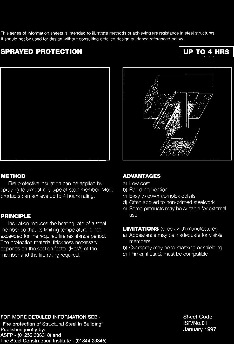
214 1282 Fire resistance
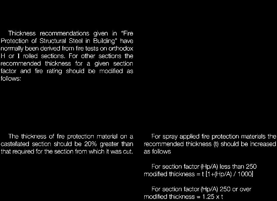
215 Fire resistance 1283
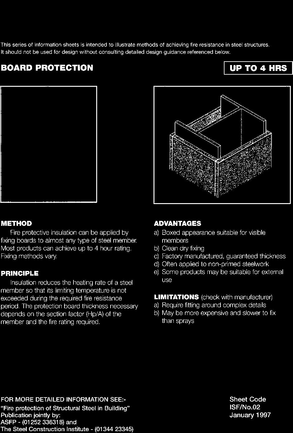
216 1284 Fire resistance

217 Fire resistance 1285
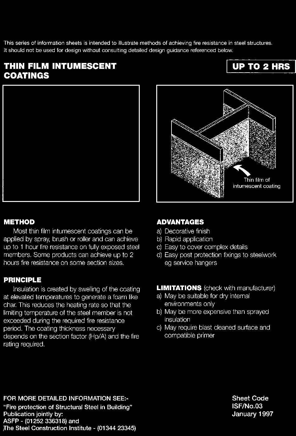
218 1286 Fire resistance
219 Fire resistance 1287
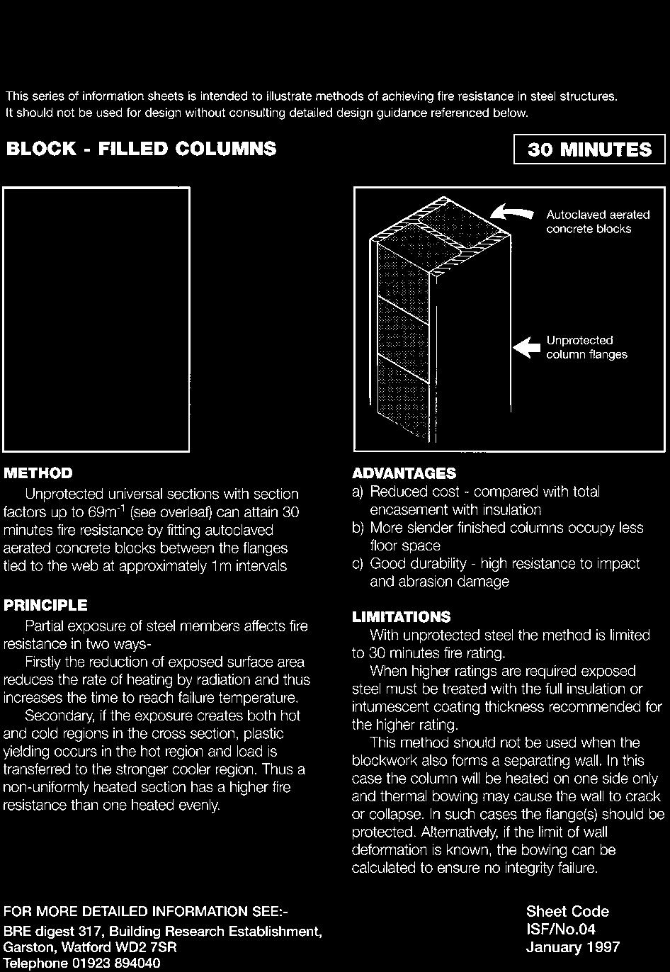
220 1288 Fire resistance
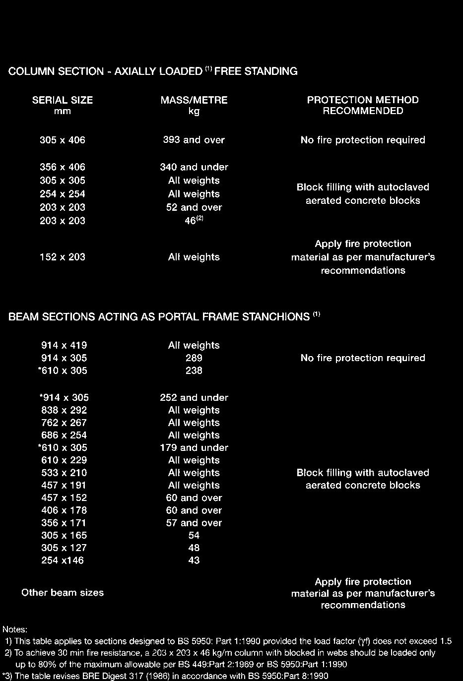
221 Fire resistance 1289
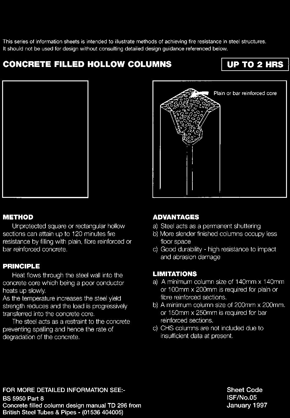
222 1290 Fire resistance
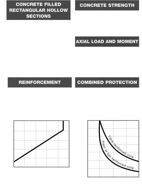
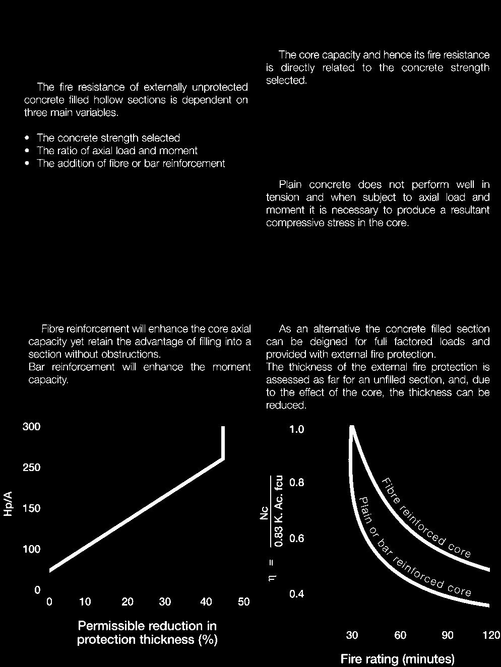
223 Fire resistance 1291
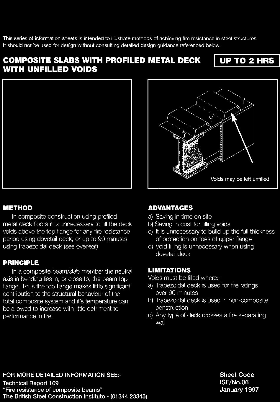
224 1292 Fire resistance
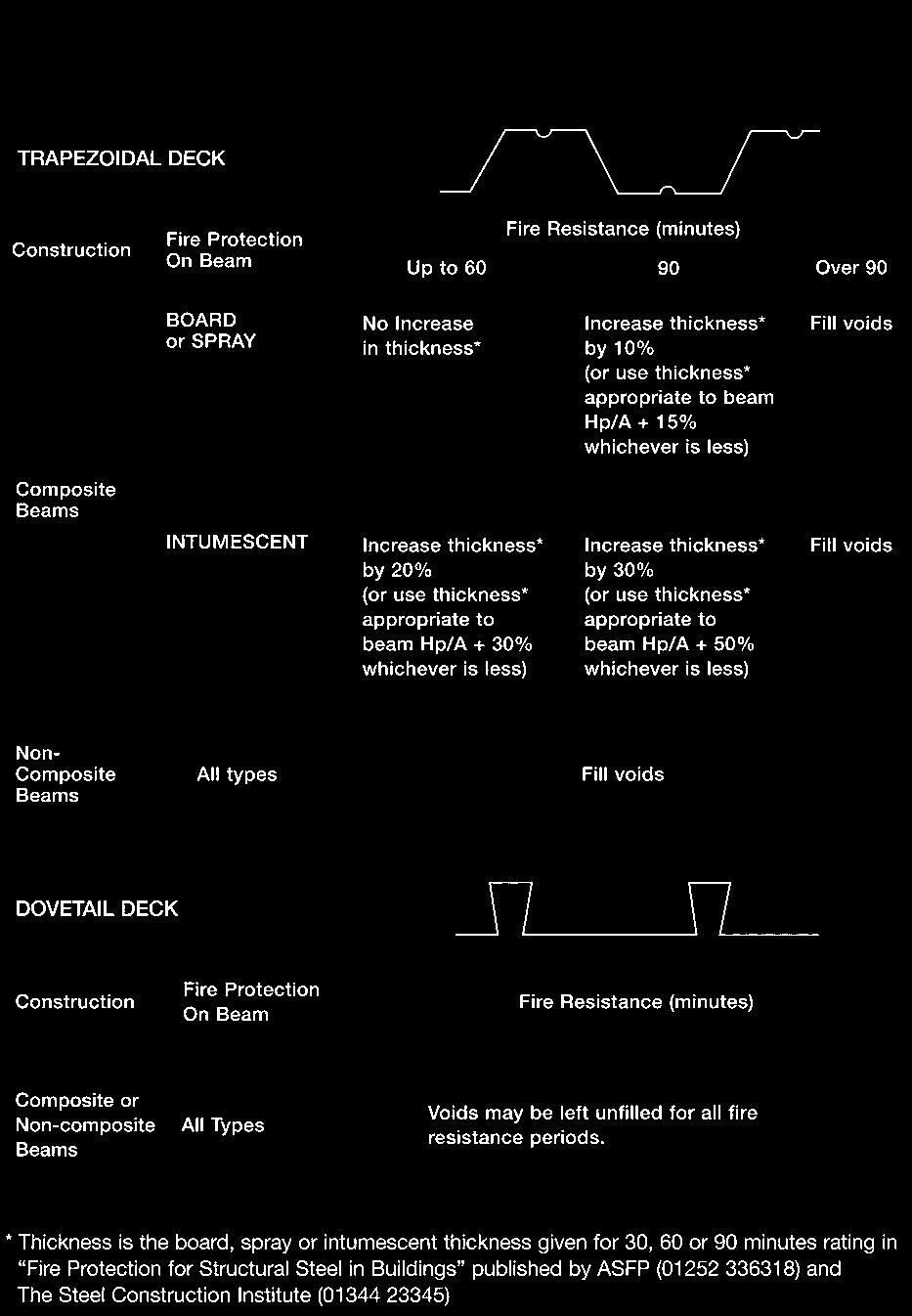
225 Fire resistance 1293
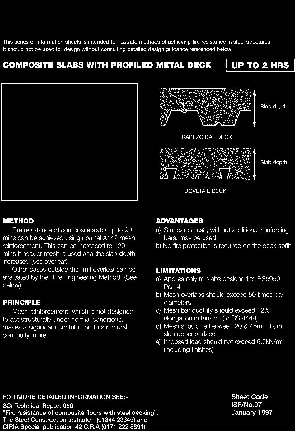
226 1294 Fire resistance
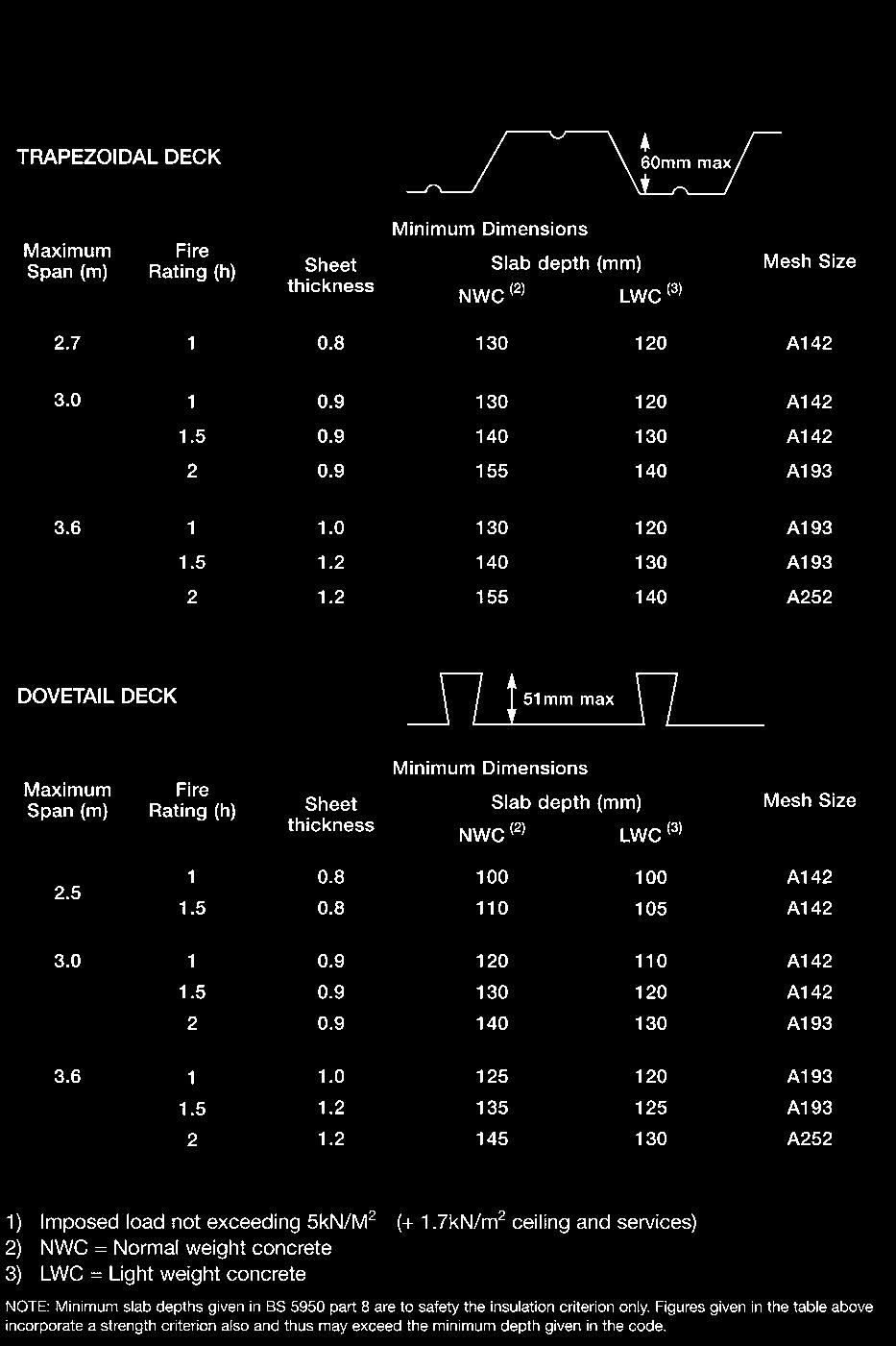
227 Fire resistance 1295
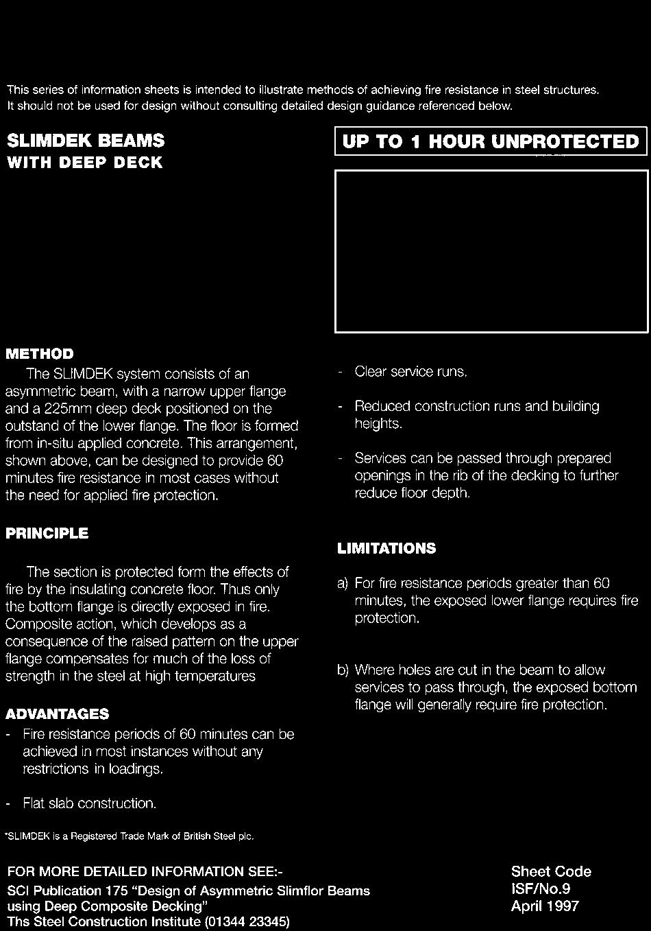
228 1296 Fire resistance
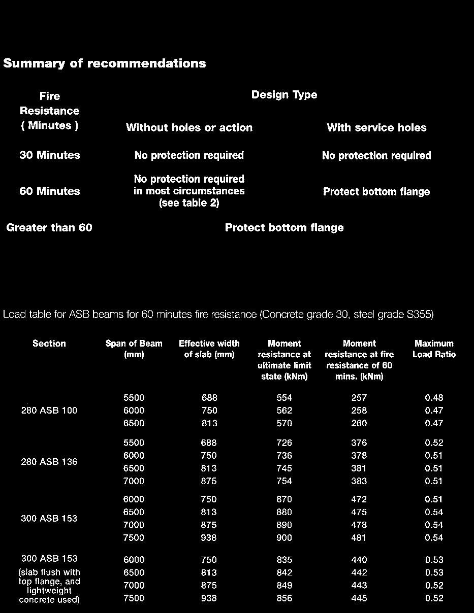
229 Fire resistance 1297
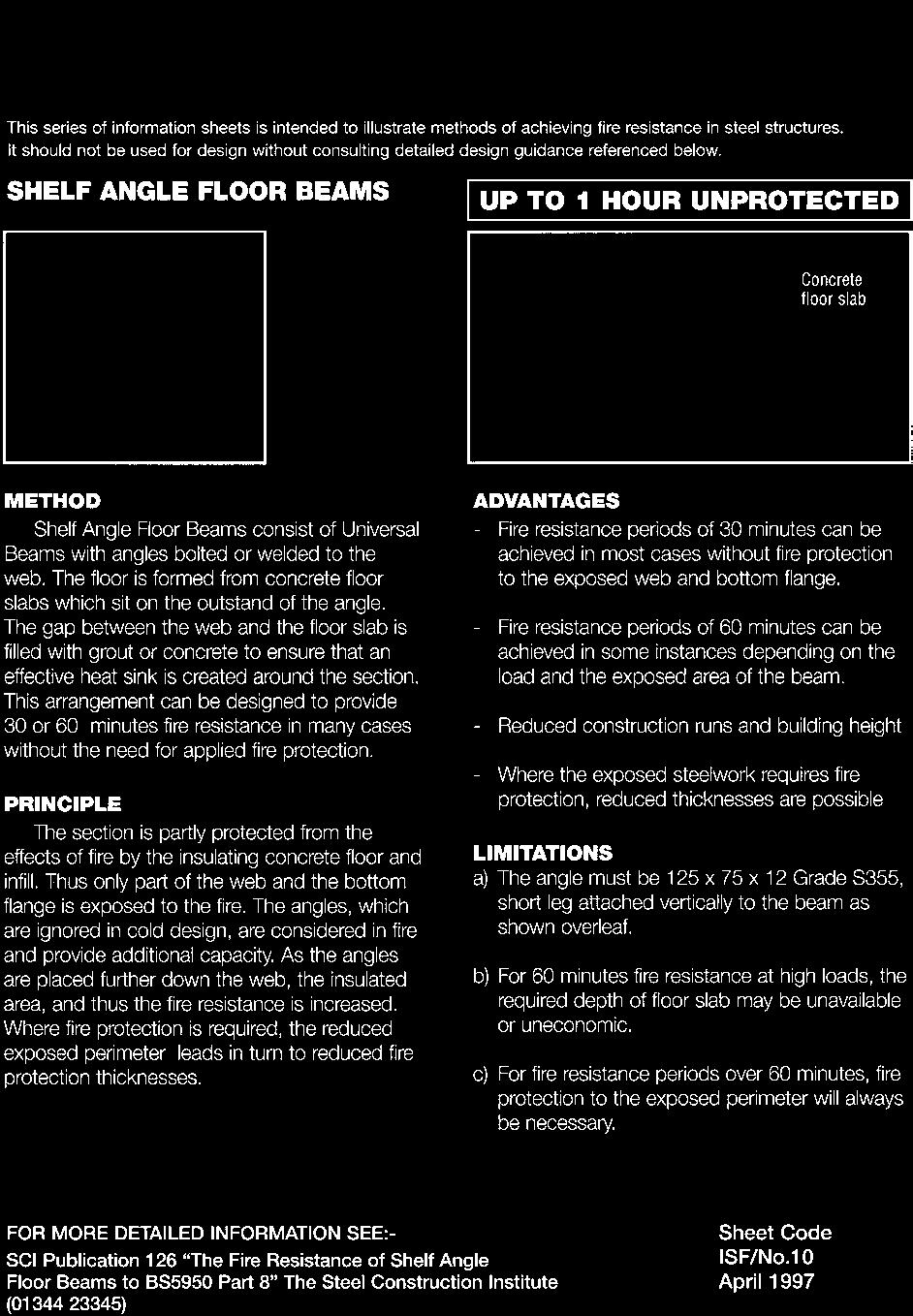
230 1298 Fire resistance
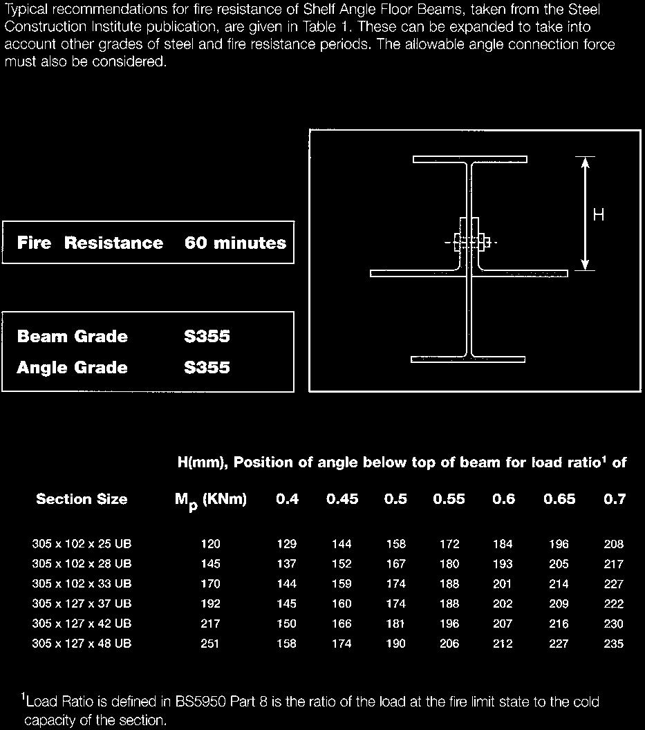
231 Fire resistance 1299
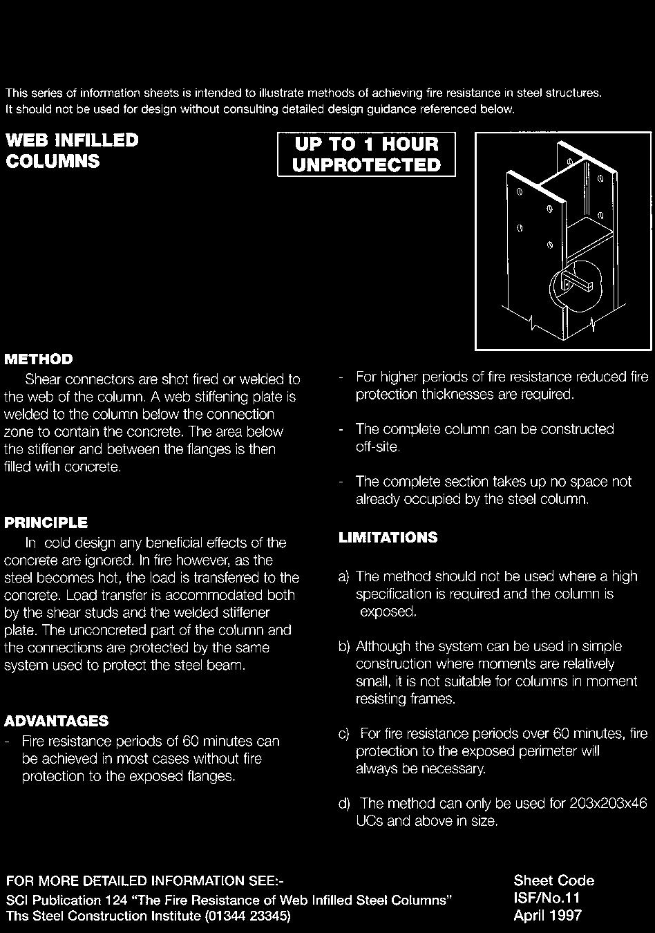
232 1300 Fire resistance
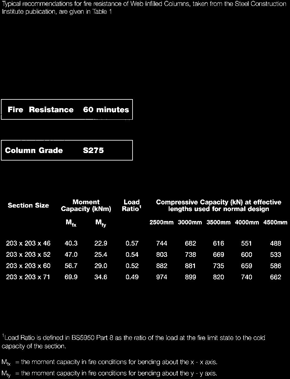
233 Fire resistance 1301
BS EN Cold formed welded structural hollow sections of non alloyb and fine grain steels Tolerances, dimensions and sectional properties
 BS EN 10219 2 Cold formed welded structural hollow s of non alloyb and fine grain steels Tolerances, dimensions and al properties 1 Scope This part of EN 10219 specifies tolerances for cold formed welded
BS EN :2006. Hot finished structural hollow sections of non alloy and fine grain steels
 . BS EN 1010 :006 Hot finished structural hollow sections of non alloy and fine grain steels 1 Scope This part of EN 1010 specifies tolerances for hot finished circular, square, rectangular and elliptical
Product Range Handbook
 Product Range Handbook 1 Where to find us Building 144 Culham Number 1 Site Station Road CULHAM Oxon OX14 3DA Sales: +44 (0)1865 409300 Fax: +44 (0)1865 407991 2 INDEX PAGE ROUND BARS 4 SQUARE BAR 5 TEES
1-3/8" inside-to-inside dimension. length of the leg. S162
 Member Designation MEMBER DEPTH: FLANGE WIDTH: STIFFENER LIP: Member Depths are taken in 1/100 inches. Flange Widths are taken in 1/100 inches. Member Flange Width Stiffener Lip (in) For Track Sections,
DESIGN OF MACHINE MEMBERS - I
 R10 Set No: 1 III B.Tech. I Semester Regular and Supplementary Examinations, December - 2013 DESIGN OF MACHINE MEMBERS - I (Mechanical Engineering) Time: 3 Hours Max Marks: 75 Answer any FIVE Questions
Supreme. Supreme Framing System. Product Catalog IAPMO UNIFORM ER #0313
 Supreme Supreme Framing System Product Catalog IAPMO UNIFORM ER #0313 2507 Table of Contents Certification of Materials 5 LEED Credits 5 Independent Product Certification 5 Code Approvals, Performance
DeltaStud - Lightweight Steel Framing
 DeltaStud - Lightweight Steel Framing B C H A t P Load Tables for Wind Bearing and Combined Wind & Axial Load Bearing Condition January 2014 Table of Contents Commentary Introduction...3 Product Identification...3
IBC 2009/2012 COMPLIANT. Supreme Framing System. Product Catalog
 IBC 2009/2012 COMPLIANT 2507 Supreme Framing System Product Catalog Supreme Framing System The Benefits of Supreme Framing System Speak for Themselves What is the Supreme Framing System? Supreme Framing
Cold formed welded structural hollow sections of non-alloy and fine grain steels
 BRITISH STANDARD BS EN 10219-2:2006 Cold formed welded structural hollow sections of non-alloy and fine grain steels Part 2: Tolerances, dimensions and sectional properties The European Standard EN 10219-2:2006
LIGHTWEIGHT STEEL FRAMING METRIC SECTION PROPERTIES
 C A N A D I A N S H E E T S T E E L B U I L D I N G I N S T I T U T E LIGHTWEIGHT STEEL FRAMING METRIC SECTION PROPERTIES wall stud floor joist track section & bridging channel properties 1 CSSBI 58A-2011
2507 (IBC 2006 ONLY) 3054 (IBC 2006 ONLY) Supreme Framing System Product Catalog
 3054 (IBC 2006 ONLY) Supreme Framing System Product Catalog") 12 0 2 / 2009IANT C B I PL COM 2507 (IBC 2006 ONLY) 3054 (IBC 2006 ONLY) R Supreme Framing System Product Catalog Supreme Framing System The Benefits of Supreme Framing System Speak for Themselves What
12 0 2 / 2009IANT C B I PL COM 2507 (IBC 2006 ONLY) 3054 (IBC 2006 ONLY) R Supreme Framing System Product Catalog Supreme Framing System The Benefits of Supreme Framing System Speak for Themselves What
DIN EN : (E)
") DIN EN 13480-3:2017-12 (E) Metallic industrial piping - Part 3: Design and calculation Contents Page European foreword... 10 1 Scope... 12 2 Normative references... 12 3 Terms, definitions, symbols and
DIN EN 13480-3:2017-12 (E) Metallic industrial piping - Part 3: Design and calculation Contents Page European foreword... 10 1 Scope... 12 2 Normative references... 12 3 Terms, definitions, symbols and
Long products and wire rod
 production prograe Long products and wire rod Mittal Steel Ostrava a.s. production prograe Long products and wire rod Mittal Steel Ostrava a.s. Mittal Steel Ostrava a.s. TRADITIONAL PRODUCER OF THE HIGH
Corus Tubes. Celsius. 355 Technical Guide. Structural Hollow Sections
 Corus Tubes Celsius 355 Technical Guide Structural Hollow Sections Contents 01 Introduction 02 Technical data 06 Production range charts 08 Sectional Properties Celsius 355 Circular 10 Sectional Properties
ArcelorMittal Europe - Long products Sections and Merchant Bars HISTAR. Innovative high strength steels for economical steel structures
 ArcelorMittal Europe - Long products Sections and Merchant Bars HISTAR Innovative high strength steels for economical steel structures Shanghai World Finance Center, P.R. China Innovative high strength
SEVENTH EDITION HOT ROLLED AND STRUCTURAL STEEL PRODUCTS
 SEVENTH EDITION HOT ROLLED AND STRUCTURAL STEEL PRODUCTS HOT ROLLED AND STRUCTURAL STEEL PRODUCTS CONTENTS INTRODUCTION 1 TEST CERTIFICATES AND 2 CERTIFICATES OF COMPLIANCE BUILD WITH STANDARDS AND ACRS
Purlins and Girts. A division of Canam Group
 Purlins and Girts A division of Canam Group TABLE OF CONTENTS OUR SOLUTIONS AND SERVICES............................................................ 5 Cautionary statement..................................................................
UNIT IV DESIGN OF ENERGY STORING ELEMENTS. Prepared by R. Sendil kumar
 UNIT IV DESIGN OF ENERGY STORING ELEMENTS Prepared by R. Sendil kumar SPRINGS: INTRODUCTION Spring is an elastic body whose function is to distort when loaded and to recover its original shape when the
DEPARTMENT OF MECHANICAL ENGINEERING
 DEPARTMENT OF MECHANICAL ENGINEERING UABMCC01-DESIGN OF MACHINE ELEMENTS QUESTION BANK Prepared By: Dr.S.Prabhakaran, Associate Professor/Mechanical Engg. Unit -1 STEADY STRESSES AND VARIABLE STRESSES
Revision and Errata List AISC Steel Construction Manual, 13 th Edition, Third Printing (Revision 2 June 2010)
") Revision and Errata List AISC Steel Construction Manual, 13 th Edition, Third Printing (Revision 2 June 2010) The following list represents corrections that have been made in the Fourth Printing of the
Revision and Errata List AISC Steel Construction Manual, 13 th Edition, Third Printing (Revision 2 June 2010) The following list represents corrections that have been made in the Fourth Printing of the
Structural Sections. Page 15
 Page 15 MILD STEEL CHANNELS Product Shortname: CH AS 3679-300 AS 3679-350 (on indent only) BS4360-43A Mass per Metre = area of section x 0.00785 = kg/m Metres per Tonne = 1000 = metres kg/m Size (A x B)
B.TECH III Year I Semester (R09) Regular & Supplementary Examinations November 2012 DYNAMICS OF MACHINERY
 Regular & Supplementary Examinations November 2012 DYNAMICS OF MACHINERY") 1 B.TECH III Year I Semester (R09) Regular & Supplementary Examinations November 2012 DYNAMICS OF MACHINERY (Mechanical Engineering) Time: 3 hours Max. Marks: 70 Answer any FIVE questions All questions
1 B.TECH III Year I Semester (R09) Regular & Supplementary Examinations November 2012 DYNAMICS OF MACHINERY (Mechanical Engineering) Time: 3 hours Max. Marks: 70 Answer any FIVE questions All questions
4.5 COMPOSITE STEEL AND CONCRETE
 4.5 COMPOSITE STEEL AND CONCRETE 4.5.1 RULES OF THUMB 4.5 Composite Steel and Concrete (1/11) Typical starting point Overall concrete depth 130mm (Grade 30) Depth of profiled decking 60mm Size beam with
Expanding Your Solutions. Steel Framing and Accessories. ICC ESR and 2015 IBC, IRC
 Expanding Your Solutions Steel Framing and Accessories ICC ESR-30 20 and 2015 IBC, IRC Effective 1/4/2017 Table of Contents Introduction to CEMCO... 1 Product Identification... 2 3 LEED Certification...
DYWIDAG Marine Tie Rods Smooth Bars & Walings
 DYWIDAG Marine Tie Rods Smooth Bars & Walings 2 Contents General Information... 4 Fields of Applications... 4 Overview of Steel Grades... 5 Steel Properties... 5 Thread Creation... 6 Key Advantages of
UNIT-3 PART-A C.K.GOPALAKRISHNAN, AP/MECH, MAHALAKSHMI ENGINEERING COLLEGE, TRICHY
 UNIT-3 PART-A 1. List the loads normally acting on a shaft? Bending load Torsional load or tw isting load. Axial thrust. 2. Write dow n the expression for the power transmitted by a shaft. P=2π NT/60 Where
Sections. Price Extras Pounds Sterling Effective on all deliveries from 01 April 2016 PRICE LIST
 Sections Price Extras Pounds Sterling Effective on all deliveries from 01 April 16 PRICE LIST SASPL:ENG:0416 This document shows price extras only. The invoiced price comprises these extras plus basis
Structural steel equal and unequal leg
 BRITISH STANDARD BS EN 10056-1:1999 The European Standard has the status of a British Standard ICS 77.140.70 NO COPYING WITHOUT BSI PERMISSION EXCEPT AS PERMITTED BY COPYRIGHT LAW Structural steel equal
Bulb flats For plate stiffening
 Corus Special Profiles Bulb flats For plate stiffening Introduction Plate stiffening 2 Bulb flats Introduction Bulb flats are tailor made for plate stiffening applications. Their special shape provides
Hybox 355 technical guide Structural hollow sections
 Hybox 355 technical guide Structural hollow sections Contents 03 Introduction 04 Technical data 06 Size range charts 08 Sectional properties Hybox 355 Circular 11 Sectional properties Hybox 355 Square
DEUTSCHE NORM October Structural steel equal and unequal leg angles Part 1: Dimensions English version of DIN EN
 DEUTSCHE NORM October 1998 Structural steel equal and unequal leg angles Part 1: Dimensions English version of DIN EN 10056-1 { EN 10056-1 ICS 77.140.70 Descriptors: Structural steel, angles, dimensions.
VALLIAMMAI ENGINEERING COLLEGE DEPARTMENT OF MECHANICAL ENGINEERING ME6503 DESIGN OF MACHINE ELEMENTS QUESTION BANK
 VALLIAMMAI ENGINEERING COLLEGE DEPARTMENT OF MECHANICAL ENGINEERING ME6503 DESIGN OF MACHINE ELEMENTS QUESTION BANK Unit -1 STEADY STRESSES AND VARIABLE STRESSES IN MACHINE MEMBERS Part-A 1. What are the
Technical Data Sheet. British Standards Compliant. TECHNICAL DATA SHEET System 160 (British Standards)
") Technical Data Sheet British Standards Compliant Mass 10 System 160 Mass 25 Mass 50 MAT 75 / 125 Superprop Hydraulics Quickbridge MU Falsework MU Bridging Compact Bridging BarrierGuard 800 Instrumentation
Technical Data Sheet British Standards Compliant Mass 10 System 160 Mass 25 Mass 50 MAT 75 / 125 Superprop Hydraulics Quickbridge MU Falsework MU Bridging Compact Bridging BarrierGuard 800 Instrumentation
CABLE MANAGEMENT SOLUTIONS CATALOGUE2003/04 A COMPLETE CABLE MANAGEMENT SOLUTION FOR COMMERCIAL AND INDUSTRIAL APPLICATIONS.
 CABLE MANAGEMENT SOLUTIONS CATALOGUE03/04 A COMPLETE CABLE MANAGEMENT SOLUTION FOR COMMERCIAL AND INDUSTRIAL APPLICATIONS www.legrand.co.uk CHANNEL SUPPORT THE BACKBONE OF ALL YOUR SUPPORT NEEDS Swifts
PIPINGSOLUTIONS, INC.
 Piping Stress Analysis Where do I start? The following information will take you step-by-step through the logic of the data collection effort that should occur prior to beginning to model a piping system
DESIGN OF MACHINE ELEMENTS UNIVERSITY QUESTION BANK WITH ANSWERS. Unit 1 STEADY STRESSES AND VARIABLE STRESSES IN MACHINE MEMBERS
 DESIGN OF MACHINE ELEMENTS UNIVERSITY QUESTION BANK WITH ANSWERS Unit 1 STEADY STRESSES AND VARIABLE STRESSES IN MACHINE MEMBERS 1.Define factor of safety. Factor of safety (FOS) is defined as the ratio
 DEPARTMENT OF MECHANICAL ENGINEERING Subject code: ME6601 Subject Name: DESIGN OF TRANSMISSION SYSTEMS UNIT-I DESIGN OF TRANSMISSION SYSTEMS FOR FLEXIBLE ELEMENTS 1. What is the effect of centre distance
NME-501 : MACHINE DESIGN-I
 Syllabus NME-501 : MACHINE DESIGN-I UNIT I Introduction Definition, Design requirements of machine elements, Design procedure, Standards in design, Selection of preferred sizes, Indian Standards designation
Design principles and Assumptions
 Design principles and Assumptions The design and use of concrete slabs that utilise ARMOURDECK 300 in composite construction may be carried out using either: the relevant Australian and international Standards
Celsius 355 NH technical guide Structural hollow sections
 Celsius 355 NH technical guide Structural hollow sections Contents 03 Introduction 04 echnical data 08 Size range charts 12 Sectional properties Celsius 355 Circular 16 Sectional properties Celsius 355
STRUCTURAL STAINLESS STEEL DESIGN TABLES IN ACCORDANCE WITH AISC DG27: STRUCTURAL STAINLESS STEEL
 STRUCTURAL STAINLESS STEEL DESIGN TABLES IN ACCORDANCE WITH AISC DG27: STRUCTURAL STAINLESS STEEL Explanatory Notes: Version 1.0 11/6/2017 SCI (The Steel Construction Institute) is the leading, independent
Profile series I-40. System kit Profile series I-40
 Profile series I-40 System kit Profile series I-40 n n n a n n n R n a R 45 Profile series I-40 Contents 1 Technical data/profile machining F f Page 1 2 Page 1 3 Page 1 5 Page 1 8 Profiles Page 2 2 3000
ROOFING SOLUTIONS DESIGN GUIDE PURLINS AND GIRTS DESIGN GUIDE PURLINS AND GIRTS S&T029N
 DESIGN GUIDE PURLINS AND GIRTS ROOFING SOLUTIONS DESIGN GUIDE PURLINS AND GIRTS S&T029N JUL 2015 CONTENTS INTRODUCTION 2 Acknowledgements 2 Disclaimer 2 Product Technical Statement 3 Producer Statement
3.1 Available sections, terms of delivery
 3.1 Interlocks LARSSEN section Interlock design conforming to DIN EN 10248-2 and E 67 of EAU 2004 LARSSEN 43, 430 HOESCH section (LARSSEN interlock) Interlock design conforming to DIN EN 10248-2 and E
M-18 Controllable-Pitch Propeller
 Guideline No.M-18(201510) M-18 Controllable-Pitch Propeller Issued date: 20 th October, 2015 China Classification Society Foreword This Guideline is a part of CCS Rules, which contains technical requirements,
Properties of Structural-Steel Shapes
 E Proties of Strutural-Steel Shapes In the following tables, the proties of a few strutural-steel shapes are presented as an aid to the reader in solving problems in the text. These tables were ompiled
contents MALLEABLE PIPE FITTINGS BUsHEs NiPPlEs PlUgs caps BENds BackNUTs UNioNs TEEs 171 cross PN25 p socket PN25 p socket PN25 p.
 contents BUsHEs 140 Hexagon Bush p.5 NiPPlEs 144 octagon Nipple p.6 145 Hexagon Nipple p.6 PlUgs 146 Beaded Plug - solid p.7 147 Plain Plug - Hollow p.7 148 Plain Plug - solid p.7 149 countersunk Plug
Eurocode 3 Design of steel structures
 BRITISH STANDARD BS EN 1993-1-5:2006 Incorporating corrigendum April 2009 Eurocode 3 Design of steel structures Part 1-5: Plated structural elements ICS 91.010.30; 91.080.10 National foreword This British
STANDARD SPECIFICATIONS
 American National Standard SJI-K 1.1 STANDARD SPECIFICATIONS FOR OPEN WEB STEEL JOISTS, K-SERIES SECTION 1. SCOPE Adopted by the Steel Joist Institute November 4, 1985 Revised to November 10, 2003 - Effective
Overview. HDS replaces built-up curtain wall headers. HDS replaces load-bearing box beam headers
 Overview The Heavy-Duty Stud (HDS ) Framing System is a high-performance, costeffective, multipurpose, heavy-duty framing stud for headers, jambs, posts and built-up tube truss chords and webs. The superior
STANDARD SPECIFICATION
 STANDARD SPECIFICATION FOR OPEN WEB STEEL JOISTS, K-SERIES Adopted by the Steel Joist Institute November 4, 1985 Revised to May 18, 2010, Effective December 31, 2010 SECTION 1. SCOPE AND DEFINITION 1.1
DESIGN OF MACHINE MEMBERS I ASSIGNMENT
 SHRI VISHNU ENGINEERING COLLEGE FOR WOMEN DESIGN OF MACHINE MEMBERS I ASSIGNMENT UNIT I 1 a). Draw stress strain diagram for the ductile and brittle material and compare them? show the salient points on
CONTENT. 1. Syllabus 2. Introduction 3. Shaft 4. Coupling. Rigid coupling. Flange coupling. Sleeve (or) muff coupling Split muff coupling
 muff coupling Split muff coupling") UNIT II 1. Syllabus 2. Introduction 3. Shaft 4. Coupling Rigid coupling CONTENT Flange coupling Protected flange coupling Unprotected flange coupling Marine type flange coupling Sleeve (or) muff coupling
UNIT II 1. Syllabus 2. Introduction 3. Shaft 4. Coupling Rigid coupling CONTENT Flange coupling Protected flange coupling Unprotected flange coupling Marine type flange coupling Sleeve (or) muff coupling
Plate Girder and Stiffener
 Plate Girder and Stiffener (Gelagar Pelat dan Pengaku) Dr. AZ Department of Civil Engineering Brawijaya University Introduction These girders are usually fabricated from welded plates and thus are called
GENERAL INFORMATION FEATURES.
 TECHNICAL GUIDE GENERAL INFORMATION SUPERIOR ENGINEERED JOIST SYSTEMS JoistRite is a specially designed, patented, cold-formed steel section that has one of the highest strength-to-mass ratios of any structural
2. Write the expression for estimation of the natural frequency of free torsional vibration of a shaft. (N/D 15)
") ME 6505 DYNAMICS OF MACHINES Fifth Semester Mechanical Engineering (Regulations 2013) Unit III PART A 1. Write the mathematical expression for a free vibration system with viscous damping. (N/D 15) Viscous
ME 6505 DYNAMICS OF MACHINES Fifth Semester Mechanical Engineering (Regulations 2013) Unit III PART A 1. Write the mathematical expression for a free vibration system with viscous damping. (N/D 15) Viscous
Technical Data MM Channel
 Technical Data MM Channel The enclosed pages are taken from the Installation Systems Catalogue 2015 for additional information please visit the technical library at www.hilti.co.uk or call our Technical
DARSHAN INSTITUTE OF ENGG. & TECH.
 DARSHAN INSTITUTE OF ENGG. & TECH. B.E. Semester V Design of Machine Elements (2151907) Batch: Roll No.: List of Assignments Sr. No. Title Start Date End Date Sign Remark 1. Introduction 2. Design against
FLUSH SEAT DESIGN GUIDE FOR USE WITH ECOSPAN COMPOSITE JOISTS. economy THROUGH ecology. v1.3
 FLUSH SEAT DESIGN GUIDE FOR USE WITH ECOSPAN COMPOSITE JOISTS economy THROUGH ecology v1.3 Nucor-Vulcraft / Verco Group Ecospan Composite Floor System 6230 Shiloh Road Suite 140 Alpharetta, GA 30005 P:
INDEX ABOUT OUR GROUP... 5 UNIVERSAL BEAMS... 6 UNIVERSAL COLUMNS... 9 EUROPEAN SPECIFICATION BEAMS WITH PARALLEL FLANGES... 10
 PRODUCT CATALOGUE 1 2 3 INDEX ABOUT OUR GROUP... 5 UNIVERSAL BEAMS... 6 UNIVERSAL COLUMNS... 9 EUROPEAN SPECIFICATION BEAMS WITH PARALLEL FLANGES... 10 MS CHEQUERED SHEETS... 13 CHANNELS... 14 HOT ROLLED
PRODUCT CATALOGUE LOUCON METAL LTD. 37 and 39 Grenfell Crescent, Nepean, ON K2G 0G3. Hours of Operation: Monday-Friday 8:00 AM 5:00 PM
 PRODUCT CATALOGUE 37 and 39 Grenfell Crescent, Nepean, ON K2G 0G3 Hours of Operation: Monday-Friday 8:00 AM 5:00 PM Phone: (613) 226-1102 Fax: (613) 226-6097 e-mail: info@louconmetal.com web: www.louconmetal.com
CERTIFICATES OF COMPETENCY IN THE MERCHANT NAVY MARINE ENGINEER OFFICER
 CERTIFICATES OF COMPETENCY IN THE MERCHANT NAVY MARINE ENGINEER OFFICER EXAMINATIONS ADMINISTERED BY THE SCOTTISH QUALIFICATIONS AUTHORITY ON BEHALF OF THE MARITIME AND COASTGUARD AGENCY STCW 95 CHIEF
Hours / 100 Marks Seat No.
 17610 16172 4 Hours / 100 Seat No. Instructions (1) All Questions are Compulsory. (2) Answer each next main Question on a new page. (3) Illustrate your answers with neat sketches wherever necessary. (4)
DNVGL-CG-0194 Edition July 2017
 CLASS GUIDELINE DNVGL-CG-0194 Edition July 2017 The content of this service document is the subject of intellectual property rights reserved by ("DNV GL"). The user accepts that it is prohibited by anyone
WARRANTY AND LIMITATIONS
 2 GENERAL INFORMATION QUALITY AND SERVICE COUNT Marino\Ware is proud to present this catalog that details our Lightweight Steel Framing Products. For over 70 years, Marino\Ware has been providing their
ROUGH OPENINGS PRODUCT CATALOG STRONGER THAN STEEL. INTERIOR AND EXTERIOR FRAMING
 PRODUCT CATALOG STRONGER SM THAN STEEL. INTERIOR AND EXTERIOR FRAMING MADE EASY. Rough openings have always been a challenge on the jobsite. At ClarkDietrich, we make them easy. Our collection of rough
Multideck 60-V2. Contents
 The original and still the most popular deck in the market is a 60mm high, structurally efficient trapezoidal profile providing an excellent composite union between steel and concrete to maximise the load
III B.Tech I Semester Supplementary Examinations, May/June
 Set No. 1 III B.Tech I Semester Supplementary Examinations, May/June - 2015 1 a) Derive the expression for Gyroscopic Couple? b) A disc with radius of gyration of 60mm and a mass of 4kg is mounted centrally
Side Structures in Single Side Skin Bulk Carriers
 (1992) (Rev.1 1997) (Rev.2.1 1997) (Rev.3 Sept 2000) (Rev.4 July 2004) (Rev.5 May 2010) Side Structures in Single Side Skin Bulk Carriers.1 Application and definitions These requirements apply to side
B.Tech. MECHANICAL ENGINEERING (BTMEVI) Term-End Examination December, 2012 BIMEE-007 : ADVANCED DYNAMICS OF MACHINE
 Term-End Examination December, 2012 BIMEE-007 : ADVANCED DYNAMICS OF MACHINE") No. of Printed Pages : 5 BIMEE-007 B.Tech. MECHANICAL ENGINEERING (BTMEVI) Term-End Examination 01601 December, 2012 BIMEE-007 : ADVANCED DYNAMICS OF MACHINE Time : 3 hours Maximum Marks : 70 Note : Attempt
No. of Printed Pages : 5 BIMEE-007 B.Tech. MECHANICAL ENGINEERING (BTMEVI) Term-End Examination 01601 December, 2012 BIMEE-007 : ADVANCED DYNAMICS OF MACHINE Time : 3 hours Maximum Marks : 70 Note : Attempt
BIMEE-007 B.Tech. MECHANICAL ENGINEERING (BTMEVI) Term-End Examination December, 2013
 Term-End Examination December, 2013") No. of Printed Pages : 5 BIMEE-007 B.Tech. MECHANICAL ENGINEERING (BTMEVI) Term-End Examination December, 2013 0 0 9 0 9 BIMEE-007 : ADVANCED DYNAMICS OF MACHINE Time : 3 hours Maximum Marks : 70 Note
No. of Printed Pages : 5 BIMEE-007 B.Tech. MECHANICAL ENGINEERING (BTMEVI) Term-End Examination December, 2013 0 0 9 0 9 BIMEE-007 : ADVANCED DYNAMICS OF MACHINE Time : 3 hours Maximum Marks : 70 Note
Geomembrane Test Methods
 Appendix 2 Geomembrane Test Methods AMERICAN SOCIETY FOR TESTING AND MATERIALS (arranged by number) ASTM D-5 ASTM D-36 ASTM D-256 ASTM D-412 ASTM D-413 ASTM D-471 ASTM D-570 ASTM D-638 ASTM D-696 ASTM
Bolt resistances: Class 10.9 Csk TCB: Non-preloaded using S275
 Non-preloaded using S275 Single shear Double shear d A s F t,rd F v,rd 2 x F v,rd mm mm 2 kn kn kn 12 84.3 42.5 28.7 57.3 16 157 79 62.8 125.6 20 245 123 98 196 22 303 153 121 242 24 353 178 141 282 27
Overhead transmission lines Spacers
 = SVENSKA KRAFTNÄT SWEDISH NATIONAL GRID UNIT, BUSINESS AREA AEL, Asset Management Lines OUR REFERENCE TR05-08E DATE 2016-06-09 CONSU12TATIONS TECHNICAL GUIDELINE REVISION 3 APPROVED Overhead transmission
Multideck 80-V2 Features and Applications
 Features and Applications is designed to incorporate all the advantages of the Multideck 60-V2 but in a deeper profile to provide longer spans up to 5.4m unpropped. Concrete Volume Savings Due to its unique
P I P E F I T T I N G S OUR GENIUS IS PIPE FITTINGS
 MALLEABLE P I P E F I T T I N G S OUR GENIUS IS PIPE FITTINGS Specification Pipe Threads The machined threads of Crane fittings are supplied to conform with the gauging requirements of BS EN 10226-2 and
Cable ladder systems. Development and testing
 Cable ladder systems Metsec cable ladder systems have been developed to provide cost effective solutions for the support of cables in a wide range of market sectors. These sectors include: * Coercial *
R10 Set No: 1 ''' ' '' '' '' Code No: R31033
 R10 Set No: 1 III B.Tech. I Semester Regular and Supplementary Examinations, December - 2013 DYNAMICS OF MACHINERY (Common to Mechanical Engineering and Automobile Engineering) Time: 3 Hours Max Marks:
Piling Product Guide Edition. Servicesteel.org
 Piling Product Guide 2017 Edition Strong Foundations Starith Service Steel Service Steel Supplies All Your Foundation Products You Are Our Number One Priority From industry leading steel sheet piling to
English translation authorized by DIBt Original version in German language
 Date: Reference: 29/09/2014 I 36-1.14.4-101/13 English translation authorized by DIBt Original version in German language Approval number: Validity Z-14.4-2 from: 29 September 2014 Applicant: Lindapter
CERTIFIED TO ISO 9001:2008 CERT NO:AR 0994
 CERTIFIED TO ISO 9001:2008 CERT NO:AR 0994 www.melewar-mig.com MELEWAR STEEL TUBE SDN. BHD. (111059-D) Lot 53 Persiaran Selangor, 40200 Shah Alam, Selangor Darul Ehsan. Malaysia Tel : 603-5519 2455 (12
Torque steer effects resulting from tyre aligning torque Effect of kinematics and elastokinematics
 P refa c e Tyres of suspension and drive 1.1 General characteristics of wheel suspensions 1.2 Independent wheel suspensions- general 1.2.1 Requirements 1.2.2 Double wishbone suspensions 1.2.3 McPherson
KINGS COLLEGE OF ENGINEERING DEPARTMENT OF MECHANICAL ENGINEERING
 KINGS COLLEGE OF ENGINEERING DEPARTMENT OF MECHANICAL ENGINEERING QUESTION BANK Sub Code/Name: ME 1352 DESIGN OF TRANSMISSION SYSTEMS Year/Sem: III / VI UNIT-I (Design of transmission systems for flexible
Design and Vibrational Analysis of Flexible Coupling (Pin-type)
") Design and Vibrational Analysis of Flexible Coupling (Pin-type) 1 S.BASKARAN, ARUN.S 1 Assistant professor Department of Mechanical Engineering, KSR Institute for Engineering and Technology, Tiruchengode,
Design and Vibrational Analysis of Flexible Coupling (Pin-type) 1 S.BASKARAN, ARUN.S 1 Assistant professor Department of Mechanical Engineering, KSR Institute for Engineering and Technology, Tiruchengode,
Bearing retention and clearances
 Bearing retention and clearances Bearing retention 9 Radial retention 9 Axial retention 91 Positioning of single bearing assemblies 91 Positioning of two bearing assemblies 92 Axial retention processes
Taiwan Bicycle Industry Standard
 TBIS 4210 5:2016 Taiwan Bicycle Industry Standard TBIS 4210-5 First edition 2016.01.01 Cycles Safety requirements for bicycles Part 5: Steering test methods Reference number: TBIS 4210-5:2015 (FDTS) TBIS
ISO 2953 INTERNATIONAL STANDARD. Mechanical vibration Balancing machines Description and evaluation
 INTERNATIONAL STANDARD ISO 2953 Third edition 1999-04-15 Mechanical vibration Balancing machines Description and evaluation Vibrations mécaniques Machines à équilibrer Description et évaluation A Reference
Contents
 Contents 1 2-3 4 5 6-7 8 9 10 11 12 13 14 15-19 20-26 27 28 29 30 31 32 33 A Word about Steel Pipe Company Profile & Premises and Plants of Melewar Steel Tube Sdn. Bhd. Main Products Quality Products Quality
Shaft-Hub-Connections
 Stand: 14.01.2010 Shaft-Hub-Connections Shrink Discs Cone Clamping Elements Star Discs 36 Edition 2012/2013 RINGSPANN Eingetragenes Warenzeichen der RINGSPANN GmbH, Bad Homburg Table of Contents Introduction
Bulb Flats. Light weight corrosion resistant solution for plate stiffening
 Bulb Flats Light weight corrosion resistant solution for plate stiffening 2 CRANE BULB FLATS RAIL Photo courtesy of: Andrew Linnett/MOD Introducing British Steel British Steel is a world leader in the
Shaft Design. Dr. Mostafa Rostom A. Atia Associate Prof.
 Shaft Design Dr. Mostafa Rostom A. Atia Associate Prof. 1 Loading modes A shaft is a rotating member, usually of circular cross section, used to transmit power or motion. It provides the axis of rotation,
ÅLASTRON S.A. Ag. Ioannis str., Ag. Ioannis Aspropyrgos Tel.: Fax:
 ÅLASTRON S.A. Ag. Ioannis str., Ag. Ioannis 193 00 Aspropyrgos Tel.: +30 210 5515000 Fax: +30 210 5515015 www.elastron.gr elastron@elastron.gr 1 RECTANGULAR HOLLOW SECTIONS (EN 10219) Dimensions Cross
COMPFIRE. Reaction Frame. Camera 3. Macalloy Bars. Camera 2. Link Bar. Support Beam. Oven Bar. Camera 1. Jack Bar.
 Reaction Frame Macalloy Bars Camera 3 Support Beam α Oven Bar Camera 2 Link Bar Camera 1 Tested Connection Jack Bar Electrical Furnace Reaction Frame Load Jack 22 September 2010 1 Oven Bar Link Bar View
Eurocode 3 Design of steel structures
 BRITISH STANDARD BS EN 1993-2:2006 Incorporating corrigendum July 2009 Eurocode 3 Design of steel structures Part 2: Steel bridges ICS 91.010.30; 91.080.10; 93.040 National foreword This British Standard
1 Variable spring supports Design Instructions
 Design Instructions 1.1 Application Rigid supporting structures are not capable to accommodate vertical displacement or large horizontal forced travels of piping. This nodes should be supported by spring
CONVEYOR MANUFACTURERS ASSOCIATION OF SA LIMITED STATIC SHAFT CONVEYOR PULLEYS WITH INTERNAL BEARINGS FOR CONVEYORS
 CONVEYOR MANUFACTURERS ASSOCIATION OF SA LIMITED STATIC SHAFT CONVEYOR PULLEYS WITH INTERNAL BEARINGS FOR CONVEYORS CMA MP01 Rev00 2013 Table of Contents 1 INTRODUCTION... 3 2 NORMATIVE REFERENCES... 3
ME 6503 DESIGN OF MACHINE ELEMENTS Mechanical Engineering Fifth Semester UNIT - 4 Part A
 ME 6503 DESIGN OF MACHINE ELEMENTS Mechanical Engineering Fifth Semester UNIT - 4 Part A 1. State any two functions of springs. (N/D 16) i) To provide cushioning effect or reduce the effect of shock or
Multideck 50-V2 Features and Applications
 Features and Applications is a dovetail profile deck with a depth of 50mm providing spans up to 4m unpropped. Greater Design Efficiency The larger range of Multideck gauge thicknesses available allow much
This document is a preview generated by EVS
 TECHNICAL SPECIFICATION ISO/TS 13725 Second edition 2016-06-01 Hydraulic fluid power Method for evaluating the buckling load of a hydraulic cylinder Transmissions hydrauliques Méthode d évaluation du flambage
Sheet 1 Variable loading
 Sheet 1 Variable loading 1. Estimate S e for the following materials: a. AISI 1020 CD steel. b. AISI 1080 HR steel. c. 2024 T3 aluminum. d. AISI 4340 steel heat-treated to a tensile strength of 1700 MPa.