C O N V E Y O R B E L T S
|
|
|
- Charlotte Blake
- 5 years ago
- Views:
Transcription

1 CONVEYOR BELTS
2
3 GENERAL INDEX INFO Why Eurobelt Product Range Materials INFO SERIES Types and characteristics Accessories SERIES A Types and characteristics Accessories SERIES Types and characteristics Accessories SERIES Types and characteristics Accessories SERIES Types and characteristics Accessories SERIES Types and characteristics Accessories SERIES Types and characteristics Accessories SERIES Types and characteristics Accessories TECHNICAL DATA Catenaries Wearstrips arrangement Chemical resistance Takeups Instructions Transferences Maintenance DATA A24 20 INDUSTRIES Car Meat Fish Poultry Vegetables Wine Beverage Confectionery 2 INDUSTRY

4 INFO EUROBELT AFHER EUROBELT S.A. is a leading company in the manufacture of plastic modular belts to transport food and industrial product. With more than 25 years of experience in the internal transport, finding and solving thousands of problems, EUROBELT offers a product range that responds with a high efficiency, even in the most unfavourable work conditions. To develop its activity, AFHER EUROBELT S.A. has a highly skilled staff, implicated in a continuous development and research, to offer to its customers a personalized advice as well as an efficient after-sales service. AFHER EUROBELT S.A. WHY EUROBELT Due to our position of leader in the conveyor belts market, it is really important for us to offer a continue innovation of our products. That is why, in Eurobelt, we have at our disposal modern equipments in order to give the best service to our customers. SALES DEPARTMENT We know your industry, your applications and your needs. For this reason, our sales department will provide you with all the technical advice your company might need from the first moment. Topacio, Valladolid SPAIN Tel.: Fax.: afher@eurobelt.com TECHNICAL DEPARTMENT A team of engineers, devoted exclusively to the development of new products, assures our commitment to supply the best solutions to all your demands. 3


5 INFO MANUFACTURE DISPATCH INFO The belts manufactured by Eurobelt are moulded with technical plastics which constitute a structure of pieces of injection that makes it be the suitable support for the transport of food and industrial products. The quality of our products is obtained by using upto-date equipments and plastic materials in all the manufacture process. In order to be able to offer the best delivery time in the market, Eurobelt has an area of 4,000 square metres to store the parts that will make up your conveyor belt. ASSEMBLY The pieces of injection are interlaced forming lines that joined by means of connecting rods, which are fastened at their ends by extractable caps, constitute your conveyor belt. This modular configuration allows to personalize you belt according to the needs of your application. QUALITY Eurobelt accomplishes quality controls and tests in all their production processes in order to offer the best product of the market. Once your belt has been finished, our shipping department carries out the last check before packing. Eurobelt uses the most modern packing methods so that your product do not suffer any damage during the transport. COMMITMENT Eurobelt guarantees a delivery time of 5 working days for your belt and, in case of urgency, less than 8 hours without any extra charge. AFTER-SALES SERVICE Our commitment, however, does not finish here. We will keep on working together so that your belt fulfil your expectations. DATA A INDUSTRY
6 INFO PRODUCT RANGE CONVEYOR BELTS Eurobelt belts are made of modules which are joined by means of connecting rods and that constitute the transport area. Their modular configuration allows to manufacture made-to-measure belts. Minimum coefficient of friction that avoids the traditional lubricant sprinkling, improving the work conditions, reducing the maintenance, and eliminating the problem of wet products. Excellent behaviour against the chemical aggression. Safety for workers when manipulating the product directly on the belt, avoiding the risk of accidents and improving therefore the work conditions. The retention system by extractable caps makes very easy the assembly and dismantling of the belt, as well as the re-use of the joining rods. ACCESSORIES EUROBELT has a wide range of accessories for the conveyor belts to give solution to the requirements and difficulties arising sometimes in the transport systems of packed and in-bulk products. The modular configuration of the belt enables to replace just the damaged accessory in a very short time, which implies a cost saving with regard to stops in production lines. CHARACTERISTICS Wide range of Accessories, Series and Types that combined respond to most of the requirements of internal transport. Due to their low weight, the support structures are light and easy to handle, needing motors of lesser power, which implies an energy saving. The materials employed in the production of the accessories have suitable characteristics depending on the work conditions: impact and wear resistance, chemical resistance, direct contact with food... All the accessories are in stock and their delivery time is immediate. 5


7 INFO SPROCKETS Both the shape of the modules and that of the sprockets are very important in the design of the different series. The perfect coupling of the modules to the sprockets assures a direct drive free of slips and lateral displacements, typical of the conventional traction systems. Only the central sprocket must be fastened, as it will guide the belt avoiding lateral displacements. To make this fastening we will use the retaining rings which do not need any groove to be made in the shaft. FLIGHTS The flights are special modules to be inserted across the belt, providing an area of retention for the product. They are used in applications to elevate, descend or accompany the product, avoiding that it slips along the belt. SIDE GUARDS The side guards are plastic accessories to be inserted into the belt structure to retain the product laterally, avoiding overflows and frictions with the conveyor structure itself. FINGER PLATES The finger plates have been designed to be used with the Raised Rib surface in applications of intersection of lines in which it is necessary to make the transfer of the product through the finger plates system. HOLD-DOWN ROLLERS The hold-down rollers are used to fasten the belt vertically to the conveyor in all the inflexions. Placed in the middle of the belt, in applications in which the belt must be submerged, they avoid that the belt bents due to the flotation. HOLD-DOWN PROFILES In order to make the fastening of the belt and to make its sliding easier, EUROBELT has designed two types of hold-down profiles, with different geometries, but with the same uses and services. WEARSTRIPS The flat wearstrips are fastened by means of flatheaded plastic screws, which provides a smooth surface free of any hooking. 6 DATA A24 20 INFO INDUSTRY


8 INFO MATERIALS POLYACETAL POLYPROPYLENE With a specific weight of 1.5 approximately, the technical polyacetals are the thermoplastics with the lowest coefficient of friction. That is why it is the material used in accumulation tables for all kind of containers, as damages and crushing on their surfaces are avoided. Its great mechanical resistance enables the polyacetal to transport heavy loads. It can support temperatures ranging from 40 ºC to +90 ºC, and it has a great resistance to penetration, so that it is used in manipulation processes in which it exists the possibility of cuts and impacts to take place. Good chemical resistance: to solvents, greases, and an extensive list of chemical agents. It fulfils the regulations of the F.D.A. to be used in food processing applications. The electrically conductive polyacetal stands out for its low electric resistance. It is the suitable material to dispel the electrostatic charges originated in the transport of containers or cans, due to the friction among themselves or with the belt. The use of this material together with metallic or electric-conductivematerial wearstrips makes easy the discharge to earth of the belt through the conveyor. With a specific weight of approximately 0.9, it floats in the water, and it is the material employed in most of the applications as it can bear temperatures ranging from +1 ºC to +104 ºC, as well as it is extremely resistant to traction. It has an excellent chemical resistance to almost all acids and concentrated bases, salts and detergents. That is why it is essential to be used in environments involving those types of substances. Though it has a resistance to impact close to 10 Kj/m 2 (DIN 53453), it becomes fragile under a temperature of +5 ºC. It fulfils the F.D.A. regulations to be used in food processing applications. The electrically conductive polypropylene is used to discharge the electrostatic charges through the conveyor structure. It is suitable for applications of transport of people and machine/worker parallel movement. We have a black Polypropylene available, resistant to UV rays, to be used outdoors. 7


9 INFO POLYETHYLENE INFO With a specific weight of 0.95 approximately, it floats in the water. It is the most suitable material for freezing processes as it can support temperatures ranging from 50 ºC to +65 ºC. It stands out for its excellent resistance to impact, flexibility and resistance to fatigue. Good chemical resistance to many acids and concentrated bases, salts and detergents. Its low coefficient of friction provides excellent sliding properties, minimum adherence and absorption. It fulfils the F.D.A. regulations to be used in applications of food processing. We have a black Polyethylene, resistant to UV rays, to be used outdoors and at low temperatures. THERMOPLASTIC RUBBER The thermoplastic rubber has good friction properties. It is used to achieve a maximum friction in the surface of the belt. It is ideal for inclined conveyors. Resistant to oil and chemical products. Wide temperature range, from 40 ºC to +103 ºC. Hardness SHORE A 64. It fulfils the regulations of the F.D.A. to be used in food processing applications. NYLON Its main characteristic is the resistance to wear in highly abrasive environments, as well as the resistance to high temperatures. DATA A24 20 It is mainly used in the manufacture of finger plates and anti-abrasion rods. Resistance to traction between Kg/cm 2 8 INDUSTRY
10 INFO TABLE OF MATERIALS AND COLOURS IN STOCK Series Type Flat Top Flush Grid Raised Rib 20 Friction Top Trian Sliding Rollers Flat Top A24 Flush Grid Raised Rib Flat Top Perforated Flat Top 30 Flush Grid Raised Rib Sliding Rollers 31 Lateral Transfer mm Flat Top mm Flat Top mm 32 Flat Top mm Flat Top mm Flat Top Flush Grid 40 Non Slip Sliding Rollers 41 Raised Rib Flat Top Perforated Flat Top Flush Grid Open Grid 50 Knurled Conic Friction Top Conic Friction Sliding Rollers Flat Top 80 Perforated Flat Top Flush Grid without edge tab Flush Grid with edge tab 93 Conic Conic Friction Sliding Rollers Polypropylene Polyethylene Polyacetal white grey blue black natural blue black white blue natural The materials and colours that are normally in stock are those above indicated. In special cases in which it is needed a belt in a material or colour different from those above mentioned, you should ask directly to EUROBELT. 9


11 Pitch Drive system Belt width Advised minimum width Rod diameter 20 mm Central Multiples of 8 mm 120 mm Ø 4.6 mm FLAT TOP FLUSH GRID RAISED RIB FRICTION TOP SLIDING ROLLERS TRIAN SERIES 20
 Temperature range (ºC) Belt weight (kg/m 2 ) Available colours in stock Polypropylene Polypropylene 1,000 +1 to +104 5.")

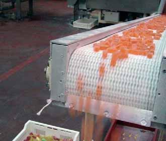
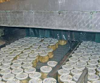
12 SERIES 20 SERIES 20 FLAT TOP Pitch Surface 20 mm Flat Top Open area 0% Thickness Drive system Belt width Advised minimum width Rod diameter Retention system 10 mm Central Multiples of 8 mm 120 mm Ø 4.6 mm Cap the belt the rod Belt strength (kg/m) Temperature range (ºC) Belt weight (kg/m 2 ) Available colours in stock Polypropylene Polypropylene 1, to white - grey Polyethylene Polyethylene to natural Polyacetal Polypropylene 2, to blue - Metal detectors - Reject by weight control - Magnetic elevators - Plastic film wrapping - Accumulation tables Thanks to its closed surface, it is the suitable belt for all those applications in which it is not necessary any drainage through the belt and / or the product to be transported is small. Its completely flat surface avoids the falls of product and the resulting blockage of the line. 11
 Open area 32% Thickness Drive system Belt width Advised minimum width Rod diameter Retention system Temperature range (ºC) Belt weight (kg/m 2 ) 9 mm Central Multiples of 8 mm 120 mm")

13 SERIES 20 SERIES 20 FLUSH GRID INFO Pitch Surface 20 mm Flush Grid the belt the rod - Metal detectors - Drying tunnels - Selection tables - Casing - Sewage filter - Loaders of tunnel ovens Belt strength (kg/m) Open area 32% Thickness Drive system Belt width Advised minimum width Rod diameter Retention system Temperature range (ºC) Belt weight (kg/m 2 ) 9 mm Central Multiples of 8 mm 120 mm Ø 4.6 mm Cap Available colours in stock Polypropylene Polypropylene 1, to white - grey Polyethylene Polyethylene to natural Polyacetal Polypropylene 2, to blue It has a grille-shaped configuration, with a 32% of open area and a surface completely smooth. It is ideal for applications in which a drainage through the belt is needed, avoiding any accumulation of particles on its surface. It implies an easier cleaning due to the possibility of applying water under pressure through the belt. 12 DATA A24 20 INDUSTRY
 Temperature range (ºC) Belt weight (kg/m 2 ) Available colours in stock Polypropylene Polypropylene 1,000 +1 to +104 6.")

14 SERIES 20 SERIES 20 RAISED RIB Pitch Surface 20 mm Raised Rib Open area 32% Thickness Drive system Belt width Advised minimum width Rod diameter Retention system 15 mm Central Multiples of 8 mm 120 mm Ø 4.6 mm Cap the belt the rod Belt strength (kg/m) Temperature range (ºC) Belt weight (kg/m 2 ) Available colours in stock Polypropylene Polypropylene 1, to grey Polyacetal Polypropylene 2, to blue It has been designed to make transferences of product by using finger plates. - Metal detectors - Casing - Sewage filter - Accumulation tables - Cooling lines With a grille-shaped configuration, and a 32% of open area, it is suitable for applications needing a drainage through the belt and/or a smaller surface of contact with the product. 13
 Belt with modules manufactured in a special thermo-rubber, with unbeatable characteristics of friction that enables")

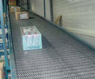
15 SERIES 20 SERIES 20 FRICTION TOP INFO Pitch Surface 20 mm Friction Top Surface of the belt the belt the rod - Non-slip conveyors - Aerial transport and distribution of boxes - Elevators Drive system Belt width Advised minimum width Rod diameter Retention system Belt strength (kg/m) Belt with modules manufactured in a special thermo-rubber, with unbeatable characteristics of friction that enables to do elevating and/or descending conveyors with maximum inclinations. Hardness SHORE A 64. Temperature range (ºC) Central Multiples of 8 mm 120 mm Ø 4.6 mm Cap Available colours in stock Flat Top Polypropylene Polypropylene 1, to +103 white - grey Flat Top Polyethylene Polyethylene to +65 natural Flat Top Polyacetal Polypropylene 2, to +90 blue Flush Grid Polypropylene Polypropylene 1, to +103 white - grey Flush Grid Polyethylene Polyethylene to +65 natural Flush Grid Polyacetal Polypropylene 2, to +90 blue 14 DATA A24 20 INDUSTRY


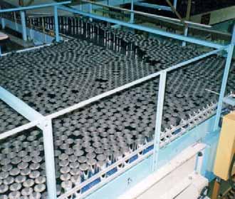
16 SERIES 20 SERIES 20 SLIDING ROLLERS Pitch Surface Drive system Belt width Advised minimum width Rod diameter Retention system Diameter of small roller Width of small roller small roller 20 mm Sliding Rollers Central Multiples of 8 mm 120 mm Ø 4.6 mm Cap Ø 15 mm 4,9 mm Polyacetal Surface the belt the rod Belt strength (kg/m) Temperature range (ºC) Available colours in stock Flush Grid Polypropylene Polypropylene 1, to +90 white - grey Flush Grid Polyethylene Polyethylene to +65 natural Flush Grid Polyacetal Polypropylene 2, to +90 blue The small rollers inserted on its surface, that revolve whenever there is accumulation, avoid crushing and damages in the base of the product. This belt has been designed mainly to solve problems of transport of boxes, containers, etc. 15

17 SERIES 20 SERIES 20 TRIAN INFO Pitch Surface 20 mm Trian Surface the belt the rod Drive system Belt width Advised minimum width Rod diameter Belt strength (kg/m) Temperature range (ºC) Central Multiples of 8 mm 120 mm Ø 4.6 mm Available colours in stock Flat Top Polyethylene Polyethylene to +65 natural Flush Grid Polyethylene Polyethylene to +65 natural - Liquid injection machines - Elevation to acid towers - Icing of frozen products - Freezing tunnels With its pitch of 20 mm, we can make transferences of small diameter. It has two transversal edges from side to side of the belt in order to prevent the product from sticking to the belt. 16 DATA A24 20 INDUSTRY


18 SERIES 20 SPROCKETS Hub width Nº of teeth T Pitch Ø mm Bore inch Hub width Materials Polypropylene Polyacetal Stainless steel We have plastic sprockets for round shaft with and without keyway. We also have sprockets to be used with motor drum in applications needing a special cleaning or in conveyors in which it is not possible to place the motor in the outside due to problems of space or safety. RETAINING RINGS The fastening of the central sprocket is made by retaining rings manufactured in AISI-316 stainless steel. Their design allows an easy installation without dismatling or grooving the shaf. They are fastened through a screw that remains perfectly fixed in the ring. Bore Screws 20 M 5 x 5 40 M 6 x 6 60 M 6 x 6 17
19 SERIES 20 DESIGN DATA A B C When building conveyors you should respect the distances appearing in the table depending on the sprocket size: Pitch Ø Distance between the sliding surface of the belt and the centre of the shaft. Distance between the vertical of the shaft and the beginning of the sliding surface. Distance between the sliding surface of the belt and the support of the return way. INSTALLATION A B max. C max You must put 1 sprocket in the middle fastened with 2 retaining rings. Then you should put the same quantity of sprockets, without any fastening, at each side of that central sprocket. You should proceed the same way in both shafts. To calculate the necessary minimum quantity of sprockets for the drive shaft as well as for the idle one, the next formula has been used: Minimum quantity: This quantity must always be odd. Belt width (mm) 70 mm DATA A24 20 INFO 18 INDUSTRY

20 SERIES 20 FLIGHTS AND SIDE GUARDS 90º RIGHT FLIGHT Accessories h Materials 90º right flight Polypropylene Polyethylene Polyacetal Side guards 50 Polypropylene Polyethylene Polyacetal The flights are plastic accessories to be inserted across the belt. They are used to push the product in ascent, descent or accompaniment applications, avoiding that it slips along the belt. SIDE GUARDS The side guards are plastic accessories to be inserted into the belt structure to retain the product laterally, avoiding overflows and frictions with the conveyor structure itself. It is possible to cut down the standard height for special applications. 19
21 SERIES 20 BELT ONLY WITH FLIGHTS BELT WITH FLIGHTS AND SIDE GUARDS The distance between the side edges of the belt and the flights (indent) must be a multiple of 8 mm, being 16 mm the minimum. The pitch of flights in Series 20 has to be a multiple of 40 mm. If the belt has both Flights and Side Guards, the minimum distance between them (A) will be: - 8 mm if the indent is a multiple of 8 (minimum indent to be 16 mm) - 4 mm if the indent is a multiple of 8 mm + 4 (minimum indent to be 20 mm) DATA A24 20 INFO 20 INDUSTRY

22 SERIES 20 FINGER PLATES Materials Colours Nº of teeth Nº of holes Screw dimension Nylon Polyacetal Black Grey x 19 They have been designed to be used with the Raised Rib belt in applications of intersection of lines in which it is necessary to transfer the product by means of finger plates. DESIGN DATA The finger plates are manufactured in nylon and have 13 teeth. These teeth couple perfectly among the projecting ribs of the belt, allowing the constant flow of product as the belt is engaged. They avoid the use of conventional dead plates and consequently the problems by stumbling and fall of the product. They have two fastening holes that enable little displacements to achieve a better coupling with the belt. Those holes are located so that they reduce to the minimum the vibrations owing to the turn of the belt over the sprockets. INSTALLATION The finger plates can be easily installed in the structure of the conveyor putting a screw in each hole. The dimensions of these screws are: M 6 x 19 mm. 21

23 SERIES 20 HOLD-DOWN PROFILES AND WEARSTRIPS PROFILES IN L INFO To make the fastening and the support of the belt, EUROBELT has designed two types of hold-down profiles with different geometries, but with the same uses and services. These profiles, with a low coefficient of friction, are placed between the belt and the structure of the conveyor, reducing the wear of the surfaces in contact, which contributes to prolong the life of the belt. EUROBELT offers all the hold-down profiles in special polyethylenes with very good sliding properties and an excellent resistance to impact. The flat wearstrips are fastened by means of flatheaded plastic screws, which contributes to obtain a smooth surface free of any possibility of hooking. The dimensions of those screws are: M 6 x 25 mm. Due to their dovetail design, they can adapt to possible longitudinal contractions and expansions of the belt. With regard to the wearstrips arrangement, you should choose an appropriate configuration according to the transport requirements. The distance between supports should not exceed 180 mm in the transport way or 200 mm in the return way. PROFILES IN U WEARSTRIPS Accessories Dimensions Materials Profiles in L Profiles in U 40 X 20 X 2, X 12 X 2, X 30 X 2, X 14 X 2,000 Polyethylene Polyethylene DATA A24 20 Wearstrips 6 x 32 x 500 Polyacetal Polyethylene Conductive polyethylene 22 INDUSTRY


24 SERIES 20 TABLE OF SPROCKETS AND WEARSTRIPS Belt nominal width (mm) Minimum quantity of sprockets per shaft Minimum quantity of wearstrips Transport way Return way , ,051 1, ,191 1, ,331 1, ,471 1, ,611 1, ,751 1, ,891 2, ,031 2, ,171 2, ,311 2, ,451 2, ,591 2, ,731 2, ,871 3, ,011 3, ,151 3, ,291 3, ,431 3, ,571 3, ,711 3, ,851 3, To calculate the minimum quantity of sprockets required both in the drive shaft and in the idle one, you should divide the belt width (in mm) by 70 mm. This amount must always be odd. To calculate the quantity of supports, the weight of the product to be transported must be taken into account. The distance between supports should not exceed 180 mm in the transport way or 200 mm in the return way. 23


25 Pitch Drive system Belt width Widths with one module Advised minimum width Rod diameter 24 mm Central Multiples of 10 mm Up to 200 mm 150 mm Ø 4.6 mm FLAT TOP FLUSH GRID RAISED RIB Two of the most important concerns in the conveyor belts market are: getting a safe traction as well as an easy cleaning. At EUROBELT we have developed the new SERIES A24 which fulfils with accuracy both technological challenges: A bigger opening of the links in the turns avoids the retention or accumulation of dirtiness. The completely smooth back side of the belt enables to take water and dirtiness to the edges in an easy and quick way. The completely open ends increase the efficiency in cleaning and allows to work in the best sanitary conditions. The teeth of the sprockets have two parts clearly different. The drive part, where the tooth is directly in contact with both faces of the module providing the suitable traction, and the transversal stoppage part that avoids movements of the sprocket along the shaft. SERIES A24


26 SERIES A24 SERIES A24 FLAT TOP Pitch Surface 24 mm Flat Top Open area 0% Thickness Drive system Belt width Widths with one module Advised minimum width Rod diameter Retention system 11 mm Central Multiples of 10 mm Up to 200 mm 150 mm Ø 4.6 mm Cap the belt the rod Belt strength (kg/m) Temperature range (ºC) Belt weight (kg/m 2 ) Available colours in stock Polypropylene Polypropylene 1, to white - blue - grey Polyethylene Polyethylene to natural - blue Polyacetal Polypropylene 2, to natural - blue Polyacetal Polyethylene 1, to natural - blue - Control and inspection - Metal detectors - Accumulation tables - Bottles feeding - Plastic film wrapping The completely smooth back side of the belt enables to take water and dirtiness to the edges quickly and easily. Its ends are totally opened which increases the efficiency when cleaning and allows working in the best sanitary conditions. A bigger opening of the links in the turns avoids the retention or accumulation of dirtiness. 25
 Open area 30% Thickness Drive system Belt width Widths with one module Advised minimum width Rod diameter Retention system Temperature range (ºC) Belt weight (kg/m 2 ) 11 mm Central")
27 SERIES A24 SERIES A24 FLUSH GRID INFO Pitch Surface 24 mm Flush Grid the belt the rod - Drying tunnels - Loaders of tunnel ovens - Selection tables - Casing - Washers - Defreezing applications Belt strength (kg/m) Open area 30% Thickness Drive system Belt width Widths with one module Advised minimum width Rod diameter Retention system Temperature range (ºC) Belt weight (kg/m 2 ) 11 mm Central Multiples of 10 mm Up to 200 mm 150 mm Ø 4.6 mm Cap Available colours in stock Polypropylene Polypropylene to white - blue - grey Polyethylene Polyethylene to natural - blue Polyacetal Polypropylene 1, to natural - blue Polyacetal Polyethylene 1, to natural - blue Its oval holes of 9.5 x 3 mm provide a 30% of open area. It is used for applications involving drainage of liquids or passage of air through the belt, for drying or unfreezing of products. 26 DATA A24 20 INDUSTRY


28 SERIES A24 SERIES A24 RAISED RIB Pitch Surface 24 mm Raised Rib Open area 30% Contact area 32% Thickness Drive system Belt width Widths with one module Advised minimum width Rod diameter Retention system 17 mm Central Multiples of 10 mm Up to 200 mm 150 mm Ø 4.6 mm Cap the belt the rod Belt strength (kg/m) Temperature range (ºC) Belt weight (kg/m 2 ) Available colours in stock Polypropylene Polypropylene to grey Polyacetal Polypropylene 1, to blue Polyacetal Polyethylene 1, to blue This belt has been designed mainly to be used with finger plates. - Palletisers and depalletisers - Icing of frozen products - Cooling lines - Accumulation tables The ribs that rise up 6 mm over the module are interlaced so that they provide a greater resistance as well as a better sliding conditions for the product. 27


29 SERIES A24 DATA A24 20 INFO 28 INDUSTRY

30 SERIES A24 SPROCKETS Hub width Nº of teeth T Pitch Ø mm Bore inch Hub width Materials Polypropylene Polyacetal Stainless steel Drive direction We have plastic sprockets for round shaft with and without keyway. We also have sprockets to be used with motor drum in applications needing a special cleaning or in conveyors in which it is not possible to place the motor in the outside due to problems of space or safety. RETAINING RINGS The fastening of the central sprocket is made by retaining rings manufactured in AISI-316 stainless steel. Their design allows an easy installation without dismantling or grooving the shaft. They are fastened through a screw that remains perfectly fixed in the ring. Bore Screws 20 M 5 x 5 40 M 6 x 6 60 M 6 x 6 90 M 6 x 6 29
31 SERIES A24 DESIGN DATA A B C INSTALLATION In the building of conveyors, the distances appearing in the table should be respected depending on the sprocket size: Pitch Ø Distance between the sliding surface of the belt and the centre of the shaft. Distance between the vertical of the shaft and the beginning of the sliding surface. Distance between the sliding surface of the belt and the support of the return way. You must put 1 sprocket in the middle fastened with 2 retaining rings. Then you should put the same quantity of sprockets, without any fastening, at each side of that central sprocket. You should proceed the same way in both shafts. To calculate the necessary minimum quantity of sprockets for the drive shaft as well as for the idle one, the next formula has been used: Minimum quantity: This quantity must always be odd. A B max. Belt width (mm) 100 mm C max DATA A24 20 INFO 30 INDUSTRY

32 SERIES A24 FLIGHTS AND SIDE GUARDS 90º RIGHT FLIGHT Accessories h Materials 90º right flight Polypropylene Polyethylene Polyacetal Side guards 50 Polypropylene Polyethylene Polyacetal The flights are plastic accessories to be inserted across the belt. They are used to push the product in ascent, descent or accompaniment applications, avoiding that it slips along the belt. SIDE GUARDS The side guards are plastic accessories to be inserted into the belt structure to retain the product laterally, avoiding overflows and frictions with the conveyor structure itself. It is possible to cut down the standard height for special applications. 31
33 SERIES A24 BELT ONLY WITH FLIGHTS BELT WITH FLIGHTS AND SIDE GUARDS The distance between the side edges of the belt and the flights (indent) must be a multiple of 10 mm, being 20 mm the minimum. The pitch of flights along the belt will be a multiple of 48 mm. If the belt has both Flights and Side Guards, the minimum distance between them (A) will be: - 10 mm if the indent is a multiple of 10 mm - 5 mm if the indent is a multiple of 10 mm + 5 DATA A24 20 INFO 32 INDUSTRY

34 SERIES A24 FINGER PLATES Materials Colours Nº of teeth Nº of holes Screw dimension Nylon Polyacetal Black Grey x 19 They have been designed to be used with the Raised Rib belts in applications in which it is necessary to transfer the product by means of finger plates. DESIGN DATA The finger plates are manufactured in nylon and have 15 teeth. These teeth couple perfectly among the projecting ribs of the belt, allowing the constant flow of product as the belt is engaged. They avoid the use of conventional dead plates and consequently the problems by stumbling and fall of the product. They have three fastening holes that enable little displacements to achieve a better coupling with the belt. INSTALLATION Those holes are located so that they reduce to the minimum the vibrations owing to the turn of the belt over the sprockets. The finger plates can be easily installed in the structure of the conveyor putting a screw in each hole. The dimensions of these screws are: M 6 x 19 mm. 33
35 SERIES A24 HOLD-DOWN PROFILES AND WEARSTRIPS PROFILES IN L INFO To make the fastening and the support of the belt, EUROBELT has designed two types of hold-down profiles, with different geometries, but with the same uses and services. These profiles, with a low coefficient of friction, are placed between the belt and the structure of the conveyor, reducing the wear of the surfaces in contact, which contributes to prolong the life of the belt. EUROBELT offers all the hold-down profiles in special polyethylenes, with very good sliding properties and an excellent resistance to impact. The flat wearstrips are fastened by means of flatheaded plastic screws, which contributes to obtain a smooth surface free of any possibility of hooking. The dimensions of those screws are: M 6 x 25 mm. Due to their dovetail design, they can adapt to possible longitudinal contractions and expansions of the belt. With regard to the wearstrips arrangement, you should choose an appropriate configuration according to the transport requirements. The distance between supports should not exceed 180 mm in the transport way or 200 mm in the return way. PROFILES IN U WEARSTRIPS Accessories Dimensions Materials Profiles in L Profiles in U 40 X 20 X 2, X 12 X 2, X 30 X 2, X 14 X 2,000 Polyethylene Polyethylene DATA A24 20 Wearstrips 6 x 32 x 500 Polyacetal Polyethylene Conductive polyethylene 34 INDUSTRY
36 SERIES A24 TABLE OF SPROCKETS AND WEARSTRIPS Belt nominal width (mm) Minimum quantity of sprockets per shaft Minimum quantity of wearstrips Transport way Return way , ,101 1, ,301 1, ,501 1, ,701 1, ,901 2, ,101 2, ,301 2, ,501 2, ,701 2, ,901 3, ,101 3, ,301 3, ,501 3, ,701 3, ,901 4, To calculate the minimum quantity of sprockets required both in the drive shaft and in the idle one, you should divide the belt width (in mm) by 100 mm. This amount must always be odd To calculate the quantity of supports, the weight of the product to be transported must be taken into account. The distance between supports should not exceed 180 mm in the transport way or 200 mm in the return way. 35


37 Pitch Drive system Belt width Advised minimum width Rod diameter 30 mm Central Multiples of 10 mm 150 mm Ø 4.6 mm FLAT TOP PERFORATED FLUSH GRID RAISED RIB SLIDING ROLLERS SERIES 30
 Temperature range (ºC) Belt weight (kg/m 2 ) Available colours in stock Polypropylene Polypropylene 1,100 +1 to +104 5.")
38 SERIES 30 SERIES 30 FLAT TOP Pitch Surface 30 mm Flat Top Open area 0% Thickness Drive system Belt width Advised minimum width Rod diameter Retention system 10 mm Central Multiples of 10 mm 150 mm Ø 4.6 mm Cap the belt the rod Belt strength (kg/m) Temperature range (ºC) Belt weight (kg/m 2 ) Available colours in stock Polypropylene Polypropylene 1, to white - grey - blue Polyethylene Polyethylene to natural Polyacetal Polypropylene 2, to blue - Control and inspection - High speed lines - Accumulation tables - Bottles feeding - Elevators of residues - Packaging lines With a closed surface, it is the suitable belt for all those applications in which it is not necessary any drainage through the belt and / or the product to be transported is small. Its completely flat surface avoids the falls of product and the resulting blockage of the line. 37
 Belt weight (kg/m 2 ) 10 mm 2 x 5 mm - 2 x 8 mm Central Multiples of 10 mm 150 mm Ø 4.")

39 SERIES 30 SERIES 30 PERFORATED FLAT TOP INFO Pitch Surface 30 mm Perforated Flat Top the belt the rod Belt strength (kg/m) Open area 17% Thickness Dimensions of openings Drive system Belt width Advised minimum width Rod diameter Retention system Temperature range (ºC) Belt weight (kg/m 2 ) 10 mm 2 x 5 mm - 2 x 8 mm Central Multiples of 10 mm 150 mm Ø 4.6 mm Cap Available colours in stock Polypropylene Polypropylene 1, to white - grey Polyethylene Polyethylene to natural Polyacetal Polypropylene 2, to blue With a 17% open area, it has a completely smooth surface with small, straight, and grille-shaped openings without structural obstacles. This is the suitable belt for applications needing a drainage through the belt and in which the product to be transported is small. DATA A INDUSTRY
 Temperature range (ºC) Belt weight (kg/m 2 ) Available colours in stock Polypropylene Polypropylene 1,100 +1 to +104 3.")

40 SERIES 30 SERIES 30 FLUSH GRID Pitch 30 mm Surface Flush Grid Open area 41% Thickness 9 mm Drive system Central Belt width Multiples of 10 mm Advised minimum width 150 mm Rod diameter Ø 4.6 mm Retention system Cap the belt the rod Belt strength (kg/m) Temperature range (ºC) Belt weight (kg/m 2 ) Available colours in stock Polypropylene Polypropylene 1, to white - grey Polyethylene Polyethylene to natural Polyacetal Polypropylene 2, to blue It has a grille-shaped configuration, with a 41% of open area and a completely smooth surface. - Tyre production lines - Defreezing - Washers - Turning round of boxes It is ideal for applications in which it is needed a drainage through the belt, avoiding any accumulation of particles on its surface. The cleaning by applying air or water under pressure through the belt is very easy. 39
 Belt weight (kg/m 2 ) Raised Rib 15 mm Central Multiples of 10 mm 150 mm Ø 4.")

41 SERIES 30 SERIES 30 RAISED RIB the belt the rod - Casing - Coolers - Palletisers and depalletisers - Icing of frozen products - Plastic film wrapping Belt strength (kg/m) Pitch Surface 30 mm Open area 41% Thickness Drive system Belt width Advised minimum width Rod diameter Retention system Temperature range (ºC) Belt weight (kg/m 2 ) Raised Rib 15 mm Central Multiples of 10 mm 150 mm Ø 4.6 mm Cap Available colours in stock Polypropylene Polypropylene 1, to grey Polyacetal Polypropylene 2, to blue It has been designed to transfer products by means of finger plates. Thanks to its even, ribbed surface it is recommended for accumulation of containers of uncertain stability when it is necessary the use of finger plates. 40 DATA A24 20 INFO INDUSTRY


42 SERIES 30 SERIES 30 SLIDING ROLLERS Pitch Surface Drive system Belt width Advised minimum width Rod diameter Retention system Diameter of small roller Width of small roller small roller 30 mm Sliding Rollers Central Multiples of 10 mm 150 mm Ø 4.6 mm Cap Ø 15 mm 4,9 mm Polyacetal Surface the belt the rod Belt strength (kg/m) Temperature range (ºC) Available colours in stock Flush Grid Polypropylene Polypropylene 1, to +90 white - grey Flush Grid Polyethylene Polyethylene to +65 natural Flush Grid Polyacetal Polypropylene 2, to +90 blue The small rollers inserted on its surface, that revolve whenever there is accumulation, avoid crushing and damages in the base of the product. It has been designed mainly to solve problems of transport of boxes, containers, etc. 41


43 SERIES 30 DATA A24 20 INFO 42 INDUSTRY

44 SERIES 30 SPROCKETS Hub width Nº of teeth T Pitch Ø mm Bore inch Hub width Materials Polypropylene Polyacetal Stainless steel We have plastic sprockets for round shaft with and without keyway. We also have sprockets to be used with motor drum in applications needing a special cleaning or in conveyors in which it is not possible to place the motor in the outside due to problems of space or safety. RETAINING RINGS The fastening of the central sprocket is made by retaining rings manufactured in AISI-316 stainless steel. Their design allows an easy installation without dismatling or grooving the shaft. They are fastened through a screw that remains perfectly fixed in the ring. Bore Screws 25 M 5 x 5 40 M 6 x 6 60 M 6 x 6 90 M 6 x 6 43
45 SERIES 30 DESIGN DATA A B C INSTALLATION In the building of conveyors, the distances appearing in the table should be respected depending on the sprocket size: Pitch Ø Distance between the sliding surface of the belt and the centre of the shaft. Distance between the vertical of the shaft and the beginning of the sliding surface. Distance between the sliding surface of the belt and the support of the return way. You must put 1 sprocket in the middle fastened with 2 retaining rings. Then you should put the same quantity of sprockets, without any fastening, at each side of that central sprocket. You should proceed the same way in both shafts. To calculate the necessary minimum quantity of sprockets for the drive shaft as well as for the idle one, the next formula has been used: Minimum quantity: This quantity must always be odd. A B max. Belt width (mm) 100 mm C max DATA A24 20 INFO 44 INDUSTRY

46 SERIES 30 FLIGHTS AND SIDE GUARDS 90º RIGHT FLIGHT Accessories h Materials 90º right flight Polypropylene Polyethylene Polyacetal Side guards 50 Polypropylene Polyethylene Polyacetal The flights are plastic accessories to be inserted across the belt. They are used to push the product in ascent, descent or accompaniment applications, avoiding that it slips along the belt. SIDE GUARDS The side guards are plastic accessories to be inserted into the belt structure to retain the product laterally, avoiding overflows and frictions with the conveyor structure itself. It is possible to cut down the standard height for special applications. 45
47 SERIES 30 BELT ONLY WITH FLIGHTS BELT WITH FLIGHTS AND SIDE GUARDS The distance between the side edges of the belt and the flights (indent) must be a multiple of 10 mm, being 20 mm the minimum. The pitch of flights along the belt will be a multiple of 60 mm. If the belt has both Flights and Side Guards, the minimum distance between them (A) will be: - 10 mm if the indent is a multiple of 10 mm (minimum indent to be 20 mm) - 5 mm if the indent is a multiple of 10 mm + 5 (minimum indent to be 25 mm) DATA A24 20 INFO 46 INDUSTRY
48 SERIES 30 FINGER PLATES Materials Colours Nº of teeth Nº of holes Screw dimension Nylon Polyacetal Black Grey x 19 They have been designed to be used with the Raised Rib belts in applications in which it is necessary to transfer the product by means of finger plates. DESIGN DATA The finger plates are manufactured in nylon and have 15 teeth. These teeth couple perfectly among the projecting ribs of the belt, allowing the constant flow of product as the belt is engaged. They avoid the use of conventional dead plates and consequently the problems by stumbling and fall of the product. They have three fastening holes that enable little displacements to achieve a better coupling with the belt. INSTALLATION Those holes are located so that they reduce to the minimum the vibrations owing to the turn of the belt over the sprockets. The finger plates can be easily installed in the structure of the conveyor putting a screw in each hole. The dimensions of these screws are: M 6 x 19 mm. 47

49 SERIES 30 HOLD-DOWN PROFILES AND WEARSTRIPS PROFILES IN L INFO To make the fastening and the support of the belt, EUROBELT has designed two types of hold-down profiles, with different geometries, but with the same uses and services. These profiles, with a low coefficient of friction, are placed between the belt and the structure of the conveyor, reducing the wear of the surfaces in contact, which contributes to prolong the life of the belt. EUROBELT offers all the hold-down profiles in special polyethylenes, with very good sliding properties and an excellent resistance to impact. The flat wearstrips are fastened by means of flatheaded plastic screws, which provides a smooth surface free of any possibility of hooking. The dimensions of those screws are: M 6 x 25 mm. Due to their dovetail design, they can adapt to possible longitudinal contractions and expansions of the belt. With regard to the wearstrips arrangement, you should choose an appropriate configuration according to the transport requirements. The distance between supports should not exceed 180 mm in the transport way or 200 mm in the return way. PROFILES IN U WEARSTRIPS Accessories Dimensions Materials Profiles in L Profiles in U 40 X 20 X 2, X 12 X 2, X 30 X 2, X 14 X 2,000 Polyethylene Polyethylene DATA A24 20 Wearstrips 6 x 32 x 500 Polyacetal Polyethylene Conductive polyethylene 48 INDUSTRY

50 SERIES 30 TABLE OF SPROCKETS AND WEARSTRIPS Belt nominal width (mm) Minimum quantity of sprockets per shaft Minimum quantity of wearstrips Transport way Return way , ,101 1, ,301 1, ,501 1, ,701 1, ,901 2, ,101 2, ,301 2, ,501 2, ,701 2, ,901 3, ,101 3, ,301 3, ,501 3, ,701 3, ,901 4, To calculate the minimum quantity of sprockets required both in the drive shaft and in the idle one, you should divide the belt width (in mm) by 100 mm. This amount must always be odd To calculate the quantity of supports, the weight of the product to be transported must be taken into account. The distance between supports should not exceed 180 mm in the transport way or 200 mm in the return way. 49


51 Pitch Lower guides Drive system Belt width - Series 31 Belt width - Series 32 Rod diameter 30 mm 8 mm Central 152,4 mm 82,5-114,3-152,4-190,5 mm Ø 4.6 mm LATERAL TRANSFER FLAT TOP The EUROBELT belts of only one module are more noiseless and lighter than the chain lines. Their maintenance is considerably reduced as it is not necessary the use of any type of lubricant to obtain a good performance. Lateral transfer without accidental falls caused by overturning - No need to use any transfer element - Better stability and excellent movement of containers Maximum resistance in the accumulation of containers - Avoids damages on the containers' surface High speed lines with no need of using lubrication - Better working conditions - Considerable reduction of costs - No more problems with wet containers Lower guides SERIES 31-32
 the belt the rod Belt strength (kg/m) Temperature range (ºC) Lineal meter weight (kg) 152.4 Acetal Polypropylene 2,250 +1 to +90 1.")
52 SERIES SERIES 31 LATERAL TRANSFER Pitch Surface 30 mm Flat Top Open area 0% Thickness 10 mm Lower guides 8 mm Drive system Central Belt width 152,4 mm Rod diameter Ø 4.6 mm Retention system Cap Belt width (mm) the belt the rod Belt strength (kg/m) Temperature range (ºC) Lineal meter weight (kg) Acetal Polypropylene 2, to Belt with a 30 mm pitch and with one-only-piece geometry, mm wide. It has one of its edges bevelled, to make easier the approach to the belt delivering the product, and lower guides in order to assure its alignment. It has been designed to make lateral dynamic transferences of containers in perpendicular intersections of lines. 51
 Temperature range (ºC) 10 mm 8 mm Central Ø 4.6 mm Cap Lineal meter weight (kg) 82.5 Polyacetal Polypropylene 2,250 +1 to +90 0.70 114.")

53 SERIES SERIES 32 FLAT TOP Pitch Surface 30 mm Flat Top INFO Belt width (mm) the belt the rod Open area 0% Thickness Lower guides Drive system Rod diameter Retention system Belt strength (kg/m) Temperature range (ºC) 10 mm 8 mm Central Ø 4.6 mm Cap Lineal meter weight (kg) 82.5 Polyacetal Polypropylene 2, to Polyacetal Polypropylene 2, to Polyacetal Polypropylene 2, to Polyacetal Polypropylene 2, to Belt with 30 mm pitch and with a geometry of only one part in different widths: 82,5 114,3 152,4 190,5 mm. It has two lower guides to keep the belt aligned by counteracting the side forces. DATA A INDUSTRY

54 SERIES SPROCKETS Hub width Nº of teeth T Pitch Ø mm Bore inch Hub width Materials Polypropylene Polyacetal Stainless steel We have plastic sprockets for round shaft with and without keyway. We also have sprockets to be used with motor drum in applications needing a special cleaning or in conveyors in which it is not possible to place the motor in the outside due to problems of space or safety. RETAINING RINGS The fastening of the central sprocket is made by retaining rings manufactured in AISI-316 stainless steel. Their design allows an easy installation without dismantling or grooving the shaft. They are fastened through a screw that remains perfectly fixed in the ring. Bore Screws 25 M 5 x 5 40 M 6 x 6 60 M 6 x 6 90 M 6 x 6 53
55 SERIES DESIGN DATA A B C INSTALLATION In the building of conveyors, the distances appearing in the table should be respected depending on the sprocket size: Ø Pitch Distance between the sliding surface of the belt and the centre of the shaft. Distance between the vertical of the shaft and the beginning of the sliding surface. Distance between the sliding surface of the belt and the support of the return way. A B max. C max You must put 1 sprocket in the middle fastened with 2 retaining rings. Then you should put the same quantity of sprockets, without any fastening, at each side of that central sprocket. You should proceed the same way in both shafts. DATA A24 20 INFO 54 INDUSTRY
56 SERIES TRANSFERENCES WITH BELT By using the Series 31 Lateral-Transfer Flat Top, dynamic and smooth lateral transferences can be carried out with no need of finger plates. With one of its edges bevelled we manage to bring nearer the belts taking part in the transference, whereas the lower guides keep the belt aligned. It has been designed for those applications in which we want to avoid the retention of containers in the transference area as well as to achieve more efficiency in their movement. 55


57 Pitch Drive system Belt width Advised minimum width Rod diameter 40 mm Central Multiples of 10 mm 150 mm Ø 6 mm FLAT TOP FLUSH GRID RAISED RIB SLIDING ROLLERS NON SLIP SERIES 40-41
 Temperature range (ºC) Belt weight (kg/m 2 ) Available colours in stock Polypropylene Polypropylene 3,600 +1 to")

58 SERIES SERIES 40 FLAT TOP Pitch Surface 40 mm Flat Top Open area 0% Thickness Drive system Belt width Widths with one module Advised minimum width Rod diameter Retention system 16 mm Central Multiples of 10 mm Up to 200 mm 150 mm Ø 6 mm Cap the belt the rod Belt strength (kg/m) Temperature range (ºC) Belt weight (kg/m 2 ) Available colours in stock Polypropylene Polypropylene 3, to white - grey Polyethylene Polyethylene 2, to natural Polyacetal Polypropylene 4, to blue With a closed surface, it is the suitable belt for all those applications not needing any drainage through the belt and / or in which the product to be transported is small. - Positioning for welding - Transport of delicate pieces - Accumulation of containers - Swan-necked elevators Its great mechanical resistance make it be ideal for applications having big transport lengths or bearing very heavy loads. 57
 Belt weight (kg/m 2 ) 16 mm Central Multiples of 10 mm 150 mm Ø 6 mm Cap")

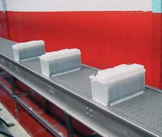
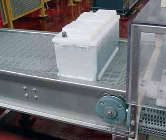
59 SERIES SERIES 40 FLUSH GRID INFO Pitch Surface 40 mm Flush Grid the belt the rod - Pasteurisers - Big accumulation tables - Charge of batteries - Degreasing applications Belt strength (kg/m) Open area 14% Thickness Drive system Belt width Advised minimum width Rod diameter Retention system Temperature range (ºC) Belt weight (kg/m 2 ) 16 mm Central Multiples of 10 mm 150 mm Ø 6 mm Cap Available colours in stock Polypropylene Polypropylene 3, to white - grey Polyethylene Polyethylene 2, to natural Polyacetal Polypropylene 4, to blue It has a grille-shaped configuration, with a 14% open area and a completely smooth surface. Owing to the specific study carried out, it is one of the strongest belts in the market, having an excellent capacity of drainage likewise. It is ideal for those applications in which a great belt resistance is required, for very long conveyors, and/or when there is a heavy load to be transported. 58 DATA A24 20 INDUSTRY
 Temperature range (ºC) Belt weight (kg/m 2 ) Available colours in stock Polypropylene Polypropylene 3,600 +1 to +104 12.")

60 SERIES SERIES 41 RAISED RIB Pitch Surface 40 mm Raised Rib Open area 25% Thickness Drive system Belt width Advised minimum width Rod diameter Retention system 22 mm Central Multiples of 10 mm 150 mm Ø 6 mm Cap the belt the rod Belt strength (kg/m) Temperature range (ºC) Belt weight (kg/m 2 ) Available colours in stock Polypropylene Polypropylene 3, to grey With a configuration of projecting ribs, it enables to make transferences of product by using finger plates. - Pasteurisers - Accumulation tables - Casing - Palletisers and depalletisers - Coolers The central reinforcement of the ribs allows the lateral entrance of cans, glass bottles or containers in general, avoiding their overturning as well as damages in the belt surface. 59
 Open area 0% Thickness Drive system Belt width Advised minimum width Rod diameter Retention system Temperature range (ºC) Belt weight (kg/m 2 ) 16 mm Central")

61 SERIES SERIES 40 NON SLIP INFO Pitch Surface 40 mm Non Slip the belt Conductive polypropylene - Non-slip conveyors - Transport of people - Transport of cars the cross rod Conductive polypropylene Belt strength (kg/m) Open area 0% Thickness Drive system Belt width Advised minimum width Rod diameter Retention system Temperature range (ºC) Belt weight (kg/m 2 ) 16 mm Central Multiples of 10 mm 150 mm Ø 6 mm Cap Available colours in stock 3, to black It has a closed surface with a new relief specially designed to avoid slips. It is very easy to clean even through industrial mechanical means. Its high resistance to traction and to chemical aggression of oils and industrial acids make it be the suitable belt for conveying people, for assembly lines in the car industry, for conveying furniture, electrical appliances, etc. DATA A INDUSTRY
 Temperature range (ºC) Available colours in stock Flush Grid")
62 SERIES SERIES 40 SLIDING ROLLERS Pitch Surface Drive system Belt width Advised minimum width Rod diameter Retention system Diameter of small roller Width of small roller small roller 40 mm Flush Grid Central Multiples of 10 mm 150 mm Ø 6 mm Cap Ø 25 mm 10 mm Polyacetal Surface the belt the rod Belt strength (kg/m) Temperature range (ºC) Available colours in stock Flush Grid Polypropylene Polypropylene 3, to +90 white - grey Flush Grid Polyethylene Polyethylene 2, to +65 natural Flush Grid Polyacetal Polypropylene 4, to +90 blue The small rollers inserted on its surface, that revolve whenever there is accumulation, avoid crushing and damages in the base of the product. It has been designed mainly to solve problems of transport of boxes, containers,... 61


63 SERIES DATA A24 20 INFO 62 INDUSTRY

64 SERIES SPROCKETS Hub width Nº of teeth T Pitch Ø mm Bore inch Hub width Materials Polypropylene Polycetal Stainless steel We have plastic sprockets for round shaft with and without keyway. We also have sprockets to be used with motor drum in applications needing a special cleaning or in conveyors in which it is not possible to place the motor in the outside due to problems of space or safety. RETAINING RINGS The fastening of the central sprocket is made through retaining rings manufactured in AISI-316 stainless steel. Their design allows an easy installation without dismantling or grooving the shaft. They are fastened through a screw that remains perfectly fixed in the ring. Bore Screws 40 M 6 x 6 60 M 6 x 6 90 M 6 x 6 63
65 SERIES DESIGN DATA A B C INSTALLATION In the building of conveyors, the distances appearing in the table should be respected depending on the sprocket size: Pitch Ø Distance between the sliding surface of the belt and the centre of the shaft. Distance between the vertical of the shaft and the beginning of the sliding surface. Distance between the sliding surface of the belt and the support of the return way. You must put 1 sprocket in the middle fastened with 2 retaining rings. Then you should put the same quantity of sprockets, without any fastening, at each side of that central sprocket. You should proceed the same way in both shafts. To calculate the necessary minimum quantity of sprockets for the drive shaft as well as for the idle one, the next formula has been used: Minimum quantity: This quantity must always be odd. A B max. Belt width (mm) 150 mm C max DATA A24 20 INFO 64 INDUSTRY

66 SERIES FLIGHTS AND SIDE GUARDS 90º RIGHT FLIGHT Accessories h Materials 90º right flight Polypropylene Polyethylene Polyacetal Bent flight on request Polypropylene Polyethylene Side guards Polypropylene Polyethylene Polyacetal BENT FLIGHT The flights are plastic accessories to be inserted across the belt. They are used to push the product in ascent, descent or accompaniment applications, avoiding that it slips along the belt. The side guards are plastic accessories to be inserted into the belt structure to retain the product laterally, avoiding overflows and frictions with the conveyor structure itself. It is possible to cut down the standard height for special applications. SIDE GUARDS 65
67 SERIES BELT ONLY WITH FLIGHTS BELT WITH FLIGHTS AND SIDE GUARDS The distance between the side edges of the belt and the flights (indent) must be a multiple of 10 mm, being 30 mm the minimum. The pitch of flights in Series 40 should be a multiple of 80 mm. If the belt has both Flights and Side Guards, the minimum distance between them (A) will be: - 10 mm if the indent is a multiple of 10 mm (minimum indent to be 30 mm) - 5 mm if the indent is a multiple of 10 mm + 5 (minimum indent to be 35 mm) DATA A24 20 INFO 66 INDUSTRY

68 SERIES FINGER PLATES Materials Colours Nº of teeth Nº of holes Screw dimension Nylon Polyacetal Black Grey x 19 They have been designed to be used with the Raised Rib belts in applications in which it is necessary to transfer the product by means finger plates. DESIGN DATA The finger plates are manufactured in nylon and have 15 teeth. These teeth couple perfectly among the projecting ribs of the belt, allowing the constant flow of product as the belt is engaged. They avoid the use of conventional dead plates and consequently the problems by stumbling and fall of the product. They have three fastening holes that enable little displacements to achieve a better coupling with the belt. INSTALLATION Those holes are located so that they reduce to the minimum the vibrations owing to the turn of the belt over the sprockets. The finger plates can be easily installed in the structure of the conveyor putting a screw in each hole. The dimensions of these screws are: M 6 x 19 mm. 67
69 SERIES HOLD-DOWN ROLLERS INFO They are used to fasten the belt to the conveyor in all the inflexions. In applications in which the belt must be submerged, they are placed in the middle of the belt to prevent it from getting bent due to the flotation. They will roll along rails fastened throughout the conveyor structure. It is recommended to place wearstrips to avoid the wear owing to rolling as far as possible. The distance between the side edge of the belt and the centre of the hold-down roller (indent) must be a multiple of 5 mm. Hold-down rollers cannot be used with the following sprockets: Nº of teeth T Bore DESIGN DATA DATA A INDUSTRY

70 SERIES HOLD-DOWN PROFILES AND WEARSTRIPS PROFILES IN L To make the fastening and the support of the belt, EUROBELT has designed two types of hold-down profiles, with different geometries, but with the same uses and services. PROFILES IN U These profiles, with a low coefficient of friction, are placed between the belt and the structure of the conveyor, reducing the wear of the surfaces in contact, which contributes to prolong the life of the belt. EUROBELT offers all the hold-down profiles in special polyethylenes, with very good sliding properties and an excellent resistance to impact. The flat wearstrips are fastened by means of flatheaded plastic screws, which provides a smooth surface free of any possibility of hooking. The dimensions of those screws are: M 6 x 25 mm. WEARSTRIPS Due to their dovetail design, they can adapt to possible longitudinal contractions and expansions of the belt. With regard to the wearstrips arrangement, you should choose an appropriate configuration according to the transport requirements. The distance between supports should not exceed 230 mm in the transport way or 300 mm in the return way. Accessories Dimensions Materials Profiles in L Profiles in U 40 X 20 X 2, X 12 X 2, X 30 X 2, X 14 X 2,000 Polyethylene Polyethylene Wearstrips 6 x 32 x 500 Polyacetal Polyethylene Conductive polyethylene 69

71 SERIES TABLE OF SPROCKETS AND WEARSTRIPS Belt nominal width (mm) Minimum quantity of sprockets per shaft Minimum quantity of wearstrips Transport way Return way , ,051 1, ,351 1, ,651 1, ,951 2, ,251 2, ,551 2, ,851 3, ,151 3, ,451 3, ,751 4, To calculate the minimum quantity of sprockets required both in the drive shaft and in the idle one, you should divide the belt width (in mm) by 150 mm. This amount must always be odd. To calculate the quantity of supports, the weight of the product to be transported must be taken into account. The distance between supports should not exceed 230 mm in the transport way or 300 mm in the return way. DATA A24 20 INFO 70 INDUSTRY

72 71 SERIES 40-41


73 Pitch Drive system Belt width Widths with one module Advised minimum width Rod diameter 50 mm HInge Multiples of 20 mm Up to 200 mm 40 mm Ø 6 mm FLAT TOP PERFORATED FLUSH GRID OPEN GRID KNURLED CONIC CONIC FRICTION FRICTION TOP SLIDING ROLLERS SERIES 50
 Temperature range (ºC) Belt weight (kg/m 2 ) Available colours in stock Polypropylene Polypropylene 1,800 +1 to")

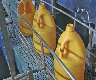
74 SERIES 50 SERIES 50 FLAT TOP Pitch Surface 50 mm Flat Top Open area 0% Thickness Drive system Belt width Widths with one module Advised minimum width Rod diameter Retention system 15,2 mm Hinge Multiples of 20 mm Up to 200 mm 40 mm Ø 6 mm Cap the belt the rod Belt strength (kg/m) Temperature range (ºC) Belt weight (kg/m 2 ) Available colours in stock Polypropylene Polypropylene 1, to white - grey Polyethylene Polyethylene 1, to natural - blue With a closed surface, completely flat and smooth, it avoids damages in the product and the blockage of the lines owing to overturning. - Chicken frames elevation - Swan-necked elevators - Metal detectors - Cheese moulds elevation - Boiling applications It is the belt most commonly used in elevating conveyors of products in bulk as well as in transport of delicate products. 73


75 SERIES 50 SERIES 50 PERFORATED FLAT TOP INFO Pitch Surface 50 mm Perforated Flat Top the belt the rod Belt strength (kg/m) - Disinfection, scalding and canning lines - Residues filters - Macerating and mixing applications - Transport lines in flooded pools - Boiling applications Open area 18% Thickness Dimensions of openings Drive system Belt width Widths with one module Advised minimum width Rod diameter Retention system Temperature range (ºC) Belt weight (kg/m 2 ) 15,2 mm 1.8 x 6-2 x 9-2 x 15 mm Hinge Multiples of 20 mm Up to 200 mm 40 mm Ø 6 mm Cap Available colours in stock Polypropylene Polypropylene 1, to white - grey Polyethylene Polyethylene 1, to natural -blue With an 18% open area, it has a completely flat grille-shaped surface, with small straight openings that have no structural obstacles. 74 DATA A24 20 INDUSTRY
 Temperature range (ºC) Belt weight (kg/m 2 ) Available colours in stock Polypropylene Polypropylene 2,400 +1 to")

76 SERIES 50 SERIES 50 FLUSH GRID Pitch Surface 50 mm Flush Grid Open area 40% Thickness Drive system Belt width Widths with one module Advised minimum width Rod diameter Retention system 16 mm Hinge Multiples of 20 mm Up to 200 mm 40 mm Ø 6 mm Cap the belt the rod Belt strength (kg/m) Temperature range (ºC) Belt weight (kg/m 2 ) Available colours in stock Polypropylene Polypropylene 2, to white - grey Polyethylene Polyethylene 1, to natural - blue It has a grille-shaped configuration, with a 40% open area and a completely smooth surface. - Degreasing applications - Boiling applications - Washers - Vacuum machines - Hydrocooling - Cheese presses - Drying ovens It is ideal for applications in which there are a lot of wastes left by the transported product, as their removal is very easy by means of air or water under pressure. It is specially recommended for cooling and / or freezing tunnels. 75
 Open area 40% Thickness Drive system Belt width Widths with one module Advised minimum width Rod diameter Retention system Temperature range (ºC) Belt weight")

77 SERIES 50 SERIES 50 OPEN GRID INFO Pitch Surface 50 mm Open Grid the belt the rod - Liquid injection machines - Elevation to acid towers - Defreezing applications - Icing of frozen products - Freezing tunnels Belt strength (kg/m) Open area 40% Thickness Drive system Belt width Widths with one module Advised minimum width Rod diameter Retention system Temperature range (ºC) Belt weight (kg/m 2 ) 16 mm Hinge Multiples of 20 mm Up to 200 mm 40 mm Ø 6 mm Stopper Available colours in stock Polypropylene Polypropylene 1, to white - grey Polyethylene Polyethylene 1, to natural - blue With a pitch of 50 mm, a grille-shaped configuration, and a 40% open area, it is suitable for applications needing a drainage through the belt. The Open Grid style has an exclusive design with two central elevations across the modules in order to achieve that the product do not adhere to the belt. 76 DATA A24 20 INDUSTRY
 Temperature range (ºC) Belt weight (kg/m 2 ) Available colours in stock Polypropylene Polypropylene 1,800 +1")

78 SERIES 50 SERIES 50 KNURLED Pitch Surface 50 mm Knurled Open area 0% Thickness Drive system Belt width Widths with one module Advised minimum width Rod diameter Retention system 15,2 mm Hinge Multiples of 20 mm Up to 200 mm 40 mm Ø 6 mm Stopper the belt the rod Belt strength (kg/m) Temperature range (ºC) Belt weight (kg/m 2 ) Available colours in stock Polypropylene Polypropylene 1, to white - grey Polyacetal Polypropylene 2, to blue It has a 50 mm pitch and a flat-corrugated surface that has been designed to prevent the product from adhering to the belt. - Non-slip conveyors - Elevators - Transport of people - Transport of cars Thanks to this corrugated surface, it can be used in conveyors slightly inclined as well, preventing the product from slipping. 77
 Belt weight (kg/m 2 ) 15,2 mm Hinge Multiples of 20 mm Up to 200 mm 40 mm Ø 6 mm")

79 SERIES 50 SERIES 50 CONIC INFO Pitch Surface 50 mm Conic the belt - Non-slip conveyors - Elevators - Freezing lines - Conveyors of bones the rod Belt strength (kg/m) Open area 0% Thickness Drive system Belt width Widths with one module Advised minimum width Rod diameter Retention system Temperature range (ºC) Belt weight (kg/m 2 ) 15,2 mm Hinge Multiples of 20 mm Up to 200 mm 40 mm Ø 6 mm Stopper Available colours in stock Polypropylene Polypropylene 1, to white - grey Polyethylene Polyethylene 1, to natural Polyacetal Polypropylene 2, to blue It has a smooth surface with small elevations of pyramidal shape, that achieve a higher coefficient of friction. These small pyramidal elevations prevent slippery products from changing their position during the transport. 78 DATA A24 20 INDUSTRY
 Temperature range (ºC) Available colours in stock Flat Top Polypropylene Polypropylene 1,800 +1 to +103 white - grey Flat Top Polyethylene Polyethylene 1,100-40 to +65 natural - blue Flush")

80 SERIES 50 SERIES 50 FRICTION TOP Pitch Surface Drive system Belt width Rod diameter Retention system 50 mm Friction Top Hinge Multiples of 20 mm Ø 6 mm Cap Surface the belt the rod Belt strength (kg/m) Temperature range (ºC) Available colours in stock Flat Top Polypropylene Polypropylene 1, to +103 white - grey Flat Top Polyethylene Polyethylene 1, to +65 natural - blue Flush Grid Polypropylene Polypropylene 2, to +103 white - grey Flush Grid Polyethylene Polyethylene 1, to +65 natural - blue With a pitch of 50 mm, it enables to carry out elevating and / or descending conveyors with maximum inclinations. The modules, made of thermoplastic rubber, are inserted among the rest of modules of the belt. It is ideal for the manipulation in the final stage of the packing lines. 79


81 SERIES 50 SERIES 50 CONIC FRICTION INFO Pitch Surface 50 mm Conic Friction Surface the belt the rod Drive system Belt width Rod diameter Retention system Belt strength (kg/m) Temperature range (ºC) Hinge Multiples of 20 mm Ø 6 mm Cap Available colours in stock Flat Top Polypropylene Polypropylene 1, to +103 white - grey Flat Top Polyethylene Polyethylene 1, to +65 natural - blue Flush Grid Polypropylene Polypropylene 2, to +103 white - grey Flush Grid Polyethylene Polyethylene 1, to +65 natural - blue It has a smooth surface with small elevations of pyramidal shape, that achieve a higher coefficient of friction. Their modules, made of thermoplastic rubber, are inserted among the rest of modules of the belt in order to achieve good mechanical characteristics of friction in the applications that require it. DATA A INDUSTRY
 Temperature range (ºC) Available colours in stock Flush Grid Polypropylene Polypropylene 1,800 +1 to +90 white - grey Flush")

82 SERIES 50 SERIES 50 SLIDING ROLLERS Pitch Surface Drive system Belt width Rod diameter Diameter of small roller Width of small roller small roller 50 mm Sliding Rollers Hinge Multiples of 20 mm Ø 6 mm Ø 25 mm 10 mm Polyacetal Surface the belt the rod Belt strength (kg/m) Temperature range (ºC) Available colours in stock Flush Grid Polypropylene Polypropylene 1, to +90 white - grey Flush Grid Polyethylene Polyethylene 1, to +65 natural - blue Open Grid Polypropylene Polypropylene 2, to +90 white - grey Open Grid Polyethylene Polyethylene 1, to +65 natural - blue The small rollers inserted on its surface, that revolve whenever there is accumulation, avoid crushing and damages in the base of the product. It has been designed mainly to solve problems of transport of boxes, containers, etc. 81


83 SERIES 50 DATA A24 20 INFO 82 INDUSTRY


84 SERIES 50 SPROCKETS Hub width Nº of teeth T Pitch Ø mm Bore inch Hub width Materials Polypropylene Polyacetal Stainless steel Drive direction We have plastic sprockets for round shaft with and without keyway. We also have sprockets to be used with motor drum in applications needing a special cleaning or in conveyors in which it is not possible to place the motor in the outside due to problems of space or safety. RETAINING RINGS The fastening of the central sprocket is made through retaining rings manufactured in AISI-316 stainless steel. Their design allows an easy installation without dismantling or grooving the shaft. They are fastened through a screw that remains perfectly fixed in the ring. Bore Screws 40 M 6 x 6 60 M 6 x 6 83
85 SERIES 50 DESIGN DATA A B C INSTALLATION In the building of conveyors, the distances appearing in the table should be respected depending on the sprocket size: Pitch Ø Distance between the sliding surface of the belt and the centre of the shaft. Distance between the vertical of the shaft and the beginning of the sliding surface. Distance between the sliding surface of the belt and the support of the return way. You must put 1 sprocket in the middle fastened with 2 retaining rings. Then you should put the same quantity of sprockets, without any fastening, at each side of that central sprocket. You should proceed the same way in both shafts. To calculate the necessary minimum quantity of sprockets for the drive shaft as well as for the idle one, the next formula has been used: Minimum quantity: This quantity must always be odd. A B max. Belt width (mm) 150 mm C max DATA A24 20 INFO 84 INDUSTRY

86 SERIES 50 FLIGHTS AND SIDE GUARDS 90º RIGHT FLIGHT - STREAMLINE - Accessories h Materials 90º RIGHT FLIGHT - NO CLING - 90º right flight Streamline Polypropylene Polyethylene 90º right flight No cling Polypropylene Polyethylene Bent flight on request Polypropylene Polyethylene Ribbed flight 75 Polypropylene Polyethylene Side guards Polypropylene Polyethylene BENT FLIGHT The flights are plastic accessories to be inserted across the belt. They are used to push the product in ascent, descent or accompaniment applications, avoiding that it slips along the belt. The side guards are plastic accessories to be inserted into the belt structure to retain the product laterally, avoiding overflows and frictions with the conveyor structure itself. It is possible to cut down the standard height for special applications. 85
87 SERIES 50 RIBBED FLIGHT SIDE GUARDS INFO BELT ONLY WITH FLIGHTS BELT WITH FLIGHTS AND SIDE GUARDS The distance between the side edges of the belt and the flights (indent) must be a multiple of 20 mm. The pitch of flights in Series 50 should be a multiple of 100 mm. If the belt has both Flights and Side Guards, the minimum distance between them will be 5 mm, being the indent a multiple of 10 mm + 5. DATA A INDUSTRY

88 SERIES 50 HOLD-DOWN ROLLERS They are used to fasten the belt to the conveyor in all the inflexions. In applications in which the belt must be submerged, they are placed in the middle of the belt to prevent it from getting bent due to the flotation. They will roll along rails fastened throughout the conveyor structure. It is recommended to place wearstrips to avoid the wear owing to rolling as far as possible. DESIGN DATA The distance between the side edge of the belt and the centre of the hold-down roller (indent) must be a multiple of 10 mm. Hold-down rollers cannot be used with the following sprocket: Nº of teeth T Bore

89 SERIES 50 HOLD-DOWN PROFILES AND WEARSTRIPS PROFILES IN L INFO To make the fastening and the support of the belt, EUROBELT has designed two types of hold-down profiles, with different geometries, but with the same uses and services. These profiles, with a low coefficient of friction, are placed between the belt and the structure of the conveyor, reducing the wear of the surfaces in contact, which contributes to prolong the life of the belt. EUROBELT offers all the hold-down profiles in special polyethylenes, with very good sliding properties and an excellent resistance to impact. The flat wearstrips are fastened by means of flatheaded plastic screws, which provides a smooth surface free of any possibility of hooking. The dimensions of those screws are: M 6 x 25 mm. Due to their dovetail design, they can adapt to possible longitudinal contractions and expansions of the belt. With regard to the wearstrips arrangement, you should choose an appropriate configuration according to the transport requirements. The distance between supports should not exceed 230 mm in the transport way or 300 mm in the return way. PROFILES IN U WEARSTRIPS Accessories Dimensions Materials Profiles in L Profiles in U 40 X 20 X 2, X 12 X 2, X 30 X 2, X 14 X 2,000 Polyethylene Polyethylene DATA A24 20 Wearstrips 6 x 32 x 500 Polyacetal Polyethylene Conductive polyethylene 88 INDUSTRY

90 SERIES 50 TABLE OF SPROCKETS AND WEARSTRIPS Belt nominal width (mm) Minimum quantity of sprockets per shaft Minimum quantity of wearstrips Transport way Return way , ,051 1, ,351 1, ,651 1, ,951 2, ,251 2, ,551 2, ,851 3, ,151 3, ,451 3, ,751 4, To calculate the minimum quantity of sprockets required both in the drive shaft and in the idle one, you should divide the belt width (in mm) by 150 mm. This amount must always be odd. To calculate the quantity of supports, the weight of the product to be transported must be taken into account. The distance between supports should not exceed 230 mm in the transport way or 300 mm in the return way. 89


91 Pitch Drive system Belt width Advised minimum width Rod diameter 50 mm Hinge Multiples of 16 mm 144 mm Ø 6 mm FLAT TOP PERFORATED The EUROBELT plastic modular belts can be moved, taken off, lifted, even easily dismantled in order to have access to the most difficult places to clean. Water jets can be intalled inside and outside the turns of the belt to carry out a continuous cleaning. The advanced design of EUROBELT S-80, with smooth and impermeable working and return surfaces, makes much easier the cleaning, providing optimum sanitary conditions and reducing considerably the cleaning costs. The hinge structure opens as the belt rotates making possible a better cleaning which enables to transport products with liquid residues, like meat applications. The exclusive sprockets of EUROBELT S-80 are open, with rounded edges and without any corner on their toothed crown, which enables to have access to all their surface, achieving a complete cleaning. The drive system is carried out directly on the hinge, obtaining a direct traction, more positive and effective. SERIES 80
 Temperature range (ºC) Belt weight (kg/m 2 ) Available colours in stock Polypropylene Polypropylene 1,045 +1 to +104 6.")

92 SERIES 80 SERIES 80 FLAT TOP Pitch Surface 50 mm Flat Top Open area 0% Thickness Drive system Belt width Advised minimum width Rod diameter Retention system 16 mm Hinge Multiples of 16 mm 144 mm Ø 6 mm Cap the belt the rod Belt strength (kg/m) Temperature range (ºC) Belt weight (kg/m 2 ) Available colours in stock Polypropylene Polypropylene 1, to white - grey - blue Polyethylene Polyethylene to natural Polyacetal Polypropylene 1, to white - natural - blue Polyacetal Polyethylene 1, to white - natural - blue - Cut and quartering lines - Reception hoppers - Vertical elevators - Selection tables - Swan-necked elevators It has a 50 mm pitch with smooth lower and upper areas, without holes or cavities. It has been designed to achieve an easy and quick cleaning in applications with products leaving liquid residues. It is ideal for the food industry in general and for the meat industry in particular, as knifes, punches, hooks and other sharp tools can be used on the belt. 91
 Belt weight (kg/m 2 ) Perforated Flat Top 16 mm 2 x 10⁻²")

93 SERIES 80 SERIES 80 PERFORATED FLAT TOP the belt the rod - Boiling applications - Residues filters - Brine pools - Macerating and mixing applications Belt strength (kg/m) Pitch Surface 50 mm Open area 24 % Thickness Dimensions of openings Drive system Belt width Advised minimum width Rod diameter Retention system Temperature range (ºC) Belt weight (kg/m 2 ) Perforated Flat Top 16 mm 2 x 10-2 x 13 mm Hinge Multiples of 16 mm 144 mm Ø 6 mm Cap Available colours in stock Polypropylene Polypropylene 1, to white - grey Polyethylene Polyethylene to natural Polyacetal Polypropylene 1, to white - natural - blue Polyacetal Polyethylene 1, to white - natural - blue With a 24% open area, it has a completely flat grille-shaped surface, with small straight openings, that have no structural obstacles, of which the dimensions are: 2 x 10 / 2 x 13 (mm). You can put water jets in the turns of the belt to achieve good sanitary conditions. 92 DATA A24 20 INFO INDUSTRY


94 SERIES 80 SPROCKETS Hub width Nº of teeth T Pitch Ø mm Bore inch Hub width Materials Polypropylene Polyacetal Stainless steel We have plastic sprockets for round shaft with and without keyway. We also have sprockets to be used with motor drum in applications needing a special cleaning or in conveyors in which it is not possible to place the motor in the outside due to problems of space or safety. RETAINING RINGS The fastening of the central sprocket is made through retaining rings manufactured in AISI-316 stainless steel. Their design allows an easy installation without dismatling or grooving the shaft. They are fastened through a screw that remains perfectly fixed in the ring. Bore Screws 40 M 6 x 6 60 M 6 x 6 90 M 6 x 6 93
95 SERIES 80 DESIGN DATA A B C INSTALLATION In the building of conveyors, the distances appearing in the table should be respected depending on the sprocket size: Pitch Ø Distance between the sliding surface of the belt and the centre of the shaft. Distance between the vertical of the shaft and the beginning of the sliding surface. Distance between the sliding surface of the belt and the support of the return way. You must put 1 sprocket in the middle fastened with 2 retaining rings. Then you should put the same quantity of sprockets, without any fastening, at each side of that central sprocket. You should proceed the same way in both shafts. To calculate the necessary minimum quantity of sprockets for the drive shaft as well as for the idle one, the next formula has been used: Minimum quantity: This quantity must always be odd. A B max. Belt width (mm) 150 mm C max DATA A24 20 INFO 94 INDUSTRY

96 SERIES 80 FLIGHTS AND SIDE GUARDS 90º RIGHT FLIGHT Accessories h Materials 90º right flight Bent flight on request Polypropylene Polyethylene Polyacetal Polypropylene Polyethylene BENT FLIGHT Scoop flight 150 Polypropylene Polyethylene Polyacetal Side guards Polypropylene Polyethylene Polyacetal The flights are plastic accessories to be inserted across the belt. They are used to push the product in ascent, descent or accompaniment applications, avoiding that it slips along the belt. The side guards are plastic accessories to be inserted into the belt structure to retain the product laterally, avoiding overflows and frictions with the conveyor structure itself. It is possible to cut down the standard height for special applications. 95
97 SERIES 80 INFO SCOOP FLIGHT SIDE GUARDS BELT ONLY WITH FLIGHTS BELT WITH FLIGHTS AND SIDE GUARDS The distance between the side edges of the belt and the flights (indent) must be a multiple of 16 mm, being 32 mm the minimum. The pitch of flights in Series 80 has to be a multiple of 100 mm. If the belt has both Fligths and Side Guards, the minimum distance between them will be 8 mm, being the indent a multiple of 16 mm (minimum indent to be 32 mm). DATA A INDUSTRY
98 SERIES 80 HOLD-DOWN ROLLERS They are used to fasten the belt to the conveyor in all the inflexions. In applications in which the belt must be submerged, they are placed in the middle of the belt to prevent it from getting bent due to the flotation. DESIGN DATA They will roll along rails fastened throughtout the conveyor structure. It is recommended to place wearstrips to avoid the wear owing to rolling as far as possible. The distance between the side edge of the belt and the centre of the hold-down roller (indent) must be a multiple of 8 mm + 4. Hold-down rollers can be used with any sprocket in Series

99 SERIES 80 HOLD DOWN PROFILES AND WEARSTRIPS PROFILES IN L INFO To make the fastening and the support of the belt, EUROBELT has designed two types of hold-down profiles, with different geometries, but with the same uses and services. These profiles, with a low coefficient of friction, are placed between the belt and the structure of the conveyor, reducing the wear of the surfaces in contact, which contributes to prolong the life of the belt. EUROBELT offers all the hold-down profiles in special polyethylenes, with very good sliding properties and an excellent resistance to impact. The flat wearstrips are fastened by means of flatheaded plastic screws, which provides a smooth surface free of any possibility of hooking. The dimensions of those screws are: M 6 x 25 mm. Due to their dovetail design, they can adapt to possible longitudinal contractions and expansions of the belt. With regard to the wearstrips arrangement, you should choose an appropriate configuration according to the transport requirements. The distance between supports should not exceed 230 mm in the transport way or 300 mm in the return way. PROFILES IN U WEARSTRIPS Accessories Dimensions Materials Profiles in L Profiles in U 40 X 20 X 2, X 12 X 2, X 30 X 2, X 14 X 2,000 Polyethylene Polyethylene DATA A24 20 Wearstrips 6 x 32 x 500 Polyacetal Polyethylene Conductive polyethylene 98 INDUSTRY

100 SERIES 80 TABLE OF SPROCKETS AND WEARSTRIPS Belt nominal width (mm) Minimum quantity of sprockets per shaft Minimum quantity of wearstrips Transport way Return way ,051 1, ,351 1, ,651 1, ,951 2, ,251 2, ,551 2, ,851 3, ,151 3, ,451 3, ,751 4, To calculate the minimum quantity of sprockets required both in the drive shaft and in the idle one, you should divide the belt width (in mm) by 150 mm. This amount must always be odd To calculate the quantity of supports, the weight of the product to be transported must be taken into account. The distance between supports should not exceed 230 mm in the transport way or 300 mm in the return way. 99


101 Pitch Turn radius for curves Drive system Belt width Advised minimum width Rod diameter 30 mm 2.2 times the belt width Hinge Multiples of 25 mm 150 mm Ø 8 mm FLUSH GRID WITH NO TAB FLUSH GRID WITH TAB CONIC FRICTION CONIC SLIDING ROLLERS SERIES 93


102 SERIES 93 SERIES 93 FLUSH GRID WITHOUT EDGE TAB Pitch Surface 30 mm Flush Grid Open area 47% Thickness Turn radius for curves Drive system Belt width Advised minimum width Rod diameter Retention system 16 mm 2.2 times the belt width Hinge Multiples of 25 mm 150 mm Ø 8 mm Clip the belt the rod Belt strength (kg/m) Straight Curved Temperature range (ºC) Belt weight (kg/m 2 ) Available colours in stock Polypropylene Polyacetal 2, to white - grey Polyethylene Polyacetal 1, to natural Polyacetal Polyacetal 3, to blue - natural With a pitch of 30 mm and thanks to its design, it permits all kind of turns. - Repose and fermentation belts - Cooling and/or freezing tunnels - Vertical accumulation - Elevating and descending spirals - Aseptic transport lines - Selection tables in closed circuit Its has a Flush Grid geometry, with a 47% open area, and smooth and rounded edges which provide an excellent drainage. It is very easy to clean and it has great sliding properties, as well as very low maintenance costs. 101
 Straight Curved Temperature range (ºC) Belt weight (kg/m 2 ) Available colours in stock")

103 SERIES 93 SERIES 93 FLUSH GRID WITH EDGE TAB INFO Pitch Surface 30 mm Flush Grid the belt the rod - Repose and fermentation belts - Cooling and/or freezing tunnels - Vertical accumulation - Elevating and descending spirals - Aseptic transport lines - Selection tables in closed circuit Belt strength (kg/m) Straight Curved Temperature range (ºC) Belt weight (kg/m 2 ) Available colours in stock Polypropylene Polyacetal 2, to white - grey (1) Open area 47% Thickness Turn radius for curves Drive system 19 mm 2.2 times the belt width Polyethylene Polyacetal 1, to natural Polyacetal Polyacetal 3, to blue - natural Hinge Belt width Multiples of 25 mm (1) Advised minimum width Rod diameter Retention system For a belt with tabs, its width will always be referred to the usable width without taking into account the tabs. 150 mm Ø 8 mm Clip It has a pitch of 30 mm, and its design permits all kind of turns. The tabs are lateral ends located in the lower edge of the belt which are useful to fasten it without interfering in the transport area, so that the containers can project beyond the belt width in the turns. The rounded shape of the tabs reduces the points of friction with the hold-down profiles, which contributes to increase the life span of the belt. 102 DATA A24 20 INDUSTRY
 Advised minimum width Rod diameter Retention system 150 mm Ø 8 mm Clip the belt the rod Belt strength (kg/m) Straight Curved Temperature")

104 SERIES 93 SERIES 93 CONIC Pitch Surface Lateral end 30 mm Conic Without tab - with tab Open area 47% Thickness Turn radius for curves Drive system 16 mm 2.2 times the belt width Hinge Belt width Multiples of 25 mm (1) Advised minimum width Rod diameter Retention system 150 mm Ø 8 mm Clip the belt the rod Belt strength (kg/m) Straight Curved Temperature range (ºC) Available colours in stock Polypropylene Polyacetal 2, to +90 white - grey (1) Polyethylene Polyacetal 1, to +65 natural Polyacetal Polyacetal 3, to +90 blue - natural For a belt with tabs, its width will always be referred to the usable width without taking into account the tabs. SERIES 93 CONIC FRICTION Pitch Surface Lateral end 30 mm Conic Friction Without tab - with tab Open area 47% Thickness Turn radius for curves Drive system 16 mm 2.2 times the belt width Hinge Belt width Multiples of 25 mm (1) Rod diameter Retention system Ø 8 mm Clip the belt the rod Belt strength (kg/m) Straight Curved Temperature range (ºC) Available colours in stock Polypropylene Polyacetal 2, to +90 white - grey (1) Polyethylene Polyacetal 1, to +65 natural Polyacetal Polyacetal 3, to +90 blue - natural For a belt with tabs, its width will always be referred to the usable width without taking into account the tabs. 103
 Lateral end Turn radius for curves Drive system Polyethylene Polyacetal 1,520 100-40 to +65 natural Polyacetal Polyacetal 3,800 170-40 to +90 blue -")
105 SERIES 93 SERIES 93 SLIDING ROLLERS INFO Pitch Surface 30 mm Sliding Rollers the belt the rod Belt strength (kg/m) Straight Curved Temperature range (ºC) Available colours in stock Polypropylene Polyacetal 2, to +90 white - grey (1) Lateral end Turn radius for curves Drive system Polyethylene Polyacetal 1, to +65 natural Polyacetal Polyacetal 3, to +90 blue - natural Without tab - with tab 2.2 times the belt width Hinge Belt width Multiples of 25 mm (1) Rod diameter Diameter of small roller Width of small roller small roller Retention system For a belt with tabs, its width will always be referred to the usable width without taking into account the tabs. Ø 8 mm Ø 20 mm 10 mm Polyacetal Clip DATA A INDUSTRY


106 SERIES 93 SPROCKETS Hub width Nº of teeth T Pitch Ø mm Bore inch Hub width Materials Polypropylene Polyacetal Stainless steel Drive direction We have plastic sprockets for round shaft with and without keyway. We also have sprockets to be used with motor drum in applications needing a special cleaning or in conveyors in which it is not possible to place the motor in the outside due to problems of space or safety. RETAINING RINGS The fastening of the central sprocket is made through retaining rings manufactured in AISI-316 stainless steel. Their design allows an easy installation without dismantling or grooving the shaft. They are fastened through a screw that remains perfectly fixed in the ring. Bore Screws 40 M 6 x 6 60 M 6 x 6 105
107 SERIES 93 DESIGN DATA A B C INSTALLATION In the building of conveyors, the distances appearing in the table should be respected depending on the sprocket size: Pitch Ø Distance between the sliding surface of the belt and the centre of the shaft. Distance between the vertical of the shaft and the beginning of the sliding surface. Distance between the sliding surface of the belt and the support of the return way. You must put 1 sprocket in the middle fastened with 2 retaining rings. Then you should put the same quantity of sprockets, without any fastening, at each side of that central sprocket. You should proceed the same way in both shafts. To calculate the necessary minimum quantity of sprockets for the drive shaft as well as for the idle one, the next formula has been used: Minimum quantity: This quantity must always be odd. A B max. Belt width (mm) 100 mm C max DATA A24 20 INFO 106 INDUSTRY


108 SERIES 93 HOLD-DOWN PROFILES The hold-down profiles must always be placed in all turns to fasten the belt. This fastening will be carried out in different ways depending on the type to be used: Geometry Dimensions Material Profiles in L 40 X 20 X 2,000 Profiles in U 20 X 14 X 2,000 Polyethylene BELT WITHOUT EDGE TAB BELT WITH EDGE TAB The fastening will be made above the upper side of the belt. The fastening will be made over the tab. Thus, the carry way remains free of any interference. The hold-down profiles must not be in contact with the belt (see the pictures below): In cases in which there is going to be some manipulation on the belt, the lateral edges should be covered with a protection of 20 mm approximately, as a safety measure. 107

 by 100 mm. This amount must always be odd.")
109 SERIES 93 TABLE OF SPROCKETS AND WEARSTRIPS Belt nominal width (mm) Minimum quantity of sprockets per shaft Minimum quantity of wearstrips Transport way Return way , ,101 1, ,301 1, ,501 1, ,701 1, ,901 2, ,101 2, ,301 2, ,501 2, ,701 2, ,901 3, ,101 3, ,301 3, ,501 3, ,701 3, ,901 4, To calculate the minimum number of sprockets required both in the drive shaft and in the idle one, you should divide the belt width (in mm) by 100 mm. This amount must always be odd. To calculate the quantity of supports, the weight of the product to be transported must be taken into account. The distance between supports should not exceed 230 mm in the transport way or 300 mm in the return way. DATA A24 20 INFO 108 INDUSTRY
110 SERIES 93 DESIGN DATA RADIAL APLICATIONS Before designing a radial conveying system consisting of a curve of 360º, two opposite curves in S, or circuits without return, etc., the next conditions must be taken into account: A- The minimum length of first straight section has to be 1.5 times the belt width. When owing to manufacturing requirements a smaller length is needed, it could be equal to the belt width, but an idle roller should be placed instead of the sprockets. B- The turn radius for all curves made in Series 93 must be 2.2 times the belt width, measured from the inside. must be 2 times the belt width in order to avoid wears in lateral fastenings, as well as high tensions in the belt. If two turns are made in the same direction, a minimum straight distance between them will not be required. D- The minimum length of the last straight section, near the drive shaft, should be at least 1.5 times the belt width, in order to avoid unnecessary wear in sprockets and problems of alignment. The total belt length will always be calculated from the outside perimeter of the curve sections. C- When two consecutive turns are made in opposite directions, the straight section between both of them 109
: A- Like in the radial applications, the minimum length of the infeed section as well as that of the outfeed one, must be 1.")
111 SERIES 93 SPIRAL In the pictures below, we can see different possible configurations: one only bidirectional spiral (elevating, descending or bidirectional, picture 1), and two spirals (one of them elevating and the other one descending, or bidirectionals, picture 2): A- Like in the radial applications, the minimum length of the infeed section as well as that of the outfeed one, must be 1.5 times the belt width. SERIES 93 can also be used for applications in spiral conveying systems. Its design of flat and rounded edges reduces considerably frictions between the inner curved radius and the drum, getting a smooth power transference from the central drum to the belt, having as a result a saving in energy costs. Thanks to its design and its technical characteristics, EUROBELT SERIES 93 can be used to make any kind of configuration, giving the appropriate solution to many of your conveying problems. Some of its main applications are: - Repose and fermentation belts for bakery. - Elevating and descending conveyors with minimum inclination. - Cooling and/or freezing belts, as due to the 47% open area you can obtain a great energy transference. - Special vertical accumulation tables, with a big capacity of storage in a reduced space, thanks to the spiral configuration and to the materials used by EUROBELT. B- The minimum turn radius must be 2.2 times the belt width. Hold-down profiles should be placed all along the spiral in order to make the fastening of the belt. DATA A24 20 INFO Picture 1 Picture INDUSTRY

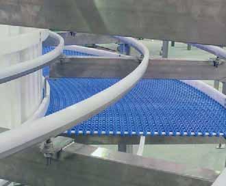
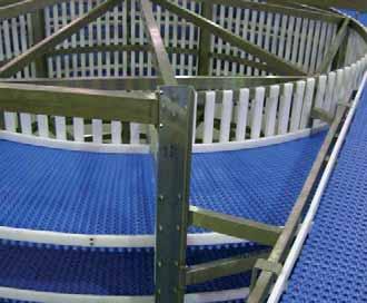
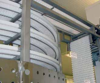
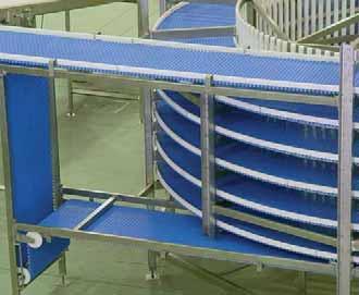
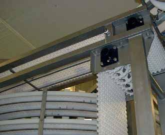
112 111 SERIES 93


113 CATENARIES TAKEUPS TRANSFERENCES WEARSTRIPS INSTRUCTIONS MAINTENANCE CHEMICAL RESISTANCE TECHNICAL DATA
114 TECHNICAL DATA CATENARIES Unlike other conventional conveyor belt systems, in which it is necessary to apply to the belt a high adherence tension with regard to the transmission drums, in the EUROBELT modular conveyor belt system, with direct and positive traction by means of sprockets, this tension must be the minimum necessary, so that the sprockets get correclty fitted to the belt to work properly. To achieve this, it is necessary to leave the belt hanging down freely when coming out of the sprockets, once the first support roller has been surpassed, forming a hanging called catenary curve. It will act as a natural take-up, absorbing the changes in length of the belt owing to expansions and contractions. It will apply a tension fixing the belt on the teeth of the sprockets. Then the belt can rest on return-way rollers, whose distance will be lesser than that of the first catenary, or on wearstrips. CONVEYOR UNDER 2 METRES If the conveyor length is under 2 metres, there will be just one catenary that will hang down freely all along the return way. In this case it will not be necessary to place any roller in the return way. 113
115 TECHNICAL DATA CONVEYOR OVER 2 METRES INFO For conveyor lengths over 2 metres, one return roller will be placed near every shaft, at a distance ranging between 200 and 500 mm, and as many rollers as necessary in the middle, so that the spacing among them range between 850 and 1,200 mm. In the pictures below, we show different examples regarding the arrangement of rollers in the return way to create the catenary curves. Sometimes we can raise the return way of the belt, being reduced the dimensions of the conveyor structure. Series 20 A Nº of teeth T Pitch Ø A B max. C max Series A B C Nº of teeth T Pitch Ø Distance between the sliding surface of the belt and the centre of the shaft. Distance between the vertical of the shaft and the beginning of the sliding surface. Distance between the sliding surface of the belt and the support of the return way. A B max. C max DATA A24 20 INDUSTRY

116 TECHNICAL DATA TAKEUPS As shown in the previous chapter, catenary curves act as dynamic gravity takeups that in many cases can provide enough tension of adherence, so that the sprockets do not slide beneath the belt and can pull it properly. In many cases, these curves do not provide that tension, being necessary the placement of other type of takeups. SCREW TAKE-UP This kind of takeups consists of a a shaft displacement system, normally the idle shaft, that modifies the real belt length and adapt it to the possible changes occurred because of expasions-contractions, losses of tension, etc. To carry out this displacement, the bearing journals are put on some slots in the structure of the conveyor, making the fastening by means of regulating screws. When acting on them, the desired displacement is carried out. Usually these takeups are valid to position the catenary curve, and not as a system to control the changes in the belt length. This type of take-up is suitable to make easy the assembly and dismantling of the belt, as well as to control and regulate the sag of the catenaries. These screw takeups usually will be accompanied usually by other type of complementary take-up, depending on the characteristics of the application. 115
 Weight (kg per m.")
117 TECHNICAL DATA GRAVITY TAKE-UP BY SLIDE GRAVITY TAKE-UP BY SWING ARM PNEUMATIC TAKE-UP These are takeups consisting of a roller with a determined weight that leans on the return way of the belt, supplying enough tension to the sprockets, so that they can perform a proper traction. Series Diameter (mm) Weight (kg per m. of belt width) 20 Ø kg A24 Ø kg 30 Ø kg 40 Ø kg 50 Ø kg 80 Ø kg 93 Ø kg The tension of the belt is managed by displacing the shaft, normally the idle one, through pneumatic cylinders placed at both sides of it. It is ideal for belts subjected to many temperature changes, or for belts that have problems of space to place other type of takeups. DATA A24 20 INFO 116 INDUSTRY


118 TECHNICAL DATA TRANSFERENCES WITH FINGER PLATE The EUROBELT finger plates are used with the Raised Rib type of Series 20, Series A24, Series 30 and Series 41. The transference can be done in the same direction or at 90 degrees, and it is carried out by the own push of the containers among themselves. The transference is performed in a tangential way, both in the belt that delivers the containers and in the belt that receives them, avoiding the stumbling of the product with the edges of transference plates, also called dead plates, as well as the possibility of falls by overturning. It is the ideal transference system for big accumulation tables, palletisers or depalletisers, pasteurisers and intersections of transport lines. Series A B C A WITH DEAD PLATE In applications in which the containers have little stability, the transference area can be covered with a small dead plate made of a material of a low coefficient of friction. It is placed in transferences to be made in the same direction, and it is recommended to be combined with belts of having a small pitch like Series 20, Series A24 or Series 30, and turn diameters as small as possible in order to reduce the length of the dead plate. 117

119 TECHNICAL DATA WITH BELT WITH ROLLERS Using the Series 31 Lateral-Transfer Flat Top, dynamic and smooth lateral transferences can be carried out with no need of finger plates. With one of its edges bevelled we manage to bring nearer the belts taking part in the transference, whereas the lower guides keep the belt aligned. It has been designed for those applications in which we want to avoid the retention of containers in the transference area as well as to achieve more efficiency in their movement. When the containers to be conveyed have a considerable dimension and a good stability, the transference area uses to be covered with free or motorised rollers. This system is suitable both for transferences in the same direction and for those performed at 90 degrees. It can be carried out with any of our belts. DATA A24 20 INFO 118 INDUSTRY

120 TECHNICAL DATA WEARSTRIPS ARRANGEMENT The wearstrips arrangement is an important factor in the life span of a conveyor belt. It should be chosen the most suitable configuration according to the transport needs. To calculate the quantity of supports, the weight of the product to be conveyed should be taken into account. PARALLEL RUNNERS CHEVRON ARRAY It consists of placing the wearstrips in a parallel and continuous way along the conveyor structure. It is preferable to position them so that the joints do not coincide. This is probably the simplest and most economical configuration although, depending on the load to be transported, uneven wears can arise on the back surface of the belt. It is not advisable for applications with a very heavy load. The wearstrips are placed throughout the length and breadth of the conveyor, as shown in the picture above. The possible wear that might occur will be even all over the belt, since it is resting on the wearstrips lengthwise and breadthwise. With this angle-shaped layout the cleaning and the removal of wastes are easy. It is advisable for applications bearing heavy loads or for high speeds. 119


121 TECHNICAL DATA INSTRUCTIONS INFO ASSEMBLY DISMANTLING Eurobelt belts are made of modules which are joined by means of joint rods and which constitute their transport area. Their modular configuration allows us to manufacture a made-to-measure belt for you. We will introduce the rod in the hole existing across every module to join the different lines of modules that make up the belt. The fastening of the rods is carried out by means of extractable caps. These caps will be inserted into the lodgings existing for that purpose in the end modules. Finally, in order to make easier the positioning of the belt on the conveyor, both ends of the belt will be joined at the top of the conveyor. CAP 1- Lean the belt on a smooth area, leaving a free space underneath the line we are going to replace to allow the cap to get out. 2- Now we will pull out the caps placed at both ends, always from the top to the bottom. 3- We will push the rods until releasing the damaged module. 4- We will replace the damaged module and will introduce the rods. 5- Insert the caps, always from the top to the bottom. CLIP 1- Leave a free space underneath the ends of the line to pull out the clips, always from the bottom to the top. 2- Push the rods until releasing the damaged module. 3- Replace the damaged module and introduce the rods. DATA A Insert the clips, always from the top to the bottom. 120 INDUSTRY


122 TECHNICAL DATA MAINTENANCE The maintenance works must be done by qualified personnel and always according to the valid legislation regarding Job Security. Before installing and putting into operation the machine, all the checking and general maintenance instructions given by the manufacturer of the conveyor must be read carefully. It is important to carry out a constant maintenance and/or cleaning of the machine, particularly in those areas in direct contact with the product. First of all the machine will be switched off to avoid the risk of electric shock. Make sure the general switch is in the off position and the emergency stop of the machine is pressed. For cleaning our plastic modular belts use water and gel, and rinse with water and disinfectant. Before applying any gel or disinfectant to the belt, the label of the container should be read carefully to check the composition. In order not to damage the belt, it is essential the composition of the gel and that of the disinfectant to be very low in chlorine. Any cutting element will never be used for the cleaning of the belt as it can cause its deterioration. 121
123 TECHNICAL DATA CHEMICAL RESISTANCE Chemical name Polypropylene Polyethylene Polyacetal 20 ºC 60 ºC 20 ºC 60 ºC 20 ºC 60 ºC Acetic acid V V V Q - - Acetic acid (5%) V V V V V - Acetone V V V V Q Q Alcohol (all types) V V V V - - Aluminium compounds V V V V - - Alums (all types) V V V V - - Ammonia V V V V - - Ammonium compounds V V V V - - Amyl acetate Q NV Q NV - - Amyl chloride NV NV Q NV - - Aniline V V V NV - Q Aqua regia NV NV Q NV - - Arsenic acid V V V V - - Barium compounds V V V V - - Barium soap fat V Q Beer V V V V - - Benzene Q NV Q NV V Q Benzene sulphonic acid (10%) V V V V - - Benzoic acid V V V V - - Borax V V V V - - Boric acid V V V V - - Brake fluid V V - - V V Brine (10%) V V V V V V Bromic acid NV NV NV NV - - Bromine, liquid or vapour NV NV NV NV - - Bromine water NV NV Butyl acetate NV NV Q NV - - Butyl acid NV NV V Q - - Butyric acid V - V Q - - Calcium compounds V V V V - - Calcium soap fat V Q Calgonite (0,3%) V V - - V V Carbon dioxide V V V V - - Carbon disulphide Q NV Q NV - - Carbon tetracloride NV NV NV NV V Q Cellosolve TM V V Chloracetic acid V V Chlorine-gas NV NV Q NV NV NV Chlorine water (0,4% Cl) V Q - - NV NV Chlorobenzene NV NV Q NV - - Chloroform NV NV NV NV - - Chlorosulphonic acid NV NV NV NV - - Chlorox NV V Q - - NV Chromic acid (50%) V V V Q - - Citric acid V V V V - - Citric acid (10%) V V V V V - Citrics juice V V V V - - Clorine liquid NV NV NV NV NV NV Coconut oil V V V V - - Copper compounds V V V V - - Corn oil V V V V - - Cottonseed oil V V V V - - V NV Q Valid Not valid Questionable - No information This chemical resistance guide is merely informative and it is based on specifications given by the suppliers of the technical plastics employed in our manufacturing process. 122 DATA A24 20 INFO INDUSTRY
124 TECHNICAL DATA CHEMICAL RESISTANCE Chemical name Polypropylene Polyethylene Polyacetal 20 ºC 60 ºC 20 ºC 60 ºC 20 ºC 60 ºC Cresol V V V Q - - Cyclohexane V Q NV NV - - Cyclohexanone V Q NV NV - - Detergents V V V V V V Dextrine V V V V - - Di-iso-octyl phthalate V V Dibutyl phthalate V Q Diethanolamine V V - NV - - Diethyl ether NV NV NV NV Q Q Diglycolic acid (30%) V V V V - - Dimethyl phthalate V V Dimethylamine V Dioctyl phthalate V Q Ethyl acetate V V Q Q Q NV Ethyl ether Q Q Ethylamine V V Ethylene chloride NV NV Ethylene glicol (50%) V V V V V Q Ferric/ferrous compounds V V V V - - Formaldehyde (37%) V V V Q - - Formic acid (85%) V Q V V - - Freon - - V V Q Q Fuel oil V Q V NV Q Q Furfural NV NV Q NV - - Glucose V V V V - - Glycerol V V Grease V V V Q - - Heptane NV NV Q NV V V Hexane V Q NV NV - - Hydriodic acid NV NV Hydrobromic acid (50%) V V V V - - Hydrochloric acid V V V V NV NV Hydrochloric acid (10%) V V V V NV NV Hydrofluoric acid (35%) V V V V NV NV Hydrogen peroxide (3%) V V V V V V Hydrogen peroxide (90%) Q Q V Q - - Hydrogen sulphide V V V V - - Igepal (50%) V V - - V Q Iodine-glasses V V Q Q - - Isooctane NV NV V Kerosine Q NV Q Q V V Lactic acid V V V V - - Lanolin V Q V V - - Lard - - V V - - Lauric acid V V V V - - Lead acetate V V V V - - Ligroine Q NV Lime sulfur V Linseed oil V V V V V V Lubricating oil V Q - - V V Magnesium compounds V V V V - - Malic acid (50%) V V V V - - V NV Q Valid Not valid Questionable - No information This chemical resistance guide is merely informative and it is based on specifications given by the suppliers of the technical plastics employed in our manufacturing process. 123
125 TECHNICAL DATA Chemical name Polypropylene Polyethylene Polyacetal 20 ºC 60 ºC 20 ºC 60 ºC 20 ºC 60 ºC Manganese sulphate V - V V - - Margarine V V V V - - Mercury V V V V - - Mercury compounds V V V V - - Methyl cellosolve V Methyl chloride NV NV Methyl ethyl kesone V Q NV NV - - Methyl sulphuric acid V V V V - - Methylene chloride Q NV NV NV - - Mineral oil Q NV V NV V V Mineral alcohols Q NV Molasses V V V V - - Motor oil V Q - - V V Naphtha V Q Q NV - - Nickel compounds V V V V - - Nitric acid (30%) V Q V V NV NV Nitric acid (50%) Q NV V Q NV NV Nitric acid (fuming) NV NV NV NV NV NV Nitrobenzene V Q NV NV - - Nitrous acids Q NV Nitrous oxide V Oil for transformers V Q V Q - - Oleic acid V NV - - V V Olive oil V V V V - - Oxalic acid V V V V - - Oxygen NV NV Ozone NV NV Q NV - - Palmitic acid (70%) V V V V - - Perchloric acid (20%) V V V V - - Perchloroethylene NV NV NV NV - - Petrol Q NV V NV V V Phenol (5%) V V V V NV NV Phenol V V V V NV NV Phosphoric acid (30%) V V V V - - Phosphoric acid (85%) V V V V - - Photographic solutions V V V V - - Phthalic acid (50%) V V V V - - Plating solutions V V V V - - Potassium compounds V V V V - - Potassium iodide 3% iodine V V V V - - Potassium hydroxide V V V V - - Potassium permanganate V Q V V - - Silver cyanide V V Silver nitrate V V V V - - Sodium chlorite V Q V V - - Sodium compounds V V V V - - Sodium hydroxide V V V V - - Sodium hydroxide (60%) V V V V V V Sodium hypochlorite (5% Cl.) V Q - - NV NV Stannic chloride V V V V - - Stannous chloride V V V V - - Stearic acid V Q V V - - V NV Q Valid Not valid Questionable - No information This chemical resistance guide is merely informative and it is based on specifications given by the suppliers of the technical plastics employed in our manufacturing process. 124 DATA A24 20 INFO INDUSTRY
126 TECHNICAL DATA CHEMICAL RESISTANCE Chemical name Polypropylene Polyethylene Polyacetal 20 ºC 60 ºC 20 ºC 60 ºC 20 ºC 60 ºC Succinic acid V V V V - - Sugar V V V V - - Sulphamic acid (20%) V V - - NV NV Sulphite solutions V V Sulphur V V V V - - Sulphur bioxide V V V V - - Sulphur chloride V Sulphuric acid (3%) V V V V V V Sulphuric acid (50%) V V V V NV NV Sulphuric acid (70%) V Q V Q NV NV Sulphuric acid (fumming) NV NV NV NV NV NV Sulphurous acid V - V V - - Tannic acid (10%) V V V V - - Tartaric acid V V V V - - Tetrahydrofurane Q NV Toluene NV NV NV NV Q NV Tomato juice V V V V - - Tributylic phosphate V Q Trichloroacetic acid V V Trichloroethylene NV NV NV NV - - Tricresylic phosphate V Q Trisodium phosphate V V V V - - Turbosine Q NV Q Q V V Turpentine Q NV Q NV - - Urea V V V V - - Vinegar V V V V - - Wine V V V V - - Xylene NV NV NV NV - - Zinc compounds V V V V - - V NV Q Valid Not valid Questionable - No information This chemical resistance guide is merely informative and it is based on specifications given by the suppliers of the technical plastics employed in our manufacturing process. 125


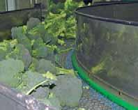
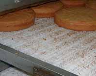
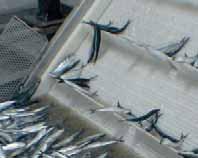
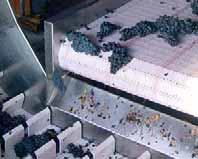
127 CAR POULTRY BEVERAGE MEAT VEGETABLES CONFECTIONERY FISH WINE INDUSTRY


128 INDUSTRY CAR Applications 20 A Charge of batteries All kind of curves Degreasing Elevating lines Elevators of residues FT FT FT FT Tyre production lines FT FT Positioning for welding FT FT Bidirectional conveyors Transport of people NS KN CF Transport of delicate pieces FT FT Transport of cars NS KN CF FT PF RR OG KN CO TR NS FR CF SR LT Flat Top Perforated Flat Top Flush Grid Raised Rib Open Grid Knurled Conic Trian Non Slip Friction Top Conic Friction Sliding Rollers Lateral Transfer 127


129 INDUSTRY POULTRY INFO Applications 20 A Accumulation of containers FT FT Boiling All kind of curves Metal detectors FT Chicken frames elevation FT FT Elevating and descending spirals Washers of containers Quartering lines Packaging lines Reject by weight control Non-slip conveyors FT PF RR OG KN CO TR NS FR CF SR LT Flat Top Perforated Flat Top Flush Grid Raised Rib Open Grid Knurled Conic Trian Non Slip Friction Top Conic Friction Sliding Rollers Lateral Transfer FT FR FT FT FT FT FT FT FR CF FT CF DATA A INDUSTRY


130 INDUSTRY BEVERAGE Applications 20 A All kind of curves Casing FT - RR FT - RR FT - RR Coolers RR RR Elevating and descending spirals Filters of residues PF- OG PF Control and inspection FT - RR Washers High speed lines FT LT FT Palletisers and depalletisers FT - RR FT - RR FT - RR Pasteurisers RR Accumulation tables FT - RR FT - RR FT - RR FT PF RR OG KN CO TR NS FR CF SR LT Flat Top Perforated Flat Top Flush Grid Raised Rib Open Grid Knurled Conic Trian Non Slip Friction Top Conic Friction Sliding Rollers Lateral Transfer 129


131 INDUSTRY MEAT INFO Applications 20 A Boiling FT PF Metal detectors FT Elevators FT FT FT FT FT Washers Cut and quartering lines Evisceration lines Transport and inspection lines FT FT FT Liquid injection machines Plastic film wrapping FT Vacuum machines Freezing tunnels Pasteurisers FT PF RR OG KN CO TR NS FR CF SR LT Flat Top Perforated Flat Top Flush Grid Raised Rib Open Grid Knurled Conic Trian Non Slip Friction Top Conic Friction Sliding Rollers Lateral Transfer FT FT FT OG OG OG FT PF FT FT PF FT DATA A INDUSTRY


132 INDUSTRY VEGETABLES Applications 20 A Boiling FT - PF FT PF Freezers All kind of curves Metal detectors FT FT FT FT Swan-necked elevators FT FT FT Casing RR RR RR RR Sewage filter RR RR RR OG Hydrocooling Transport lines in flooded pools FT PF FT PF Selection tables in closed circuit Pasteurisers RR Non-slip conveyors FR KN FR CF Treatment with acids OG FT PF RR OG KN CO TR NS FR CF SR LT Flat Top Perforated Flat Top Flush Grid Raised Rib Open Grid Knurled Conic Trian Non Slip Friction Top Conic Friction Sliding Rollers Lateral Transfer 131


133 INDUSTRY CONFECTIONERY INFO Applications 20 A Accumulation tables of boxes and containers SR FT - SR SR SR Loaders of tunnel ovens All kind of curves Metal detectors Elevators with flights Vertical elevators Cooling and freezing spirals Cooling lines FT RR Selection tables FT FT RR Accumulation tables RR RR RR Non-slip conveyors FT PF RR OG KN CO TR NS FR CF SR LT Flat Top Perforated Flat Top Flush Grid Raised Rib Open Grid Knurled Conic Trian Non Slip Friction Top Conic Friction Sliding Rollers Lateral Transfer FR FT FT FT FT KN - FR CF FT FT CF CO DATA A24 20 INDUSTRY 132


134 INDUSTRY FISH Applications 20 A Boiling Desfreezing TR OG Metal detectors FT FT FT FT FT Elevators FT FT FT FT FT Icing of frozen products -RR TR RR RR OG Washers Aseptic transport lines FT FT FT Plastic film wrapping FT - RR FT - RR FT - RR FT Macerating and mixing applications PF PF PF Brine treatment TR OG Freezing tunnels TR OG Drying tunnels FT PF RR OG KN CO TR NS FR CF SR LT Flat Top Perforated Flat Top Flush Grid Raised Rib Open Grid Knurled Conic Trian Non Slip Friction Top Conic Friction Sliding Rollers Lateral Transfer 133


135 INDUSTRY WINE INFO Applications 20 A Infeed for stalk removing FT Bottles feeding FT FT Elimination belts Casing Elevators Washers RR Lines of different speeds FT FT Selection tables Palletisers and depalletisers Pasteurisers Accumulation tables Reception hoppers FT PF RR OG KN CO TR NS FR CF SR LT Flat Top Perforated Flat Top Flush Grid Raised Rib Open Grid Knurled Conic Trian Non Slip Friction Top Conic Friction Sliding Rollers Lateral Transfer FT RR RR FT RR RR RR FT RR LT FT RR RR RR RR FT FT FT FT DATA A INDUSTRY
136 CUSTOMER SERVICE NECESSARY INFORMATION FOR THE CHOICE OF THE SUITABLE BELT 1- Total length between conveyor centres (mm). 2- Usable belt width (mm). 3- Conveying speed (m/min). 4- Weight of the product (kg/m²). 5- Max. work temperature (ºC). 6- Type, material and dimensions of the product to convey 7- Dry or wet use of the belt. 8- In case of accumulation, advise the percentage (%). 9- The conveyor works in one or two senses. 10- Central drive? 11- Horizontal or inclined conveyor. 12- If it is an inclined conveyor, difference between heights. 13- Is there an abrasive atmosphere? 14- Is there any impact? If so, describe it. 15- Upon which material does the belt slide? 16- If plastic belt is used, mark and reference. NOTES 135
137 CUSTOMER SERVICE ENQUIRY FORM SERIES 20 A TYPE MATERIAL OF THE BELT MATERIAL OF THE RODS FLAT TOP NON SLIP POLYPROPYLENE POLYPROPYLENE PERFORATED FT KNURLED POLYETHYLENE POLYETHYLENE FLUSH GRID CONIC POLYACETAL POLYACETAL OPEN GRID FRICTION TOP CONDUCTIVE POLYPROPYLENE NYLON RAISED RIB CONIC FRICTION CONDUCTIVE POLYACETAL STAINLESS STEEL LATERAL TRANSFER SLIDING ROLLERS TRIAN COLOUR OF THE BELT WHITE GREY NATURAL BLUE BLACK FLGHTS SIDE GUARDS STREAMLINE - NO CLING BENT RIBBED (S-50) 50 mm 25 mm 25 mm 75 mm 75 mm INDENT 50 mm 50 mm 100 mm Nº LINES 75 mm 75 mm 100 mm 100 mm INDENT HOLD-DOWN ROLLERS 125 mm 150 mm BELT WIDTH 125 mm 150 mm PITCH CENTRAL DRIVE SERIES 40 SERIES 50 SERIES 80 INDENT PITCH Nº LINES BELT LENGTH YES NO ACCESSORIES SPROCKETS FINGER PLATES HOLD-DOWN PROFILES SERIES MATERIAL SERIES 20 GEOMETRY TEETH POLYPROPYLENE SERIES A24 / 30 / 41 IN L 35 X 12 BORE POLYACETAL STAINLESS STEEL MATERIAL NYLON IN L 40 X 20 IN U 20 X 14 QUANTITY POLYACETAL IN U 20 X 30 RETAINING RINGS QUANTITY QUANTITY WEARSTRIPS POLYACETAL POLYETHYLENE CONDUCTIVE POLYETHYLENE QUANTITY NOTES TO BE SHIPPED TO: CONTACT: ADDRESS: PHONE.: FAX.: PLEASE, INDICATE IF YOU ARE: OEM END-USER 136


138 CUSTOMER SERVICE CUSTOMER SERVICE EUROBELT elements are manufactured with plastic materials. Consequently, their direct exposure to fire or to higher temperatures than those indicated can produce their deflagration together with the emission of toxic fumes. EUROBELT elements are guaranteed for a period of one year from the date of shipment with respect to the repair or substitution of any component whose materials or manufacture is defective, provided it is demonstrated that the work has been done under normal conditions of use. No other expressed or implicit guarantee is given, unless it were set down in writing and approved by the manufacturer. Any use of the EUROBELT products has to observe the regulations and rules prevailing and the user is the only responsible to make observe these regulations when incorporating those products into any machine. To clean our plastic modular belts, use water and gel, rinse with water and disinfectant. We recommend the manipulation to be always carried out by qualified personnel as well as to fulfil the instructions of revision and maintenance given by the manufacturer of the conveyor. The data included here are of informative nature. Their applicability to the design of any installation is not guaranteed. The manufacturer does not assume any responsibility for the repercussions derived from the use of his products, whether it is based or not on the information herein. DISTRIBUTOR AFHER EUROBELT S.A. Topacio, Valladolid SPAIN Tel.: Fax.: afher@eurobelt.com A Depósito Legal: VA- 137


139 SERIES CONVEYOR BELTS SERIES C12 FLUSH GRID FLUSH GRID Bidirectional, with a 12 mm pitch, it is ideal for small product transfers at high speed. high speed conveying very small product transfer metal detectors container handling With a 12 mm pitch you will be able to carry out product transfers at high speed in minimum turn diameters. Its open-and-closed link structure, shaping a kind of knot, provides a great load capacity. Its design with the rod in view and its extraordinary open surface implies a great easiness for cleaning. AFHER EUROBELT S.A. Topacio, Valladolid Spain Phone: Fax: afher@eurobelt.com web:

140 9 CONVEYOR BELTS SERIES C12 SERIES C12 FLUSH GRID 12 Bidirectional, with a 12 mm pitch, it is ideal for small product transfers at high speed. It is manufactured in polypropylene, polyethylene and polyacetal obseing the International Regulations to be used in food processes. Pitch Surface 12 mm Flush Grid Open area 26 % Thickness Drive system Belt width Advised minimum width 9 mm Hinge Multiples of 25 mm 150 mm Rod diameter Ø 4.6 mm Retention system Cap Belt strength Temperature Belt weight Available the belt the rod (kg/m) range (ºC) (kg/m 2 ) colours in stock PP - Polypropylene PP - Polypropylene to [W] - [G] PE - Polyethylene PE - Polyethylene to [N] AC - Polyacetal PP - Polypropylene 1, to [N] - [B] AC - Polyacetal PE - Polyethylene 1, to [N] - [B] Colours: [W] White - [G] Grey - [B] Blue - [N] Natural
![SERIES C12 CONVEYOR BELTS ACCESSORIES SPROCKET[SPROCKETS] Square bore 25 Nº of teeth T Ø Pitch Bore for square shaft mm inch Hub width A B max. C 11 42.59 20 3/4 25 16 22 41 20 76.](/docs-images/94/118246564/images/141-0.jpg "7 40 1-1/2 25 34 35 77 26 99.55 40 1-1/2 25 45 40 99 31 118.61 40 60 1-1/2 2-1/2 25 55 45 119 40 152.")
 by 75 mm. This amount must always be odd.")
141 SERIES C12 CONVEYOR BELTS ACCESSORIES SPROCKET[SPROCKETS] Square bore 25 Nº of teeth T Ø Pitch Bore for square shaft mm inch Hub width A B max. C / / / /2 2-1/ /2 2-1/ EUROBELT offers all sprockets in polypropylene, polyacetal and in stainless steel for those applications in which it is required. To calculate the minimum quantity of sprockets required both in the drive shaft and in the idle one, you should divide the belt width (in mm) by 75 mm. This amount must always be odd. We have plastic sprockets for round shaft with and without keyway. B B A C A B C Distance between the sliding surface of the belt and the centre of the shaft. Distance between the vertical of the shaft centre and the beginning of the sliding surface. Recommended distance between the sliding surface of the belt and supports of the return way.


142 R9 SERIES C Ø 75 Min. 40º - 50º Ø 75 Min. 75 In every installation there are the so-called dead areas among the different machines and conveyors through which the product must go without any productivity loss. In EUROBELT we have developed this plastic modular belt, launched as Series C12, with which the dead areas have been reduced up to 20 mm DISTRIBUTOR: AFHER EUROBELT S.A. Topacio, Valladolid (Spain) Phone: Fax: afher@eurobelt.com web: [D1-2010]


143 SERIES CONVEYOR BELTS SERIES E30 OPEN GRID OPEN GRID Open surface with mini-flights, it is perfect for fish and seafood industry. glazing elevation cooling boiling Special for product-in-bulk processes in inclined planes when the use of conventional flights is not possible. It makes easier the transference, reduces the unevenness of unloading, and avoids the loss of product in the belt return. These mini-flights reduce the contact surface between product and belt, decreasing the adherence in processes like fish glazing and transport of frozen fish. unfreezing AFHER EUROBELT S.A. Topacio, Valladolid Spain Phone: Fax: web:


144 5 SERIES E30 OPEN GRID Their mini-flights help product in bulk to elevate and descend. The great open area allows an excellent liquid drainage and an easy cleaning during maintenance operations. It is manufactured in polypropylene, polyethylene and polyacetal. These materials observe the International Regulations for their use in food processes. The minimum spacing between the transversal edges is 30 mm and it can be increased in multiples of 30 mm. BELT DATA Pitch 30 mm Open area 41% the belt Polypropylene Polyethylene Polyacetal Belt width Multiples of 10 mm Spacing between edges Multiples of 30 mm DISTRIBUTOR: AFHER EUROBELT S.A. Topacio, Valladolid (Spain) Phone: Fax: afher@eurobelt.com web: [C1-2008] Depósito Legal: VA


145 SERIES CONVEYOR BELTS FRICTION TOP BELTS Designed for providing an excellent adherence between product and belt to solve transport problems in inclined planes. FLAT FRICTION TOP cartons bags shrink-wrappings tyres baggage trays TRIAN FRICTION TOP metallic plates containers glass Friction Top surfaces succeed in combining plastic and rubber in one only piece taking advantage both of the modular system and of the adherence. Both surfaces are manufactured in three Shore grades: A45, A55 and A64, covering a wide range between two different features, adherence and wear. AFHER EUROBELT S.A. Topacio, Valladolid Spain Phone: Fax: afher@eurobelt.com web:
146 FRICTION TOP BELTS FLAT FRICTION TOP TRIAN FRICTION TOP Flat Friction Top, with a flat rubber surface, is perfect for applications in which a maximum adherence is needed. Trian Friction Top, designed with small transversal triangles, like mini flights, enables as well an easy and efficient cleaning Rubber Rubber Plastic Plastic BELT DATA Plastic colour Rubber colour Belt strength Temperature range Approved by the FDA Rubber hardness grades Shore A45 Shore A55 Shore A64 Grey White Grey Black Beige Beige 1,100 kg/m 1,100 kg/m 1,100 kg/m +1 to ºC +1 to ºC +1 to ºC no yes yes Material: Polypropylene Polyethylene Belt width: Multiples of 10 mm Spacing of rubber lines: It can be assembled with all lines in rubber or spacing them in multiples of 30 mm DISTRIBUTOR: AFHER EUROBELT S.A. Topacio, Valladolid (Spain) Phone: Fax: afher@eurobelt.com web: [C1-2008] Depósito Legal: VA


147 SERIES CONVEYOR BELTS SERIES B50 FLAT TOP FLAT TOP The strongest and most hygienic plastic modular belt for the food industry. Design of completely rounded corners and open edges in order to avoid the accumulation of dirt in any place. Bigger opening in the hinge area. Down time for cleaning gets reduced. The underside transversal drive bar and the sprockets design make this belt be the best alternative for longer conveyors with heavier loads. Greater resistance to wear in operations with cutting tools and to impact of heavy products. Manufactured with materials that comply the International Regulations regarding the direct contact with food. the belt Polypropylene Polyethylene Polyacetal the rod Polypropylene Polyethylene Polypropylene Belt strength (kg/m) 1, ,650 Temperature range ºC +1 to +104 ºC -50 to +65 ºC +1 to +90 ºC Belt weight (kg/m 2 ) AFHER EUROBELT S.A. Topacio, Valladolid Spain Phone: Fax: afher@eurobelt.com web:
 Bore (inch) Hub width A B max. C max. 8 130.65 40 1.5 40 58 60 135 10 161.")


148 SERIES B50 FLAT TOP - ACCESSORIES SPROCKETS Eurobelt offers all sprockets in polypropylene and polyacetal. Ask for round bore availability. Maximum spacing between sprockets: 150 mm. Bore Hub width Sprockets Teeth T Pitch Ø Bore (mm) Bore (inch) Hub width A B max. C max / / / / /60/ /2.5 / B B A C max A: Distance between the sliding surface of the belt and the centre of the shaft. B: Distance between the vertical of the shaft and the beginning of the sliding surface. C: Distance between the sliding surface of the belt and the support of the return way. Flights FLIGHTS AND SIDE GUARDS / 90 / / 75 / STREAMLINE - NO CLING BENT SIDE GUARDS Flights and side guards DISTRIBUTOR: AFHER EUROBELT S.A. Topacio, Valladolid (Spain) Phone: Fax: afher@eurobelt.com web: [C1-2008] Depósito Legal: VA


149 SERIES CONVEYOR BELTS NO CLING FLIGHTS Accessory to solve problems in incline curved conveyors. curve These flights give response to problems arising in elevating, descending and accompaniment applications, preventing the product from sliding on the belt. They can be used both in right and in curve sections. They are available in heights of 25 and 50 mm in the following materials: polypropylene, polyethylene and polyacetal. AFHER EUROBELT S.A. Topacio, Valladolid Spain Phone: Fax: web:


150 SERIES E93 FLIGHT The E93 curve Series has no cling fights as an accessory for building elevating conveyors. Every flight is 25 or 50 mm high with regard to the belt surface and they can be used both in right and curve sections. Its non-stick side has ribs that project over the surface to prevent the product from sticking. Their edges are completely rounded to avoid any damage of the product. CONSTRUCTION OF BELT WITH FLIGHTS Multiples of 60 mm Material Polypropylene Polyethylene Polyacetal INDENT 25 / 50 Drive direction Indent 38 mm 63 mm 88 mm Belt width Multiples of 25 mm Distance between flights Multiples of 60 mm DISTRIBUTOR: AFHER EUROBELT S.A. Topacio, Valladolid (Spain) Phone: Fax: afher@eurobelt.com web: [C1-2008] Depósito Legal: VA
Advised minimum width SLIDING ROLLERS SERIES 20
 Pitch Drive system Belt width Advised minimum width Rod diameter 20 mm Central Multiples of 8 mm 120 mm Ø 4.6 mm FLAT TOP FLUSH GRID RAISED RIB FRICTION TOP SLIDING ROLLERS TRIAN SERIES 20 SERIES 20 SERIES
MATERIAL HANDLING SYSTEMS
 MATERIAL HANDLING SYSTEMS Transport Systems MODULAR BELTS We specialized in custom design and development of high performance plastic components for material handling systems. SERIES PLA_00 SERIES PLA_030
COMPANY PROFILE. ...dedication to constant skills improvement, keeping up to date with the latest technical developments and passion for innovation...
 COMPANY PROFILE Welcome to our Bluebelt profile page, and thank you for taking the time to read about us. Our company was founded in 1999 by Christopher Dale, and over the past 12 years has become a leading
1000-SERIES MODULAR BELTS
 1000-SERIES MODULAR BELTS The 1000-series belt is multifunctional. The pitch is 1 inch. BENEFITS Perfect product handling 1000-Series belts have a relatively small 1 pitch, the material has a very low
POSITIVELY DRIVEN CONVEYOR BELTS
 CONVEYOR BELTS www.mafdel-belts.com www.food-conveyor-belts.com GB CONFIGURATION HORIZONTAL CONVEYOR BIDIRECTIONAL CONVEYOR FLIGHTED AND SIDEWALL CONVEYOR TROUGHED CONVEYOR 3 ADVANTAGES Our positive drive
POSITIVELY DRIVEN CONVEYOR BELTS
 CONVEYOR BELTS www.mafdel-belts.com www.food-conveyor-belts.com GB CONFIGURATION HORIZONTAL CONVEYOR BIDIRECTIONAL CONVEYOR FLIGHTED AND SIDEWALL CONVEYOR TROUGHED CONVEYOR 3 ADVANTAGES Our positive drive
Main features: All the Megablue product line is FDA/USDA/USDA Dairy Approved.
 MEGABLUE Megablue Megablue is Megadyne s product, specifically created to give a good alternative to the classical plastic modular belt for the food processing industry. This product, with its smooth surface,
ROUND LINK CHAIN DRIVE SYSTEM
 524 0508 274 366 customerservices@bridoncookes.co.nz Round Link Chain Drive Systems.... 526 Introduction.... 526 Solutions to Old Problems.... 527 Applications.... 528 Tecdos Omega Drive.... 529 Pocket
Conveyor chain catalogue
 Conveyor chain catalogue www.renold.com Table of Contents Section - Conveyor Products and Dimensions Conveyor chain introduction....................................................................5-7 BS
KNIFE GATE VALVES -- MODEL D
 PRODUCT DESCRIPTION Flanged unidirectional knife gate valve for high pressure applications One piece integral cast body with seating wedges and bolted bonnet. High flow rates with low pressure drops. Several
6990 Series Hybrid MatTop Chain Product Brochure. Rexnord 6990 Series Hybrid MatTop Chain
 6990 Series Hybrid MatTop Chain Product Brochure Rexnord 6990 Series Hybrid MatTop Chain Breakthrough Automotive Solution Count on Rexnord 6990 Series Hybrid MatTop Chain to support you in your automotive
From a modest beginning in 1976 producing small. quantities of gravity conveyor rollers, Arnott Handling
 ARNOTT HANDLING LTD From a modest beginning in 1976 producing small quantities of gravity conveyor rollers, Arnott Handling Equipment Limited has grown to become one of the United Kingdom s foremost manufacturers
Rexnord 6990 Series Hybrid MatTop Chain Product Brochure. Rexnord 6990 Series Hybrid MatTop Chain
 Rexnord 6990 Series Hybrid MatTop Chain Product Brochure Rexnord 6990 Series Hybrid MatTop Chain Automotive Solution Breakthrough 6990 Series H4 Hybrid MatTop Chain Rexnord 6990 Series Hybrid H4 MatTop
6990 Series Hybrid MatTop Chain Product Brochure. Rexnord 6990 Series Hybrid MatTop Chain
 6990 Series Hybrid MatTop Chain Product Brochure Rexnord 6990 Series Hybrid MatTop Chain Breakthrough Automotive Solution Count on Rexnord 6990 Series Hybrid MatTop Chain to support you in your automotive
ASHWORTH ENGINEERING Committed to on-time delivery of defect-free products and services, fit for use, exactly as promised, every time.
 ASHWORTH ENGINEERING Committed to on-time delivery of defect-free products and services, fit for use, exactly as promised, every time. PRODUCT TECHNICAL BULLETIN Reduced Radius Omni-Pro 100 USA and International
KNIFE GATE VALVES -- MODEL A
 PRODUCT DESCRIPTION Wafer style, uni-directional knife gate valve. One piece integral cast body with guides to support the gate and seating wedges. High flow rates with low pressure drops. Several seat
PLASTICS INDEX...L-1 PLASTIC CAPABILITIES...L-2
 Index SECTION L PRODUCT PAGE INDEX...L-1 PLASTIC CAPABILITIES...L-2 SECTION I NON-METALLIC SPROCKETS...L-3 - L-12 Sprockets - Stock No. 25 1/4" Pitch...L-3 No. 35 3/8" Pitch...L-4 No. 40 1/2" Pitch...L-5
Design Innovative, robust construction, straight section eliminated before and after curve. Features Speed: Up to 70 meters per minute
 The new modular radius belt is available in different widths with a closed-top surface capable of handling a variety of package sizes, types and configurations including delicate products and applications
Download the most up-to-date version at KleanTop Belt Product Catalog
 Download the most up-to-date version at www.rexnord.com/documentation KleanTop Belt Product Catalog Conveniently Accessible Online Information We realize the success of your business depends on up-to-date
Conveyors 12. slide strips roller Conveyors roller elements Conveyor rollers Chain Transfer
 Conveyors slide strips roller Conveyors roller elements Conveyor rollers Chain Transfer Application example conveyors Transport solutions and goods provision 1 2 3 4 5 6 7 8 362 9 1 slide strips Low-wear
Omni-Pro 075. USA and International Patents Pending
 ASHWORTH ENGINEERING Committed to on-time delivery of defect-free products and services, fit for use, exactly as promised, every time. P R O D U C T T E C H N I C A L B U L L E T I N Omni-Pro 075 USA and
SKF Flex Coupling Installation Instructions
 SKF Flex Coupling Installation Instructions The performance of the coupling depends largely upon how you install and maintain. 1. Thoroughly clean all components, paying particular attention to the removal
P R O D U C T T E C H N I C A L B U L L E T I N
 ASHWORTH ENGINEERING Committed to on-time delivery of defect-free products and services, fit for use, exactly as promised, every time. P R O D U C T T E C H N I C A L B U L L E T I N OMNI-FLEX 3 X 1 FLAT
Series SK Straight running plastic chains
 Series 80-83 - SK 38-8 - 857 Straight running plastic chains 80 STRAIGHT RUI CHAIS RD=50 38. 38. 7..5 3.5 9.5 Ø 6.35. STRAIGHT RUI CHAIS Series 80 Applications: Food and beverage industry: Conveying lines
DynaCon Instruction Manual
 DynaCon Instruction Manual Table of Contents Technical Specification & Warranty.... 3 Construction, Benefits & Safe Operating Procedures... 4 Noise Levels... 5 Installation, Operation & Maintenance...
Index. Purchase guide. Belt conveyor. Elevator Belt conveyor. Modular belt conveyor. Stainless steel belt & slat chain conveyor. Accessories & options
 belts SOMEFI is a company dedicated to the manufacture and sale of conveyors and modular handling equipment. For more than 40 years SOMEFI has offered a complete range of industrial conveyors, of flexible
Apron Feeders. TEREX JAQUES APRON FEEDERS Capacities up to 14,500 tph Proven design based on crawler tractor components Custom designed for the duty
 Apron Feeders TEREX JAQUES APRON FEEDERS Capacities up to 14,500 tph Proven design based on crawler tractor components Custom designed for the duty Apron Feeders Terex Jaques Apron Feeders use heavy-duty
INSTALLATION, OPERATION & MAINTENANCE MANUAL Description Handling Installation Actuators...
 INSTALLATION, OPERATION & MAINTENANCE MANUAL INDEX Page 0 - Description 2 1 - Handling 2 2 - Installation 2 3 - Actuators 5 4 - Maintenance 5 41 - Gland packing replacement 6 42 - Seal replacement 6 43
BI-ECCENTRIC Disc Retention Valve
 05/11/2015 - Oscillating disc retention valve with dual eccentricity and straight seat. - Option of manufacturing WAFER type or with flange boring in accordance with customer requirements. - Distance between
CONVEYOR COMPONENTS CONVEYORS. All Belts are available in a variety of pitches and materials. FREEFAX:
 Freephone lines are open between 8.00am and 5.pm 0800 80 CONVEYOR COMPONENTS Moody have been appointed as a unichain distributor, and are able to offer the full range of unichain products. Chains are available
ASHWORTH ENGINEERING Committed to on-time delivery of defect-free products and services, fit for use, exactly as promised, every time.
 ASHWORTH ENGINEERING Committed to on-time delivery of defect-free products and services, fit for use, exactly as promised, every time. PRODUCT TECHNICAL BULLETIN OMNI-GRID & OMNI-LITE Turn Curve belting
LUBRICANTS CHAIN OILS YOUR ADVANTAGE IN AN INDUSTRIAL WORLD
 LUBRICANTS CHAIN OILS YOUR ADVANTAGE IN AN INDUSTRIAL WORLD THE EXPERTS IN CHAIN OIL TECHNOLOGY CASTROL OFFERS YOU A COMPLETE RANGE OF WORLD-CLASS CHAIN LUBRICANTS AND PRODUCT SUPPORT SERVICES DESIGNED
Index SECTION L PLASTICS
 Index SECTION L PLASTICS PRODUCT PAGE SECTION I NON-METALLIC SPROCKETS.... L-2 L-30 SPROCKETS - STOCK NO. 25 ¼" PITCH...L-5 NO. 35 3 8" PITCH...L-6 NO. 40 ½" PITCH...L-7 NO. 50 5 8" PITCH...L-8 NO. 60
SSV TM100 - SSV TM215 DRUM MOTORS 4.0" to 8.5" diameter 0.11 to 7.5 hp SANITARY DRUM MOTORS
 Engineered to Keep Your Business Running SSV TM100 - SSV TM215 DRUM MOTORS 4.0" to 8.5" diameter 0.11 to 7.5 hp SANITARY DRUM MOTORS BELT PULL (BP) = (F0 + F1 + F2) Roller Bed Conveyor Slider Bed Conveyor
Marine Engineering Exam Resource Review of Couplings
 1. What are rigid couplings used for? Used to join drive shafts together. True alignment and rigidity are required. Example Drive shafts and production lines, bridge cranes, solid shaft that needs to be
Visual index NEW PRODUCTS NEWS NEWS PHARMA PHARMA PHARMA. To be continued on next page
 NEWS 3 2013 Visual index Stainless Stainless 2012 NEW PRODUCTS Stainless NEWS Pin with weldable fastening button Stainless Panel fastening p.n1 button Stainless p.n2 Aluminium hinge external fastening
TECDOS Omega Drive. TOUGH DRIVE for any environment. For horizontal, vertical and rotational drive applications. Problems you may have encountered
 TECDOS Omega Drive TOUGH DRIVE for any environment For horizontal, vertical and rotational drive applications Advantage Round steel chain Advantage Minimum wear 2 Problems you may have encountered Disadvantages
Products Media No HabasitLINK Plastic Modular Belts Product Overview. Habasit Solutions in motion
 Products Media No. 4128 HabasitLINK Plastic Modular Belts Product Overview Habasit Solutions in motion Contents 2 Product features 3 Product overview 4 Accessories 11 Features and benefits 12 Services
Profi le rail guides LLR
 Profi le rail guides LLR Content The SKF brand now stands for more than ever before, and means more to you as a valued customer. While SKF maintains its leadership as the hallmark of quality bearings throughout
Factor 1 Sensors: Proximity sensors that detect all metals at the same range without adjustment.
 Factor 1 Sensors: Proximity sensors that detect all metals at the same range without adjustment. A White Paper TURCK Inc. 3000 Campus Drive Minneapolis, MN 55441 Phone: (763) 553-7300 Fax: (763) 553-0708
uni Flex SNB Sideflexing
 uni Flex S 132 Pitch 25.4 (1.00 ) uni Flex S strong and tight radius sideflexing belt uni Flex S 1 pitch is created to optimize throughput in high volume operations with space limitations. The belt has
CONVEYING BELTS FOR AUTOMOTIVE THE SUSTAINABLE COMPONENT FOR THE TRANSPORT IN THE VEHICLE ASSEMBLY
 CONVEYING BELTS FOR AUTOMOTIVE THE SUSTAINABLE COMPONENT FOR THE TRANSPORT IN THE VEHICLE ASSEMBLY WE THE TEAM OF STRICKER STAND FOR: professional consultation CONFIDENT CONVEYING ECONOMICAL CONSUMPTION
Food Processing Conveyor Guidelines
 Food Processing Conveyor Guidelines Revision 3: 2017 TABLE OF CONTENTS Belt Installation Plastic Link Style. 10 Belt Installation ThermoDrive... 8 Belt Removal Plastic Link Style.. 10 Belt Removal ThermoDrive.
ROLL-UP COVERS Special Products
 SURE-SPRING (Patented) The P.E.I. Patented design known as SURE-SPRING represent the most advanced level of technical innovation in the field of roll-up covers. The spring mechanism design takes into account
Moments. It doesn t fall because of the presence of a counter balance weight on the right-hand side. The boom is therefore balanced.
 Moments The crane in the image below looks unstable, as though it should topple over. There appears to be too much of the boom on the left-hand side of the tower. It doesn t fall because of the presence
P R O D U C T T E C H N I C A L B U L L E T I N
 ASHWORTH ENGINEERING Committed to on-time delivery of defect-free products and services, fit for use, exactly as promised, every time. P R O D U C T T E C H N I C A L B U L L E T I N USA and International
For advanced drive technology CLAMPEX. Shaft-hub-connection. KTR Precision joints CLAMPEX
 technology CLAMPEX Shaft-hub-connection CLAMPEX KTR Precision joints 227 technology Table of contents Page Brief information 228 Selection and calculation 25-255 CLAMPEX -Selection Shaft diameter = d 0
FlatTop 7956 MatTop Chains Brochure. Rexnord 7956 Side-Flex MatTop Chains
 FlatTop 7956 MatTop Chains Brochure Rexnord 7956 Side-Flex MatTop Chains Rexnord 7956 Side-Flex MatTop Chains. Strong in Curves. Durable and Efficient. Rexnord is pleased to announce the introduction of
Shaft-Hub-Connections
 Stand: 14.01.2010 Shaft-Hub-Connections Shrink Discs Cone Clamping Elements Star Discs 36 Edition 2012/2013 RINGSPANN Eingetragenes Warenzeichen der RINGSPANN GmbH, Bad Homburg Table of Contents Introduction
Omni-Pro 120. USA and International Patents Pending
 ASHWORTH ENGINEERING Committed to on-time delivery of defect-free products and services, fit for use, exactly as promised, every time. P R O D U C T T E C H N I C A L B U L L E T I N Omni-Pro 120 USA and
For advanced drive technology CLAMPEX. Shaft-Hub-Connection. KTR Precision Joints CLAMPEX
 technology CLAMPEX Shaft-Hub-Connection CLAMPEX KTR Precision Joints 07 technology Table of contents Page Brief information 09 Selection and calculation -5 CLAMPEX -Selection Shaft diameter = d 0 10 0
FLEXBELTS BENEFITS PROGRAMME AND...
 FLEXBELTS 505, 1255 and 7956 flexbelts are predominantly suitable for sideflexing transport of packages and clustered products, such as shrink-wrapped products and 4- and 6-packs. The 505 has a 0.5 inch
CONTENTS. Conveyor Belting Engineering Manual MODULAR PLASTIC CONVEYOR BELTS
 CONTENTS INDEX OF FIGURES AND TABLES...............................1-2 SECTION ONE, THE INTRALOX SYSTEM Belt Construction...........................................1-4 Drive Method..............................................1-4
BoWex FLE-PA. BoWex FLE-PAC. KTR-N Sheet: Edition: EN 1 of BoWex FLE-PA / FLE-PAC Operating/Assembly instructions
 1 of 17 is a torsionally rigid flange coupling. It is able to compensate for shaft misalignment, for example caused by manufacturing inaccuracies, thermal expansion, etc. BoWex FLE-PA BoWex FLE-PAC Drawn:
UNIDIRECTIONAL Knife Gate Valve
 12/04/2016 UNIDIRECTIONAL Knife Gate Valve Unidirectional knife gate valve. Mechanically welded body. Various seat and packing materials available. Face to face dimension in accordance with standard, it
Roller Selection Flowchart
 Selection Selection Flowchart Solus offers a line of conveyor rollers and components which are engineered to provide totally maintenance free service. These rollers are quiet, need no lubrication, are
Easy Slide Rails ov -easy_slide_divider - U pdated
 Easy Slide Rails ov-easy_slide_divider - Updated - 18-09-2017 163 Easy Slide Rails Easy Slide Rails Introduction The Easy Slide family of linear rails have a compact cross-section and low-friction movement.
Technical Guide No. 7. Dimensioning of a Drive system
 Technical Guide No. 7 Dimensioning of a Drive system 2 Technical Guide No.7 - Dimensioning of a Drive system Contents 1. Introduction... 5 2. Drive system... 6 3. General description of a dimensioning
CHAINS & BELTS PRODUCTION PROGRAM
 CHAINS & BELTS PODUCTION POGAM STAIGHT BELTS SIDEFLEXING BELTS SIDEFLEXING CHAINBELTS 2 INCH PITCH ½ INCH PITCH 1 ¼ INCH PITCH 1 INCH PITCH Imperial width Metric width Metric width Metric width Metric
3.25, 4.5, 7.5 Tabletop Conveyor Specifications
 3.25, 4.5, 7.5 Tabletop Conveyor Specifications Complete Conveyor Systems and Equipment Conveyor Specifications Frame Material Thickness Material Finish Design 12 GA Mild steel Stardust Silver" powder
ROLL-UP COVERS Standard products
 A ROLL-UP COVERS Standard products P.E.I. Roll-up Covers are normally equipped with our patented system of multiple springs. This offers countless advantages: Reliability Compact size Extremely high speeds
FMB-DDSP Belt for High Load and Low Load Pulleys
 FMB-DDSP Belt for High Load and Low Load Pulleys Flat, Positive Drive, Smooth & Impression Top Belt Material: Volta MB, Blue Coefficient of friction (Dry): Hardness: 95A / 46D Steel: 0.5 Temp. Range: -30
FLEXBELTS BENEFITS PROGRAMME AND...
 FLEXBELTS 505, 1255 and 7956 flexbelts are predominantly suitable for sideflexing transport of packages and clustered products, such as shrink-wrapped products and 4- and 6-packs. The 505 has a 0.5 inch
FK DN PVC-U Butterfly valve
 .co.th FK DN 40 300 PVC-U Butterfly valve FK DN 40 300 The FK is a butterfly valve for shutting off or regulating flow, with structural characteristics that make it ideal for industrial applications requiring
catalogue Endless handling solutions CATALOGUE EDITION AU 04 AUTOMOTIVE MATERIALS HANDLINGS DRIVE AND DRIVEN ROLLERS
 au Endless handling catalogue solutions CATALOGUE EDITION AU 04 AUTOMOTIVE MATERIALS HANDLINGS DRIVE AND DRIVEN ROLLERS INDEX DUGOMRULLI HISTORY 3 PRODUCT RANGE 5 AUTOMOTIVE ROLLER SOLUTIONS 7 COATED PALLET
ContiClean A-H Technical Documentation Status Content. 1. Areas of application. 2. Residual moisture on the conveyor belt
 Content 1. Areas of application 2. Residual moisture on the conveyor belt 3. Cleaning of belts conveying very sticky materials 3.1 General cleaning problems for all conveyor belts 3.2 Philosophy of cleaning
UNIT HANDLING PARCEL WAREHOUSING DISTRIBUTION FOOD
 UNIT HANDLING PARCEL WAREHOUSING DISTRIBUTION FOOD PACKAGE HANDLING FOOD PARCEL, WAREHOUSING, AND DISTRIBUTION In this fast-paced environment, it is vital to have conveyor components that can keep up.
Selection Tool. on the Internet at in the section MÄDLER -Tools. Other sizes and designs on request. Connecting Shafts Page 766
 Couplings Overview Friction Clutches Friction Clutches Type B Axial Arrangement Friction Clutches Type C Transversal Flexibility Sliding Hubs with Torsionally-Flexible Coupling Multi-Disk Friction Clutches
1625B-TAB Conveyor Design Manual. 1625B-TAB Series MatTop Chain
 1625B-TAB Conveyor Design Manual 1625B-TAB Series MatTop Chain Contents Safety Considerations/Introduction... 2 Chain Selection... 4 Carry Section Wearstrips... 8 Return Section Wearstrips... 11 Drive
SIT-LOCK self locking elements
 self locking elements Advantages of on the shaft-hub connection compared with traditional systems Easy assembly and disassembly Both actions take place by locking and unlocking the clamping screws with
Any reproduction, even partial, is allowed only by written permission by Rollco.
 BELT CONVEYOR Every care has been taken to ensure the accuracy of the information contained in this catalogue, but no liability can be accepted for any errors or omissions. We reserve the right to make
At Dyno we make the world of business go round. Up and down. And side to side.
 Roller Catalogue 2017 SECTION At Dyno we make the world of business go round. Up and down. And side to side. Our conveyors make moving meat, veges, fruit, packages, gravel, and even luge sleds simple and
The Available Solution CYCLO DRIVE. Gearmotors & Speed Reducers. Series
 The Available Solution CYCLO DRIVE Gearmotors & Speed Reducers 6000 Series WHAT DO YOU THINK OF THIS? THESE ARE THE ADVANTAGES OF THE NEWEST CYCLO, 6000 SERIES: More frame sizes, gear ratios and motor
Heavy duty wheels and castors with cast polyurethane tread Blickle Besthane
 Heavy duty wheels and castors with cast polyurethane tread 266 we innovate mobility www.blickle.com Table of Contents VSB/GB LU LH LS LSD Series Load capacity Page VSB/GB 80-1000 mm 400-30000 kg 268/269
high performance pin oven chain
 high performance pin oven chain introduction Brooks are the world s leading authority on the manufacture and supply of high performance pin oven chains to the Beverage Can Industry. Complimenting the chains
RE / STAR Tolerance Rings STAR Ball Knobs, Knob and Lever Type Handles
 RE 2 970/.99 STAR Tolerance Rings STAR Ball Knobs, Knob and Lever Type Handles STAR Tolerance Rings Product Overview Tolerance rings are made of hard, embossed spring steel strip and belong to the class
Linear Guideways ov -linear -guidew ays-divider - U pdated
 Linear Guideways ov-linear-guideways-divider - Updated - 11-01-2017 163 Linear Guideways Linear Guideways Introduction L1016 Linear guideways Linear guideways are widely used throughout industry for heavy-duty
Conveyor Belt Specialist
 Conveyor Belt Specialist Specialising in Conveyor & Modular Belting, we also offer a wide range of related products, from PVC Door Curtains to Motors & Gearboxes CONVEYOR BELTING MODULAR BELTING SPECIALIST
The H-MAC Heavy Metal Articulating Chassis Construction Guide
 The H-MAC Heavy Metal Articulating Chassis Construction Guide The Heavy Metal Chassis is constructed with two identical drive modules built using 10 mechanical sub-assemblies. The drive modules are integrated
2.- HANDLING OF VALVES BEFORE ASSEMBLY 3.- FITTING THE VALVE TO THE REST OF THE ASSEMBLY 5.- PERIODICAL INSPECTION OF THE VALVE AND MAINTENANCE
 Page 1 of 16 CONTENTS 1.- INTRODUCTION 2.- HANDLING OF VALVES BEFORE ASSEMBLY 3.- FITTING THE VALVE TO THE REST OF THE ASSEMBLY 4.- OPERATION OF A BALL VALVE 5.- PERIODICAL INSPECTION OF THE VALVE AND
Electromagnetic tooth clutch Type 546
 Electromagnetic tooth clutch Type 546 Characteristics and features high torque transfer despite compact dimensions positive-locking transmission of torque without slip engageable also at low relative speed
SURE-SPRING SURE-SPRING, HP VERSION. ROLL-UP COVERS Special products. 18
 SURE-SPRING The P.E.I. Patented design known as SURE-SPRING represent the most advanced level of technical innovation in the field of roll-up covers. (Patented) Suitable for HIGH SPEED operation The multiple
PACKAGED PROCESSED RAW MATERIALS. Red Meat. Type Construction. Frame. Belt. Modular. Belt. Stainless Steel. Plastic Stainless Steel.
 CONVEYOR OVERVIEW From packaging to processing, Dorner has the food industry covered. By offering three series of sanitary conveyors AquaGard, AquaPruf and AquaPruf Ultimate Dorner can meet virtually any
00/00/00 QUOTATION Nº: 000/00 VIBRATORY TANDEM ROLLER, MARK PACLITE MODEL VR1200X2
 00/00/00 QUOTATION Nº: 000/00 TO = VIBRATORY TANDEM ROLLER, MARK PACLITE MODEL VR1200X2 GENERAL CHARACTERISTICS:. Total mass, 2 600 kg. French Classification UNE 115-435 (PV3). Static linear load front
Washdown & Sanitary Conveyors
 Washdown & Sanitary Conveyors Sanitary Dyna-Belt Conveyors Power Belt Series Capacity: Mid Range Effective Belt Width: 3 to 36 OAL 24 to 100 Design Type: Modular, Kitted Construction : Modular Washdown
STRAIGHT CONVEYOR UNITS AND RIGHT-ANGLE TRANSFER
 FICHE TECHNIQUE AIRPORT \ In general, conveyor units injecting luggage on downstream conveyor units, positioned at 90, operate in two ways: Automatic direction Two directions, for flow separation and maintenance
Chain return components
 42 HD Polyethylene High Density Self-lubricating ROLLER 12303V 12303N 12307V 12307N 128V 128N 128V 128N 12 12 Cod. 12304N Cod. 12303V Cod. 12863N ROLLER 12895V 12895N 12896V 12896N 12897V 12897N 12862V
Timing-Belt Reverse Unit 8 80 R25 Notes on Use and Installation
 Timing-Belt Reverse Unit 8 80 R25 Notes on Use and Installation Content General General hazard warning 2 Appropriate use 3 Content Application 3 Technical Data/Scope of Supply 3 Application Options 4 Fitting
ASSEMBLY, USE AND MAINTENANCE ST 780 H ROTARY TEDDER
 ASSEMBLY, USE AND MAINTENANCE ST 780 H ROTARY TEDDER 05/2006 WARRANTY SITREX spa warrants new SITREX machinery at the time of delivery to the original purchaser to be free from defects in material and
Ball Rail Systems RE / The Drive & Control Company
 Ball Rail Systems RE 82 202/2002-12 The Drive & Control Company Rexroth Linear Motion Technology Ball Rail Systems Roller Rail Systems Standard Ball Rail Systems Super Ball Rail Systems Ball Rail Systems
BAKERY SNACK FOODS CONFECTIONARY FRUITS VEGETABLES NON-PROTEIN READY-TO-EAT 7400U 7400U. Conveyor Selection Chart. AquaGard.
 CONVEYOR OVERVIEW From packaging to processing, Dorner has the food industry covered. By offering three series of sanitary conveyors AquaGard, AquaPruf and AquaPruf Ultimate Dorner can meet virtually any
BEARING GUIDE. Bearing Guide Created by REV Robotics 2016, Licensed Under CC BY-SA 1
 fg BEARING GUIDE This guide is intended as a reference on how to build with the new REV Robotics 15mm Building System using bearings and brackets to achieve basic motion. Bearing Guide Created by REV Robotics
Dr. TRETTER AG. Tolerance Rings. safe cost-effective fast assembly
 Dr. TRETTER AG Tolerance Rings safe cost-effective fast assembly Tolerance Rings are corrugated metal strips manufactured of high quality spring steel. Tolerance Rings are a fastening device between two
Components: Dimensions / Order Codes Clamp Body. * 1st part of STAUFF Group 4. * Exact outside diameters Ø D1 / Ø D2 (mm) Clamp Body.
 Clamp Body.") Components: Dimensions / Order Codes Clamp Body Clamp Body Colour: Green Material code: PP 4 PP One clamp body is consisting of two clamp halves. 1st part of STAUFF 4 Exact outside diameters Ø D1 / Ø D2
Components: Dimensions / Order Codes Clamp Body Clamp Body Colour: Green Material code: PP 4 PP One clamp body is consisting of two clamp halves. 1st part of STAUFF 4 Exact outside diameters Ø D1 / Ø D2
INSTALLATION, OPERATION & MAINTENANCE MANUAL MODEL BC.
 INSTALLATION, OPERATION & MAINTENANCE MANUAL MODEL ORBINOX SPAIN PolInd s/n-20270 ANOETA Tel:+34 943 698030 Fax:+34 943 653066 e-mail:orbinox@orbinoxcom ORBINOX CANADA, ORBINOX USA,, ORBINOX BRAZIL, ORBINOX
Quality Conveyors Since 1948 PlastiTrak Plastic Belt Conveyors
 Quality Conveyors Since 1948 PlastiTrak Plastic Belt Conveyors American Made and American Engineered PlastiTrak Catalog Table of Contents Photo Model Application Page 1000-S This conveyor is commonly used
TROUGH SCREW CONVEYOR NEXT LEVEL 1 TROUGH SCREW CONVEYOR. Next Level! Technical Data for Trough Screw Conveyors Next Level!
 TROUGH SCREW CONVEYOR NEXT LEVEL 1 TROUGH SCREW CONVEYOR Next Level! for Trough Screw Conveyors Next Level! www.amf-bruns.com TROUGH SCREW CONVEYOR NEXT LEVEL 3 Contents The TSF Next Level Overview TSF
Polymers Outperform Metals In Precision Gearing
 WHITE PAPER Power of knowledge engineering Polymers Outperform Metals In Precision Gearing Some of the most innovative gears today are not made from metal or injection-molded plastics but from machined
R310EN 2211 ( ) The Drive & Control Company
 The Drive & Control Company") eline Ball Rail Systems R310EN 2211 (2006.04) The Drive & Control Company Bosch Rexroth AG Linear Motion and Assembly Technologies Ball Rail Systems Roller Rail Systems Linear Bushings and Shafts Ball
eline Ball Rail Systems R310EN 2211 (2006.04) The Drive & Control Company Bosch Rexroth AG Linear Motion and Assembly Technologies Ball Rail Systems Roller Rail Systems Linear Bushings and Shafts Ball
TECHNICAL PRODUCT INFORMATION. optibelt ALPHA. For drive solutions with polyurethane Optibelt timing belts
 TECHNICAL PRODUCT INFORMATION optibelt ALPHA For drive solutions with polyurethane Optibelt timing belts optibelt ALPHA for drive performance Optibelt ALPHA timing belts are manufactured in moulds and