ASSEMBLY, USE AND MAINTENANCE ST 780 H ROTARY TEDDER
|
|
|
- Ralph Webster
- 5 years ago
- Views:
Transcription
1 ASSEMBLY, USE AND MAINTENANCE ST 780 H ROTARY TEDDER 05/2006
2 WARRANTY SITREX spa warrants new SITREX machinery at the time of delivery to the original purchaser to be free from defects in material and workmanship if properly set up and operated in accordance with this Operator s Manual. SITREX undertakes to repair or replace free of charge any defective part which should be returned by the purchaser (freight prepaid) and found to be defective by inspection authorized by SITREX during the warranty period. This warranty will be valid for 12 (twelve) months from the delivery of goods to the original purchaser. In case the customer is not in a position to return the defective part to the manufacturer, the manufacturer cannot be held responsible for any cost due for repair or replacement of any part of the machine, he will only supply the part(s) required for the repair and/or replacement. The warranty is null and void when it is evident that the machine has been improperly used or however repaired without authorization. SITREX undertackes no responsability for any obligation or agreement reached by any SITREX employers,agents or dealers, which are not in compliance whit the above warranty. The manifacturer cannot be held responsible for the consequent damages. This warranty substitutes any other warranthy, espress or implied, and any other manifacturer s obligation. CHAPTHER 1) GUIDE TO THE SIGNS 2) General summary of safety and accident-prevention instrutions 3) PRODUCT IDENTIFICATION 4) DELIVERY AND ASSEMBLY 5) ADJUSTMENT, PREPARATION AND USE 6) TRANSPORT BY ROAD 7) USE IN THE FIELD 8) MAINTENANCE 1


 Before doing any maintenance or repair work, stop the machine at a suitable spot.")

 Risk of possible ejection of blunt objects.")

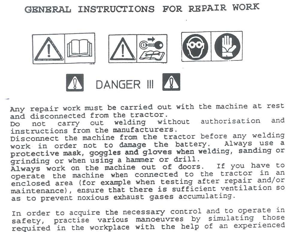
3 GUIDE TO THE SIGNS AND SYMBOLS USED THIS MANUAL AND THEIR LOCATION ON THE MACHINE IMPORTANT These signs and symbols give information to the operator on how to make the best use of the machine so as to prolong life, avoid damage, optimise work and, above all, to avoid injury to the operator and anyone within range of the machine. WARNING SIGNS 1) Before beginning operations, read the instruction manual carefully. 2) Before doing any maintenance or repair work, stop the machine at a suitable spot. Turn off the tractor motor, apply the brake, remove the key from the ignition and consult this manual. 3) This is a warning to use proper accident protection when carrying out maintenance and repairs DANGER SIGNS 4) Risk of possible ejection of blunt objects. Keep a safe distance from the machine 5) Indicates that anyone coming within range of the moving tine arms will be seriously injured. Keep a safe distance from the machine. 6) Indicates that there is a risk of crushing your hands. Keep your distance. 7) Indicates danger caused by accidental fall of suspended arms. Keep safe distance. 2

 Indicates position of the tines on the rotors and their direction of rotation. MANUAL SIGNS.")
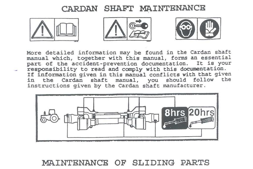
4 8) Indicates that it is dangerous to touch the cardan (P.T.O.) shaft. For all the other information regarding the cardan shaft, see the use and maintenance booklet specifically for the cardan shaft which, together with this manual, makes up the documentation on safety, use and maintenance of the machine. 9) Indicates a greasing point. INDICATION SIGNS 10) Shows the direction of rotation of the power takeoff and the maximum number revolutions. 11) Indicates position of the tines on the rotors and their direction of rotation. MANUAL SIGNS. DANGER Indicates an impending dangerous situation which, if not avoided, will cause death or severe personal injury. ATTENTION Indicates a potentially dangerous situation which, if not avoided, could cause death or severe personal injury, including dangers which are present when protection is removed. CAUTION indicates a potentially dangerous situation which, if not avoided, can provoke less severe or minor injuries. 3

5 4
6 5
7 6
8 PRODUCT IDENTIFICATION MAIN PARTS 1) BRACKET 2) DRAWBAR 3) PARKING STAND 4) HYDRAULIC KIT 5) L.H. GUARD 6) RATCHET 7) AXLE 8) R.H. GUARD 9) TINE ARM 10) TINE 11) GEARBOX 12) FRAME 13) TRANSPORT TYRES IDENTIFICATION PLATE 14) WORKING TYRES 15) CARDAN SHAFT 16) LIGHTING BRACKET 17) CYLINDER 18) CYLINDER Rotors Arms for RPM RPM Tyres Maximum Transport Working Working Power Operating WEIGHT Rotor Rotors Tractors Working Width Width Width Width DIN Required Speed X6.50 8,05 Mt 3 Mt 7,8 Mt 7,5 Mt HP Kmh Kg 1120 max 540 8PLY KW MPH lbs
9 DELIVERY AND ASSEMBLY Checking the machine on delivery All parts are carefully checked before dispatch or delivery. On receiving the machine, ensure that it has not been damaged during transport. If damage has occurred, contact the dealer concerned. Details of packing are given below. UNPACKING THE MACHINE Lift the machine using a forklift truck, crane or other suitable equipment of sufficient capacity after first checking the weight of the configurations in the table given below. Check the stability and positioning of the load on the forklift truck forks or crane hook. Keep the load as low as possible during movement for maximum stability and to ensure that the operator has maximum visibility. If a forklift truck is used, ensure that the forks are positioned as wide apart as possible. WEIGHT PACKING WEIGHT KG LBS NOTE: 1) The packing consists mainly of wood, which should be disposed of according to the laws in force in the country where the machine is used. The plastic film should also be disposed of according to the laws in force in the country where the machine is used. 2) When storing, it is permissible to stack 2-3 crates on top of each other. Make sure that they are perfectly aligned cortically. 3) In the event of further transport, ensure that the machine when on the transporting vehicle. 8
10 Assembly instructions Assembly is highly dangerous and must be carried out in strict accordance with the following instructions. We recommend that qualified personnel perform assembly. We also recommend that assembly be carried out in a flat, solid surface, open area with no people (particularly children) nearby who could be severely injured if they were to touch or move any parts of the machine. Assemblers must provide suitable lifting mechanisms and supports for stabilizing the partially assembled units, so as to prevent them from falling and causing damage or injury. The steps for assembly are illustrated in following. Depending on the experience of the assemblers and the tools available, it is not necessary that the instructions be followed in the exact order given here, but the safety precautions described above must always be followed carefully and scrupulously. Assembly sequence: Fig. 1 - Place the rotor axle (1) in a stable position and then mount the tyres support (6). Use the pivot (8) and the Seeger circlips (18) to mount support (7) and (12) on to the support so they are facing in the direction shown in the figure. Use the washer (10) and nut (11) to assemble the wheels with their guards (4) and (5) on to the tandems. Make sure that, when the wheel brackets (14) are mounted on to the supports (13), the bracket plate matches the plate divided into sectors for the various supports. Use the screw (15), the nut (17) and the washer (16) to fasten the wheel bracket into position.. 9
 to fasten the wheels on to the rear axle. After assembling the front drawbar and rear axle, mount the master cylinders (10) and (11).")
11 The wheels should face in the direction shown in the drawing. Fig. 2 - Use the pivot (3) and the elastic pin (13) to assemble the rotor group. Now assemble the transport axle with the pivots (5). Use the grommet nuts (15) to fasten the wheels on to the rear axle. After assembling the front drawbar and rear axle, mount the master cylinders (10) and (11). Use the two pivots to fasten the axle cylinder, whereas the drawbar cylinder has first to be screwed on to the support already assembled on the drawbar, and then the rear pivot is inserted. Fasten the screwing block plate over the cylinder screw, as shown in the photo. 10

.")

12 Assemble the oleodynamic system so that the tubes are arranged as shown in the following photo. Pipes should be released in this phase (the hose clamps must not be tightened ). After connecting machine to tractor, lift the machine, place hoses so that they do not force and then tighten hose-clamps. 11


13 In order to assemble the spring rods, proceed as follows: open the machine in its working position and connect the oleodynamic system to the tractor. Insert the spring rod into position and then raise the side arms. As the arm rises, it compresses the spring. Use the hole in the tube to uncover the hole on the spring guide rod. Stop the cylinder and insert the elastic pin through the hole in the rod so that the pin does not touch the tube. The following photos show the entire sequence. 12


14 Use the flat drawrod to assemble the road sign plate supports. Once assembled, the sign plates should be parallel to the ground. If not, adjust the support already assembled on the machine by unscrewing it and moving it slightly in order to get the correct position. 13
 Assemble the cardan support.")
15 Assemble the guards whit screws 28 and 48 Attach the lateral guard 54 and 53 (LH) to machine body using screws , nut 47 and washers 50. In this step, you will use: Item 46 : 1 screws M10x45 Item 47 : 1 nuts M10 Item 48 : 2 screws M12x50 Item 50 : 4 washers ø13 (ø0.51 ) Assemble the cardan support. Attach casing 1 to the central housing A and fasten using nuts 2. Attach casing 3 to the support B and fasten using screw 4 and nuts 5. Mounting cardan shaft 6 14
16 DIAGRAM OF TINE ASSEMBLY Tine bars 1 (R) are attached to rotors A C E. Tine bars 2 (L) are attached to rotors B - D F. Attach tine bars 1 2 (R-L) to the respective rotors, placing holes H of tine bars 1 2 over the screws already in place on the lower central part of rotors A B C D E F and fasten with nuts 3. Insert screws 4 in the holes G indicated on rotors A B C D E F and in tine bars 1 2 (R L) and fasten with nuts 5. Assembly is now completed. 15
17 ADJUSTMENT, PREPARATION AND USE Connection to the tractor is highly dangerous. Take great care and carry out the entire operation in strict compliance with the following instructions. Nobody should go near the area between the tractor and the machine. Check that the tractor is in good running order. Check the engine oil, gearbox oil, brake fluid and cooling water levels as well as the tyre pressures. Refer to the tractor operator s manual. ATTACHMENT MACHINE TO THE TRACTOR The attachment of pull-type machines to the tractor is very simple, as it is only necessary to couple the drawbar hitch (3) to the tractor hitch using a pin of appropriate size, strength and shape. Always use extreme care when reversing the tractor towards the machine. The drawbar hitch (3) can be set in different positions, using pin (4) turning the hitch upside-down from (A) to (B), to allow coupling to all tractor types. If the two-point crosspiece is used, lock the drawbar hitch (3) using the optional screws (10). Attention: do not use screws (10) if the machine is hitched to the drawbar. During transport and working the parking stand (7) must be shifted from position N to position K. This is done by removing clip (9) and pin (6) an moving stand (7) out of the parking position. Fasten parking stand (7) into the transport position using pin ((6) and clip (9). Once this procedure is completed, insert the quick-release coupling the tractor socket. 16
18 At this point, work carefully with the hydraulic distributor to make sure that the frame is completely lowered, and then adjust the height of the tines (H) above the ground. To change the distance between the tines and the ground, turn looking (4) and rotating the self looking nut (5), the tilt of the machine relative to the ground is adjusted. It is advised to adjust the front tine so that it is 1 3/8 from the ground. If adjustment is too high, the forage will not be completely picked up and if it is too low, the forage risks becoming dirty, the grass will be damaged and the double elastic tines will be worn down. Before starting off for work, be sure that the machine is correctly assembled and in good operating condition. 17
19 18
20 Preparation for transport To arrange machine for transport position, first it is necessary to operate movement of axle and drawbar. Valves mounted on cylinders make it possible, first partial movement of axle and then of drawbar. After this operation lift side rotors checking that safety hooks lock the relevant pins. 19
21 DISASSEMBLY OF THE TRACTOR In order to park the rake, make sure that the ground beneath it is flat and is able to bear the weight of the machine. When the rake is raised and lowered, no one should be standing between the tractor and the machine or near the machine. Before disconnecting the machine from the tractor, use the hydraulic system to lower the machine completely, then apply the brake and shut off the tractor. Dismount from the tractor and place the parking stand in the vertical position (Fig. 4). Turn the crank to raise the machine from the drawbar so that the hitch pin may be removed from the tractor. Disconnect the quick-releases coupling. Disconnect the cardan shaft and lay it against the crank. The tractor may now be moved away. Attention: the machine should be in the high position only when being transported. 20
22 21
23 22
24 USE IN THE FIELD In order to arrange machine for work it is necessary to operate rotors cylinders, so to release safety hooks and then lower rotors completely and at this point operate hydraulic system, so to lift axle and lower drawbar in order to have machine in working position. If work is not optimal adjust distance of tine from ground. If quantity of forage is high, inclination of machine may be increased acting on wheel brackets moving them in second position. Adjustment of gear speed and revs to work the machine The gear speed and machine revs depend on: the amount of forage the type of ground the degree of dryness The forage rake was designed for a maximum number of revs for the power take-off of 540 g/min. We advise working with a rev number of g/min. Gear speed should be limited so that the rake works cleanly and the swath is well formed. 23
25 24
26 25
27 MAINTENANCE POINTS Number Q.ty Description Operation Every hours Product to be used Notes 1 1 Bracket Greasing 20 Grease 2 6 Gearbox Greasing 40 Grease 3 1 Central housing Greasing 80 Grease A 4 1 Shaft Greasing Grease B 5 4 Universal joint Greasing 8 Grease 6 1 Adjustment support Greasing 20 Grease 7 4 Pin Greasing 50 Grease 8 10 Tyres Check pressure Compressor C 45 psi 9 2 Axle tandem Greasing 20 Grease 10 1 Cardan shaft Greasing 8 Grease 11 6 Rotor hubs Greasing 24 Grease 12 8 Swivel hinge pin Greasing 40 Grease 1 Cardan shaft Greasing 8 Grease General checking of bolts, security pins and split pins to be carried out initially after the first 8 hours of use. Subsequently every 50 hours and whenever the machine is laid up for extended periods. A = The complete lubrication of housing 1 is done the first time at the manufacturer s plant, after which it must be topped up periodically, as according to the lubrication points table. A complete change or fill is necessary only for the replacement and /or repairing of the entire housing or internal parts. In this case, it is necessary to: remove caps and inject the grease, using grease pump, into hole H until the grease comes out of hole K. Then screw caps back into place on housing. B = Each time the Cardan shaft is disconnected and Whenever the machine is stopped, we recommended that you clean the power takeoff shaft and replace the protective cover. C = Each time the machine is connected to the tractor. # Additives of a type permitted by anti-pollution regulations. 26
28 27
29 NOISE AND VIBRATION Noise affecting the tractor driver (from the machine only) is less than 80dB. Vibration from the machine affecting the upper body and limbs of the driver is insignificant and is lower than the values given in Point of Enclosure 1 of the Machine Directives (89/392/EEC, 91/386/EEC) THE FOLLOWING SHOULD BE NOTED IF THE MACHINE IS SCRAPPED The machine consists mainly of ferrous material, which must be disposed of according to the regulations in force in the country concerned. There is also a small amount of plastic, which must be disposed of according to the regulations in force in the country concerned. There is very small amount of residual grease, which must be disposed of according to the regulations in force in the country concerned. 28
30 Spa Zona Industriale-Viale Grecia, TRESTINA-(Perugia)-ITALY Tel Telefax sitrex@sitrex.it 1
S.p.A OPERATOR'S MANUAL SPARE PARTS LIST RP/4-RP/5-RP/6-RP/8-RP/10-RP/12
 S.p.A OPERATOR'S MANUAL SPARE PARTS LIST RP/4-RP/5-RP/6-RP/8-RP/10-RP/12 TABLE OF CONTENT 1 MOUNTED SIDE-DELIVERY RAKES: RP/4-RP/5-RP/6-RP/8-RP/10-RP/12.... 2 1.1 INTRODUCTION... 2 1.2 WARRANTEE... 2
SPARE PARTS LIST ASSEMBLY USE AND MAINTENANCE
 SPARE PARTS LIST ASSEMBLY USE AND MAINTENANCE FS SPREADER 1 The manufacturer warrants new machinery to be free from defects in material and workmanship at the time of delivery to the original purchaser
SPARE PARTS LIST (MX/8 - MX/10) 7$%/(125($53$57
 7$%/(125($53$57") 63$5(3$576/,67 0;0; 0303 7$%/(125($53$57 7$%/(125($53$57 7$%/(125($53$57 7$%/(125($53$57 7$%/(125($53$57,7(0 4W\ 4W\ 3$5712 '(6&5,37,21 127( 0; 0; 1 2 2 210.890 HEAD 2 2 2 210.932 CYLINDER BRACKET 3 9
63$5(3$576/,67 0;0; 0303 7$%/(125($53$57 7$%/(125($53$57 7$%/(125($53$57 7$%/(125($53$57 7$%/(125($53$57,7(0 4W\ 4W\ 3$5712 '(6&5,37,21 127( 0; 0; 1 2 2 210.890 HEAD 2 2 2 210.932 CYLINDER BRACKET 3 9
FINISHING MOWERS SM/ /10
 ASSEMBLY, USE AND MAINTENANCE SPARE PARTS LIST FINISHING MOWERS SM/120-150-180 02/10 WARRANTY On delivery, check that the machine has not been damaged during transport and that all the attachments are
ASSEMBLY SPARE PARTS LIST
 ASSEMBLY SPARE PARTS LIST Conversion kit RT/5200 3 rd point hitch manual fold into RT/5200 3 rd point hitch hydraulic fold part no 230.197 Conversion kit RT/5200 3 rd pull type manual fold into RT/5200
ASSEMBLY USE AND MAINTENANCE SPARE PARTS LIST QR
 ASSEMBLY USE AND MAINTENANCE SPARE PARTS LIST QR / 8-10-12 Spare parts should be ordered with serial number FROM 01/2011 1 Warranty The manufacturer warrants new machinery to be free from defects in material
ROTARY TILLER. Operation, Service & Parts Manual For "AS" Series. FORM: ASTillerBook.QXD
 ROTARY TILLER Operation, Service & Parts Manual For "AS" Series FORM: ASTillerBook.QXD April 2002 TABLE OF CONTENTS Preparation......................................1 Assembly Instructions.............................2
Operating instructions Spare parts list. Silage cutter
 Operating instructions Spare parts list Silage cutter 3 35 03 60 P 1287 EN Edition: 2010 Index Operation in accordance with specifications... 3 Safety technical advices... 4 Technical Data... 5 Description...
Mod: KLD6-12/35XLAS-N
 12/2011 Mod: KLD6-12/35XLAS-N Production code: 1914070 INSTRUCTION MANUAL LOGIC LINE PLUS HOOD Reseller Stamp for Warranty Dear customer, Above all, thank you for choosing our product and we would like
Operator s Manual. Go Galvanized! YOU'RE ALWAYS AHEAD...WITH A MODERN BEHIND.
 SUMMER 2008 spreaderrr Operator s Manual YOU'RE ALWAYS AHEAD...WITH A MODERN BEHIND. P.O. Box 790 Beaumont, Tx 77704 409.833.2665 1.800.231.8198 Fax: 409.726.8333 www.modernusa.com Go Galvanized! Spreaderrr
SB/150 - SB/165 SB/180 SB/210
 ASSEMBLY, USE AND MAINTENANCE SPARE PARTS LIST SB/150 - SB/165 SB/180 SB/210 10 WARRANTY DEAR CUSTOMER, WE WOULD LIKE TO WELCOME YOU AS OUR-PRODUCT USER AND THANK YOU FOR CHOOSING OUR MACHINE. OUR MACHINES
STOP. 44" High Speed Sweeper. Operator's Manual. Model No Safety Assembly Operation Maintenance Parts
 Operator's Manual STOP 44" High Speed Sweeper Model No. 486.029 DO NOT RETURN TO STORE For Missing Parts or Assembly Questions Call 1-866-576-8388 CAUTION: Before using this product, read this manual and
FERTILIZER SPREADERS MODEL PL180, PL400 & PL500
 FERTILIZER SPREADERS MODEL PL180, PL400 & PL500 SAFETY INSTRUCTIONS; OPERATING INSTRUCTIONS; PARTS BREAKDOWNS; ASSEMBLY; MAINTENANCE TABLE OF CONTENTS PAGE Introduction...1 Safety Decals...2 Checklists...3
SEEDER/SPREADERS TRAILER MOUNT
 SEEDER/SPREADERS TRAILER MOUNT Assembly, Operation, Service & Parts Manual For Models PTP180-P & PTP300-P Form: PTPSprdr March 2009 TABLE OF CONTENTS PAGE Introduction...1 Preparation Checklist...2 Safety
EverythingAttachments.com
 EverythingAttachments.com 60 Xtreme Duty Brush Cutter Owner s Manual SAFETY GENERAL SAFETY INSTRUCTIONS AND PRACTICES A careful operator is the best operator. Safety is of primary importance to the manufacturer
Operator s Manual. Go Galvanized! YOU'RE ALWAYS AHEAD...WITH A MODERN BEHIND.
 SUMMER 2008 C2 tilting grader blade Operator s Manual YOU'RE ALWAYS AHEAD...WITH A MODERN BEHIND. 003-5336 003-5342 003-5531 003-5544 P.O. Box 790 Beaumont, Tx 77704 409.833.2665 1.800.231.8198 Fax: 409.726.8333
1 KW-550T Parts Manual. Table Of Contents
 KW-550T Parts Manual Table Of Contents Drawbar... 2 Central Gearbox - Serial No. 523800-554988... 4 Central Gearbox - Serial No. 523800-554988... 6 Central Gearbox - Serial No. 554989-... 8 Central Gearbox
ROTARY TILLER. Operation, Service & Parts Manual For P-P/C Series. November 1996 (Rev. 4-05) FORM: PTillerBook.QXD
 FORM: PTillerBook.QXD") ROTARY TILLER Operation, Service & Parts Manual For P-P/C Series FORM: PTillerBook.QXD November 1996 (Rev. 4-05) TABLE OF CONTENTS Preparation......................................1 Assembly Instructions.............................2
ROTARY TILLER Operation, Service & Parts Manual For P-P/C Series FORM: PTillerBook.QXD November 1996 (Rev. 4-05) TABLE OF CONTENTS Preparation......................................1 Assembly Instructions.............................2
Parts Manual Woody Wood Splitter Models: and mcx
 Parts Manual Woody Wood Splitter Models: 40-30 and 40-36 4mcx Woody Equipment inc. 205, rue commercial Saint-Odilon-de-Cranbourne, Québec, Canada G0S3A0 Tél./ Tel. 418-464-2748 Fax. 418-464-2746 Email:
SERIES 04 DIAMOND HARROW PRODUCT MANUAL FOR SECTIONS & SETS
 SERIES 04 DIAMOND HARROW PRODUCT MANUAL FOR SECTIONS & SETS TABLE OF CONTENTS Welcome Note 4 Safety 5 Usage Information 7 Normal Packaging 9 Assembly Instructions 10 Operating Instructions 13 Series 04
Tube-Line Techno-Bale 980
 Tube-Line Techno-Bale 980 Operator's Manual 28287 (05/05/11) 2 One- Year Manufacturer's Warranty For Normal Use With The Exception Of Tires If the equipment does not function properly, or if a manufacturing
Operator s Manual. Go Galvanized! YOU'RE ALWAYS AHEAD...WITH A MODERN BEHIND.
 SUMMER 2008 rock & landscape rake Operator s Manual 003-7445 003-7450 003-7460 003-7440 003-7445 003-7450 YOU'RE ALWAYS AHEAD...WITH A MODERN BEHIND. P.O. Box 790 Beaumont, Tx 77704 409.833.2665 1.800.231.8198
TT4100 Rotary Tedder
 TT0 Rotary Tedder Serial numbers 0 and higher Illustrated Parts Breakdown Page Page Tongue Assembly S/N - Tongue Assembly S/N to Page Page Page Page Page Tongue Assembly S/N to Tongue Assembly S/N + Main
Original operating manual
 matev GmbH Nürnberger Str. 50 90579 Langenzenn T +49 9101 9087-0 F +49 9101 9087-20 info@matev.eu www.matev.eu Original operating manual Engine PTO Shaft FPS-PTO JD-3R for John Deere, type 3033R, 3038R,
Smart-Till. Models ST101, ST151, ST203, and ST303. HCC, inc st Avenue Mendota, IL
 Owners Manual Smart-Till Models ST101, ST151, ST203, and ST303 HCC, inc. 1501 1st Avenue Mendota, IL 61342 815-539-9371 www.hccincorporated.com C-1159 May 2010 Safety Most work related accidents are caused
Operator's Manual. VC-60 & VC-60 Plus Harper Industries, Inc. 7/03 Part No
 Operator's Manual VC-60 & VC-60 Plus 2003 Harper Industries, Inc. 7/03 Part No. 970066 Thank you for purchasing a Harper/Goossen Verti-Cutter. As with all Harper/Goossen products, the Harper/Goossen Verti-Cutter
Wheel Horse. 36 Tiller. Model No & Up. Operator s Manual
 FORM NO. 8 9 Rev. A Wheel Horse 6 Tiller for Classic Garden Tractors Model No. 7970 690000 & Up Operator s Manual IMPORTANT: Read this manual carefully. It contains information about your safety and the
RollSeal 1733 County Road 68 Bremen, Alabama Part No Rev Owner s Manual RS-Divider Curtain
 1. 2. 7 3. 4. RollSeal 1733 County Road 68 Bremen, Alabama 35033 256-287-7000 Part No 4801-5176 Rev 12-11-17 Owner s Manual RS-Divider Curtain Table of Contents 1 Warnings (Avertissements)... 3 2 Limited
Model 858-RH. Operating and Assembly Manual. Palmor Products Inc Serum Plant Road Thorntown, IN 46071
 Model 5-RH Operating and Assembly Manual Palmor Products Inc. 55 Serum Plant Road Thorntown, IN 6071 3/31/015 SAFETY RULES Remember, any power equipment can cause injury if operated improperly or if the
HR24TS Rotary Rake. Serial Numbers and higher. Illustrated Parts Breakdown. Guards and Guard Arm, Front Hay Curtain Mount.
 HRTS Rotary Rake Serial Numbers 00 and higher Illustrated Parts Breakdown Page Page Page Page Page Page Page Page Page Page 0 Page Page Page Page Page Page Page Page Page Page 0 Tongue Front Frame Guards
WARRANTY REGISTRATION AND POLICY
 WARRANTY REGISTRATION AND POLICY Buhler Manufacturing products are warranted for a period of twelve (12) months from original date of purchase, by original purchaser, to be free from defects in material
TABLE OF CONTENTS DESCRIPTION. Safety Instructions & Safety Sign Locations Operating Instructions Assembly Instructions...
 TABLE OF CONTENTS DESCRIPTION PAGE Warranty... 1 Safety Instructions & Safety Sign Locations... 2 Operating Instructions... 3 Assembly Instructions... 5 500 & 600 Snowblower Drawings... 8 500 & 600 Snowblower
Blec Bar grader Serial number: User manual and parts handbook
 User manual and parts handbook Blec Bar grader 180-240 Serial number: ATTENTION: TO ENSURE SAFE USE OF THIS MACHINE AND TO BE ABLE TO ACHIEVE THE BEST RESULTS, IT IS OF THE UTMOST IMPORTANCE TO READ THIS
USE AND MAINTENANCE MANUAL
 CLAMP FOR APPLIANCES ORIGINAL INTRODUCTION This manual contains instructions for assembly, periodic and extraordinary maintenance and troubleshooting. The instructions in this manual supplement, and do
HANDY GATE ASSEMBLY, INSTALLATION AND OPERATING INSTRUCTIONS
 ASSEMBLY, INSTALLATION AND OPERATING INSTRUCTIONS BEFORE INSTALLING OR USING THE, REVIEW THE VEHICLE LOADING LIMITATIONS OUTLINED IN THE VEHICLE OWNER S MANUAL AND THE SAFETY COMPLIANCE CERTIFICATION LABEL
TT4101 Rotary Tedder
 TT Rotary Tedder 0//0 Illustrated Parts Breakdown Page Page Page Page Page Page Page Page Page Page Page Tongue Assembly S/N S/N - Tongue Assembly S/N + Main Frame S/N - Main Frame S/N to Main Frame S/N
Original Operating Manual
 matev GmbH Nürnberger Str. 50 90579 Langenzenn T +49 (0) 9101 9087-0 F +49 (0) 9101 9087-20 info@matev.eu www.matev.eu Original Operating Manual Front Power System und Front PTO shaft FPS- JD X 950 R for
Wheel Horse 48 Blade for 5xi Garden Tractors
 Form No. -9 Wheel Horse 8 Blade for 5xi Garden Tractors Model 7955 0000000 Operator s Manual Domestic English (EN) Contents Page Introduction................................ Installation.................................
OPERATORS MANUAL FOR KAFURTER ROTARY TOPPERS MODELS: TP110, TP140, TP160, TP170
 OPERATORS MANUAL FOR KAFURTER ROTARY TOPPERS MODELS: TP110, TP140, TP160, TP170 SAFETY WARNING: Do not use or operate this this manual and assembly instructions (where applicable) has been read and understood.
MK AUGERS POWER SWING KIT ASSEMBLY & OPERATION MANUAL
 MK AUGERS POWER SWING KIT ASSEMBLY & OPERATION MANUAL Read this manual before using product. Failure to follow instructions and safety precautions can result in serious injury, death, or property damage.
Operator s Manual. Go Galvanized! YOU'RE ALWAYS AHEAD...WITH A MODERN BEHIND.
 fall 2010 3pt & quick attach Bale spears & 3pt bale carrier Operator s Manual YOU'RE ALWAYS AHEAD...WITH A MODERN BEHIND. 318-1006-i 318-1005-i 020-1500 020-1502 P.O. Box 790 Beaumont, Tx 77704 409.833.2665
Planting Components. Operator s/parts Manual. Row Cleaner VIII. Terra-Tine
 Operator s/parts Manual Terra-Tine Row Cleaner VIII Planting Components! Read the operator s manual entirely. When you see this symbol, the subsequent instructions and warnings are serious - follow without
POST HOLE DIGGER. Operation, Service & Parts Manual For Models D20 & D40. FORM: D20_40DigRev.QXD
 POST HOLE DIGGER Operation, Service & Parts Manual For Models D20 & D40 FORM: D20_40DigRev.QXD September 2006 Revised August 2009 TABLE OF CONTENTS Introduction.............................1 Preparation..............................2
Wheel Horse. 48 Snow/Dozer Blade. Model No & Up. Operator s Manual
 FORM NO. 9 878 Rev A Wheel Horse 8 Snow/Dozer Blade for 5xi Lawn and Garden Tractors Model No. 7955 890000 & Up Operator s Manual IMPORTANT: Read this manual, and your tractor manual, carefully. They contain
ROTARY MOWER OPERATION, SERVICE & PARTS MANUAL FOR
 ROTARY MOWER OPERATION, SERVICE & PARTS MANUAL FOR L-G-40-40-P, L-G-48-40-P, L-G-60-40-P & L-G-72-40-P Slip Clutch Models: L-G-60-40-SC-P & L-G-72-40-SC-P February 2003 FORM: RotMwrBook.QXD TABLE OF CONTENTS
Pro. User Manual. Safe-T-Pull Inc Page 1 of 19
 Pro User Manual Safe-T-Pull Inc. 2015 Page 1 of 19 TABLE OF CONTINENTS 1. Before You Begin...3 Disclaimer...3 What Is Included...3 Unpacking Instructions....4 Claims...4 Contact Us...4 Safety Information...4
AG PRODUCTS, LTD. YOU RE ALWAYS AHEAD... WITH A MODERN BEHIND.
 SUMMER 2016 BADGER DISC HARROW Operator s Manual 011-1156 011-1166 001-1501 001-1501-1 011-1167 001-1501-2 001-1501-3 011-1176 001-1501-4 011-1177 MODERN AG PRODUCTS, LTD. YOU RE ALWAYS AHEAD... WITH A
VR482 Hay Rake OPERATOR & PARTS MANUAL. Last Updated: May 12, 2014
 VR482 Hay Rake OPERATOR & PARTS MANUAL Last Updated: May 12, 2014 Bridgeview Manufacturing Inc. P.O. Box 4 Gerald, SK S0A 1B0 (306) 745-2711 www.bridgeviewmanufacturing.com bmi@sasktel.net Your Authorized
FOREST TRAILER PALMS 9S
 USER MANUAL FOREST TRAILER PALMS 9S Palmse Mehaanikakoda, Võsupere küla, Vihula vald, Lääne-Virumaa 45202, Estonia tel. +3723255375 fax +3723255378 e-mail: palms@palms.eu http://www.palms.eu TABLE OF CONTENTS
Edition October 2014 Part No
 Edition 1.3 - October 2014 Part No. 8999076 1 Contents Ordering Your Parts... 3 Centre Section - S180025.70... 5 Wing Section - S180025.71/72...7 Centre Axle - S180025.110... 9 Wing Axle - S180025.111...10
W & A 12 ROW TOP LEVELING STACKER LEVEL BANDER
 W & A 12 ROW TOP LEVELING STACKER LEVEL BANDER NO. 3640 OPERATOR S MANUAL TO THE OWNER: Congratulations on your purchase of a new W & A Top Leveling Stacker Level Bander. Your selection is an indication
HAMMER KNIFE FLAIL MOWER SHREDDER
 HAMMER KNIFE FLAIL MOWER SHREDDER Operation, Service, & Parts Manual For Models: GOF69, 79, 89, 98, & 108 February 2006 Rev. 2009 FORM: GOFMower.QXD TABLE OF CONTENTS Installation....................................................1
Operating Instructions & Parts Manual. Brake Drum Handler Model: 46000
 Operating Instructions & Parts Manual Brake Drum Handler Model: 46000 This is the safety alert symbol. It is used to alert you to potential personal injury hazards. Obey all safety messages that follow
MODELS EWR820, EWR1023, EWR1227 PULL TYPE HAY RAKES PARTS MANUAL SECTION 19
 EWR MODELS EWR820, EWR1023, EWR1227 PULL TYPE HAY RAKES Published 04/11 PARTS MANUAL SECTION 19 MATERIAL HANDLING PARTS MANUAL PARTS ORDERING GUIDE The following instructions are offered to help eliminate
OPERATION AND MAINTENANCE MANUAL SERIES HIGH GRASS MOWER FT
 S.p.A. OPERATION AND MAINTENANCE MANUAL SERIES HIGH GRASS MOWER www.hscmsc.co.uk CONTENTS INTRODUCTION IDENTIFICATION AND TECHNICAL CHARACTERISTICS PACKING AND TRANSPORT SAFETY RULES AND LIMITS ON USE
MODEL 7400 STRUT SPRING COMPRESSOR
 MODEL 7400 STRUT SPRING COMPRESSOR Installation, Operation & Repair Parts Information Branick Industries, Inc. 4245 Main Avenue P.O. Box 1937 Fargo, North Dakota 58103 REV112712 P/N: 81-0103A TABLE OF
11 ½" MODEL SINGLE CHAIN CONVEYOR
 11 ½" MODEL SINGLE CHAIN CONVEYOR USER S MANUAL 11 ½" Chain conveyor Revision 2011-05-31 2 CONTENTS WARRANTY...3 FOREWORD...4 SAFETY PRECAUTIONS...5 ASSEMBLY INSTRUCTIONS...6 SPECIFICATIONS...6 ASSEMBLING
3-Pt. Quick Hitch. Owner s Manual
 3-Pt. Quick Hitch Owner s Manual WARNING: Read carefully and understand all ASSEMBLY AND OPERATION INSTRUCTIONS before operating. Failure to follow the safety rules and other basic safety precautions may
BrentChalmers.com. Owner Operation and Maintenance Manual ROTARY MOWER MODEL WISCONSIN,U.S.A. PORT ATTACHMENT 28 INCH WASHI~GTON,
 ROTARY MOWER Owner Operation and Maintenance Manual ATTACHMENT 28 INCH MODEL 15100-01 (2) Do not allow children to operate powered equipment at any time. The average child is not capable of coping with
MODEL 7600 STRUT SPRING COMPRESSOR
 MODEL 7600 STRUT SPRING COMPRESSOR Installation, Operation & Repair Parts Information Branick Industries, Inc. 4245 Main Avenue P.O. Box 1937 Fargo, North Dakota 58103 REV6162014 P/N: 81-0246 TABLE OF
KONGSKILDE Vertical Tillage - Assembly Guide ASSEMBLY INSTRUCTIONS Revision 18 Serial No current Series.
 KONGSKILDE 9100 Vertical Tillage - Assembly Guide Kongskilde 9100 Series *Model may not be exactly as shown. Kongskilde reserves the right to make changes to product designs and specifications without
Planting Components. Operator s/parts Manual Terra-Tine. Row Cleaner
 Operator s/parts Manual Terra-Tine Row Cleaner Planting Components! Read the operator s manual entirely. When you see this symbol, the subsequent instructions and warnings are serious - follow without
E N G L I S H HYDRAULIC TRUCK-MOUNTED LIFT. Art. 1120/E Art. 1120/F Art. 1120/G INSTRUCTIONS FOR USE, MAINTENANCE AND SPARE PARTS A 01 03
 HYDRAULIC TRUCK-MOUNTED LIFT E N G L I S H Art. 1120/E Art. 1120/F Art. 1120/G INSTRUCTIONS FOR USE, MAINTENANCE AND SPARE PARTS A 01 03 Before use, place on the lift the adhesive labels enclosed with
HT46X Rotary Tedder. Illustrated Parts Breakdown. Center Section
 HTX Rotary Tedder Illustrated Parts Breakdown Page Page Page Page Page Page Page Page Page Page 0 Page Center Section Hydraulics Outer Wing Assembly Center Bolted Components Tine Rotor and Hardware Tilt
Original. User Manual & Install Guide. Safe-T-Pull Inc. Page 1 of 15
 Original User Manual & Install Guide Safe-T-Pull Inc. Page 1 of 15 TABLE OF CONTINENTS 1. Before You Begin...3 Disclaimer...3 What Is Included...3 Claims...3 Contact Us...4 Safety Notes...4 2. Introduction...5
USE AND MAINTENANCE MANUAL
 LATERAL TURNOVER 360 ORIGINAL INSTRUCTIONS INTRODUCTION This manual includes instructions for assembly, maintenance (regular and extraordinary), and for possible faults with remedies. The instructions
60in. Acreage Rake. Owner s Manual
 60in. Acreage Rake Owner s Manual WARNING: Read carefully and understand all ASSEMBLY AND OPERATION INSTRUCTIONS before operating. Failure to follow the safety rules and other basic safety precautions
Spraying boom INDEX. Booklet. user manual. equipment general description... 2 technical specifications... 2
 Booklet 9 Spraying boom Serial number Edition 2 07-2008 INDEX title page title page TECHNICAL INFORMATION... 2 equipment general description... 2 technical specifications... 2 Technical specification diagram...
Original Operating Manual
 matev GmbH Nürnberger Str. 50 90579 Langenzenn T +49 (0) 9101 9087-0 F +49 (0) 9101 9087-20 info@matev.eu www.matev.eu Original Operating Manual Snow blade SRM-FB 120 CD Angle adjustment mechanical Version
USE AND MAINTENANCE MANUAL
 ORIGINAL INSTRUCTIONS BALE CLAMP - FORK CLAMP - HAND ROTATING FORK CLAMP - FOR FOAM BLOCKS INTRODUCTION This manual contains instructions for assembly, periodic and extraordinary maintenance and troubleshooting.
STOP 42" HIGH SPEED LAWNSWEEPER. Owner's Manual. Model No's Safety Assembly Operation Maintenance Parts
 Owner's Manual STOP 42" HIGH SPEED LAWNSWEEPER Model No's. 486.242223 DO NOT RETURN TO STORE For Missing Parts or Assembly Questions Call 1-866-576-8388 CAUTION: Before using this product, read this manual
SHAW-BOX INSTRUCTIONS AND PARTS LIST SHAW-BOX RIGID MOUNT I-BEAM AND PATENTED TRACK TROLLEYS (PUSH & HAND GEARED - 1/2 THRU 15 TON RATED LOADS)
") SHAW-BOX INSTRUCTIONS AND PARTS LIST SHAW-BOX RIGID MOUNT I-BEAM AND PATENTED TRACK TROLLEYS (PUSH & HAND GEARED - 1/2 THRU 15 TON RATED LOADS) GENERAL SHAW-BOX Rigid Mount I-Beam Trolleys are designed
SHAW-BOX INSTRUCTIONS AND PARTS LIST SHAW-BOX RIGID MOUNT I-BEAM AND PATENTED TRACK TROLLEYS (PUSH & HAND GEARED - 1/2 THRU 15 TON RATED LOADS) GENERAL SHAW-BOX Rigid Mount I-Beam Trolleys are designed
DEBRIS BLOWER 2613 BLOWER ASSEMBLY PARTS CATALOG MODEL NO & UP. The TORO Company All Rights Reserved. FORM NO Rev.
 FORM NO. 01-505-0440 Rev. D MODEL NO. 44520-20101 & UP PARTS CATALOG DEBRIS BLOWER 2613 Part 1 61-005-0073 Hitch & Lower Housing 1 2 61-005-0121 Fan Housing 1 3 61-005-0061 Fan Assembly 1 4 01-113-0070
Tube-Line Techno-Bale 960. Operator's Manual
 Tube-Line Techno-Bale 960 Operator's Manual One- Year Manufacturer's Warranty For Normal Use With The Exception Of Tires If the Equipment does not function properly, or if a piece is defective due to a
GROUNDSMASTER. 52 Recycler. for 120 Traction Unit. Model No & UP. Operator s Manual
 FORM NO. 8-980 Rev A GROUNDSMASTER 5 Recycler for 0 Traction Unit Model No. 077 79000 & UP Operator s Manual IMPORTANT: Read this manual carefully. It contains information about your safety and the safety
Twin Screw Undercar Conveyor
 Twin Screw Undercar Conveyor Owner s Manual #19015700 05-00 Table of Contents Operator Qualifications...................................... 1 Safety.................................................. 2-4
Operating instructions Actuator and Emergency exit AZ/AZM 200-B30 AZ/AZM 201-B About this document. Content
 1. About this document Operating instructions............pages 1 to 10 Original 1.1 Function This operating instructions manual provides all the information you need for the mounting, set-up and commissioning
Part Number Mini Linear Lift Assembly Installation & Operator s Instruction Manual
 Part Number 39644 Mini Linear Lift Assembly Installation & Operator s Instruction Manual April 1999 MV1505C Chore-Time Warranty Mini Linear Lift Assembly Manual Chore-Time Warranty Chore-Time Equipment
BEFCO. Operator s Manual BABY HOP & HOP FERTILIZER SPREADERS ACCESSORIES SIDE ROW DISCHARGE. AA4-120 (fits models Hop 209 & 212) DEFLECTOR
 DEFLECTOR") BEFCO Operator s Manual BABY HOP & HOP FERTILIZER SPREADERS ACCESSORIES SIDE ROW DISCHARGE AA-0 (fits models Hop 09 & ) DEFLECTOR AA-0 (fits models Baby Hop 0 & 06) 009-95 (fits models Hop 0 & 06) 009-968
BEFCO Operator s Manual BABY HOP & HOP FERTILIZER SPREADERS ACCESSORIES SIDE ROW DISCHARGE AA-0 (fits models Hop 09 & ) DEFLECTOR AA-0 (fits models Baby Hop 0 & 06) 009-95 (fits models Hop 0 & 06) 009-968
ENGINE DRIVEN ROTARY MOWER
 ENGINE DRIVEN ROTARY MOWER Operation, Service & Parts Manual For Models ERM-413, 416, & 617 April 2009 Form: ERMHydMower TABLE OF CONTENTS SECTION DESCRIPTION...PAGE 1 Introduction... 1 2 Preparation...2
ROTARY RAKE PARTS BOOK MODEL E
 ROTARY RAKE PARTS BOOK MODEL 1150 17.00803E This parts book is furnished for your convenience only. All parts must be purchased through an authorized dealer. Call us for a dealer near you. Issue Date:
Operating instructions. Grip fork FC
 Operating instructions Grip fork FC 1 Danger Read the entire operating manual before using the front loader. 3 54 26 80 P 1524 EN Table of contents Operation in accordance with specifications... 3 Safety
Parts Manual. Ransomes Gang Mower G (rev.0)
") 25054G (rev.0) Parts Manual Ransomes Gang Mower Sportcutter Mk11, Magna Mk13 Product codes: LBMA171 Sportcutter Gang unit on pneumatic wheels LBMA172 Sportcutter Gang unit on steel wheels LJBA003 Sportcutter
25054G (rev.0) Parts Manual Ransomes Gang Mower Sportcutter Mk11, Magna Mk13 Product codes: LBMA171 Sportcutter Gang unit on pneumatic wheels LBMA172 Sportcutter Gang unit on steel wheels LJBA003 Sportcutter
Owner s Manual. Powered Dandy Lifts PLM-100, PLM100W, PLM150, PLM-150W. (See separate manual for PLM-250) Model # Serial #
 Model # Serial #") Owner s Manual Powered Dandy Lifts PLM-00, PLM00W, PLM50, PLM-50W (See separate manual for PLM-250) Model # Serial # Southworth Products Corp P.O. Box 380/Portland, Maine 0404-380 Phone 800-743-000 FAX
Owner s Manual Powered Dandy Lifts PLM-00, PLM00W, PLM50, PLM-50W (See separate manual for PLM-250) Model # Serial # Southworth Products Corp P.O. Box 380/Portland, Maine 0404-380 Phone 800-743-000 FAX
Pequea Turbo Tedder. Model TT2101. Operator s Manual THIS MANUAL MUST BE READ AND UNDERSTOOD BEFORE ANYONE OPERATES THIS MACHINE!
 Pequea Turbo Tedder Model TT2101 Operator s Manual THIS MANUAL MUST BE READ AND UNDERSTOOD BEFORE ANYONE OPERATES THIS MACHINE! PN: 990044 Revised 7/5/2017 YOU MUST FILL OUT YOUR WARRANTY REGISTRATION
Directions for use VIBRO FLEX 7400
 Directions for use VIBRO FLEX 7400 Contents Introduction... 3 Identification... 3 Explanation of symbols... 4 Safety... 5 General safety advice... 5 Coupling and uncoupling... 5 Three-point hitch or linkage...
2¼ TONNE TROLLEY JACK
 2¼ TONNE TROLLEY JACK Model No: CTJ2250LP PART NO: 7623070 OPERATING & MAINTENANCE INSTRUCTIONS GC01/12 INTRODUCTION Thank you for purchasing this CLARKE Trolley Jack. Before attempting to use this product,
Operating and Assembly Manual
 Model 1080 Operating and Assembly Manual Midwest Equipment Manufacturing, Inc. 5225 Serum Plant Road Thorntown, IN 46071 08-02-16 SAFETY RULES Remember, any power equipment can cause injury if operated
GRADING SCRAPERS INDUSTRIAL SERIES OPERATION, SERVICE & PARTS MANUAL FOR MODELS: GSI7-SS, GSI7, GSI8, GSI10, & GSI12.
 GRADING SCRAPERS INDUSTRIAL SERIES OPERATION, SERVICE & PARTS MANUAL FOR MODELS: GSI7-SS, GSI7, GSI8, GSI10, & GSI12 September 2006 FORM: IndGradingScrpr.QXD TABLE OF CONTENTS Safety Information......................1-2
Berta Flail Mower Attachment. BCS Power Units
 Manufactured by Berta s.r.l. to fit BCS Power Units Operating Instructions Before commissioning the machine, read operating instructions and observe warning and safety instructions. PLEASE ALSO READ ORIGINAL
1 HR-301/D Parts Manual. Table Of Contents
 Table Of Contents 301/D Parts Manual 3 Point Hitch...2 Pull-Type Hitch...4 Main Frame...6 Angle Adjuster - Serial Number 44982 & Prior...8 Rotor Assembly - Serial Number 44982 & Prior...10 Rotor Assembly
LOG SPLITTER. Heavy Duty PTO Driven. Owners Illustrated Instruction Book & Parts List
 LOG SPLITTER Heavy Duty PTO Driven Owners Illustrated Instruction Book & Parts List Grovebury Road, Leighton Buzzard, Bedfordshire. LU7 4UX. UK. Tel:01525 375157. Fax:01525 385222. Email: enquires@brownsagricultural.co.uk
ProLine. 44 Mower. for 120 Traction Unit. Model No & Up. Operator s Manual
 FORM NO. 9 ProLine Mower for 0 Traction Unit Model No. 05 99000 & Up Operator s Manual IMPORTANT: Read this manual carefully. It contains information about your safety and the safety of others. Also become
Spearhead Multicut 460 MULTICUT th Edition - July 2015 Part No
 MULTICUT 460 14 th Edition - July 2015 Part No. 8999023 1 Spearhead Multicut 460 Parts Book 14 th Edition July 2015 Spearhead Machinery Ltd Green View Salford Priors Evesham Worcestershire WR11 8SW Tel:
Low Profile Service Jack Jack Stand Combo
 Low Profile Service Jack Jack Stand Combo Jack Stands Low Profile Service Jack U.S. Patent No. 6,199,379! This is the safety alert symbol. It is used to alert you to potential personal injury hazards.
Pequea Turbo Tedder. Model TT4100 &TT4101. Operator s Manual THIS MANUAL MUST BE READ AND UNDERSTOOD BEFORE ANYONE OPERATES THIS MACHINE!
 Pequea Turbo Tedder Model TT4100 &TT4101 Operator s Manual THIS MANUAL MUST BE READ AND UNDERSTOOD BEFORE ANYONE OPERATES THIS MACHINE! Manual# 990039 Revised 07/08/2016 YOU MUST FILL OUT YOUR WARRANTY
AERO AIR TIRE PEDAL CAR. Assembly Instructions Model # USA. Tools Required: Recommended for children up to 200 lbs, ages 5-9
 AERO AIR TIRE PEDAL CAR Assembly Instructions Model # 998-700 USA Printed on 00% recycled paper! Recommended for children up to 200 lbs, ages 5-9 Tools Required: (pliers) (phillips head screwdriver) AERO
Quiet Collector. Model No & Up
 FORM NO. -8GB Rev A Quiet Collector Model No. 795-890000 & Up Operator s Manual IMPORTANT: Read this manual, and your tractor manual, carefully. They contain information about your safety and the safety
M MODEL FORK POSITIONERS
 Index: INTRODUCTION SPECIFICATIONS AND USE OF THE EQUIPMENT 1. RECOMMENDATIONS FOR USING THE EQUIPMENT 1.1 PROHIBITED MOVEMENTS 1.2 CORRECT MOVEMENTS 2. ATTACHMENT CONFIGURATION 3.INSTALLING THE POSITIONER
Mounting and Operating Instructions EB EN. Type 3271 and Type 3277 Pneumatic Actuators. Actuator areas: 175v2, 350v2, and 750v2 cm²
 Type 3271 and Type 3277 Pneumatic Actuators Actuator areas: 175v2, 350v2, and 750v2 cm² Translation of original instructions Type 3271 (left) and Type 3277 (right) Pneumatic Actuators Mounting and Operating