DynaCon Instruction Manual
|
|
|
- Easter Mason
- 5 years ago
- Views:
Transcription


1 DynaCon Instruction Manual
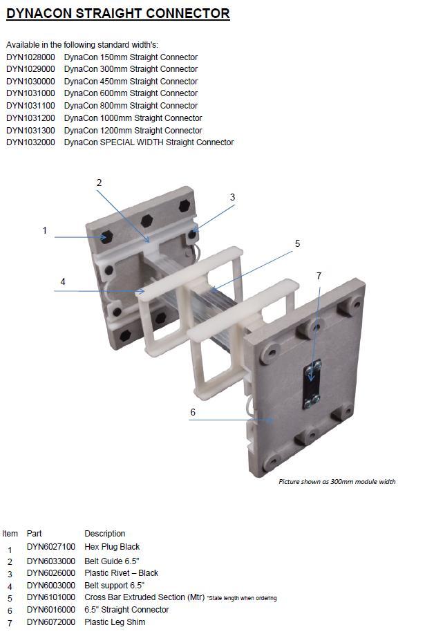
2 Table of Contents Technical Specification & Warranty Construction, Benefits & Safe Operating Procedures... 4 Noise Levels... 5 Installation, Operation & Maintenance... 5 Before you start assembling... 5 Configuration & connection of conveyors... 6 Belt Installation... 6 Standard Belt... 7 Belt with hold down tabs... 7 Radius Turn Module... 8 Adjusting belt tension... 9 Part Descriptions DynaCon Straight Connector Page 2
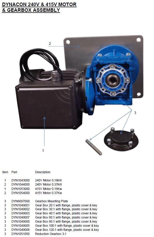
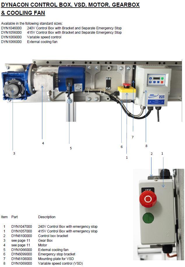
3 Technical Specifications Standard Motor: kw 3 phase motor with 80:1 gearbox external Mount kw 1 phase motor with 80:1 gearbox external Mount Belt Surface: - Intralox Series 900 & 1600 Modules: - Tough Engineering Thermoplastic Support Frame: Standard Control: - Aluminium 40 x 40mm profile - DOL 3 phase 415 volt 50Hz with externally mounted Emergency stop - DOL 1 phase 240 volt 50Hz with externally mounted Emergency stop - VSD control ( m/min) 240 volt 50Hz with externally mounted Emergency stop Special motors & controls are available, please ask your Fleming Dynamics (FD) Representative for more information. The information contained in this manual is provided only as an aid and service to our customers. Fleming Dynamics Pty Ltd (FD) does not warrant the accuracy or applicability of such information and is not specifically responsible for property damage and/or personal injury inflicted directly or indirectly, or for damages and/or failures caused by improper application, installation, operation, abuse and/or misuse of its products whether or not based on information contained herein. WARRANTY Fleming Dynamics Pty Ltd (FD) warrants products of DynaCon s manufacture for a period of five (5) years from date of shipment to the extent that FD will repair or replace any products that have failed under normal use due to faulty material or defective workmanship. Motors, electrical components and belt carry the manufacturer s warranty of one (1) year from date of shipment. No other warranty is expressed or implied unless otherwise set forth in writing and approved by a representative duly authorized to extend such approval by Dynamic Conveyor Corporation. LIMIT OF LIABILITY In no event shall Fleming Dynamics Pty Ltd (FD) be liable for any special, indirect, incidental, or consequential damages of any character, including but not limited to loss of production facilities or equipment, lost profits, property damage, lost production, or any consequential downtime, whether suffered by distributor or third party, irrespective of whether claims or actions for such damages are based upon contract, warranty, tort (including negligence), strict liability, or otherwise. FOR YOUR RECORDS Thank for your investment in DynaCon products. We believe our product will become a vital step in your production process and it will grow with your changing needs. Please take the time to complete the following information as thoroughly as possible. It will prove helpful when you call a customer service representative in the event you have any questions about assembly, installation or operation. DATE OF SHIPMENT (Warranty start date) SERIAL NUMBER (found on opposite side of motor) Page 3
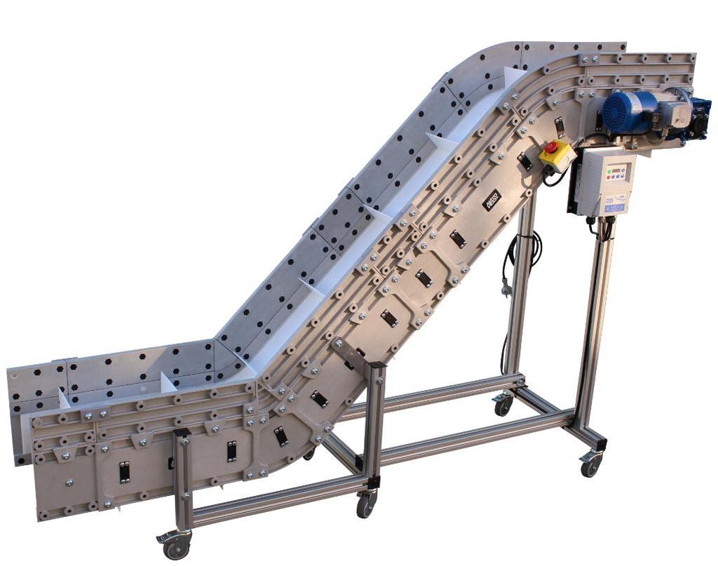
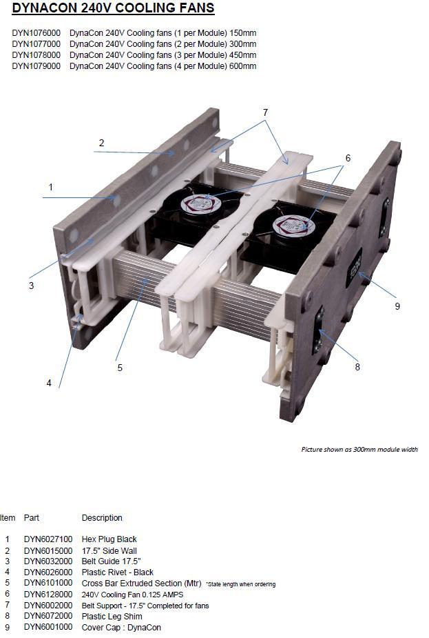
4 Construction The DYNACON conveyor system modules are constructed from tough engineering thermoplastics and are bolted together using dome headed 10mm bolts. The track assemblies are connected to one another by aluminium crossbars and polypropylene belt supports are integral to the crossbars. The belt is made from individual links, which are interconnected and laced together using polyester rods, and closed off at each end with clips. The outside edges of the belt run inside a moulded track along the total length of the conveyor. The modules are available from 100mm wide increasing in approximately 50mm increments Up to 1500mm wide. The conveyor can be assembled to achieve 30, 45, 60, 75 and 90-degree angle or swan neck configurations. Side guard extensions are available 100mm high and are fixed to the track assembly modules by using 10mm dome headed bolts and can be fitted at any time. All track assemblies are moulded with spare threaded holes (10mm) and so support frames, controls, chutes etc. Support frames are custom built from extruded aluminium profile 40x40mm, which is of a unique FD design. The DynaCon conveyor system is relatively lightweight although this manual cannot give details of mass, as this is dependent upon the configuration of the conveyor or conveyor system. BENEFITS Modular construction providing full flexibility for changing needs. All Intralox series 900 & 1600 belts can be used. Belt surfaces are impervious to oil and water. Positive gear drive motors with single phase or three phase motor drive eliminates belt slip often caused by oil or water on traditional belt materials. No tracking required. Belt surface resilient to sharp objects. Under belt or tunnel metal detectors available as standard. Under or over belt cooling fans available. Water bath conveyor construction available. Side guarding. Counting and indexing conveyor systems available. SAFE OPERATING PROCEDURES The DynaCon Conveyor presents no special hazards or dangers to the machine operator and no personal protective equipment is required for normal use of the machine. The standard motor which drives the belt is 1.8kw the drive is through a standard 80:1 gearbox with a torque of 34Nm.. Severe injury could be caused if the operator s hair or clothing were to become caught in the belt track whilst the machine is running. Long hair should be tied back or a hair net should be worn if the operator head is likely to be in close proximity to the conveyor. Never reach under the conveyor whilst it is running as loose fitting garments or jewellery may become snagged in the belt track. Never perform maintenance activities on any part of the machine whilst the power supply is connected. Never remove covers from controls whilst the power supply is connected and only qualified personnel should remove covers in any event. Page 4
5 Only suitable qualified personnel should perform any maintenance activity. Do not operate a standard machine in wet conditions check with your supplier or direct with FD if you are unsure of the machine specification and its ability to work in wet environments. QUOTE THE CONVEYOR SERIAL NUMBER WHEN MAKING ANY TECHNICAL ENQUIRY NOISE LEVELS No data is available as the noise from a DynaCon conveyor of any configuration is below background noise levels in most environments. INSTALLATION Most DynaCon conveyors are supplied with wheels for ease of movement, although this is not always the case. Place the conveyor in the correct location. A suitably qualified person should make the electrical connections as per circuit diagram or instructions supplied with the conveyor. DynaCon conveyors are supplied with mains cable and plug for all Australian conveyors installed. The conveyor should be level and stable before attempting to start the machine. OPERATION DynaCon conveyors are designed to operate continuously in a forward direction, i.e., product is conveyed toward and discharged off of the motorized module (Drive Module), with capability for occasional reversing. If your conveyor requires continuous operation in a reverse direction, please contact FD for recommendations. MAINTENANCE DynaCon conveyors are designed to be easy to maintain and repair. To ensure proper operation, we recommend periodically inspecting the frame, motor, and belt paths for wear and damage. Under ordinary operating conditions, the belt and conveyor frame should be checked for any abnormal wear or stress (i.e., continuous grooves, cracks, etc.). No lubrication of the belt or belt paths is necessary. Under high speed or continuous use conditions, more frequent inspection is encouraged. Under dirty or greasy operating conditions, a daily inspection along with periodic cleaning of the belt, belt paths, and belt support is recommended. This will require removal of the belt in most cases. Note: DynaCon Conveyors are not intended for use in abrasive environments. Necessary steps should be taken to correct any problems as soon as they are discovered. Any questions or concerns may be directed to your local sales representative and/or a customer service technician. BEFORE YOU START ASSEMBLING 1. IMPORTANT: Every DynaCon conveyor requires a minimum of two assemblers. 2. Locate an area where you will have ample space to lay out the conveyor. 3. Follow the step-by-step directions on the proceeding pages. 4. REMEMBER: Your DynaCon conveyor configuration may differ from the following examples shown. 5. If you have any questions while assembling your conveyor, call FD. Page 5


 piece sections. 4. Assemble conveyor according to drawing. Reference picture # 2 5.")
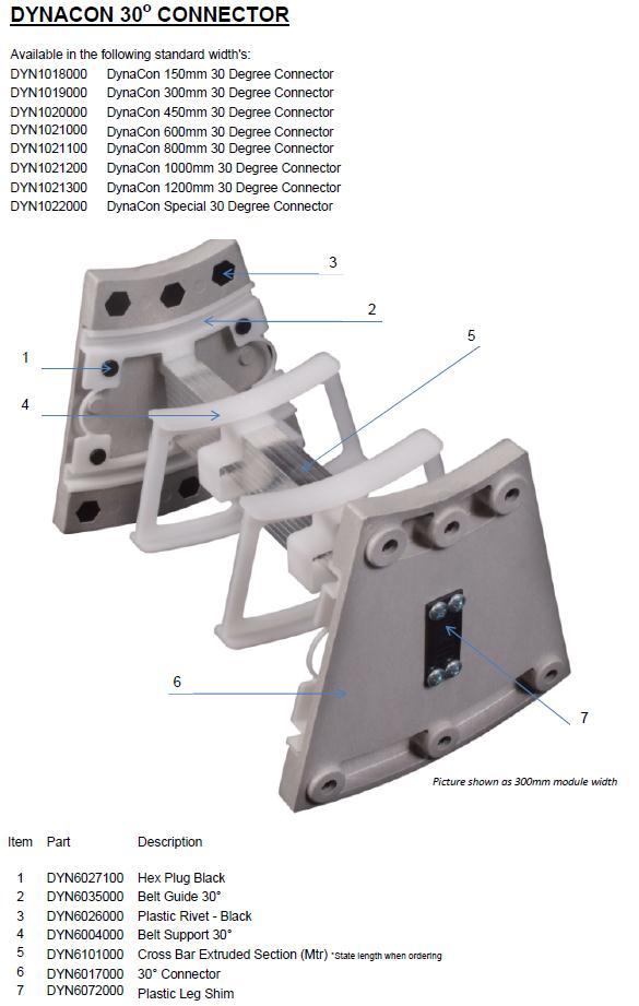
6 CONFIGURATION OF THE CONVEYOR 1. Reference the drawing of your conveyor to determine the proper position of each module. Reference picture #1 2. All DynaCon conveyors consist of a Drive Module, Feed End Module, and depending upon the length of the conveyor, Mid-Modules. 3. Begin by placing the Drive Module on the far end of the arrangement. 4. Lay all Mid-Modules in the proper configuration. 5. Continue placing modules in the intended configuration ending with the Feed End Module at the opposite end of the Drive Module. CONNECTING THE CONVEYOR MODULES Slightly loosen the two screws in doubling links on both sides of each module. Reference picture #2. 1. Determine the modules that leg sets are to be attached to according to drawing provided. 2. Connect each leg set module to one adjoining module. 3. If applicable, connect any remaining modules in two (2) piece sections. 4. Assemble conveyor according to drawing. Reference picture # 2 5. Insert M10x25mm button head screws & flat washer (that are located in holes next to attachment point) at the attachment points. Tighten all screws on every doubling link. BELT INSTALLATION If the underside of your belt has factory installed hold-down tabs, proceed to appropriate section. If your conveyor configuration includes a Radius Turn Module, proceed to appropriate section. Page 6

7 STANDARD BELT 1. Remove the Feed End sides and belt guides by removing three button-head screws on each side. Reference picture #4. Note that one screw is longer than the other two. 2. Slide belting into the belt path on the top side of the Feed End Module. Feed belt to the end of the Drive Module, making sure that drive sprockets are engaged. 3. Guide the belt along the underside of the conveyor. 4. Bring belting together. The ends should interlock without much effort. If the ends overlap, remove the necessary number of links. Punch out a lacing rod from the end without a head on it. (Radius Turn belt lacing rod is without a head on either end you can pull out rod from either end.) Retain any extra rows for use as replacement parts. Reference picture # 5 Lace belting together using the provided rod. Be sure the head snaps into place. 5. Place feed end sides back into position and attach with removed screws. Tighten completely. BELT WITH HOLD-DOWN TABS Hold-down tabs are installed some belts 600mm wide and above. They are used to support the belt as it travels on the underside of the conveyor. 1. Same as above Standard Belt instructions. 2. Slide belt into paths at the top side of the feed end module making sure hold down tabs locate centrally in the two centre belt supports. 3. Guide the belt along the top of the conveyor. Feed belt to drive sprockets making sure they engage with sprockets correctly. 4. Bring belting together. The ends should interlock without much effort. Note: If the ends overlap, remove the necessary number of links. Punch out a lacing rod from the end without a head on it. Reference picture # 5. Retain any extra rows for use as replacement parts. 5. Place belting together using the provided rod. Be sure the head snaps into place. 6. Place feed end sides back into position and attach with removed screws. Tighten completely. Page 7

8 RADIUS TURN MODULE 1. Remove the Feed End sides and belt guides by removing three button-head screws on each side. Reference picture #9. Notice that one screw is longer than the other two. 2. Align belt supports along the entire length of the conveyor. 3. Slide belting into the belt path on the top side of the Feed End Module. 4. Pull belting from the outer most arc. Reference picture #4 Note: Radius turn drives operate in forward position only. IMPORTANT: The teeth on a Radius Turn sprocket are not evenly spaced. Determine the larger of two adjoining spaces. Reference picture #10.. Fit the rod section on the belt in the larger space on the sprocket. The sprocket must be fitted to the belt in this manner for proper tracking. 6. Guide the belt along the underside of the conveyor. Reference picture #10 7. Bring belting together. The ends should interlock without much effort. Note: If the ends overlap, remove the necessary number of links by pulling out a lacing rod. The Radius Turn belt lacing rod is without a head on either end. You can pull from either end. Retain any extra rows for use as replacement parts. 8. Place feed end sides back into position and attach with removed screws. Tighten completely. Note: Belts will elongate from 0.5% to 1% of their total length during the break-in period. This usually occurs during the first several days of operation. If belt elongation is excessive, it may be necessary to remove one or more rows of belt modules in order to maintain adequate belt tension. Page 8


9 ADJUSTING THE BELT TENSION ON STANDARD FEED A minimal amount of slack is needed for smooth operation of the belt. Too much tension or slack may yield poor performance. Some belts may not require adjustment. 1. With end sides and end belt guides removed, loosen the adjustment spacer screw that holds the idler shaft in position. Adjust one side at a time. Reference picture # Increase tension by moving the spacer and idler shaft assembly to the outer position, away from the motor. 3. Line up adjustment spacer pins with holes in bracket. Reference picture #12. Tighten screw and repeat for other side. Reference picture # If additional belt tension is needed, remove a row of belting and slide adjustment spacer and idler shaft assembly to inner position. Note: It may be necessary to repeat the tension adjustment procedure as the belt may stretch over time. 5. Once proper tension is achieved, place belt end guides in position. 6. Place end sides over belt guides and secure them with the button-head screws. Page 9
10 Page 10
11 Page 11
12 Page 12
13 Page 13

14 Page 14
15 Page 15
16 Page 16
17 Page 17
18 Page 18
19 Page 19
20 Page 20
21 Page 21
22 Page 22
Assembly Instructions
 Assembly Instructions Revision 4: 2016 TABLE OF CONTENTS Important Information 5 Warranty 5 Limit of Liability 5 For Your Records 5 Operation 5 Maintenance 6 When Your Shipment Arrives 6 Tools & Personnel
Food Processing Conveyor Guidelines
 Food Processing Conveyor Guidelines Revision 3: 2017 TABLE OF CONTENTS Belt Installation Plastic Link Style. 10 Belt Installation ThermoDrive... 8 Belt Removal Plastic Link Style.. 10 Belt Removal ThermoDrive.
Universal Bench-top Conveyor OPERATOR S GUIDE
 OPERATOR S GUIDE DISCLAIMER LIABILITY LIMITATION: The Buyer of this product accepts full responsibility and understanding for the terms and specifications set forth herein. Con-Trol-Cure makes no claim,
Adjustable Angled Incline Conveyor Owners Manual with Operating Instructions
 Adjustable Angled Incline Conveyor Owners Manual with Operating Instructions Revision 012211 Table of Contents Basic Conveyor Features 3 Getting Started 4 Setting Up the Incline Conveyor 5 Belt Removal
Elgin Hydraulic Clutch-Brake ECB-240, Product Number FORM NO. L F FORM NO. L F-0704
 Elgin Hydraulic Clutch-Brake ECB-20, Product Number 96225 FORM NO. L-20283-F-070 1 FORM NO. L-20283-F-070 In accordance with Nexen s established policy of constant product improvement, the specifications
WARRANTY REGISTRATION AND POLICY
 WARRANTY REGISTRATION AND POLICY Buhler Manufacturing products are warranted for a period of twelve (12) months from original date of purchase, by original purchaser, to be free from defects in material
TABLE OF CONTENTS DESCRIPTION. Safety Instructions & Safety Sign Locations Operating Instructions Assembly Instructions...
 TABLE OF CONTENTS DESCRIPTION PAGE Warranty... 1 Safety Instructions & Safety Sign Locations... 2 Operating Instructions... 3 Assembly Instructions... 5 500 & 600 Snowblower Drawings... 8 500 & 600 Snowblower
SUNTURA HD SOLAR TRACKER
 WindyNation SUNTURA HD SOLAR TRACKER SOT-TRKS-NFHD User s Manual Page 1 of 11 WindyNation 08/09/2012 Table of Contents 1! Introduction... 3! 1.1! Limited Warranty... 3! 1.2! Restrictions... 3! 1.3! Warranty
RED23305 Owner s Manual
 RED23305 Owner s Manual 5 foot, 3-Point Mounted Snow Blower 270 West Park Avenue Huron, SD 57350 866-526-5682 Serial Number: Date of Purchase: Red Devil Snow Blower See Figure 1. 1. The Red Devil Snow
SUNTURA SOLAR TRACKER
 WindyNation SUNTURA SOLAR TRACKER SOT-TRKS-NF User s Manual Page 1 of 10 WindyNation 08/09/2012 Table of Contents 1 Introduction... 3 1.1 Limited Warranty... 3 1.2 Restrictions... 3 1.3 Warranty Claims
p.t.o. Slip clutch Read this material before using this product. Failure to do so can result in serious injury. Save this manual.
 p.t.o. Slip clutch 65517 Installation Instructions Distributed exclusively by Harbor Freight Tools. 3491 Mission Oaks Blvd., Camarillo, CA 93011 Visit our website at: http://www.harborfreight.com Read
Straight-Bore Clutch LSCC-32, 44, 54
 Straight-Bore Clutch LSCC-32, 44, 54 1 In accordance with Nexen s established policy of constant product improvement, the specifications contained in this manual are subject to change without notice. Technical
QUESTIONS? PATENT PENDING. Model No. WESY85100 Serial No. Write the serial number in the space above for future reference.
 PATENT PENDING Model No. WESY85100 Serial No. Write the serial number in the space above for future reference. Serial Number Decal-- QUESTIONS? As a manufacturer, we are commiffed to providing complete
James Barone Racing Aftermarket Parts and Accessories
 Page1 James Barone Racing Aftermarket Parts and Accessories What you will need: 2014+ Mazda 3, 6 and CX-5 Adjustable Rear Camber Arm Installation Instructions. Jack, jack stands Socket wrench Socket wrench
MV Series Motors Operation & Parts Manual. Models M3V, M5V, M5V-US
 MV Series Motors Operation & Parts Manual Models M3V, M5V, M5V-US Introduction This manual pertains to drum pump motors MV Series. Finish Thompson, Inc. thanks you for choosing our products. We believe
ActuLink ABS Module - ABS-MOD-400
 Installation Instructions ActuLink ABS Module - ABS-MOD-400 For more information on the installation and operation of Tuson s towable ABS system, consult the installation and operations manuals for the
Gauge Adapter Instruction Manual
 Instruction Manual MODELS: CF3812, CF3812E, CF3814 & CF4514 CF3812-M1_092017! This is the safety alert symbol. It is used to alert you to potential personal injury hazards. Obey all safety messages that
Vertical Stacking System for both Floor and Roof Lines. SQ-1 INTELLIGENT STACKERS. Operators Manual
 Vertical Stacking System for both Floor and Roof Lines. SQ-1 INTELLIGENT STACKERS Operators Manual FOREWORD This manual explains the proper maintenance of Square 1 Design Intelligent Stacking System as
OWNER'S MANUAL. Please Do Not Return This Product To The Store!
 TABLE TENNIS TABLE MODEL NO. T87 OWNER'S MANUAL 1. Read this manual carefully before starting assembly. Read each step completely before beginning each step. 2. Some smaller parts may be shipped inside
ALULIFT Portable Aluminium Gantry Crane Operation & Maintenance Instructions
 ALULIFT Portable Aluminium Gantry Crane Tel: +44 (0)115 932 7010 Fax: +44 (0)115 9306263 Email: sales@metreel.co.uk Website: www.metreel.co.uk CONTENTS Caution...3 Pre-Build Check List...4 Initial Set
Owner s Manual: PS4000 4,000 LB. WINCH
 Owner s Manual: PS4000 4,000 LB. WINCH PIERCE ARROW INC. 549 U.S. HWY 287 S. HENRIETTA, TEXAS 76365 ---------------------------------------------------- TOLL FREE 800-658-6301 FAX 940-538-4382 ----------------------------------------------------
PUSH BUTTON KEY CABINET
 PUSH BUTTON KEY CABINET Model 95689 INSTALLATION And Operation Instructions Due to continuing improvements, actual product may differ slightly from the product described herein. 3491 Mission Oaks Blvd.,
FTFR Maintenance and Parts Manual SQ-1 FLOOR TRUSS FINISH ROLLER. Operators Manual
 FTFR Maintenance and Parts Manual SQ-1 FLOOR TRUSS FINISH ROLLER Operators Manual FOREWORD This manual explains the proper maintenance of Square 1 Design Floor Truss Finish Roller as well as the daily
UPPER TRAILING ARM REMOVAL
 #1204 MUSTANG UPPER TRAILING ARMS Thank you for your purchase. Please call us at (562) 907-7757 if you have any questions regarding your Hotchkis Performance products. Visit us online @ www.hotchkis.net
II DISTRIBUTION & SUBSTATION TYPE C
 CapCheckIII DISTRIBUTION & SUBSTATION TYPE Ca p a c i t o r C h e c ke r Operating & Instruction Manual 1475 Lakeside Drive Waukegan, Illinois 60085 U.S.A. 847.473.4980 f a x 8 4 7. 4 7 3. 4 9 8 1 w e
Grapple Kit Install & Grapple Bucket Manual
 Grapple Kit Install & Grapple Bucket Manual Model # Serial # Rev. 10/13 Rylind Manufacturing, Inc. 2801 Youngfield St Suite 250 Golden, CO 80401 Business/Sales Offices: 303-979-3548 Manufacturing Plant:
Through-Shaft Clutch-Brake LSCB-32HT, LSCB-32HT, LSCB-44, LSCB-44HT, LSCB-54HT FORM NO. L D-0606 MEX (55) QRO (442)
 QRO (442)") Through-Shaft Clutch-Brake LSCB-HT, LSCB-HT, LSCB-, LSCB-HT, LSCB-5HT In accordance with Nexen s established policy of constant product improvement, the specifications contained in this manual are subject
Through-Shaft Clutch-Brake LSCB-HT, LSCB-HT, LSCB-, LSCB-HT, LSCB-5HT In accordance with Nexen s established policy of constant product improvement, the specifications contained in this manual are subject
Automated Lubrication System
 Automated Lubrication System Installation/Operation Manual Case IH Combine Models 2344, 2366, 2377 and 2388 Revised 08-09-06 1 System Overview Thank you for purchasing the Quicklub On Board Grease System
FCB-450, LCB-600, MCB-800
 AIR CHAMP PRODUCTS User Manual FCB-450, LCB-600, MCB-800 Clutch-Brakes (i) In accordance with Nexen s established policy of constant product improvement, the specifications contained in this manual are
OPERATIONS MANUAL LEVER CHAIN HOIST
 OPERATIONS MANUAL LEVER CHAIN HOIST IMPORTANT SAFETY INFORMATION Please read, understand and follow all safety information contained in these instructions prior to the use of this hoist. Retain these instructions
TABLE OF CONTENTS INSTALLATION & OPERATING INSTRUCTION MANUAL FOR MODEL PRC-- POWER ROLLER CONVEYOR
 TABLE OF CONTENTS INSTALLATION & OPERATING INSTRUCTION MANUAL FOR MODEL PRC-- POWER ROLLER CONVEYOR 1. INSTALLATION 2 1.1. GENERAL INSTALLATION 2 1.1.1. Building Connections 3 2. OPERATION 3 2.1. GENERAL
Clevis Plunger & Base Instruction Manual
 MODELS: CED09 & CED16 SFA Companies 10939 N. Pomona Ave. Kansas City, MO 64153 Tel: 888-332-6419 - Fax: 816-448-2142 E-mail: sales@bvahydraulics.com Website: www.bvahydraulics.com CED09-M0_102017 Clevis
BP1204 INSTALLATION/OWNER'S MANUAL
 BP1204 INSTALLATION/OWNER'S MANUAL BP1204 PREPARATION Getting Started Thank you for purchasing the Dual Electronics BP1204 Bandpass Subwoofer System. Although Dual has attempted to ensure the information
PREDICTIVE STEERING HUBS. Service Manual
 2015 PREDICTIVE STEERING HUBS Service Manual SRAM LLC WARRANTY EXTENT OF LIMITED WARRANTY Except as otherwise set forth herein, SRAM warrants its products to be free from defects in materials or workmanship
Installation Power Management Unit Battery Cables and Battery Harness
 Installation Power Management Unit Battery Cables and Battery Harness Important Safety Messages SAVE THESE INSTRUCTIONS - This manual contains important instructions that should be followed during installation
B DUAL DRUM SANDER
 OWNER S MANUAL B2022-25 DUAL DRUM SANDER INDEX GENERAL SAFETY INSTRUCTIONS Page 3 Specifications Page 4 Features Page 5 Assembly Instructions Initial Assembly Page 6 Installing Abrasives Page 7 Adjusting
Manifold w/ Needle Valve Instruction Manual
 MODELS: MFC2 & MFC4 Manifold w/ Needle Valve Instruction Manual SFA Companies 10939 N. Pomona Ave. Kansas City, MO 64153 Tel: 888-332-6419 - Fax: 816-448-2142 E-mail: sales@bvahydraulics.com Website: www.bvahydraulics.com
Best/Flex ULTRA Gravity Conveyor
 Best/Flex ULTRA Gravity Conveyor Operation, Maintenance and Parts Manual Factory Order Number: Serial Number: Ship Date: BEST Conveyors 4929 Krueger Drive Jonesboro, AR 72401 800-327-9209 870-935-0970
SPECIFICATIONS GENERAL SAFETY RULES PERSONAL SAFETY. Save This Manual TOOL USE AND CARE WORK AREA
 SPECIFICATIONS 2 Forged Safety Latch Hooks Cable extends to: 44 Drop forged steel hanging bracket Heavy duty 3/16 Steel Cable Pulling Capacity: 1200 LB. One piece double ratchet gear Save This Manual You
Recovery Winch Owner s Manual 1
 Recovery Winch Owner s Manual 1 2 Pierce Arrow 800-658-6301 Recovery Winch Owner s Manual The PS series winch is a powerful tool and must be used with extreme care. Deviating from the manual s instructions
Owner s Manual: PS SERIES WINCHES
 Owner s Manual: PS SERIES WINCHES PIERCE ARROW INC. 549 U.S. HWY 287 S. HENRIETTA, TEXAS 76365 -------------------------------------------------------- TOLL FREE 800-658-6301 FAX 940-538-4382 --------------------------------------------------------
EAGL 1-Touch Laser Level
 EAGL 1-Touch Laser Level Owner s Manual GENERAL INFORMATION Thank you for buying the EAGL 1-Touch laser. Although it is very simple to use, we recommend that you read this manual before operating the laser.
Q20. Track System. Fitting Instructions for Basic Carrier. x 2 x 2 x 2 x 1. x 1 x 1 x 4 x 4. Revision No: 1A 1
 Track System Fitting Instructions for Basic Carrier x 2 x 2 x 2 x 1 x 1 x 1 x 4 x 4 Revision No: 1A 1 x 4 x 1 x 20 x 20 x 20 2 First Time Installation Remove parts from inside the package and check. Contact
TM SERIES MIXER TMS OPERATION & PARTS MANUAL
 TM SERIES MIXER TMS OPERATION & PARTS MANUAL EU Declaration of Conformity Finish Thompson Inc. hereby declares that the following machine(s) fully comply with the applicable health and safety requirements
Introduction. Notes. Your Baker P.A.Q. Band Resaw has been designed to be sturdy, simple, and easy to use.
 Contents I n t r o d u c t i o n...................................................................................................................... 2 W a r r a n t y............................................................................................................................
Instruction Manual For Baldor Buffers
 No. 280F Replaces 280E LB7011 Instruction Manual For Baldor Buffers SAFETY NOTICE: WARNING statements describe conditions that may lead to personnel injury including potentially fatal injuries if the machine
Operating Instructions & Parts Manual. Fuel Tank Adapter
 Operating Instructions & Parts Manual Fuel Tank Adapter Model Number 40080 Capacity 80 lb.! This is the safety alert symbol. It is used to alert you to potential personal injury hazards. Obey all safety
USER'S MANUAL QUESTIONS?
 Model No. WESY19510 Serial No. (Write the serial number in the space above for reference.) USER'S MANUAL Serial Number Decal QUESTIONS? As a manufacturer, we are committed to providing complete customer
Service/Installation Manual Full Wall Slide Systems
 Service/Installation Manual Full Wall Slide Systems 7 East 7th Street Mishawaka, IN 65 888-9-57 Fax 57-56-67 www.powergearus.com 8-S079 Rev Page CONTENTS Page Major Components Full Wall Slide System Operation
OWNER S MANUAL Z SERIES TRACKS. Rev. 355_05
 OWNER S MANUAL Z SERIES TRACKS Rev. 355_05 LOEGERING 800-373-5441 15514 37 th Street SE 701-347-5441 Casselton, ND 58012 USA Fax: 701-347-4323 E-Mail: lmi@loegering.com Internet: www.loegering.com Loegering
USER'S MANUAL QUESTIONS? TABLE OF CONTENTS CAUTION. Model No. GGSY49230 Serial No. Serial Number Decal (Under Seat)
") Model No. GGSY4920 Serial No. Write the serial number in the space above for reference. USER'S MANUAL Serial Number Decal (Under Seat) QUESTIONS? As a manufacturer, we are committed to providing complete
Model No. GGSY4920 Serial No. Write the serial number in the space above for reference. USER'S MANUAL Serial Number Decal (Under Seat) QUESTIONS? As a manufacturer, we are committed to providing complete
500kg TELESCOPIC TRANSMISSION LIFTER
 Product Code: 2056T PRODUCT CODE: 2056T 500kg TELESCOPIC TRANSMISSION LIFTER Safe Working Capacity 500kg Base Dimension 540 x 570 mm Minimum Height 1175mm Maximum Height 1900mm Made in China to TQB Brands
48" and 52" Hyflo Fans Installation and Operators Instruction Manual
 48" and 52" Hyflo Fans Installation and Operators Instruction Manual Thank You The employees of Chore-Time Equipment would like to thank your for your recent Chore-Time purchase. If a problem should arise,
ALITA LINEAR AIR PUMP OPERATION & MAINTENANCE MANUAL. AL- Model Number Date Code / Serial Number Date of Purchase
 ALITA LINEAR AIR PUMP OPERATION & MAINTENANCE MANUAL AL- Model Number Date Code / Serial Number Date of Purchase LIMITED WARRANTY ALITA warrants to the original retail consumer purchaser ( Customer ) that
SERIES INSTALLATION & WARRANTY GUIDE SUREGUIDE RETURN ROLLER
 SERIES INSTALLATION & WARRANTY GUIDE SUREGUIDE RETURN ROLLER Installation Instructions Once a problem area has been identified, it is important to adhere to the safety regulations regarding setup, maintenance
Single Post Caliper Brake VC500
 Single Post Caliper Brake VC500 1 In accordance with Nexen s established policy of constant product improvement, the specifications contained in this manual are subject to change without notice. Technical
SETUP, PARTS & MAINTENANCE MANUAL 2 BAG CATCHER
 SETUP, PARTS & MAINTENANCE MANUAL 2 BAG CATCHER MODELS: 970338 2 BAG CATCHER, 36 970339 2 BAG CATCHER, 42 970340 2 BAG CATCHER, 48 970341 2 BAG CATCHER, 52 WARNING: If incorrectly used this machine can
VW Shift Paddle Kit Installation Instructions
 VW Shift Paddle Kit Installation Instructions Parts Included: (1) Left and right shift paddle (1) Small pick tool (1) Hex key (1) T20 Torx key (1) Loctite capsule Tools Needed: Medium flat-heat screwdriver
TB SERIES PUMPS TBS OPERATION & PARTS MANUAL
 TB SERIES PUMPS TBS OPERATION & PARTS MANUAL EU Declaration of Conformity Finish Thompson Inc. hereby declares that the following machine(s) fully comply with the applicable health and safety requirements
EZ-EX Tape Head (2" & 3" )
") EZ-EX Tape Head (2" & 3" ) EZ-EX Tape Cartridge for Eastey Industrial Case Tapers User Guide EZ-EX Tape Head (2" & 3" ) EZ-EX Tape Cartridge for Eastey Industrial Case Tapers User Guide Revised 12/09/2016
EZ-EX Tape Head (2" & 3" ) EZ-EX Tape Cartridge for Eastey Industrial Case Tapers User Guide EZ-EX Tape Head (2" & 3" ) EZ-EX Tape Cartridge for Eastey Industrial Case Tapers User Guide Revised 12/09/2016
Operating Instructions
 Operating Instructions WARNING: Do not attempt to assemble, connect to power source, or operate the Burrell Wrist-Action Shaker without first reading these instructions. Also assure that each person that
1250 LB. CAPACITY MECHANICAL WHEEL DOLLY
 1250 LB. CAPACITY MECHANICAL WHEEL DOLLY 67287 SET-UP AND OPERATING INSTRUCTIONS Visit our website at: http://www.harborfreight.com Read this material before using this product. Failure to do so can result
INSTALLATION/OWNER'S MANUAL DP " Woofer in Enclosure
 INSTALLATION/OWNER'S MANUAL DP1000 10" Woofer in Enclosure Installation Thank you for purchasing the DP1000 10" Woofer with enclosure. Although Dual has attempted to make sure all of the information contained
Roller Door Operator
 INSTALLATION INSTRUCTIONS AND OWNERS MANUAL Roller Door Operator IMPORTANT PLEASE READ THESE INSTRUCTIONS CAREFULLY PRIOR TO COMMENCING THE INSTALLATION OF THE OPERATOR UNIT CAUTION This Automatic Opener
COOPER POWER SERIES. HX-CB loadbreak fuse cutout installation instructions. Fusing Equipment MN132011EN
 Fusing Equipment MN132011EN Effective January 2016 Supersedes KS1.1-01-1 May 2003 HX-CB loadbreak fuse cutout installation instructions COOPER POWER SERIES DISCLAIMER OF WARRANTIES AND LIMITATION OF LIABILITY
Guardian Steel Gear Shaft Coupling
 Guardian Steel Gear Shaft Coupling P-8609-GC GUA-MRK-DOC-026 Service & Installation Instructions TABLE OF CONTENTS NOTICES AND WARNINGS PAGE 2 SECTION 1 COUPLING OVERVIEW PAGE 3 SECTION 2 TOOLS/MATERIALS
WARNING. Instructions for Guidelights and Chargers. How SnapPower Products Work
 Instructions for Guidelights and Chargers WARNING Failure to turn OFF electrical power prior to installing or removing the Guidelight or Charger can result in electrical shock, fires, and/or death. www.snappower.com
BX4330 Acclaim Tow Bar Operator Manual & Installation Instructions
 Please visit www.blueox.com for the latest version of these installation instructions. BX4330 Operator Manual & Installation Instructions Serial Number (5,000 lb) 2 Inch Coupler 292-2205 Rev L Page 1 of
The contents of this package are not suitable for children under 3 years of age.
 FLAT BENCH PRODUCT MANUAL - VERSION 08.17.04 FOR AGES: 13+ WEIGHT LIMIT: 400 Lbs 181 Kgs ADULT(S) NEEDED: TOOLS NEEDED: WARNING/ADVERTENCIA CUSTOMER SERVICE Do not allow more than one person at any time.
MODEL 851 AIR COMPRESSOR & MODEL 855 AIR COMPRESSOR WITH WATER SEPARATOR
 MODEL 851 AIR COMPRESSOR & MODEL 855 AIR COMPRESSOR WITH WATER SEPARATOR INSTRUCTION MANUAL Sherwood Scientific Limited 1 The Paddocks Cherry Hinton Road Cambridge CB1 8DH Tel: +44 (0) 1223 243444 Fax:
Assembly Instructions. Holley Accessory Drive Kit Part Number
 Assembly Instructions Holley Accessory Drive Kit Part Number 20-131 Table of Contents Parts List:... 2 Driver s Side Bracket Installation:... 3 Power Steering Pump Installation:... 4 Idler Pulley Installation
BC Brake Caliper. (i) MEX (55) QRO (442) MTY (81) DIST. AUTORIZADO
 MEX (55) QRO (442) MTY (81) DIST. AUTORIZADO") MEX (55) 5 6 QRO (44) 95 7 60 MTY () 54 0 BC Brake Caliper (i) FORM NO. L-0066-B-040 In accordance with Nexen s established policy of constant product improvement, the specifications contained in this
MEX (55) 5 6 QRO (44) 95 7 60 MTY () 54 0 BC Brake Caliper (i) FORM NO. L-0066-B-040 In accordance with Nexen s established policy of constant product improvement, the specifications contained in this
PARTS & SERVICE MANUAL for RT-2VSE & RT-2VSHO TOASTER
 PARTS & SERVICE MANUAL for RT-2VSE & RT-2VSHO TOASTER Model RT-2VSE The information found in this manual will prove very helpful. Although the instructions are easy to follow, all repair procedures should
Little Buddy II Conveyor Dryer with built in Heat Control
 Little Buddy II Conveyor Dryer with built in Heat Control 18 wide by 5 long conveyor dryer Document # 16-437 Rev: G Assembly and Operating Instructions Please review all of these instructions prior to
CAMBELT TENSION GAUGE
 CAMBELT TENSION GAUGE Model 96557 Operating Instructions Diagrams within this manual may not be drawn proportionally. Due to continuing improvements, actual product may differ slightly from the product
CONTENTS: SPECIFICATIONS 5712BT - 12 TON BENCH TOP HYDRAULIC SHOP PRESS OWNER'S MANUAL
 OWNER'S MANUAL CONTENTS: Page 1 Specifications 2 Warning Information 3 Assembly and Operating Instructions 4 Preventative Maintenance and Warranty Information 5 Exploded View Drawing and Parts List SPECIFICATIONS
Model P-40 & Model P-25 POWER PUSHER
 Power Pusher Description INSTRUCTION MANUAL The Power Pusher provides ram capability by using the spreading power of the POWER HAWK P-16 Rescue Tool. (The Power Pusher may also be used with other spreader
Please read and understand instructions before attempting installation. HDHWF (e/h)
") HDHWF (e/h) Universal Manual Fire Door Hoist e standard hoist h heavy duty hoist Contents: Introduction Page 2 Installation Page 3 Mounting the unit Page 3 Release arm disengaged position Page 4 Release
HDHWF (e/h) Universal Manual Fire Door Hoist e standard hoist h heavy duty hoist Contents: Introduction Page 2 Installation Page 3 Mounting the unit Page 3 Release arm disengaged position Page 4 Release
Please Do Not Return This Product To The Store!
 TABLE TENNIS TABLE MODEL NOS. T8167 QUICKPLAY 1000 T8267 QUICKPLAY 1000 T8180 METRO OWNER'S MANUAL 1. Read this manual carefully before starting assembly. Read each step completely before beginning each
CLEAN POWER TM CPS Series Operator s Manual
 12 Test Equipment CLEAN POWER TM CPS Series Operator s Manual Power Supply / Maintenance Charger for 12 Volt Systems The CPS series of power supplies / maintenance chargers are the ultimate in supplying
Extreme Duty Grapple (Rock, Skeleton, Scrap & Tine) Operation and Maintenance Manual
 Operation and Maintenance Manual") Extreme Duty Grapple (Rock, Skeleton, Scrap & Tine) Operation and Maintenance Manual Revision Date: July 2017 Skid Pro PO Box 982 Alexandria, MN 56308 Toll Free: 877-378-4642 www.skidpro.com TABLE OF CONTENTS
Extreme Duty Grapple (Rock, Skeleton, Scrap & Tine) Operation and Maintenance Manual Revision Date: July 2017 Skid Pro PO Box 982 Alexandria, MN 56308 Toll Free: 877-378-4642 www.skidpro.com TABLE OF CONTENTS
Single-Position Detent Clutch DC Series. (i) MTY (81) MEX (55) QRO (442)
 MTY (81) MEX (55) QRO (442)") Single-Position Detent Clutch DC Series (i) FORM NO. L-2017-A-001 In accordance with Nexen s established policy of constant product improvement, the specifications contained in this manual are subject
Single-Position Detent Clutch DC Series (i) FORM NO. L-2017-A-001 In accordance with Nexen s established policy of constant product improvement, the specifications contained in this manual are subject
Holley Accessory Drive Kit Part Number
 Assembly Instructions Holley Accessory Drive Kit Part Number 20-132 Table of Contents Parts List:... 1 Driver s Side Bracket Installation:... 4 Power Steering Pump Installation:... 5 Idler Pulley Installation
INSTALLATION/OWNERS MANUAL
 INSTALLATION/OWNERS MANUAL XOBP12D PREPARATION Getting Started Thank you for purchasing the Dual Electronics XOBP12D Bandpass Subwoofer System. Although Dual has attempted to make sure all of the information
INSTRUCTION MANUAL FOR MODEL PRC POWER ROLLER CONVEYOR
 INSTRUCTION MANUAL FOR MODEL PRC POWER ROLLER CONVEYOR - 1 - TABLEOFCONTENTS 1. OPERATION 3 1.1. GENERAL DESCRIPTION 3 1.2. OPERATION 3 1.2.1. GENERAL INSTRUCTIONS 3 2. MAINTENANCE 4 2.1. CHAIN TAKEUP
INSTALLATION AND MAINTENANCE MANUAL FORM #PM-126 REV A 12/09
 HAND CRANK & MOTORIZED POWER CORD REELS: SERIES 1125PC SERIES: 1125PC HAND CRANK SERIES: 1125PC MOTORIZED COXREELS The technical data and images which appear in this manual are for informational purposes
HIGH VOLTAGE PROVING UNIT
 HIGH VOLTAGE PROVING UNIT INSTRUCTION MANUAL Index 1. Safety Precautions... 2. Specifications... 3. Features... 4. Connections... 5. Layout of Tester... 6. Instructions Label... 7. Proofing Methods...
Matson Jump Starter Operator s Manual
 Matson Jump Starter Operator s Manual RA3800 SAVE THESE INSTRUCTIONS: This manual contains important safety and operating instructions for the RA3800 Jumpstart. Read through this owner s manual carefully
OWNER S MANUAL. LOEGERING th Street SE Casselton, ND USA Fax:
 OWNER S MANUAL TRAIL BLAZERS and D SERIES TRACKS LOEGERING 800-373-5441 15514 37 th Street SE 701-347-5441 Casselton, ND 58012 USA Fax: 701-347-4323 E-Mail: lmi@loegering.com Internet: www.loegering.com
Australian Warning Systems Pty Ltd assumes no liability for any loss resulting from the use of this warning device.
 AS SERIES DIRECTIONAL ARROWS With AC5 Control System Installation Instructions IMPORTANT! Read all instructions before installing and using. Installer: This manual must be delivered to the end user. Australian
DRAGO. Corn Header Manual f HEADSIGHT.COM
 DRAGO Corn Header Manual 09020801f HEADSIGHT.COM 574.546.5022 About Headsight Headsight Contact Info Headsight, Inc. 4845 3B Road Bremen, IN 46506 Phone: 574-546-5022 Fax: 574-546-5760 Email: info@headsight.com
20 Gauge Super-Speed. shoprpmachine
 Operator tor s s manual 20 Gauge Super-Speed 1 WARRANTY Our guarantee on the products we manufacture is limited to repair or replacement without charge, of any part found to be defective in materials or
User s Manual and Operating Instructions
 User s Manual and Operating Instructions Model Numbers: CL-36-BDF-A, CL-42-BDF-A, CL-48-BDF-A E355088 READ AND SAVE THESE INSTRUCTIONS IMPORTANT: Read and understand all of the instructions in this manual
BELT CONVEYOR CB/M5 Series
 BELT CONVEYOR CB/M5 Series User and maintenance manual 1 DECLARATION OF CONFORMITY The company: Tel. +39-0444 450 620-451 520 Fax +39-0444 671 840 declares under its own responsibility that the machine
TRIPLEX ROLLER / SPIKER HEADS MANUAL
 TRIPLEX ROLLER / SPIKER HEADS MANUAL Revised 3/Nov/2012 Contents MACHINE INFORMATION RECORD... 1 SAFETY INFORMATION... 2 WARRANTY... 3 OPERATION... 4 JOHN DEERE 2500... 5 JACOBSEN 4... 7 JACOBSEN 5 &
OWNER S MANUAL SELF-PRIMING PORTABLE UTILITY PUMP
 Model 54011-0 OWNER S MANUAL SELF-PRIMING PORTABLE UTILITY PUMP Questions, problems, missing parts? Before returning to the store call AQUAPRO Customer Service 8 a.m. - 5 p.m., EST, Monday-Friday 1-844-242-2475
2000 lb Adjustable Gantry Crane
 2000 lb Adjustable Gantry Crane Owner s Manual WARNING: Read carefully and understand all ASSEMBLY AND OPERATION INSTRUCTIONS before operating. Failure to follow the safety rules and other basic safety
LINEAR MOTION CONTROL
 LINEAR MOTION CONTROL PRODUCTS User Manual Precision Roller Pinion System RPS 16 RPS20, RPS25, RPS32, RPS40 Premium and Standard Models DANGER Read this manual carefully before installation and operation.
MODEL V-24 OWNER'S MANUAL PARTS
 OWNER'S MANUAL MODEL V-24 PARTS NOTE: MANUAL including SPECIFICATIONS, subject to change without notice All ratings specified are based on structural factors only, not vehicle capacities or capabilities.
Instruction Manual. Single Acting Hydraulic Aluminium Pull Cylinders RAP Series. Maximum Operating Pressure 700 bar
 Single Acting Hydraulic Aluminium Pull Cylinders RAP Series Maximum Operating Pressure 700 bar ABSOLUTE EQUIPMENT PTY LTD 2/186 Granite Street, GEEBUNG QLD 4034 Australia sales@absoluteequipment.com.au