STRAIGHT CONVEYOR UNITS AND RIGHT-ANGLE TRANSFER
|
|
|
- Francis Melton
- 5 years ago
- Views:
Transcription

1 FICHE TECHNIQUE AIRPORT \ In general, conveyor units injecting luggage on downstream conveyor units, positioned at 90, operate in two ways: Automatic direction Two directions, for flow separation and maintenance for release of luggage All sliding plates of the conveyor units are designed to take into account falling luggage, perpendicular to luggage transfers. The undersides, across the length of the conveyor units, are also designed to absorb the noise caused by falling luggage. Each linkage of edges between two perpendicular conveyor belts is equipped with a transfer curve edge or a removable attachment (ferrule) which is attached to both the upstream and downstream edges. These components are not welded. The curve of the ferrule will perfectly bring together upstream and downstream edges with a continuous flow, without any gaps which could cause straps and labels etc. to jam. The height of the ferrule will seamlessly follow the height of the upstream and downstream edges. The ferrules are components which are examined and manufactured in the factory and are not manufactured or adapted on site. Managing the luggage transfer will stop luggage from getting stuck to the edge of the downstream conveyor belt (receiving conveyor belt).


2 The right-angle receiving conveyor units must exceed by at least 100 mm the obstruction in the injector conveyor belt, depending on the travel direction; see the 2 diagrams below: Two-directional right-angle transfer Single-direction right-angle transfer The alternator of the upstream conveyor unit end drum will overlap the downstream conveyor unit up to the vertical section of the edge of the belt in the latter:
3 Length Minimum length with tracking : 1,5 m. Maximum length for project : 22 m. Ramp Max. with tracking : 10 Max. without tracking : 15 Cells All conveyor units are equipped with output cells known as stop cells located at least 30 cm from the end of the conveyor unit. Long conveyor units with tracking are equipped with input cells positioned, except in special cases, 1.5 m from the conveyor belt entrance. Drums The conveyor belts are driven by a drive unit, deflection drums, head drums and turning drums, a drive drum and tensioning drums. It is always the taut strand that serves as a transport surface. The drums are easily removed from the chassis. Drive drums The drive drums are the same design as the head drums and turning drums. They are supported by ball bearings on the chassis of the conveyor units. They are coated with a special coating to improve adhesion with the conveyor belt. The drum coating is designed to limit the risks of heating and aging. End sections Each of these sections connects the head drums and turning drums to the chassis through greased bearings for the equipment s lifetime. The turning drum bearings are mounted on free plates so that the belt tensioning can be adjusted. These plates are removable. Deflection drums The deflection drums are the same design as the head drums and turning drums. They are supported by lifetime lubricated ball bearings attached to the chassis of the conveyor units Tensioning drums and device The tensioning drums are the same design as the head drums and turning drums. They are supported by ball bearings fixed on guiding devices which are themselves mounted on the chassis of the conveyor units. Tensioning devices attached to the chassis act on the drums and enable adjustment to the tensioning of the conveyor belt. The tensioning setting of the belt is offset from the drum and its internal angle. The maintenance operator thus performs the operation outside the danger zone. The tensioning adjustment of the belt will be effected from a single point by a combined movement which moves the tensioning drum in parallel and does not cause the centre distances between the head drum and the turning drum to vary. The adjustment will be possible on either side of the conveyor unit and generate the same type of movement of the tensioning drum. The sliding plate of the drop-off conveyor belts for the conveyance, arrival and connection lines is reinforced.
4 Mechanical linkages between components No width narrowing between edges is envisaged on the individual conveyor units. The different types of linkages are as follows: Flat conveyor belt / flat conveyor belt Flat conveyor belt / perpendicular flat conveyor belt Flat conveyor belt / flat and helical curve Lowering device-raising device / receiving conveyor belt Perpendicular to each conveyor unit linkage, a cover on the upstream and downstream edges allows these edges to be disassembled for work on the head or tail drums. These removable linkages are between 200 and 400 mm long. The downstream edges are outside the upstream edges. The linkage edges connecting one conveyor unit to another will not under any circumstances be assembled by rivets but instead connected by screws. These fastenings will not create any obstructions which may cause baggage hazards. Flat conveyor belt linkage on flat conveyor belt To avoid the risk of rolling on the conveyor units and the risk of straps (and other flexible parts) engaging, the minimum clearance between the two drum alternators is at least 20 mm. Since it is built on ALFYMA conveyor units, the plate is reinforced to absorb the shock of items of luggage on the conveyor unit and comes with a noise-reduction device Undersides of the conveyor units The undersides of the conveyor units are equipped with: Guards suitable for protecting deflection rollers The guards are fitted across the length of the conveyor belt and are limited in weight and size (can be manipulated by one operator). In addition, they screwed on by screw nuts fixed to the chassis and enables straightforward disassembly and reassembly. Perpendicular to the deflection rollers, these guards can be disconnected from the undersides of the conveyor unit and has the same characteristics and dimensions necessary for maintenance work on these rollers. The guards are made of perforated sheet metal that can be easily dismantled using tools, with captive fasteners. The conveyor unit undersides are standard components which are an integral part of the conveyor unit and are factory-produced at the same time as the conveyor units. The underside mounting system is designed to withstand vibrations generated by the transport of luggage. The measures taken prevent any underside guards from falling. The system is capable of detecting luggage which is immobilised at the level of each linkage (e.g. wheeled luggage etc.) In the case of unit conveyor belts, if the n + 1 conveyor unit does not receive the baggage, the automation must signal that there is a jam. In the case of long conveyor units, a cell must detect jams at the junction. Flat conveyor belt linkage on perpendicular flat conveyor belt The same principle as above applies. Flat conveyor belt linkage on flat and helical curve To avoid the risk of engagement in these zones, the clearance will be minimised between the drum alternators facing each other. The drum alternators of the curved conveyor belts must be parallel to those of the upstream and downstream conveyor belts.
.")

5 Supports for fixed conveyor units The support components of the conveyor units constitute trestles with bracing or metal feet depending on the height, the lower part of which contains height-adjustable feet (maximum adjustment of 10 cm). These brackets are equipped with non-slip and anti-vibration pads. Description of principe The conveyor units are made up as follows: The conveyor units 1,500 to 3,000 mm long comprise two side rails, a sliding plate and two sides. The conveyor units longer than 3,000 mm comprise a drive unit, one or more central units and a head unit.
 Required speed specific to each conveyor unit. Operating hours per year. For conveyor units shorter than 10 m, the drive unit is equipped with a control drum and a tensioning system.")

6 Drive unit To determine the most suitable drive unit, we rely on the following components: Nature of each usage specific to each conveyor unit (injection conveyor, collector etc.) Required speed specific to each conveyor unit. Operating hours per year. For conveyor units shorter than 10 m, the drive unit is equipped with a control drum and a tensioning system. For conveyors longer than 10 m, the drive unit has a control drum and two tensioning systems. Depending on the configuration, the control drum is covered with a rubber lining to optimise the belt adhesion. The belt is tensioned via a system of take up pulley conveyor units (tensioning system with chain feeding for belt tensioning on one side only). Head unit If the conveyor units are arranged at right angles, the conveyor unit can be equipped with a head unit. The head unit is equipped with a deflection roller 89 mm wide allowing optimum superimposition on the following conveyor. It has a system of adjustable edges equipped with deflectors to inject the luggage as centrally as possible on the next conveyor belt. The belt can be adjusted independently of the conveyor unit head or base. Structures The side rails are made of steel sheets 3 mm wide which are designed to withstand the loads imposed by the conveyor unit and facilitate handling. The sliding plate is made of a 2 mm-wide steel sheet and reinforced by stiffeners applied to the lower section. The units are secured to each other and each conveyor unit is connected to the next one by means of special adapters. If the conveyor units are arranged at right angles, the conveyor unit can be equipped with a head unit. Head unit With a standard length of 500 to 3,000 mm in increments of 500 mm, the middle unit consists of two side rails, a sliding plate, several spacers and two edges. It is equipped with one or more lower deflection rollers which support the slack strand of the belt. This type of simplified unit allows for optimal assembly and maintenance. It is expanded according to the length of the conveyor unit so that several standard units can be assembled to form the total length of the conveyor unit; the latter unit is produced with dimensions which are specifically adapted as necessary.


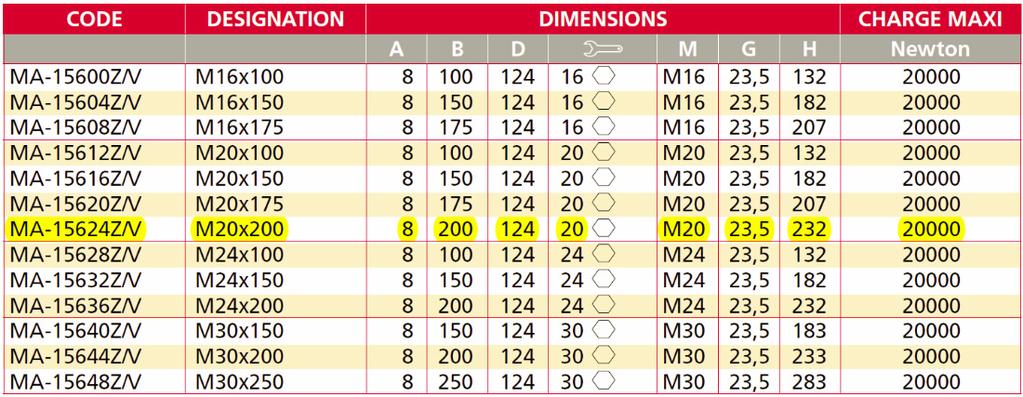
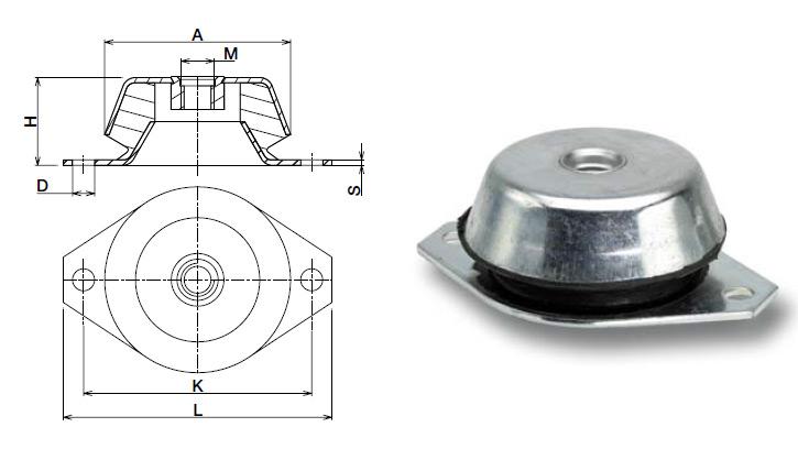
7 Use of supports for the conveyor units The support components: Where the conveyors are fixed to the ground, they rest on a supporting structure. This structure comprises two mounts, a cross beam and two adjustable pads. These have a C40 zinc-coated steel base and the base plate pad is made of vulcanised NBR rubber with a hardness of 80 shore.

8
9 Where conveyor units are suspended from the ceiling or a structure, we adopt various mounting methods. Ceiling mounting can involve the use of hangers, a cross beam and anti-vibration studs. These components are arranged at a maximum distance of 2 m. This is identical to the previous principle, but here a lateral maintenance gangway is attached which can withstand a maximum load of 250 kg per m2. Different methods of bracing the hangers are illustrated here to increase rigidity.
10
JEEVES. JEEVES Installation Manual. Installation Manual The Easiest Do-It-Yourself Dumbwaiter on the Market
 1 888-323-8755 www.nwlifts.com JEEVES Installation Manual The Easiest Do-It-Yourself Dumbwaiter on the Market This manual will cover the installation procedure step-by-step. The installation of this dumbwaiter
Saxton. Steel Sectional Doors
 Saxton Steel Sectional Doors Saxton sectional doors are a custom designed door ideal for most commercial and light industrial applications such as workshops, warehouses and small car parks. Encompassing
600 SERIES STANDARD DUTY STRAIGHT TRACK INSTALLATION INSTRUCTIONS
 600 SERIES STANDARD DUTY STRAIGHT TRACK INSTALLATION INSTRUCTIONS PLEASE READ INSTRUCTIONS THOROUGHLY BEFORE BEGINNING. A. BI-PARTING TRAVEL 1. Before raising track into position, determine location of
<THESE INSTRUCTIONS MUST BE GIVEN TO THE END USER> B&W
 B&W Trailer Hitches 6 Hawaii Rd / PO Box 86 Humboldt, KS 66748 P:60.473664 F:60.869.903 Turnoverball Gooseneck Hitch Installation Instructions MODEL 08
Austin. Aluminium Sectional Doors
 Austin Aluminium Sectional Doors The Austin aluminium sectional door has an elegant and timeless design ideal for contemporary style homes and commercial applications such as showrooms, workshops or small
SECTION CENTRIFUGAL HVAC FANS
 SECTION 233416 - CENTRIFUGAL HVAC FANS 1. PART 1 GENERAL 1.1. RELATED DOCUMENTS A. Drawings and general provisions of the Contract, including General and Supplementary Conditions and Division 01 Specification
Reflection. Aluminium Sectional Doors
 Reflection Aluminium Sectional Doors The Reflection aluminium sectional door features a chic round edge aluminium extrusion that can be clad with either glass or acrylic. Featuring a strong, sleek and
01 09 Installation guidelines Air suspension units GL70 GL70HD GL70L GN Air suspension units GL70 GL70HD GL70L
 01 09 Installation guidelines Air suspension units GL70 GL70HD GL70L GN0031-1 Air suspension units GL70 GL70HD GL70L can be identified by the hanger brackets with a welded-on support for the eccentric
SECTION HVAC POWER VENTILATORS
 SECTION 233423 HVAC POWER VENTILATORS 1. PART 1 GENERAL 1.1. RELATED DOCUMENTS A. Drawings and general provisions of the Contract, including General and Supplementary Conditions and Division 01 Specification
Baggage Handling Conveyors
 Baggage Handling s Geo. Robson & Co. Airport Baggage Mechanical Handling Solutions offer the ultimate for speed, reliability, robustness and product life. With a range of conveying solutions to suit the
SECTION AXIAL HVAC FANS
 SECTION 233413 - AXIAL HVAC FANS 1. PART 1 GENERAL 1.1. RELATED DOCUMENTS A. Drawings and general provisions of the Contract, including General and Supplementary Conditions and Division 01 Specification
RIG-I-FLEX 140 SERIES CURTAIN TRACKS
 RIG-I-FLEX 140 SERIES CURTAIN TRACKS Parts Included 140 RIG-I-FLEX CWANA code CORD OPERATED/MOTORIZED WALK-ALONG 140 (240) 140-R (240-R) 141 (241) 141-R (241-R) 142 (242) 142-R (242-R) STRAIGHT CURVED
Apron Feeders. TEREX JAQUES APRON FEEDERS Capacities up to 14,500 tph Proven design based on crawler tractor components Custom designed for the duty
 Apron Feeders TEREX JAQUES APRON FEEDERS Capacities up to 14,500 tph Proven design based on crawler tractor components Custom designed for the duty Apron Feeders Terex Jaques Apron Feeders use heavy-duty
300 SERIES STANDARD DUTY CURVED TRACK
 300 SERIES STANDARD DUTY CURVED TRACK COMPLETE TRACK MODEL NUMBERS 301A 301W 316A 316W 328A 328W 300B SERIES BLACK CURVED TRACK COMPLETE TRACK MODEL NUMBERS 301AB 301WB 316AB 316WB 328AB 328WB SINGLE CARRIER
Belt Driven. Conveyors (989) Roller Conveyors Belt Driven Live. Roller Conveyors
 Roller Conveyors Belt Driven Live. Roller Conveyors") Belt Driven Live Conveyors Conveyors - 195 - Light Duty Transportation Type... 196 Minimum Pressure Accumulation Type... 198 Medium Duty Transportation Type... 200 Heavy Duty Transportation Type... 202
Belt Driven Live Conveyors Conveyors - 195 - Light Duty Transportation Type... 196 Minimum Pressure Accumulation Type... 198 Medium Duty Transportation Type... 200 Heavy Duty Transportation Type... 202
Spring hangers, spring supports
 Spring hangers, spring supports 2 spring Spring hangers, supports PRODUCT 2 GROUP Spring hangers, spring supports Contents Page Field of application...2.1 Overview of spring hangers and spring supports...2.3
High-Rise Tire Dolly
 High-Rise Tire Dolly Assembly & Operation Instructions Model 70131 Capacity 1000 lb SAVE THESE INSTRUCTIONS. For your safety and the safety of others around you, read carefully before attempting to install,
Roller chain idler sprocket units Idler pulley units
 Roller chain idler sprocket units Idler pulley units Roller chain idler sprocket units, idler pulley units Page Product overview Roller chain idler sprocket units, idler pulley units... 334 Design and
MC2 BOWLING Pin-Setter
 MC2 BOWLING Pin-Setter File No.: M200509-01 COPYRIGHT 2005, VIA BOWLING PRODUCTS Content I. Installation of Front-End Assembly --------------------------------------- 1 II. Installation of Back-End Assembly
Signature Overhead System INSTALLATION MANUAL
 Signature Overhead System TM INSTALLATION MANUAL PACLINE Installation Manual Read All Instructions Carefully Proper installation is not difficult, and by adhering to the following procedures the conveyor
A1062 & A1072 AUGER ASSEMBLY MANUAL. Read & understand all instructions pertaining to this auger prior to use!
 A1062 & A1072 AUGER ASSEMBLY MANUAL Read & understand all instructions pertaining to this auger prior to use! Safety Alert Watch for this ALERT Symbol. It identifies potential hazards to Personal SAFETY
160S Rewind Option Kit Installation Instructions
 Installation Instructions GENERAL This kit includes the parts and documentation necessary to install the Media Rewind Option into the Zebra 160S printer. Read these instructions thoroughly before attempting
READ ALL INSTRUCTIONS THOROUGHLY PRIOR TO INSTALLATION
 Conveyor Idler Installation and Operation Manual Short Term Storage If conveyor idlers are to be stored for an short period(less than 3 months) prior to installation, the following steps should be taken.
Section Content. Straight Curve Optional Equipment and Devices
 Chain Driven Live Roller Conveyor Section Content Straight Curve Optional Equipment and Devices 31 CDLR Chain DRIVEN LIVE ROLLER CONVEYOR Why CDLR? Roller size and centers optimized to handle nearly any
The revamping and upgrading of Trinecke Zelezarny wire rod mill-czech Republic
 DANIELI MORGÅRDSHAMMAR The revamping and upgrading of Trinecke Zelezarny wire rod mill-czech Republic Choice of advanced equipment technology merged with Danieli s long lasting experience in upgrading
INSTALLATION, MAINTENANCE, & SAFETY INSTRUCTIONS
 Tarpaulin Systems Flip -N- Go / Quick Mount Flip -N- Go System INSTALLATION, MAINTENANCE, & SAFETY INSTRUCTIONS (800) CRAMARO (800) 272-6276 Plants In: Delaware, Florida, Massachusetts, Nevada, Ohio Install
BEARINGS The lower bearing assemble is constructed to allow continuous operation when fully submerged in wastewater.
 GENERAL SPECIFICATION INTENT The equipment to be supplied by manufacturer includes the screw pumps, support for the drive unit, profile plates, motors, gearboxes, couplings, guards, upper and lower bearing
The GK units differ from the LK units in that the springs of the GK units have a spring eye at the front.
 01 09 Installation guidelines Mechanical suspension units GK LK GN0032-0 Mechanical suspension units GK LK The GK units differ from the LK units in that the springs of the GK units have a spring eye at
TECHNICAL DATA BROCHURE - ZTR 424 & 427 DATE 8/85 PAGE 1 OF 8
 TECHNICAL DATA BROCHURE - ZTR 424 & 427 DATE 8/85 PAGE 1 OF 8 IMPORTANT - READ OPERATOR'S MANUAL BEFORE OPERATION OR MAKING ADJUSTMENTS Deluxe Seat Adjustment Easy hand lever action allows forward and
Timber Sectional Doors
 are available in a wide variety of sophisticated panel designs and finishes and provide a warm, cozy and welcoming impression. Typically manufactured from Western Red Cedar, these quality doors can truly
 DRUM BRAKE RIMS Periodic inspection of drum brake rims is necessary to determine indications of uneven or excessive wear. In general, brake rim failures other that regular wear are caused by brake linings
SCdefault. 900 Installation instructions
 SCdefault 900 Installation instructions SITdefault Sports chassis MONTERINGSANVISNING INSTALLATION INSTRUCTIONS MONTAGEANLEITUNG INSTRUCTIONS DE MONTAGE Accessories Part No. Group Date Instruction Part
TECHNICAL DATA BROCHURE ZTR 308/3II
 Date 8/84 Page 1 of 6 TECHNICAL DATA BROCHURE ZTR 308/3II IMPORTANT - READ OPERATOR'S MANUAL BEFORE OPERATION OR MAKING ADJUSTMENTS. ' Seat Adjustment Loosen bolts on sliding brackets under each side of
B.I. Brooks and Sons Inc. Overhead Conveyor
 B.I. Brooks and Sons Inc. Overhead Conveyor 3 and 4 I-Beam Conveyor Components X348 and X458 Track, Chain, and Trolleys Roller Turns and Traction Wheel Turns Drive Units Chain Take Ups in business since
<THESE INSTRUCTIONS MUST BE GIVEN TO THE END USER> B&W
 B&W Trailer Hitches 1216 Hawaii Rd / PO Box 186 Humboldt, KS 66748 P:620.473.3664 F:620.869.9031 Turnoverball Gooseneck Hitch Installation Instructions
Model 104 Slider Belt Conveyor
 Model 104 Slider Belt Conveyor Model Description: The Model 104 Slider Bed Belt is designed with the systems approach in mind. The square head and tail end terminals allow you the flexibility to combine
9000 Series Uni-Belt Technical Specifications
 Design Elements: The 9000 Series Uni-Belt conveyor is designed and engineered to meet specific requirements for load, unload, and transport needs of the baggage handling industry. Rugged and versatile,
Part # GM F Body Rear R-Joint Bolt-in 4 Link GM F Body Rear Bolt-in 4Link. Table of contents. Installation Instructions
 Part # 11167199-1967-1969 GM F Body Rear R-Joint Bolt-in 4 Link Recommended Tools 1967-1969 GM F Body Rear Bolt-in 4Link Installation Table of contents Page 2-3... Included Components Page 4... Hardware
SPARE PARTS LIST RIDERS R322T AWD, , , ,
 SPARE PARTS LIST RIDERS R322T AWD, 966785801, 967032101, 967153001, 2012-03 103CM CUTTING DECK R322T AWD, 966785801, 967032101, 967153001, 2012-03 103CM CUTTING DECK R322T AWD, 966785801, 967032101, 967153001,
BESTEEL Model 170 Curtain Tracks BESTEEL Model 171-N Curtain Tracks BESTEEL Model 171-R Curtain Tracks
 BESTEEL Model 170 Curtain Tracks - Curtain tracks shall be of 14 gauge galvanized steel construction entirely enclosed except for slot in bottom, each half to be in one continuous piece except where splicing
OPERATION AND MAINTENANCE INSTRUCTIONS
 OPERATION AND MAINTENANCE INSTRUCTIONS 334 SERIES THREE-PIECE BALL VALVES 1/4 to 2-1/2 Installation and Operation Always install your valve according to accepted industry standards and practices and operate
INSTALLATION AND MAINTENANCE MANUAL BELT CONVEYOR MODEL BS100B
 INSTALLATION AND MAINTENANCE MANUAL BELT CONVEYOR MODEL BS100B Version 2014.1 - - TABLE OF CONTENTS INTRODUCTION Receiving, Inspection and Uncrating... 3 Ordering Replacement Parts... 3 SAFETY INFORMATION
PRECISMECA - MONTAN Gesellschaft für Fördertechnik mbh. Documentation Operating Instructions. Rollers
 PRECISMECA - Gesellschaft für Fördertechnik mbh Documentation Operating Instructions Rollers Operating Instructions Index No.: T311-00 Page: 1 of 1 Section Document No. Pages Preface Safety Technical data
62 Deck Idler Kit High Speed
 Part No. 00 FORM NO. -899 6 Deck Idler Kit High Speed For Model 70 Serial No. 99000 to 99000 For Model 7 Serial No. 9900 to 99000 INSTALLATION INSTRUCTIONS Loose Parts Note: Use the chart below to identify
Pin-guided clutch with three flyweights
 S-Type Pin-guided clutch with three flyweights Construction and mode of operation 2 5 4 3 3 1 1 5 2 6 4 = Hub = Flyweights = Cylindrical pin = Tension spring = Lining = Clutch drum / Cover disc Low noise
READ THESE INSTRUCTIONS CAREFULLY BEFORE STARTING INSTALLATION FIGURE 1 INSTALLATION
 READ THESE INSTRUCTIONS CAREFULLY BEFORE STARTING INSTALLATION OPERATION & MAINTENANCE PRO TRAINER The Pro Trainer is designed to correct lateral belt misalignment by providing a positive steering force
Specialties Inc. DISCLAIMER TABLE OF CONTENTS
 TABLE OF CONTENTS Curtain Track Selection Guide...2 Ordering COMPLETE Tracks...3 Recommended Track Hanger Spacing...4 100 Series Standard-Duty Straight Track...6 200 Series Black Medium-Duty Straight Track...10
Continuous mechanical handling equipment - Safety code for belt conveyors - Examples for guarding of nip points
 TECHNICAL REPORT 5045 Published 1979-04-01 IS0 Technical Reports are subject to review within three years of publication, with the aim of achieving the agreements necessary for the publication of an International
An Investment in Plant Floor Safety. 802C Safety Cable Pull Switches 802E Hinge Safety Interlock Switches 802F Safety Interlock Switches
 An Investment in Plant Floor Safety 802C Safety Cable Pull Switches 802E Hinge Safety Interlock Switches 802F Safety Interlock Switches Notes 2 802C Cable Pull Safety Switches Safety and Application Safety
Belt Conveyors GUF-P MINI
 Belt Conveyors GUF-P MINI Conveyor frame profiles mk 2075 mk 2100 mk 2150 22 The minimal install height, as well as the lower walls for direct placement of the conveyor on the machine bed, are ideal for
Service Manual. Bolens 683 Series Box Frame Tractor IMPORTANT: READ SAFETY RULES AND INSTRUCTIONS CAREFULLY
 Service Manual Bolens 683 Series Box Frame Tractor IMPORTANT: READ SAFETY RULES AND INSTRUCTIONS CAREFULLY This Service Manual is not a substitute for the Operator s Manual. You must read, understand and
Marine Engineering Exam Resource Review of Couplings
 1. What are rigid couplings used for? Used to join drive shafts together. True alignment and rigidity are required. Example Drive shafts and production lines, bridge cranes, solid shaft that needs to be
Belt Conveyor Systems
 Belt Conveyor Systems Product & Installation Manual 24-in, 36-in, and 48-in Widths Manual #: IM-704-01 i 11/14 ii Table of Contents SECTION 1 OVERVIEW 1-1 System Length 1-1 Component Dimensions 1-2 Drive
TAKE TIME TO READ THE INSTALLATION PROCEDURES BEFORE STARTING
 INSTALLATION INSTRUCTIONS for TTi Small Block Header Part No.: TTI340BE17835 TAKE TIME TO READ THE INSTALLATION PROCEDURES BEFORE STARTING WARNING!!! We strongly suggest that you use an old set of headers
Part # GM F Body Complete CoilOver System
 350 S. St. Charles St. Jasper, In. 47546 Ph. 812.482.2932 Fax 812.634.6632 www.ridetech.com Part # 11170109 70-81 GM F Body Complete CoilOver System Front Components: 1 11173509 Front Fixed Valving CoilOvers
Table of Contents QUICK REFERENCE GUIDE FOR 42K17Z...A - 1 DECK COMPONENTS... B - 1 DECK LIFT COMPONENTS... C - 1 FRAME COMPONENTS...
 4 2 K 1 Z PARTS MANUAL Table of Contents QUICK REFERENCE GUIDE FOR 42K1Z...A - 1 DECK COMPONENTS... B - 1 DECK LIFT COMPONENTS... C - 1 FRAME COMPONENTS... D - 1 DRIVE COMPONENTS... E - 1 CONTROL COMPONENTS
TOP 10 NOISE CONTROL TECHNIQUES
 TOP 10 NOISE CONTROL TECHNIQUES The following are 10 simple noise control techniques that have wide application across the whole of industry. In many cases, they will produce substantial noise reductions
INSTALLATION AND MAINTENANCE MANUAL TROUGH BELT CONVEYOR MODEL TBOH
 INSTALLATION AND MAINTENANCE MANUAL TROUGH BELT CONVEYOR MODEL TBOH Version 2014.1 - - TABLE OF CONTENTS INTRODUCTION Receiving, Inspection and Uncrating... 3 Ordering Replacement Parts... 3 SAFETY INFORMATION
SIDEWINDER 350 INSTALLATION INSTRUCTIONS & OPERATION MANUAL NOVEMBER 2011
 SIDEWINDER 350 INSTALLATION INSTRUCTIONS & OPERATION MANUAL NOVEMBER 2011 PATENT PENDING Donovan Enterprises 3353 SE Gran Park Way, Stuart FL 34997 800-327-8287 www.donovan-ent.com PACKING LIST FOR SIDEWINDER
Cross Tensioners. Frames. Bearings. Springs. Mounting Holes. Adjustment Marks
 Cross Tensioners Cross Tensioners provide constant belt or chain tension. Their automatic tensioning action translates into improved performance and extended life for most types of fixed-centre drives.
INSTALLATION INSTRUCTIONS
 INSTALLATION INSTRUCTIONS REAR DRUM TO DISC BRAKE CONVERSION KIT A130 JEEP CJ SERIES W/AMC-20 REAR AXLES AND 5 x 5-1/2" BOLT CIRCLE Thank you for choosing STAINLESS STEEL BRAKES CORPORATION for your braking
Ground Fault Cable Retractor GR1000L Service Manual
 AERO-MOTIVE COMPANY A Woodhead Industries, Inc. Subsidiary Ground Fault Cable Retractor GR1000L Service Manual IMPORTANT SAFETY INSTRUCTIONS Please read this manual carefully and follow its instructions.
400 SERIES STANDARD DUTY STRAIGHT TRACK INSTALLATION INSTRUCTIONS
 400 SERIES STANDARD DUTY STRAIGHT TRACK INSTALLATION INSTRUCTIONS PLEASE READ INSTRUCTIONS THOROUGHLY BEFORE BEGINNING. A. BI-PARTING TRAVEL BATTEN INSTALLATION 1. Place track either on the floor or on
INSTALLATION AND MAINTENANCE MANUAL ROLLER BED BELT CONVEYOR MODEL BR100C & BRI
 INSTALLATION AND MAINTENANCE MANUAL ROLLER BED BELT CONVEYOR MODEL BR100C & BRI Version 2014.1 - - TABLE OF CONTENTS INTRODUCTION Receiving, Inspection and Uncrating... 3 Ordering Replacement Parts...
BESTEEL 170 SERIES CURTAIN TRACKS
 BESTEEL 170 SERIES CURTAIN TRACKS BL = Black Finish 2XX Series Track Systems have a black finish. Parts Included 170 (270) 170 BESTEEL CWANA code CORD OPERATED/MOTORIZED 171 (271) 171-R (271-R) 260 172
PFadvantage Metalfor Araus 1360
 Metalfor Araus 1360 Note: Indented items indicate parts included in an assembly listed above Part Name/Description Part Number Quantity Instruction Kit Metalfor Araus 2005300-14 1 Display Bracket 4000134
Contents. Page. 1. Product description. 2. The AXC line of linear axes. 3. AXLT line of linear tables. AXC and AXS product overview...
 SNR Industry Contents Page 3 1. Product description AXC and AXS product overview... 6-8 Dynamic load ratings of the linear motion systems... 9 Compact modules... 10-11 Linear tables... 12 Telescopic axes...
technical sheet SECALT building maintenance units (BMU) MUSTANG models Mu215 and Mu318 ref.: T-688 rev. no.: 0 date: 04/2003 page: 1/7
 MUSTANG models Mu215 and Mu318 ref.: T-688 rev. no.: 0 date: 04/2003 page: 1/7") page: 1/7 1. DESCRIPTION The MUSTANG model Building Maintenance Unit (BMU) is a simple and economic system for all cleaning and maintenance on buildings. The cradle is designed to take two people together
page: 1/7 1. DESCRIPTION The MUSTANG model Building Maintenance Unit (BMU) is a simple and economic system for all cleaning and maintenance on buildings. The cradle is designed to take two people together
TECHNICAL DATA BROCHURE ZTR 426
 TECHNICAL DATA BROCHURE ZTR 426 Date 8/84 IMPORTANT - READ OPERATOR'S MANUAL BEFORE OPERATION. Page 1 of 6 Seat Adjustment Loosen bolts on sliding bracket under each side of seat, slide seat forward or
A B C D E F. b.tools Required (supplied by others) 3/16" Drill Bit 3/8" Wrench Phillips Head Screwdriver
 3/16 Drill Bit 3/8 Wrench Phillips Head Screwdriver") Page 1 of 13 5E.1 Parts List a. Below Deck Automatic Retractable Security Cover Kit (1) Tube End Bearing Plate (A) (1) Rope Reel with Motor Attached (B) (1) Rope Reel Cover (C) (1) Cover Drum (1) Cover
Page 1 of 13 5E.1 Parts List a. Below Deck Automatic Retractable Security Cover Kit (1) Tube End Bearing Plate (A) (1) Rope Reel with Motor Attached (B) (1) Rope Reel Cover (C) (1) Cover Drum (1) Cover
O SL. BPW Original spare parts Air suspensions series O / SL / AL BPW BERGISCHE ACHSEN BPW ORIGINAL SPARE PARTS. BPW Original spare parts
 BPW riginal spare parts Air suspensions // BPW BERGISCHE ACHSEN BPW riginal spare parts Air suspensions series / / BPW RIGIN SPARE PARTS BPW riginal spare parts Air suspensions Contents Page Air suspension
Minimising Bump Steer in the TR
 Minimising Bump Steer in the TR Bump Steer is when your wheels steer themselves without input from the steering wheel. The undesirable steering is caused by bumps in the road interacting with improper
Conveyor Solutions. Trellex FLEXOPIPE
 EN Trellex FLEXOPIPE 2 Trellex FLEXOPIPE flexible, unique, ecological! Conveyor belt systems of enclosed material transport are an excellent solution to various conveying problems. Metso is Europe s leading
A B C D E F. Tools Required (supplied by others)
") Page 1 of 17 Parts List Below Deck Automatic Retractable Security Cover Kit (1) Tube End Bearing Plate (A) (1) Rope Reel and Cover Drum Motor Assembly (B) (1) Cover Drum (1) Pulley Support Channel (2)
Page 1 of 17 Parts List Below Deck Automatic Retractable Security Cover Kit (1) Tube End Bearing Plate (A) (1) Rope Reel and Cover Drum Motor Assembly (B) (1) Cover Drum (1) Pulley Support Channel (2)
2 YEAR WARRANTY HOSE REELS. reelmaster Series heavy duty, quality hose reel engineered to save space
 STANDARD CAPacity 1400 Series 1400 Series heavy duty, quality hose reel engineered to save space 1400 Series* Holds up to 40 of 1/2 Hose For 1/4, and 1/2 I.D. Hose Swivel inlet: 1/2 NPSM Low pressure 1/2
Southeast Crush & Screen LLC # Fax #
 Southeast Crush & Screen LLC #615-289-9890 Fax # 931-540-0048 www.secrushandscreen.com Transportation Dimensions 14375 [47'-2"] 4140 [13'-7"] Feeding Height 3400 [11'-2"] Transport Height 3330 [10'-11"]
TECHNICAL DESCRIPTION
 TRAILER, LIGHTWEIGHT, CARGO, 750 KG (HAULMARK), MC2 TECHNICAL DESCRIPTION This instruction is authorised for use by command of the Chief of Army. It provides direction, mandatory controls and procedures
CALIFORNIA TRIMMER MOWER MAINTENANCE MANUAL
 CALIFORNIA TRIMMER MOWER MAINTENANCE MANUAL 2 Table of Contents Section 1: General Information Page Handle Assembly Instructions 4 Maintenance All Models 6 Oil Change Procedures All Models 9 Height Adjustment
A. This Section includes the following types of sectional overhead doors:
 SECTION 08361 - SECTIONAL OVERHEAD DOORS PART 1 - GENERAL 1.1 RELATED DOCUMENTS A. Drawings and general provisions of the Contract, including General and Supplementary Conditions and Division 1 Specification
SPARE PARTS LIST RIDERS R220T, , , ,
 SPARE PARTS LIST RIDERS R220T, 966785701, 967032001, 967150901, 103CM CUTTING DECK R220T, 966785701, 967032001, 967150901, 103CM CUTTING DECK R220T, 966785701, 967032001, 967150901, Ref Part no. Description
ACI Hoist & Crane. Festoon System. 689 S.W. 7th Terrace Dania, FL (954) Fax (954) Toll Free A-HOIST ( )
 Fax (954) Toll Free A-HOIST ( )") ACI Hoist & Crane Festoon System 689 S.W. 7th Terrace Dania, FL 33004 (954) 921-1171 Fax (954) 921-7117 Toll Free 1-888-4-A-HOIST (1-888-424-6478) www.acihoist.com 2 Standard Duty C-Track Index 1. General
ACI Hoist & Crane Festoon System 689 S.W. 7th Terrace Dania, FL 33004 (954) 921-1171 Fax (954) 921-7117 Toll Free 1-888-4-A-HOIST (1-888-424-6478) www.acihoist.com 2 Standard Duty C-Track Index 1. General
HSpecialties Inc. TABLE OF CONTENTS
 TABLE OF CONTENTS Introduction... Curtain Track Selection Guide...2 Ordering COMPLETE Tracks...3 00 Series Standard-Duty Straight Track...4 200 Series Black Medium-Duty Straight Track...8 300 Series Standard-Duty
BPW Trailer axle HZF ECO Plus
 BPW Trailer axle HZF 900-5 ECO Plus L ( form closure ( square ) ) Brake SN 428 for ABS, with sensors Track 840 mm, Spring centre 950 mm, Booster bracket centre 4 mm for diaphragm cylinder, AGS ECO-Master,
COMPETITION ENGINEERING. 80 Carter Drive P.O. Box 1470 Guilford, CT Phone: (203) Fax: (203)
 Fax: (203)") INSTALLATION INSTRUCTIONS P/N S: C2090 & C2092 SLIDE-A-LINK The Slide-A-Link by Competition Engineering is designed for use in Stock Eliminator and Bracket Racing vehicles. The rigid front mount assembly
INSTALLATION INSTRUCTIONS P/N S: C2090 & C2092 SLIDE-A-LINK The Slide-A-Link by Competition Engineering is designed for use in Stock Eliminator and Bracket Racing vehicles. The rigid front mount assembly
Installation Instructions Table of Contents
 Installation Instructions Table of Contents Pre- Installation of Garage Storage Lift 2 Layout the Garage Storage Lift 3 Installing the strut Channels 3 Install the Drive Assembly 5 Install the Drive Shaft
INSTRUCTION MANUAL 16K - Fifth Wheel Hitch
 You can take it with you. INSTRUCTION MANUAL 16K - Fifth Wheel Hitch Product No. 30047 DEALER/INSTALLER: END USER: (1) Provide this Manual to end user. (2) Physically demonstrate hitching and unhitching
SLIDE DOOR OPERATOR ADDENDUM
 SLIDE DOOR OPERATOR MODELS SD & GSD ADDENDUM 2 YEAR W ARRANTY Serial # (located on electrical box cover) NOT FOR RESIDENTIAL USE 1B6 Installation Date Wiring Type LISTED DOOR OPERATOR SPECIFICATIONS Adjustable
Sub Section Title Page No.
 Sub Section Title Page No. 1 Introduction 3 2 Routine Maintenance 3 3 Disassembly 4 3.1 Disassembly of Double Crank Design 4 3.2 Disassembly of Scotch Yoke Design 5 3.3 Disassembly of Actuator Cylinder
Installation Instructions February 2009
 Installation Instructions February 2009 www.donovan-ent.com Donovan Enterprises 3353 SE Gran Park Way Stuart, FL 34997 800-327-8287 The Hammer Head Assembly Installation Instructions (Rollerbar & Direct
Premium Dry Freight (Plywood) Door Installation REFERENCE FIGURE 1
 Door Installation REFERENCE FIGURE 1") Premium Dry Freight (Plywood) Door Installation A Premium door can be identified as usually having a two-spring balancer, 2 diameter (nominal) rollers, and end hinges with removable covers. If your Whiting
Premium Dry Freight (Plywood) Door Installation A Premium door can be identified as usually having a two-spring balancer, 2 diameter (nominal) rollers, and end hinges with removable covers. If your Whiting
Manipulators. Basic/Background Info Types of Manipulators General Manipulator design tips
 FTC Manipulators By: Zach Zakfeld (Enigma Robotics) Teams: FTC 5391, FTC 5385 and FRC 2075 *Some images in this presentation are of FRC robots so exact designs may not be applicable, however all of the
accqpulse Velocity Profiler Sensor Installation Guide
 accqpulse Velocity Profiler Sensor Installation Guide Instruction Sheet #69-7403-012 Released May 2016 Overview This instruction guide is for the installation of the accqpulse shallow water and deep water
Installation Instructions LamboStyleDoors (The instruction are to be used as a reference. Please repeat for both doors)
") Installation Instructions LamboStyleDoors (The instruction are to be used as a reference. Please repeat for both doors) Mercedes C-Class Sport coupé type W203 Part number 500 25 009 Pre installation check
Installation Instructions LamboStyleDoors (The instruction are to be used as a reference. Please repeat for both doors) Mercedes C-Class Sport coupé type W203 Part number 500 25 009 Pre installation check
LKS300/LKS450 OPERATOR S MANUAL
 LKS300/LKS450 OPERATOR S MANUAL SAFETY RULES SHIFTA 300/450 Conveyor DANGER Failure to obey the instructions and safety rules in this manual will result in death or serious injury. Do Not Operate Unless:
ECO Plus 2 - The new generation of the proven BPW ECO Unit
 BPW-NEWS Allg 7125703e BPW NEWS BPW BERGISCHE ACHSEN ECO Plus 2 - The new generation of the proven BPW ECO Unit The BPW ECO Unit has proven itself millions of time over, and its ECO Plus version will be
argco.com
 800-854-1015 argco.com STRUT SUPORT SYSTEM STRUT SUPPORT CHANNEL US Strut Support Channel Quick, strong attachment of single or multiple pipes horizontally or vertically Unlimited applications - range
733:1983 Specification for Wrought aluminium and aluminium alloy Bars, rods and sections (for general engineering purposes) (third revision)
 (third revision)") For comments only Doc:TED 17(721)W June 2009 Draft Indian Standard ALUMINIUM SHORE GANGWAYS SPECIFICATION (First Revision of IS 10558) Not to be reproduced without permission Last date for receipt of BIS
For comments only Doc:TED 17(721)W June 2009 Draft Indian Standard ALUMINIUM SHORE GANGWAYS SPECIFICATION (First Revision of IS 10558) Not to be reproduced without permission Last date for receipt of BIS
OPERATIONS MANUAL LEVER CHAIN HOIST
 OPERATIONS MANUAL LEVER CHAIN HOIST IMPORTANT SAFETY INFORMATION Please read, understand and follow all safety information contained in these instructions prior to the use of this hoist. Retain these instructions
Self-Adjusting Clutch (SAC) Technology Special tools / User instructions
 Technology Special tools / User instructions") Self-Adjusting Clutch (SAC) Technology Special tools / User instructions The content of this brochure shall not be legally binding and is for information purposes only. To the extent legally permissible,
Self-Adjusting Clutch (SAC) Technology Special tools / User instructions The content of this brochure shall not be legally binding and is for information purposes only. To the extent legally permissible,
INSTALLATION INSTRUCTIONS
 INSTALLATION INSTRUCTIONS REAR DISC BRAKE CONVERSION KIT A126-1 1973-87 CHEVROLET 1/2 TON 2WD Thank you for choosing STAINLESS STEEL BRAKES CORPORATION for your braking needs. Pleases take the time to