Part # GM F Body Complete CoilOver System
|
|
|
- Beryl Morton
- 5 years ago
- Views:
Transcription
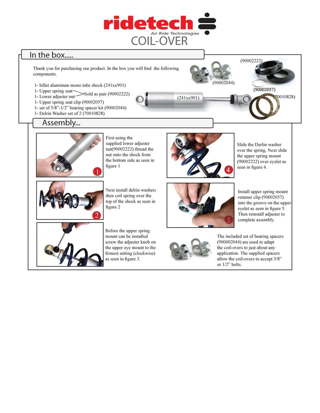
1 350 S. St. Charles St. Jasper, In Ph Fax Part # GM F Body Complete CoilOver System Front Components: Front Fixed Valving CoilOvers Front Lower StrongArms Front Upper StrongArms Rear Components: Rear AirBar Bolt-on 4 Link Rear Fixed Valving CoilOvers Components: Spanner Wrench
2 350 S. St. Charles St. Jasper, In Ph Fax Part # GM F Body Non Adjustable Front CoilOvers For Use w/ StrongArms Shock Assembly: stroke non adjustable shock non adjustable threaded stud top I.D. bearing Bearing snap ring Components: Coil spring 8 long / 600 # rate stud top base Spring retainer kit Aluminum cap for Delrin ball Delrin ball upper half Delrin ball lower half Delrin Spring Washer Hardware: /16 SAE Nylok jam nut Stud top hardware
 8. Screw 9.")
3 1. Impact Forged, Monotube shock 2. Rebound adjustment knob (SA Only) 3. Upper coil spring retainer 4. Lower coil spring retainer 5. High tensile coil spring 6. Set screw 7. Delrin Spring Washer 1. Stud top base 2. Lower Delrin ball half 3. Upper Delrin ball half 4. Aluminum cap 5. 9/16 Nylok jam nut 6. Threaded stud 7. Adjustment knob (SA Only) 8. Screw 9. Snap ring

4 1. To allow the step in the lower Delrin ball half to slide into the factory shock hole, the bushing cup will need to be removed (if your car has one) and the hole may need to be drilled out to ¾. 2. Assemble the CoilOver then place into the coil spring pocket w/ the stud and lower Delrin ball sticking through the factory shock hole. 3. Check clearance between the upper factory spring retaining lip and stud top base. Allowing this to hit could cause the shock to break, this 4. Place the upper Delrin ball over stud, then the aluminum cap. Secure the assembly w/ the 9/16 Nylok jam nut. 5. Attach the bottom of the shock to the lower StrongArms using the spacers and hardware supplied w/ the arm.
5 350 S. St. Charles St. Jasper, In Ph Fax Part # GM F Body Lower StrongArms For Use w/ Shockwaves or CoilOvers Components: Driver side arm Passenger side arm Ball joint (includes boot, grease fitting, castle nut & cotter pin) Polyurethane bushing half /2" I.D. Inner bushing sleeve installed in arms ( 70-72) /16 I.D. Inner bushing sleeve ( 73-81) Aluminum bearing spacer ¼-28 grease fitting Use Lithium grease in control arm bushings Hardware: /2"-13 x 3 ¼ Gr.5 bolt Shockwave to lower arm /2"-13 Nylok nut Shockwave to lower arm /8 x 5 ½ USS bolt Sway bar end link /8 Nylok nut Sway bar end link /2"-13 x 3 ½ Gr.5 bolt Lower arm to frame ( 71 & 72) /2"-13 Nylok Jam Nut Lower arm to frame ( 71 & 72) /16"-12 x 3 ½ Gr.5 bolt Lower arm to frame ( 73 & 81) /16"-12 Nylok Jam Nut Lower arm to frame ( 73 & 81)

6 Installation Instructions 1. After removing the factory lower control arm, clean the bushing mounting surfaces on the frame and lubricate with Lithium grease. 2. Fasten the lower arm to the frame with the hardware supplied. There are two different size bushing sleeves supplied 1/2" and 9/ & 72 model years will use 1/2" will use 9/16. Note: On some cars the frame brackets may be pinched and will need to be spread back apart to allow the bushing to slide in. 3. Swing the lower StrongArm up to the Shockwave or CoilOver and secure with the ½ x 3 ¼ bolt and Nylok nut, an aluminum spacer must be installed on each side of the bearing. 4. Slide the ball joint boot over the stud, then push the stud up through the spindle. Secure w/ the new castle nut and cotter pin supplied. 5. Grease the ball joints. 6. Lubricate lower arm bushings w/ Lithium grease. Driver Side
7 Item # Description Qty. 1. Passenger side arm 1 1. Driver side arm 1 2. Aluminum bearing spacer /2"-13 x 3 ¼ bolt /2-13 Nylok nut 6 5. Ball joint 8 6. Inner bushing sleeve 4 7. Poly bushing half /2-13 x 3 ½ bolt /2-13 Nylok nut 6
8 350 S. St. Charles St. Jasper, In Ph Fax Part # GM F Body Upper StrongArms Components: Driver side arm Passenger side arm Upper ball joint (includes boot, grease fitting, castle nut & cotter pin) Cross shaft kit w/ bushings & hardware (Install serrated washer between shaft and bushing) tall bump stop w/ hardware
 2.")
9 1. Fasten the upper arm to the frame using the factory hardware. Reinstall the current alignment shims, but vehicle must be realigned. This arm was designed with an extra 2 degrees of positive caster allowing the car to be aligned with up to 4 degrees of positive caster. (This will vary from car to car.) 2. Slide the bump stop stud through the 3/8 hole in the lower control arm. 3. Drop ball joint down through upper arm. Slide ball joint boot over stud, then place boot retainer over the boot. Clamp assembly tight w/ the hardware supplied. 4. Fasten the ball joint to the spindle w/ the new castle nut and cotter pin supplied. 5. Position the suspension at mid travel and then tighten the cross shaft nuts. Driver Side Top View
10 Item # Description Qty. 1. 1/4"-28 x 7/8 hex bolt /4"-28 nut 8 3. Driver side control arm 1 3. Passenger side control arm 1 4. Cross shaft 2 5. Serrated washer 4 6. Cross shaft bushing 4 7. Cone washer /8-18 locking nut 4 9. Ball joint 2
11 350 S. St. Charles St. Jasper, In Ph Fax Part # GM F Body AirBar For Use w/ Shockwaves or CoilOvers Components: Lower bar axle mount Driver side Lower bar axle mount Passenger side Driver side upper cradle assembly Passenger side upper cradle assembly Lower bar - WW Passenger side Lower bar - WW Driver side ¼ -28 straight grease fitting Upper bars - TW7.375 (C-C length ) Threaded Kevlar lined Heim end ¾ -16 jam nut for rod end Aluminum spacer for Heim end Rubber bushings pressed into bars Poly bushing half Front of lower bar Inner bushing sleeve Front of lower bar Lower billet Shockwave mount Lower Shockwave stud Aluminum spacer for stud Inner axle tabs (Short) Outer axle tabs (Long) Axle tab braces Upper cradle reinforcement plates Jig brackets for upper bar installation Hardware: Part # /16-20 Nylok nut Lower bar axle mount 8 7/16 SAE flat washer Lower bar axle mount 10 3/8-16 x 1 thread forming screw Upper cradle assembly 22 3/8 SAE flat washer Upper cradle assembly & reinforcement plates 12 3/8-16 Nylok nut U-bolts and reinforcement plates 2 3/8-16 x 3 square U-bolts Upper cradle assembly 2 1/2-13 x 1 ¼ Gr.5 bolt Billet mount to axle bracket 2 1/2"-13 x 1 ¾ Gr.5 bolt Billet mount to axle bracket 4 1/2-13 Nylok nut Billet mount to axle bracket 6 5/8-11 x 2 ¾ Gr.5 bolt Upper and lower bars 6 5/8-11 Nylok jam nut Upper and lower bars 2 1/2"-13 x 2 ¼ Gr.5 bolt Upper Shockwave mount 2 1/2"-13 Nylok jam nut Upper Shockwave mount 2 3/8-16 x ¾ Gr. 5 bolt Upper bar installation jig 2 3/8-16 nut Upper bar installation jig


12 1. Raise the vehicle to a safe and comfortable working height. Use jack stands to support the vehicle with the suspension hanging freely. 2. Support the axle and remove the leaf springs, shocks, tail pipes, bump stops and pinion snubber. Refer to the factory service manual for proper disassemble procedures. Keep the factory U-bolts and the front leaf spring mounts and bolts. They will be reused. 3. Fasten the large end of the lower bar to the factory leaf spring hanger using the factory hardware. Then reattach the hanger to the car. These two larger bushings are polyurethane and are lubricated at the factory. Future lubrication can be done with any non petroleum based lubricant such as lithium or silicone. The Bar is installed with it offset to the inside of the car for more wheel and tire clearance. 4. Bolt the lower bar axle mount to the leaf spring pad using the factory studs and U-bolt. The mount is offset to the inside to provide more tire clearance. New 7/16 Nyloc nuts are supplied. 5. Attach the Billet ShockWave mount to the axle mount using the ½ bolts and Nyloc nuts. It will be easiest to do this before attaching the lower bar. 6. Swing the small end of the lower bar up to the axle and secure with 5/8 x 2 ¾ bolt and Nyloc. Do not tighten yet.


13 7. Raise the upper cradle into position against the body and clamp in place. The contour of the plate will match the contour of the body. On cars that came with a factory sway bar the two forward holes on the bottom will already be there. The rest of the holes must be drilled with a 5/16 bit. Use the 3/8 x 1 thread forming bolts to secure the assembly. 8. Using the cradle as a template, drill four 3/8 holes in the floor pan. 9. From the inside of the car drop the reinforcement plates through these holes. Secure the assembly with 4 3/8 Nyloc nuts and flat washers. You may need to flatten part of the seam just above the top two holes.


14 10. Bolt the upper bar to the cradle using a 5/8 x 2 ¾ bolt and Nyloc nut. 11. Bolt the two axle tabs to the other side of the bar also using a 5/8 x 2 ¾. The shorter tab will go to the inside. Pinion angle, axle center, and ride height must all be set before welding the tabs to the axle. 12. To center the axle drop a plum off the quarter panel and measure into the axle. 13. Ride height is determined by measuring 14 ½ center-to-center on the Shockwave. 14. Setting pinion angle is described on the next page. 15. One trick to help maintain these settings is to tack weld a 4 ¾ spacer between the bump stop pad and the axle. 16. Once everything is doublechecked the tabs can be tack-welded into place. Then tack in the axle tab brace between the two tabs. 17. To avoid heating the rubber bushing, remove the upper bar. The tabs and brace can now be welded solid. Only weld 1 at a time and skip around to avoid warping the axle tube. 18. Reinstall the upper bar and snug all of the Nyloc nuts with the axle still at ride height. These bushings are rubber and do not require any lubrication.


15 How do you set the pinion angle? On a single-piece shaft you want to set it up where a line drawn through the center of the engine crankshaft or output shaft of the transmission and a line drawn through the center of the pinion are parallel to each other but not the same line. A simple way to do this is to place a digital angle finder or dial level on the front face of the lower engine pulley or harmonic balancer. This will give you a reading that is 90 degrees to the crank or output shaft unless you have real problems with your balancer. At the other end, you can place the same level or angle finder against the front face of the pinion yoke that is also at 90 degrees to the centerline. If you rotate the yoke up or down so both angles match, you have perfect alignment. Road testing will tell you if you have it right. If you accelerate and you get or increase a vibration, then the pinion yoke is too HIGH. Rotate it downward in small increments of a degree or two until the problem goes away. If you get or increase a vibration when decelerating, then the pinion yoke is too LOW. Rotate it upward to correct it.


16 19. Apply thread sealant to an elbow air fitting and screw it into the top of the Shockwave. 20. Screw the lower Shock stud into the billet mount. Bolt the Shockwave to the stud with the Nyloc nut. There should be one spacer on either side of the bearing. The top eyelet will bolt to the cradle using a ½ x 2 ¼ bolt and Nylok jam nut. 21. The 4 ½ spacer can now be removed. 22. The exhaust will have to be rerouted. 23. The factory rear sway bar will not work, but most aftermarket ones will. 22. Double check to make sure the air spring cannot rub on anything at any time. This will cause failure and is not warrantable.


17 Upper Bar Installation Jig This jig has been supplied to aid in the installation of the upper 4 link bar. It can be temporarily used to properly align, locate and weld the tabs onto the axle. It will also ensure that the mounting bolts are parallel to the ground. Follow the diagram below to set the jig to the same length as the upper bar, use the 3/8 x 3/4 bolt and nuts to set the length. Position the axle at ride height. Center the axle left to right between the quarter panels. Set pinion angle. Bolt one end of the jig to the cradle using a 5/8 x 2 ¾ bolt. Using another 5/8 x 2 ¾ bolt, fasten the axle tabs to the other end. The tabs must be bolted to the outside of the jig. Swing the bar down letting the tabs rest onto the axle. Trim the brackets as necessary to minimize the gap to be welded. Check pinion angle, ride height and axle center. Tack-weld the tabs in place. Remove jig and install upper bar. Repeat this process for the other side. Recheck pinion angle, ride height and axle center. (Sound familiar?) After the tabs have been tack welded on both sides, remove the upper bars to avoid melting the rubber bushings. Let the axle drop down for better access to the tabs. Lay 1 welds on the inside and outside of the tabs. Skip around from one side to the other to avoid overheating the tube. Item # Description 1. Upper bar 2. 3/4-16 jam nut 3. Heim end 4. Alignment jig 5. Aluminum spacer 6. 5/8-11 x 2 ¾ bolt 7. 3/8-16 nut 8. 3/8-16 x 3/4" bolt
18 350 S. St. Charles St. Jasper, In Ph Fax Should I weld my AirBar 4 link assembly in? Since we get this question quite often, it deserves a proper explanation. The AirBar has been designed for bolt-in installation. We have paid special attention to interfacing with key structural areas of each vehicle, fastening bracketry in at least two planes to properly distribute load paths, and to using appropriate fasteners that roll, rather than cut, threads into the vehicle structure. Having said that, you could potentially encounter a vehicle that has rust or collision damage in these areas. Or maybe you intend to consistently place the vehicle in severe racing applications with sticky racing slicks and high speed corners. In these cases it is perfectly acceptable to weld the AirBar components into your vehicle. Even in these severe cases we recommend that you install the entire AirBar assembly first [including the fasteners], and then use short 1 long tack welds to secure your installation. Remember that the vehicle structure metal is typically much thinner [ ] than the.188 thick AirBar brackets. If you burn through the vehicle sheet metal structure you may end up with an installation that is weaker than before you tried to weld it. The other reason to weld in your AirBar assembly is you simply want to. You re a welding kind of guy that s the way you ve always done it you have the skills and equipment to do it. In that case weld away with our blessing!
19 350 S. St. Charles St. Jasper, In Ph Fax Part # GM F Body Fixed Valving Rear Coil-Overs For use w/ AirBar Shock Assembly: Fixed Valving Threaded Shock Bearing Bearing Snap Ring Eyelet Components: Coil spring 12 long / 200 # rate Spring retainer kit Aluminum Spacer,.500 ID Delrin Spring Washer Ride Height We have designed most cars to have a ride height of about 2 lower than factory. To achieve the best ride quality & handling, the shock absorber needs to be at 40-60% overall travel when the car is at ride height. This will ensure that the shock will not bottom out or top out over even the largest bumps. Measuring the shock can be difficult, especially on some front suspensions. Measuring overall wheel travel is just as effective and can be much easier. Most cars will have 4-6 of overall wheel travel. One easy way to determine where you are at in wheel travel is to take a measurement from the fender lip (center of the wheel) to the ground. Then lift the car by the frame until the wheel is just touching the ground, re-measure. This will indicate how far you are from full extension of the shock. A minimum of 1.5 of extension travel (at the wheel) is needed to ensure that the shock does not top out. If you are more than 3 from full extension of the shock then you are in danger of bottoming out the shock absorber. Adjusting Spring Height When assembling the Coil-Over, screw the spring retainer tight up to the spring (0 preload). After entire weight of car is on the wheels, jounce the suspension and roll the car forward and backward to alleviate suspension bind. If the car is too high w/ 0 preload then a smaller rate spring is required. Although threading the spring retainer down would lower the car, this could allow the spring to fall out of its seat when lifting the car by the frame. If the car is too low w/ 0 preload, then preload can then be added by threading the spring retainer up to achieve ride height. On stroke shocks, up to 1.5 of preload is acceptable. On 5-7 stroke shocks, up to 2.5 of preload is acceptable. If more preload is needed to achieve ride height a stiffer spring rate is required. Too much preload may lead to coil bind, causing ride quality to suffer.
20
Part # Mustang Complete SA CoilOver Kit
 Front Components: 350 S. St. Charles St. Jasper, In. 47546 Ph. 812.482.2932 Fax 812.634.6632 www.ridetech.com Part # 12100210 67-70 Mustang Complete SA CoilOver Kit 1 12103510 Single Adjustable Front CoilOvers
Part # Mustang Complete CoilOver Kit
 Front Components: 1 12103509 Front CoilOvers 1 12102899 Lower StrongArms 1 12103699 Upper StrongArms 350 S. St. Charles St. Jasper, In. 47546 Ph. 812.482.2932 Fax 812.634.6632 www.ridetech.com Part # 12100109
Part # Mustang Rear AirBar
 350 S. St. Charles St. Jasper, In. 47546 Ph. 812.482.2932 Fax 812.634.6632 www.ridetech.com Part # 12087199 64-70 Mustang Rear AirBar Components: 1 90000513 Lower Shockwave mount 1 90000514 Lower Shockwave
Part # Galaxie Air Suspension System
 350 S. St. Charles St. Jasper, In. 47546 Ph. 812.482.2932 Fax 812.634.6632 www.ridetech.com Part # 12160298 60-64 Galaxie Air Suspension System Front Components: 1 12162401 Master Series Single Adjustable
350 S. St. Charles St. Jasper, In Ph Fax
 350 S. St. Charles St. Jasper, In. 47546 Ph. 812.482.2932 Fax 812.634.6632 www.ridetech.com Part # 11167197 67-69 GM F Body AirBar Components: 1 90000527 Upper cradle assembly 1 90002077 Lower axle bracket
Part # Chevy Level 2 CoilOver Suspension Package Two Piece Frame
 350 S. St. Charles St. Jasper, In. 47546 Ph. 812.482.2932 Fax 812.634.6632 www.ridetech.com Part # 11030210 55-57 Chevy Level 2 CoilOver Suspension Package Two Piece Frame Front Components: 1 11013510
Part # Mustang Level 2 Air Suspension System
 350 S. St. Charles St. Jasper, In. 47546 Ph. 812.482.2932 Fax 812.634.6632 www.ridetech.com Part # 12100299 67-70 Mustang Level 2 Air Suspension System Front Components: 1 12103001 Single Adjustable Series
Part # Mustang Complete NA CoilOver Kit
 Front Components: 350 S. St. Charles St. Jasper, In. 47546 Ph. 812.482.2932 Fax 812.634.6632 www.ridetech.com Part # 12090109 64-66 Mustang Complete NA CoilOver Kit 1 12093509 Non Adjustable Front CoilOvers
Part # Mustang Complete CoilOver Kit
 Front Components: Part # 12100109 67-70 Mustang Complete CoilOver Kit 1 12103509 Non Adjustable Front CoilOvers 1 12102899 Lower StrongArms 1 12103699 Upper StrongArms Rear Components: 1 12106509 Non Adjustable
Part # Mustang Complete HQ Series Coil-Over Kit
 350 S. St. Charles St. Jasper, In. 47546 Ph. 812.482.2932 Fax 812.634.6632 www.ridetech.com Front Components: Part # 12090210 64-66 Mustang Complete HQ Series Coil-Over Kit 1 12093509 HQ Series Front Coil-Overs
Part # Mustang Complete HQ Series Coil-Over Kit
 350 S. St. Charles St. Jasper, In. 47546 Ph. 812.482.2932 Fax 812.634.6632 www.ridetech.com Front Components: Part # 12090210 64-66 Mustang Complete HQ Series Coil-Over Kit 1 12093509 HQ Series Front Coil-Overs
Part # Impala Level 1 Complete Coil-Over System RQ Series
 350 S. St. Charles St. Jasper, In. 47546 Ph. 812.482.2932 Fax 812.634.6632 www.ridetech.com Part # 11290109 65-66 Impala Level 1 Complete Coil-Over System RQ Series Front Components: 1 11283509 RQ Series
Part # Mustang Coil-Over System
 350 S. St. Charles St. Jasper, In. 47546 Ph. 812.482.2932 Fax 812.634.6632 www.ridetech.com Front Components: 1 12093509 HQ Series Front Coil-Overs Part # 12090201 64-66 Mustang Coil-Over System 1 12099599
Part # Impala Fixed Valving Coil-Over Suspension Package
 350 S. St. Charles St. Jasper, In. 47546 Part # 11060109 59-64 Impala Fixed Valving Coil-Over Suspension Package Front Components: 1 11053509 RQ Series Front Coil-overs 1 11052899 Front Lower StrongArms
Part # Chevy Level 2 Air Suspension Package One Piece Frame
 350 S. St. Charles St. Jasper, In. 47546 Ph. 812.482.2932 Fax 812.634.6632 www.ridetech.com Part # 11020299 55-57 Chevy Level 2 Air Suspension Package One Piece Frame Front Components: 1 11013001 Master
Part # Cougar CoilOver System
 Front Components: 1 12103510 HQ Series Front CoilOvers 1 12102899 Lower StrongArms 1 12103699 Upper StrongArms 1 12109100 Front MuscleBar w/ PosiLinks 350 S. St. Charles St. Jasper, In. 47546 Ph. 812.482.2932
Part # GM X Body Complete CoilOver System
 350 S. St. Charles St. Jasper, In. 47546 Ph. 812.482.2932 Fax 812.634.6632 www.ridetech.com Part # 11260210 68-74 GM X Body Complete CoilOver System Front Components: 1 11263510 Front HQ Series CoilOvers
Part # GM F Body Complete CoilOver System
 350 S. St. Charles St. Jasper, In. 47546 Ph. 812.482.2932 Fax 812.634.6632 www.ridetech.com Part # 11160109 67-69 GM F Body Complete CoilOver System Front Components: 1 11163509 Front Non-adjustable CoilOvers
Part # Impala TQ CoilOver Suspension Package
 350 S. St. Charles St. Jasper, In. 47546 Ph. 812.482.2932 Fax 812.634.6632 www.ridetech.com Part # 11040311 58 Impala TQ CoilOver Suspension Package Front Components: 1 11053511 TQ Series Front Coilovers
Part # Chevy Level 3 Street Challenge Package One Piece Frame
 350 S. St. Charles St. Jasper, In. 47546 Ph. 812.482.2932 Fax 812.634.6632 www.ridetech.com Part # 11020399 55-57 Chevy Level 3 Street Challenge Package One Piece Frame Front Components: 1 11013011 TQ
Part # Impala Level 2 Complete Coil-Over System HQ Series
 350 S. St. Charles St. Jasper, In. 47546 Ph. 812.482.2932 Fax 812.634.6632 www.ridetech.com Part # 11290210 65-66 Impala Level 2 Complete Coil-Over System HQ Series Front Components: 1 11283509 Front HQ
Part # GM F Body Complete CoilOver System
 350 S. St. Charles St. Jasper, In. 47546 Ph. 812.482.2932 Fax 812.634.6632 www.ridetech.com Part # 11160210 67-69 GM F Body Complete CoilOver System Front Components: 1 11163510 Front HQ Series CoilOvers
Part # Mustang Level 1 Air Suspension System
 350 S. St. Charles St. Jasper, In. 47546 Ph. 812.482.2932 Fax 812.634.6632 www.ridetech.com Part # 12090199 66-66 Mustang Level 1 Air Suspension System Front Components: 1 12092409 NA Series Front Shock
Part # Chevy Level 3 Street Challenge Package Two Piece Frame
 350 S. St. Charles St. Jasper, In. 47546 Ph. 812.482.2932 Fax 812.634.6632 www.ridetech.com Part # 11030399 55-57 Chevy Level 3 Street Challenge Package Two Piece Frame Front Components: 1 11013002 Master
Part # Mustang Complete Level 2 Air Suspension Kit
 350 S. St. Charles St. Jasper, In. 47546 Ph. 812.482.2932 Fax 812.634.6632 www.ridetech.com Front Components: Part # 12090299 64-66 Mustang Complete Level 2 Air Suspension Kit 1 12093001 HQ Series Front
Part # Impala Air Suspension System
 350 S. St. Charles St. Jasper, In. 47546 Ph. 812.482.2932 Fax 812.634.6632 www.ridetech.com Part # 11040298 58 Impala Air Suspension System Front Components: 1 11053001 HQ Series Front Shockwaves 1 11052899
Part # GM F Body Rear R-Joint Bolt-in 4 Link GM F Body Rear Bolt-in 4Link. Table of contents. Installation Instructions
 Part # 11167199-1967-1969 GM F Body Rear R-Joint Bolt-in 4 Link Recommended Tools 1967-1969 GM F Body Rear Bolt-in 4Link Installation Table of contents Page 2-3... Included Components Page 4... Hardware
Installation Instructions
 Part # 12087199-1965-1970 Mustang Rear Bolt-in 4 Link Recommended Tools 1965-1970 Mustang Rear Bolt-in 4 Link Installation Table of contents Page 2... Included components Page 3... Hardware List and Getting
Part # Chevy Rear AirBar (One Piece Frame)
") 350 S. St. Charles St. Jasper, In. 47546 Ph. 812.482.2932 Fax 812.634.6632 www.ridetech.com Part # 11027199 55-57 Chevy Rear AirBar (One Piece Frame) Components: 1 90000160 Driver side lower axle bracket
350 S. St. Charles St. Jasper, In. 47546 Ph. 812.482.2932 Fax 812.634.6632 www.ridetech.com Part # 11027199 55-57 Chevy Rear AirBar (One Piece Frame) Components: 1 90000160 Driver side lower axle bracket
Part # GM G Body Rear CoilOver Kit Single Adjustable
 350 S. St. Charles St. Jasper, In. 47546 Ph. 812.482.2932 Fax 812.634.6632 www.ridetech.com Part # 11326110 78-88 GM G Body Rear CoilOver Kit Single Adjustable Shock Assembly: 2 24159999 5 stoke single
Part # Mustang Air Suspension System
 350 S. St. Charles St. Jasper, In. 47546 Ph. 812.482.2932 Fax 812.634.6632 www.ridetech.com Front Components: Part # 12090298 64-66 Mustang Air Suspension System 1 12093001 HQ Series Front Shockwaves 1
Part # Impala Air Suspension System
 350 S. St. Charles St. Jasper, In. 47546 Ph. 812.482.2932 Fax 812.634.6632 www.ridetech.com Part # 11060298 59-64 Impala Air Suspension System Front Components: 1 11053001 HQ Series Front Shockwaves 1
Part # Mustang Complete Level 3 Air Suspension Kit
 350 S. St. Charles St. Jasper, In. 47546 Ph. 812.482.2932 Fax 812.634.6632 www.ridetech.com Front Components: Part # 12090399 64-66 Mustang Complete Level 3 Air Suspension Kit 1 12093011 TQ Series Front
Part # GM F Body CoilOver System
 350 S. St. Charles St. Jasper, In. 47546 Ph. 812.482.2932 Fax 812.634.6632 www.ridetech.com Part # 11160201 67-69 GM F Body CoilOver System Front Components: 1 11163510 Front HQ Series CoilOvers 1 11162899
Part # C-10 Level 2 Complete Air Suspension System
 350 S. St. Charles St. Jasper, In. 47546 Ph. 812.482.2932 Fax 812.634.6632 www.ridetech.com Part # 11340299 63-70 C-10 Level 2 Complete Air Suspension System Front Components: 1 11330999 Front CoolRide
Part # GM A Body Complete CoilOver System
 350 S. St. Charles St. Jasper, In. 47546 Ph. 812.482.2932 Fax 812.634.6632 www.ridetech.com Part # 11230109 64-67 GM A Body Complete CoilOver System Front Components: 1 11233509 Front Non-adjustable CoilOvers
Part # GM A Body Complete SA CoilOver System
 Part # 11240210 68-72 GM A Body Complete SA CoilOver System Front Components: 1 11243510 Front Single-adjustable CoilOvers 1 11222899 Front Lower StrongArms 1 11223699 Front Upper StrongArms 1 11009300
Part # Lincoln Level 2 Air Suspension Package
 350 S. St. Charles St. Jasper, In. 47546 Ph. 812.482.2932 Fax 812.634.6632 www.ridetech.com Part # 12060299 64-69 Lincoln Level 2 Air Suspension Package Front Components: 1 12060999 CoolRide Kit 1 12060601
Part # GM X Body Level 2 Complete Air Suspension System
 350 S. St. Charles St. Jasper, In. 47546 Ph. 812.482.2932 Fax 812.634.6632 www.ridetech.com Part # 11260299 68-74 GM X Body Level 2 Complete Air Suspension System Front Components: 1 11163001 HQ Series
Part # GM G Body Air Suspension System
 350 S. St. Charles St. Jasper, In. 47546 Ph. 812.482.2932 Fax 812.634.6632 www.ridetech.com Part # 11320298 78-88 GM G Body Air Suspension System Front Components: 1 11323001 HQ Series Front Shockwaves
Part # GM A Body Air Suspension System
 350 S. St. Charles St. Jasper, In. 47546 Ph. 812.482.2932 Fax 812.634.6632 www.ridetech.com Part # 11240298 68-72 GM A Body Air Suspension System Front Components: 1 11243001 HQ Series Front Shockwaves
Part # Chevy C-10 Rear CoolRide Kit w/ StrongArms
 Components: 2 90006781 267c air spring 350 S. St. Charles St. Jasper, In. 47546 Ph. 812.482.2932 Fax 812.634.6632 www.ridetech.com Part # 11336799 63-72 Chevy C-10 Rear CoolRide Kit w/ StrongArms 1 90000626
63-70/71-72 C-10 Coilover System
 Part # 11340201(63-70)/113520201(71-72) - C10 CoilOver System Front Components: 11342699/11352699 Front StrongArm System 11349300/11359300 Front Spindles and Caliper Brackets 11333510 Front Coilovers 11369100
Part # Mustang Tru-Turn Suspension Package
 350 S. St. Charles St. Jasper, In. 47546 Ph. 812.482.2932 Fax 812.634.6632 www.ridetech.com Part # 12099599 64-66 Mustang Tru-Turn Suspension Package Front Components: 1 12093699 Upper Strong Arms 1 12092899
Installation Instructions Mustang Level 2 Coilover. Part # Mustang Level 2 CoilOver System.
 Part # 22020-979-989 Mustang Level 2 CoilOver System Front Components: 2230 Front CoilOver Strut Recommended Tools Rear Components: 2260 Rear Coilover 225899 Rear Lower StrongArms 226699 Rear Upper StrongArms
Part # GM A Body CoilOver System
 350 S. St. Charles St. Jasper, In. 47546 Ph. 812.482.2932 Fax 812.634.6632 www.ridetech.com Part # 11240210 68-72 GM A Body CoilOver System Front Components: 1 11243510 Front Single-adjustable CoilOvers
73-87 C-10 Coilover System
 Part # 11360201-73-87 C10 CoilOver System Front Components: 11362699 Front StrongArm System 11369300 Front Spindles and Caliper Brackets 11363510 Front Coilovers 11369100 Front MuscleBar Recommended Tools
Part # GM G Body Tru-Turn Suspension Package
 350 S. St. Charles St. Jasper, In. 47546 Ph. 812.482.2932 Fax 812.634.6632 www.ridetech.com Part # 11329599 78-88 GM G Body Tru-Turn Suspension Package Front Components: 1 11323699 Upper Strong Arms 1
Part # Mustang Tru-Turn Suspension Package
 350 S. St. Charles St. Jasper, In. 47546 Ph. 812.482.2932 Fax 812.634.6632 www.ridetech.com Part # 12099599 64-66 Mustang Tru-Turn Suspension Package Front Components: 1 12093699 Upper Strong Arms 1 12092899
Installation Instructions Camaro Level 2 Coilover. Part # Camaro Level 2 CoilOver System.
 Part # 00-99-00 Camaro Level CoilOver System Front Components: 0 Front CoilOver Strut Recommended Tools Rear Components: 60 Rear Coilover Miscellaneous Components: 85000000 Spanner Wrench 99-00 Camaro
Hardware List...In the box (Kit# )
") Part # 33799-963-97 C0 Rear StrongArms Recommended Tools 963-97 C-0 Rear StrongArms Table of contents Page... Included components Page 3... Hardware List and Getting Started Page 4... Disassembly and Front
Part # 33799-963-97 C0 Rear StrongArms Recommended Tools 963-97 C-0 Rear StrongArms Table of contents Page... Included components Page 3... Hardware List and Getting Started Page 4... Disassembly and Front
C5/C6 Level 2 Coilover
 Part # 5020-998-203 C5/C6 Level 2 CoilOver System Front Components: 530 Front Coilovers Recommended Tools Rear Components: 560 Rear Coilover Miscellaneous Components: 85000000 Spanner Wrench 998-203 C5/C6
ARF10600-LCA Chevy Coolride Kit with lower Strong Arms
 350 S. St. Charles St. Jasper, In. 47546 Ph. 812.482.2932 Fax 812.634.6632 www.ridetech.com ARF10600-LCA 58-64 Chevy Coolride Kit with lower Strong Arms 1 LCA10600 pair of CoolRide lower Strong Arms (includes
C5/C6 Level 3 Coilover
 Part # 11510311-1998-2013 C5/C6 Level 3 CoilOver System Front Components: 11513111 Front Coilovers Recommended Tools Rear Components: 11516111 Rear Coilover Miscellaneous Components: 85000000 Spanner Wrench
# C5/C6
 Part # 00-998-0 C/C Level CoilOver System Front Components: 0 Front Coilovers Recommended Tools Rear Components: 0 Rear Coilover Miscellaneous Components: 8000000 Spanner Wrench 998-0 C/C Level Coilover
2015 up Mustang Front HQ CoilOver Strut
 Part # 70-05 up Mustang Recommended Tools 05 up Mustang Front HQ CoilOver Strut Installation Table of contents Page... Included components Page... Disassembly and Getting Started Page... Strut Assembly
Installation Instructions
 Part # 11310-1963-1967 C HQ Front CoilOvers Recommended Tools 1963-1967 C HQ Series Front CoilOvers Table of contents Page... Included components Page 3... CoilOver Assembly Page 4... CoilOver Page...
GM B-Body Street Grip
 Part # 11015010/11015110-1955-1957 GM B-Body StreetGrip Front Components 11019590 Delrin Control Arm Bushings 90003041 Tall Upper Balljoint 11012350/11012351 Front Dual Rate CoilSprings 22159847 Front
Part # GM F-Body Rear CoilOvers
 Part # 1116111-198-00 GM F-Body Rear CoilOvers Recommended Tools 8-0 F-Body TQ Series Rear Coilovers Table of contents Page... Included components Page 3... Hardware List and Getting Started Page 4...
C-10 StrongArms
 Part # 11342699(63-70)/11352699(71-72) - C10 StrongArms Recommended Tools 1963-1972 C-10 StrongArms Installation Table of contents Page 2... Included components Page 3... Upper Control Arm Components Page
Part # Mustang Mustang Front CoilOver Strut
 Part # 3110-1979-1989 Mustang Recommended Tools 1979-1989 Mustang Front CoilOver Strut Installation Table of contents Page 2... Included components Page 3... Disassembly and Getting Started Page 4... Upper
2015 up Mustang Front HQ CoilOver Strut
 Part # 13110-015 up Mustang Recommended Tools 015 up Mustang Front HQ CoilOver Strut Installation Table of contents Page... Included components Page 3... Disassembly and Getting Started Page... Strut Assembly
Part # Galaxie Level 1 Complete Air Suspension System
 350 S. St. Charles St. Jasper, In. 47546 Ph. 812.482.2932 Fax 812.634.6632 www.ridetech.com Part # 12160199 60-64 Galaxie Level 1 Complete Air Suspension System Front Components: 1 12162409 Front RQ Series
Installation Instructions
 Part # 115110-005 up Mustang Recommended Tools 005-up Mustang Front HQ CoilOver Strut Installation Table of contents Page... Included components Page... Disassembly and Getting Started Page... Strut Assembly
82-03 S10/S15 ShockWave System
 Part # 11390297-82-03 GM S10/S15 ShockWave System Front Components: 11399959 Front TruTurn Control Arm System 11393001 Front ShockWave 11399100 Front MuscleBar Recommended Tools Rear Components: 11397199
1. Remove the front struts by first disconnecting the ABS wire and brake line(retain hardware) from the factory strut.
 from the factory strut.") Part # 12153111-2005 up Mustang Recommended Tools 2005-up Mustang Front TQ CoilOver Strut Installation Table of contents Page 2... Included components Page 3... Disassembly and Getting Started Page 4...
Part # 12153111-2005 up Mustang Recommended Tools 2005-up Mustang Front TQ CoilOver Strut Installation Table of contents Page 2... Included components Page 3... Disassembly and Getting Started Page 4...
GM C10 Street Grip
 Part # 11365010/11365110-1973-1987 GM C10 StreetGrip Front Components 11369590 Delrin Control Arm Bushings 11369300 Drop Spindles 11362350/11362351 Front CoilSpring Kit 11369515 Front HQ Series Shocks
C-10 Rear 4Link
 Part # 11367199-1973-1987 C10 Rear 4Link Recommended Tools 1973-1987 C-10 Rear 4Link Installation Table of contents Page 2... Included Components Page 3... Hardware List & Getting Started Page 4... Disassembly
ABAR Silverado HD AirBar (bridge)
") 350 S. St. Charles St. Jasper, In. 47546 Ph. 812.482.2932 Fax 812.634.6632 on the internet: www.ridetech.com ABAR11100 2001-2003 Silverado HD AirBar (bridge) 1 A285P-1 right c-notch 1 A285D-1 left c-notch
350 S. St. Charles St. Jasper, In. 47546 Ph. 812.482.2932 Fax 812.634.6632 on the internet: www.ridetech.com ABAR11100 2001-2003 Silverado HD AirBar (bridge) 1 A285P-1 right c-notch 1 A285D-1 left c-notch
350 S. St. Charles St. Jasper, In Ph Fax
 350 S. St. Charles St. Jasper, In. 47546 Ph. 81.48.93 Fax 81.634.663 www.ridetech.com Part # 1304411 Mopar LX Platform Front Shockwave TQ Series 05-08 Magnum / 05-Up 300C / 06-Up Charger / 08-Up Challenger
USE THE PARTS LIST BELOW TO MAKE SURE YOUR KIT IS COMPLETE BEFORE INSTALLATION. IF ANY PIECES ARE MISSING, PLEASE CONTACT:
 60-65 Ford Falcon Triangulated 4-Link Suspension Installation Instructions Tech Line: 1-855-693-1259 www.totalcostinvolved.com Read and understand these instructions before starting any work! USE THE PARTS
Installation Instructions Mustang Air Suspension. Part # Mustang Air Suspension System.
 Part # 12120298-1979-1989 Mustang Air Suspension System Recommended Tools Front Components: 12122401 Front ShockWave Strut Rear Components: 12125401 RearShockWave 12125899 Rear Lower StrongArms 12126699
Disassembly. Getting Started (IF USING BEARING UPPER MOUNT SKIP TO STEP 9) Installation Instructions.
 Installation Instructions.") Part # 00-00 up Camaro Recommended Tools 00-up Camaro Front CoilOver Strut Table of contents Page... Included components Page... Disassembly and Getting Started Page... CoilSpring ssembly and Bearing Option
Part # 00-00 up Camaro Recommended Tools 00-up Camaro Front CoilOver Strut Table of contents Page... Included components Page... Disassembly and Getting Started Page... CoilSpring ssembly and Bearing Option
Global West Suspension 655 South Lincoln Ave San Bernardino Ca Phone Fax Web address globalwest.
 Global West Suspension 655 South Lincoln Ave San Bernardino Ca. 92408 Phone 877-470-2975 Fax 909-890-0703 Web address globalwest.net Mustang coilover instruction sheets for 64-66 Kit includes the following
Part # Mopar LX Level 1 Air Suspension System
 Part # 13040199 05-14 Mopar LX Level 1 Air Suspension System Front Components: 1 1304409 Front RQ ShockWave Kit for Stock Lower Arms Rear Components: 1 13044099 Rear CoolRide Kit 1 13040709 RQ Series Rear
Part # C-10 Level 1 Air Suspension System
 350 S. St. Charles St. Jasper, In. 47546 Part # 11330199 63-72 C-10 Level 1 Air Suspension System Front Components: 1 11331099 Front CoolRide Kit for Stock Lower Arms 1 11330509 RQ Series Front Shock Kit
Installation Instructions
 Installation Installation Part # 11503111-2010 up Camaro Recommended Tools 2010-up Camaro TQ Front CoilOver Strut Installation Table of contents Page 2... Included Components Page 3... Disassembly and
INSTRUCTION S G-Comp Front Suspension: Chevy Nova Speedway Motors, Inc. 2017
 INSTRUCTION S 350-100 G-Comp Front Suspension: 62-67 Chevy Nova Speedway Motors, Inc. 2017 Kit Contents: 91035700 G-Comp Bare Subframe 350101 G-Comp Support Tubes 91035702 G-Comp Front Subframe Hardware
Technical Support Line: (952) Hanover Ave. Lakeville, MN
 Hanover Ave. Lakeville, MN") Technical Support Line: (952) 985-5675 Email: Sales@QA1.net 21730 Hanover Ave. Lakeville, MN 55044 www.qa1.net INSTALLATION INSTRUCTIONS QA1 1967-1979 Mopar A-Body Rear 6 link Conversion System QA1 p/n
Technical Support Line: (952) 985-5675 Email: Sales@QA1.net 21730 Hanover Ave. Lakeville, MN 55044 www.qa1.net INSTALLATION INSTRUCTIONS QA1 1967-1979 Mopar A-Body Rear 6 link Conversion System QA1 p/n
Detroit Speed, Inc. QUADRA Link Rear Suspension Nova P/N:
 Detroit Speed, Inc. QUADRA Link Rear Suspension 1968-1974 Nova P/N: 041704 The Detroit Speed Inc., QUADRA Link rear suspension system is a great way to upgrade from an original leaf spring rear suspension.
*NOTE* The following suspension system will not work with heavy duty axle housings as pictured below.
 1964 ½ - 1970 Ford Mustang Triangulated 4-Link Suspension Installation Instructions Tech Line: 1-855-693-1259 www.totalcostinvolved.com Read and understand these instructions before starting any work!
Detroit Speed, Inc. QUADRA Link Rear Suspension Camaro/Firebird P/N:
 Detroit Speed, Inc. QUADRA Link Rear Suspension 1967-1969 Camaro/Firebird P/N: 041703 Figure 1 Item Component Quantity 1 Upper Link Front Pocket-Left 1 2 Upper Link Front Pocket-Right 1 3 Upper Shock Crossmember
RHINO SUSPENSION SYSTEM INSTALLATION INSTRUCTIONS
 PARTS INCLUDED: 2 FRONT UPPER A-ARMS 2 FRONT LOWER A-ARMS 2 UNI-BALL JOINTS 2 UNI-BALL JOINT STUDS 2 UNI-BALL JOINT CAPS 2 RETAINING RINGS 1 FRONT SHOCK ASSEM. 2 DELRON STEERING STOPS 2 SHOCK MOUNT SPACERS
Instruction Package. RC-114K Rear Coilover Suspension Kit NOTE... PLEASE READ ALL INSTRUCTIONS INCLUDED WITHIN THIS PACKAGE.
 ROD & CUSTOM Motorsports INCORPORATED Instruction Package RC-114K Rear Coilover Suspension Kit NOTE... PLEASE READ ALL INSTRUCTIONS INCLUDED WITHIN THIS PACKAGE. IF AFTER READING YOU STILL NEED ASSISTANCE
Suspension System RS6582B
 Suspension System RS6582B Tahoe/Yukon READ ALL INSTRUCTIONS THOROUGHLY FROM START TO FINISH BEFORE BEGINNING INSTALLATION IMPORTANT NOTES! WARNING: This suspension system will enhance the off-road performance
1000 Series Bellow, 2.0 Stud/Trunnion 2.9 Shock
 Part # 11012401-55-57 GM B-Body Front HQ Shockwave, OEM Control Arms Recommended Tools 1000 Series Bellow, 2.0 Stud/Trunnion 2.9 Shock THE CONTROL ARMS NEED TO BE REINFORCED IN THE AREA THAT THE TRUNNION
INSTALLATION INSTRUCTION 88146
 INSTALLATION INSTRUCTION 88146 Rev H FOR RANCHO SUSPENSION SYSTEM RS6547: 4WD SUBURBAN/YUKON XL, 4WD TAHOE/YUKON, & 4WD AVALANCHE READ ALL INSTRUCTIONS THOROUGHLY FROM START TO FINISH BEFORE BEGINNING
Installation Instructions
 Part # 12150299-2005 Up Mustang Level 2 Shockwave System Front Components: 12152401 Front ShockWave Strut Recommended Tools Rear Components: 12155401 Rear ShockWave Miscellaneous Components: 30334000 3
'99-03 CHEVROLET/GMC IFS 4WD 6" SUSPENSION SYSTEM P/N INSTALLATION INSTRUCTIONS
 1/16/04 '99-03 CHEVROLET/GMC IFS 4WD 6" SUSPENSION SYSTEM P/N. 10-41099 INSTALLATION INSTRUCTIONS NOTE: Each Lift Kit and options to Lift Kits are packaged separately. Therefore, installation procedures
Detroit Speed, Inc. QUADRA Link Rear Suspension Camaro/Firebird P/N:
 Detroit Speed, Inc. QUADRA Link Rear Suspension 1967-1969 Camaro/Firebird P/N: 041703 The Detroit Speed Inc., QUADRA Link rear suspension system is a great way to upgrade from an original leaf spring rear
Sport Sway Bar Kit Mustang
 Sport Sway Bar Kit 22102 2005 Mustang Installation of Hotchkis Front Sway Bar 1F Raising Vehicle Securely block the rear wheels of the vehicle. Use a jack to lift up the front of the vehicle and use jack
Detroit Speed, Inc. QUADRA Link Rear Suspension Chevy II P/N:
 Detroit Speed, Inc. QUADRA Link Rear Suspension 1962-1967 Chevy II P/N: 041707 Detroit Speed, Inc. QUADRAlink is a great way to upgrade from original leaf spring suspension. Unlike our competitors, Detroit
1000 Series Bellow, 2.00 Stud/Eye 3.6 Shock
 Part # 11323001-78-88 GM G-Body Front HQ Series Shockwave Recommended Tools 1000 Series Bellow, 2.00 Stud/Eye 3.6 Shock Table of contents Page 2... Included components Page 3-4... Shockwave Page 5-6...
Installation Instructions
 Part # 099-00 Up Mustang Level Shockwave System Front Components: 0 Front ShockWave Strut Recommended Tools Rear Components: 0 Rear ShockWave Miscellaneous Components: 3033000 3 Gallon Compressor System
Installation Instructions
 Part # 11210299-1993-2002 GM F Body Level 2 Shockwave System Front Components: 11212401 Front Shockwaves Recommended Tools Rear Components: 11215401 Rear Shockwaves Compressor System 30334000 Digital 3
Detroit Speed, Inc. Rear QUADRAlink Suspension Kit with 3 Axle Tube Camaro/Firebird P/N:
 Detroit Speed, Inc. Rear QUADRAlink Suspension Kit with 3 Axle Tube 1982-92 Camaro/Firebird P/N: 041722 The Detroit Speed Inc. QUADRAlink Kit, eliminates the factory torque arm configuration. It features
1209A GM B-BODY Double Adjustable Trailing Arms
 1209A 78-96 GM B-BODY Double Adjustable Trailing Arms Warning: This installation should be performed by a trained professional. Tools Required for this Installation - 4 post lift or alignment rack preferable
MM Rear Coil-Over Kit - Koni Single and Double Adjustable Shocks (MMCO-5)
") 3430 Sacramento Dr., Unit D San Luis Obispo, CA 93401 Telephone: 805/544-8748 Fax: 805/544-8645 www.maximummotorsports.com MM Rear Coil-Over Kit - Koni Single and Double Adjustable Shocks (MMCO-5) Read
3430 Sacramento Dr., Unit D San Luis Obispo, CA 93401 Telephone: 805/544-8748 Fax: 805/544-8645 www.maximummotorsports.com MM Rear Coil-Over Kit - Koni Single and Double Adjustable Shocks (MMCO-5) Read
Part # GM F-Body Front TruTurn System GM F-Body TruTurn System. Table of contents. Installation Instructions
 Part # 1119599-190-191 GM F-Body Front TruTurn System Recommended Tools 190-191 GM F-Body TruTurn System Installation Table of contents Page... Included components Page... Upper Control Arm Components
INSTALLATION INSTRUCTION 88094
 INSTALLATION INSTRUCTION 88094 FOR RANCHO SUSPENSION SYSTEM RS6594B 4WD & 2WD NISSAN TITAN READ ALL INSTRUCTIONS THOROUGHLY FROM START TO FINISH BEFORE BEGINNING INSTALLATION Rev D IMPORTANT NOTES! WARNING: