Distribution boards. Catalogue Compact distribution boards. Distribution boards. Busbar systems. Enclosures and distribution boards
|
|
|
- Anis Morrison
- 5 years ago
- Views:
Transcription

1 Distribution boards Enclosures and distribution boards Catalogue Compact distribution boards Distribution boards Busbar systems
2 Contents Business information Compact distribution boxes BC-U-... / BC-O Flush-mounted compact distribution boxes Global Line KLV-U Surface-mounted compact distribution boxes BC-A-./ Surface-mounted moisture-proof compact distribution boxes FKV-O7-FR, BC-MP CI enclosures Flat distribution boards BF Flush mounted meter boards U7 EMR Distribution boards BP-C Distribution boards system Profi Plus Flush-mounted boards Surface-mounted boards Floor-standing boards Accessories CS wall-mounted sheet steel enclosures Add-on distribution boards XVTL Enclosures, cover panels XVTL accessories Busbar system SASY 60i Busbar adaptors for PKZ, NZM for SASY 60i Enclosures for data applications Technical data Profi Plus system - applications Mounting of frame BPZ-MSW into flush-mounted distribution board Applications of mounting frame BPZ-MSW Mounting of fuse disconnectors LTS into BPZ-MSW Mounting of circuit breakers NZM1 and NZM3 into BPZ-MSW without mounting set Fixing of cables, cable ducts Mounting of circuit breakers NZM1, NZM2 and NZM3 by means of mounting sets Sealing of distribution boards Mounting of N/PE terminals in surface-mounted and floor-standing boards Mounting of busbar systems Conductive connection of distribution boards Typical compositions XVTL boards applications Mounting plates XVTL-IC Mounting panels BPZ-MPL Busbar system SASY 60i Mounting of circuit breakers IZM Busbars up to 2500 A Profi Plus adaptors
3 Explanatory notes to used marking New type Phased-out type Change in type designation or article number 2

-ECO: Scope of delivery: Enclosure Door Device support rail N")

4 Surface-mounted and flush-mounted compact distribution boxes BC-U-... / BC-O-... Door design transparent or white 1 to 3 device DIN rails, 5 to 54 module units (MU) Protection class II Degree of protection IP40 BC-U- (-TW)-ECO: BC-O- (-TW)-ECO: Scope of delivery: Enclosure Door Device support rail N and PE terminals Instructions for installation Scope of delivery: Enclosure Door Device support rail N and PE terminals Instructions for installation 3


5 Compact distribution boxes Flush-mounted compact distribution boxes BC-U-...-ECO Transparent door Number of Rows / Module Units Type Designation Article No. Units per package 1 / 5 1 / 8 1 / 12 1 / 18 2 / 24 2 / 36 3 / 36 BC-U-1/5-ECO BC-U-1/8-ECO BC-U-1/12-ECO BC-U-1/18-ECO BC-U-2/24-ECO BC-U-2/36-ECO BC-U-3/36-ECO White door Number of Rows / Module Units Type Designation Article No. Units per package 1 / 5 1 / 8 1 / 12 1 / 18 2 / 24 2 / 36 3 / 36 BC-U-1/5-TW-ECO BC-U-1/8-TW-ECO BC-U-1/12-TW-ECO BC-U-1/18-TW-ECO BC-U-2/24-TW-ECO BC-U-2/36-TW-ECO BC-U-3/36-TW-ECO Surface-mounted compact distribution boxes BC-O-...-ECO Transparent door Number of Rows / Module Units Type Designation Article No. Units per package 1 / 5 1 / 8 1 / 12 1 / 18 2 / 24 2 / 36 3 / 36 3 / 54 BC-O-1/5-ECO BC-O-1/8-ECO BC-O-1/12-ECO BC-O-1/18-ECO BC-O-2/24-ECO BC-O-2/36-ECO BC-O-3/36-ECO BC-O-3/54-ECO White door Number of Rows / Module Units Type Designation Article No. Units per package 1 / 5 1 / 8 1 / 12 1 / 18 2 / 24 2 / 36 3 / 36 3 / 54 BC-O-1/5-TW-ECO BC-O-1/8-TW-ECO BC-O-1/12-TW-ECO BC-O-1/18-TW-ECO BC-O-2/24-TW-ECO BC-O-2/36-TW-ECO BC-O-3/36-TW-ECO BC-O-3/54-TW-ECO Technical data page 136 4


6 Flush-mounted compact distribution boxes Global Line KLV-U 3 different design versions 1 to 4-rows module units (MU) per row Protection class II Degree of protection IP30 H Suitable for hollow walls Flush-mounted compact distribution boxes with sheet steel door KLV-U...-F Flush-mounted compact distribution boxes with plastic designer door, white and transparent WA_VT10902, WA_VT10702 VT1399, VT1499 Scope of delivery: Enclosure Device support EN Front cover Frame with door N and PE terminals with terminal support Mounting fittings TRBS-S Instructions for installation Sheet of marking labels Scope of delivery: Enclosure Device support EN Front cover Frame with door N and PE terminals with terminal support Mounting fittings TRBS-K Instructions for installation Sheet of marking labels 5


7 Compact distribution boxes Flush-mounted compact distribution boxes Global Line With sheet steel door WA-VT10902 Number of Rows Type Designation Article No. Units per package KLV-U-1/14-F KLV-U-2/28-F KLV-U-3/42-F KLV-U-4/56-F With plastic designer door, white VT1499 Number of Rows Type Designation Article No. Units per package KLV-U-1/14-D KLV-U-2/28-D KLV-U-3/42-D KLV-U-4/56-D VT1399 With plastic designer door, transparent Number of Rows Type Designation Article No. Units per package KLV-U-1/14-DT KLV-U-2/28-DT KLV-U-3/42-DT KLV-U-4/56-DT WA_VT10402 Doors with door frame Name Type Designation Article No. Units per package Frame with door for 1-row Frame with door for 2-row Frame with door for 3-row Frame with door for 4-row KLV-U-TD-1/14-F KLV-U-TD-2/28-F KLV-U-TD-3/42-F KLV-U-TD-4/56-F Technical data page 138 6
 Lock and key for plastic door Sheet of marking labels Cover plate white KLV-U-SS-F/SF 275647 1 KLV-U-SS-D/DT")


8 Compact distribution boxes WA_VT10202 Spare parts and accessories Global Line Lock and marking labels Name Type Designation Article No. Units per package Lock and key for sheet steel door *) Lock and key for plastic door Sheet of marking labels Cover plate white KLV-U-SS-F/SF KLV-U-SS-D/DT KLV-BSB AP-45-W VT_SKIZZE *) Suitable also for older design with push-mechanism. Terminal support Name Type Designation Article No. Units per package KLV-BSB Terminal support, empty Term. supp. w. term. block 11x Term. supp. w. term. block 15x Term. supp. w. term. block 25x KLV-U-KLT KLV-U-KLT KLV-U-KLT KLV-U-KLT Terminal blocks VT5200 AP-45-W Name Type Designation Article No. Units per package Terminal block 1x25 mm 2 + 4x16 mm 2 Terminal block 1x25 mm 2 + 7x16 mm 2 Terminal block 2x25 mm x16 mm 2 Terminal block 2x25 mm x16 mm 2 Terminal block 2x25 mm x16 mm 2 KLV-KL KLV-KL KLV-KL KLV-KL KLV-KL Note: Rated current of terminals is 63 A. VT1800 KLTU Frame fittings Name Type Designation Article No. Units per package VT5100 KLV-KL Door f. fastening set, sheet steel door (F) Door frame fastening set, plastic door (D, DT) Hollow wall fastening set Wall mounting angle set Design elements, complete Design elements, blue Design elements, yellow Design elements, green Design elements, red Design elements, white Design elements, transparent Rotary door handle KLV-U-TRBS-F/SF sada KLV-U-TRBS-D/DT sada KLV-U-HWBFS sada KLV-U-WBW sada KLV-U-DE-KPL sada KLV-U-DE-BL sada KLV-U-DE-GB sada KLV-U-DE-GN sada KLV-U-DE-RT sada KLV-U-DE-WS sada KLV-U-DE-TR sada KLV-U-DV VT5000 TRBS-S Note: Fittings KLV-U-HWBFS for mounting into hollow walls and fittings KLV-U-WBW are suitable for all Global Line boxes. HWBFS Technical data page 138 7
9 Compact distribution boxes 8
 per row Protection class I version BC-A-./.")


10 Surface-mounted compact distribution boxes BC-A-./.. 1 to 4 rows 13 module units (MU) per row Protection class I version BC-A-./..-A Protection class II version BC-A-./.. Degree of protection IP30 VT12605, VT16305, VT10605, VT16105 Scope of delivery BC-A-./..-A: Enclosure Device support N and PE terminals with terminal support Instructions for installation Sheet of marking labels Scope of delivery BC-A-./..: Enclosure Device support N and PE terminals with terminal support Rear wall Instructions for installation Sheet of marking labels 9


11 Compact distribution boxes Surface-mounted compact distribution boxes BC-A-./.. Surface-mounted distribution boxes, white door, without rear wall VT16405 Number of Rows Type Designation Article No. Units per package BC-A-1/13-TW-A BC-A-2/26-TW-A BC-A-3/39-TW-A BC-A-4/52-TW-A Surface-mounted distribution boxes, white door, with rear wall Number of Rows Type Designation Article No. Units per package BC-A-1/13-TW BC-A-2/26-TW BC-A-3/39-TW BC-A-4/52-TW VT16005 Surface-mounted distribution boxes, transparent door, without rear wall Number of Rows Type Designation Article No. Units per package BC-A-1/13-TT-A BC-A-2/26-TT-A BC-A-3/39-TT-A BC-A-4/52-TT-A Surface-mounted distribution boxes, transparent door, with rear wall Number of Rows Type Designation Article No. Units per package BC-A-1/13-TT BC-A-2/26-TT BC-A-3/39-TT BC-A-4/52-TT VT10605 Surface-mounted distribution boxes without doors, without rear wall Number of Rows Type Designation Article No. Units per package BC-A-1/13-A BC-A-2/26-A BC-A-3/39-A BC-A-4/52-A Surface-mounted distribution boxes without doors, with rear wall *) Number of Rows Type Designation Article No. Units per package BC-A-1/ BC-A-2/ BC-A-3/ BC-A-4/ *) If door or other suitable cover with IP20C is used. Technical data page


12 Compact distribution boxes Surface-mounted compact distribution boxes BC-A-./.. White door VT11605 Number of Rows Type Designation Article No. Units per package BCZ-A-TW-1/ BCZ-A-TW-2/ BCZ-A-TW-3/ BCZ-A-TW-4/ VT11705 White door with lock Number of Rows Type Designation Article No. Units per package BCZ-A-TWS-1/ BCZ-A-TWS-2/ BCZ-A-TWS-3/ BCZ-A-TWS-4/ VT11405 Transparent door Number of Rows Type Designation Article No. Units per package BCZ-A-TT-1/ BCZ-A-TT-2/ BCZ-A-TT-3/ BCZ-A-TT-4/ VT11505 Transparent door with lock Number of Rows Type Designation Article No. Units per package BCZ-A-TTS-1/ BCZ-A-TTS-2/ BCZ-A-TTS-3/ BCZ-A-TTS-4/ VT2900 Rear wall Number of Rows Type Designation Article No. Units per package BCZ-CS-PF-1/ / 10 BCZ-CS-PF-2/ / 10 BCZ-CS-PF-3/ / 10 BCZ-CS-PF-4/ / 10 Technical data page

13 Compact distribution boxes VT12005 BCZ-CS-BO-KL4 VT11905 Surface-mounted compact distribution boxes BC-A-./.. Terminal supports with terminal blocks Explanation Type Designation Article No. Units per package Terminal support KL4 with 1xKLV-KL-4 BCZ-CS-BO-KL Terminal support, empty Explanation Type Designation Article No. Units per package BCZ-CS-BO VT20105 Terminal support single stage Terminal support double stage BCZ-CS-BO BCZ-A-KLT Terminal support cover BCZ-A-KLT VT20005 BCZ-CS-BO-. VT19905 BCZ-CS-BO-KL4-. VT1800 Explanation Type Designation Article No. Units per package for terminal support BCZ-CS-BO transparent green blue for terminal support BCZ-CS-BO-KL4 transparent green blue Terminal blocks max. 63 A BCZ-CS-BO-T BCZ-CS-BO-V BCZ-CS-BO-B BCZ-CS-BO-KL4-T BCZ-CS-BO-KL4-V BCZ-CS-BO-KL4-B Number of Terminals Type Designation Article No. Units per package 1x25 mm 2 +4x16 mm 2 1x25 mm 2 +7x16 mm 2 2x25 mm 2 +11x16 mm 2 2x25 mm 2 +15x16 mm 2 2x25 mm 2 +25x16 mm 2 KLV-KL KLV-KL KLV-KL KLV-KL KLV-KL General accessories VT12205 Explanation Type Designation Article No. Units per package BCZ-CS-CHP Beschriftungsbg_1 Door hinge-set Sheet of marking labels Fastening screw-set for cover Cover plate white (6 MU) BCZ-CS-CHP KLV-BSB BCZ-A-BFS-H AP-45-W KLV-BSB VT19405 BCZ-A-BFS-H KLV-AP-45-W Technical data page
 High")

 Cover strip Divers stepped grommets IP54 Sheet of marking labels")
14 Surface-mounted moisture-proof compact distribution boxes FKV-O7-FR, BC-MP65 Protection class II Degree of protection IP55 for FKV-O7-FR Degree of protection IP55 for BC-MP65 (with additional grommets) High mechanical resistance High resistance to aggressive substances VT4600 VT26504, VT26204 Scope of delivery: Enclosure Door Terminals with terminal support Device DIN rails Instructions for installation Scope of delivery of BC-MP65: Enclosure IP65 Door transparent Device DIN rails N and PE terminals (not at BC-MP65-2/14P and BC-MP65-3/28P) Cover strip Divers stepped grommets IP54 Sheet of marking labels Instructions for installation 13


15 Compact distribution boxes Surface-mounted moisture-proof compact distribution boxes FKV-O7-FR Degree of protection IP55 VT4400 FKV-O7-FR Number of Rows / N+PE terminals Type Designation Article No. Units per package 1/2x4 1/2x7 1/2x8 FKV-O7-FR55-1/ FKV-O7-FR55-1/ FKV-O7-FR55-1/ VT4500 FKV-O7-FR-H Number of Rows / N+PE terminals Type Designation Article No. Units per package 1/2x10 1/2x14 2/2x17 2/2x22 3/2x28 FKV-O7-FR55-H-1/ FKV-O7-FR55-H-1/ FKV-O7-FR55-H-2/ FKV-O7-FR55-H-2/ FKV-O7-FR55-H-3/ VT1600 Spare N and PE terminals N+PE terminals Type Designation Article No. Units per package Technical data page x4 2x7 2x10 2x14 2x22 2x28 FKV-O7-FR-N/PE-2x FKV-O7-FR-N/PE-2x FKV-O7-FR-N/PE-2x FKV-O7-FR-N/PE-2x FKV-O7-FR-N/PE-2x FKV-O7-FR-N/PE-2x VT26204 Surface-mounted moisture-proof compact distribution boxes BC-MP65 Degree of protection IP65 with additional gromets BCZ-MP65-CPR. Grommets included in scope of delivery of the boxes have IP54 only! Types with suffix P do not contain PE-N terminals Module Units Type Designation Article No. Units per package VT additional connection space and 1 additional DIN rail 24+4 additional connection space and 1 additional DIN rail BC-MP65-1/ BC-MP65-1/ BC-MP65-1/ BC-MP65-1/ BC-MP65-2/ BC-MP65-3/ BC-MP65-4/ BC-MP65-2/14P BC-MP65-3/28P Accessories VT27204 Designation Type Designation Article No. Units per package Combination-set Mounting flange Locking set Cable cover Cover strip 6MU Ventilation grommet M20 IPX4 Cable grommet IP68 M20 Cable grommet IP68 M25 Cable grommet IP68 M32 BCZ-MP65-COMS BCZ-MP65-MF BCZ-MP65-LS BCZ-MP65-CABC BCZ-MP65-COVS BCZ-MP65-VP BCZ-MP65-CPR-M BCZ-MP65-CPR-M BCZ-MP65-CPR-M Technical data page


16 CI enclosures Enclosures for general use CI enclosure from polycarbonate reinforced with glass fibres High mechanical as well as chemical resistance Rated current up to 630 A Dedree of protection IP65 Suitable for hard plants (moisture, dust, possibility of mechanical stress, chemical impacts) Fastening cover elements with spring mechanism to avoid their release in case of mechanical shocks The spring mechanism enables to blow out an overpressure caused by switching off process of a circuit breaker 15

17 Industrial enclosures and distribution boards Enclosures CI...E, CI...X CI...E distribution board enclosures with metric cable entry knockouts in all sides CI distribution board enclosure without cable gland plates Dedree of protection IP65 Cover transparent or non-transparent (RAL 7032, pebble grey) Fastening straps BL-CI for mounting onto wall or panel Sealable cover fasteners _0 CI...E with transparent cover, CI...E...T with transparent cover and base Height Width Depth Cable entry knockouts on Type Designation Article No. Units per package [mm] [mm] [mm] top and bottom / at sides ,5 150 B / A ,5 175 B / A D / C D / C D / C F / E F / E F / E F / E F / E xD / E CI23E CI23E CI43E CI43E CI43E CI44E CI44E CI44E CI44E-200-T CI44E CI45E CI...E with grey cover Height Width Depth Cable entry knockouts on Type Designation Article No. Units per package [mm] [mm] [mm] top and bottom / at sides _ ,5 150 B / A ,5 175 B / A D / C D / C D / C F / E F / E F / E xD / E CI...X with transparent cover Without cable entry knockouts CI23E-125-RAL CI23E-150-RAL CI43E-125-RAL CI43E-150-RAL CI43E-200-RAL CI44E-125-RAL CI44E-150-RAL CI44E-200-RAL CI45E-200-RAL Height Width Depth Type Designation Article No. Units per package [mm] [mm] [mm] , , CI23X CI23X CI43X CI43X CI43X CI44X CI44X CI44X CI45X Cable entry knockouts A B C D 1 x M32/20 2 x M32/20 2 x M50/20 1 x M50/32 6 x M20 4 x M25/16 6 xm25/16 6 x M25/16 2 x M16 4 x M20 8 x M20 4 x M16 E F Technical data page x M50/32 1 x M63/40 2 x M40/25 6 x M25/16 8 x M25/16 10 x M20 2 x M20 2 x M16 16
 Cover transparent Cover fasteners can be sealed Height [mm] Width [mm] Depth [mm] Type Designation Article No.")

18 Industrial enclosures and distribution boards _0 Enclosures CI with gland plates Side panels blind, possible to equip with glands Top panel open for gland, without plug Degree of protection IP65 (from below) Cover transparent Cover fasteners can be sealed Height [mm] Width [mm] Depth [mm] Type Designation Article No. Units per package , , CI CI CI CI CI CI CI CI CI CI CI CI _0 KST distribution board enclosure with cable gland plates fitted Side panels blind, possible to equip with glands Cable gland at the bottom Degree of protection IP65 Cover transparent Cover fasteners can be sealed Height Width Depth Outer cable diameter Type Designation Article No. Units per package [mm] [mm] [mm] for gland [mm] 187, x , x x x x x x x x x x x x x KST KST KST KST KST KST KST KST KST KST KST KST KST KST Technical data page
19 Industrial enclosures and distribution boards Spare bases for CI enclosures Bases for CI E enclosures Metric cable entry knockouts in all sides Full-area knockouts in the sides Height Width Open top Sides closed, but Type Designation Article No. Units per package [mm] [mm] and bottom with full-area knockouts ,5 1 x M32/20 2 x M32/20 6 x M20 4 x M25/16 2 x M16 4 x M20 4 x M x M50/32 1 x M50/32 6 x M25/16 6 x M25/16 8 x M x M50/32 1 x M63/40 2 x M40/25 6 x M25/16 8 x M25/16 10 x M20 2 x M20 2 x M x M50/32 2 ks 1 x M50/32 2 x M40/25 2 ks 6 x M25/16 8 x M25/16 2 x M20 U-CI23E U-CI43E U-CI44E U-CI45E Bases for CI X enclosures Without metric cable entry knockouts Height [mm] Width [mm] Type Designation Article No. Units per package , U-CI23X U-CI43X U-CI44X U-CI45X Bases for CI enclosures with metric cable entry knockouts Side panels blind, possible to equip with glands Open top and bottom Height Width Open top Sides closed, but Type Designation Article No. Units per package [mm] [mm] and bottom with full-area knockouts ,5 for FL2... for FL for FL4... for FL for FL4... for FL for FL4... for FL for FL4... for FL4... U-CI U-CI U-CI U-CI U-CI Technical data page
20 Industrial enclosures and distribution boards Spare cover for CI enclosures Transparent Cover fasteners can be sealed With gasket Height Width Mounting depth For enclosure Type Designation Article No. Units per package [mm] [mm] [mm] ,5 125 U-CI ,5 150 U-CI U-CI U-CI U-CI U-CI U-CI U-CI U-CI U-CI U-CI U-CI48... D125-CI D150-CI D125-CI D150-CI D200-CI D125-CI D150-CI D200-CI D250-CI D200-CI D200-CI D250-CI Non-transparent Grey ~ RAL 7032 Cover fasteners can be sealed With gasket Height Width Mounting depth For enclosure Type Designation Article No. Units per package [mm] [mm] [mm] ,5 125 U-CI ,5 150 U-CI U-CI U-CI U-CI U-CI U-CI U-CI U-CI U-CI U-CI U-CI48... D125-CI23-RAL D150-CI23-RAL D125-CI43-RAL D150-CI43-RAL D200-CI43-RAL D125-CI44-RAL D150-CI44-RAL D200-CI44-RAL D250-CI44-RAL D200-CI45-RAL D200-CI48-RAL D250-CI48-RAL _0 Cover fasteners for CI enclosures For use with (No. of fasteners) Type Designation Article No. Units per package CI23 (4 off), CI43 (4 off), CI44 (4 off) CI23 (4 off), CI43 (4 off), CI44 (4 off), CI45 (4 off), CI48 (6 off) DV125-CI DV CI A0780 Set of cover hinges For CI...E, CI...X enclosures For CI... enclosures; on sides; if no gland is ised 1 set consists of 2 covers For use with (No. of fasteners) Type Designation Article No. Units per package CI48: 1 set DSCH-CI sets Technical data page
21 Industrial enclosures and distribution boards _0 Handle Quick-release fastener for opening the enclosure manually For enclosure / No. of handles Type Designation Article No. Units per package CI23(...)-125, 150 / 4 off CI43(...)-125, 150 / 4 off CI44(...)-125, 150 / 4 off HG-CI Higher cover in conjunction with the extension for the handle _0 Extension for handle For cover D For enclosure / Number Type Designation Article No. Units per package CI43-200/(D200-CI43) / 4 off CI44-200/(D200-CI44) / 4 off CI48-200/(D200-CI48) / 6 off VHG50-CI _0 Sealing kit At the top edge of cover with D One set consists of 2 seals Use one set diagonally per enclosure Type Designation Article No. Units per package PLV200-CI sets Technical data page
 Enclosure AE/I with transparent door Fixing straps BL-CI for wall mounting Cover fasteners can be sealed Enclosure depth 150 mm Distance between")
 mm 2 + 7 x (1 4) mm 2 ) 3 / 9 / 27 375/250 D / C 2")
22 Industrial enclosures and distribution boards Installation enclosures AE/I Metric cable entry knockouts in all sides Degree of protection IP65 Device support rails Transparent cover Blanking strip for unused locations PE/N bars (located at sides) Enclosure AE/I with transparent door Fixing straps BL-CI for wall mounting Cover fasteners can be sealed Enclosure depth 150 mm Distance between device rails 125 mm No. of rows Height Cable entry PE / N terminals Type Designation Article No. Units per package / MU in a row / Width knockouts at / Total MU [mm] top and bottom / on sides _0 1 / 9 / 9 187,5/250 B / A 2 x (2 x (6 16) mm x (1 4) mm 2 ) 3 / 9 / /250 D / C 2 x (4 x (6 35) mm x (1 4) mm 2 ) 3 / 15 / /375 E / F 2 x (4 x (6 35) mm x (1 4) mm 2 ) Enclosure AE/I.../T with transparent door AE/I23E AE/I43E AE/I44E A1260 No. of rows Height Cable entry PE / N terminals Type Designation Article No. Units per package / MU in a row / Width knockouts at / Total MU [mm] top and bottom / on sides 1 / 9 / 9 187,5/250 B / A 2 x (2 x (6 16) mm x (1 4) mm 2 ) 3 / 9 / /250 D / C 2 x (4 x (6 35) mm x (1 4) mm 2 ) 3 / 15 / /375 E / F 2 x (4 x (6 35) mm x (1 4) mm 2 ) AE/I23E/T AE/I43E/T AE/I44E/T Cable entry knockouts: A B C D 1 x M32/20 2 x M32/20 2 x M50/20 1 x M50/32 6 x M20 4 x M25/16 6 xm25/16 6 x M25/16 2 x M16 4 x M20 8 x M20 4 x M16 E F 1 x M50/32 1 x M63/40 2 x M40/25 6 x M25/16 8 x M25/16 10 x M20 2 x M20 2 x M16 Technical data page

23 Industrial enclosures and distribution boards CI enclosures AV/I Sides closed, but with full area knockout, open top and bottom Side panels open Degree of protection IP65 Device support rails Transparent cover Blanking strip for unused locations Fixing straps BL-CI for wall mounting Cover fasteners can be sealed Distance between device rails 125 mm _0 Height Width Depth No. of rows / MU in Type Designation Article No. Units per package [mm] [mm] [mm] a row / Total MU 187, / 9 / 9 187, / 9 / / 9 / / 9 / / 15 / / 15 / 45 AV/I AV/I AV/I AV/I AV/I AV/I Mounting rail supports No. of rows Device rail For use with Type Designation Article No. Units per package Length [mm] / MU / 9 CI / 9 CI / 15 CI44 TG TG TG Protective covers No. of rows For frame Type Designation Article No. Units per package 1 TG23 3 TG43 3 TG44 GA-O/I GA-O/I GA-O/I Blanking strips 216 Length Type Designation Article No. Units per package 24 x 0,5 TE VST N and PE terminals Version For use with No. of N / PE terminals Type Designation Article No. Units per package N TG23 2 x (6 35) mm x (1 4) mm 2 N TG43, TG44 4 x (6 35) mm x (1 4) mm 2 PE TG23 2 x (6 35) mm x (1 4) mm 2 PE TG43, TG44 4 x (6 35) mm x (1 4) mm 2 N23AE N434AE PEN23AE PEN434AE Technical data page


24 Industrial enclosures and distribution boards Meter enclosures ZG/I Enclosures with meter rail Degree of protection IP65 Metric cable entry knockouts in all sides (Exception: ZG/I48-200) ZG/I top and bottom with full area knockouts for FL4... flange Cover transparent (door for ZG/I45E-200-T) Fixing straps BL-CI for wall mounting Sealable fasteners at the top edge of the cover _0 Height Width Depth Cable entry Meter Type Designation Article No. Units per package [mm] [mm] [mm] knockouts on positions top and bottom / dev. rails / at sides D / C 1 / D / C 1 / E / F 1 / E / F 1 / E / 2xD 1 / E / 2xD 1 / / - 1 / 1 ZG/I43E-G ZG/I43E-G ZG/I44E ZG/I44E ZG/I45E ZG/I45E-200-T ZG/I Cable entry knockouts: C D E F 2 x M50/20 1 x M50/32 1 x M50/32 1 x M63/40 6 xm25/16 6 x M25/16 2 x M40/25 6 x M25/16 8 x M20 8 x M25/16 10 x M20 2 x M20 2 x M16 461A0290 Meter rail Including 3 meter fixing screws Type Designation Article No. Units per package ZK A0130 Mounting plates - steel Galvanized steel, 3 mm thick Including fixing screws For use with Type Designation Article No. Units per package CI23 CI43 1 off, CI45 2 off CI44 CI45 CI48 M3-CI M3-CI M3-CI M3-CI M3-CI Mounting plates - Glass-fibre Glass-fibre reinforced insulating material, 4 mm thick Including fixing screws Devices are secured with hank nuts For use with Type Designation Article No. Units per package CI23 CI43 1 off, CI45 2 off CI44 CI48 IM4-CI IM4-CI IM4-CI IM4-CI Hank nuts for insulated mounting plates Thread Type Designation Article No. Units per package Technical data page 142 M4 M5 M6 EM4-CI EM5-CI EM6-CI
25 Industrial enclosures and distribution boards 461A1040 Module mounting panel Useful length 330 mm for enclosure dimension 375 mm Galvanized steel, 3 mm thick Including fixing screws For use with Type Designation Article No. Units per package Horizontal CI43, CI44, CI45, CI48 Vertical CI44 ML A1050 Mounting rails Height 7,5 or 15 mm Galvanized sheet steel Including fixing screws Height [mm] For enclosure Useful length Type Designation Article No. Units per package dimension [mm] [mm] / MU 7,5 187,5 145 / 8 7, / 11,5 7, / 18, ,5 145 / / 11, / 18,5 CL CL CL CL CL CL A A0830 Spacers For raising the mounting systems 4 off required for mounting plate 2 off required for mounting rail Height [mm] Type Designation Article No. Units per package ADT ADT HS25-CI HS50-CI A1070 Captive screw For fixing the mounting systems Type Designation Article No. Units per package UBS4, A1080 Mounting rail support Enables to increase load of rail CL4-15 Max. load 4 kg without support, 10 kg with support Type Designation Article No. Units per package TSCL Technical data page
26 Industrial enclosures and distribution boards Flanges Captive sponge-rubber gasket Easy and fast mounting For enclosure Cable entry Type Designation Article No. Units per package dimensions [mm] x M16, 14 x M x M25, 6 x M25/16, 6 x M32/ x M16, 2 x M25/16, 8 x M40/ x M16, 4 x M20, 2 x M25/16, 2 x M40/25, 3 x M50/ x M16, 4 x M x M20, 4 x M25, 4 x M25/ x M16, 5 x M40/25 187,5-187,5 10 x M16, 3 x M20 187,5 6 x M20, 2 x M25/ FL4-X FL FL FL FL FL3-X FL FL FL FL2-X FL FL FL1-X Sponge-rubber flange IP54 Degree of protection IP54 For enclosure dimension 375 mm For outer cable diameter [mm] Type Designation Article No. Units per package 42 x 10 13, 4 x 15 19, 2 x FL4-D Spacers To add 25 mm height to the connection space For fitting to enclosure side Width [mm] For flanges Type Designation Article No. Units per package 250 FL FL4-... ZRF ZRF _0 Doors Degree of protection IP65 Door opening angle to 180 Hinge position can be changed by customer to right, left, top or bottom Adhesive film for marking cutout Fixing screws Transparent For use with Type Designation Article No. Units per package CI23..., D...-CI23 CI43..., D...-CI43 1 off, CI45..., D...-CI45 2 off CI44..., D...-CI44 1 off, CI48..., D...-CI48 2 off T-CI T-CI T-CI Hinged flaps For positioning on cover, change as required Degree of protection IP55 Door opening angle to 180 Hinge on one side cannot be changed Dimensions [mm] Type Designation Article No. Units per package 145 x x 90 K-A KG-A Technical data page
![Industrial enclosures and distribution boards Covers with door Degree of protection IP65 00061635 Mounting depth [mm] For use with Type Designation Article No. Units per package 125 U-CI23.](/docs-images/92/108698224/images/27-0.jpg ".. 150 U-CI23... 125 U-CI43... 150 U-CI43... 200 U-CI43... 125 U-CI44... 150 U-CI44... 200 U-CI44... 250 U-CI44.")
27 Industrial enclosures and distribution boards Covers with door Degree of protection IP Mounting depth [mm] For use with Type Designation Article No. Units per package 125 U-CI U-CI U-CI U-CI U-CI U-CI U-CI U-CI U-CI44... D125-CI23/T D150-CI23/T D125-CI43/T D150-CI43/T D200-CI43/T D125-CI44/T D150-CI44/T D200-CI44/T D250-CI44/T A0800 Sets for mutual connection of enclosures For enclosure dimension [mm] Type Designation Article No. Units per package 187,5 250, 500 (need 2 sets) 375, 750 (need 2 sets) BS2-CI BS3-CI BS4-CI A1120 Flange adaptor For use when connecting enclosures with sides of different lengths Type Designation Article No. Units per package FT-CI _0 Cross strut kits Enable fitting of cables For enclosure dimension [mm] Type Designation Article No. Units per package STB3-CI STB4-CI A1140 Gland plates Enable insertion of cables from the front With cable gromets KT Fixing by means of brackets VS-KC-CI For enclosure dimension [mm] For cables [mm] Type Designation Article No. Units per package x x KS3-CI KS4-CI A1160 Fixing strap kits For mounting of CI enclosures on wall directly Up to 4 x CI43... enclosures Each set contains 4 straps Descriptons Type Designation Article No. Units per package Steel BL-CI BL-CI-VA Technical data page
28 Industrial enclosures and distribution boards Wall fixing brackets For securing CI enclosures at a distance of 50 mm from the wall Length Type Designation Article No. Units per package Length, 2125 mm Max. 2 x CI43 one above the other Max. 2 x CI44 one above the other Max. 4 x CI43 one above the other Max. 5 x CI43 one above the other W16/ W4/ W6/ W8/ W10/ Fixing screw For securing CI enclosures on the W... wall fixing brackets Type Designation Article No. Units per package LT284-M6X20-C A A1180 Connecting bracket Enclosure assembly and flange connection K-CI required For use with Type Designation Article No. Units per package Enclosure and flange connection For attaching gland plates VS-CI VS-KS-CI A1190 Wedge K-CI With VS-CI or VS-KS-CI for enclosure assembly and attaching flanges and gland plates Type Designation Article No. Units per package K-CI A1200 Bracket KD4-CI Enclosure assemblies, enclosure dimension 375 mm Type Designation Article No. Units per package KD4-CI Gasket D.-CI For enclosure assembly For enclosure dimension [mm] Type Designation Article No. Units per package 187, D2-CI D3-CI D4-CI Technical data page
29 Industrial enclosures and distribution boards Metric diaphragm grommets KT-M IP66, with built-in push-through diaphragm PE and thermoplastic elastomer, halogen-free VT06508 Outer Opening Outer cable Type Designation Article No. Units per package thread diameter [mm] diameter [mm] M16 16,5 1-9 M20 20, M25 25, M32 32, KT-M KT-M KT-M KT-M VT05708 Metric cable glands V-M With lock nut Built-in strain relief IP68 up to 5 bar Polyamide and halogen-free Flammability classification V2 to UL94 Outer Opening Outer cable Type Designation Article No. Units per package thread diameter [mm] diameter [mm] M12 12,5 3-7 M16 16,5 4,5-10 M20 20, M25 25, M32 32, M32 32, M40 40, M50 50, M63 63, V-M V-M V-M V-M V-M V-M32G 1) V-M V-M V-M ) Glands to EN VT06708 Multiple gasket MFD Outer thread Outer cable diameter [mm] Type Designation Article No. Units per package M25 4 x 5-6 M32 4 x 3,5-7 MFD MFD VT07208 Stoppers for unused openings in MFD... multiple gaskets For unused openings in MFD For cable glands Type Designation Article No. Units per package MFD25 MFD32 MFV MFV VT05608 Cable grommets KT For wall thickness 2 3 mm PVC Opening diameter [mm] Outer cable diameter [mm] Type Designation Article No. Units per package KT KT VT06608 Pressure compensating grommet/ventilation gland KT-M25F Ventilation grommet with filter, metric For use in the enclosure bottom or sides PE and PVC Outer thread Opening diameter [mm] Type Designation Article No. Units per package M25 25,5 KT-M26F VT05808 Ventilation cable gland IP56, STB-M Permeable to air, un-permeable to dust For the prevention of condensation For use in the enclosure bottom or sides Polyamide, halogen free Outer thread Opening diameter [mm] Type Designation Article No. Units per package Technical data page 143, 147 M20 20,5 M25 25,5 STB-M20F STB-M25F

30 Flat distribution boards BF-...-C Flush-mounted and surface-mounted flat distribution boards IP30 Protection against mechanical impact IK06 Protection class I Door and board from sheet steel Boards are equipped with terminals up to 125 A 29


31 Flat distribution boards Distribution boards BF Including door, front plates, DIN-rail frame and N-/PE-terminals Width for 24 or 33 module units Flush-mounted flat distribution boards BF-U Depth 127 mm MU per rows Number of rows Type Designation Article No. Units per package White colour (RAL 9016): Grey colour (RAL 7035): BF-U-3/72-C BF-U-4/96-C BF-U-5/120-C BF-U-6/144-C BF-U-4/132-C BF-U-5/165-C BF-U-6/198-C BF-U-3/72-G-C BF-U-4/96-G-C BF-U-5/120-G-C BF-U-6/144-G-C BF-U-4/132-G-C BF-U-5/165-G-C BF-U-6/198-G-C Flush-mounted flat distribution boards BF-U-./..-C complete with window Depth 127 mm MU per rows Number of rows Type Designation Article No. Units per package VT15505 White colour (RAL 9016): BF-UT-3/72-C BF-UT-4/96-C BF-UT-5/120-C BF-UT-6/144-C BF-UT-4/132-C BF-UT-5/165-C BF-UT-6/198-C Grey colour (RAL 7035): BF-UT-3/72-G-C BF-UT-4/96-G-C BF-UT-5/120-G-C BF-UT-6/144-G-C BF-UT-4/132-G-C BF-UT-5/165-G-C BF-UT-6/198-G-C Technical data page
: 24 3 24 4 24 5 24 6 33 4 33 5 33 6 Grey colour (RAL 7035): 24 3 24 4 24 5 24 6 33 4 33 5 33 6 BF-O-3/72-C 283031 1 BF-O-4/96-C 283032 1 BF-O-5/120-C 283033")
32 Flat distribution boards Surface-mounted flat distribution boards BF-O Depth 140 mm Cable flanges in a scope of delivery MU per rows Number of rows Type Designation Article No. Units per package White colour (RAL 9016): Grey colour (RAL 7035): BF-O-3/72-C BF-O-4/96-C BF-O-5/120-C BF-O-6/144-C BF-O-4/132-C BF-O-5/165-C BF-O-6/198-C BF-O-3/72-G-C BF-O-4/96-G-C BF-O-5/120-G-C BF-O-6/144-G-C BF-O-4/132-G-C BF-O-5/165-G-C BF-O-6/198-G-C Surface-mounted flat distribution boards BF-O-./..-C complete with window Depth 140 mm Cable flanges in a scope of delivery MU per rows Number of rows Type Designation Article No. Units per package VT15405 White colour (RAL 9016): BF-OT-3/72-C BF-OT-4/96-C BF-OT-5/120-C BF-OT-6/144-C BF-OT-4/132-C BF-OT-5/165-C BF-OT-6/198-C Grey colour (RAL 7035): BF-OT-3/72-G-C BF-OT-4/96-G-C BF-OT-5/120-G-C BF-OT-6/144-G-C BF-OT-4/132-G-C BF-OT-5/165-G-C BF-OT-6/198-G-C Technical data page


33 Flat distribution boards Accessories (spare parts) Description MU per rows Type Designation Article No. Units per package wa_vt01204 VT15504 Front plates blind white Single-row 24 Single-row outside 24 Double-row 24 Double-row outside 24 Triple-row outside 24 Single-row 33 Single-row outside 33 Double-row 33 Double-row outside 33 Front plates blind grey Single-row outside 24 Double-row 24 Double-row outside 24 Triple-row outside 24 Front plates blind white Outside 24 Single-row 24 Single-row outside 24 Single-row 33 Single-row outside 33 BFZ-FP-1/ BFZ-FP-1+/ BFZ-FP-2/ BFZ-FP-2+/ BFZ-FP-3+/ BFZ-FP-1/ BFZ-FP-1+/ BFZ-FP-2/ BFZ-FP-2+/ BFZ-FP-1+/24-G BFZ-FP-2/48-G BFZ-FP-2+/48-G BFZ-FP-3+/72-G BFZ-FP-0+/BL BFZ-FP-1/BL BFZ-FP-1+/BL BFZ-FP-1/BL BFZ-FP-1+/BL VT25904 Set for NZM1-fitting White 24 Grey 24 White 33 Lock-set for door BFZ-NZM1-SET BFZ-NZM1-SET-G BFZ-NZM1-SET/ KLV-U-SS-F/SF wa_vt01104 Device-rail frame (replacement) 3 rows 24 4 rows 24 5 rows 24 6 rows 24 4 rows 33 5 rows 33 6 rows 33 BFZ-DINS-3/ BFZ-DINS-4/ BFZ-DINS-5/ BFZ-DINS-6/ BFZ-DINS-4/ BFZ-DINS-5/ BFZ-DINS-6/ VT15904 Universal mounting plate For surface-mounted 24 For flush-mounted 24 For surface-mounted 33 For flush-mounted 33 Mountig plate fastening clip Separating plate BFZ-O-ITMPL-1+/ BFZ-U-ITMPL-1+/ BFZ-O-ITMPL-1+/ BFZ-U-ITMPL-1+/ BFZ-MPFC BFZ-SP BFZ-SP Technical data page 148 Flange plate blind (replacement for 2K-flange) BFZ-FLP-BL


 White With lock Description MU per rows Type Designation Article No.")

34 Flat distribution boards Doors sheet steel, BFZ-.TS Description MU per rows Type Designation Article No. Units per package For surface-mounted 24 enclosure white For surface-mounted 24 enclosure grey For flush-mounted 24 enclosure white For flush-mounted 24 enclosure grey BFZ-OTS-3/ BFZ-OTS-4/ BFZ-OTS-5/ BFZ-OTS-6/ BFZ-OTS-4/ BFZ-OTS-5/ BFZ-OTS-6/ BFZ-OTS-3/72-G BFZ-OTS-4/96-G BFZ-OTS-5/120-G BFZ-OTS-6/144-G BFZ-UTS-3/ BFZ-UTS-4/ BFZ-UTS-5/ BFZ-UTS-6/ BFZ-UTS-4/ BFZ-UTS-5/ BFZ-UTS-6/ BFZ-UTS-3/72-G BFZ-UTS-4/96-G BFZ-UTS-5/120-G BFZ-UTS-6/144-G Doors RMQ, BFZ-OTR Sheet steel doors with more depth (suitable for mounting of e.g. RMQ in the door) White With lock Description MU per rows Type Designation Article No. Units per package For surface-mounted 24 enclosure BFZ-OTR-3/ BFZ-OTR-4/ BFZ-OTR-5/ BFZ-OTR-6/ Doors transparent (sheet steel), BFZ-.TT White Description MU per rows Type Designation Article No. Units per package For surface-mounted 24 enclosure For flush-mounted 24 enclosure BFZ-OTT-3/ BFZ-OTT-4/ BFZ-OTT-5/ BFZ-OTT-6/ BFZ-OTT-4/ BFZ-OTT-5/ BFZ-OTT-6/ BFZ-UTT-3/ BFZ-UTT-4/ BFZ-UTT-5/ BFZ-UTT-6/ BFZ-UTT-4/ BFZ-UTT-5/ BFZ-UTT-6/ Technical data page
35 Flat distribution boards Terminal supports Description Type Designation Article No. Units per package Horizontal Vertical KT KT Terminal blocks Max. 63 A Description Type Designation Article No. Units per package Technical data page 224 1x25 mm 2 + 4x16 mm 2 1x25 mm 2 + 7x16 mm 2 2x25 mm x16 mm 2 2x25 mm x16 mm 2 2x25 mm x16 mm 2 2x25 mm x16 mm 2 2x25 mm x16 mm 2 2x25 mm x16 mm 2 2x25 mm x16 mm 2 KLV-KL KLV-KL KLV-KL KLV-KL KLV-KL KL KL KL KL Wire fixing rail BFZ-WFR BFZ-WFR Terminal, KLA Terminal up to 125 A Description Type Designation Article No. Units per package Terminal for 35 mm 2 KLA Terminal blocks 1-pole, BPZ-KB 1-pole terminals for connection of inputs Mounting on device rail or mounting plate For copper conductors Output terminals Rated current [A] Type Designation Article No. Units per package BPZ-KB-4/80 BPZ-KB-6/ BPZ-KB-4/ BPZ-KB-6/ BPZ-KB-6/ pole terminals for connection of inputs Mounting on device rail or mounting plate For copper and aluminium conductors Rated current Output terminals Type Designation Article No. Units per package 80 A A A 6 Terminal blocks 4-pole, BPZ-KB 4-pole terminals for connection of inputs Input terminals 1 x (L1/L2/L3/N) BPZ-KB-6/80-ALU BPZ-KB-6/125-ALU BPZ-KB-6/160-ALU Mounting on device rail or mounting plate For copper conductors Output terminals Rated current [A] Type Designation Article No. Units per package 7xL1/7xL2/7xL3/10xN xL1/11xL2/11xL3/11xN 160 BPZ-KB-8/ BPZ-KB-11/ Technical data page
36 Flat distribution boards Mounting plate for inscription strip, LAB-BAR Length Type Designation Article No. Units per package 24 MU 33 MU 1 m 3 m LAB-BAR_24TE LAB-BAR_33TE LAB-BAR_ LAB-BAR_ Enclosure leaves for the inscription strips, LAB-TAPE Pre-cut paper strips for insertion into mounting With numeric printing or blank plates LAB-BAR Type Designation Article No. Units per package Empty Numeric printing LAB-TAPE_A4_BLANK LAB-TAPE_A4_PRINT Technical data page 240 VT22706 Circuit diagram bag, LAB-BAG Transparent design Self-sealing, easy mounting For documentation of A4 format with a few pages Type Designation Article No. Units per package LAB-BAG_A VT09405 Lacquers Colour Type Designation Article No. Units per package Grey RAL 7035, spray Grey RAL 7035 White RAL 9016 BPZ-SPRAY BPZ-CPS PAINT-RAL Technical data page
37 Flat distribution boards 36
38 Flush-mounted metering boards U7 EMR Flush-mounted metering boards IP30 Protection class I Sheet steel door and board Metering board U7 EMR for 1 or 2 energy meters Rated current 63 A 37
![Flush-mounted metering boards Flush-mounted metering boards U7 EMR Without terminals Plastic metering plates ZBR in a scope of delivery Dimensions [mm] No of device rails Type Designation Article No.](/docs-images/92/108698224/images/39-0.jpg "Units per package 320 x 645 x 230 1 320 x 645 x 230 1 530 x 645 x 230 1+1 U7 EMR 1 770037002 1 U7 EMR 1-F 770037003 1 U7 EMR 2 770037001 1 Accessories Roof S EMR1 770038001 1 Roof S EMR2 770038000 1")
39 Flush-mounted metering boards Flush-mounted metering boards U7 EMR Without terminals Plastic metering plates ZBR in a scope of delivery Dimensions [mm] No of device rails Type Designation Article No. Units per package 320 x 645 x x 645 x x 645 x U7 EMR U7 EMR 1-F U7 EMR Accessories Roof S EMR Roof S EMR Note: Degree of protection is increased from IP30 to IP43 if roof S EMR is used. Version U7 EMR1-F with a transparent window. VT09405 Lacquers Colour Type Designation Article No. Units per package Grey RAL 7035, spray Grey RAL 7035 BPZ-SPRAY BPZ-CPS Technical data page
 IP30 Protection against")

40 Distribution boards BP-C Installation distribution boards (surface-mounted, flush-mounted) IP30 Protection against mechanical impact IK07 Protection class I Sheet steel enclosure Self-earthing fasteners of front plates
 or 800 mm (35 MU) 45 mm device cut-out Self-earthing fasteners of front plates Possibility of mounting of power circuit-breakers NZM1, NZM2, NZM3 with mounting sets of Profi Plus")
 can be used Reversible door hinging (left / right) Colour grey RAL 7035 or white RAL 9016 Flush-mounted installation distribution boards BP-U Height / Width [mm] Number of rows / MU Type")
41 Distribution boards BP Distribution boards BP Easy ordering: single order number for complete board 4,6,7 a 9 rows in board for flush-mounting or surface-mounting Distance between device rails 150 mm Width 600 mm (24 MU) or 800 mm (35 MU) 45 mm device cut-out Self-earthing fasteners of front plates Possibility of mounting of power circuit-breakers NZM1, NZM2, NZM3 with mounting sets of Profi Plus system Key with lock SS-KS (art. num ) can be used Reversible door hinging (left / right) Colour grey RAL 7035 or white RAL 9016 Flush-mounted installation distribution boards BP-U Height / Width [mm] Number of rows / MU Type Designation Article No. Units per package White (RAL 9016): 700 / / / / / / / / / / / / / / / / 315 Grey (RAL 7035): 700 / / / / / / / / / / / / / / / / 315 BP-U-600/7-C-W BP-U-600/10-C-W BP-U-600/12-C-W BP-U-600/15-C-W BP-U-800/7-C-W BP-U-800/10-C-W BP-U-800/12-C-W BP-U-800/15-C-W BP-U-600/7-C BP-U-600/10-C BP-U-600/12-C BP-U-600/15-C BP-U-800/7-C BP-U-800/10-C BP-U-800/12-C BP-U-800/15-C Surface-mounted installation distribution boards BP-O Flanges in scope of delivery (2 pcs at the top for grey version; 2 pcs at the top and 2 pcs at the bottom for white version) Easy accessible installation - removable side panels Height / Width [mm] Number of rows / MU Type Designation Article No. Units per package White (RAL 9016): 700 / / / / / / / / / / / / / / / / 315 Grey (RAL 7035): 700 / / / / / / / / / / / / / / / / 315 BP-O-600/7-C-W BP-O-600/10-C-W BP-O-600/12-C-W BP-O-600/15-C-W BP-O-800/7-C-W BP-O-800/10-C-W BP-O-800/12-C-W BP-O-800/15-C-W BP-O-600/7-C BP-O-600/10-C BP-O-600/12-C BP-O-600/15-C BP-O-800/7-C BP-O-800/10-C BP-O-800/12-C BP-O-800/15-C Technical data page
42 Distribution boards BP Accessories Front plates, blind, white Width / Height [mm] Type Designation Article No. Units per package 600 / / / / / / / / 200 BPZ-FP-600/050-BL-W BPZ-FP-600/100-BL-W BPZ-FP-600/150-BL-W BPZ-FP-600/200-BL-W BPZ-FP-800/050-BL-W BPZ-FP-800/100-BL-W BPZ-FP-800/150-BL-W BPZ-FP-800/200-BL-W Front plates, blind, grey Width / Height [mm] Type Designation Article No. Units per package 600 / / / / / / / / 200 BPZ-FP-600/050-BL BPZ-FP-600/100-BL BPZ-FP-600/150-BL BPZ-FP-600/200-BL BPZ-FP-800/050-BL BPZ-FP-800/100-BL BPZ-FP-800/150-BL BPZ-FP-800/200-BL Front plates with 45 mm device cutout, white Width / Height / MU Type Designation Article No. Units per package 600 / 150 / / 200 / / 150 / / 200 / 35 BPZ-FP-600/ W BPZ-FP-600/ W BPZ-FP-800/ W BPZ-FP-800/ W Front plates with 45 mm device cutout, grey Width / Height / MU Type Designation Article No. Units per package 600 / 150 / / 200 / / 150 / / 200 / 35 BPZ-FP-600/ BPZ-FP-600/ BPZ-FP-800/ BPZ-FP-800/ Technical data page
![Distribution boards BP Universal mounting plates BPZ-MPL Screws included Width [mm] Height [mm] Type Designation Article No.](/docs-images/92/108698224/images/43-0.jpg "Units per package 600 80 800 80 600 180 800 180 BPZ-MPL80-600 286766 1 BPZ-MPL80-800 286767 1 BPZ-MPL180-600 102473 1 BPZ-MPL180-800 102474 1 Technical data page 208 Adjustable towers for fixing of")
43 Distribution boards BP Universal mounting plates BPZ-MPL Screws included Width [mm] Height [mm] Type Designation Article No. Units per package BPZ-MPL BPZ-MPL BPZ-MPL BPZ-MPL Technical data page 208 Adjustable towers for fixing of device rails BPZ-TA Variable mounting depth Device rail is mounted by means of fastening elemets BEL Suitable e.g. for mounting of fuse disconnectors onto device rail Designation Type Designation Article No. Units per package White Green White with unmountable screws BPZ-TA/ pair BEL pair BEL pair BEL12A pair Technical data page
44 Distribution boards BP 1-pole terminal blocks, BPZ-KB Mounting onto device rail and mounting plate For copper conductors VT29004 VT28904 Rated current Output Terminals Type Designation Article No. Units per package BPZ-KB-4/80 BPZ-KB-6/ A A A A A A 11 BPZ-KB-4/ BPZ-KB-6/ BPZ-KB-6/ BPZ-KB-10/ BPZ-KB-11/ BPZ-KB-11/ VT28104 BPZ-KB-11/250 Mounting onto device rail and mounting plate For copper and aluminium conductors Rated current Output Terminals Type Designation Article No. Units per package VT01506 BPZ-KB-6/80-ALU VT00606 VT01106 BPZ-KB-10/175-ALU 80 A A A A A A A A A A 2 BPZ-KB-6/80-ALU BPZ-KB-6/125-ALU BPZ-KB-6/160-ALU BPZ-KB-1/175-ALU BPZ-KB-10/175-ALU BPZ-KB-11/250-ALU BPZ-KB-1/400-ALU BPZ-KB-11/400-ALU BPZ-KB-1/2/800-ALU BPZ-KB-2/2/800-ALU BPZ-KB-2/2/800-ALU Connection latch for 1-pole terminal block, BPZ-CL VT18505 Dimensions LxWxH [mm] Suitable for Type Designation Article No. Units per package 7x65x x70x BPZ-CL-65/ BPZ-CL-70/ Vt01806 Connection bar 27 mm for 1-pole terminal block, BPZ-CB Dimensions LxWxH [mm] Suitable for Type Designation Article No. Units per package 16x44x BPZ-CB-44/ pole terminal block, BPZ-KB Mounting onto DIN-rail and mounting plate For copper conductors VT18405 Rated current Inputs / Outputs Type Designation Article No. Units per package 175 A 1 / 6 per pole BPZ-KB-6/ Mounting onto device rail and mounting plate For copper and aluminium conductors Rated current Inputs / Outputs Type Designation Article No. Units per package 175 A 1 / 6 per pole BPZ-KB-6/175-ALU Technical data page
, output: 7x(L1/L2/L3), 10xN 125 A input: 1x(L1/L2/L3/N) output: 8x(L1/L2/L3/N) 125 A input: 1x(L1/L2/L3/N) output:")
45 Distribution boards BP VT pole terminal blocks, BPZ-KB For copper conductors Rated current Type Designation Article No. Units per package BPZ-KB-8/125 VT27904 BPZ-KB-11/ A, input: 1x(L1/L2/L3/N), output: 7x(L1/L2/L3), 10xN 125 A input: 1x(L1/L2/L3/N) output: 8x(L1/L2/L3/N) 125 A input: 1x(L1/L2/L3/N) output: 12x(L1/L2/L3/N) 160A, input: 1x(L1/L2/L3/N), output: 11x(L1/L2/L3/N) BPZ-KB-8/ BPZ-KB-9/ BPZ-KB-13/ BPZ-KB-11/ Technical data page 229 Terminal supports Description Type Designation Article No. Units per package Horizontal Vertical KT KT Terminal strips Max. current 63 A Description Type Designation Article No. Units per package 1x25 mm 2 + 4x16 mm 2 1x25 mm 2 + 7x16 mm 2 2x25 mm x16 mm 2 2x25 mm x16 mm 2 2x25 mm x16 mm 2 2x25 mm x16 mm 2 2x25 mm x16 mm 2 2x25 mm x16 mm 2 2x25 mm x16 mm 2 1 meter KLV-KL KLV-KL KLV-KL KLV-KL KLV-KL KL KL KL KL KLM Terminal strip KLA Connection terminal up to 125 A Description Type Designation Article No. Units per package Connection terminal for 35 mm 2 KLA Technical data page
46 Distribution boards BP Lock BPZ-LOCK VT18305 Colour Type Designation Article No. Units per package White Grey BPZ-LOCK-W BPZ-LOCK VTCZ1296 Lock Description Type Designation Article No. Units per package Lock and key set Metal key SS-KS MS VT09405 Lacquer Colour Type Designation Article No. Units per package Grey RAL 7035, spray Grey RAL 7035 White RAL 9016 BPZ-SPRAY BPZ-CPS PAINT-RAL Inscription strip LAB-BAR Holder for inscription strip LAB-BAR, shortened VT22606 Module units (MU) For width [mm] Type Designation Article No. Units per package LAB-BAR_24TE LAB-BAR_35TE Holder for inscription strip universal, LAB-BAR Length Type Designation Article No. Units per package 1 m 3 m LAB-BAR_ LAB-BAR_ Enclosure leaves for the inscription strips, LAB-TAPE_A4 Pre-cut paper strips for insertion into mounting With numeric printing or blank plates LAB-BAR Type Designation Article No. Units per package Technical data page 240 VT22706 Empty Numeric printing Documents bags Circuit diagram bag, LAB-BAG_A4 Transparent design Self-sealing, easy mounting LAB-TAPE_A4_BLANK LAB-TAPE_A4_PRINT For documentation of A4 format with a few pages Type Designation Article No. Units per package LAB-BAG_A Document bag XAB4 Self-sealing, easy mounting For documentation of A4 format with many pages Type Designation Article No. Units per package XAB Technical data page
47 Distribution boards BP 46


 Universal components for combination also with stand-alone boards XVTL Colour grey RAL 7035, white")
48 Distribution boards system Profi Plus Universal system Profi Plus for easy mounting Flush-mounted, surface-mounted or floor-standing distribution boards Degree of protection IP30 and IP54 Protection against mechanical impact IK07 Protection class I All parts of the system are galvanized or polyesterpowder-coated Sheet steel front plates with self-earthing fixing system Modular design Add-on options Depth 190 mm / 250 mm / 300 mm (incl. door) Universal components for combination also with stand-alone boards XVTL Colour grey RAL 7035, white RAL 9016 on request Design software M-Profil VT12504, VT14004 VT04705, VT
 Door for flush-mounted Door frame with door BP-U-3S-... (see p. 49-50) xbp_001-03 Rear wall BPZ-RP-... (see p. 52) Mounting side walls BPZ-MSW-... (see p. 65) Device rail + fastening elements BPZ-DINR24-.")
49 Distribution boards system Profi Plus Flush-mounted boards 3-step system System overview Wall box (side panels, top and bottom panels) BPZ-WB3S-... (see p. 51) Front plate blind BPZ-FP-...-BL (see p. 66) Door for flush-mounted Door frame with door BP-U-3S-... (see p ) xbp_ Rear wall BPZ-RP-... (see p. 52) Mounting side walls BPZ-MSW-... (see p. 65) Device rail + fastening elements BPZ-DINR BEL (see p. 68) Front plate with device cutout BPZ-FP (see p. 66) Degree of protection is given by the type of door frame with door BP-U-3S... IP30 BPM-U-3S... IP54 48

50 Distribution boards system Profi Plus Door frame with door, flush-mounted Door frame with door IP30, rotary door handle, BP-U-3S... With 1-point plastic rotary door handle Set for door earthing in a scope of delivery VT11307 Width / outside height / front plate height [mm] Type Designation Article No. Units per package 400 / 460 / / 760 / / 1060 / / 1260 / / 460 / / 760 / / 1060 / / 1260 / / 1560 / / 1760 / / 2060 / / 760 / / 1060 / / 1260 / / 1560 / / 1760 / / 2070 / / 1060 / / 1260 / / 1560 / / 1760 / / 2060 / / 1260 / / 1560 / / 1760 / / 2060 / 1950 BP-U-3S-400/ BP-U-3S-400/ BP-U-3S-400/ BP-U-3S-400/ BP-U-3S-600/ BP-U-3S-600/ BP-U-3S-600/ BP-U-3S-600/ BP-U-3S-600/ BP-U-3S-600/ BP-U-3S-600/ BP-U-3S-800/ BP-U-3S-800/ BP-U-3S-800/ BP-U-3S-800/ BP-U-3S-800/ BP-U-3S-800/ BP-U-3S-1000/ BP-U-3S-1000/ BP-U-3S-1000/ BP-U-3S-1000/ BP-U-3S-1000/ BP-U-3S-1200/ BP-U-3S-1200/ BP-U-3S-1200/ BP-U-3S-1200/ Door frame with door IP30, clip-down handle, BP-U-3S...P With 3-point clip-down handle for 40 mm lock inserts Lock inserts are ordered separately, see p. 78 Set for door earthing in a scope of delivery Width / outside height / front plate height [mm] Type Designation Article No. Units per package 600 / 1760 / / 2060 / / 1760 / / 2060 / / 1760 / / 2060 / / 1760 / / 2060 / 1950 BP-U-3S-600/17-P BP-U-3S-600/20-P BP-U-3S-800/17-P BP-U-3S-800/20-P BP-U-3S-1000/17-P BP-U-3S-1000/20-P BP-U-3S-1200/17-P BP-U-3S-1200/20-P Technical data page

51 Distribution boards system Profi Plus Door frame with door IP54, 1-point door lock, BPM-U-3S... With 1-point door lock with two-way key bit Set for door earthing in a scope of delivery Width / outside height / front plate height [mm] Type Designation Article No. Units per package VT / 460 / / 760 / / 1060 / / 1260 / / 460 / / 760 / / 1060 / / 1260 / / 1560 / / 1760 / / 2060 / / 760 / / 1060 / / 1260 / / 1560 / / 1760 / / 2070 / / 1060 / / 1260 / / 1560 / / 1760 / / 2060 / / 1260 / / 1560 / / 1760 / / 2060 / 1950 BPM-U-3S-400/ BPM-U-3S-400/ BPM-U-3S-400/ BPM-U-3S-400/ BPM-U-3S-600/ BPM-U-3S-600/ BPM-U-3S-600/ BPM-U-3S-600/ BPM-U-3S-600/ BPM-U-3S-600/ BPM-U-3S-600/ BPM-U-3S-800/ BPM-U-3S-800/ BPM-U-3S-800/ BPM-U-3S-800/ BPM-U-3S-800/ BPM-U-3S-800/ BPM-U-3S-1000/ BPM-U-3S-1000/ BPM-U-3S-1000/ BPM-U-3S-1000/ BPM-U-3S-1000/ BPM-U-3S-1200/ BPM-U-3S-1200/ BPM-U-3S-1200/ BPM-U-3S-1200/ Door frame with door IP54, clip-down handle With 3-point clip-down handle for 40 mm lock Lock inserts are ordered separately, see p. 78 inserts Set for door earthing in a scope of delivery Width / outside height / front plate height [mm] Type Designation Article No. Units per package 600 / 1760 / / 2060 / / 1760 / / 2060 / / 1760 / / 2060 / / 1760 / / 2060 / 1950 BPM-U-3S-600/17-P BPM-U-3S-600/20-P BPM-U-3S-800/17-P BPM-U-3S-800/20-P BPM-U-3S-1000/17-P BPM-U-3S-1000/20-P BPM-U-3S-1200/17-P BPM-U-3S-1200/20-P Technical data page
![Distribution boards system Profi Plus Wall box, BPZ-WB3S For all variants of flush-mounted Profi Plus boards 2 depths Wall box, depth 240 mm Delivered unmounted VT11607 Width / outside height [mm]](/docs-images/92/108698224/images/52-0.jpg "Type Designation Article No.")

52 Distribution boards system Profi Plus Wall box, BPZ-WB3S For all variants of flush-mounted Profi Plus boards 2 depths Wall box, depth 240 mm Delivered unmounted VT11607 Width / outside height [mm] Type Designation Article No. Units per package 400 / / / / / / / / / / / / / / / / / / / / / / / / / / 2060 BPZ-WB3S-400/4/ BPZ-WB3S-400/7/ BPZ-WB3S-400/10/ BPZ-WB3S-400/12/ BPZ-WB3S-600/4/ BPZ-WB3S-600/7/ BPZ-WB3S-600/10/ BPZ-WB3S-600/12/ BPZ-WB3S-600/15/ BPZ-WB3S-600/17/ BPZ-WB3S-600/20/ BPZ-WB3S-800/7/ BPZ-WB3S-800/10/ BPZ-WB3S-800/12/ BPZ-WB3S-800/15/ BPZ-WB3S-800/17/ BPZ-WB3S-800/20/ BPZ-WB3S-1000/10/ BPZ-WB3S-1000/12/ BPZ-WB3S-1000/15/ BPZ-WB3S-1000/17/ BPZ-WB3S-1000/20/ BPZ-WB3S-1200/12/ BPZ-WB3S-1200/15/ BPZ-WB3S-1200/17/ BPZ-WB3S-1200/20/ Wall box, depth 180 mm Width / outside height [mm] Type Designation Article No. Units per package VT / / / / / / / / / / / / / / / / / / / / / / / / / / 2060 BPZ-WB3S-400/4/ BPZ-WB3S-400/7/ BPZ-WB3S-400/10/ BPZ-WB3S-400/12/ BPZ-WB3S-600/4/ BPZ-WB3S-600/7/ BPZ-WB3S-600/10/ BPZ-WB3S-600/12/ BPZ-WB3S-600/15/ BPZ-WB3S-600/17/ BPZ-WB3S-600/20/ BPZ-WB3S-800/7/ BPZ-WB3S-800/10/ BPZ-WB3S-800/12/ BPZ-WB3S-800/15/ BPZ-WB3S-800/17/ BPZ-WB3S-800/20/ BPZ-WB3S-1000/10/ BPZ-WB3S-1000/12/ BPZ-WB3S-1000/15/ BPZ-WB3S-1000/17/ BPZ-WB3S-1000/20/ BPZ-WB3S-1200/12/ BPZ-WB3S-1200/15/ BPZ-WB3S-1200/17/ BPZ-WB3S-1200/20/ Coupling flange, BPZ-BR/WB3S/ For mutual connection of wall boxes BPZ-WB3S Defines respective distance between boxes For depth [mm] Type Designation Article No. Units per package Technical data page BPZ-BR/WB3S/ BPZ-BR/WB3S/

53 Distribution boards system Profi Plus Rear walls, BPZ-RP... Sheet steel rear wall Easy mounting with self-sealing tape Optional for all variants of Profi Plus for flush-mounting VT1298 For width / height [mm] Type Designation Article No. Units per package 400 / / / / / / / / / / / / / / / / / / / / / / / / / / 2060 BPZ-RP-400/ BPZ-RP-400/ BPZ-RP-400/ BPZ-RP-400/ BPZ-RP-600/ BPZ-RP-600/ BPZ-RP-600/ BPZ-RP-600/ BPZ-RP-600/ BPZ-RP-600/ BPZ-RP-600/ BPZ-RP-800/ BPZ-RP-800/ BPZ-RP-800/ BPZ-RP-800/ BPZ-RP-800/ BPZ-RP-800/ BPZ-RP-1000/ BPZ-RP-1000/ BPZ-RP-1000/ BPZ-RP-1000/ BPZ-RP-1000/ BPZ-RP-1200/ BPZ-RP-1200/ BPZ-RP-1200/ BPZ-RP-1200/ Technical data page
 Cable entry plate BP-FLP-... (see p. 54) Device rail, set, adjustable depth BPZ-DINR24-...-T (see p.")
54 Distribution boards system Profi Plus Surface-mounted boards Modular design for degree of protection IP30 Welded construction for degree of protection IP54 Various variants of inner equipment installation, possibility to combine all variants System overview Top panel, BP-TBP-... (see p. 54) Cable entry plate BP-FLP-... (see p. 54) Device rail, set, adjustable depth BPZ-DINR T (see p. 68) Terminal support bar BPZ-TSB... (see p. 73) Front plate blind BPZ-FP-... (see p. 66) Device rail, set, fixed depth BPZ-DINR B (see p. 68) Front plate with device cutout BPZ-FP (see p. 66) xbp_ Side panel BP-SP-... (see p. 55) Base frame BP-MF-... (see p. 54) Door BP-DS-... (see p. 56) 53
55 Distribution boards system Profi Plus Surface-mounted installation distribution boards IP30 - components Base frames BP-MF Including base plate, 4 towers and screws VT11404 Width / outside height / front plate height [mm] Type Designation Article No. Units per package Technical data page / 460 / / 760 / / 1060 / / 1260 / / 1560 / / 460 / / 760 / / 1060 / / 1260 / / 1560 / / 460 / / 760 / / 1060 / / 1260 / / 1560 / / 1060 / / 1260 / / 1560 / / 1260 / / 1560 / 1450 Top/bottom panels, BP-TBP Pair (for top and bottom), screws included With or without opening for cable entry BP-MF-400/ BP-MF-400/ BP-MF-400/ BP-MF-400/ BP-MF-400/ BP-MF-600/ BP-MF-600/ BP-MF-600/ BP-MF-600/ BP-MF-600/ BP-MF-800/ BP-MF-800/ BP-MF-800/ BP-MF-800/ BP-MF-800/ BP-MF-1000/ BP-MF-1000/ BP-MF-1000/ BP-MF-1200/ BP-MF-1200/ Self-earthing screws for conductive connectiuon with base frame BP-MF Width [mm] / description Type Designation Article No. Units per package VT16604 VT / blind (without cutout) 600 / blind (without cutout) 800 / blind (without cutout) 1000 / blind (without cutout) 1200 / blind (without cutout) 400 / with opening for cable entry 600 / with opening for cable entry 800 / with opening for cable entry 1000 / with opening for cable entry 1200 / with opening for cable entry BP-TBP-400-BL pair BP-TBP-600-BL pair BP-TBP-800-BL pair BP-TBP-1000-BL pair BP-TBP-1200-BL pair BP-TBP-400-CE pair BP-TBP-600-CE pair BP-TBP-800-CE pair BP-TBP-1000-CE pair BP-TBP-1200-CE pair Cable entry plates BP-FLP For panels BP-TBP-...-CE Can be used also for floor-standing boards IP30 VT00705 Width [mm] / description Type Designation Article No. Units per package VT / blind 600 / blind 800 / blind 1000 / blind 1200 / blind BP-FLP-400-BL BP-FLP-600-BL BP-FLP-800-BL BP-FLP-1000-BL BP-FLP-1200-BL VT / with pass-through flange 600 / with pass-through flange 800 / with pass-through flange 1000 / with pass-through flange 1200 / with pass-through flange BP-FLP-400-2K BP-FLP-600-2K BP-FLP-800-2K BP-FLP K BP-FLP K / prepared for F3A flanges 600 / prepared for F3A flanges 800 / prepared for F3A flanges 1000 / prepared for F3A flanges 1200 / prepared for F3A flanges BP-FLP-400-F3A BP-FLP-600-F3A BP-FLP-800-F3A BP-FLP-1000-F3A BP-FLP-1200-F3A Technical data page
56 Distribution boards system Profi Plus VT12007, VT12007 Side panels, BP-SP-MSW Pair (for left and right side), screws included For BPZ-MSW applications Front plate support BPZ-FPS has to be used for mounting of front plates if BPZ-MSW is not used Self-earthing screws for conductice connection with base frame BP-MF Outside height [mm] Type Designation Article No. Units per package BPZ-SP-MSW pair BPZ-SP-MSW pair BPZ-SP-MSW pair BPZ-SP-MSW pair BPZ-SP-MSW pair Side panels BP-SP Pair (for left and right side), screws included BPZ-MSW cannot be installed Front plates are mounted directly onto side panels (without BPZ-FPS) Self-earthing screws for conductice connection with base frame BP-MF VT16704, VT16804 Outside height [mm] Type Designation Article No. Units per package BP-SP pair BP-SP pair BP-SP pair BP-SP pair BP-SP pair Technical data page


57 Distribution boards system Profi Plus Sheet steel doors BP-DS Universal design for left and right closing With 1-point plastic rotary door handle Both wings have to be ordered separetely for double-wing door Set for door earthing in a scope of delivery VT16404 For width / height [mm] Type Designation Article No. Units per package 400 / / / / / / / / / / / / / / / L / L / L / L / L / 1500 BP-DS-400/ BP-DS-400/ BP-DS-400/ BP-DS-400/ BP-DS-400/ BP-DS-600/ BP-DS-600/ BP-DS-600/ BP-DS-600/ BP-DS-600/ BP-DS-800/ BP-DS-800/ BP-DS-800/ BP-DS-800/ BP-DS-800/ BP-DS-600/ BP-DS-400/10-L BP-DS-600/ BP-DS-400/12-L BP-DS-600/ BP-DS-400/15-L BP-DS-600/ BP-DS-600/12-L BP-DS-600/ BP-DS-600/15-L Transparent doors (sheet steel) BP-DT Universal design for left and right closing With 1-point plastic rotary door handle Both wings have to be ordered separetely for double-wing door Set for door earthing in a scope of delivery For width / height [mm] Type Designation Article No. Units per package VT / / / / / / / / / / / / / / / L / L / L / L / L / 1500 BP-DT-400/ BP-DT-400/ BP-DT-400/ BP-DT-400/ BP-DT-400/ BP-DT-600/ BP-DT-600/ BP-DT-600/ BP-DT-600/ BP-DT-600/ BP-DT-800/ BP-DT-800/ BP-DT-800/ BP-DT-800/ BP-DT-800/ BP-DT-600/ BP-DT-400/10-L BP-DT-600/ BP-DT-400/12-L BP-DT-600/ BP-DT-400/15-L BP-DT-600/ BP-DT-600/12-L BP-DT-600/ BP-DT-600/15-L Technical data page

58 Distribution boards system Profi Plus VT16204, VT17004 Horizontal/middle add-on connection element BP-MFL For surface-mounted boards IP30 Enables mutual connection of boards one above the other Bottom panel of the top board and top panel of the bottom board are not used, one set is used for both connected boards Screws incl. For width [mm] Type Designation Article No. Units per package BP-MFL BP-MFL BP-MFL BP-MFL BP-MFL Technical data page 177 Vertical/middle add-on connection element BP-MSL For surface-mounted boards IP30 Enables mutual vertical connection of boards For connection of boards with side panels BP-SP Inner side panels are not used, one set is used for both connected boards Screws incl. To preserve max. opening angle the left board must have left closing door and right board righ closing door Width [mm] Type Designation Article No. Units per package VT16304, VT BP-MSL BP-MSL BP-MSL BP-MSL BP-MSL Vertical/middle add-on connection element BP-MSL-MSW For surface-mounted boards IP30 Enables mutual vertical connection of boards For connection of boards with side panels BPZ-SP-...-MSW Inner side panels are not used, one set is used for both connected boards Screws incl. To preserve max. opening angle the left board must have left closing door and right board righ closing door For width [mm] Type Designation Article No. Units per package BP-MSL-MSW BP-MSL-MSW BP-MSL-MSW BP-MSL-MSW BP-MSL-MSW Technical data page

![lock with two-way key bit Width / outside height / frontplate height [mm] Type Designation Article No.](/docs-images/92/108698224/images/59-1.jpg "Units per package VT11007 400 / 460 / 350 400 / 760 /650 400 / 1060 / 950 400 / 1260 / 1150 400 / 1560 / 1150 600 / 460 / 350 600 / 760 / 650 600 / 1060 / 950 600 / 1260 / 1150 600 / 1560 / 1450 800")

59 Distribution boards system Profi Plus VT10907 Moisture-proof surface-mounted installation distribution boards IP54, BPM-O-... Welded construction Interior fitting system possible via BPZ-MSW Open cable entry above, prepared for or towers BPZ-TF and BPZ-TA F3A-flanges Set for door earthing in a scope of delivery With door lock with two-way key bit Width / outside height / frontplate height [mm] Type Designation Article No. Units per package VT / 460 / / 760 / / 1060 / / 1260 / / 1560 / / 460 / / 760 / / 1060 / / 1260 / / 1560 / / 460 / / 760 / / 1060 / / 1260 / / 1560 / / 1060 / / 1260 / / 1560 / / 1260 / / 1560 / 1450 BPM-O-400/ BPM-O-400/ BPM-O-400/ BPM-O-400/ BPM-O-400/ BPM-O-600/ BPM-O-600/ BPM-O-600/ BPM-O-600/ BPM-O-600/ BPM-O-800/ BPM-O-800/ BPM-O-800/ BPM-O-800/ BPM-O-800/ BPM-O-1000/ BPM-O-1000/ BPM-O-1000/ BPM-O-1200/ BPM-O-1200/ Door with clip-down handle With 3-point clip-down handle for 40 mm lock inserts Lock inserts are ordered separately, see p. 78 Set for door earthing in a scope of delivery Width / outside height / frontplate height [mm] Type Designation Article No. Units per package 400 / 460 / / 760 / / 1060 / / 1260 / / 1560 / / 460 / / 760 / / 1060 / / 1260 / / 1560 / / 460 / / 760 / / 1060 / / 1260 / / 1560 / / 1060 / / 1260 / / 1560 / / 1260 / / 1560 / 1450 BPM-O-400/4-P BPM-O-400/7-P BPM-O-400/10-P BPM-O-400/12-P BPM-O-400/15-P BPM-O-600/4-P BPM-O-600/7-P BPM-O-600/10-P BPM-O-600/12-P BPM-O-600/15-P BPM-O-800/4-P BPM-O-800/7-P BPM-O-800/10-P BPM-O-800/12-P BPM-O-800/15-P BPM-O-1000/10-P BPM-O-1000/12-P BPM-O-1000/15-P BPM-O-1200/12-P BPM-O-1200/15-P VT11907 Wall angle bracket, for moisture-proof surface mounting installation board, BPZ-WAB Set for mounting of board BPM-O-... on the wall Screws incl. BPM-O boards have pre-drilled holes for mounting of the brackets. For mounting, they have to be drilled with diameter 4.5 mm Description Type Designation Article No. Units per package Set consists of 4 pieces BPZ-WAB set Technical data page
 Front plate with device cutout BPZ-FP-...-45 (see p. 66) Device rail, set, fixed depth BPZ-DINR24-...-B (see p. 68) Front plate support BPZ-FPS (see p. 65) xbp_001-04 Floor-standing board BP-F-.")
60 Distribution boards system Profi Plus Floor-standing distribution boards BP-F-... Overview Mounting side walls BPZ-MSW-... (see p. 65) Front plate blind BPZ-FP-... (see p. 66) Corner tower set BPZ-CTS-S (see p. 65) Front plate with device cutout BPZ-FP (see p. 66) Device rail, set, fixed depth BPZ-DINR B (see p. 68) Front plate support BPZ-FPS (see p. 65) xbp_ Floor-standing board BP-F-... (see p. 60, 63) Base BPZ-SS BPZ-FS-... (see p. 64) Set for mounting of MCCBs BPZ-NZM... (see p. 71) Door BPZ-DS (see p. 61, 62) 59
61 Distribution boards system Profi Plus Floor-standing distribution boards with IP30 Floor-standing distribution boards with rotary door handle BP-F VT04605 Panels with 2K pass-through flanges at the top and bottom The cably entry panels can be replaced with panels BP-TBP (for width 1000 a combination of panels mm is used, for width 1200 a combination of panels mm is used) Including metal door with rotary door handle Set for door earthing in a scope of delivery Width / outside height / frontplate height [mm] Type Designation Article No. Units per package 400 / 1760 / / 2060 / / 1760 / / 2060 / / 1760 / / 2060 / / 1760 / / 2060 / / 1760 / / 2060 / 1950 BP-F-400/17/ BP-F-400/20/ BP-F-600/17/ BP-F-600/20/ BP-F-800/17/ BP-F-800/20/ BP-F-1000/17/ BP-F-1000/20/ BP-F-1200/17/ BP-F-1200/20/ VT04705 Floor-standing distribution boards with clip-down handle BP-F-...-P Panels with 2K pass-through flanges at the top and bottom The cably entry panels can be replaced with panels BP-TBP (for width 1000 a combination of panels mm is used, for width 1200 a combination of panels mm is used) Sheet steel door with 3-point clip-down handle for 40 mm lock inserts Lock inserts are ordered separately, see p. 78 Set for door earthing in a scope of delivery Width / outside height / frontplate height [mm] Type Designation Article No. Units per package 400 / 1760 / / 2060 / / 1760 / / 2060 / / 1760 / / 2060 / / 1760 / / 2060 / / 1760 / / 2060 / 1950 BP-F-400/17/3-P BP-F-400/20/3-P BP-F-600/17/3-P BP-F-600/20/3-P BP-F-800/17/3-P BP-F-800/20/3-P BP-F-1000/17/3-P BP-F-1000/20/3-P BP-F-1200/17/3-P BP-F-1200/20/3-P Floor-standing distribution boards without door BP-F-...-F VT04805 Including frontplate support Cable entries closed with blind plates The cably entry panels can be replaced with panels BP-TBP (for width 1000 a combination of panels mm is used, for width 1200 a combination of panels mm is used) Suitable e.g. for combination with transparent door BPZ-DT Width / outside height / frontplate height [mm] Type Designation Article No. Units per package 400 / 1760 / / 2060 / / 1760 / / 2060 / / 1760 / / 2060 / 1950 BP-F-400/17/3-F BP-F-400/20/3-F BP-F-600/17/3-F BP-F-600/20/3-F BP-F-800/17/3-F BP-F-800/20/3-F Technical data page


62 Distribution boards system Profi Plus Sheet steel doors, BPZ-DS With 1-point plastic rotary door handle Both wings have to be ordered separetely for double-wing door Set for door earthing in a scope of delivery VT05005 For width / height [mm] Type Designation Article No. Units per package 400 / / / / / / L / L / L / L / 20 BPZ-DS-400/ BPZ-DS-400/ BPZ-DS-600/ BPZ-DS-600/ BPZ-DS-800/ BPZ-DS-800/ BPZ-DS-600/ BPZ-DS-400/17-L BPZ-DS-600/ BPZ-DS-400/20-L BPZ-DS-600/ BPZ-DS-600/17-L BPZ-DS-600/ BPZ-DS-600/20-L Sheet steel doors BPZ-DS-...-P With 3-point clip-down handle for 40 mm lock inserts Lock inserts are ordered separately, see p. 78 Both wings have to be ordered separetely for double-wing door Set for door earthing in a scope of delivery For width / height [mm] Type Designation Article No. Units per package VT / / / / / / L / L / L / L / 20 BPZ-DS-400/17-P BPZ-DS-400/20-P BPZ-DS-600/17-P BPZ-DS-600/20-P BPZ-DS-800/17-P BPZ-DS-800/20-P BPZ-DS-600/17-P BPZ-DS-400/17-L BPZ-DS-600/20-P BPZ-DS-400/20-L BPZ-DS-600/17-P BPZ-DS-600/17-L BPZ-DS-600/20-P BPZ-DS-600/20-L Technical data page

63 Distribution boards system Profi Plus Transparent doors BPZ-DT With 1-point plastic rotary door handle Sheet steel frame Tempered safety glass 4 mm thick Set for door earthing in a scope of delivery VT00106 For width / height [mm] Type Designation Article No. Units per package 400 / / / / / / 20 BPZ-DT-400/ BPZ-DT-400/ BPZ-DT-600/ BPZ-DT-600/ BPZ-DT-800/ BPZ-DT-800/ Transparent doors BPZ-DT-...-P With 3-point clip-down handle for 40 mm lock inserts Lock inserts are ordered separately, see p. 78 Sheet steel frame Tempered safety glass 4 mm thick Set for door earthing in a scope of delivery VT00206 For width / height [mm] Type Designation Article No. Units per package 400 / / / / / / 20 BPZ-DT-400/17-P BPZ-DT-400/20-P BPZ-DT-600/17-P BPZ-DT-600/20-P BPZ-DT-800/17-P BPZ-DT-800/20-P Technical data page
64 Distribution boards system Profi Plus VT10707 Floor-standing distribution boards with IP54 Floor-standing boards with 1-point rotary lock BPM-F Welded construction Open cable entry below and above, prepared for F3A-Flanges Interior fitting system possible via BPZ-MSW or Towers BPZ-TF and BPZ-TA Door with lock with two-way key bit Set for door earthing in a scope of delivery Width / outside height / frontplate height [mm] Type Designation Article No. Units per package 400 / 1760 / / 2060 / / 1760 / / 2060 / / 1760 / / 2060 / / 1760 / / 2060 / / 1760 / / 2060 / 1950 BPM-F-400/ BPM-F-400/ BPM-F-600/ BPM-F-600/ BPM-F-800/ BPM-F-800/ BPM-F-1000/ BPM-F-1000/ BPM-F-1200/ BPM-F-1200/ VT10707a Floor-standing boards with clip down handle BPM-F-...-P Welded construction Open cable entry below and above, prepared for F3A-Flanges Interior fitting system possible via BPZ-MSW or towers BPZ-TF and BPZ-TA Door with 3-point clip-down handle for 40 mm lock inserts Lock inserts are ordered separately, see p. 78 Set for door earthing in a scope of delivery Width / outside height / frontplate height [mm] Type Designation Article No. Units per package 400 / 1760 / / 2060 / / 1760 / / 2060 / / 1760 / / 2060 / / 1760 / / 2060 / / 1760 / / 2060 / 1950 BPM-F-400/17-P BPM-F-400/20-P BPM-F-600/17-P BPM-F-600/20-P BPM-F-800/17-P BPM-F-800/20-P BPM-F-1000/17-P BPM-F-1000/20-P BPM-F-1200/17-P BPM-F-1200/20-P Technical data page
![Distribution boards system Profi Plus Front cover for base BPZ-FS For floor-standing boards VT06805 Width / height [mm] Type Designation Article No.](/docs-images/92/108698224/images/65-0.jpg "Units per package 400 / 100 400 / 200 600 / 100 600 / 200 800 / 100 800 / 200 1000 / 100 1000 / 200 1200 / 100 1200 / 200 BPZ-FS-400/1 293493 1 BPZ-FS-400/2 293495 1 BPZ-FS-600/1 293497 1")
65 Distribution boards system Profi Plus Front cover for base BPZ-FS For floor-standing boards VT06805 Width / height [mm] Type Designation Article No. Units per package 400 / / / / / / / / / / 200 BPZ-FS-400/ BPZ-FS-400/ BPZ-FS-600/ BPZ-FS-600/ BPZ-FS-800/ BPZ-FS-800/ BPZ-FS-1000/ BPZ-FS-1000/ BPZ-FS-1200/ BPZ-FS-1200/ Side cover for base BPZ-SS Pair Depth of base veries according to degree of protection of the board VT06905 Height / depth [mm] / design Type Designation Article No. Units per package 100 / 300 / IP / 320 / IP / 300 / IP / 320 / IP54 BPZ-SS-1/ pár BPZ-SS-1/ pár BPZ-SS-2/ pár BPZ-SS-2/ pár Technical data page 191 Separation frame for split build up BPZ-SF For floor-standing boards with a width of 1000 or 1200 mm Enables to create two separate parallel sections Mounting screws and rivets in a scope of delivery VT10106 Height [mm] Type Designation Article No. Units per package BPZ-SF BPZ-SF Technical data page

![floor-standing boards For frontplate height [mm] Type Designation Article No.](/docs-images/92/108698224/images/66-1.jpg "Units per package 350 650 950 1150 1450 1650 1950 BPZ-MSW-4 293406 1 pair BPZ-MSW-7 293407 1 pair BPZ-MSW-10 293408 1 pair BPZ-MSW-12 293409 1 pair BPZ-MSW-15 293410 1 pair BPZ-MSW-17 293411 1 pair")

, including screws Enables mounting of BPZ-MSW into")
66 Distribution boards system Profi Plus VT07105 Mounting side walls BPZ-MSW Enable assembling into mounting frame and connection of devices outside of the board For assembling of inner equipment into flush-mounted boards For flush-mounted boards it is necessary to supplement with auxiliary pawls BPZ-SNAP Enables also a comfort assembling of installation devices into surface-mounted and floor-standing boards For frontplate height [mm] Type Designation Article No. Units per package BPZ-MSW pair BPZ-MSW pair BPZ-MSW pair BPZ-MSW pair BPZ-MSW pair BPZ-MSW pair BPZ-MSW pair BPZ-SNAP Auxiliary pawl BPZ-SNAP Enables mounting of BPZ-MSW into flush-mounted boards Type Designation Article No. Units per package Technical data page 193 BPZ-SNAP pair 3795 TIW1 Depth straps TIW For assembling of mounting plates deeper than it is possible with BPZ-MSW itself Heigth x depth [mm] Type Designation Article No. Units per package 75 x 90 TIW pair Technical data page 194 VT10806 VT10906 Corner tower set BPZ-CTS Pair (for left and right), including screws Enables mounting of BPZ-MSW into floor-standing boards or surface-mounted boards Delivery of base frame BP-MF contains 2 pairs of BPZ-CTS-L For mounting of terminal support bar BPZ-TSB Mounting of BPZ-CTS directly into holes in base frame profile Description Type Designation Article No. Units per package BPZ-CTS-L Technical data page 199 BPZ-CTS-S Middle Top / bottom BPZ-CTS-S pair BPZ-CTS-L pair VT10206 Frontplate support BPZ-FPS Pair (for left and right) Including screws Intended for mounting of front plates without using of BPZ-MSW Shorter types enables combination of an installation section with BPZ-MSW and power section without BPZ-MSW in one board Must be used for mounting of meter troughs into surface-mounted boards IP54 or floor-standing boards if BPZ-MSW is not used Frontplate height [mm] Type Designation Article No. Units per package Technical data page BPZ-FPS/ pair BPZ-FPS/ pair BPZ-FPS/ pair BPZ-FPS/ pair BPZ-FPS/ pair BPZ-FPS/ pair BPZ-FPS/ pair BPZ-FPS/ pair BPZ-FPS/ pair BPZ-FPS/ pair BPZ-FPS/ pair BPZ-FPS/ pair BPZ-FPS/ pair BPZ-FPS/ pair BPZ-FPS/ pair 65
67 Distribution boards system Profi Plus Front plates blind BPZ-FP-..-BL Sheet steel Self-earthing fasteners For width / height [mm] Type Designation Article No. Units per package VT / / / / / / / / / / / / / / / / / / / / / / / / / / / / / / 300 BPZ-FP-400/050-BL BPZ-FP-400/100-BL BPZ-FP-400/150-BL BPZ-FP-400/200-BL BPZ-FP-400/250-BL BPZ-FP-400/300-BL BPZ-FP-600/050-BL BPZ-FP-600/100-BL BPZ-FP-600/150-BL BPZ-FP-600/200-BL BPZ-FP-600/250-BL BPZ-FP-600/300-BL BPZ-FP-800/050-BL BPZ-FP-800/100-BL BPZ-FP-800/150-BL BPZ-FP-800/200-BL BPZ-FP-800/250-BL BPZ-FP-800/300-BL BPZ-FP-1000/050-BL BPZ-FP-1000/100-BL BPZ-FP-1000/150-BL BPZ-FP-1000/200-BL BPZ-FP-1000/250-BL BPZ-FP-1000/300-BL BPZ-FP-1200/050-BL BPZ-FP-1200/100-BL BPZ-FP-1200/150-BL BPZ-FP-1200/200-BL BPZ-FP-1200/250-BL BPZ-FP-1200/300-BL Front plates with device cutout 45 mm BPZ-FP Sheet steel Self-earthing fasteners For width [mm] / height [mm] / MU Type Designation Article No. Units per package VT / 150 / / 200 / / 150 / / 200 / / 150 / / 200 / / 150 / / 200 / / 150 / / 200 / 57 BPZ-FP-400/ BPZ-FP-400/ BPZ-FP-600/ BPZ-FP-600/ BPZ-FP-800/ BPZ-FP-800/ BPZ-FP-1000/ BPZ-FP-1000/ BPZ-FP-1200/ BPZ-FP-1200/ Front plate covers Description Type Designation Article No. Units per package Cover module 45 mm (5 MU) white Cover plate 45 mm (10 MU) white, sealable Cover plate 45mm (6 MU) white Cover strip 45 mm AM off AP off + 4 wedges AP-45-W off NBP off Technical data page
68 Distribution boards system Profi Plus VT25306 Front plates sheet steel with plastic insert BPZ-FPP-...-BL Sheet steel frame, plastic insert Arbitrary cutout can be done in plastic insert Universal front plate suitable for cover if more Self-earthing fasteners NZM MCCBs are mounted into flush-mounted boards or for devices with nonstandard shape Width [mm] / Height [mm] Type Designation Article No. Units per package 400 / / / / / 500 BPZ-FPP-400/300-BL BPZ-FPP-600/300-BL BPZ-FPP-600/500-BL BPZ-FPP-800/300-BL BPZ-FPP-800/500-BL Front plates for command devices RMQ-Titan, BPZ-FP-...-RMQ Special front plate with openings for mounting Self-earthing fasteners of RMQ-Titan elements For width [mm] / height [mm] / RMQ (pcs.) Type Designation Article No. Units per package VT / 100 / / 100 / 12 BPZ-FP-400/100-RMQ BPZ-FP-600/100-RMQ Technical data page
69 Distribution boards system Profi Plus Accessories Device rail sets BPZ-DINR Sets contain device rails, towers and fixing elements, BEL01 (BPZ-DINR...T only) Not assembled Delivered in packs of 10 pcs only With adjustable depth VT07205 For width [mm] / MU Type Designation Article No. Units per package 400 / / / / / 57 BPZ-DINR T BPZ-DINR T BPZ-DINR T BPZ-DINR T BPZ-DINR T VT07305 With fixed depth For width [mm] / MU Type Designation Article No. Units per package 400 / / / / / 57 BPZ-DINR B BPZ-DINR B BPZ-DINR B BPZ-DINR B BPZ-DINR B VT07705, VT07605 Towers BPZ-T Set contains 2 towers, fixing material Description Type Designation Article No. Units per package Technical data page 202 With fixed depth With adjustable depth BPZ-TF/ pair BPZ-TA/ pair Device rails shortened BPZ-DINR Shortened rails for particular width of a board VT07405 For width [mm] / MU Type Designation Article No. Units per package Technical data page / / / / / 57 Fastening elements BEL BEL12 insulated, BEL01 for conductive connection, with unmountable screw BPZ-DINR BPZ-DINR BPZ-DINR BPZ-DINR BPZ-DINR BEL12A with unmountable screw Pair Description Type Designation Article No. Units per package White Green White with unmountable screw BEL pair BEL pair BEL12A pair 4195, Support plates For mounting of PE/PEN busbars and nonstandard components onto fastening elements BEL Even the hollow in BEL up 1 SAA set consists of 4 adaptors Description Type Designation Article No. Units per package Support plate single Support plate double Adaptor STL pair STL pair SAA set Support Rails Length [mm] Version Type Designation Article No. Units per package TSS 2000 steel 2000 aluminium TSS TSA-15 metr Technical data page
70 Distribution boards system Profi Plus VT10306 Cable strain relief C-profile BPZ-KAS Strain relief for cables For cable clips SONAP (e.g. NWS-K/AC) For width [mm] Type Designation Article No. Units per package BPZ-KAS BPZ-KAS BPZ-KAS BPZ-KAS BPZ-KAS Cable clips NWS-K/AC Relief of mechanical strain of installed devices (cable strain relief) Mounting onto BPZ-KAS N7599 Cable o [mm] Type Designation Article No. Units per package Technical data page NWS-K/AC NWS-K/AC NWS-K/AC NWS-K/AC NWS-K/AC NWS-K/AC wa_vt10703 Rails for cable fixture XVTL-AB Including screws For fixture of thin cables Mounting onto rear frame of surface-mounted and floor-standing boards For width [mm] Profile Type Designation Article No. Units per package XVTL-AB 600 L 800 L 1000 L 1200 L XVTL-AB XVTL-AB XVTL-AB XVTL-AB Cable duct angles KKW Enable fixing of vertical cable ducts KKW-40 for 60 mm cable ducts KKW-DIN for 80 mm cable ducts Device rails has to be shortened Device rails BPZ-DINR contain pre-drilled holes for mounting of KKW Type Designation Article No. Units per package Technical data page 204 VT19005 Holders for cable duct BPZ-CDB Enable fixing of vertical as well as horizontal cable ducts For boards of widht 400 mm holders BPZ-CDB itselves are to use KKW KKW-DIN For boards of widths 600 to 1200 mm holders BPZ-CDB../CP with rails BPZ-CP (in horizontal direction) are to use For surface-mounted or floor-standing boards Height [mm] For width [mm] Type Designation Article No. Units per package , 800, 1000, , 800, 1000, , 800, 1000, 1200 BPZ-CDB BPZ-CDB BPZ-CDB BPZ-CDB8/CP BPZ-CDB23/CP BPZ-CDB58/CP Device rails C-profile steel BPZ-CP Suitable for mounting of horizontal cable ducts For use with holders BPZ-CDB../CP For width [mm] Type Designation Article No. Units per package Technical data page BPZ-CP BPZ-CP BPZ-CP BPZ-CP BPZ-CP

71 Distribution boards system Profi Plus VT00805 Universal mounting plates BPZ-MPL Screws included Suitable for mounting into flush-mounted, surface-mounted and floor-standing boards Universal mounting plates with groove Mounting plates with pre-drilled holes for busbar system SASY 60i see p. 76 For width [mm] Height [mm] Type Designation Article No. Units per package Technical data page 208 VT24806 Technical data page Mounting plates BPZ-MPL BPZ-MPL BPZ-MPL BPZ-MPL BPZ-MPL BPZ-MPL BPZ-MPL BPZ-MPL BPZ-MPL BPZ-MPL BPZ-MPL BPZ-MPL BPZ-MPL BPZ-MPL BPZ-MPL BPZ-MPL BPZ-MPL BPZ-MPL BPZ-MPL BPZ-MPL BPZ-MPL BPZ-MPL BPZ-MPL BPZ-MPL BPZ-MPL BPZ-MPL BPZ-MPL BPZ-MPL BPZ-MPL BPZ-MPL BPZ-MPL BPZ-MPL BPZ-MPL BPZ-MPL BPZ-MPL BPZ-MPL BPZ-MPL BPZ-MPL BPZ-MPL BPZ-MPL BPZ-MPL BPZ-MPL BPZ-MPL BPZ-MPL BPZ-MPL BPZ-MPL BPZ-MPL BPZ-MPL BPZ-MPL BPZ-MPL BPZ-MPL BPZ-MPL BPZ-MPL BPZ-MPL BPZ-MPL BPZ-MPL BPZ-MPL BPZ-MPL BPZ-MPL BPZ-MPL BPZ-MPL
 Set contains mounting plate, front plate and screws For mounting of breakers NZM and LZM or switches N, PN and LN of type sizes 1, 2 and 3 VT01005, VT00905 For width / height [mm] Position of")
72 Distribution boards system Profi Plus Mounting sets for NZM MCCBs BPZ-NZM Suitable for surface-mounted or floor-standing boards Mounting sets for NZM1, 2 and 3 (horizontal or vertical position of an MCCB) Set contains mounting plate, front plate and screws For mounting of breakers NZM and LZM or switches N, PN and LN of type sizes 1, 2 and 3 VT01005, VT00905 For width / height [mm] Position of an MCCB Type Designation Article No. Units per package 400 / 300 vertical 400 / 400 vertical 400 / 500 vertical 600 / 300 vertical 600 / 400 vertical 600 / 500 vertical 800 / 300 vertical 800 / 400 vertical 800 / 500 vertical 600 / 250 horizontal 600 / 300 horizontal 800 / 250 horizontal 800 / 300 horizontal BPZ-NZM1-400-MV BPZ-NZM2-400-MV BPZ-NZM3-400-MV BPZ-NZM1-600-MV BPZ-NZM2-600-MV BPZ-NZM3-600-MV BPZ-NZM1-800-MV BPZ-NZM2-800-MV BPZ-NZM3-800-MV BPZ-NZM1-600-MH BPZ-NZM2-600-MH BPZ-NZM1-800-MH BPZ-NZM2-800-MH VT01005, VT00905 Mounting sets for MCCBs NZM for mounting into BPZ-MSW Suitable for flush-mounted boards Set contains mounting plate, front plate and Mounting with BEL into side walls BPZ-MSW screws Mounting sets for NZM1 and 2 (horizontal or For mounting of breakers NZM and LZM or vertical position of an MCCB) switches N, PN and LN of type sizes 1 a 2 For width / height [mm] Position of an MCCB Type Designation Article No. Units per package 400 / 300 vertical 400 / 400 vertical 600 / 300 vertical 600 / 400 vertical 800 / 300 vertical 800 / 400 vertical 600 / 250 horizontal 600 / 300 horizontal 800 / 250 horizontal 800 / 300 horizontal BPZ-NZM1/MSW-400-MV BPZ-NZM2/MSW-400-MV BPZ-NZM1/MSW-600-MV BPZ-NZM2/MSW-600-MV BPZ-NZM1/MSW-800-MV BPZ-NZM2/MSW-800-MV BPZ-NZM1/MSW-600-MH BPZ-NZM2/MSW-600-MH BPZ-NZM1/MSW-800-MH BPZ-NZM2/MSW-800-MH VT01005, VT00905 Mounting sets for MCCBs with rotary door handle BPZ-NZM...-RH Suitable for surface-mounted or floor-standing boards Set contains mounting plate, front plate and screws For mounting of breakers NZM and LZM or switches N, PN and LN of type sizes 1, 2 and 3 equipped with rotary door handle For width / height [mm] Position of an MCCB Type Designation Article No. Units per package 400 / 300 vertical 400 / 400 vertical 400 / 500 vertical 600 / 300 vertical 600 / 400 vertical 800 / 300 vertical 800 / 400 vertical 600 / 250 horizontal 600 / 300 horizontal 800 / 250 horizontal 800 / 300 horizontal BPZ-NZM1-400-MV-RH BPZ-NZM2-400-MV-RH BPZ-NZM3-400-MV-RH BPZ-NZM1-600-MV-RH BPZ-NZM2-600-MV-RH BPZ-NZM1-800-MV-RH BPZ-NZM2-800-MV-RH BPZ-NZM1-600-MH-RH BPZ-NZM2-600-MH-RH BPZ-NZM1-800-MH-RH BPZ-NZM2-800-MH-RH Technical data page

 For mounting of breakers NZM and LZM or switches N, PN and LN of type sizes 1, 2 and 3 Front plate with plastic insert enables its adjustment for arbitrary combination of breakers Vertical")
![position of MCCB For width [mm] / height [mm] / for 3-/4-pole Type Designation Article No.](/docs-images/92/108698224/images/73-2.jpg "Units per package VT25606 Technical data page 216 400 / 200 / 2xNZM1/2xNZM1 600 / 200 / 4xNZM1/3xNZM1 800 / 200 / 7xNZM1/5xNZM1 400 / 300 / 2xNZM2/1xNZM2 600 / 300 / 3xNZM2/3xNZM2 800 / 300 /")

73 Distribution boards system Profi Plus VT25406 Mounting sets for multiple mounting of NZM BPZ-NZM.X... Suitable for surface-mounted or floor-standing boards Set contains mounting plate, front plate and screws Enables parallel mounting of a few MCCBs of given type size or combination of MCCBs of different type sizes (BPZ-NZM2X-..., BPZ-NZM3X-...) For mounting of breakers NZM and LZM or switches N, PN and LN of type sizes 1, 2 and 3 Front plate with plastic insert enables its adjustment for arbitrary combination of breakers Vertical position of MCCB For width [mm] / height [mm] / for 3-/4-pole Type Designation Article No. Units per package VT25606 Technical data page / 200 / 2xNZM1/2xNZM1 600 / 200 / 4xNZM1/3xNZM1 800 / 200 / 7xNZM1/5xNZM1 400 / 300 / 2xNZM2/1xNZM2 600 / 300 / 3xNZM2/3xNZM2 800 / 300 / 5xNZM2/4xNZM2 600 / 500 / 3xNZM3/2xNZM3 800 / 500 / 4xNZM3/3xNZM3 BPZ-NZM1X-400-MV BPZ-NZM1X-600-MV BPZ-NZM1X-800-MV BPZ-NZM2X-400-MV BPZ-NZM2X-600-MV BPZ-NZM2X-800-MV BPZ-NZM3X-600-MV BPZ-NZM3X-800-MV VT25906 Meter troughs BPZ-MT-... Screws for mounting as well as for metering cross in a scope of delivery For width / height [mm] / meter plates Type Designation Article No. Units per package Technical data page / 400 / / 400 / / 400 / / 400 / / 400 / / 450 / / 450 / / 450 / / 450 / / 450 / 5 BPZ-MT-400/ BPZ-MT-600/ BPZ-MT-800/ BPZ-MT-1000/ BPZ-MT-1200/ BPZ-MT-400/ BPZ-MT-600/ BPZ-MT-800/ BPZ-MT-1000/ BPZ-MT-1200/ VT Accessories BPZ-DRS-MT contains device rails including front plate, mounting is possible into side positions in meter trough Description Type Designation Article No. Units per package BPZ-DRS-MT/400-1 Technical data page 219, 221 Device rail set instead of meter plates ZBR Device rail set instead of meter plates ZBR Meter plate 370 x 210 mm BPZ-DRS-MT/ BPZ-DRS-MT/ ZBR a-bpz-ss Set for sealing of front plates Set consists of 4 pcs of sealing strips, 4 pcs of sealing screws M5, 1 pc of taptite screw M5 Type Designation Article No. Units per package BPZ-SS set 1501 Sealing cap Plastic sealing cap for for boltheads Description Type Designation Article No. Units per package FPK Sealing cap FPK Technical data page
74 Distribution boards system Profi Plus VT10706 Terminal support bars BPZ-TSB For mounting of N/PE terminals (KLV-)KL Possibility of direct mounting of PE terminals (conductive connection with board construction) N terminals are mounted by means of KT supports Fastening of BPZ-TSB onto BPZ-CTS Suitable for surface-mounted or floor-standing boards For width [mm] Type Designation Article No. Units per package Technical data page BPZ-TSB BPZ-TSB BPZ-TSB BPZ-TSB BPZ-TSB KT KT KT KT Componets for terminals Terminal supports KT For fastening of terminals (KLV-)KL Type Designation Article No. Units per package KT KT KT KT KT KT KT KT-11 Terminal blocks KL Rated current max. 63 A (with central feeding with KLA total current up to 125 A) Number of terminals Type Designation Article No. Units per package KLA PE-KS7 1x25 mm 2 + 7x16 mm 2 2x25 mm x16 mm 2 2x25 mm x16 mm 2 2x25 mm x16 mm 2 2x25 mm x16 mm 2 2x25 mm x16 mm 2 2x25 mm x16 mm 2 1 metr Terminal for 35 mm KLV-KL KLV-KL KLV-KL KLV-KL KL KL KL KLM KLA N-KS 7p (blue) PE-KS 7p (green) N-KS 12p (blue) PE-KS 12p (green) N-KS 15p (blue) PE-KS 15p (green) Examples of mounting of terminals KT-1 + KLV- KL-7 KT-3 + KL-29 KT-4 + KLV-KL-7 (2x) + KLV-KL-15 KT-4 + KLV-KL-7 (4x) KT-4 + KLV-KL-7 (2x) Technical data page


75 Distribution boards system Profi Plus Terminal blocks 1-pole, BPZ-KB Mounting onto device rail or mounting plate For copper conductors VT29004 VT28904 Rated current Output terminals Type Designation Article No. Units per package BPZ-KB-4/80 BPZ-KB-6/ A A A A A A 11 BPZ-KB-4/ BPZ-KB-6/ BPZ-KB-6/ BPZ-KB-10/ BPZ-KB-11/ BPZ-KB-11/ VT28104 BPZ-KB-11/250 Mounting onto device rail or mounting plate For copper and aluminium conductors Rated current Output terminals Type Designation Article No. Units per package VT01506 BPZ-KB-6/80-ALU VT00606 VT01106 BPZ-KB-10/175-ALU 80 A A A A A A A A A A 2 BPZ-KB-6/80-ALU BPZ-KB-6/125-ALU BPZ-KB-6/160-ALU BPZ-KB-1/175-ALU BPZ-KB-10/175-ALU BPZ-KB-11/250-ALU BPZ-KB-1/400-ALU BPZ-KB-11/400-ALU BPZ-KB-1/2/800-ALU BPZ-KB-2/2/800-ALU BPZ-KB-2/2/800-ALU Connection latch for 1-pole terminal block, BPZ-CL VT18505 Dimensions LxWxH [mm] Suitable for Type Designation Article No. Units per package 7x65x x70x BPZ-CL-65/ BPZ-CL-70/ Vt01806 Connection bar 27 mm for 1-pole terminal block BPZ-CB Dimensions LxWxH [mm] Suitable for Type Designation Article No. Units per package 16x44x BPZ-CB-44/ Technical data page 228 Terminal blocks 3-pole, BPZ-KB Mounting onto device rail or mounting plate For copper conductors VT18405 Rated current Inputs / outputs Type Designation Article No. Units per package 175 A 1 / 6 per pole BPZ-KB-6/ Mounting onto device rail or mounting plate For copper and aluminium conductors Rated current Inputs / outputs Type Designation Article No. Units per package 175 A 1 / 6 per pole BPZ-KB-6/175-ALU Technical data page
, output: 7x(L1/L2/L3), 10xN 125 A input: 1x(L1/L2/L3/N) output: 8x(L1/L2/L3/N) 125 A input: 1x(L1/L2/L3/N) output: 12x(L1/L2/L3/N)")
76 Distribution boards system Profi Plus VT28004 Terminal blocks 4-pole, BPZ-KB For copper conductors Rated current Type Designation Article No. Units per package BPZ-KB-8/125 VT A, input: 1x(L1/L2/L3/N), output: 7x(L1/L2/L3), 10xN 125 A input: 1x(L1/L2/L3/N) output: 8x(L1/L2/L3/N) 125 A input: 1x(L1/L2/L3/N) output: 12x(L1/L2/L3/N) BPZ-KB-8/ BPZ-KB-9/ BPZ-KB-13/ BPZ-KB-11/160 Technical data page A, input: 1x(L1/L2/L3/N), output: 11x(L1/L2/L3/N) BPZ-KB-11/ Busbars with thread, BPZ-BB/T Busbars with metric threads Easy connection of conductors with cable lugs Preferentially intended for PE/PEN busbars VT28304 Height x thickness x length [mm], thread, rated current Type Designation Article No. Units per package 15 x 5 x 1000, M6, 218 A 20 x 5 x 1000, M6, 274 A 32 x 5 x 1000, M6, 400 A 15 x 5 x 2000, M6, 218 A 20 x 5 x 2000, M6, 274 A 20 x 10 x 1000, M8, 427 A 30 x 10 x 1000, M8, 573 A BPZ-BB/T-15/5/ BPZ-BB/T-20/5/ BPZ-BB/T-32/5/ BPZ-BB/T-15/5/ BPZ-BB/T-20/5/ BPZ-BB/T-20/10/ BPZ-BB/T-30/10/ Spacers BPZ-BBS/DH-M6 For mounting of e.g. protective cover BPZ-BBS/PC onto busbars BPZ-BB/T VT28504 Length [mm] Type Designation Article No. Units per package BPZ-BBS/DH-M6/ BPZ-BBS/DH-M6/ Protective cover BPZ-BBS/PC-1000/250/3 Material PVC Width x height x thickness [mm] Type Designation Article No. Units per package 1000 x 250 x 3 BPZ-BBS/PC-1000/250/ Technical data page
77 Distribution boards system Profi Plus 4-pole busbar support, BPZ-BBS-4 Rated current / rail dimensions [mm] Type Designation Article No. Units per package VT28404, VT A / 15x5 a 20x A / 15x5 až 30x10 BPZ-BBS-4/ BPZ-BBS-4/ Mounting elements for 4-pole busbar support BPZ-BR/BBS630/V VT07905 Pair For mounting of busbar supports BPZ-BBS-4/630 Possibility of direct mounting of PE/PEN busbar onto the mounting element (conductive connection with a board) For width [mm] Type Designation Article No. Units per package 400 BPZ-BR/BBS630/V pair Technical data page 231 VT25106 VT25206 Mounting sets for 3-pole busbar system SASY 60i up to 630 A, BPZ-BR/SASY/H- Set For widths 400 to 800 mm set contains 2 mounting angles, 1 front plate with cutout, fixing material For widths 1000 and 1200 mm set contains 3 mounting angles, 2 reinforcements, 1 front plate with cutout, fixing material Suitable for surface-mounted or floor-standing boards BPZ-BR/SASY/H-400 For width [mm] Type Designation Article No. Units per package VT24906 BPZ-BR/SASY/H BPZ-BR/SASY/H BPZ-BR/SASY/H BPZ-BR/SASY/H BPZ-BR/SASY/H BPZ-BR/SASY/H Mounting plates with pre-drilled holes for mounting of busbar holders SASY 60i VT01208 For width [mm] Height [mm] Type Designation Article No. Units per package BPZ-MPLSASY BPZ-MPLSASY BPZ-MPLSASY BPZ-MPLSASY For busbar system SASY 60i see page 109. Technical data page 235 VT19305 Door Grounding Set, BFZ-DES Set consists of earthing conductor (fine wired) with lugs, screw, nut M6 and pads Mounting onto threaded rod of door and pressed nuts in a door frame The set is in a scope of delivery of all Profi Plus doors Type Designation Article No. Units per package BFZ-DES


78 Distribution boards system Profi Plus VT00506 Copper bar flexible for NZM, BPZ-FLEX/... Set Suitable for connection of circuit breakers NZM, LZM and switches N, PN and LN Insulated design eliminates a possibility of short circuits between phases during switching off of high short circuit currents and resultant intensive emission of ionized gases in the area of output terminals Suitable for Type Designation Article No. Units per package NZM2 NZM2 NZM3 NZM3 BPZ-FLEX/NZM2/46/H set BPZ-FLEX/NZM2/48/H set BPZ-FLEX/NZM3/46/H set BPZ-FLEX/NZM3/48/H set Technical data page 239 For other flexible copper bars see page 126 Flanges Construction Type Designation Article No. Units per package VT09805 VT19605 F3A For boards with degree of protection IP30 or IP54 Blind flange 4xM16, 6xM25, 8xM32 2xM16, 8xM25, 4xM32, 1xM50 2xM16, 12xM20, 2xM40, 2xM50 24xM16, 13xM20 2 cable bushings for cables up to Ø 70 mm Cellular rubber lead-through flange 40 cables mm 4 cables mm 2 cables mm F3A F3A F3A F3A F3A F3A-KTD F3A-D Technical data page 239 Pass-through flange ZSD-2K/FLA For boards with degree of protection IP30 14 cables 11 mm 8 cables 15 mm 2 cables 28 mm Locks Type SS-KS-61005: lock and key set Spare flange ZSD-2K/FLA Replacement for 1-point plastic rotary door handle IP30 VTCZ1296 Description Type Designation Article No. Units per package VT18305 Lock and key set Metal key Plastic key Lock with inner square plastic Lock with inner square 6x6 mm steel Key for lock with inner square 6x6 mm Lock with D profile Key for lock with D profile Lock with flat key, grey SS-KS MS KS IL-F BPZ-LOCK/SH6 metal BPZ-KEY/SH BPZ-LOCK/DH metal BPZ-KEY/DH BPZ-LOCK BPZ-LOCK zamek BPZ-LOCK/SH6 metal 77
79 Distribution boards system Profi Plus Spare handle Spare clip-down handle for 3-point lock (Soft Line) Description Type Designation Article No. Units per package Plastic BPZ-SH Technical data page 188 N7999 N8299 Lock insert, two-way key bit Semi-cylinder lock insert with key Lock inserts Lock inserts for 3-point locking sytem Fig. Description Type Designation Article No. Units per package Semi-cylinder lock insert with key (incl. 2 keys, multi-door locking identical keys) Semi-cylinder lock insert with key (incl. 3 keys, single-door locking different keys) Lock insert with inner square 6x6 mm Key for lock with inner square 6x6 mm Lock insert with D profile Key for lock with D profile 5 Lock insert, two-way key bit, 3 mm pin 5 Key, Two-way key bit, 3 mm pin 6 Lock insert, two-way key bit, 5 mm pin 6 Key, two-way key bit, 5 mm pin 1 Lock insert, 7 mm square lock insert 1 Key, 7 mm square lock insert 2 Lock insert, 8 mm square lock insert 2 Key, 8 mm square lock insert 3 Lock inserts, 7 mm triangular lock insert 3 Key, 7 mm triangular lock insert 4 Lock inserts, 8 mm triangular lock insert 4 Key, 8 mm triangular lock insert 7 Lock inserts, Daimler-Benz insert 7 Key, Daimler-Benz insert 8 Lock inserts, screw driver-type insert NWS-HZ/2SL/GS NWS-HZ/3SL BPZ-LOCK/SH BPZ-KEY/SH BPZ-LOCK/DH BPZ-KEY/DH NWS-SHE/DLB/DN NWS-SL/DLB/ NWS-SHE/DLB/DN NWS-SL/DLB/ NWS-SHE/4K/ NWS-SL/4K/ NWS-SHE/4K/ NWS-SL/4K/ NWS-SHE/3K/ NWS-SL/3K/ NWS-SHE/3K/ NWS-SL/3K/ NWS-SHE/DB NWS-SL/DB NWS-SHE/SZ wa_vt01707 Lifting-eye bolt BPZ-LE Intended for manupulation with floor-standing boards BP-F Type Designation Article No. Units per package BPZ-LE Technical data page EGM-4_EGM-5 Fixing material Slide nuts are intended for easy mounting into groove of rail BPZ-DINR Fixing cages to easy shift of slide nuts EGM in the groove of BPZ-DINR Description Type Designation Article No. Units per package EGM-F Technical data page 203 EGM-4, EGM-5 Fixing cage Slide nut M4 Slide nut M5 Castel nut M6 EGM-F EGM EGM KM
![Distribution boards system Profi Plus Inscription strips LAB-BAR Holder for inscription strip shortened LAB-BAR VT22606 Module units (MU) For width [mm] Type Designation Article No.](/docs-images/92/108698224/images/80-0.jpg "Units per package 13 400 24 600 35 800 46 1000 57 1200 LAB-BAR_13TE 107884 10 LAB-BAR_24TE 107901 10 LAB-BAR_35TE 107903 10 LAB-BAR_46TE 107906 10 LAB-BAR_57TE 107909 10 Holder for inscription strip")

80 Distribution boards system Profi Plus Inscription strips LAB-BAR Holder for inscription strip shortened LAB-BAR VT22606 Module units (MU) For width [mm] Type Designation Article No. Units per package LAB-BAR_13TE LAB-BAR_24TE LAB-BAR_35TE LAB-BAR_46TE LAB-BAR_57TE Holder for inscription strip universal, LAB-BAR Length Type Designation Article No. Units per package 1 m 3 m LAB-BAR_ LAB-BAR_ Enclosure leaves for the inscription strips, LAB-TAPE Pre-cut paper strips for insertion into mounting With numeric printing or blank plates LAB-BAR Type Designation Article No. Units per package Empty Numeric printing LAB-TAPE_A4_BLANK LAB-TAPE_A4_PRINT Technical data page 240 VT22706 Documentation holders Circuit diagram bag, LAB-BAG_A4 Transparent design Self-sealing, easy mounting For documentation of A4 format with a few pages Type Designation Article No. Units per package LAB-BAG_A Document bag XAB4 Self-sealing, easy mounting For documentation of A4 format with many pages Type Designation Article No. Units per package XAB Technical data page
81 Distribution boards system Profi Plus VT09405 Lacquers Colour Type Designation Article No. Units per package Grey RAL 7035, spray Grey RAL 7035 BPZ-SPRAY BPZ-CPS

82 CS wall-mounted sheet steel enclosures Sheet steel enclosures mainly for industrial applications Degree of protection IP55 Shock resistance rating IK10 Protection class I Galvanized sheet steel mounting plate vt05407 vt


83 CS wall-mounted sheet steel enclosures j Rainwater drain profile Prevents liquids (such as water or oil) and dirt from penetrating when opening the door. a Stable design of the enclosures Made of high-grade sheet steel. Protection against mechanical impact: IK10 i RAL7035 Surface and corrosion protection through a roughtype powder-coating inside and out, RAL h Mounting plate Galvanized sheet steel mm thick for safe installation of switchgear and basic EMC protection. g Flange plate opening With blind flange of sheet steel. The enclosure can be turned by 180 for cable insertion at the top or bottom. 82


84 CS wall-mounted sheet steel enclosures b Wall-mounting brackets For fixing the enclosures on the wall without the need to intervene from inside c Foamed sealing Guarantees absolute tightness. IP55 is guaranteed for the entire series. d Standardized locking system With two-way key bit lock. For use with standardized locks. e Door-hinging Optionally left or right-hinged on either 2 or 3 inside hinges. f Hinge bolt with quickchange technology For quick and easy removal of the door in case of further work to be carried out
![CS wall-mounted sheet steel enclosures CS wall-mounted sheet steel enclosures Parameter D see technical information Number of locks 1 Number of hinges 2 Height A/width B/depth C/D [mm] Dimensions of](/docs-images/92/108698224/images/85-0.jpg "Type Designation Article No.")
![Units per package mounting plate [mm] 250/200/150/97 200 x 150 CS-2520/150 111646 1 300/200/150/97 250 x 150 CS-32/150 111647 1 300/300/150/97 250 x 250 CS-33/150 111648 1 300/300/200/172 250 x 250](/docs-images/92/108698224/images/85-1.jpg "CS-33/200 111649 1 300/400/200/172 250 x 350 CS-34/200 111680 1 400/300/150/97 350 x 250 CS-43/150 111681 1 400/300/200/172 350 x 250 CS-43/200 111682 1 400/400/150/97 350 x 350 CS-44/150 111683 1")

85 CS wall-mounted sheet steel enclosures CS wall-mounted sheet steel enclosures Parameter D see technical information Number of locks 1 Number of hinges 2 Height A/width B/depth C/D [mm] Dimensions of Type Designation Article No. Units per package mounting plate [mm] 250/200/150/ x 150 CS-2520/ /200/150/ x 150 CS-32/ /300/150/ x 250 CS-33/ /300/200/ x 250 CS-33/ /400/200/ x 350 CS-34/ /300/150/ x 250 CS-43/ /300/200/ x 250 CS-43/ /400/150/ x 350 CS-44/ /400/200/ x 350 CS-44/ /600/200/ x 550 CS-46/ /600/250/ x 550 CS-46/ /600/300/ x 550 CS-46/ /400/150/ x 350 CS-54/ /400/200/ x 350 CS-54/ /400/250/ x 350 CS-54/ /500/250/ x 450 CS-55/ Number of locks 2 Number of hinges 2 Height A/width B/depth C/D [mm] Dimensions of Type Designation Article No. Units per package mounting plate [mm] 600/400/150/ x 350 CS-64/ /400/200/ x 350 CS-64/ /400/250/ x 350 CS-64/ /500/150/ x 450 CS-65/ /500/200/ x 450 CS-65/ /500/250/ x 450 CS-65/ /600/200/ x 550 CS-66/ /600/250/ x 550 CS-66/ /600/300/ x 550 CS-66/ /800/300/ x 750 CS-68/ /500/200/ x 450 CS-75/ /500/250/ x 450 CS-75/ /400/200/ x 350 CS-84/ /400/250/ x 350 CS-84/ /600/200/ x 550 CS-86/ /600/250/ x 550 CS-86/ /600/300/ x 550 CS-86/ /800/200/ x 750 CS-88/ /800/300/ x 750 CS-88/ /1000/300/ x 950 CS-810/ Number of locks 2 Number of hinges 3 Height A/width B/depth C/D [mm] Dimensions of Type Designation Article No. Units per package mounting plate [mm] 1000/600/250/ x 550 CS-106/ /600/300/ x 550 CS-106/ /800/250/ x 750 CS-108/ /800/300/ x 750 CS-108/ /1000/300/ x 950 CS-1010/ /600/250/ x 550 CS-126/ /800/300/ x 750 CS-128/ /1000/300/ x 950 CS-1210/ /1200/250/ x 1150 CS-1212/ Technical data page


86 CS wall-mounted sheet steel enclosures VT07507 Accessories Set of wall-mounting brackets WFB-SET-CS For fixing the enclosures on the wall Vertical or horizontal mounting Material of the angles: galvanized sheet steel, 3 mm thick One set includes 4 wall-mounting angles plus mounting accessories Type Designation Article No. Units per package WFB-SET-CS Technical data page 248 Rain protection top CNP For direct fixing on the base body of the enclosures Material: sheet steel, powder-coated, RAL7035 Fastening material included in the delivery For enclosure sizes [mm] Type Designation Article No. Units per package Width Depth VT CNP-2/150-CS CNP-3/150-CS CNP-3/200-CS CNP-4/150-CS CNP-4/200-CS CNP-4/250-CS CNP-5/150-CS CNP-5/200-CS CNP-5/250-CS CNP-6/200-CS CNP-6/250-CS CNP-6/300-CS CNP-8/200-CS CNP-8/250-CS CNP-8/300-CS CNP-10/300-CS CNP-12/250-CS VT19307 Ventilation louvers LVP For direct fixing on the base body of the enclosures Material: Sheet steel, powder-coated, RAL7035 Fastening material included in the delivery Respective opening must be cut out Degree of protection IP23 Positioning Dimensions [mm] Type Designation Article No. Units per package of the slots Height Width Vertical Horizontal Vertical Horizontal LVP-20V12-CS LVP-20H12-CS LVP-30V15-CS LVP-30H15-CS Technical data page


87 CS wall-mounted sheet steel enclosures Locks with inserts LC_CS_Schloss Version Material Symbol Type Designation Article No. Units per package Two-way key bit 3 mm Two-way key bit 5 mm Two-way key bit 5 mm Cylinder Cylinder Metal Polyamide Metal Polyamide Metal LCM3-CS LCP5-CS LCM5-CS LCPZ-CS LCMZ-CS Bottom panels with F3A flange openings With foamed sealing, IP55 degree of protection max. if F3A is correctly applied Material: sheet steel, powder-coated, RAL7035 For enclosure sizes [mm] No. of F3A flanges Type Designation Article No. Units per package width AFP-3-CS AFP-4-CS AFP-5-CS AFP-6-CS AFP-8-CS AFP-10-CS AFP-12-CS Technical data page 251 F3A flanges Version Type Designation Article No. Units per package _0 Blind flange 4xM16, 6xM25, 8xM32 2xM16, 8xM25, 4xM32, 1xM50 2xM16, 12xM20, 2xM40, 2xM50 24xM16, 13xM20 2 grommets for cables up to o 70 mm Cellular rubber insertion flange 40 cables o mm 4 cables o mm 2 cables o 27-30mm F3A F3A F3A F3A F3A F3A-KTD F3A-D Technical data page


88 CS wall-mounted sheet steel enclosures Membrane grommets - metric KT-M IP66, with integrated insertion membrane PE and thermoplastic elastomer, halogen-free Cable Hole Outer cable Type Designation Article No. Units per package insertion diameter diameter mm mm VT06508 M16 16,5 1 9 M20 20, M25 25, M32 32, KT-M KT-M KT-M KT-M Cable glands, metric VT05708 Cable glands, metric, with counternut and integrated strain relief V-M IP68 up to 5 bar, polyamide, halogen-free Fire classification V2 according to UL94 Cable Hole Outer cable Type Designation Article No. Units per package insertion diameter diameter mm mm M12 12,5 3 7 M16 16, M20 20, M25 25, M32 32, M40 40, M50 50, M63 63, V-M V-M V-M V-M V-M V-M V-M V-M Stoppers for unused openings in MFD... multiple gaskets VT06708 Cable Hole Outer cable Type Designation Article No. Units per package insertion diameter diameter mm mm M25 4 x 5 6 M32 4 x 3,5 7 MFD MFD VT07208 Stoppers for unused openings in MFD... multiple gaskets Sealing plugs for spare openings in multiple sealing MFD... Cable Hole Outer cable Type Designation Article No. Units per package insertion diameter diameter mm mm M25 M32 MFV MFV Grommets KT VT05608 For a panel thickness of 2 to 3 mm PVC Cable Hole Outer cable Type Designation Article No. Units per package insertion diameter diameter mm mm KT KT Technical data page 143,


89 CS wall-mounted sheet steel enclosures VT06608 Grommets/cable glands for pressure compensation Ventilation grommet with filter disc, metric KT-M25F For use at the bottom or side of the enclosures, PE and PVC Cable Hole Outer cable Type Designation Article No. Units per package insertion diameter diameter mm mm M25 25,5 KT-M25F Cable gland for ventilation IP56 STB For use at the bottom or side of the enclosures, polyamide, halogen-free Permeable to air, non-permeable to dust To prevent condensation of water VT05808 Cable Hole Outer cable Type Designation Article No. Units per package insertion diameter diameter mm mm M20 20,5 M25 25,5 STB-M20F STB-M25F Earthing set for door, BFZ-DES VT19305 Type Designation Article No. Units per package BFZ-DES Circuit diagram bag XAB Description Type Designation Article No. Units per package Plastic, fixing by self-sticker XAB VT09405 Lacquers Colour Type Designation Article No. Units per package Grey RAL 7035, spray Grey RAL 7035 BPZ-SPRAY BPZ-CPS Technical data page 143,


90 Add-on distribution boards XVTL Boards for stand-alone or in-line distribution boards Wide assortment of accessories enables distribution or installation boards Compatible with distribution board system Profi Plus and xenergy switchboards Delivered with connecting material Degree of protection IP40 or IP55 Protection class I Rated current 2500 A Height 1400, 1600, 1800 and 2000 mm Depth form 300 to 800 mm Design software M-Profil vt00108 wa_vt

 Busbar holders for top fixing XBST12,.")
 Top panels XVTL-MP/T, XSPBM (Top")
 (see p.")


91 Add-on distribution boards XVTL XVTL boards universal system of distribution boards Mounting plates XVTL-IC (see p. 99) Busbar holders for top fixing XBST12,...25 (see p. 104) Top panels XVTL-MP/T, XSPBM (Top panel blind is in a scope of delivery of a board) (see p. 96, 97) xvtl_ xvtl_ Mounting plates BPZ-MPL (see p. 101) xvtl_ Vertical profiles XVTL-VP (see p. 103) xvtl_ Horizontal profiles XVTL-HP, XVTL-HP/L (see p. 102) xvtl_ Mounting plates for IZM circuit breakers XVTL-IZM (see p. 102) Wires strain relief rails XAR, XVTL-AR (see p. 103) Base XVTL-SO (see p. 98, 99) xvtl_ xvtl_ xvtl_ xvtl_
 XVTL board equipped with adaptors XVTL-BP-W and XVTL-BP-F (enables implementation of Profi Plus")
 Hinges (Enables easy unmounting and change of a direction of opening) xvtl_001-0-03 xvtl_012-1-01 Door")
 Door arrest set XVTL-DA (see p. 105) xvtl_001-3-02 Side panels XVTL-S, XVTL-MP/S (see p.")
92 Add-on distribution boards XVTL Busbar holders for rear fixing XVTL-BSB (see p. 104) XVTL board equipped with adaptors XVTL-BP-W and XVTL-BP-F (enables implementation of Profi Plus accessories) (see p. 106) xvtl_ Boards XVTL-BF, XVTL-MP/BF (see p. 92, 94) Hinges (Enables easy unmounting and change of a direction of opening) xvtl_ xvtl_ Door with 3-point locking system (can be supplemented with a lock insert) (see p. 107) Door arrest set XVTL-DA (see p. 105) xvtl_ Side panels XVTL-S, XVTL-MP/S (see p. 93, 95) Bottom cover sheets XSPBA, XVTL-BP/JL (Enables full covering, or cable input) (see p. 97) xvtl_ xvtl_
 Height [mm] Width/depth [mm] Type Designation Article No.")
93 Add-on distribution boards XVTL Add-on distribution boards XVTL, degree of protection IP40 Double-wing door for widths 1000 and 1200 mm Boards XVTL-BF (IP40): frame, rear panel, door, top panel (blind) Height [mm] Width/depth [mm] Type Designation Article No. Units per package wa_vt / / / / / / / / / / / / / / / / / / / / / / / / / / / / / / / / / / / / / / / / / / / / / / / / / / / / / / /300 XVTL-BF-4/3/ XVTL-BF-4/4/ XVTL-BF-4/5/ XVTL-BF-4/6/ XVTL-BF-4/8/ XVTL-BF-6/3/ XVTL-BF-6/4/ XVTL-BF-6/5/ XVTL-BF-6/6/ XVTL-BF-6/8/ XVTL-BF-8/3/ XVTL-BF-8/4/ XVTL-BF-8/5/ XVTL-BF-8/6/ XVTL-BF-8/8/ XVTL-BF-10/3/ XVTL-BF-10/4/ XVTL-BF-10/5/ XVTL-BF-10/6/ XVTL-BF-10/8/ XVTL-BF-12/3/ XVTL-BF-12/4/ XVTL-BF-12/5/ XVTL-BF-12/6/ XVTL-BF-12/8/ XVTL-BF-6/3/ XVTL-BF-6/4/ XVTL-BF-6/5/ XVTL-BF-6/6/ XVTL-BF-8/3/ XVTL-BF-8/4/ XVTL-BF-8/5/ XVTL-BF-8/6/ XVTL-BF-10/3/ XVTL-BF-10/4/ XVTL-BF-10/5/ XVTL-BF-10/6/ XVTL-BF-12/3/ XVTL-BF-12/4/ XVTL-BF-12/5/ XVTL-BF-12/6/ XVTL-BF-4/3/ XVTL-BF-6/3/ XVTL-BF-6/4/ XVTL-BF-6/6/ XVTL-BF-8/3/ XVTL-BF-8/4/ XVTL-BF-8/6/ XVTL-BF-10/3/ XVTL-BF-10/4/ XVTL-BF-10/6/ XVTL-BF-12/3/ XVTL-BF-12/4/ XVTL-BF-12/6/ XVTL-BF-6/3/ Technical data page
94 Add-on distribution boards XVTL Side panels XVTL-S (IP40) Including screws For depth [mm] For height [mm] Type Designation Article No. Units per package wa_vt XVTL-S-3/ XVTL-S-3/ XVTL-S-3/ XVTL-S-3/ XVTL-S-4/ XVTL-S-4/ XVTL-S-4/ XVTL-S-4/ XVTL-S-5/ XVTL-S-5/ XVTL-S-5/ XVTL-S-5/ XVTL-S-6/ XVTL-S-6/ XVTL-S-6/ XVTL-S-6/ XVTL-S-8/ XVTL-S-8/ XVTL-S-8/ XVTL-S-8/ Technical data page
95 Add-on distribution boards XVTL Add-on distribution boards XVTL, degree of protection IP55 Double-wing door for widths 1000 and 1200 mm Boards XVTL-MP/BF (IP55): frame, rear panel, door, top panel (blind) wa_vt00208 Height [mm] Width/depth [mm] Type Designation Article No. Units per package / / / / / / / / / / / / / / / / / / / / / / / / / / / / / / / / / / / / / / / / / / / / / / / / / / / / / / /300 XVTL-MP/BF-4/3/ XVTL-MP/BF-4/4/ XVTL-MP/BF-4/5/ XVTL-MP/BF-4/6/ XVTL-MP/BF-4/8/ XVTL-MP/BF-6/3/ XVTL-MP/BF-6/4/ XVTL-MP/BF-6/5/ XVTL-MP/BF-6/6/ XVTL-MP/BF-6/8/ XVTL-MP/BF-8/3/ XVTL-MP/BF-8/4/ XVTL-MP/BF-8/5/ XVTL-MP/BF-8/6/ XVTL-MP/BF-8/8/ XVTL-MP/BF-10/3/ XVTL-MP/BF-10/4/ XVTL-MP/BF-10/5/ XVTL-MP/BF-10/6/ XVTL-MP/BF-10/8/ XVTL-MP/BF-12/3/ XVTL-MP/BF-12/4/ XVTL-MP/BF-12/5/ XVTL-MP/BF-12/6/ XVTL-MP/BF-12/8/ XVTL-MP/BF-6/3/ XVTL-MP/BF-6/4/ XVTL-MP/BF-6/5/ XVTL-MP/BF-6/6/ XVTL-MP/BF-8/3/ XVTL-MP/BF-8/4/ XVTL-MP/BF-8/5/ XVTL-MP/BF-8/6/ XVTL-MP/BF-10/3/ XVTL-MP/BF-10/4/ XVTL-MP/BF-10/5/ XVTL-MP/BF-10/6/ XVTL-MP/BF-12/3/ XVTL-MP/BF-12/4/ XVTL-MP/BF-12/5/ XVTL-MP/BF-12/6/ XVTL-MP/BF-4/3/ XVTL-MP/BF-6/3/ XVTL-MP/BF-6/4/ XVTL-MP/BF-6/6/ XVTL-MP/BF-8/3/ XVTL-MP/BF-8/4/ XVTL-MP/BF-8/6/ XVTL-MP/BF-10/3/ XVTL-MP/BF-10/4/ XVTL-MP/BF-10/6/ XVTL-MP/BF-12/3/ XVTL-MP/BF-12/4/ XVTL-MP/BF-12/6/ XVTL-MP/BF-6/3/ Technical data page
96 Add-on distribution boards XVTL Side panels XVTL-MP/S (IP55) Including screws For depth [mm] For height [mm] Type Designation Article No. Units per package wa_vt09102 Technical data page Glass door XVTL-DG (IP55) Including screws With 3-point clip-down handle Suitable for both IP40 and IP55 boards XVTL-MP/S-3/ XVTL-MP/S-3/ XVTL-MP/S-3/ XVTL-MP/S-3/ XVTL-MP/S-4/ XVTL-MP/S-4/ XVTL-MP/S-4/ XVTL-MP/S-4/ XVTL-MP/S-5/ XVTL-MP/S-5/ XVTL-MP/S-5/ XVTL-MP/S-5/ XVTL-MP/S-6/ XVTL-MP/S-6/ XVTL-MP/S-6/ XVTL-MP/S-6/ XVTL-MP/S-8/ XVTL-MP/S-8/ XVTL-MP/S-8/ XVTL-MP/S-8/ Both wings have to be ordered separetely for double-wing door N07608 For depth [mm] For height [mm] Type Designation Article No. Units per package Technical data page right left right left right left right left right left right left Rear door XSDMC Door instead of rear panel With 3-point clip-down handle Degree of protection IP55 XVTL-DG XVTL-DG XVTL-DG XVTL-DG XVTL-DG R XVTL-DG L XVTL-DG R XVTL-DG L XVTL-DG XVTL-DG XVTL-DG R XVTL-DG L XVTL-DG R XVTL-DG L XVTL-DG XVTL-DG XVTL-DG XVTL-DG R XVTL-DG L XVTL-DG R XVTL-DG L For height 2000 mm Suitable for both IP40 and IP55 boards For depth [mm] For height [mm] Type Designation Article No. Units per package XSDMC XSDMC XSDMC XSDMC XSDMC Technical data page
![Add-on distribution boards XVTL Top panels XVTL-MP/T (IP55) Including screws Suitable for both IP40 and IP55 boards For depth [mm] For height [mm] Type Designation Article No.](/docs-images/92/108698224/images/97-0.jpg "Units per package wa_vt07202 425 300 425 400 425 500 425 600 425 800 600 300 600 400 600 500 600 600 600 800 800 300 800 400 800 500 800 600 800 800 1000 300 1000 400 1000 500 1000 600 1000 800 1200")

97 Add-on distribution boards XVTL Top panels XVTL-MP/T (IP55) Including screws Suitable for both IP40 and IP55 boards For depth [mm] For height [mm] Type Designation Article No. Units per package wa_vt XVTL-MP/T-4/ XVTL-MP/T-4/ XVTL-MP/T-4/ XVTL-MP/T-4/ XVTL-MP/T-4/ XVTL-MP/T-6/ XVTL-MP/T-6/ XVTL-MP/T-6/ XVTL-MP/T-6/ XVTL-MP/T-6/ XVTL-MP/T-8/ XVTL-MP/T-8/ XVTL-MP/T-8/ XVTL-MP/T-8/ XVTL-MP/T-8/ XVTL-MP/T-10/ XVTL-MP/T-10/ XVTL-MP/T-10/ XVTL-MP/T-10/ XVTL-MP/T-10/ XVTL-MP/T-12/ XVTL-MP/T-12/ XVTL-MP/T-12/ XVTL-MP/T-12/ XVTL-MP/T-12/ Top panels XVTL-MP/T/EF (IP55) prepared for F3A flanges Including screws Suitable for both IP40 and IP55 boards wa_vt07102 For width [mm] For depth [mm] Number of Type Designation Article No. Units per package F3A openings XVTL-MP/T/EF-4/ XVTL-MP/T/EF-4/ XVTL-MP/T/EF-4/ XVTL-MP/T/EF-4/ XVTL-MP/T/EF-4/ XVTL-MP/T/EF-6/ XVTL-MP/T/EF-6/ XVTL-MP/T/EF-6/ XVTL-MP/T/EF-6/ XVTL-MP/T/EF-6/ XVTL-MP/T/EF-8/ XVTL-MP/T/EF-8/ XVTL-MP/T/EF-8/ XVTL-MP/T/EF-8/ XVTL-MP/T/EF-8/ XVTL-MP/T/EF-10/ XVTL-MP/T/EF-10/ XVTL-MP/T/EF-10/ XVTL-MP/T/EF-10/ XVTL-MP/T/EF-10/ XVTL-MP/T/EF-12/ XVTL-MP/T/EF-12/ XVTL-MP/T/EF-12/ XVTL-MP/T/EF-12/ XVTL-MP/T/EF-12/ Technical data page
98 Add-on distribution boards XVTL Top panels with cable cutouts XSPBM Including screws With cable entry for large cable diameters Foam rubber gasket Asked degree of protection must be ensured with additional measures For width [mm] For depth [mm] Type Designation Article No. Units per package Technical data page XSPBM XSPBM XSPBM XSPBM XSPBM XSPBM XSPBM XSPBM XSPBM XSPBM XSPBM XSPBM XSPBM XSPBM XSPBM vt17407, vt17507, vt17307, vt17607, vt17707, vt17807, vt17207 Flanges F3A-0 F3A-4 F3A-8 F3A-12 F3A-34 F3A-KTD F3A-D Version Type Designation Article No. Units per package F3A For boards with degree of protection IP30 or IP54 Blind flange 4xM16, 6xM25, 8xM32 2xM16, 8xM25, 4xM32, 1xM50 2xM16, 12xM20, 2xM40, 2xM50 24xM16, 13xM20 2 cable bushings for cables up to 70 mm Cellular rubber lead-through flange 40 cables mm 4 cables mm 2 cables mm F3A F3A F3A F3A F3A F3A-KTD F3A-D Technical data page 239 wa_vt06902 Bottom panels XSPBA, XVTL-BP/JL XSPBA with foam rubber for cables up to o 50 mm, depth mm with respect to compress of the foam rubber XVTL-BP/JL with sliding flange, depth mm, adjustable pressure Depth [mm] For width [mm] o cable Type Designation Article No. Units per package wa_vt07002 wa_vt06802 wa_vt mm mm mm mm mm mm mm mm mm mm XSPBAC XSPBAC XSPBAC XSPBAC XSPBAC XSPBAC XSPBAC XSPBAC XSPBAC XSPBAC XSPBA XSPBA XSPBA XSPBA XSPBA XVTL-BP/JL XVTL-BP/JL XVTL-BP/JL XVTL-BP/JL XVTL-BP/JL Technical data page
99 Add-on distribution boards XVTL wa_vt09202 Corner frames XVTL-CF/S Including top panel and 2 pcs of side panels For width [mm] For depth [mm] Type Designation Article No. Units per package XVTL-CF/S-4/ XVTL-CF/S-5/ XVTL-CF/S-6/ XVTL-CF/S-8/ Technical data page 261 Sets for connection of boards XAC wa_vt10603 wa_vt10603 XAC55 consists of gasket 10 x 2 mm, length 6 m and connecting screws (XAC set) XAC consists of connecting screws (16 pcs + pads and nuts) Description Type Designation Article No. Units per package XAC55 XAC Sealing set for connection of IP55 boards Set for connecting of IP40 boards XAC XAC Technical data page 262 Bases Base side panels XVTL-SO.../S Pair Blind wa_vt08302 For depth [mm] Height [mm] Type Designation Article No. Units per package XVTL-SO100/S pair XVTL-SO100/S pair XVTL-SO100/S pair XVTL-SO100/S pair XVTL-SO100/S pair XVTL-SO200/S pair XVTL-SO200/S pair XVTL-SO200/S pair XVTL-SO200/S pair XVTL-SO200/S pair Base side panels XVTL-SO.../EF/S Pair With cable cutout wa_vt11303 For depth [mm] Height [mm] Type Designation Article No. Units per package XVTL-SO100/EF/S pair XVTL-SO100/EF/S pair XVTL-SO100/EF/S pair XVTL-SO100/EF/S pair XVTL-SO100/EF/S pair XVTL-SO200/EF/S pair XVTL-SO200/EF/S pair XVTL-SO200/EF/S pair XVTL-SO200/EF/S pair XVTL-SO200/EF/S pair Technical data page
100 Add-on distribution boards XVTL wa_vt08202 Base front panels XVTL-SO.../F For boards with high mechanical load 2 pcs are recommended (front and rear) For width [mm] Height [mm] Type Designation Article No. Units per package XVTL-SO100/F XVTL-SO100/F XVTL-SO100/F XVTL-SO100/F XVTL-SO100/F XVTL-SO200/F XVTL-SO200/F XVTL-SO200/F XVTL-SO200/F XVTL-SO200/F wa_vt11203 Corner frame bases XVTL-SO../CF Complete bases For depth [mm] Height [mm] Type Designation Article No. Units per package Technical data page XVTL-SO100/CF XVTL-SO100/CF XVTL-SO100/CF XVTL-SO100/CF XVTL-SO200/CF XVTL-SO200/CF XVTL-SO200/CF XVTL-SO200/CF Mounting plates XVTL-IC Mounting plates with pre-drilled holes Thickness 2 mm For width [mm] For height [mm] Type Designation Article No. Units per package wa_vt XVTL-IC-4/ XVTL-IC-4/ XVTL-IC-6/ XVTL-IC-6/ XVTL-IC-6/ XVTL-IC-6/ XVTL-IC-8/ XVTL-IC-8/ XVTL-IC-8/ XVTL-IC-10/ XVTL-IC-10/ XVTL-IC-10/ XVTL-IC-12/ XVTL-IC-12/ XVTL-IC-12/ Mounting plates for heavy load XVTL-IC/S Thickness 3 mm wa_vt08802 For width [mm] For height [mm] Type Designation Article No. Units per package Technical data page XVTL-IC/S-4/ XVTL-IC/S-4/ XVTL-IC/S-6/ XVTL-IC/S-6/ XVTL-IC/S-6/ XVTL-IC/S-6/ XVTL-IC/S-8/ XVTL-IC/S-8/ XVTL-IC/S-8/ XVTL-IC/S-10/ XVTL-IC/S-10/ XVTL-IC/S-10/ XVTL-IC/S-12/ XVTL-IC/S-12/ XVTL-IC/S-12/
101 Add-on distribution boards XVTL wa_vt00107 Set of mounting brackets for mounting plates XVTL-IC Set for mounting of XVTL-IC Set consists of 2 pairs of XVTL-BRA and 1 pair of XVTL-BRA/M Type Designation Article No. Units per package XVTL-IC/BRA/SET set Technical data page 265, 276 vt00803 Help for mounting of mounting plates onto frame XVTL-FITUP-. Intended to make easier mounting of equipped mounting plates XVTL-IC into XVTL boards with direct mounting onto mounting frame Without screws, removable (help for mounting only) Pair For depth [mm] Type Designation Article No. Units per package Technical data page XVTL-FITUP pair XVTL-FITUP pair XVTL-FITUP pair XVTL-FITUP pair XVTL-FITUP pair wa_vt01107 Help for mounting of mounting plates onto XVTL-BRA XVTL-FITUP/BRA Intended to make easier mounting of equipped mounting plates XVTL-IC into XVTL boards mounted with XVTL-BRA Without screws, removable (help for mounting only) Universal for all depths (425, 500, 600, 800 mm) Pair For depth [mm] Type Designation Article No. Units per package 400, 500, 600, 800 XVTL-FITUP/BRA pair Technical data page 266 Set for connection of mounting plates XVTL-IC-Z Mounting onto XVTL-VP or XVTL-BRA/IC250 Designed for mounting of 2 plates XVTL-IC of width 600 mm into 1200 mm board For height [mm] Type Designation Article No. Units per package XVTL-IC-Z XVTL-IC-Z XVTL-IC-Z XVTL-IC-Z Technical data page
102 Add-on distribution boards XVTL wa:vt07302 Mounting panels Width 400 mm is applicable with Profi Plus adaptors XVTL-BP-F or XVTL-BP-W only Width 425 mm is applicable for direct mounting onto XVTL frame, it is not possible to use Profi Plus adaptors XVTL-BP-F and XVTL-BP-W (for them, with 400 mm has to be used) For width [mm] Height [mm] Type Designation Article No. Units per package BPZ-MPL BPZ-MPL BPZ-MPL BPZ-MPL BPZ-MPL BPZ-MPL BPZ-MPL BPZ-MPL BPZ-MPL BPZ-MPL BPZ-MPL BPZ-MPL BPZ-MPL BPZ-MPL BPZ-MPL BPZ-MPL BPZ-MPL BPZ-MPL BPZ-MPL BPZ-MPL BPZ-MPL BPZ-MPL BPZ-MPL BPZ-MPL BPZ-MPL BPZ-MPL BPZ-MPL BPZ-MPL BPZ-MPL BPZ-MPL BPZ-MPL BPZ-MPL BPZ-MPL BPZ-MPL BPZ-MPL BPZ-MPL BPZ-MPL BPZ-MPL BPZ-MPL BPZ-MPL BPZ-MPL BPZ-MPL BPZ-MPL BPZ-MPL BPZ-MPL BPZ-MPL BPZ-MPL BPZ-MPL BPZ-MPL BPZ-MPL BPZ-MPL Technical data page 270 vt01208 Mounting panels with pre-drilled holes for mounting of busbars SASY 60i Mounting onto XVTL-VP or XVTL-BRA/IC250 For width [mm] Height [mm] Type Designation Article No. Units per package BPZ-MPLSASY BPZ-MPLSASY BPZ-MPLSASY BPZ-MPLSASY BPZ-MPLSASY Technical data page
103 Add-on distribution boards XVTL wa_vt00907 wa_vt07902 DSC wa_vt01407 wa_vt01307 Mounting brackets XVTL-BRA 1 pair of brackets in scope of delivery Suitable for Type Designation Article No. Units per package XVTL-IC-.., XVTL-VP.. XVTL-IC-.., XVTL-VP.., XVTL-HP.. for additional fixing in the middle of a panel XVTL-HP.., XVTL-VP.., adjustable depth, for low load or front plates BPZ-MPL300, BPZ-MPLSASY mounting directly onto frame Universal, e.g. for device rails XVTL-BRA pair XVTL-BRA/M pair XVTL-BRA/L pair XVTL-BRA/IC pair XVTL-BRA/DIN pair Technical data page 274 wa_vt07502 Horizontal profiles XVTL-HP Set of 2 pcs Universal design Suitable for large load Simple use in combination with XVTL-BRA/L and XVTL-BRA/M Not possible for combination with XVTL-BP-F adaptor For depth [mm] Type Designation Article No. Units per package XVTL-HP pair XVTL-HP pair XVTL-HP pair XVTL-HP pair XVTL-HP pair Technical data page 279 DSC Horizontal profiles XVTL-HP/L Set of 2 pcs Universal design Suitable for low load to 30 kg Simple use in combination with XVTL-BRA/L and XVTL-BRA/M Not possible for combination with XVTL-BP-F adaptor For depth [mm] Type Designation Article No. Units per package Technical data page 279 vt Horizontal profiles XVTL-HP-...-MIB Set of 2 pcs For mounting plates XVTL-IZM Suitable for mounting plates XVTL-IZM only XVTL-HP/L pair XVTL-HP/L pair XVTL-HP/L pair XVTL-HP/L pair XVTL-HP/L pair Not possible for combination with vertical profile XVTL-VP and adaptors XVTL-BP-W or XVTL-BP-F For depth [mm] Type Designation Article No. Units per package Technical data page Mounting plates XVTL-IZM For mounting of IZM circuit breakers XVTL-HP-6-MIB pair XVTL-HP-8-MIB pair Mounting onto profilesxvtl-hp-...-mib vt01408 For width [mm] Type Designation Article No. Units per package XVTL-IZM XVTL-IZM XVTL-IZM XVTL-IZM Technical data page

104 Add-on distribution boards XVTL Vertical profiles XVTL-VP Sets XVTL-VP6/SET, XVTL-VP10/SET consist of 2 pcs XVTL-VP, 2 pcs XVTL-BRA and 2 pcs XVTL-BRA/M Sets XVTL-VP16/SET, XVTL-VP18/SET, XVTL-VP20/SET consist of 2 pcs XVTL-VP and 4 pcs XVTL-BRA wa_vt08102 wa_vt01207 For height [mm] Type Designation Article No. Units per package XVTL-VP XVTL-VP XVTL-VP XVTL-VP XVTL-VP XVTL-VP XVTL-VP6/SET set XVTL-VP10/SET set XVTL-VP14/SET set XVTL-VP16/SET set XVTL-VP18/SET set XVTL-VP20/SET set Technical data page 287 Cable strain relief XAR Including screws XAR for cable clips SONAP mounted into C/profile (e.g. NWS-K/AC) wa_vt07802 For width [mm] Shape Type Designation Article No. Units per package XAR 425 C 600 C 800 C 1000 C 1200 C XAR XAR XAR XAR XAR Cable clips NWS-K/AC Relief of mechanical strain of installed devices (cable strain relief) Mounting onto XAR N7599 Cable o [mm] Type Designation Article No. Units per package NWS-K/AC NWS-K/AC NWS-K/AC NWS-K/AC NWS-K/AC NWS-K/AC Rails for cable fixture XVTL-AB Including screws For fixture of thin cables wa_vt10703 For width [mm] Profile Type Designation Article No. Units per package XVTL-AB 425 L 600 L 800 L 1000 L 1200 L XVTL-AB XVTL-AB XVTL-AB XVTL-AB XVTL-AB Technical data page
105 Add-on distribution boards XVTL wa_vt01607 Busbar holders up to 2500 A Busbar holders XBST for top fixing up to 2500 A Intended for copper flat bars of thickness 10 mm Distance between busbars 125 mm Rated current 1250, 1600, 2000 and 2500 A Screws included For L1, L2, L3, N Rated short-time withstand current I cw (1 s) = 65 ka (r.m.s.) Suitable for board depths 600 and 800 mm For depth 800 mm horizontal profile XVTL-HP has to be used (it is not possible to use XVTL-HP/L) Busbar dimensions [mm] Rated current I n [A] Type Designation Article No. Units per package 2x40x x60x x80x x100x XBST XBST XBST XBST Busbar holders XVTL-BSB for rear fixing up to 2500 A Intended for copper flat bars Distance between busbars 187,5 mm Rated current max A Rated short-time withstand current I cw (0,1 s) = 80 karms; I cw (1s) = 65 karms Rated peak withstand current I pk = 176 ka Ratedl surface resistance Ω/cm Max. working temperature 130 C Including metal holders and screws For L1, L2, L3, N Middle holder XVTL-BSB-M is mounted subsequently. It serve to reach asked short circuit strength for boards of width 800 mm nad bigger Description Type Designation Article No. Units per package Left/right Middle XVTL-BSB XVTL-BSB-M PE/PEN busbar holder XBSP Holder for fixing of PE/PEN busbar Including screws Holder can be also used as a central earthing point of a whole XVTL board The holders have to be fixed to the board by means of all 4 pcs of self-earthing screws to ensure correct conductive connection Busbar dimensions [mm] Rated current I n [A] Type Designation Article No. Units per package 2x40x XBSP Technical data page 290 N01704 N03006 XVTL-SRL/S Lamp with door contact Lamp XVTL-SRL/S is designed for direct mounting onto board frame; it is supplemented with a holder for door contact Door contact NWS-TKT is equipped with a cable with a connector for simple connection to lamp XVTL-SRL/S Lamp with magnet NWS-SRL/S/ST/MG enables arbitrary placing inside the board Description Type Designation Article No. Units per package NWS-TKT Lamp Door contact Lamp with magnet XVTL-SRL/S NWS-TKT NWS-SRL/S/ST/MG N6299 NWS-SRL/S/ST/MG Technical data page

106 Add-on distribution boards XVTL wa_vt07602 Door arrester set XVTL-DA With pneumatic piston Door angle for fixing about 90 Type Designation Article No. Units per package XVTL-DA wa_vt00206 Lock rods fitting XVTL-DRG Mounting to perforated door profile Set consists of 1 pair of fittings Type Designation Article No. Units per package XVTL-DRG pair Spare clip-down handle Spare clip-down handle for 3-point lock (Soft Line) Description Type Designation Article No. Units per package Plastic BPZ-SH Lock insert, two-way key bit Lock inserts Lock inserts for 3-point locking sytem Fig. Description Type Designation Article No. Units per package N7999 N8299 Semi-cylinder lock insert Semi-cylinder lock insert with key (incl. 2 keys, multi-door locking identical keys) Semi-cylinder lock insert with key (incl. 3 keys, single-door locking different keys) Lock insert with inner square 6x6 mm Key for lock with inner square 6x6 mm Lock insert with D profile Key for lock with D profile 5 Lock insert, two-way key bit, 3 mm pin 5 Key, Two-way key bit, 3 mm pin 6 Lock insert, two-way key bit, 5 mm pin 6 Key, two-way key bit, 5 mm pin 1 Lock insert, 7 mm square lock insert 1 Key, 7 mm square lock insert 2 Lock insert, 8 mm square lock insert 2 Key, 8 mm square lock insert 3 Lock inserts, 7 mm triangular lock insert 3 Key, 7 mm triangular lock insert 4 Lock inserts, 8 mm triangular lock insert 4 Key, 8 mm triangular lock insert 7 Lock inserts, Daimler-Benz insert 7 Key, Daimler-Benz insert 8 Lock inserts, screw driver-type insert NWS-HZ/2SL/GS NWS-HZ/3SL BPZ-LOCK/SH BPZ-KEY/SH BPZ-LOCK/DH BPZ-KEY/DH NWS-SHE/DLB/DN NWS-SL/DLB/ NWS-SHE/DLB/DN NWS-SL/DLB/ NWS-SHE/4K/ NWS-SL/4K/ NWS-SHE/4K/ NWS-SL/4K/ NWS-SHE/3K/ NWS-SL/3K/ NWS-SHE/3K/ NWS-SL/3K/ NWS-SHE/DB NWS-SL/DB NWS-SHE/SZ Technical data page
107 Add-on distribution boards XVTL vt06906 Rear Profi Plus adaptor XVTL-BP-F Enables rear assembling of Profi Plus components (simmilar as for surface mounted boards BP-O and floor-standing boards BP-F) Can be mounted onto XVTL boards with depth at least 400 mm (in combination with busbar holder XVTL-BSB is meinimum depth 500 mm) Suitable for mounting of MCCBs in combination with mounting sets BPZ-NZM...-MV, -MH, -RH Not possible to combine with horizontal profile XVTL-HP Not possible to combine with IZM circuit breaker mounting plate Not possible to combine with busbar holders for top fixing XBST Possible to combine with adaptor XVTL-BP-W for assembling of mounting side walls BPZ-MSW For width / for height [mm] Type Designation Article No. Units per package 425 / / / / / / / / / / / / / / / 2000 XVTL-BP-F-4/ XVTL-BP-F-4/ XVTL-BP-F-6/ XVTL-BP-F-6/ XVTL-BP-F-6/ XVTL-BP-F-6/ XVTL-BP-F-8/ XVTL-BP-F-8/ XVTL-BP-F-8/ XVTL-BP-F-10/ XVTL-BP-F-10/ XVTL-BP-F-10/ XVTL-BP-F-12/ XVTL-BP-F-12/ XVTL-BP-F-12/ vt07006 Front Profi Plus adaptor XVTL-BP-W Enables to use mounting side walls BPZ-MSW of Profi Plus system Enables assembling of bracket BPZ-FPS for fastening of front plates BPZ-FP Enables assembling of Profi Plus components Possible to combine with rear adaptor XVTL-BP-F Universal design, it is possible to use shorter BPZ-MSW than height of the board XVTL. Enables combination of installation and distribution sections in a single board Not possible to combine with horizontal profiles XVTL-HP/MIB and mounting plate for IZM circuit breakers Not possible to combine with busbar holders for top fixing XBST Depth of a board has to be at least 400 mm if both mounting side walls BPZ-MSW and busbar holders for rear fixing XVTL-BSB are used simultaneously For width / for height [mm] Type Designation Article No. Units per package 425 / / / / / / / / / / / / / / / 2000 XVTL-BP-W-4/ XVTL-BP-W-4/ XVTL-BP-W-6/ XVTL-BP-W-6/ XVTL-BP-W-6/ XVTL-BP-W-6/ XVTL-BP-W-8/ XVTL-BP-W-8/ XVTL-BP-W-8/ XVTL-BP-W-10/ XVTL-BP-W-10/ XVTL-BP-W-10/ XVTL-BP-W-12/ XVTL-BP-W-12/ XVTL-BP-W-12/ Technical data page

108 Add-on distribution boards XVTL wa_vt01707 Lifting-eye bolt XAT Set consist of 4 pcs Description Type Designation Article No. Units per package M 10 XAT set wa_vt10303 Castel nuts M8 and M6 for mounting of components onto frame XVTL-CAGENUTS-M8, NWS-KG/MU N03706 Door earthing set Type Designation Article No. Units per package XVTL-CAGENUTS-M NWS-KG/MU Type Designation Article No. Units per package NWS-ERD/SET Set of spare screws Set consist of 2 pcs of M5 screws for door profiles, 4 pcs of M6 for inner equipment, 2 pcs of self-earthing M6 and 2 pcs of M6 castel nuts Type Designation Article No. Units per package XVTL-SCREW-SET set VT22706 Technical data page 241 kryt Documentation holders Circuit diagram bag, LAB-BAG_A4 Transparent design Self-sealing, easy mounting Document bag XAB4 Self-sealing, easy mounting For documentation of A4 format with a few pages Type Designation Article No. Units per package LAB-BAG_A For documentation of A4 format with many pages Type Designation Article No. Units per package XAB vt05006 Document bag XVTL-SPT6 Metal Mounting by means of M5 screws into door profile Type Designation Article No. Units per package VT09405 Lacquers XVTL-SPT Colour Type Designation Article No. Units per package Grey RAL 7035, spray Grey RAL 7035 BPZ-SPRAY BPZ-CPS Technical data page 299 Other accessories Other accessories (front plates BPZ-FP, mounting side walls BPZ-MSW, device rails BPZ-DINR, mounting plates BPZ-MPL, mounting sets BPZ-NZM, BPZ-BR/SASY etc.) is compatible with Profi Plus system. Front plates are mounted onto BPZ-MSW or BPZ-FPS with simultaneous use of XVTL-BP-W. Mounting plates and sets can be either mounted directly onto XVTL frame or onto XVTL-BP-F adaptor XVTL-BP-F (alternatively in combination with BPZ-MSW). An exception is accessories of width 400 mm. It can be used with adaptors XVTL-BP only. For direct mounting onto XVTL frame or vertical profiles XVTL-VP or XVTL-BRA/IC250, accessories of width 425 mm have to be used. 107
109 Add-on distribution boards XVTL 108


110 Busbar system SASY 60i Busbar system for rated currents up to 630, 1250 and 1600 A Distance between busbars 60 mm Easy, quick and reliable mounting Adaptor technology for NZM1 to 3 Adaptor technology for xstart Solution according IEC as well as UL vt
 Copper busbars Flat up to 630 A CU..X.. (see p. 113) Profile up to 1600 A CU-BAR-.../T (see p. 114) Compartment sections BBC-CS../PR (see p.")
 PE/N busbar supportss For flat busbars up to 630 A 1-pole BBS-1/FL 2-pole BBS-2/FL (see p.")
 Spare section cover BBC-RCOV1 (see p. 115) Universal teminals AKU up to 440 A (see p. 118, 119) Brace terminals AKS up to 800 A (see p.")
111 Busbar system SASY 60i End cover for 3-pole busbar supports System up to 630 A ES-BBS-3/FL (see p. 112) System up to 1600 A ES-BBS-3/PR (see p. 114) Copper busbars Flat up to 630 A CU..X.. (see p. 113) Profile up to 1600 A CU-BAR-.../T (see p. 114) Compartment sections BBC-CS../PR (see p. 115) 3-pole busbar supports For flat busbars up to 630 A BBS-3/FL (see p. 112) For profile busbars up to 1600 A BBS-3/PR (see p. 114) PE/N busbar supportss For flat busbars up to 630 A 1-pole BBS-1/FL 2-pole BBS-2/FL (see p. 112) For profile busbars up to 1600 A 1-pole BBS-1/PR (see p. 114) Support for spare section cover BBC-MRCOV1 (see p. 115) Spare section cover BBC-RCOV1 (see p. 115) Universal teminals AKU up to 440 A (see p. 118, 119) Brace terminals AKS up to 800 A (see p. 117) Base plate BBC-BT-NA (see p. 112, 114) Profile terminals AKP up to 1600 A (see p. 117) 110
 3-pole connecting sets BBA-TP3 up to 800 A (see p.")
 xstart busbar adaptors for PKZM4 BBA4.. (see p.")
 xstart busbar adaptors for PKZ2 BBA2.. (see p.")
112 Busbar system SASY 60i 3-pole connecting terminal plates BBA-TP3 up to 440 A (see p. 116) 3-pole connecting sets BBA-TP3 up to 800 A (see p. 116) xstart busbar adaptors for PKZM0 BBA0.. (see p. 124, 125) xstart busbar adaptors for PKZM4 BBA4.. (see p. 124) xstart universal busbar adaptors BBA.. (see p. 125) xstart busbar adaptors for PKZ2 BBA2.. (see p. 124) NZM1 busbar adaptor NZM1-XAD160 (see p. 123) NZM3 busbar adaptor NZM3-XAD630 (see p. 123) NZM2 busbar adaptor NZM2-XAD250 (see p. 123) 111
113 Busbar system SASY 60i Systems up to 630 A for flat busbars VT12706 Busbar support With snap-in slide for adapting to the respective size of the bar With pre-drilled holes inside for screw-fixing Number Max. rated Suitable for Type Designation Article No. Units per package of poles operating current I e [A] x 5/10 BBS-3/FL /10 15 x 5/10 20 x 5/10 25 x 5/10 30 x 5/10 Busbar support VT12806 With snap-in slide for adapting to the respective size of the bar According to UL Number Max. rated Suitable for Type Designation Article No. Units per package of poles operating current I e [A] x 5/10 BBS-3/FL-NA /10 20 x 5/10 30 x 5/10 If used in feeder circuits according to UL 508A up to 600 V, it is necessary to use the BBC-BT-NA base plate in addition. End cover VT14006 Number Max. rated Suitable for Type Designation Article No. Units per package of poles operating current I e [A] To cover the ES-BBS-3/FL busbar ends for BBS-3/FL and BBS-3/FL-NA VT19806 Base plate To be used when the air gap between fully equipped busbar systems and mounting plate is insufficient 1100 mm long According to UL Number Max. rated Suitable for Type Designation Article No. Units per package of poles operating current I e [A] Necessary for BBC-BT-NA UL support BBS-3/FL-NA PE/N busbar supports VT13006 With snap-in slide for adapting to the respective size of the bar Can be mounted individually Number Max. rated Suitable for Type Designation Article No. Units per package of poles operating current I e [A] VT x 5/10 BBS-2/FL /10 15 x 5/10 20 x 5/10 25 x 5/10 30 x 5/10 Technical data page x 5/10 BBS-1/FL /10 15 x 5/10 20 x 5/10 25 x 5/10 30 x 5/10 112

114 Busbar system SASY 60i Busbar covers x 5, 1000 mm long x 10, 1000 mm long VT19706 Number Max. rated Suitable for Type Designation Article No. Units per package of poles operating current I e [A] 12 x 5 BBC-FL x 5 20 x 5 25 x 5 30 x 5 VT x 10 BBC-FL x x x x 10 Busbars up to 630 A Flat copper busbars of 12 x 5, 20 x 5, 20 x 10 and 30 x 10 mm Tinned surface except 30 x 10 mm busbars Length 1500 mm for CU 12X5, CU 20X5, CU 20X10, CU 30X10 Length mm for CU 12X5-2250, CU 20X5-2250, CU 20X Max. rated Type Designation Article No. Units per package operating current I e [A] Technical data page CU 12X CU 20X CU 20X CU 30X CU 12X CU 20X CU 20X Busbars with threads BBZ-BB/T Busbars with metric threads Easy mounting of conductors by means of cable lugs Preferentially for PE/PEN busbars VT28304 Width x thickness x length [mm], thread, rated current Type Designation Article No. Units per package 15 x 5 x 1000, M6, 218 A 20 x 5 x 1000, M6, 274 A 15 x 5 x 2000, M6, 218 A 20 x 5 x 2000, M6, 274 A 20 x 10 x 1000, M8, 427 A 30 x 10 x 1000, M8, 573 A BPZ-BB/T-15/5/ BPZ-BB/T-20/5/ BPZ-BB/T-15/5/ BPZ-BB/T-20/5/ BPZ-BB/T-20/10/ BPZ-BB/T-30/10/ Technical data page

115 Busbar system SASY 60i Systems up to 1250, 1600 A for profile busbars VT12906 Busbar support double T-profile Lateral and central support BBS-3/PR N and PE busbars support BBS-1/PR With pre-drilled holes inside for scew fixing Number Max. rated Suitable for Type Designation Article No. Units per package of poles operating current I e [A] Double BBS-3/PR T-profile VT Double BBS-1/PR /10 T-profile End cover VT13906 Number Max. rated Suitable for Type Designation Article No. Units per package of poles operating current I e [A] BBS-3/PR ES-BBS-3/PR support VT19806 Base plate To be used when the air gap between fully equipped busbar systems and the mounting plate is insufficient 1100 mm long According to UL Number Max. rated Suitable for Type Designation Article No. Units per package of poles operating current I e [A] BBC-BT-NA VT19206 Double-T profile busbars Tin-plated 2400 mm long Cross-section 500 mm 2 for CU-BAR-500/T Cross-section 720 mm 2 for CU-BAR-720/T Number Max. rated Suitable for Type Designation Article No. Units per package of poles operating current I e [A] VT ) BBS-3/PR CU-BAR-500/T and BBS-1/PR supports ) BBS-3/PR CU-BAR-720/T and BBS-1/PR supports 1) At a busbar temperature of 87.5 C and an ambient temperature of 35 C, for further values please refer to the current load diagram at page 308. Technical data page

116 Busbar system SASY 60i Covers for 630, 1250 and 1600 A systems VT19506 Busbar cover 1000 mm long Suitable for Type Designation Article No. Units per package For double-t profile BBC-CU-BAR/PR VT19306 Spare section cover - modular 1100 mm long To be used with BBC-MRCOV1 support only Suitable for Type Designation Article No. Units per package To cover the front BBC-RCOV of the 60 mm system VT17006 Support for spare section cover To be used with spare section cover BBC-RCOV1 only Suitable for Type Designation Article No. Units per package Suits any thickness BBC-MRCOV of busbars VT12006 BBC-CS2-T/B System cover - modular Front 1100 mm long Suitable for Type Designation Article No. Units per package For 3-pole systems BBC-CS2-F BBC-MCS2 BBC-CS2-F Top/bottom 1100 mm long Suitable for Type Designation Article No. Units per package 12x5/10 BBC-CS2-T/B x5/10 25x5/10 30x5/10 VT12106 Support set for cover profile 1 set includes a right and left side support Suitable for Type Designation Article No. Units per package For 3-pole systems BBC-MCS set VT19006 Compartment section Type BBC-CS48/PR: Height 48 mm Length 2400 mm Montáž na držák sběrnic BBS-3/PR Type BBC-CS76/PR: Height 76 mm Length 2400 mm To be fixed at the busbar supports BBS-3/PR VT18906 Suitable for Type Designation Article No. Units per package For 3-pole systems BBC-CS48/PR For 3-pole systems BBC-CS76/PR SG13506 Front plate cover for front plate cut-out Height 195 mm Width 54 mm Type Designation Article No. Units per package Technical data page 310 AM-195/
 Width 81 mm (BBA-TP3/120) For fixxing onto flat busbars with thickness 10 mm of profile busbars, stops at the fixing pawls have to be broken Number Max.")
117 Busbar system SASY 60i Feeder circuit adaptors for 630, 1250 and 1600 A systems VT05207 Connecting terminal plates With cover Width 20 mm, with spring-type terminal technology (BBA-TP3/16) Width 54 mm (BBA-TP3/50) Width 81 mm (BBA-TP3/120) For fixxing onto flat busbars with thickness 10 mm of profile busbars, stops at the fixing pawls have to be broken Number Max. Type of conductor 1) Suitable for Type Designation Article No. Units per package of poles rated oper. current I e [A] VT12306 VT ,5-16 mm 2 12x5/10 BBA-TP3/ AWG 16-15x5/10 AWG 6 20x5/10 25x5/10 30x5/10 Double T-profile mm 2 12x5/10 BBA-TP3/ AWG 10-15x5/10 AWG 2/0. 20x5/10 25x5/10 30x5/10 6X9X0,8 Double T-profile mm 2 12x5/10 BBA-TP3/ AWG 2-15x5/10 MCM x5/10 25x5/10 30x5/10 10X16X0,8 Double T-profile VT19606 Connecting sets with cover Clearance between poles can be adjusted as required Width 180 mm (BBA-TP3/300) Width 240 mm (BBA-TP3/CU-BAND) For fixxing onto flat busbars with thickness 10 mm of profile busbars, stops at the fixing pawls have to be broken VT12006 Number Max. Type of conductor 1) Suitable for Type Designation Article No. Units per package of poles rated oper. current I e [A] VT x mm 2 20x5/10 BBA-TP3/ MCM300-25x5/10 MCM x5/10 Double T-profile 3 x Up to 20x5/10 BBA-TP3/CU-BAND X32X1 25x5/10 30x5/10 Double T-profile VT ) Round conductor, single-wired Round conductor, fine-wired with expertly pressed wire end ferrule Round conductor, multi-wired Sector conductor, single-wired Sector conductor, multi-wired Cu-band Cu-Bar Technical data page
 Suitable for Type Designation Article No. Units per package operating current I e [A] 500 95-185mm 2, 20x5/10 AKS185 107195 6 AWG3/0-25x5/10 MCM350.")
 Double T-profile 32x25 Profile terminals 2) In case of parallel connection")

118 Busbar system SASY 60i Terminals for 630, 1250 and 1600 A systems Brace terminals Connection method to busbars without drilling Contacting of wire and busbar via a cable bed VT13306 Max. rated Type of conductor 1) Suitable for Type Designation Article No. Units per package operating current I e [A] mm 2, 20x5/10 AKS AWG3/0-25x5/10 MCM x5/10 directly Double T-profile terminated, VT mm 2, 20x5/10 AKS MCM300-25x5/10 MCM x5/10 directly Double T-profile terminated, VT x5/10 AKS-CU-BAND x20x1 25x5/10 up 30x5/10 2x(10x32x1) Double T-profile 32x25 Profile terminals 2) In case of parallel connection of multi-layer copper bars, please place spacers in between Connection method to busbars without drilling VT17906 Max. rated Type of conductor 1) Suitable for Type Designation Article No. Units per package operating current I e [A] mm 2, Double T-profile AKP termination space 41 x VT mm 2, Double T-profile AKP termination space 51 x ) Round conductor, single-wired Round conductor, fine-wired with expertly pressed wire end ferrule Round conductor, multi-wired Sector conductor, single-wired Sector conductor, multi-wired Cu-Band Cu-Bar Technical data page 311, 313 2) For a UL508A system with profile terminals you need to use the UL base plate BBC-BT-NA and the busbar cover BBC-CU-BAR/PR. 117
119 Busbar system SASY 60i Terminals for 630, 1250 and 1600 A systems Universal conductor terminal for 5 mm busbars With integrated retaining spring, captive terminal screw VT18406 VT18306 Max. rated Type of conductor 1) Suitable for Type Designation Article No. Units per package operating current I e [A] 180 1,5-16 mm 2, All flat busbars AKU16/ /100 AWG 14 - of a thickness AWG 6. of 5 mm directly terminated, 8x6x0, mm 2, All flat busbars AKU35/ /50 AWG 10 - of a thickness AWG 2. of 5 mm directly terminated, VT x9x0,8 or 6x9x0, mm 2, All flat busbars AKU70/ /25 AWG 4 - of a thickness AWG 2/0. of 5 mm directly terminated, VT x(3x9x0,8) or 6x9x0, mm 2, All flat busbars AKU120/ /25 AWG 4 - of a thickness MCM 250. of 5 mm directly terminated, 4x16x0,8 or 6x16x0,8 or 10x16x0,8 Technical data page 311 1) Round conductor, single-wired Round conductor, fine-wired with expertly pressed wire end ferrule Round conductor, multi-wired Sector conductor, single-wired Sector conductor, multi-wired Cu-Band Cu-Bar 118
120 Busbar system SASY 60i Terminals for 630, 1250 and 1600 A systems Universal connection terminal for 10 mm busbars With integrated retaining spring, captive terminal screw VT13806 Max. rated Type of conductor 1) Suitable for Type Designation Article No. Units per package operating current I e [A] VT ,5-16 mm 2, All flat busbars AKU16/ /100 AWG 14 - of a thickness AWG 6. of 10 mm directly terminated, 8x6x0, mm 2, All flat busbars AKU35/ /50 AWG 10 - of a thickness AWG 2. of 10 mm directly terminated, VT x9x0,8 or 6x9x0, mm 2, All flat busbars AKU70/ /25 AWG 4 - of a thickness AWG 2/0. of 10 mm, directly profile terminated, busbars VT x(3x9x0,8) or 6x9x0, mm 2, All flat busbars AKU120/ /25 AWG 4 - of a thickness MCM 250. of 10 mm, directly profile terminated, busbars 4x16x0,8 or 6x16x0,8 or 10x16x0,8 Technical data page 311 1) Round conductor, single-wired Round conductor, fine-wired with expertly pressed wire end ferrule Round conductor, multi-wired Sector conductor, single-wired Sector conductor, multi-wired Cu-Band Cu-Bar 119
121 Busbar system SASY 60i Individual terminals from 63 up to 630 A For fitting to mounting plates; types K25/1 and K/50/1 are even suitable for fitting to mounting rail Up to 100 A Terminal capacity meets IEC/EN requirements Rated insulation voltage 1000 V AC Max. Conductor cross-section Flat strips Type Article Units per package rat. op. Cu-Band Designation No. current I e [A] [mm 2 ] [mm] K 25/ x 9 x 0,8 K 50/ Up to 630 A - 1-pole, for solid and stranded conductors Max. Conductor cross-section Flat strips Type Article Units per package rat. op. Cu Al Cu-Band Cu Designation No. current Al busbar I e [A] [mm 2 ] [mm 2 ] [mm] [mm] x x x 9 x 0,8 18 x 4 K 95/1N x 9 x 0, x x x 16 x 0,8 18 x 4 K 150/ x x x 16 x 0, x x x 16 x 0,8 25 x 15 K 240/ x x x 16 x 0, x x x 16 x 0,8 40 x 15 K 2x240/ x x x 21 x 1 Up to 630 A - 3-pole, for solid and stranded conductors Max. Conductor cross-section Flat strips Type Article Units per package rat. op. Cu Al Cu-Band Cu Designation No. current Al busbar I e [A] [mm 2 ] [mm 2 ] [mm] [mm] x x x 9 x 0,8 18 x 4 K 95/ x 9 x 0, x x x 16 x 0,8 18 x 4 K 150/ x x x 16 x 0, x x x 16 x 0,8 25 x 15 K 240/ x x x 16 x 0, x x x 16 x 0,8 40 x 15 K 2x240/ x x x 21 x 1 Up to 630 A - 4-pole, for solid and stranded conductors Max. Conductor cross-section Flat strips Type Article Units per package rat. op. Cu Al Cu-Band Cu Designation No. current Al busbar I e [A] [mm 2 ] [mm 2 ] [mm] [mm] x x x 9 x 0,8 18 x 4 K 95/ x 9 x 0, x x x 16 x 0,8 18 x 4 K 150/ x x x 16 x 0, x x x 16 x 0,8 25 x 15 K 240/ x x x 16 x 0, x x x 16 x 0,8 40 x 15 K 2x240/ x x x 21 x 1 Technical data page 323 1) Round conductor, single-wired Round conductor, fine-wired with expertly pressed wire end ferrule Round conductor, multi-wired Sector conductor, single-wired Sector conductor, multi-wired Cu-Band Cu busbars 120
122 Busbar system SASY 60i Up to 1000 A - 1-pole, for solid and stranded conductors Max. Conductor cross-section Flat strips Type Article Units per package rat. op. Cu Al Cu-Band Cu Designation No. current Al busbar I e [A] [mm 2 ] [mm 2 ] [mm] [mm] x x x (11 x 21 x 1) 50 x 20 K3X185/ x x x x x x 15 K3X240/ x x x x x x x 15 K4X185/ x x x Up to 1000 A - 3-pole, for solid and stranded conductors Max. Conductor cross-section Flat strips Type Article Units per package rat. op. Cu Al Cu-Band Cu Designation No. current Al busbar I e [A] [mm 2 ] [mm 2 ] [mm] [mm] x x x (11 x 21 x 1) 50 x 20 K3X185/ x x x x x x 15 K3X240/ x x x x x x x 15 K4X185/ x x x Up to 1000 A - 4-pole, for solid and stranded conductors Max. Conductor cross-section Flat strips Type Article Units per package rat. op. Cu Al Cu-Band Cu Designation No. current Al busbar I e [A] [mm 2 ] [mm 2 ] [mm] [mm] x x x (11 x 21 x 1) 50 x 20 K3X185/ x x x x x x 15 K3X240/ x x x x x x x 15 K4X185/ x x x Terminal shrouds Universal 5-pole version with brake off possibility Name Type Designation Article No. Units per package Kryt pro K95/4 H-K95/ Kryt pro K150/4 H-K150/ Kryt pro K240/4 H-K240/ Kryt pro K2x240/4 H-K2X240/ Technical data page 323 1) Round conductor, single-wired Round conductor, fine-wired with expertly pressed wire end ferrule Round conductor, multi-wired Sector conductor, single-wired Sector conductor, multi-wired Cu-Band Cu busbar 121
123 Busbar system SASY 60i Lengthwise bar connections for 630, 1250 and 1600 A systems VT18506 Busbar connecting terminals BBT-CU12-20X5/10-150: Spacing between systems up to 110 mm. For identically shaped, flat copper bars. BBT-CU20-30X5/10-95: Spacing between systems mm. Max. permissible mis-alignment of bars is 5 mm. For identically shaped, flat copper bars. BBT-CU20-30X5/10-150: Spacing between systems mm. Max. permissible mis-alignment of bars is 5 mm. For identically shaped, flat copper bars. BBT-CU-BAR500/720-50: Spacing between systems 9-20 mm. Max. permissible mis-alignment of bars is 2 mm. For different and identical types of double-t profile bars. BBT-CU-BAR500/ : Spacing between systems mm. Max. permissible mis-alignment of bars is 5 mm. For different and identical types of double-t profile bars. VT17506 Max. rated Length Utilisation Type Designation Article No. Units per package operating current I e [A] [mm] x 5/10 BBT-CU12-20X5/ x 5/10 20 x 5/10 VT x 5/10 BBT-CU20-30X5/ x 5/10 30 x 5/ x 5/10 BBT-CU20-30X5/ x 5/10 30 x 5/ Double BBT-CU-BAR500/ T-profile VT Double BBT-CU-BAR500/ T-profile VT17206 Technical data page

124 Busbar system SASY 60i Busbar adaptors for circuit breakers NZM and switch disconnectors N VT16206 VT pole For copper flat busbers x 5/10 and with double-t profile Rated operating voltage 690 V Mounting onto voltage-free busbars NZM1-XAD160: For switches with standard connection frame-type terminals. To be snapped onto the busbar by means of a combi-base. For connecting to the system at the top through fixed connection bars 6 x 9 x 0.8 mm included in the scope of delivery. NZM2-XAD250: Use only in combination with terminal space cover for a rear tube-type connection (+)NZM2-XKR4. To be screwed onto the busbar by means of a claw-type of clamp. For connecting to the system at the top/bottom through a tube-type of connection at the rear. Tube included in the scope of delivery. NZM3-XAD630: Use only in combination with terminal space cover for a rear tube-type connection (+)NZM3-XKR13. To be screwed onto the busbar by means of a claw-type of clamp. For connecting to the system at the top/bottom through a tube-type of connection at the rear. Tube included in the scope of delivery. Max. rated Width x length Suitable for Type Designation Article No. Units per package oper. current of adaptor I e [A] [mm] VT x 200 NZM1 NZM1-XAD LZM1 LN1 PN1 N1 NS x 190 NZM2 NZM2-XAD LZM2 LN2 PN2 N2 NS x 270 NZM3 NZM3-XAD LZM3 LN3 PN3 N3 VT18806 Terminal space cover NZM Rated operating voltage 690 V NZM2-XKR4: Terminal space cover for rear tube-type connection at the top/bottom. Plus items +NZM2-XKR4O or +NZM2-XKR4U can be used. NZM3-XKR13: Terminal space cover for rear tube-type connection at the top/bottom. Plus items +NZM3-XKR13O can be used. Max. rated Adaptor Suitable for Type Designation Article No. Units per package oper. current width I e [A] [mm] VT18706 Technical data page NZM2 NZM2-XKR LZM2 LN2 PN2 N2 NS2 630 NZM3 NZM3-XKR LZM3 LN3 PN3 N 123
125 Busbar system SASY 60i VT15906 VT14306 VT15706 VT14906 VT16406 VT16606 VT16906 xstart busbar adaptors for contactors and motor starters Busbar adaptor for starter combinations xstart Rated operating voltage 690 V Suitable for flat busbars of thickness 5 and Mounting onto voltage-free busbars 10 mm and for double-t profiles Can be used for all designs of 60 mm busbar systems Max. rated Width x length Support Conductor Suitable for Type Article Units per package op. current of adaptor rails cross Designation No. I e [A] [mm] section x AWG12 PKZM0+ BBA /4 contactor DIL M 7 contactor DIL M 9 contactor DIL M 12 Contactor DIL M 15 MSC-D-0,25-M7 to MSC-D-16-M15 set PKZM0-XDM x AWG12 PKZM0+ BBA0R /2 2x contactor DIL M x contactor DIL M x contactor DIL M MSC-R-0,25-M7... to MSC-R-12-M12 set PKZM0-XRM x AWG10 PKZM0+ BBA /4 contactor DIL M 17 contactor DIL M 25 contactor DIL M 32 MSC-D-16-M17... to MSC-D-32-M32 set PKZM0-XM32 DE x AWG10 PKZM0+ BBA0R /2 2x contactor DIL M x contactor DIL M x contactor DIL M MSC-R-16-M17... to MSC-R-32-M32 el. cont. module DILM32-XRL set PKZM0-XM32 DE x AWG8 PKZ2+contactor DIL M 7 BBA2L /2 contactor DIL M 9 contactor DIL M 12 contactor DIL M 17 contactor DIL M 25 contactor DIL M 32 contactor DIL M 40 PKZ2 + DILM7 12: MVS-LB0-00M-G or PKZ2+DILM17 32: MVS-LB0-0M-G x AWG8 PKZ2 BBA / x AWG8 PKZM4+ BBA4L /4 contactor DIL M 17 contactor DIL M 25 contactor DIL M 32 contactor DIL M 40 contactor DIL M 50 contactor DIL M 60 PKZM4+DILM17 32: MVS-LB0-0M-G or PKZM4+DILM40 65: PKZM4-XM65 DE x AWG8 PKZM4 BBA /4 Side Module Can be placed on both sides of BBA, to increase the add-on width Adaptor length 200 mm Max. rated Adaptor Support Type Designation Article No. Units per package oper. current width rails I e [A] [mm] Technical data page BBA-XSM /10 124
126 Busbar system SASY 60i xstart busbar adaptors for contactors and motor starters xstart busbar adaptor, for spring-type terminal devices For PKZM0C... with spring-type terminal Conductor cross section AWG14 Rated operating voltage 690 V Adaptor length 200 mm Max. Adaptor Support Suitable for Type Designation Article No. Units per package rated width rails operat. current I e [A] [mm] VT PKZM0 C+ BBA0C /4 contactor DIL M 7 contactor DIL M 9 contactor DIL M 12 contactor DIL M PKZM0 C+ BBA0RC /2 2x contactor DIL M x contactor DIL M x contactor DIL M VT15306 xstart busbar adaptor, universal type BBA0/2TS-L a BBA4/2TS-L: Without electrical contacting, auxiliary to BBA for the setup of reversing starters, for example Rated operating voltage 690 V for BBA0-25/2TS Conductor cross section AWG12 for BBA0-25/2TS Adaptor length 200 mm (260 mm for BBA4/2TS-L) Max. Adaptor Support Suitable for Type Designation Article No. Units per package rated width rails operat. current I e [A] [mm] VT Support rail BBA0-25/2TS /4 adjustable on the 1.25 mm grid VT Support rail BBA0/2TS-L /4 adjustable on the 1.25 mm grid 54 2 Support rail BBA4/2TS-L /4 adjustable on the 1.25 mm grid wa_sg09804 Double adaptors Z-SS-60-ADD/6 Cross section 6 mm 2, I e = 35 A Width [mm] MU Cross section [mm 2 ] Type Designation Article No. Units per package 45 2,5 6 Z-SS-60-ADD/ / Z-SS-60-ADD/ / Z-SS-60-ADD/ / ,5 6 Z-SS-60-ADD/ /10 Technical data page

127 Busbar system SASY 60i Multi-layer copper band, insulated E-Cu conductor, tin-plated Rated voltage 690 V AC, UL-listed for max. 600 V AC Insulating material heat resistant up to +105 C Self-extinguishing according to UL94VO Length 2000 mm Insulated design eliminates a possibility of inter-phase short circuits when high short circuit current is switching off and consecutive strong emission of ionised gassed near to output terminals In offer also prepared multi-layer copper bands for connection of NZM breakers inside of Profi Plus distribution boards, see p. 77 Max. Dimensions Cross Colour Type Designation Article No. Units per package rated (number of layers section oper. x width x thickness current of layers) I e [A] [mm] [mm 2 ] x 9 x 0,8 21,6 Black CU-BAND3X9X0,8-BK x 9 x 0,8 21,6 Blue CU-BAND3X9X0,8-BU x 9 x 0,8 21,6 Green/yellow CU-BAND3X9X0,8-GNYE x 9 x 0,8 43,2 Black CU-BAND6X9X0,8-BK x 9 x 0,8 43,2 Blue CU-BAND6X9X0,8-BU x 9 x 0,8 43,2 Green/yellow CU-BAND6X9X0,8-GNYE x 9 x 0,8 64,8 Black CU-BAND9X9X0,8-BK x 9 x 0,8 64,8 Blue CU-BAND9X9X0,8-BU x 9 x 0,8 64,8 Green/yellow CU-BAND9X9X0,8-GNYE x 16 x 0,8 74,4 Black CU-BAND6X16X0,8-BK x 16 x 0,8 74,4 Blue CU-BAND6X16X0,8-BU x 16 x 0,8 74,4 Green/yellow CU-BAND6X16X0,8-GNYE x 16 x 0,8 124 Black CU-BAND10X16X0,8-BK x 16 x 0,8 124 Blue CU-BAND10X16X0,8-BU x 16 x 0,8 124 Green/yellow CU-BAND10X16X0,8-GNYE x 21 x Black CU-BAND11X21X1-BK x 21 x Blue CU-BAND11X21X1-BU x 21 x Green/yellow CU-BAND11X21X1-GNYE Line supports VT04808 To be used for length of multi-layer copper bars more than 1 m Placing of the support about every 20 cm To be used with clamp clips BZ249, BZ251 and BZ252 For short circuit strengt see technical data page 314 Type Designation Article No. Units per package BZ Clamp clips VT06008 For multi-layer copper bars Type Designation Article No. Units per package 3 x 9 x 0,8 6 x 9 x 0,8 BZ x 16 x 0,8 6 x 16 x 0,8 10 x 16 x 0,8 BZ x 21 x 1 BZ
128 Enclosures for data applications 19 wall enclosures 2-component wall enclosure 3-component wall enclosure with optimally rear access Enclosure and rear panel with large cable entry openings at top and bottom Galvanised 19 rails in the front, depth adjustable for a variable patch area Symmetric design permitting to change the housing- and door hinge without tools Door hinge with quick-acting closure permits to remove the door quickly Degree of protection IP30 Maximum load: 2-component 50 kg 3-component 30 kg N2300 N
129 19 wall enclosures Wall enclosures NWE 2-component enclosure with glass door and cylinder lock NWE-.A../GL/ZS Scope of delivery: cylinder lock with 2 keys, grounding set (1 pc), castle nuts and fastening 19 rails (2 pcs), 4 mm tempered safety glass, screws (16 pcs) N00604 Depth x Height [mm] Height [U] Type Designation Article No. Units per package 310 x x x x x x x x x x x NWE-3A06/GL/ZS NWE-3A09/GL/ZS NWE-4A06/GL/ZS NWE-4A09/GL/ZS NWE-4A12/GL/ZS NWE-4A15/GL/ZS NWE-4A18/GL/ZS NWE-5A09/GL/ZS NWE-5A12/GL/ZS NWE-5A15/GL/ZS NWE-5A18/GL/ZS component enclosure, glass door and cylinder lock NWE-.B../GL/ZS Scope of delivery: cylinder lock with 2 keys, Enclosure with optimally rear access 19 rails (2 pcs), 4 mm tempered safety glass, grounding set (1 pc), castle nuts and fastening screws (16 pcs) Depth x Height [mm] Height [U] Type Designation Article No. Units per package N x x x x x x x x x x x NWE-4B06/GL/ZS NWE-4B09/GL/ZS NWE-5B06/GL/ZS NWE-5B09/GL/ZS NWE-5B12/GL/ZS NWE-5B15/GL/ZS NWE-5B18/GL/ZS NWE-6B09/GL/ZS NWE-6B12/GL/ZS NWE-6B15/GL/ZS NWE-6B18/GL/ZS Wall enclosures NWS 2-component enclosure, glass door and cylinder lock NWS-.A../GL/ZS Scope of Delivery: enclosure (1 pc), glass door with 4 mm tempered safety glass, cylinder lock with 2 keys (1 pc), 19 rails (2pcs), grounding set (1pc), fastening screws 8 x 60 mm (4 pcs), dowel pins (4 pcs), castle nuts and fastening screws (20 pcs), drilling jig (1 pc) N2400 Depth x Height [mm] Height [U] Type Designation Article No. Units per package 300 x x x x x x x x x x x x x x NWS-3A06/GL/ZS NWS-3A09/GL/ZS NWS-3A12/GL/ZS NWS-3A15/GL/ZS NWS-3A18/GL/ZS NWS-4A06/GL/ZS NWS-4A09/GL/ZS NWS-4A12/GL/ZS NWS-4A15/GL/ZS NWS-4A18/GL/ZS NWS-5A09/GL/ZS NWS-5A12/GL/ZS NWS-5A15/GL/ZS NWS-5A18/GL/ZS
, glass door with 4 mm tempered safety glass, cylinder lock with 2 keys (1 pc), 19 rails (2pcs), grounding set (1pc), fastening screws 8 x 60 mm (4 pcs),")
130 19 wall enclosures 3-component enclosure with glass door and cylinder lock NWS-.B../GL/ZS Scope of Delivery: enclosure (1 pc), glass door with 4 mm tempered safety glass, cylinder lock with 2 keys (1 pc), 19 rails (2pcs), grounding set (1pc), fastening screws 8 x 60 mm (4 pcs), dowel pins (4 pcs), castle nuts and fastening screws (20 pcs), drilling jig (1 pc) Depth x Height [mm] Height [U] Type Designation Article No. Units per package N x x x x x x x x x x x x x x NWS-4B06/GL/ZS NWS-4B09/GL/ZS NWS-4B12/GL/ZS NWS-4B15/GL/ZS NWS-4B18/GL/ZS NWS-5B06/GL/ZS NWS-5B09/GL/ZS NWS-5B12/GL/ZS NWS-5B15/GL/ZS NWS-5B18/GL/ZS NWS-6B09/GL/ZS NWS-6B12/GL/ZS NWS-6B15/GL/ZS NWS-6B18/GL/ZS General accessories 19 blind front plates NWS-FPB./19 To cover unused space in enclosure Dimensions 1 6 U N5399 Number of front handles / U Type Designation Article No. Units per package , NWS-FPB/19/1HE NWS-FPB/19/1,5HE NWS-FPB/19/2HE NWS-FPB/19/3HE NWS-FPB/19/4HE NWS-FPB/19/6HE NWS-FPBK/19/1HE NWS-FPBK/19/2HE entry front plates NWS-FPD./19/ To lead cables into enclosure front part Dimensions 1 3 U Number of front handles / U Type Designation Article No. Units per package N , , NWS-FPD/19/1HE NWS-FPD/19/1,5HE NWS-FPD/19/2HE NWS-FPD/19/3HE NWS-FPDK/19/1HE NWS-FPDK/19/1,5HE NWS-FPDK/19/2HE NWS-FPDK/19/3HE N Front Plates with Cable Entry and Brushes NWS-FPD/BUE/19/ To lead cables into enclosure front part with dust protection Height unit U Type Designation Article No. Units per package 1 2 NWS-FPD/BUE/19/1U NWS-FPD/BUE/19/2U
131 19 wall enclosures N10297 Cable management system NWS-KF For management cables in the enclosures Version Type Designation Article No. Units per package Cable management system Cable guides - set of 3 pcs NWS-KFS/ NWS-KF N front plate with metal cable routing shackles NWS-FP/KFB/M For horizontal cable management Height unit U Type Designation Article No. Units per package 1 2 NWS-FP/KFB/M/1HE NWS-FP/KFB/M/2HE N7299 Tie wrap ledge for 19 width NWS-KBL/B19 For management cables in the enclosures.../m assembled Width Type Designation Article No. Units per package 19 19, assembled NWS-KBL/B NWS-KBL/B19/M N01804 Filter-fan sheet NWS-FLB/2F To ensure pasive ventilation Ventilators NWS-EB/LUE must be fixxed for active ventilation Type Designation Article No. Units per package NWS-FLB/2F N01904 Ventilation panel with ventilators, thermostat and el. installation NWS-FLB/2F-2/EB/LUE/TH/VD Ventilation set with 2 ventilators and thermostat Mounting onto ventilation openings in the enclosure Type Designation Article No. Units per package NWS-FLB/2F-2/EB/LUE/TH/VD multiple outlet strips NWS-STL/19/ Connection cord: 2,5 m, 1,5 mm 2 Version Type Designation Article No. Units per package 19", 7 outlets 19", 7 outlets, Schuko NWS-STL/19/7F/UTE NWS-STL/19/7F Surge protection - multiple outlet strips with switch SPD-STL Connection cord: 2,5 m, 1,5 mm 2 Surge protection class III (D) Version Type Designation Article No. Units per package 19", 7 outlets 19", 7 outlets, Schuko SPD-STL/19/7F-S/BL/UTE SPD-STL/19/7F-S/BL


132 19 wall enclosures N fixed shelf, front fastening NWS-FFE/19/2HE For placing of accessories Max. static load: 25 kg Installation height U / depth [mm] Type Designation Article No. Units per package NWS-FFE/19/2HE/T NWS-FFE/19/2HE/T NWS-FFE/19/2HE/T N fixed shelf, front and rear fastening NWS-FFD/19/2HE For placing of accessories Max. static load: 50 kg Installation height U / depth [mm] Type Designation Article No. Units per package NWS-FFD/19/2HE/T NWS-FFD/19/2HE/T NWS-FFD/19/2HE/T N shelf with drawer, front and rear fastening NWS-FFS/T400 Can be used as a document bag Max. static load: 50 kg Installation height U / depth [mm] Type Designation Article No. Units per package NWS-FFS/T400/1HE NWS-FFS/T400/2HE N pull-out shelf, front and rear fastening NWS-FAD/19/2HE For placing of accessories Max. static load: 50 kg Installation height U / depth [mm] Type Designation Article No. Units per package NWS-FAD/19/2HE/T NWS-FAD/19/2HE/T NWS-FAD/19/2HE/T Note: Shelf depth Recommended for enclosure from depth 180 mm 300 mm 250 mm 300 mm 375 mm 500 mm 400 mm 600 mm 600 mm 800 mm 740 mm 800 mm 131
133 19 wall enclosures 132
134 Technical Data 133
135 General Selection of degree of protection Degree of protection is defined by EN standard and is given by so called IP code. Its format is IPXYKL, where X represents digits 0 6 describing protection against penetration of solids and Y represents digits 0 8 describing protection against water penetration. Optional letters K (A, B, C, D) and L (H, M, S, W) define special additional conditions. Individual degrees of protection IPXYKL X protection against penetration of solids Y protection against water penetration 0 unprotected 1 object of diameter 50 mm 0 unprotected 1 vertically dripping 2 object of diameter 12,5 mm 2 dripping (inclination of 15 ) 3 object of diameter 2,5 mm 3 sprinkling (rain) 4 object of diameter 1 mm 4 spraying 5 protected against dust 5 spouting 6 dustproof 6 intensively spouting 7 temporary immersion 8 permanent immersion K optional additional letter person protection against touching dangerous parts A with back of the hand B with a finger C with a tool D with a wire L optional additional letter additional information for H high voltage device M movement during a test by water S standstill during a test by water W weather conditions 134
136 General References to standards Degree of protection of a distribution board (enclosure) must be selected with respect to applicable regulations, in particular to subjekt and standard specifications. A: First of all is important the standard EN Low voltage switchgear and controlgear assemblies" which contains five parts. The most important of them are: Part1: "Type-tested and partially type-tested assemblies (TTA and PTTA)" Part 3: "Additional reqiurements for low voltage distribution boards for operation by unskilled persons". Protection requirements resulting from EN are as follows: EN The degree of protection of an enclosed assembly, or from the front of dead-front assembly, shell be at lest IP2X, after installation in accordance with the manufacturer s instructions. EN EN EN For assemblies for outdoor use having no supplementary protection, the second characteristic numera shall be at least 3. All external surfaces shall conform to a degree of protection against direct contact of at least IP2X or IPXXB. All external surfaces shall conform to a degree of protection against direct contact of at least IP2X or IPXXB. B: IEC Electrical installations for buildings Part 5: Selection and erection of electrical equipement Chapter 51: General requirements Table 51A Code: AE Outer influence: Occurrence of foreign solids Code: AE4 Outer influence: Light dustiness Characteristics required for selection and installation of the device: IP5X if the dust penetration is not detrimental for the device functioning; IP6X if dust should not penetrate the device. Code: AE6 Outer influence: Heavy dustiness Characteristics required for selection and installation of the device: IP6X Code: BA2 Outer influence: Children Characteristics required for selection and installation of the device: Device with degree of protection higher than IP2X... Code: BE2N1 Outer influence: Risk of fire of combustible materials Construction complying with requirement:... Electrical machines and devices must have the degree of protection at least IP4X... Code: BE2N2 Outer influence: Risk of fire of combustible dust Construction complying with requirement:... Electrical machines and devices should have the degree of protection at least IP44; this degree can be in reasonable cases decreased if the worse closeness is compensated by the dust nature or if the safety of work is ensured by another reliable manner. The degrese of protection of electrical equipment is increased to IP54 or up to IP64 if the dust is extra fine or dangerous.... Code: AD Outer influence: Water occurence Outer influence Characteristics required for selection and instal. of the device Code: AD1 Insignificant IPX0 Code: AD2 Vertically falling drops IPX1 or IPX2 Code: AD3 Spray IPX3 Code: AD4 Spraying water IPX4 Code: AD5 Spouting water IPX5 Code: AD6 Waves (inundation) IPX6 Code: AD7 Shallow immersion IPX7 Code: AD8 Deep immersion IPX8 Construction complying with requirement for codes AD2 AD8:... Preferentially the wall-mounting distribution board enclosures with degree of protection at least IP43 or higher, made of non-conducting, stainless material should be used... Code: AE Outer influence: Occurrence of foreign solids Outer influence Characteristics required for selection and install. of the device Code: AE1 Insignificant IP0X Code: AE2 Small elements (2.5 mm) IP3X Code: AE3 Very small elements (1 mm) IP4X Above requirements describe that for standard house distribution board enclosures the IP30 degree of protection is sufficient, although children can occur in the surroundings of device. 135
137 Compact distribution boxes Surface-mounted and flush-mounted compact distribution boxes Xboard BC-O-...(-TW)-ECO / BC-U-...(-TW)-ECO Technical data Electrical: Design according to EN Degree of protection IP40 Protection class II Rated voltage 400 V AC / 50 Hz For network systems TN, TT, IT Mechanical: Material ABS Colour RAL 9003 Temperatue resistance -20 C bis +70 C N-PE terminal points N PE BC-..-1/5(-TW)-ECO 4x10 mm 2 4x10 mm 2 BC-..-1/8(-TW)-ECO 8x10 mm 2 8x10 mm 2 BC-..-1/12(-TW)-ECO 12x10 mm 2 12x10 mm 2 BC-..-1/18(-TW)-ECO 18x10 mm 2 ) 18x10 mm 2 BC-..-2/24(-TW)-ECO 2x(12x10 mm 2 ) 2x(12x10 mm 2 ) BC-..-2/36(-TW)-ECO 2x(18x10 mm 2 ) 2x(18x10 mm 2 ) BC-..-3/36(-TW)-ECO 3x(12x10 mm 2 ) 3x(12x10 mm 2 ) BC-O-3/54(-TW)-ECO 3x(18x10 mm 2 ) 3x(18x10 mm 2 ) Dimensions [mm] Flush-mounted compact distribution boxes BC-U-...(-TW)-ECO BC-U-1/5(-TW)-ECO BC-U-1/8(-TW)-ECO BC-U-1/12(-TW)-ECO BC-U-1/18(-TW)-ECO BC-U-2/24(-TW)-ECO BC-U-3/36(-TW)-ECO For types and art. numbers see page 4 136
138 Compact distribution boxes Surface-mounted compact distribution boxes BC-O-...(-TW)-ECO BC-O-1/5(-TW)-ECO BC-O-1/8(-TW)-ECO BC-O-1/12(-TW)-ECO BC-O-1/18(-TW)-ECO BC-O-2/24(-TW)-ECO BC-O-2/36(-TW)-ECO BC-O-3/36(-TW)-ECO BC-O-3/54(-TW)-ECO For types and art. numbers see page 4 137
139 Compact distribution boxes Flush-mounted compact distribution boxes Global Line KLV-U Wall box - protection class II: All insulated, serial cable traction relief, line entrance from above and below with snap lock. For hollow walls, retrofittable with HWBFS. H Cover: Removable plastic plate; 12+2 MU - device recesses for each row; can be sealed Frame and door: F - sheet steel, surface levelling up to 18 mm D, DT - plastic Types: 1/14 1 device rail 2/28 2 device rails 3/42 3 device rails 4/56 4 device rails Technical data: Advantages: Neutral and earth conductor terminals installed by manufacturer; adjustment possible to offset surface unevenness. The coloured elements of plastic designer doors are available in white, transparent, red, blue, yellow, and green and can be changed without tools. Doors for Global Line flush mounting Scope of delivery steel door F and SF: steel door plus frame, rotary door handle, doorframe fastening elements Scope of delivery plastic designer door D and DT: Designer door with doorframe, doorframe fastening elements, door handle and hinge elements available in six colours Electrical: Design in accordance with EN , EN Degree of protection IP30 according to EN Protection class II H Rated voltage 400 V AC / 50 Hz Insulating voltage 400 V AC Suitable for network structures TN, TT and IT Maximum power loss for all device integrated in the distribution box: 1 row 19 W 2 row 32 W 3 row 41 W 4 row 49 W Mechanical: Material Flush mounting Cover Terminal support Wall box Door / doorframe Designer version ( D, DT ) Colour D Colour DT Design F PS (polystyrol) C1 PPO (polyfenylenoxid) PS H PC (polycarbonate) white transparent-grey sheet steel (phosphatised and powder-coated) Door closing rotary handle Colour white RAL 9016 Distance between device rails 125 mm Device support rails DIN rail 35 x 7.5 mm galvanised steel sheet acc. to EN The load on the device support rail must not exceed 6 kg per row. N-PE terminals: N PE 1 row 2x25 mm 2 +11x16 mm 2 2x25 mm 2 +11x16 mm 2 2 row 2x25 mm 2 +11x16 mm 2 2x25 mm 2 +15x16 mm 2 3 row 2x25 mm 2 +25x16 mm 2 2x25 mm 2 +25x16 mm 2 4 row 2x25 mm 2 +25x16 mm 2 2x25 mm 2 +25x16 mm 2 Dimensions [mm] Type MU a b KLV-U 1/ KLV-U 2/ KLV-U 3/ KLV-U 4/ Steel door flat F Door designer version D, DT For types and art. numbers see page 6 138
140 Compact distribution boxes Surface-mounted compact distribution boxes BC-A-./.. Protection class II: only in connection with rear wall (BCZ-CS-PF) and cover plate (AP-45-W) Enclosures: plastic enclosure with detachable rear wall, white Device support: device support as base element, with detachable support rails; large space behind the device support rails permits efficient working and saving time; line entrance from above, below and from the side Door: hinged to the left or to the right, white plastic or transparent design Technical data Electrical: Design according to IEC/EN Degree of protection IP40 with door IP30 without door Protection class I without rear wall II with plastic rear wall Rated voltage 400 V AC, 50 Hz Suitable for network structures TN, TT and IT Maximum power loss for all devices integrated in the distribution box at an ambient temperature of 35 C: 1 row 27 W 2 row 37 W 3 row 47 W 4 row 57 W Mechanical: Material: Cover plate PS (white RAL 9010) Device support PS Rear wall PS Terminal support PPO Door PC (white RAL 9010) PC (transparent) steel sheet phosphatised and powder-coated, RAL 9016 Distance between device rails 125 mm N/PE-terminals: N PE 1 row 2x25 mm 2 +11x16 mm 2 2x25 mm 2 +11x16 mm 2 2 row 2x25 mm 2 +14x16 mm 2 2x25 mm 2 +14x16 mm 2 3 row 2x25 mm 2 +23x16 mm 2 2x25 mm 2 +23x16 mm 2 4 row 2x25 mm 2 +23x16 mm 2 2x25 mm 2 +23x16 mm 2 Dimensions [mm] 46 BC-A-./ Type MU a BC-CS-1/ BC-CS-2/ BC-CS-3/ BC-CS-4/ a BC-A-./..-TW(TT) For types and art. numbers see page
141 Compact distribution boxes Surface-mounted splash-proof compact distribution boxes FKV-O7-FR Sufficient working space for mounting and wiring switchgears Sufficient working space behind the device rail FKV-O7-FR: 10 mm, FKV-O7-FR-H: 30 mm Distance between device rails 150 mm (except FKV-07-FR..-H-2/24: 125 mm) Mounting of terminal support above or below (from FKV-07-FR..-H-2/36 also height adjustment possible) Impact-resistant, fire-retardant plastic, white Technical data Pre-moulded PG-bushing on every side Door on the left or right Electrical: Design according to IEC 670 Degree of protection IP55 according to EN Protection class II Rated voltage 400 V AC / 50 Hz Suitable for network structures TN, TT and IT Mechanical: Material: Enclosure IP55 Colour Door Colour Distance between device rails Device support rails PS (polystyrol) white PC (polykarbonát) transparent 150 mm 125 mm at Type FKV-O7-FR..-H-2/24 35 x 7.5 mm galvanised steel sheet acc. to EN N-PE terminals N PE FKV-O7-FR..1/4 4 4 FKV-O7-FR..1/8 7 7 FKV-O7-FR..1/ FKV-O7-FR..H1/ FKV-O7-FR..H1/ FKV-O7-FR..H2/ FKV-O7-FR..H2/ FKV-O7-FR..H3/ Dimensions [mm] Type A B C FKV-O7-FR..1/ FKV-O7-FR..1/ FKV-O7-FR..1/ FKV-O7-FR..H1/ FKV-O7-FR..H1/ FKV-O7-FR..H2/ FKV-O7-FR..H2/ FKV-O7-FR..H3/ For types and art. numbers see page
142 Compact distribution boxes Surface-mounted moisture-proof compact distribution boxes BC-MP65 Moisture-proof compact distribution box with 3, 5, 9, 12, 24+4, 36+6 and 48+8 module units Impact resistant and flame retardent plastic Each hinged cover is lockable, sealable and removeable Type BC-MP65-2/14P and -3/28P haven t terminals, but there is one device rail additional. Technical data Electrical: Protection class box IP65, cable pull relief IP54 (IP65 only with additional cable pull relief BCZ-MP65-CPR) II 400 V AC / 50 Hz Degree of protection Rated voltage Maximum power loss for all devices integrated in the distribution box at an ambient temperature of 25 C (single mounted) BC-MP65-1/3 9 W BC-MP65-1/5 14 W BC-MP65-1/9 19 W BC-MP65-1/12 22 W BC-MP65-2/28, BC-MP65-2/14P 46 W BC-MP65-3/42, BC-MP65-3/28P 56 W BC-MP65-4/56 67 W Mechanical: Material Polystyren Max. ambient temperature -25 C to +40 C Color similar to RAL 7035 Distance between device rails 150 mm N-PE-terminals (mm 2 ): N PE BC-MP65-1/3 1x16, 3x6 1x16, 3x6 BC-MP65-1/5 2x16, 3x6 1x16, 3x6 BC-MP65-1/9 2x16, 5x6 1x16, 5x6 BC-MP65-1/12 2x16, 10x6 1x16, 10x6 BC-MP65-2/28 1x25, 4x16, 12x6 1x25, 4x16, 12x6 BC-MP65-3/42 1x25, 4x16, 12x6 1x25, 4x16, 12x6 BC-MP65-4/56 1x25, 6x16, 18x6 1x25, 6x16, 18x6 Accessories: Cable pull relief BCZ-MP65-CPR (IP68) Cable entrance: Type Above Below Left Right Stepped nipple IP54 (in the scope of supply) BC-MP65-1/3 3xM20 2xM20/M25 2xM20 2xM20 3xM20, 1xM25 BC-MP65-1/5 4xM20, 1xM20/M25 4xM20, 1xM20/M25 2xM20 2xM20 4xM20, 1xM25 BC-MP65-1/9 8xM20, 1xM25/M32 8xM20, 1xM25/M32 2xM20 2xM20 7xM20, 1xM32 BC-MP65-1/12 8xM20, 2xM20/M25, 1xM32/M40 8xM20, 2xM20/M25, 1xM32/M40 2xM20 2xM20 9xM20, 1xM32 BC-MP65-2/28 15xM20, 2xM20/M25, 1xM32/M40 15xM20, 2xM20/M25, 1xM32/M40 12xM20, 3xM25/M32 12xM20, 3xM25/M32 15xM20, 2xM25, 1xM32, 1xM40 BC-MP65-3/42 15xM20, 2xM20/M25, 1xM32/M40 15xM20, 2xM20/M25, 1xM32/M40 16xM20, 4xM25/M32 16xM20, 4xM25/M32 25xM20, 2xM25, 1xM32, 1xM40 BC-MP65-4/56 15xM20, 2xM20/M25, 1xM32/M40 15xM20, 2xM20/M25, 1xM32/M40 20xM20, 5xM25/M32 20xM20, 5xM25/M32 25xM20, 2xM25, 1xM32, 1xM40 BC-MP65-2/14P 15xM20, 2xM20/M25, 1xM32/M40 15xM20, 2xM20/M25, 1xM32/M40 12xM20, 3xM25/M32 12xM20, 3xM25/M32 15xM20, 2xM25, 1xM32, 1xM40 BC-MP65-3/28P 15xM20, 2xM20/M25, 1xM32/M40 15xM20, 2xM20/M25, 1xM32/M40 16xM20, 4xM25/M32 16xM20, 4xM25/M32 15xM20, 2xM25, 1xM32, 1xM40 Dimensions [mm] B H T BC-MP65-1/ BC-MP65-1/ BC-MP65-1/ BC-MP65-1/ BC-MP65-2/ BC-MP65-3/ BC-MP65-4/ BC-MP65-2/14P BC-MP65-3/28P H B T For types and art. numbers see page
143 Insulated enclosures CI insulated enclosures Enclosures for general use CI enclosure from polycarbonate reinforced with glass fibres High mechanical as well as chemical resistance Rated operational current up to 630 A Degree of protection IP65 Suitable for hard plants (moisture, dust, possibility of mechanical stress, chemical impacts) The spring mechanism enables to blow out an overpressure caused by switching off process of a circuit breaker Technical data Electrical: Meets requirements of EN 60529, EN 50262, TTA according to EN Degree of protection IP65 (CI) IP65 (KST cable entry from below) IP64 (KST cable entry from above) IP00 (cable entry, open) Rated operational voltage 690 V AC Rated insulation voltage 690 V AC, 800 V DC Type CI23... CI43... CI44... CI45... CI48... Rated operational current 160 A 160 A 250 A 400 A 630 A Rated short-time withstand current I cw t = 0,1 s, cos φ = 0,2 20 ka 20 ka 25 ka 35 ka 40 ka t = 1 s 4 ka 4 ka 7 ka 14 ka 28 ka Rated peak withstand current I pk 40 ka 40 ka 52,5 ka 73,5 ka 84 ka Mechanical: Ambient temperature -40 C to +80 C Climatic proofing Damp heat, constant, to IEC Damp heat, cyclical, to IEC Material Base Glass-fibre reinforced polycarbonate Cover Polycarbonate, not reinforced Colour Base RAL 7032, pebble grey Cover Transparent or RAL 7032, pebble grey Material characteristics Electrical: Creepage resistance to IEC Base Cover Surface resistance to IEC Dielectric strength KB160, KC175 KB100, KC200 1 x Ω 30 kv/mm Thermal: Continuous thermal stability Enclosures -40 C bis 120 C Enclosure bolt 85 C Gasket 80 C Mechanical: Type CI23... CI43... CI44... CI45... CI48... Max. weight of fitted components kg/m Chemical resistance Resistant Acids < 10 %, mineral oil, alcohol, petrol, grease, saline solution Partially resistant Acids > 10 % Not resistant Alkalis, benzol Atmospheric Saline spray IEC UV resistence Beneath protective shield Water consumption 0,29 % to DIN EN ISO 62 Flammability characteristics ŽGlow wire, 960 C to VDE 0471 Part 2 Base UL94V1 Cover UL94V2 Halogen free base and cover For types and art. numbers see page
144 Insulated enclosures Maximum power loss for all devices integrated in the distribution board Separate mounting, ambient temperature +20 C Type Dimensions Heat dissipation [W] W x H x D [mm] CI , CI , , CI , CI , CI CI , CI , CI , CI CI CI , CI Enclosure used in distribution boards CI , , CI CI CI CI Cable grommets Type KT-M V-M MFD MFV KT-M25F STB-M F Material Polyethylen and Polyamide, Thermoplastic Polyamide PVC and Glass-fibre thermoplastic halogen free elastomer polyethylene reinforced polyamide elastomer with flame protection, self-extinguishing Colour Grey, RAL 7035 Grey, RAL 7035 Black, sim. to RAL 9005 Red Grey, RAL white Grey, RAL 7035 Degree of protection up to IP66 IP68 up to 5 bar (30 min) IP66 up to IP50 IP56, mounting only on the bottom side of enclosure Chemical resistant Resistant against: Resistant against: Resistant against, Resistant against: alcohol, animal and acetone, petrol, diluted nonoxidising Acetone, petrol, plant fat, brine, paraffin, diesel, grease, acids, lye and salt, paraffin, diesel, light acids, water oil, solvent for paints alcohol, aromatic and grease, oil, solvent and varnishes halogen-free hydrocarbon,for paints and surfactant. varnishes. Danger of stress fracture Relative high Low Relative high Low Heat resistance 40 C up to 80 C, 20 C up to 100 C, 25 C up to 100 C, 25 C up to 80 C, 0 C up to 60 C, 40 C up to 100 C, short-time up to short-time up to short-time up to short-time up to short-time up to short-time up to approx. 100 C approx. 120 C approx. 120 C approx. 120 C approx. 80 C approx. 150 C Flame retardant Glow wire test Glow wire test 750 C according to 750 C according to EN EN Flammability to UL94 v2 For types and art. numbers see page
145 Insulated enclosures Dimensions [mm] CI enclosures CI23... CI43... CI t 375 t t t = 150/175 mm t = 150/175/225 mm t = 150/175/225/275 mm CI45... CI t t = 225 mm t t = 225/275 mm Mounting rails 8 6 Module mounting rail 35 7, a l 7, Type l a CL2 170,5 162,5 CL CL CL ,5 162,5 CL CL For types and art. numbers see page
146 Insulated enclosures Mounting plates M3-CI-... IM4-CI.. M3-CI48 IM4-CI48 b b1 a a1 a a2 a1 Type a b a1 b1 a2 b2 M3-CI23, IM4-CI23 142, , M3-CI43, IM4-CI M3-CI44, IM4-CI M3-CI M3-CI48, IM4-CI b1 b b2 b1 Wall fixing brackets W.../ ,5 50 (l) 125 n ,5 m 62, R Typ l n m W4/ W6/ W8/ W10/ W16/ Flanges Spacers FL1-... FL2-... FL3-... FL4-... FL... ZR73 ZRF3 ZRF4 ZRF Distribution enclosure AE/I23 AE/I43 AE/I44 AV/I23 AV/I43 AV/I , For types and art. numbers see page
147 Insulated enclosures Protective cover GA-O/I23 GA-O/I43 GA-O/I Doors T-CI23 Z-CI43 T-CI Hinged flaps K-A KG-A For types and art. numbers see page
148 Metric diaphragm grommets KT-M... Cable glands, metricy V-M... b c b a Type a b c d KT-M16 21,2 16 9,5 11 KT-M20 25,2 20 9,5 11 KT-M25 30,2 25 9,5 11 KT-M32 37,2 32 9,5 11 c d a f g Type a b c d e f g V-M M12x1,5 9 5, V-M M16x1,5 9 5,5 16, V-M M20x1,5 10 6, V-M M25x1,5 10 8, V-M M32x1, , V-M M40x1, , V-M M50x1, , V-M M63x1, ,1 36, e d Multiple gaskets Plugs MFD... MFV... a Type a MFD25 5,0-6,0 MFD32 3,5-7,0 b a Type a b c MFV25-6 5, MFV c Ventilation grommet with filter, metric Cable glands 4 o 22 o 17 KT - M25F 6 16 b c f Insulated enclosures KT-M25F STB-M...F g o 15 o 21.5 o 26.5 o 28 o a d e Type a b c d e f g h i j STB-M20F STB-M25F ,5 35,5 33, j h i For types and art. numbers see page
149 Installation distribution boards Installation distribution boards BF 3- to 6-rows with 24 MU per row 4- to 6-rows with 33 MU per row Self-earthing fasteners of front plates Reversible door hinging Opening in front plates 45 mm Cable entry flanges at the top (2 pcs for width 24 MU, 3 pcs for width 33 MU) Terminals pre-mounted at the enclosure 150 mm distance between device rails Romovable frame with device rails Rear panel in the scope of delivery Can be equipped with lock KLV-U-SS-F/SF Rear wall useable as mounting area Technical Data Electrical: Design according to EN ,-3 EN Degree of protection IP30 Protection class I Rated voltage AC 240 / 415 V; 50 / 60 Hz Rated isolation voltage AC 415 V Rated current up to 160 A (according to incoming terminals) Max. power loss for all devices integrated in the flat distribution board at an ambient temperature of 35 C: BF-O(T)-3/72 88 W BF-O(T)-4/ W BF-O(T)-4/ W BF-O(T)-5/ W BF-O(T)-5/ W BF-O(T)-6/ W BF-O(T)-6/ W BF-U(T)-3/72 81 W BF-U(T)-4/96 94 W BF-U(T)-4/ W BF-U(T)-5/ W BF-U(T)-5/ W BF-U(T)-6/ W BF-U(T)-6/ W Mechanical: Design Flush- and surface-mounted Material Sheet steel Colour Polyester powder coated white RAL 9016 gray RAL 7035 Number and wire cross section of terminals N PE BF-O/U-3/72 2x25mm 2 +43x16mm 2 2x25mm 2 +43x16mm 2 BF-O/U-4/96 2x25mm 2 +43x16mm 2 2x25mm 2 +43x16mm 2 BF-O/U-4/132 2x25mm 2 +58x16mm 2 2x25mm 2 +58x16mm 2 BF-O/U-5/120 2x25mm 2 +43x16mm 2 2x25mm 2 +43x16mm 2 BF-O/U-5/165 2x25mm 2 +58x16mm 2 2x25mm 2 +58x16mm 2 BF-O/U-6/144 2x25mm 2 +43x16mm 2 2x25mm 2 +43x16mm 2 BF-O/U-6/198 2x25mm 2 +58x16mm 2 2x25mm 2 +58x16mm 2 Note: Inner distance between door and front plate is 27 mm. For RMQ door, the distance is 60 mm. Cable entries above Surface-mounting 24 MU per row 33 MU per row 2x Flange: 14x o11 mm 3x Flange: 14x o11 mm 8x o15 mm 8x o15 mm 2x o28 mm 2x o28 mm Relief stamp: 2x M32/M40 Relief stamp: 1x M32/M40 Flush-mounting 24 MU per row 33 MU per row Relief stamp: 4x (88x46 mm) Relief stamp: 5x (88x46 mm) Cable entries below Surface-mounting 24 MU per row 33 MU per row Relief stamp: 2x M32/M40 Relief stamp: 1x M32/M40 6x M25 12x M25 8x M20 8x M20 Flush-mounting 24 MU per row 33 MU per row Relief stamp: 4x (88x46 mm) Relief stamp: 5x (88x46 mm) For types and art. numbers see page
150 Installation distribution boards Dimensions [mm] Surface-mounted with 24 MU per row with NZM1- mounting plate with universal mounting plate Type H BF-O-3/72(-G)-C 600 BF-O-4/96(-G)-C 750 BF-O-5/120(-G)-C 900 BF-O-6/144(-G)-C 1050 Surface-mounted with 33MU per row with NZM1- mounting plate with universal mounting plate Type H BF-O-4/132(-G)-C 750 BF-O-5/165(-G)-C 900 BF-O-6/198(-G)-C 1050 For types and art. numbers see page
151 Installation distribution boards Dimensions [mm] Flush-mounted with 24 MU per row with NZM1- mounting plate with universal mounting plate Type H H1 BF-U-3/72(-G)-C BF-U-4/96(-G)-C BF-U-5/120(-G)-C BF-U-6/144(-G)-C Flush-mounted with 33 MU per row with NZM1- mounting plate with universal mounting plate Type H H1 BF-U-4/132(-G)-C BF-U-5/165(-G)-C BF-U-6/198(-G)-C For types and art. numbers see page
152 Installation distribution boards Allocation of front plate (delivery status) 24 MU per row 33 MU per row Possibility for current supply Note: Sign + for front plates defines a front plate for outside location with increased height. 1) With standard terminals blocks Terminal KLA 35 mm 2 Terminal blocks Terminal blocks 2) For current from 80 to 160 A you can use BPZ-KB terminals For types and art. numbers see page


 Device rail for measured part For types and art.")
153 Flush-mounted power meter distribution board Flush-mounted power meter distribution board U7 EMR For general and secondary measuration to 63 A Bottom leads Steel lock with inner square 6 x 6 mm Seeling screws in a scope of delivery Without terminals Meter plates ZBR in a scope of delivery Front plates with pre-moulded lugs as a fixed point for sealing Technical data Electrical: Rated voltage Rated current Protection class Description 400 V / 50 Hz 63 A I Flush-mounted Mechanical: Material Enclosure Meter plate Colour Degree of protection With roof Sheet steel Plastic grey IP30 IP43 U7 EMR1 Dimensions [mm] Type Outside dimensions Inner dimensions Embrasure MU (installation dimensions) C1 C3 7 Width Height Depth Width Height Width Height Depth A1 B1 C1 A2 B2 A3 B3 C3 U7 EMR A3 A1 U7-EMR1-01a B1 B3 B2 A2 Detail U7-EMR1-02 U7-EMR1-03 U7-EMR1-04 Device rail for non-measured part (8 MU) Device rail for measured part For types and art. numbers see page


154 Flush-mounted power meter distribution board U7 EMR2 Dimensions [mm] Type Outside dimensions Inner dimensions Embrasure MU (installation dimensions) Width Height Depth Width Height Width Height Depth A1 B1 C1 A2 B2 A3 B3 C3 U7 EMR A3 C1 C3 7 A1 Detail U7-EMR2-02 U7-EMR2-03 U7-EMR2-04 U7-EMR2-01a B1 B3 B2 A2 Device rail for devices in non-measured part (8 MU) Device rail for devices mounted under front plate Device rail for devices in measured part For types and art. numbers see page
155 Installation distribution boards BP Installation distribution boards BP-C 4, 6, 7, 9 - rows installation distribution boards 150 mm distance between device rails Row width 600 mm (24 modules) or 800 mm (35 modules) Opening in front plates 45 mm Metal front plates with automatic connection to the enclosure Possibility of mounting of MCCBs NZM1, NZM2, NZM3 by means of mounting sets of Profi Plus system Technical data Electrical: Design according to EN ,-3, EN Protection class I Degree of protection IP30 Rated voltage 415 VAC / 50Hz Rated current 630 A depending on the busbar support system Earth connections Base frame M5 earthing point screw Door M6 welding bolt Max. power loss (W) for all devices in the dist. board at 35 C ambient temperature: BP-U-600/7 110 W BP-U-600/ W BP-U-600/ W BP-U-600/ W BP-U-800/7 143 W BP-U-800/ W BP-U-800/ W BP-U-800/ W Mechanical: Design Material Colour Shock resistance rating BP-O-600/7 BP-O-600/10 BP-O-600/12 BP-O-600/15 BP-O-800/7 BP-O-800/10 BP-O-800/12 BP-O-800/15 Flush-mounting, surface-mounting Sheet steel Phosphatised and polyesterpowder-coated White RAL 9016 Grey RAL 7035 IK W 140 W 160 W 215 W 150 W 191 W 240 W 277 W Dimensions [mm] MU A a B b C c d e e BP-U-600/7-C BP-U-600/10-C BP-U-600/12-C BP-U-600/15-C a A d BP-U-800/7-C BP-U-800/10-C BP-U-800/12-C BP-U-800/15-C B b 7 93 C c 50 A a B b C *) c 156 c C 50 B a BP-O-600/ BP-O-600/ BP-O-600/ BP-O-600/ BP-O-800/ BP-O-800/ BP-O-800/ BP-O-800/ *) Door handle: +8 mm A b Setting depth of device rails 1. Standard delivery solution with depth for standard devices 2. For max. depth, device rail can be mounted directly onto rear frame. 3. For variable depth it is possible to use towers BPZ-TA/2. For mounting of device rail it is necessary to use BEL. For types and art. numbers see page
156 Distribution boards system Profi Plus Flush-mounting installation distribution boards BP.-U-3S... Sheet steel distribution boards 3-step system for easy mounting Variable interior layout with removable mounting frame Reversible door hinging Levelling possible to offset surface unevenness of up to 18 mm Correction by means of plastic inserts in the doorframe possible in case of displacement of the wall board 2 depths of wall box, 180 mm, 240 mm Design with degree of protection IP30 and IP54 Technical data Electrical: Design according to EN /3, EN Protection class I Degree of protection IP30, IP54 Rated voltage 415 VAC / 50Hz Rated current 630 A depending on the busbar support system Earth connections Base frame M5 earthing point screw Door M6 welding bolt Max. power loss (W) for all devices in the dist. board at 35 C ambient temperature (depends on the depth of the wall box): BP.-U-3S-.../1 (depth 180 mm) Height / width [mm] BP.-U-3S-.../2 (depth 240 mm) Height / width [mm] Mechanical: Material Sheet steel, aluminium (door for IP54 version) Paint coat Phosphatised and polyesterpowder-coated Colour Grey RAL 7035 Door Flush doors with covered hinges, can be unhinged at an angle of more than 90 Opening angle 110 degrees Door lock Hinged handle with rotary lock (IP30); 3-point with clip down handle (IP30, IP54) for 40 mm lock inserts Shock resistance rating IK07 B3 Dimensions [mm] xbp_ a B1 A3 A1 C2 A2 C1 C3 7 B2 For types and art. numbers see page Type Outside dimensions Inside dimensions Embrasure (front plate) (installation dimensions) Width Height Depth Width Height Depth Width Height Depth A1 B1 C1 A2 B2 C2 A3 B3 C / / / / / / / / / / / / / / / / / / / / / / / / / / / / / / / / / / / / / / / / / / / / / / / / / / / / / / / / / / / / / / / / / / / / / / / / / / / / / / / / / / / / / / / / / / / / / / / / / / / / / / / /

157 Distribution boards system Profi Plus Door frame with door BP.-U-3S-... IP30... BP-U-3S Material: Sheet steel, zinc-coated thickness 1 mm (door) thickness 1,25 mm (door frame) IP54... BPM-U-3S, with foamed sealing Material: aluminium thickness 1.5 mm (door and frame) Colour: polyesterpowder-coated, grey RAL 7035 Scope of delivery: frame, door with hinges A1 xbp_ a B1 B2 xbp_ A2 Dimensions [mm] Type Outside dimensions Inside dimensions Number of locks 1) Width Height Width Height IP30 IP54 A1 B1 A2 B2 BP.-U-3S-400/ BP.-U-3S-400/ BP.-U-3S-400/ BP.-U-3S-400/ BP.-U-3S-600/ BP.-U-3S-600/ BP.-U-3S-600/ BP.-U-3S-600/ BP.-U-3S-600/ BP.-U-3S-600/ BP.-U-3S-600/ BP.-U-3S-800/ BP.-U-3S-800/ BP.-U-3S-800/ BP.-U-3S-800/ BP.-U-3S-800/ BP.-U-3S-800/ BP.-U-3S-1000/ ) 2 2) BP.-U-3S-1000/ ) 2 2) BP.-U-3S-1000/ ) 3 2) BP.-U-3S-1000/ ) 3 2) BP.-U-3S-1000/ ) 3 2) BP.-U-3S-1200/ ) 2 2) BP.-U-3S-1200/ ) 3 2) BP.-U-3S-1200/ ) 3 2) BP.-U-3S-1200/ ) 3 2) 1) Not for design with 3-point locking system with clip down handle 2) Number of locks for right wing. Left wing contains 2 locks for all dimensions. For types and art. numbers see page 49,


158 Distribution boards system Profi Plus Change of direction of door opening for flush-mounting versions xbp_ Detail Version IP30 BP-U-3S Mounting process: 1. Unlatch of hinge pins. 2. Removing of hinge pins. 3. Removing of door, rotation and mounting on the other side. 4. Inserting of hinge pins. 5. Latch of hinge pins. xbp_ xbp_ xbp_ Version IP54 BPM-U-3S Mounting process: 1. Removing of hinge pins, removing of door. 2. Demounting of hinges. 3. Demounting of screws from holes for hinge fastening on the other side. 4. Mounting of hinges. 5. Mounting of door, latch of hinge pins. 6. Mounting of the screws into free holes where the hinges were originally placed. Necessary to preserve IP54. xbp_ xbp_ xbp_
 Easy mounting Scope of delivery: 1 Wall box,")

159 Distribution boards system Profi Plus Wall box BPZ-WB3S Depth 1 = 180 mm or depth 2 = 240 mm Easy-to-remove relief stamp Delivered as a flat pack Material: sheet steel, zinc-coated, thickness 1 mm Rear panel can be ordered separetelly (BPZ-RP) Easy mounting Scope of delivery: 1 Wall box, fixing material Cable entry above Cable entry side xbp_ Rear walls BPZ-RP Rear wall for wall box BPZ-WB3S Material: sheet steel, zinc-coated, thickness 1 mm Mounting by means of self-sealing tape Scope of delivery: 1 rear panel xbp_ BPZ-WB3S BPZ-RP For types and art. numbers see page


160 Distribution boards system Profi Plus Side panels of wall box BPZ-WB3S Depth Height Height 1560 Height 1260 Height 1060 Height 760 Height ,5 68 xbp_003-01a Height Depth Height Height 1560 Height 1260 Height 1060 Height 760 Height ,5 86 xbp_003-02a Height


161 12,5 12,5 Distribution boards system Profi Plus Top and bottom panel of wall box BPZ-WB3S Depth Width Width Width Width Width 1200 xbp_003-03a Depth Width Width Width Width Width 1200 xbp_003-04a 160
 Mounting process: 1.")

162 Distribution boards system Profi Plus Connecting of flush-mounting boards Use of coupling flange BPZ-BR/WB3S The coupling flanges define respective space in between particular wall boxes Possible to connect boards in parallel, one above the other or into a cross (i.e. parallel and one above the other at the same time) Mounting process: 1. Placing of wall boxes BPZ-WB3S in prallel / one above the other 2. Put of flange BPZ-BR/WB3S. The big opening has to be oriented toward the rear 3. Fixing of the flange by means of screws The big opening toward the rear Connection of boards in parallel / ano above the other xbp_ xbp_ xbp_ Cross connection of 4 boards (2 x 2) For types and art. numbers see page


163 Distribution boards system Profi Plus Mounting of side walls BPZ-MSW into wall box BPZ-WB3S Mounting process: 1. Placing of the side wall BPZ-MSW on bottom hitch 2. Tipping of the side wall to correct position. This position is indicated with click of the pawl BPZ-SNAP. 3. Tightening of the top hitch screw 4. Tightening of the bottom hitch screw Notes: Usually, a complete frame (2 side walls, device rails, devices) is mounted For flush-mounting boards, the sidewalls BPZ-MSW have to be equipped with pawls BPZ-SNAP. These pawls do not substitute a function of the original screw. The frame has to be fixed with this screw! To demount the frame BPZ-MSW, a flat screwdriver is necessary to press away a pin of pawl BPZ-SNAP. Mounting process for pawl BPZ-SNAP: Top hitch (initial position) BPZ-SNAP xbp_ Bottom hitch screw (in initial position) xbp_ BPZ-MSW xbp_ a xbp_ b xbp_ Detail of bottom hitch Detail of top hitch b c, d xbp_ a xbp_ For types and art. numbers see page 51,


164 Distribution boards system Profi Plus Mounting of side walls BPZ-MSW into wall box BPZ-WB3S change of side walls depth Depth of side walls can be changed by means of shift of top and bottom hitch Mounting process: 1. Disassembly of the top hitch 2. Shift of the top hitch and its subsequent mounting 3. Disassembly of bottom hitch screws 4. Mounting of the bottom hitch screws 5. Installation of mounting frame BPZ-MSW a xbp_ c d b Detail of bottom hitch Detail of top hitch xbp_ a xbp_ b 163
165 Distribution boards system Profi Plus Surface-mounting distribution boards Profi Plus IP30 Modular design Grounded metal covers Delivered as components save of storage room, a configuration of the board exactly according to deman Add-on options Generous wiring space Variable interior layout with/without removable mounting frame Structured, multilayer construction for easy accessible installation: base frame inner equipment - enclosure Reversible door hinging Technical data: Electrical: Design according to EN /3, EN Protection class I I Degree of protection IP30 Rated voltage 415 VAC / 50Hz Rated current 630 A depending on the busbar support system Earth connections Base frame M5 earthing point screw Side panel, top/bottom panel Self-earthing screws M5 Door M6 welding bolt Max. power loss (W) for all devices in the dist. board at 35 C ambient temperature: Height / width [mm] Mechanical: Material Steel sheet Paint coat Phosphatised and polyesterpowder-coated Colour Gray RAL 7035 Door Door with covered hinges. Door can be unhinged at angle of more than 90 Opening angle 167 Door lock Hinged handle with rotary lock Cable entries Different covers permit cable entry from below and/or above Shock resistance rating IK07 Dimensions [mm] A1 50 C1 156,5 Type Outside dimensions Inside dimensions (front plate) Width Height Depth Width Height Depth A1 B1 C1 A2 B2 C2 Total Without door B1 xbp_ a C2 A2 B2 BP / , BP / , BP / , BP / , BP / , BP / , BP / , BP / , BP / , BP / , BP / , BP / , BP / , BP / , BP / , BP / , BP / , BP / , BP / , BP / , *) Door lock +8 mm For types and art. numbers see page
 Material: sheet steel, zinc-coated thickness 1 mm Scope of delivery: 1 base frame, 4 towers, fixing material Width [mm] A Height [mm] B 400 173 460 342,5 600 373 760 642,5 800 573 1060 942,5")
166 Distribution boards system Profi Plus Surface-mounting distribution boards Profi Plus IP30 - components Base frames BP-MF Add-on design Symmetrical layout Consistent system perforation pattern (25 mm grid) Material: sheet steel, zinc-coated thickness 1 mm Scope of delivery: 1 base frame, 4 towers, fixing material Width [mm] A Height [mm] B , , , , ,5 xbp_006-01a xbp_006-00a xbp_ A 25 B A 25 B Lower screws screwed into the first inner opening For types and art. numbers see page

 Cable entry plate designed for F3A flange Mounting into BP-TBP-.")

167 Distribution boards system Profi Plus Top / bottom panels BP-TBP The top/bottom panels are used as covers for the cabinet With or without cable entry cutout Material: sheet steel, powder-coated, RAL 7035 thickness 1 mm Scope of delivery: 1 top panel, 1 bottom panel, fixing material Dimensions [mm] Type Without cutout With cutout Depth Outside Inside Outside Inside width width width width A1 A2 A1 A2 BP-TBP BP-TBP BP-TBP BP-TBP BP-TBP xbp_ a A1 48,5 A2 48,5 156,5 Cable entry / flange plates BP-FLP Blind plate for closing the cable entry Cable entry plate with pass-through flange 2K (pre-fitted) Cable entry plate designed for F3A flange Mounting into BP-TBP-...-CE panels Can be used also for floor-standing board IP30 Material: sheet steel, powder-coated, RAL 7035 thickness 1 mm Scope of delivery: 1 cable entry/flange plate, fixing material Dimensions [mm] Type A1 A2 A3 C1 Number of flanges BP-FLP-400-BL BP-FLP-400-2K , BP-FLP-600-BL BP-FLP-600-2K , BP-FLP-800-BL BP-FLP-800-2K , BP-FLP-1000-BL BP-FLP K , BP-FLP-1200-BL BP-FLP K , Type A1 A2 A3 C1 Number of openings for F3A flanges BP-FLP-400-F3A , BP-FLP-600-F3A , BP-FLP-800-F3A , BP-FLP-1000-F3A ,33 12, BP-FLP-1200-F3A , F3A 28,5 A3 C1 64 xbp_ a A1 A BP-FLP-...-2K A1 A A3 27,5 C1 110 xbp_ a BP-FLP-...-F3A For types and art. numbers see page


168 Distribution boards system Profi Plus Side panels BP-SP, BPZ-SP-MSW Side panels are used as part of cover for the cabinet 2 variants (for mounting with / without BPZ-MSW) Material: sheet steel, powder-coated, RAL 7035 thickness 1 mm Scope of delivery: 2 side panels xbp_ xbp_ BP-SP: a bend for mounting of front plates, it is not possible to combine with side walls BPZ-MSW. BPZ-SP-MSW: without the bend, mounting of front plates onto side walls BPZ-MSW. Mounting of front plates BPZ-FP into side panels BP-SP xbp_ BP-SP: a bend for mounting of front plates, it is not possible to combine with side walls BPZ-MSW xbp_ BPZ-SP-MSW: without the bend, mounting of front plates onto side walls BPZ-MSW. For front plates mounting, also BPZ-FPS can be used in case that BPZ-MSW is not used For types and art. numbers see page
 BP-SP-... (without a possibility to use BPZ-MSW) xbp_008-0-00 BP-MF-... BP-TBP-... (2 variants) Mounting process: 1. Mounting of towers BPZ-CTS-L onto base frame BP-MF.")
169 Distribution boards system Profi Plus Assembling of surface-mounted board IP30 Board without a possibility of installation of mounting frame BPZ-MSW Without side wall BPZ-MSW BP-TBP-...-CE BP-FLP-...-2K (3 variants) BP-SP-... (without a possibility to use BPZ-MSW) xbp_ BP-MF-... BP-TBP-... (2 variants) Mounting process: 1. Mounting of towers BPZ-CTS-L onto base frame BP-MF. Towers BPZ-CTS-L are in a scope of delivery of the frame BP-MF. a Detail xbp_ xbp_

")


170 Distribution boards system Profi Plus 2. Assembly of cable entry plates BP-FLP onto towers BPZ-CTS-L 3. Assembly of top / bottom panel without cutout (if used) 4. Fixing of top / bottom panel without cutout into towers BPZ-CTS-L by means of screws 5. Addition of cable entry plate with top / bottom panel 6. Fixing of top / bottom panel with cutout into towers BPZ-CTS-L by means of screws 7. Assembly of side panels BP-SP 8. Fixing of side panels BP-SP b e c xbp_ d xbp_ Detail f g xbp_ xbp_ Detail h xbp_ xbp_
 BPZ-SP-.")

171 Distribution boards system Profi Plus Assembling of surface-mounted board IP30 Board for installation of mounting frame BPZ-MSW With side wall BPZ-MSW BP-TBP-...-CE BP-FLP-...-2K (3 variants) BPZ-SP-...-MSW (intended for use with BPZ-MSW) BPZ-MSW-... xbp_ BP-MF-... BP-TBP-... (2 variants) Mounting process: 1. Mounting of towers BPZ-CTS-L onto base frame BP-MF. Towers BPZ-CTS-L are in a scope of delivery of the frame BP-MF. a Detail xbp_ xbp_
 8.")
172 2. Pre-screwing of a screw which creates bottom hitch for frame BPZ-MSW 3. Placing of the frame from side walls BPZ-MSW on bottom hitch 4. Tipping of the side walls BPZ-MSW to correct position 5. Fixing of the frame with top hitch screw 6. Assembly of cable entry plates BP-FLP onto towers BPZ-CTS-L 7. Assembly of top / bottom panel without cutout (if used) 8. Fixing of top / bottom panel without cutout into towers BPZ-CTS-L by means of screws 9. Addition of cable entry plate with top / bottom panel b Distribution boards system Profi Plus Detail xbp_ xbp_ e Detail d c xbp_ xbp_ f i xbp_ g xbp_ h 171

173 Distribution boards system Profi Plus 10. Fixing of top / bottom panel with cutout into towers BPZ-CTS-L by means of screws 11. Assembly of side panels BPZ-SP-MSW 12. Fixing of side panels BPZ-SP-MSW j k xbp_ a xbp_ l Detail M6 x 12 xbp_ xbp_ b M6 x

174 Distribution boards system Profi Plus Zero position for mounting of front plates Defines lower edge of the first bottom front plate For standard front plate height 150 mm, the center of the first bottom device rail is located 75 mm above the zero position Detail xbp_009-00a xbp_009-01a Zero position for mounting of device rails and front plates (the second opening from the bottom) Defines lower edge of bottom front plate Mounting of device rails I. Rear mounting onto base frame II. Mounting onto side walls BPZ-MSW BPZ-DINR... (mounting directly onto rear frame, max. depth) BPZ-DINR...-T (mounting onto tower with adjustable depth) BPZ-DINR...-B (mounting onto tower with fixed depth) xbp_ xbp_ BPZ-DINR... + BEL... (mounting onto side walls BPZ-MSW) possible only of side panels BPZ-SP-MSW are used For types and art. numbers see page

 is mounted Detail a")
175 Distribution boards system Profi Plus Mounting of side walls BPZ-MSW Mounting process: 1. Fixing of screws for bottom hitch 2. Placing of the side wall BPZ-MSW on bottom hitch 3. Tipping of the side wall to correct position 4. Fixing with screw of the top hitch 5. Tightening of the bottom hitch screw Notes: Usually, a complete frame (2 side walls, device rails, devices) is mounted Detail a xbp_ Bottom hitch Top hitch xbp_ xbp_ Detail c b xbp_ d For types and art. numbers see page
176 Distribution boards system Profi Plus Sheet steel doors, BP-DS Front-mounted Quick mounting and removing of the door Right or left hinged Opening angle point lock through rotary lock Material: sheet steel, powder-coated, RAL 7035 thickness 1 mm Scope of delivery: 1 door, set for earth connection 30 8 xbp_ a Transparent doors (sheet steel), BP-DT Front-mounted Quick mounting and removing of the door Right or left hinged Opening angle point lock through rotary lock Material: sheet steel, powder-coated, RAL 7035 thickness 1 mm (sheet steel) thickness 2 mm (plexiglass) Scope of delivery: 1 door, set for earth connection 30 8 xbp_ a For types and art. numbers see page

 2.")

177 Distribution boards system Profi Plus Mounting of door BP-DS Mounting process: 1. Mounting of lug for lock rod on the respective side (in scope of delivery of side panels) 2. Inserting of door at the opening angle about Inserting of hinge pins 4. Fixing of the pins in plastic bracket Detail 2 Detail 1 xbp_ xbp_ xbp_ Detail 1 a Detail 2 b c d xbp_ xbp_ xbp_


178 Distribution boards system Profi Plus Horizontal/middle add-on connection element, BP-MFL For mounting distribution boards one on top of the other For surface mounting boards IP30 Possible to combine with BP-MSL for cross combination of boards Material: sheet steel, powder-coated, RAL 7035 Scope of delivery: 1 horizontal/middle add-on connection element, 2 mounting elements, fixing material Mounting process: For a pair of boards, only one set of top / bottom panels is used 1. Placing of base frames BP-MF to correct possition 2. Loose of screws of towers BPZ-CTS-L at sides near to boards connection 3. Put of mounting elements on the loosened screws b Detail a c xbp_ xbp_ xbp_ xbp_ xbp_ Detail For types and art. numbers see page


179 Distribution boards system Profi Plus 4. Tightening of fixing screws 5. Assembly of connection element 6. Fixing of connection element 7. Mounting of top and bottom panels BP-TBP 8. Mounting of side walls BP-SP, BPZ-SP-MSW 9. Mounting of doors BP-DS Detail d e xbp_ xbp_ xbp_ xbp_ f g h xbp_ xbp_ xbp_ xbp_ Detail i 178


180 Distribution boards system Profi Plus Vertical/middle add-on connection element, BP-MSL For mounting distribution boards one next to the other (in parallel) Possible to combine with BP-MFL for cross combination of boards Material: sheet steel, powder-coated, RAL 7035 Scope of delivery: 1 vertical/middle add-on connection element, 2 mounting elements, fixing material Mounting process: The process is identical for both BP-MSL and BP-MSL-MSW For a pair of boards, only one set of side panels BP-SP, BPZ-SP-MSW is used 1. Placing of base frames BP-MF to correct possition 2. Pre-screwing of fixing screws 3. Put of mounting elements 4. Fixing of screws a b Detail c d xbp_ xbp_ xbp_ xbp_ xbp_ xbp_ Detail For types and art. numbers see page


181 Distribution boards system Profi Plus 5. Mounting of towers BPZ-CTS-L onto base frame BP-MF. Towers BPZ-CTS-L are in a scope of delivery of the frame BP-MF. 6. Mounting of top and bottom panels BP-TBP 7. Pre-screwing of add-on connection element screws 8. Assembly of add-on element 9. Fixing of add-on element e f xbp_ xbp_ xbp_ g Detail xbp_ Detail h i xbp_ xbp_ xbp_


182 Distribution boards system Profi Plus 10. Connected pair of boards Mounting of lugs for locks rods 14. Mounting of doors 15. Resultant composition of boards. To preserve maximum opening angle, both boards have to have oposite direction of door opening j k m xbp_ xbp_ n xbp_ xbp_ xbp_ xbp_ Detail l 181
183 58,5 120 Distribution boards system Profi Plus Surface mounting instalation distribution boards BPM-O... Excellent stability due to welded construction Grounded metal covers Generous wiring space Variable interior layout with/without removable mounting frame Structured, multilayer construction for easy accessible installation Reversible door hinging Technical data Electrical: Design according to EN /3, EN Protection class I Degree of protection IP54 Rated voltage 415 VAC / 50Hz Rated current 630 A depending on the busbar support system Earth connections Base frame M8 welding bolt Door M6 welding bolt Max. power loss (W) for all devices in the dist. board at 35 C ambient temperature: Height / width [mm] Dimensions [mm] A A4 C1 Mechanical: Material Sheet steel Paint coat Phosphatised and polyesterpowder-coated Colour Grey RAL 7035 Door Doors with covered hinges, opening angle: 100 degrees Door lock Two-way key bit; 3-point lock with clip down handle Cable entry Open cable entry, prepared for F3A flanges Gasket Foamed Shock resistance rating IK07 xbp_ a B1 B2 C2 A2 For types and art. numbers see page 58 Type Outside dimensions Inside dimensions Mounting brackets Cable Amount of F3A (front plate) - openings distance cutout openings Width Height Depth Width Height Depth Width Height A1 B1 C1 A2 B2 C2 A3 B3 A4 BPM-O-400/ BPM-O-400/ BPM-O-400/ BPM-O-400/ BPM-O-400/ BPM-O-600/ BPM-O-600/ BPM-O-600/ BPM-O-600/ BPM-O-600/ BPM-O-800/ BPM-O-800/ BPM-O-800/ BPM-O-800/ BPM-O-800/ BPM-O-1000/ BPM-O-1000/ BPM-O-1000/ BPM-O-1200/ BPM-O-1200/
184 Distribution boards system Profi Plus Mounting of device rails onto rear frame (without mounting frame BPZ-MSW) Front plates are mounted onto supports BPZ-FPS (not in scope of delivery of BPM-O board) Welded construction, side panels of the cover cannot be unmounted BPZ-WAB Wall angle brackets (must be ordered separetely) F3A-... Cable flanges (must be ordered separately) BPM-O-... Surface mounted board with door, IP54 BPZ-FPS... Front plate support xbp_ BPZ-DINR... Device rails mounted with towers onto rear frame BPZ-FP-... Front plate 183
185 Distribution boards system Profi Plus Mounting of device rails with mounting frame BPZ-MSW Mounting onto corner towers BPZ-CTS-L (not in scope of delivery of BPM-O board) The mounting process of side walls BPZ-MSW is identical with version IP30 Front plates are mounted directly onto BPZ-MSW Welded construction, side panels of the cover cannot be unmounted xbp_ BPZ-CTS-L Tower for mounting of side wall BPZ-MSW. Can also be used for mounting of N/PE terminals holder. BPZ-MSW... Mounting side walls BPZ-WAB (wall angle brackets) F3A-... Cable flanges BPM-O-... Surface mounted board with door, IP54 BPZ-DINR... Device rails... mounted onto side walls xbp_ BPZ-CTS-L BPZ-CTS-L Corner tower for mounting of side walls BPZ-MSW. Can also be used for mounting of N/PE terminals holder. BPZ-MSW... Mounting side walls BPZ-FP-... Front plates 184
. Defines lower edge of bottom front plate.")
186 Zero position for mounting of front plates Defines lower edge of the first bottom front plate xbp_ a xbp_ a Distribution boards system Profi Plus Zero position for mounting of device rails and front plates (the second opening from the bottom). Defines lower edge of bottom front plate. Detail 185
 2. Removing of hinge pins 3. Removing of door 4.")
 6.")
187 Distribution boards system Profi Plus Change of direction of door opening Mounting process: 1. Opening of door (at angle about 90 ) 2. Removing of hinge pins 3. Removing of door 4. Demounting of hinges and screws on the other side 5. Mounting of hinges on the other side and screws on the original side for hinges (necessary to preserve IP54) 6. Rotation of door 7. Mounting of door 8. Insertion of hinge pins Detail a b xbp_ xbp_ Detail xbp_ h e, f, g c, d xbp_ xbp_
188 Distribution boards system Profi Plus Floor-standing distribution boards BP-F Grounded metal covers Excellent stability thanks to the welded construction Generous wiring space Variable interior layout with/without removable mounting frame Reversible door hinging Technical data Electrical: Design according to EN /3, EN Protection class I Degree of protection IP30 Rated voltage 415 VAC / 50Hz Rated current 1200 A depending on the busbar support system Earth connections Base frame Welding bolt M8 Door Welding bolt M6 Max. power loss (W) for all devices in the dist. board at 35 C ambient temperature: Height / width [mm] Mechanical: Material Sheet steel, thickness 1 mm Paint coat Phosphatised and polyesterpowder-coated Colour Grey RAL 7035 Door Doors with covered hinges Door can be unhinged at an angle of more than 90 Opening angle: 167 Door lock Hinged handle with rotary lock; 3-point with clip down handle (for 40 mm lick insert) Cable entry Different covers permit cable entry from below and/or above Boards with door are equipped with panels with pass-through flanges. Boards without door are equipped with blind panels Can be replaced with panels BP-TBP. Shock resistance rating IK07 Dimensions [mm] A C1 173 Type Outside dimensions Inside dimensions Width Height Depth Width Height Depth A1 B1 C1 A2 B2 C2 without door / with door BP-F-400/17/ ,5 / BP-F-400/20/ ,5 / BP-F-600/17/ ,5 / BP-F-600/20/ ,5 / BP-F-800/17/ ,5 / BP-F-800/20/ ,5 / BP-F-1000/17/ ,5 / BP-F-1000/20/ ,5 / BP-F-1200/17/ ,5 / BP-F-1200/20/ ,5 / xbp_ a B1 B2 C2 A2 For types and art. numbers see page

189 Distribution boards system Profi Plus Sheet steel doors BPZ-DS Front-mounted Quick mounting and removing of the door Right or left hinged Opening angle point rotary lock, 3-point lock with clip-down handle Material: sheet steel, powder-coated, RAL 7035 thickness 1 mm Scope of delivery: 1 door, set for earthing Mounting process or change of direction of opening of door is identical with surface mounting boards xbp_ a 7,2 7,2 30 xbp_ a Transparent sheet steel doors BPZ-DT Front-mounted Quick mounting and removing of the door Right or left hinged Opening angle point rotary lock, 3-point lock with clip-down handle Material: sheet steel, powder-coated, RAL 7035 thickness 1 mm 4 mm tempered safety glass Scope of delivery: 1 door, set for earthing Mounting process or change of direction of opening of door is identical with surface mounting boards 7,2 30 xbp_ a 7,2 Change of clip down handle for change of direction of opening of door 1. Demounting of rods removing from lock mechanism 2. Demounting of rods taking out from fastening lugs Detail A A b a a xbp_ xbp_ B xbp_ b B For types and art. numbers see page

 c Detail Detail xbp_032-0-07 xbp_032-0-05 xbp_032-0-06 xbp_032-0-03 xbp_032-00-04 Detail d Detail e B A Detail f")
190 Distribution boards system Profi Plus 3. Demounting of a latch and removing of handle itself 4. Rotation of the handle and its installation including the latch 5. Mounting of rods threading into fastening lugs 6. Mounting of rods setting into lock mechanism Note: the rods are different, it is necessary to pay attention to correct placing (rods of length A and B) c Detail Detail xbp_ xbp_ xbp_ xbp_ xbp_ Detail d Detail e B A Detail f B e B f f xbp_ xbp_ A e Detail A 189
191 Distribution boards system Profi Plus Floor-standing distribution boards BPM-F Grounded metal covers Excellent stability thanks to the welded construction Generous wiring space Variable interior layout with/without removable mounting frame Reversible door hinging Technical data Electrical: Design according to EN /3, EN Protection class I Degree of protection IP54 Rated voltage 415 VAC / 50Hz Rated current 1200 A depending on the busbar support system Earth connections Base frame M8 welding bolt Door M6 welding bolt Max. power loss (W) for all devices in the dist. board at 35 C ambient temperature Height / width [mm] Mechanical: Material Sheet steel Paint coat Phosphatised and polyesterpowder-coated Colour Grey RAL 7035 Door Doors with covered hinges, opening angle: 100 degrees Door lock Two-way key bit, 3-point with clip down handle Cable entry Open cable entry below and/or above, prepared for F3A-Flanges Shock resistance rating IK07 Dimensions [mm] A A3 58 C1 120 xbp_ a B1 B2 C2 A2 For types and art. numbers see page 63 Type Outside dimensions Inside dimension Flanges Width Height Depth Width Height Depth Amount of F3A A1 B1 C1 A2 B2 C2 A3 openings BPM-F-400/ BPM-F-400/ BPM-F-600/ BPM-F-600/ BPM-F-800/ BPM-F-800/ BPM-F-1000/ BPM-F-1000/ BPM-F-1200/ BPM-F-1200/

192 Distribution boards system Profi Plus Front cover for base BPZ-FS-.. Height: 100 mm or 200 mm Material: sheet steel, powder-coated, RAL 7035 Scope of delivery: 1 front cover, fixing material Side cover for base BPZ-SS-.. Height: 100 mm or 200 mm Material: sheet steel, powder-coated, RAL 7035 Scope of delivery: 2 side covers, fixing material BPZ-FS-... Front cover (1 pc in pack) BPZ-SS-... Side cover (1 pair in pack) xbp_ BPZ-FS-... Front cover (1 pc in pack) Frontplate support, BPZ-FPS For fixing of frontplates without using of BPZ-MSW, direct mounting into board frame Material: 2 mm sheet steel, galvanized Scope of delivery: 1 pair of frontplate support, fixing material VT10206 For types and art. numbers see page
 directly onto rear frame. Frontplates can be equipped by means of supports BPZ-FPS. 2.")
 for standard depth or directly onto rear frame for maximum depth.")


193 Distribution boards system Profi Plus Possible variants of inside configuration of BP(M)-F Installation of inside equipment is identical for both versions BP-F with IP30 and BPM-F with IP54 1. Installation of mounting plates BPZ-MPL and mounting sets (e.g. BPZ-NZM) directly onto rear frame. Frontplates can be equipped by means of supports BPZ-FPS. 2. Simultaneous installation of mounting plates BPZ-MPL or mounting sets (e.g. BPZ-NZM) and device rails directly onto rear frame. Device rails can be fitted either with towers BPZ-TF/2 (set with rail BPZ-DINR B) for standard depth or directly onto rear frame for maximum depth. The other depths between these two utmost ones can be reached with towers BPZ-TA/2 (set with rail BPZ-DINR T). For this tower, the device rail is fitted by means of fastening elements BEL. 3. Example of mounting of frontplates by means of support BPZ-FPS. 4. Application of mounting side walls BPZ-MSW. Device rails are mounted onto BPZ-MSW by means of fastening elements BEL. Mounting plates and device rails can be fitted directly onto rear frame, as well. Front plates are fastened onto side walls BPZ-MSW for whole board height. Installation of the mounting frame BPZ-MSW is the same as for surface mounting board, i.e. by means of corner towers BPZ-CTS-L. Corner towers BPZ-CTS-L are not in scope of delivery of the board itself. 5. Application of mounting side walls BPZ-MSW for partial height of the board. Suitable e.g. for combination of input power section and installation section in a single board. Short side walls BPZ-MSW are mounted by means of towers BPZ-CTS-L in the corners and towers BPZ-CTS-S in the middle of the board. The towers are not in a scope of delivery of the board. Frontplates are mounted onto BPZ-MSW in the installation section. If the frontplates are asked also for power section, support BPZ-FPS with appropriate length is used for their fixing. 6. Application of mounting side walls BPZ-MSW for more sections. Suitable e.g. for easier mounting of heavy equipment, for splitting up into heavy current and weak current section etc. It is necessary to pay attention to correct position of the tower BPZ-CTS-S (the cutout has to be located at the opposite side to BPZ-MSW). xbp_ xbp_ xbp_ a b c xbp_ d xbp_ e xbp_ f 192
 are mounted by means of rivets, front cover by means of screws Scope of")
194 Distribution boards system Profi Plus Separation frame for split build up, BPZ-SF For splitting a 1000 mm (1200 mm) wide stand alone board into 600/400 mm (600/600 or 400/800 mm) wide compartments Material: Profile sheet steel, zinc-coated Front cover sheet steel, powder-coated RAL 7035 Supporting profiles (rear frame) are mounted by means of rivets, front cover by means of screws Scope of delivery: 2 profiles, 1 front cover, fixing material xbp_ Mounting side walls BPZ-MSW Mounting side walls for flush mounting boards Can be used also for surface mounting or floor standing boards for comfortable mounting of installation devices With adaptor suitable also for stand-alone boards XVTL Enables mounting of inside equipment including electrical connection outside the board Material: Sheet steel, zinc-coated Scope of delivery: 2 mounting side walls Auxiliary pawl BPZ-SNAP Necessary for mounting of the BPZ-MSW frame into flush mounting boards Scope of delivery: 2 pawls BPZ-SNAP BPZ-MSW xbp_ For types and art. numbers see page
 Side walls BPZ-MSW.")
195 Distribution boards system Profi Plus Applications of mounting frame BPZ-MSW Applications of device rails Fastening element BEL... Device rail BPZ-DINR... Pawl BPZ-SNAP (suitable only for mounting of side walls into flush mounting boards) Side walls BPZ-MSW... Depth strap TIW-1: Can be mounted into flush mounted boards with wall box of depth 240 mm only. Enables encrease of installation depth. Attention: depth strap has to be mounted form inner side of side wall with inward bend. In different case it is not possible to mount wall box of flush mounted board. Device rail in depth (2) mounted with TIW-1 mounting of devices under the frontplate (e.g. contactors, input/output terminals, N/PE terminals etc.) Device rail in depth (5) mounting onto rear side of BEL - mounting of devices under the frontplate (e.g. contactors, input/output terminals, N/PE terminals etc.) Device rail in depth (5) - mounting of devices under the frontplate (e.g. contactors, input/output terminals, N/PE terminals etc.) xbp_ Device rail in depth (4) - mounting of power devices, e.g. MCCBs NZM1 with NZM1-XC35 adaptor. Device rail in depth (2) - mounting of standard modular devices under front plate with 45 mm device cutout Cutout corresponding to mounting height of device rail 100 mm. Detail of assembly of TIW-1 Depth strap TIW-1: Can be mounted into flush mounted boards with wall box of depth 240 mm only. Attention: depth strap has to be mounted form inner side of side wall with inward bend. In different case it is not possible to mount wall box of flush mounted board. For surface mounted boards, floor standing boards, and XVTL boards with XVTL-BP-F adaptor, the depth strap TIW-1 can be in initial position only. xbp_ a xbp_ a ,8 117, , ,8 83,8 83,8 71,8 71,8 47, ,8 xbp_ (1) 12 (2) 12 (3) 12 (4) (5) 62, (1) 12 (2) 12 (3) 12 (4) (5) 62,5 For types and art. numbers see page
196 Distribution boards system Profi Plus Applications of mounting plates Fastening element BEL... Pawl BPZ-SNAP (suitable only for mounting of side walls into flush mounted boards) BPZ-MPL... Depth strap TIW-1: Can be mounted into flush mounted boards with wall box of depth 240 mm only. Attention: depth strap has to be mounted from inner side of side wall with inward bend. In different case it is not possible to mount wall box of flush mounted board. Mounting plate in depth (2) mounted with TIW-1 mounting of devices under frontplate (e.g. measuring, N/PE terminals, contactors) Mounting plate in depth (5) mounting onto rear side of BEL - mounting of devices (e.g. MCCBs NZM2) Mounting plate in depth (3) - mounting of devices (e.g. MCCBs NZM1) xbp_ Mounting plate in depth (1) - mounting of devices (e.g. fuse disconnectors) xbp_ a (1) 12 (2) 12 (3) 12 (4) (5)

197 Distribution boards system Profi Plus Mounting of devices with a possibility of controlling 47,8 xbp_ a xbp_ a (2) 12 (3) 12 (5) (4) Mounting of devices under frontplate (e.g. contactors without a possibility of manual controlling) xbp_ a xbp_ a Mounting of devices onto mounting plate xbp_ a 25 62,5 (1) 12 Device rail in depth (2) ,8 Device rail in depth (2) mounted with TIW-1 (mounting depth can be smoothly adjusted) ,8 83,8 Device rail in depth (5) mounting onto rear side of BEL Device rail in depth (5) Device rail in depth (1) mounted with TIW-1 (devices with high installation depth, mounting depth can be smoothly adjusted) Mounting plate in depth (5) mounted onto turned BEL (devices with high installation depth) 73 Mounting plate in depth (3) (devices with medium installation depth) 49 Mounting plate in depth (1) (devices with low installation depth) xbp_ a (1) 12 (2) 12 (3) 12 (4) (5)
 (mounting depth 49 mm) Fuse disconnector size 1: Mounting plate BPZ-MPL350-.")
 (mounting depth 85 mm) Mounting of moulded case circuit breakers NZM1 Mounting sets BPZ-NZM.")

198 Distribution boards system Profi Plus Mounting of fuse disconnectors LTS 49 Fuse disconnector size 00: Mounting plate BPZ-MPL in depth (1) (mounting depth 49 mm) Fuse disconnector size 1: Mounting plate BPZ-MPL in depth (3) (mounting depth 73 mm) xbp_ xbp_ Fuse disconnector size 2: Mounting plate BPZ-MPL in depth (4) (mounting depth 85 mm) Mounting of moulded case circuit breakers NZM1 Mounting sets BPZ-NZM...-MSW are recommended for mounting of single breakers NZM1 and NZM2 into flush mounting boards Mounting onto device rail in depth (4) (the breaker is fastened with adaptor NZM1-XC35). It is necessary to pay attention to mechanical load of device rail dangerous of twisting if more MCCBs is installed. In this case it is recommended to use reinforcement by means of another device rail (mounted behind the first one, the rear second rail has to be shortened appropriatelly). To cover, a front plate BPZ-FP with 45 mm cutout can be used. xbp_ a Reinforcement of the device rail NZM1 40 Detail 40 Rail for mounting of devices xbp_ a Reinforcement by meams of connecting of two rails (back side to back side). The rear rail has to be shortened by about 40 mm at both sides. For connecting, the pre-drilled holes can be used. xbp_ xbp_ Rear rail (reinforcement) 197
199 Distribution boards system Profi Plus Mounting of moulded case circuit breakers NZM3 Depth strap TIW-1: Can be mounted into flush mounting boards with wall box of depth 240 mm only. Attention: depth strap has to be mounted form inner side of side wall with inward bend. In different case it is not possible to mount wall box of flush mounted board. 124 Mounting plate BPZ-MPL In depth 1 on the depth strap. Accurate depth is set by suitable exsertion of the TIW-1. xbp_ Mounting without front panel or with front panel with plastic insert BPZ-FPP-...-BL (the cutout is made during mounting process with respect to actual configuration). Note: for mounting of NZM3 into surface-mounted or floor-standing boards it is recommended to use mounting sets BPZ-NZM... xbp_

, fixing material Mounting position: Detail BP-MF BPZ-CTS-L BPZ-CTS-L xbp_030-2-08 BPZ-MSW BPZ-CTS-S BPZ-CTS-L")
200 Distribution boards system Profi Plus Corner tower set BPZ-CTS Mounted directly on the system perforation pattern of the base frame NP-MF For fixing the terminal support bar BPZ-TSB For fixing the mounting side walls BPZ-MSW If towers BPZ-CTS-S are mounted for short side walls BPZ-MSW, it is necessary to pay attention to correct orientation of the towers. The square cutout in tower bend has to be on the other side to BPZ-MSW. Scope of delivery:1 pair of towers (for left and right side), fixing material Mounting position: Detail BP-MF BPZ-CTS-L BPZ-CTS-L xbp_ BPZ-MSW BPZ-CTS-S BPZ-CTS-L Detail BP-MF BPZ-MSW BPZ-CTS-S xbp_ For types and art. numbers see page

201 Distribution boards system Profi Plus Front plates blind BPZ-FP-..-BL To cover spare areas or to protect areas in use Material: sheet steel, powder-coated, RAL 7035 Metal front plates with automatic connection to the enclosure Scope of delivery: 1 front plate Dimensions [mm] B1 Type Outside dimensions Width Height A1 B1 BPZ-FP-400/..-BL , 100, 150, 200, 250, 300 BPZ-FP-600/..-BL , 100, 150, 200, 250, 300 BPZ-FP-800/..-BL , 100, 150, 200, 250, 300 BPZ-FP-1000/..-BL , 100, 150, 200, 250, 300 BPZ-FP-1200/..-BL , 100, 150, 200, 250, 300 xbp_ a A1 Front plates with 45 mm device cutout BPZ-FP To cover areas accommodating switchgear Material: sheet steel, powder-coated, RAL 7035 Metal front plates with automatic connection to the enclosure Scope of delivery: 1 front plate B2 B1 Dimensions [mm] Type Outside dimensions Inside dimensions Width Height Width Height A1 B1 A2 B2 TE BPZ-FP-400/ , BPZ-FP-600/ , BPZ-FP-800/ , BPZ-FP-1000/ , BPZ-FP-1200/ , xbp_ a A2 A1 Front plates sheet steel with plastic insert BPZ-FPP-...-BL Material: sheet steel, powder-coated, RAL 7035 Metal front plates with automatic connection to the enclosure Material of plastic insert: 2mm PVC, similar to RAL 7035 Scope of delivery: 1 front plate B2 B1 Dimensions [mm] Type Outside dimensions Inside dimensions Width Height Width Height A1 B1 A2 B2 BPZ-FPP-400/300-BL BPZ-FPP-600/300-BL BPZ-FPP-600/500-BL BPZ-FPP-800/300-BL BPZ-FPP-800/500-BL xbp_ a A2 A1 Front plates for command devices RMQ-Titan BPZ-FP-...-RMQ Material: sheet steel, powder-coated, RAL 7035 Metal front plates with automatic connection to the enclosure Scope of delivery: 1 front plate Dimensions [mm] Type Outside dimensions Amount of supports for RMQ Width Height A1 B1 BPZ-FP-400/100-RMQ BPZ-FP-600/100-RMQ xbp_ a 33 o 22,3 A1 B1 For types and art. numbers see page

202 Distribution boards system Profi Plus Examples of application of front plates Front plate blind BPZ-FP...-BL Front plate with command devices RMQ-Titan Front plate with device cutout BPZ-FP xbp_ xbp_ xbp_ Glass door command and control devices RMQ-TItan mounted on front plate Detail Rear view of delf-earthing seal Conductive connection of the front plates with frame is type tested 201


203 Distribution boards system Profi Plus Device rail set BPZ-DINR For mounting of instyallation devices With adjustable mounting depth BPZ-DINR...T Scope of delivery: device rail, 2 adjustable towers, 2 BEL01 fastening elements, fixing material Delivered in packs with 10 sets only xbp_ With fixed mounting depth BPZ-DINR...B Scope of delivery: device rail, 2 fixed towers, fixing material Delivered in packs with 10 sets only Conductive connection is type tested xbp_ Towers for device rail BPZ-T./2 For mounting of device rails (without BPZ-MSW) With adjustable depth BPZ-TA/2 Enables set of mounting depth with 12 mm stepsize Scope of delivery: 2 adjustable towers, fixing material xbp_ With fixed depth BPZ-TF/2 Scope of delivery: 2 fixed towers, fixing material Conductive connection is type tested xbp_ Fastening elements BEL For mounting device rails onto adjustable towers BPZ-TA or onto mounting side walls BPZ-MSW White BEL12 - ungrounded fastening element Green BEL01 - grounded fastening element Unmounted BEL12A - ungrounded and unmounted fastening element Scope of delivery: 2 fastening elements xbp_ Adaptors SAA, STL Adaptors SAA are intended to align the dip in BEL. With the adaptors, it is possible to mount panels and other equipment which is not designed for BEL onto these fastening elements Holders STL can be used in the same way as ASS. These holders are enlarged by mounting extension. SAA STL1 xbp_ STL2 xbp_ For types and art. numbers see page
![Distribution boards system Profi Plus Device rails BPZ-DINR For mounting of the Installation devices Material: Aluminium Scope of delivery: 1 device rail 15 Dimensions [mm]](/docs-images/92/108698224/images/204-1.jpg "Type Outside dimensions Height Width Depth A 25 24,5 35 BPZ-DINR24-600 35 488 15 BPZ-DINR35-800 35 688 15 BPZ-DINR46-1000 35 888 15 BPZ-DINR57-1200 35 1088 15 xbp_033-0-05c")


204 Distribution boards system Profi Plus Device rails BPZ-DINR For mounting of the Installation devices Material: Aluminium Scope of delivery: 1 device rail 15 Dimensions [mm] Type Outside dimensions Height Width Depth A 25 24,5 35 BPZ-DINR BPZ-DINR BPZ-DINR BPZ-DINR xbp_ c A xbp_ a 15 Holes for mounting of cable duct angles KKW Fastening element BEL for mounting of rail onto tower BPZ-TA or side wall BPZ-MSW. Tower BPZ-TF for mounting of the rail onto rear frame. Angle KKW-... for mounting of cable ducts (device rail has to be shortened according to width of the cable duct) for details see applications of KKW angles xbp_ xbp_ e Detail of device rail profile Stops defining active area of the rail which can be equipped with devices (with respect to cutout in the front plates BPZ-FP-...) xbp_ d The groove can be used for inserting of slide nuts EGM-4, EGM-5, or for EGM-F (in combination with EGM-4, EGM-5) 203

 should be assembled before rail is mounted.")
205 Distribution boards system Profi Plus Cable strain relief rail C-profile BPZ-KAS The rail is used to provide strain relief to the cables right after cable entry Suitable for mounting cable clips Can be used in surface-mounted or floor-standing boards To be fixed with fastening angles right above cable entry Material: sheet steel, galvanized Scope of delivery: 1 cable strain relief rail, 2 fastening angles, fixing material BPZ-KAS cable strain relief rail, disassembled Cable strain relief rail BPZ-KAS mounted top/bottom inside surface-mounted boards right above cable entry. Cable clips (e.g. NWS-K/AC) should be assembled before rail is mounted. xbp_ BPZ-KAS cable strain relief rail, assembled, ready for mounting onto rear frame of the surfacemounted board xbp_ Cable duct angles KKW For mounting cable ducts featuring a depth of 60 mm (KKW-40) or 80 mm (KKW-DIN) Material: śheet steel, zinc-coated Scope of delivery: 1 cable duct angle Standard (not shortened) device rail Fixing element BEL in depth (2) KKV-40 Mounting of cable ducts of depth of 60 mm Fixing element BEL in depth (4) xbp_ KKV-DIN Mounting of cable ducts of depth of 80 mm Fixing element BEL in depth (5) Length of the rail must be cut out according to width of the vertical cable duct. Maximum width of the cable duct is 80 mm. Shortened device rail with angle KKW-40 (for cable ducts of depth of 60 mm) * Fixing element BEL in depth (2) on the left, in depth (4) on the right (at side with angle KKW). Shortened device rail with angle KKW-DIN (for cable ducts of depth of 80 mm). * Fixing element BEL in depth (2) on the left, in depth (5) on the right (at side with angle KKW). Length of the rail must be cut out according to width of the vertical cable duct. Maximum width of the cable duct is 80 mm. xbp_ Rail BPZ-CP for mounting of horizontal cable duct * depth (4) (for cable duct of depth 60 mm) * depth (5) (for cable duct of depth 80 mm) Standard length device rail in depth (2) (for mounting of modular devices) For types and art. numbers see page

.")

 (for mounting of modular devices) Note: for surface-mounted and floor-standing boards it is possible to")
206 Distribution boards system Profi Plus xbp_ xbp_ xbp_ xbp_ xbp_ xbp_ xbp_ xbp_ xbp_ Vertical cable duct can be mounted on the left, on the right, or on both sides. Shortened device rail with angle KKW-40 (for cable ducts of depth of 60 mm) * Fixing element BEL in depth (2) on the left, in depth (4) on the right (at side with angle KKW). Shortened device rail with angle KKW-DIN (for cable ducts of depth of 80 mm) Fixing element BEL in depth (2) on the left, in depth (5) on the right (at side with angle KKW). Length of the rail must be cut out according to width of the vertical cable duct. Maximum width of the cable duct is 80 mm. Rail BPZ-CP... for mounting of horizontal cable duct * depth (4) (for cable duct of depth 60 mm) * depth (5) (for cable duct of depth 80 mm) Standard length device rail in depth (2) (for mounting of modular devices) Note: for surface-mounted and floor-standing boards it is possible to mount cable ducts onto fixing elements BPZ-CDB under device rails (device rails are not shortened in this case) 205

. A type is chosen according to height of the cable duct.")

207 Distribution boards system Profi Plus Fixing elements for cable duct BPZ-CDB For mounting cable ducts featuring a depth of 80 mm (BPZ-CDB), 60 mm (BPZ-CDB23) or 40 mm (BPZ-CDB58) for surface-mounted or floor-standing distribution boards For board width 400 mm For larger widths fixing elements BPZ-CDB../CP are used Material: Sheet steel, zinc-coated Scope of delivery: 2 fixing elements, fixing material Detail of mounting and applications Cable duct fixing elements BPZ-CDB. Mounting onto rear frane (only for surface-mounted and floor-standing boards). A type is chosen according to height of the cable duct. xbp_ xbp_ Fixing elements BPZ-CDB equipped with cable ducts (for board of width of 400 mm) BPZ-CDB58 BPZ-CDB23 xbp_ xbp_ xbp_ C1 C2 C3 xbp_ BPZ-CDB C4 Dimensions [mm] Type Fixing element Recommended height Maximum height of Maximum height height of the cable duct the vertical cable of the horizontal duct cable duct C1 C2 C3 C4 BPZ-CDB BPZ-CDB BPZ-CDB For types and art. numbers see page
, 60 mm (BPZ-CDB23/CP) or 40 mm (BPZ-CDB58/CP) for surface-mounted or floor-standing distribution boards For board withs 600 to")
 for widths 600 mm and larger. A type is chosen according to height of the cable duct.")
 C-profile rail BPZ-CP-.")
208 Distribution boards system Profi Plus Fixing elements for cable duct BPZ-CDB../CP For mounting cable ducts featuring a depth of 80 mm (BPZ-CDB8/CP), 60 mm (BPZ-CDB23/CP) or 40 mm (BPZ-CDB58/CP) for surface-mounted or floor-standing distribution boards For board withs 600 to 1200 mm Fixing elements are supplemented with rails BPZ-CP Material: sheet steel, zinc-coated Scope of delivery: 2 fixing elements, fixing material Deatil of mounting and application Fixing elements for cable ducts BPZ-CDB-... Mounting onto rear frane (only for surface-mounted and floor-standing boards) for widths 600 mm and larger. A type is chosen according to height of the cable duct. Cable duct is assembled onto C-profile rail which is mounted with the fixing element. An advantage better mechanical stability of the cable duct. xbp_ C-profile rail BPZ-CP-... Fixing elements BPZ-CDB equipped with cable ducts (for board of width of 600 to 1200 mm) C-profile rail BPZ-CP-... Mounting in between two device rails onto mounting frame to the hole nearest to board center BPZ-CDB58/CP xbp_ Cable duct fixing elements BPZ-CDB-... BPZ-CDB23/CP xbp_ a C1 xbp_ BPZ-CDB58/CP C2 C3 xbp_ C4 Dimensions [mm] Type Fixing element Recommended height Maximum height Maximum height height of the cable duct of the vertical cable of the horizontal duct cable duct C1 C2 C3 C4 BPZ-CDB8/CP BPZ-CDB23/CP BPZ-CDB58/CP For types and art. numbers see page


209 Distribution boards system Profi Plus Universal mounting plates BPZ-MPL For mounting busbar supports and many other devices Material: sheet steel, zinc-coated Scope of delivery: 1 mounting plate, fixing material Dimensions [mm] Type Width Height Number of BEL elements on the side A1 A2 A3 A4 B1 B2 BPZ-MPL BPZ-MPL BPZ-MPL , BPZ-MPL BPZ-MPL , BPZ-MPL BPZ-MPL BPZ-MPL , BPZ-MPL BPZ-MPL , BPZ-MPL BPZ-MPL BPZ-MPL , BPZ-MPL BPZ-MPL , xbp_ a A2 A4 A3 A1 B BPZ-MPL30 B1 xbp_ a B A2 A3 A4 A3 115 = = 115 A1 2B BPZ-MPL80 B B2 130 B2 B1 B1 xbp_ a A2 A3 A4 A3 69 = = 69 A1 BPZ-MPL180 For types and art. numbers see page
210 Distribution boards system Profi Plus Dimensions [mm] Type Width Height Number of BEL elements on the side A1 A2 B1 B2 BPZ-MPL BPZ-MPL *) BPZ-MPL BPZ-MPL BPZ-MPL BPZ-MPL BPZ-MPL BPZ-MPL *) BPZ-MPL BPZ-MPL BPZ-MPL BPZ-MPL BPZ-MPL BPZ-MPL *) BPZ-MPL BPZ-MPL BPZ-MPL BPZ-MPL BPZ-MPL BPZ-MPL BPZ-MPL BPZ-MPL BPZ-MPL *) BPZ-MPL BPZ-MPL BPZ-MPL BPZ-MPL BPZ-MPL BPZ-MPL *) BPZ-MPL BPZ-MPL BPZ-MPL BPZ-MPL BPZ-MPL BPZ-MPL BPZ-MPL BPZ-MPL BPZ-MPL BPZ-MPL BPZ-MPL BPZ-MPL BPZ-MPL BPZ-MPL BPZ-MPL BPZ-MPL BPZ-MPL BPZ-MPL BPZ-MPL BPZ-MPL BPZ-MPL BPZ-MPL xbp_ a xbp_ a A2 A1 B2 B1 BPZ-MPL350, 650, 950, 1150, 1450, 1650, 1950 A2 A1 B2 B1 BPZ-MPL100, 200, 300, 400, 500 *) Panels BPZ-MPL are suitable anly for stand-alone boards XVTL of width 425 mm with direct mounting onto board frame, onto brackets XVTL-BRA/IC250 or onto vertical profiles XVTL-VP. For types and art. numbers see page
211 Distribution boards system Profi Plus Application examples Fixing element BEL... Universal mounting plate BPZ-MPL Tower BPZ-TA Fastening elements BEL... Mounting plate BPZ-MPL... fixed on the tower BPZ-TA by menas of elements BEL... Mounting depth can be adjusted (convenient for power devices, measuring devices, etc.) xbp_ Mounting plate BPZ-MPL... fixed directly onto rear mounting frame (appropriate for contactors, measuring devices, N/PE terminals, etc.) xbp_
 for surface-mounted or floor-standing boards Mounting sets BPZ-NZM.")

212 Distribution boards system Profi Plus Mounting sets BPZ-NZM for circuit breakers NZM Mounting sets BPZ-NZM... for mounting NZM1-3 circuit breakers (position of the breaker vertical or horizontal) for surface-mounted or floor-standing boards Mounting sets BPZ-NZM...-MSW for mounting NZM1 and NZM2 circuit breakers (position of the breaker vertical or horizontal) for flush-mounted boards Material Front plate: sheet steel, powder-coated, RAL 7035 Mounting plate: sheet steel, zinc-coated Metal front plates with automatic connection to the enclosure Design...-RH for breakers equipped with rotary door handle, suitable only for surface-mounted or floor-standing boards Scope of delivery: 1 mounting plate, 1 front plate, fixing material NZM1 NZM2 I O I O O I O I I O I O NZM3 = = Dimensions [mm] Type Front plate Mounting plate Outside dimens. Outside dimens. Width Height Width Height A3 B2 A1 B1 A2 A4 C BPZ-NZM1-400-MV ,5 BPZ-NZM2-400-MV ,5 BPZ-NZM3-400-MV BPZ-NZM1-600-MV ,5 BPZ-NZM2-600-MV ,5 BPZ-NZM3-600-MV BPZ-NZM1-800-MV ,5 BPZ-NZM2-800-MV ,5 BPZ-NZM3-800-MV BPZ-NZM1-600-MH ,5 BPZ-NZM2-600-MH ,5 BPZ-NZM1-800-MH ,5 BPZ-NZM2-800-MH ,5 BPZ-NZM1/MSW-400-MV ,5 BPZ-NZM2/MSW-400-MV ,5 BPZ-NZM1/MSW-600-MV ,5 BPZ-NZM2/MSW-600-MV ,5 BPZ-NZM1/MSW-800-MV ,5 BPZ-NZM2/MSW-800-MV ,5 BPZ-NZM1/MSW-600-MH ,5 BPZ-NZM2/MSW-600-MH ,5 BPZ-NZM1/MSW-800-MH ,5 BPZ-NZM2/MSW-800-MH ,5 BPZ-NZM1-400-MV-RH ,5 BPZ-NZM2-400-MV-RH ,5 BPZ-NZM3-400-MV-RH BPZ-NZM1-600-MV-RH ,5 BPZ-NZM2-600-MV-RH ,5 BPZ-NZM1-800-MV-RH ,5 BPZ-NZM2-800-MV-RH ,5 BPZ-NZM1-600-MH-RH ,5 BPZ-NZM2-600-MH-RH ,5 BPZ-NZM1-800-MH-RH ,5 BPZ-NZM2-800-MH-RH ,5 C A1 A2 A4 xbp_ xbp_ a B1 A3 B2 Cutout defining module orientation the arrow has to be oriented top. Cutout identifying module axis for horizontal mounting. Cutout identifying front plate axis for vertical mounting. Round cutout: - identifies axis of the device module - Identifies front plate axis for horizontal mounting Sharp cutout: - identifies front plate axis for vertical mounting (position of the mounting plate is defined by the axis of the front plate) xbp_ xbp_ For types and art. numbers see page


213 Distribution boards system Profi Plus Applications of mounting sets BPZ-NZM...-MSW Intended for flush-mounted boards For NZM breakers of type sixe 1 and 2 Vertical or horizontal orientation of the breaker Mounting on to side walls BPZ-MSW by means of fastening elements BEL Mounting process: 1. Fixing of a breaker onto mounting plate from the set 2. Installation of the mounting plate with the breaker into board by means of fastening elements BEL 3. Fixing of the front plate NZM1 breaker, vertical orientation xbp_ xbp_ xbp_ a NZM1 breaker, horizontal orientation xbp_ xbp_ xbp_ NZM2 breaker, vertical orientation xbp_ xbp_ xbp_ a 212
 Mounting process: 1. Fixing of a breaker onto mounting plate from the set 2.")
214 Distribution boards system Profi Plus NZM2 breaker, horizontal orientation Applications of mounting sets BPZ-NZM...-RH Example of utilisation in a surface-mounted board (can be used for floor-standing boards as well) Mounting process: 1. Fixing of a breaker onto mounting plate from the set 2. Installation of the mounting plate with the breaker into board 3. Fixing of the front plate 4. Mounting of the door coupling and rotary handle a, b c d xbp_ xbp_ xbp_ xbp_ xbp_ xbp_
215 Distribution boards system Profi Plus Position of the circuit breaker in a board Depth of the moulded case circuit breakers NZM is step according to type size with step size 17,5 mm Dimension B defines variance from the board axis xbp_ a xbp_ a xbp_ a xbp_ a C2 C1 C2 C1 C2 C1 71 o8 B A 71 o40 xbp_ a B A Dimension B defines distance between door axis and rotary handle axis 214
216 Distribution boards system Profi Plus Surface-mounted boards (IP30) Dimensions [mm] Type C1 C2 Type A B = b B = - c [mm] [mm] [mm] NZM BPZ-NZM1-...-MH ,25 7,5 - NZM1-XTVD ) NZM1/2-XV4 2) BPZ-NZM1-...-MH ,25-7,5 BPZ-NZM1-...-MV , NZM BPZ-NZM2-...-MH ,25-17,55 NZM2-XTVD ) NZM1/2-XV4 2) BPZ-NZM2-...-MH ,25 17,5 - BPZ-NZM2-...-MV ,8 0 - NZM ,5 BPZ-NZM3-...-MV , NZM3-XTVD ) Floor-standing boards (IP30) Dimensions [mm] Type C1 C2 Type A B = b B = - c [mm] [mm] [mm] NZM BPZ-NZM1-...-MH ,25 7,5 - NZM1-XTVD... 5) NZM1/2-XV4 2) BPZ-NZM1-...-MH ,25-7,5 BPZ-NZM1-...-MV , NZM BPZ-NZM2-...-MH ,25-17,55 NZM2-XTVD... 6) NZM1/2-XV4 2) BPZ-NZM2-...-MH ,25 17,5 - BPZ-NZM2-...-MV ,8 0 - NZM ,5 BPZ-NZM3-...-MV , NZM3-XTVD ) NZM3/4-XV4 8) 1) Door handle with door coupling NZM1-XTVD black / grey, can be locked at the handle, NZM1-XTVDV black / grey, can be locked at the handle and at the device, NZM1-XTVDR red / yellow, can be locked at the handle and at the device 2) Extension shaft NZM1/2-XV ) Door handle with door coupling NZM2-XTVD black / grey, can be locked at the handle, NZM2-XTVDV black / grey, can be locked at the handle and at the device, NZM2-XTVDR red / yellow, can be locked at the handle and at the device 4) Door handle with door coupling NZM3-XTVD black / grey, can be locked at the handle, NZM3-XTVDV black / grey, can be locked at the handle and at the device, NZM3-XTVDR red / yellow, can be locked at the handle and at the device 5) Door handle with door coupling NZM1-XTVD black / grey, can be locked at the handle, NZM1-XTVDV black / grey, can be locked at the handle and at the device, NZM1-XTVDR red / yellow, can be locked at the handle and at the device 6) Door handle with door coupling NZM2-XTVD black / grey, can be locked at the handle, NZM2-XTVDV black / grey, can be locked at the handle and at the device, NZM2-XTVDR red / yellow, can be locked at the handle and at the device 7) Door handle with door coupling NZM3-XTVD black / grey, can be locked at the handle, NZM3-XTVDV black / grey, can be locked at the handle and at the device, NZM3-XTVDR red / yellow, can be locked at the handle and at the device 8) Extension shaft NZM3/4-XV

 Mounting plate Front plate Note Set Cir. br.")
217 Distribution boards system Profi Plus Mounting sets BPZ-NZM.X for multiple mounting of circuit breakers NZM For mouting of multiple NZM in vertical position Material: Front plate: frame - sheet steel, powder-coated, RAL 7035 plastic insert 2 mm PVC Monting plate: sheet steel, zinc-coated Metal front plates with automatic connection to the enclosure For surface-mounted or floor-standing distribution boards Scope of delivery: 1 mounting plate, 1 front plate, fixing material Dimensions [mm] Type N *) Mounting plate Front plate Note Set Cir. br. A1 A2 B1 A3 A4 B2 B3 B4 B5 BPZ-NZM1X-400-MV 2 NZM Cutout in the front plate done BPZ-NZM1X-600-MV 4 NZM Cutout in the front plate done BPZ-NZM1X-800-MV 7 NZM Cutout in the front plate done BPZ-NZM2X-400-MV 2 NZM NZM x set of spacers NZM1/2-XAB BPZ-NZM2X-600-MV 3 NZM NZM x set of spacers NZM1/2-XAB BPZ-NZM2X-800-MV 5 NZM NZM x set of spacers NZM1/2-XAB BPZ-NZM3X-600-MV 3 NZM NZM x set of spacers NZM1/2-XAB NZM x set of spacers NZM1/2-XAB BPZ-NZM3X-800-MV 4 NZM NZM x set of spacers NZM1/2-XAB NZM x set of spacers NZM1/2-XAB *) Maximum nomber of 3-pole circuit breakers of given type size A1 A2 Cutout line for plastic insert of the front plate. The cutout is done during the mounting process according to particular position of the breakers. A1 A2 A1 A2 B1 B3 B2 B4 B5 B1 B3 B2 B4 B5 B1 B3 B2 A4 A3 A4 A3 xbp_ a A4 A3 A1 A2 In case that circuit breakers of different type sizes are mounted onto a single mounting plate it is necessary to put spacers NZM1/2-XAB under the smaller-size breaker. Respective number of spacers is given in the table. A1 A2 xbp_ a B5 B1 B1 B3 B5 B4 B2 A4 A3 B3 B2 B4 A4 A3 Cutout line for plastic insert of the front plate. The cutout is done during the mounting process according to particular position of the breakers. The dimensions differ for particular type sizes of the circuit breaker and are given in the table. For types and art. numbers see page


 NZM3 NZM2 NZM1")


218 Distribution boards system Profi Plus Placing of the mounting holes for particular type sizes of the circuit breakers (BPZ-NZM3X-...) NZM3 NZM2 NZM1 NZM1 NZM2 xbp_ NZM3 BPZ-NZM1X-... BPZ-NZM2X-... BPZ-NZM3X-... xbp_ xbp_ a 217

219 Basic dimensions of the circuit breakers NZM NZM3 4-pole NZM3 3-pole NZM2 3-pole NZM2 4-pole NZM1 4-pole NZM1 3-pole 90 xbp_ a Application of the mounting set BPZ-NZM1X in a flush-mounted distribution board Cutout defining module orientation the arrow has to be oriented top Cutout identifying module axis. xbp_ xbp_ , ,5 43 Distribution boards system Profi Plus , , Detail 218

220 Distribution boards system Profi Plus Meter troughs BPZ-MT-... Meter troughs for mounting meter directly or via meter plates ZBR Material: sheet steel, powder-coated, RAL 7035 Scope of delivery: 1 meter trough, fixing material (screws for mounting as well as for metering cross) 33 C1 Openings for fixing onto rear frame in surface-mounted boards IP30 or for hanging in surface-mounted boards IP54 and floor-standing boards B2 B1 C2 xbp_ a 50 Openings for fixing onto side walls BPZ-MSW or support BPZ-FPS (if mounted without BPZ-MSW into surface-mounted boards IP54 or floor-standing boards for which there is not access for rear mounting due to welded construction of the board) Mounting of meter plates ZBR into troughs BPZ-MT Meter plates ZBR are fixed with screws in the corners (in scope of delivery of the plates) xbp_ xbp_ A1 A2 Dimensions [mm] Type Outsider dimensions Width Height Depth A1 B1 C1 A2 B2 C2 BPZ-MT-400/ BPZ-MT-600/ BPZ-MT-800/ BPZ-MT-1000/ BPZ-MT-1200/ BPZ-MT-400/ BPZ-MT-600/ BPZ-MT-800/ BPZ-MT-1000/ BPZ-MT-1200/ For types and art. numbers see page
221 Application of meter through in a surface-mounted board IP30 Trough is mounted directly onto rear frame Sealing screws for securing of the trough can be screwed into support BPZ-FPS In case of use BPZ-MSW, the through is fixed via front part onto BPZ-MSW (see application in flush-mounted board) Meter through has to be mounted into board earlier the side walls BP-SP! Attachement of the through onto rear mounting frame xbp_ a Application of meter through in flush-mounted board or surface-mounted board IP54 The trough is mounted onto side walls BPZ-MSW or supports BPZ-FPS If sealing is asked, standard screws are replaced with sealing ones Meter throughs can be mounted into flush-mounted boards with wall box of depth of 240 mm only Assembling into surface-mounted boards IP54 or floor-standing boards is carried in simmilar way. It is not possible to use rear mounting due to fixed side walls. For these cases, the through can be hanged onto rear frame. The fixing itself is performed from the front by means of screws screwed into BPZ-MSW or BPZ-FPS. xbp_ a Distribution boards system Profi Plus Zero position for mounting of device rails and mounting plates (the second opening from the bottom). Defines lower edge of the first bottom front plate. Standard height of the front plates is 150 mm. Fixing of the through on side wall BPZ-MSW Side wall cutout defining height 100 mm


222 Device rail sets BPZ-DRS-MT For using free metering places with device rails Mounting is possible into side positions in the through Material: sheet steel, powder-coated, RAL 7035 Scope of delivery: 1 device rail set, fixing material B1 Dimensions [mm] B Type Outside dimensions B2 xbp_ a C2 46 B1 A2 Assembling into meter through xbp_ a Distribution boards system Profi Plus Width Height Depth A1 B C2 A2 B1 B2 C3 BPZ-DRS-MT/ BPZ-DRS-MT/ C3 A1 33 C1 A1 A2 50 B1 B2 B B1 C2 46 C3 A Mounting process: 1. Pre-screwing of fixing screws into meter through. The screws must not be screwed tight. 2. Placing of the device rail set onto pre-screwed screws. 3. Tightening of the fixing screws. 4. Potential installation or connecting of inside equipment. 5. Mounting of a front panel a b, c xbp_ d e For types and art. numbers see page


223 Distribution boards system Profi Plus Set for front plate sealing BPZ-SS Set for sealing of distribution boards Scope of delivery: 4 pcs of sealing strips, 4 pcs of sealing screws M5, 1 pc of tapping screw M5 Process of sealing of front plates Fixed point is given by properly mounted sealing strip Standard M5 screw of self-earthing fixing cap Sealing wite is led through both openings in plastic cap of self-earthing fixing system, bolthead of the sealing screw and lug in the sealing strip Process of sealing of meter through The through is fixed from the front side into BPZ-FPS or BPZ-MSW by means of sealing screws M5 from the set. The tapping screw from the set is used to make thread. The sealing itself can be done with sealing strip of a neighbouring front plate or with pre-moulded lugs in the through Mounting of a sealing strip 1. Tail of the strip with sealing lug is bent for Fastening pins of the strip are bent for 90, to the opposite side to the sealing lug 3. Sealing strip is inserted into the holes in the front plate fixing profile (part if side panels BP-SP, mounting side walls BPZ-MSW, front plate support BPZ-FPS) 4. Fastening pins are bent to opposite direction to ensure reliable fixing of the strip 5. The front plate is placed over the strip. The sealing lug sticks out over the front plate edge. After sealing, the front plate prevent from any manipulation with the strip. Note: In case when the strip is used for single-side sealing of one front plate it is recommended to bend the sealing lug to sealed self-earthing cap before the sealing wire is fixed. This way possible release of the sealing wire loop during subsequent bent is avoided. Sealing strip (as delivered) xbp_ Sealing strip ready for mounting xbp_ xbp_ xbp_ xbp_ Detail Detail Detail The sealing strip is put into holes in the bend of side panel BP-SP (or in BPZ-MSW or BPZ-FPS) before the mounting For types and art. numbers see page 72 The strip is fixed by means of bent pins Assembling of the front plate. Self-earthing cap of the front plate, sealing strip and screw in the meter through are connected with the sealing wire. 222


 and outer cover of the board can be accomplished.")
224 Distribution boards system Profi Plus Sealing of surface mounted boards IP30 Side panels have to be secured against unauthorized demounting One of the fixing screws of both the side panels is replaced with a sealing screw from the set As the other point for fixing, the eaarthing screw can be used. For this purpose the standard screw is replaced with a sealing one. Detail Detail xbp_ xbp_ xbp_ The screws marked in red can be used for mutual sealing of particular parts: Side panel - bottom panel - meter trough Securing of the mounting frame BPZ-MSW against tip If front plates are sealed, the access to fastening screws of the mounting frame BPZ-MSW is avoided. If additional sealing against the tip is required, the sealing between a suitable point on the frame (e.g. sealing screw of the self-earthing cap of a front plate, sealing screw in a meter through, lug of the sealing strip) and outer cover of the board can be accomplished. The suitable points of the outer cover are earthing screws which can be replaced with sealing ones. Detail xbp_ xbp_
 KT-5 For terminal strips up to KL-15, for vertical snap-on mounting onto device rails according to IEC/EN 60715 42727 42726 Terminal strips (KLV-)KL Maximum current 63 A (125 A if strip is")
225 Distribution boards system Profi Plus Terminal supports KT Scope of delivery: 1 terminal support KT-3 For terminal strips KL-7 up to KL-60 mounted onto flat or hollow rails (2 pcs. needed) KT-5 For terminal strips up to KL-15, for vertical snap-on mounting onto device rails according to IEC/EN Terminal strips (KLV-)KL Maximum current 63 A (125 A if strip is fed into its center via KLA) Scope of delivery: 1 terminal strip Type Length [mm] Number of terminals KLV-KL x 16mm 2, 1 x 25mm 2 KLV-KL x 16mm 2, 1 x 25mm 2 KLV-KL x 16mm 2, 2 x 25mm 2 KLV-KL x 16mm 2, 2 x 25mm 2 KL x 16mm 2, 2 x 25mm 2 KL x 16mm 2, 2 x 25mm 2 KL x 16mm 2, 2 x 25mm 2 KLM 1000 n x 16mm 2 VT01905 KLA connection terminal for 35 mm 2 Terminal support bars BPZ-TSB Four mounting of terminals (KLV-)KL For surface mounted or floor-standing boards Mounted directly on the corner tower sets BPZ-CTS (the mounting is recommended before tightening of the fixing screws of the corner tower set) Possibility of direct mounting of PE terminal (conductive connection with board construction) N terminals are mounted by means of KT holders Material: sheet steel, galvanized Scope of delivery: 1 terminal support bar, fixing material VT10406 VT10606 VT10506 Possible variants of equipping of support bars BPZ-TSB with terminals (KLV-)KL For board width 400 mm Mounting directly onto BPZ-TSB bar for branching of PE, PEN conductors xbp_ (KLV-)KL-... terminals For board width 600 mm Mounting of terminal onto KT-5 holder, terminals in vertical (max. KL-15) for branching of L, N conductors down stream to residual current device KL-... terminals xbp_ KT-5 terminal holder, vertical mounting For types and art. numbers see page

226 Distribution boards system Profi Plus For board width 800 mm Mounting of terminal onto KT-3 holder, terminals in horizontal for branching of L, N conductors (KLV-)KL-... terminals xbp_ KT-3 terminal holder, horizontal mounting For board width 1000 mm Mounting directly onto BPZ-TSB bar for branching of PE, PEN conductors Mounting of terminal onto KT-3 holder, terminals in horizontal for branching of L, N conductors Mounting of terminal onto KT-5 holder, terminals in vertical (max. KL-15) for branching of L, N conductors down stream to residual current device xbp_ xbp_ W = 400 W = 600 W = 800 Mounting of L/N/PE terminals: standard combinations for different board widths W = 1000 W =


227 Distribution boards system Profi Plus Placing of BPZ-TSB bar inside a board Suitable only for surface mounted or floor-standing boards Detail Terminal support bar BPZ-TSB... - at the top xbp_ Terminal support bar BPZ-TSB... - at the bottom xbp_ Depth of the terminal support bar in a board Profile Detail Detail 1 xbp_ When choosing of the depth it is neccessary to pay attention to space for placing of the bottom panel xbp_ Detail 2 Detail 1 profile Detail 2 profile Profile bottom detail Cable income direction xbp_ xbp_ Profile top detail Cable income direction 226

228 Distribution boards system Profi Plus Mounting of terminals (KLV-)KL onto device rails Example of use in flush mounted board Depth strap TIW-1 has to be mounted form inner side of side wall with inward bend Utilization of depth strap TIW-1, the strap is rotated by about 25 to make mounting of conductors easier Holder KT-3 horizontal, branching of L/N/PE xbp_ Holder KT-5 vertical branching of L/N down stream to residual current device xbp_ Detail Rotated strap TIW-1 can be used in flush mounted boards only xbp_
229 Distribution boards system Profi Plus 1-pole terminal block BPZ-KB BPZ-KB For copper conductors Mounting onto device rail or mounting plate UL-listed Time-saving on wiring Saves 80 % on space used Modular construction allowing to build systems of 1 to 4 poles by using several blocks Degree of protection IP20 Scope of delivery: 1 1-pole terminal block Technical data Type BPZ-KB-4/80 BPZ-KB-6/160 BPZ-KB-6/125 BPZ-KB-10/175 BPZ-KB-11/250 BPZ-KB-11/400 Rated current [A] Inputs [mm 2 ] 1 x 2, x x x x x Outputs [mm 2 ] 4 x 2,5-6 6 x 2, x 2, x 2, x x x 2, x 1, x 1, x 1, x 1,5-10 Connection Lateral paralel connection possible with Cu 15 x 5 Dimensions L x W x H [mm] 66 x 27 x x 35 x x 27 x x 45 x 42,5 95,5 x 44,5 x 49 95,5 x 44,5 x 49 BPZ-KB-...-ALU For copper as well as aluminium conductors Mounting onto device rail or mounting plate UL-listed Time-saving on wiring Saves 80 % on space used Modular construction allowing to build systems of 1 to 4 poles by using several blocks Degree of protection IP20 Scope of delivery: 1 1-pole terminal block Technical data Type...-6/80-ALU...-6/125-ALU...-6/160-ALU...-1/175-ALU...-10/175-ALU Rated current [A] (Cu / Al) 80 / / / / / 125 Inputs [mm 2 ] 1 x 2, x x x 2, x Outputs [mm 2 ] 4 x 2,5-6 6 x 2, x 2, x 2, x 2, x 2,5-16 Connection Lateral paralel Lateral paralel connection connection possible with possible with Cu 15 x 5 Cu 15 x 5 Dimensions L x W x H [mm] 66 x 27 x x 27 x x 35 x x 25 x x 45 x 42,5 Type...-11/250-ALU...-1/400-ALU...-11/400-ALU...-1/2/800-ALU...-2/2/800-ALU Rated current [A] (Cu / Al) 250 / / / / / 630 Inputs [mm 2 ] 1 x x x x x Outputs [mm 2 ] 2 x x x x x x 2, x 2, x 2, x 2,5-10 Connection Dimensions L x W x H [mm] 95,5 x 44,5 x x 40 x 80 95,5 x 44,5 x x 72 x x 72 x 80 Connection latch for 1-pole terminal block BPZ-CL BPZ-CL-65/25 suitable for BPZ-KB-11/250 BPZ-CL-70/35 suitable for BPZ-KB-11/400 Dimensions (L x W x H) BPZ-CL-65/25: 7 x 65 x 25 mm BPZ-CL-70/35: 9 x 70 x 30 mm Scope of delivery: 1 connection latch Connection bar 27 mm for 1-pole terminal blocks BPZ-CB Suitable for BPZ-KB-6/125 Dimensions (L x W x H): 16 x 44 x 14 mm Scope of delivery: 1 connection bar For types and art. numbers see page
230 Distribution boards system Profi Plus 3-pole terminal block BPZ-KB BPZ-KB-6/175 For copper conductors Mounting onto device rail or mounting plate UL-listed Time-saving on wiring Saves 80 % of space used Modular construction allowing to build systems of 1 to 4 poles by using several blocks Degree of protection IP20 Scope of delivery: 1 3-pole terminal block Technical data BPZ-KB-6/175 Rated current [A] 175 Input [mm 2 ] 1 x Outputs [mm 2 ] 6 x 2,5-16 Connection Dimensions L x W x H [mm] 80 x 71,5 x 42,5 BPZ-KB-6/175-ALU For copper as well as aluminium conductors Mounting onto device rail or mounting plate UL-listed Time-saving on wiring Saves 80 % on space used Modular construction allowing to build systems of 1 to 4 poles by using several blocks Degree of protection IP20 Scope of delivery: 1 3-pole terminal block Technical data BPZ-KB-6/175-ALU Rated current [A] (Cu / Al) 175 / 125 Input [mm 2 ] 1 x Outputs [mm 2 ] 6 x 2,5-16 Connection Dimensions L x W x H [mm] 80 x 71,5 x 42,5 4-pole terminal block BPZ-KB For copper conductors Mounting onto device rail or mounting plate Scope of delivery: 1 4-pole terminal block Technical data BPZ-KB-8/125 BPZ-KB-9/125 BPZ-KB-13/125 BPZ-KB-11/160 Rated current [A] Input [mm 2 ] 1 x x x x Outputs [mm 2 ] 3 póly x (5 x 1,5-6 / 2 x 2,5-16) 1 x x x pól x (4 x 1,5-6 / 6 x 2,5-16) 7 x 2, x 2, x 2, x 2,5-16 Dimensions L x W x H [mm] 74,5 x 98 x x 89 x x 126 x x 162 x 50 For types and art. numbers see page
231 Distribution boards system Profi Plus Lifting-eye bolts BPZ-LE For transporting the distribution board by crane, high-lift truck, etc. To be mounted onto the top of the floor-standing distribution board (respective nuts are in a scope of delivery of the board) Max. static tensile force: 1400 N each, total 3800 N Weight: approx. 0.2 kg Scope of delivery: 4 Lifting-eye bolts Mounting of lifting-eye bolts Mounting of lifting-eye bolts BPZ-LE xbp_ wa_vt01707 For types and art. numbers see page
232 Distribution boards system Profi Plus Busbar with threads BPZ-BB/T Busbars with openings with metric threads Cable connection by means of cable lugs Preferentially intended for PE/PEN busbars Scope of delivery: 1 busbar Dimensions [mm] Type A E P o D o M Rated Current [A] (busbar temperat. 65 C) BPZ-BB/T-15/5/ x12 M6 218 BPZ-BB/T-20/5/ x14 M6 274 BPZ-BB/T-32/5/ x16 M6 400 BPZ-BB/T-15/5/ ,5 8x12 M6 218 BPZ-BB/T-20/5/ x14 M6 274 BPZ-BB/T-20/10/ M8 427 BPZ-BB/T-30/10/ M8 573 Spacers BPZ-BBS/DH-M6 With headless pin and bush with threads Insulating material: polystyrene Thread of tinned steel Temperatures up to 80 C Insulation voltage 1000 V Scope of delivery: 1 spacer Dimensions [mm] Type L o A B BPZ-BBS/DH-M6/70 70 M BPZ-BBS/DH-M6/ M Protective cover BPZ-BBS/PC-1000/250/3 To cover free areas or to protect areas in use Material: PVC Dimensions [mm]: 1000 x 250 x 3 (W x H x L) Scope of delivery: 1 protective cover 4-pole busbar supports BPZ-BBS-4 BPZ-BBS-4/400 Rated curren A For busbars featuring threads M6, 15 x 5 and 20 x 5 mm Compact design Holes for fixing with M6 screws Additional fixing of protective covers possible Halogen free (NFF F2) Max. distance between the busbar supports in mm in case of one busbar per phase I PK [ka] Icc rms [ka], 1s 6, x 5 mm x 5 mm BPZ-BBS-4/630 Rated current A For busbars with dimensions of 15 x 5, 20 x 5, 32 x 5, 20 x 10, 30 x 10 mm Easy to mount onto a device rail or onto a mounting plate Contact protection with height adjustable plastic possible Halogen free (NFF F2) Max. distance between the busbar supports in mm in case of one busbar per phase I PK [ka] Icc rms [ka], 1s 6, x 5 mm x 5 mm x 5 mm x 10 mm x 10 mm For types and art. numbers see page
 Possibility of direct mounting of PE/PEN busbar onto the mounting element (conductive connection with a board)")
233 Distribution boards system Profi Plus Mounting elements for 4-pole busbar support 630 A, BPZ-BR/BBS630/V For vertical mounting of the 4-pole busbar support BPZ-BBS-4/630/V onto base plate profiles of a 400 mm width enclosure (or a section 400 mm done with separation profile BPZ-SF) Possibility of direct mounting of PE/PEN busbar onto the mounting element (conductive connection with a board) Material: sheet steel, zinc-coated Scope of delivery: 2 mounting elements, fixing material Application examples of busbars with holders BBZ-BBS-4 Setting of the busbars on mounting plates BPZ-MPL BPZ-BBS-4/400 BPZ-MPL BPZ-MPL BPZ-BBS-4/630 4 x Cu flat bar 15x5 mm or 20x5 mm BPZ-BB/T-15/5 BPZ-BB/T-20/5 4 x Cu flat bar max. 30x10 mm BPZ-BB/T xbp_ xbp_ Equipping of holders BPZ-BBS-4/630 onto mounting elements BPZ-BR/BBS630/V Application example: The busbars are fed via circuit breaker NZM The busbars serve as a connection point for particular devices BPZ-MPL350.. BPZ-MPL BPZ-BBS-4/400 BPZ-BBS-4/630 xbp_ x Cu flat bar 15x5 mm or 20x5 mm BPZ-BB/T-15/5... BPZ-BB/T-20/5... xbp_ x Cu flat bar max. 30x10 mm BPZ-BB/T For types and art. numbers see page

234 Distribution boards system Profi Plus Board of width 600 or 800 BPZ-BR/BBS630/V Board of width 400 Connected via set BP-MSL... BPZ-BBS-4/630 5 x Cu flat bar max 30x10 mm BPZ-BB/T-... Mounting sets for circuit breakers NZM xbp_ Flat strips BPZ-FLEX/.../H or flat conductors CU-BAND can be used for connection Detail of mounting of busbar holder Board of width 600 or 800 Board of width 400 Connected via set BP-MSL... BPZ-BR/BBS630/V BPZ-BBS-4/630 5 x Cu flat bar max 30x10 mm BPZ-BB/T-... For connection of the circuit breaker and vertical busbars the strips BPZ-FLEX/.../H can be used Detail xbp_ xbp_ PE bar conductive connected to the enclosure 233

235 Distribution boards system Profi Plus Mounting of protective cover onto threaded busbars Cover BPZ-BBS/PC fixed on holders BPZ-BBS/DH-M6. Cover length is adjusted according to actual configuration. xbp_ BPZ-BBS/DH-M6/120 spacer mounted onto busbar for fixing of the cover BPZ-BBS/DH-M6/70 spacer mounted onto busbar for fixing of the cover xbp_ BPZ-BBS/DH-M6/70 spacer mounted onto busbar for fixing of the cover Cover BPZ-BBS/PC fixed on holders BPZ-BBS/DH-M6. Cover length is adjusted according to actual configuration. BPZ-BBS/DH-M6/70 spacer mounted onto busbar for fixing of the cover xbp_


236 Distribution boards system Profi Plus Mounting sets for 3-pole IEC busbar support 630A SASY60i, BPZ-BR/SASY/H... Mounting sets for fixing the busbar supports BBS-3/FL Material Front plate: sheet steel, powder-coated, RAL 7035 Mounting angles: sheet steel, zinc-coated For surface mounted or floor-standing distribution boards Scope of delivery: Width 400 to 800 mm, 2 fixing angles, 1 front plate, fixing material Width 1000 to 1200 mm, 3 fixing angles, 2 profiles, 1 front plate, fixing material Dimensions [mm] Type Mounting angles Front-plate Outside dimensions Inside dimensions Width Height Width Height A1 B1 A2 C A3 B2 A4 B3 BPZ-BR/SASY/H BPZ-BR/SASY/H BPZ-BR/SASY/H BPZ-BR/SASY/H BPZ-BR/SASY/H For board widths 400, 600, 800 mm For board widths 1000 and 1200 mm A1 A2 C B1 Orientation arrow for mounting has to be oriented up A1 A2 C xbp_ a B1 A2 B3 B2 A4 A3 BPZ-BR/SASY/H-... xbp_ Cutout identifying device axis xbp_ a Mounting plates with pre-drilled holes for mounting busbar holders SASY 60i BPZ-MPLSASY For mounting of holders of SASY 60i system Material: sheet steel, zinc-coated Scope of delivery: 1 mounting plate, fixing = material Dimensions [mm] Type Width Height Number of BEL elements on the side A1 A2 B1 B2 BPZ-MPLSASY-425 1) BPZ-MPLSASY BPZ-MPLSASY BPZ-MPLSASY BPZ-MPLSASY ) BPZ-MPLSASY-425 is suitable for XVTL boards only. Pre-drilled holes for mounting of SASY B2 B1 Orientation arrow for mounting has to be oriented up A2 A1 For types and art. numbers see page 76 xbp_
 with pre-drilled holes for mounting of SASY60i SASY 60i")
237 Distribution boards system Profi Plus Example of mounting of busbar system SASY 60i Application example: The busbars are fed via circuit breaker NZM The busbars serve as a connection point for particular devices SASY 60i busbars mounted onto mounting plate BPZ-MPL180 It is possible to use mounting plates BPZ-MPLSASY (height 250 mm) with pre-drilled holes for mounting of SASY60i SASY 60i busbars SASY 60i holder SASY 60i busbars mounted onto special set BPZ-BR/SASY/H xbp_ xbp_ xbp_ Application of busbar system SASY 60i on mounting plate BPZ-MPLSASY Detail Detail Orientation arrow for mounting has to be oriented up 236
 with pre-drilled holes for mounting of SASY60i The busbars can be placed under the")
238 Distribution boards system Profi Plus BPZ-MPL SASY 60i busbars mounted onto mounting plate It is possible to use mounting plates BPZ-MPLSASY (height 250 mm) with pre-drilled holes for mounting of SASY60i The busbars can be placed under the device rails save of space in the board xbp_ For fastening of the device rail over the busbars the towers BPZ-TA have to be used (set BPZ-DINR...-T) xbp_ BPZ-MPL BEL... SASY 60i busbars mounted onto mounting plate can be used for branching of L/N/PE conductors It is possible to use mounting plates BPZ-MPLSASY (height 250 mm) with pre-drilled holes for mounting of SASY60i Recommended mounting depth (5) suitable for branching of L/N/PE as well as for direct mounting of devices onto the busbars Front plate with plastic insert can be use to cover cutous are done according to actual device position xbp_ SASY 60i busbars SASY 60i holder 237

 Front plates of all designs are connected by means of self-earthing fasteners.")
239 Distribution boards system Profi Plus Door grounding set BFZ-DES In scope of delivery of all Profi Plus doors For grounding the door Length: 300 mm Cross section: 6 mm 2 Scope of delivery: 1 grounding wire with pre-fitted eyelets, fixing material Door grounding For earthing, the threaded pin on the door and pressed nut in the frame are used. The grounding is done by connection of these points via BFZ-DES Surface mounted boards BP-O Conductive connection of Profi Plus boards Side panels and top / bottom panels are connected with the base frame via self-earthing screws (in scope of delivery) Front plates of all designs are connected by means of self-earthing fasteners. Conductive connection of the front plates with frame is type tested Device rails are connected with side panels BPZ-MSW or towers via fastening elements BEL Meter throughs are connected with the base frame via self-earthing screws Detail xbp_ Detail Flush mounted boards BP-U xbp_ xbp_ xbp_ Floor-standing boards BP-F Detail Connection of earthing set for door. Nut in the board frame and earthing screw on the door xbp_ For types and art. numbers see page 76 Central earthing screw in rear side of a board 238
240 Distribution boards system Profi Plus Copper bar flexible for NZM, BPZ-FLEX/... Designed for connection of circuit breakers NZM, LZM, and switch disconnectors N, PN and LN Insulated design eliminates a possibility of short circuits between phases during switching off of high short circuit currents and resultant intensive emission of ionized gases in the area of output terminals Flexible copper bars ensure high current load with excellent shape flexibility of them Rated voltage 600 V AC Inulating material heat resistance up to +105 C Colour: black Scope of delivery: 4 pcs. copper bars, fixing material Type Rated current Number of layers x width x thickness of layers Suitable for (pc x mm x mm) BPZ-FLEX/NZM2/46/H 250 A 6 x 16 x 0,8 BPZ-FLEX/NZM2/48/H 250 A 6 x 16 x 0,8 400 mm 600 mm BPZ-FLEX/NZM3/46/H 400 A 10 x 16 x 0,8 400 mm 800 mm BPZ-FLEX/NZM3/48/H 400 A 10 x 16 x 0,8 400 mm 600 mm 400 mm 800 mm Cable flanges Scope of delivery: 1 flange F3A F3A-0 F3A-4 F3A-8 F3A-12 F3A-0 Blind flange F3A-4 4xM16, 6xM25, 8xM32 F3A-8 2xM16, 8xM25, 4xM32, 1xM50 F3A-12 2xM16, 12xM20, 2xM40, 2xM50 F3A-34 F3A-KTD F3A-D F3A-34 24xM16, 13xM20 Flange ZSD-2K/FLA F3A-KTD 2 grommets for cables up to o 70 mm 14x o 11 mm 8x o 15 mm 2x o 28 mm F3A-D Cellular rubber through-hole flange, 40 cable o mm, 4 cable o mm, 2 cable o mm Mas_ZSD_FLA For types and art. numbers see page
![Inscription strips LAB-BAR Dimensions [mm] To insert leave e.g.](/docs-images/92/108698224/images/241-0.jpg "LAB-TAPE-A4 xbp_033-2-07a xbp_033-2-08a 30 A LAB-BAR Inscription strips.")


241 Inscription strips LAB-BAR Dimensions [mm] To insert leave e.g. LAB-TAPE-A4 xbp_ a xbp_ a 30 A LAB-BAR Inscription strips. Mounting onto front plate by means of self-sealing strips. Self-sealing strip xbp_ Distribution boards system Profi Plus Type Number of modules Length MU A LAB-BAR_13TE LAB-BAR_24TE LAB-BAR_46TE LAB-BAR_57TE LAB-BAR_ LAB-BAR_ Detail Enclosure leaves LAB-TAPE_A4 for the inscription strips LAB-BAR Technical data Empty: 1 sheet contains 8 strips of widht 27 mm and length 297 mm. Perforated for easy-to-remove. Imprinted: For device width Numerical print 1,5MU MU MU 1-5 4MU 1-4 For types and art. numbers see page
![Distribution boards system Profi Plus Circuit diagram bag LAB-BAG_A4 Dimensions [mm] Detail xbp_033-2-11 xbp_033-2-10a 50 300 210 Self-sealing strip for fastening onto the door To insert](/docs-images/92/108698224/images/242-1.jpg "documents xbp_033-2-12 xbp_033-2-13 50 Circuit diagram bag LAB-BAG can be fitted onto a door via two self-sealing strips at the top and bottom To insert documents For types and art.")
242 Distribution boards system Profi Plus Circuit diagram bag LAB-BAG_A4 Dimensions [mm] Detail xbp_ xbp_ a Self-sealing strip for fastening onto the door To insert documents xbp_ xbp_ Circuit diagram bag LAB-BAG can be fitted onto a door via two self-sealing strips at the top and bottom To insert documents For types and art. numbers see page
243 Distribution boards system Profi Plus Component overview for typical composition of Profi Plus Flush mounted board Wall box BPZ-WB3S-... Can be supplemented with rear panel BPZ-RP-... Door frame with door BP-U-S3-... for IP30, or BPM-U-3S-... for IP54 Mounting side walls BPZ-MSW-... Auxiliary pawls BPZ-SNAP Device rails BPZ-DINR... For build-up of the mounting frame it is necessary to use at least 2 pcs (for this purpose the rails can be replaced e.g. with mounting plates BPZ-MPL) Fastening elements BEL for fixing of device rails. Each rail has to be fixed with at least one green element BEL1 to ensure conductive connection. Front plates BPZ-FP-... Other components and accessories according to particular configuration of given board (device rails BPZ-DINR-..., mounting plates BPZ-MPL-..., terminals (KLV-)KL-..., etc.). Surface mounted board IP30, version with mounting frame BPZ-MSW Base frame BP-MF-... Top / bottom panel BP-TBP-... If panels BP-TBP-...-CE are used, it is necessary to supplement them with cable plates BP-FLP-... Side walls BPZ-SP-MSW-... Door BP-DS-... For widths 1000 or 1200 there are two-wing door, both the wings are ordered separately Mounting sidewalls BPZ-MSW-... Device rails BPZ-DINR... For build-up of the mounting frame it is necessary to use at least 2 pcs (for this purpose the rails can be replaced e.g. with mounting plates BPZ-MPL) Fastening elements BEL for fixing of device rails. Each rail has to be fixed with at least one green element BEL1 to ensure conductive connection Front plates BPZ-FP-... Terminal support bar BPZ-TSB-... Other components and accessories according to particular configuration of given board (device rails BPZ-DINR-..., mounting plates BPZ-MPL-..., terminals (KLV-)KL-..., etc.). Surface mounted board IP30, version without mounting frame BPZ-MSW Base frame BP-MF-... Top / bottom panel BP-TBP-... If panels BP-TBP-...-CE are used, it is necessary to supplement them with cable plates BP-FLP-... Side walls BP-SP-... Door BP-DS-... For widths 1000 or 1200 there are two-wing door, both the wings are ordered separately Front plates BPZ-FP-... Terminal support bar BPZ-TSB-... Other components and accessories according to particular configuration of given board (device rails BPZ-DINR-..., mounting plates BPZ-MPL-..., terminals (KLV-)KL-..., etc.) Surface mounted board IP54, version with mounting frame BPZ-MSW Board BPM-O-... F3A flanges Corner tower set BPZ-CTS-L (2 pairs) Mounting side walls BPZ-MSW-... Device rails BPZ-DINR... For build-up of the mounting frame it is necessary to use at least 2 pcs (for this purpose the rails can be replaced e.g. with mounting plates BPZ-MPL) Fastening elements BEL for fixing of device rails. Each rail has to be fixed with at least one green element BEL1 to ensure conductive connection Front plates BPZ-FP-... Terminal support bar BPZ-TSB-... Other components and accessories according to particular configuration of given board (device rails BPZ-DINR-..., mounting plates BPZ-MPL-..., terminals (KLV-)KL-..., etc.) 242
244 Distribution boards system Profi Plus Surface mounted board IP54, version without mounting frame BPZ-MSW Board BPM-O-... F3A flanges Front plate support BPZ-FPS-... Front plates BPZ-FP-... Terminal support bar BPZ-TSB-... Corner tower set BPZ-CTS-L for fixing of BPZ-TSB (1 pair) Other components and accessories according to particular configuration of given board (device rails BPZ-DINR-..., mounting plates BPZ-MPL-..., terminals (KLV-)KL-..., etc.). Floor-standing boards Board BP-F-... for IP30 Board BPM-F-... for IP54 Other configuration is similar to surface mounted board IP54. Floor-standing boards can be supplemented with base BPZ-SS-..., BPZ-FS

245 CS wall-mounted sheet steel enclosures CS wall-mounted sheet steel enclosures Scope of delivery: - Mounting plate incl. fastening material - Flange blind plate with mounting accessories - Sealing plugs to be used for closing wall-mounting holes - Fastening material for earth conductor connection - 1 key Technical data: Electrical: Degree of protection IP55 IK10 Design according to EN IEC 62262, EN NFC Rated current depending on the busbar support system Mechanical: Enclosure Door Sheet steel 1.2 mm (1,5 mm from width 500 mm) Welded construction The rear panel features holes of 10 mm diameter for wall-mounting. Sheet steel of 1.2 mm thickness and 1.5 mm as of enclosure width 400 x 400 mm Opening angle 120 Optionally be left or right-hinged The hinges are concealed inside the enclosure. Foamed polyurethane sealing Door frame from size 600 x 400 perforated (cutout step 50 mm) 2.5 mm galvanized sheet steel, 3.00 mm as of enclosure size 800x600 mm Standard locking with a 3 mm two-way key bit RAL7035, rough-type polyester powder-coating Mounting plate Lock Colour Resistance to climatic influences Constant, moist heat in compliance with IEC , cyclical in compliance with IEC Ambient temperature -40 C / +70 C Weight of equipment - door Total weight of equipment 20 kg 300 kg with vertically fixed mounting angles For types and art. numbers see page
246 CS wall-mounted sheet steel enclosures Max. ambient temperature 35 C; excess temperature DT = 20 K; relative humidity = 75% Type Max. power loss P L Max. power loss P L Max. power loss P L Single wall-mounted First wall-mounted enclosure Wall-mounted enclosure enclosure in the center CS-2520/ W 10 W 9 W CS-32/ W 11 W 10 W CS-33/ W 15 W 14 W CS-33/ W 18 W 16 W CS-34/ W 22 W 21 W CS-43/ W 19 W 18 W CS-43/ W 22 W 20 W CS-44/ W 24 W 22 W CS-44/ W 27 W 25 W CS-54/ W 28 W 27 W CS-54/ W 32 W 30 W CS-46/ W 37 W 35 W CS-46/ W 42 W 39 W CS-46/ W 46 W 43 W CS-54/ W 36 W 33 W CS-55/ W 42 W 39 W CS-64/ W 33 W 31 W CS-64/ W 37 W 34 W CS-65/ W 39 W 37 W CS-65/ W 44 W 41 W CS-64/ W 42 W 38 W CS-65/ W 49 W 45 W CS-66/ W 51 W 48 W CS-66/ W 56 W 52 W CS-66/ W 61 W 57 W CS-68/ W 76 W 72 W CS-75/ W 50 W 47 W CS-75/ W 55 W 51 W CS-84/ W 47 W 44 W CS-84/ W 53 W 48 W CS-86/ W 64 W 60 W CS-86/ W 76 W 70 W CS-88/ W 81 W 77 W CS-86/ W 70 W 65 W CS-88/ W 95 W 89 W CS-810/ W 113 W 108 W CS-106/ W 85 W 79 W CS-106/ W 91 W 84 W CS-108/ W 106 W 100 W CS-108/ W 113 W 106 W CS-1010/ W 136 W 128 W CS-126/ W 99 W 92 W CS-128/ W 132 W 123 W CS-1210/ W 158 W 149 W CS-1212/ W 173 W 166 W 245
247 CS wall-mounted sheet steel enclosures Dimensions [mm] With door and bottom panel 246
248 CS wall-mounted sheet steel enclosures Dimensions [mm] Type A [mm] B [mm] C [mm] D [mm] CS-2520/ CS-32/ CS-33/ CS-33/ CS-34/ CS-43/ CS-43/ CS-44/ CS-44/ CS-46/ CS-46/ CS-46/ CS-54/ CS-54/ CS-54/ CS-55/ CS-64/ CS-64/ CS-64/ CS-65/ CS-65/ CS-65/ CS-66/ CS-66/ CS-66/ CS-68/ CS-75/ CS-75/ CS-84/ CS-84/ CS-86/ CS-86/ CS-86/ CS-88/ CS-88/ CS-810/ CS-106/ CS-106/ CS-108/ CS-108/ CS-1010/ CS-126/ CS-128/ CS-1210/ CS-1212/
249 CS wall-mounted sheet steel enclosures Dimensions [mm] Without door Wall-mounting bracket WFB-SET-CS Set consists of 4 pcs of bracket, fixing screws For types and art. numbers see page
250 CS wall-mounted sheet steel enclosures Dimensions [mm] Door profile Cutout for lock Holes for mounting onto wall Up to CS-86/... From CS-88/
251 CS wall-mounted sheet steel enclosures Dimensions [mm] Mounting plate Up to board width 600 mm Boards CS-68/..., CS-84/..., CS-86/... Boards of width 800, 1000 and 1200 mm Position of locks Rear panel position of threaded pins Rain protection top CNP Ventilation louvers LVP For types and art. numbers see page
![CS wall-mounted sheet steel enclosures Dimensions [mm] Bottom panels](/docs-images/92/108698224/images/252-0.jpg "AFP with F3A flange openings For types and art.")
252 CS wall-mounted sheet steel enclosures Dimensions [mm] Bottom panels AFP with F3A flange openings For types and art. numbers see page

![power loss of all installed devices [W] width 425 600 800 1000 1200 height [mm] 1600 2000 1400 1600 1800 2000 1600 1800 2000 1600 1800 2000 1600 1800 2000 depth 300 mm 160 208 204 235 257 284 308 357](/docs-images/92/108698224/images/253-1.jpg "375 401 415 438 458 479 509 depth 400 mm - 263-326 326 374 398 410 424 458 477 505 524 562 586 depth 500 mm - 335 - - 390 408-461 485-548 588-625 641 depth 600 mm - 383-421 435 453 494 454 556 574")

. Can be unhinegd when opening angle about 90. Max. opening angle 120.")


253 Stand-alone boards XVTL Stand-alone boards XVTL Technical data Electrical: Design in accordance with EN , EN Protection class I Degree of protection IP40 or IP55 Rated voltage 230/400 V~ / 50Hz Rated current: with busbar system SASY60i 1600 A with busbar holders XBST, XVTL-BSB 2500 A Maximum value I 2 t Covers: tapping self-earthing screws M6 3,9 x 10 6 A 2 s / 1 screw Max. power loss of all installed devices [W] width height [mm] depth 300 mm depth 400 mm depth 500 mm depth 600 mm depth 800 mm Mechanical: Floor-based enclosure for single or series arrangement for low voltage distribution boards. Rear wall and side walls detachable. Material Sheet steel Paint finish Phosphatised and polyester powder coated (RAL 7035) Doors Single-wing door with possibility of changing of direction of opening left / right (widths 1000 and 1200 two-wing door). Can be unhinegd when opening angle about 90. Max. opening angle 120. Door lock 3-point locking system with clip down handle, can be supplemented with 40 mm lock insert Cable entries From the bottom or top Mechanical Load When using a Profi Plus mounting adaptor, the weight load on the insert must not exceed 150 kg. The maximum permitted load on mounting plates over the full height is 200 kg. Transformers and moulded case circuit breakers with a higher weight (above 40 kg per device) must be mounted by means of profiles and suitable supports or mounting plates in order to ensure an even distribution of the weight load to the four corner posts. The total weight of all components installed to the board must not exceed 400 kg. Mounting of components All board components and accessories is mounted by means of tapping screws. and accessories To make mounting easier it is recommended to use electric screwdriver. Neccessary screws are in scope of delivery of respective components. Basic componets for the boards are fixed with self-earthing screws with bolthead of TORX profile. With this type of bolthead, a moment of a force of a screwdriver is better transferred. This way, pressing of the thread is easier. The other componets are fixed with self-earthing screws with bolthead of POZIDRIVE profile. xvtl_ TORX screws: Special design of self-earthing screws xbp_ xbp_ xbp_ xbp_ xbp_ xbp_ POZIDRIVE screws: The edge-ring ensures reliable conductive connection of demounteable part when the screw is tightened. For types and art. numbers see page
 Material: frame of 2 mm sheet steel, door of 1.5 mm sheet steel, rear panel of 1.")
254 Stand-alone boards XVTL Add-on distribution boards XVTL, degree of protection IP40 Board XVTL-BF: Scope of delivery: frame, door, rear wall, top panel (bottom covers and sides panels can be ordered separatelly) Material: frame of 2 mm sheet steel, door of 1.5 mm sheet steel, rear panel of 1.25 mm sheet steel Paint finish: phosphatised and polyester powder coated (RAL 7035) Can be supplemented with side panels, bottom covers Accessories: horizontal and vertical profiles, mounting plates and panels, mounting brackets, mounting sets for fixing of circuit breakers IZM nad NZM, bottom cover sheets, door arrester set, bases, adaptors for Profi Plus components, busbar system SASY 60i, etc. Accessories is delivered including fixing material. Side panels XVTL-S: Use: to cover if sides of the board. Orderable separatelly, not in a scope of delivery of basic boards. To be used as walls for degree of protection IP40 according to EN and IEC 529, designed for the end of a series of cabinets. Material: 1.25 mm sheet steel Paint finish: phosphatised and polyester powder coated (RAL 7035) Fastening from outside by means of tapping self-earthing countersunk screws Add-on distribution boards XVTL, degree of protection IP55 Moister-proof board XVTL-MP/BF Scope of delivery: frame, door, rear wall, top panel (bottom covers and sides panels can be ordered separatelly) Material: frame of 2 mm sheet steel, door of 1.5 mm sheet steel, rear panel of 1.25 mm sheet steel Paint finish: phosphatised and polyester powder coated (RAL 7035) Can be supplemented with side panels, bottom covers Accessories: horizontal and vertical profiles, mounting plates and panels, mounting brackets, mounting sets for fixing of circuit breakers IZM nad NZM, bottom cover sheets, door arrester set, bases, adaptors for Profi Plus components, busbar system SASY 60i, etc. Accessories is delivered including fixing material. Side panels XVTL-MP/S Use: to cover if sides of the board. Orderable separatelly, not in a scope of delivery of basic boards. To be used as walls for degree of protection IP55 according to EN and IEC 529, designed for the end of a series of cabinets. Material: 1.25 mm sheet steel Paint finish: phosphatised and polyester powder coated (RAL 7035) Fastening from outside by means of tapping self-earthing countersunk screws XVTL-BF, XVTL-MP/BF XVTL-S, XVTL-MP/S xvtl_ xvtl_ For types and art. numbers see page
255 Stand-alone boards XVTL Dimensions [mm] Výška Base Base Base 100 or 200 Width M Detail of raster M 3 3 Width A B C D Height E F G H Depth I J K L M
256 Stand-alone boards XVTL Glass doors XVTL-R (IP55) Including fixing screws 3-point locking system with clip-down handle Suitable for both IP40 and IP55 XVTL Material: sheet steel 1.25 mm, 4 mm tempered safety glass Paint finish: phosphatised and polyester powder coated (RAL 7035) xvtl_ xvtl_ Metal door Glass door For types and art. numbers see page


")
257 Stand-alone boards XVTL Change of direction of door opening Similar way can be used also if standard door is replaced with glass one Mounting process: 1. Removing of hinge pins 2. Removing of door 3. Demounting of hinges 4., 5. Mounting of hinges 6. Mounting of door 7. Inserting of hinge pins xvtl_ a xvtl_ a c xvtl_ b xvtl_ xvtl_ a d e xvtl_ xvtl_ Change of clip down handle for change of direction of opening of door: The rods A and B are of different length Demounting of the rods 5. Demounting of a latch 6. Removing of lock handle 7. Rotation of the lock handle 8. Mounting of the lock handle 9. Mounting of the latch Mounting of the rods. It is necessary to pay attention to correct placing (rods of length A and B) b B a xvtl_ a xvtl_ xvtl_ d A c e f g j A l xvtl_ xvtl_ i h xvtl_ k B m 256


258 Stand-alone boards XVTL Rear door XSDMC Door instead of rear panel Degree of protection IP55, suitable also for version IP40 For height 2000 mm o 5,5 W 175 xvtl_ xvtl_ ,5 837, o 5,5 xvtl_ Mounting process: 1. Removing of rear panel 2. Drilling 3 x 2 holes with diameter 5.5 mm for fastening of hinges 3. Mounting of hinges 4. Drilling 4 x 1 hole with diameter 5.5 mm for rod holders 5. Mounting of rod holders 6. Mounting of doors onto hinges Detail For types and art. numbers see page
259 Stand-alone boards XVTL Top panels XVTL-MP/T..., XSPBM Boards XVTL-BF and XVTL-MP/BF are delivered with blind top panel XVTL-MP/T XVTL-MP/T blind (in scope of delivery of board), degree of protection IP55 XVTL-MP/T/EF with openings for F3A flanges, degree of protection IP55 Covers XSPBM... for large cable diameters, respective degree of protection has to be done with additional measures The panels can be used at the top as well as at the bottom of a board Material: sheet steel 1.25 mm Paint finish: phosphatised and polyester powder coated (RAL 7035) Screws included For F3A flanges see p. 97 XVTL-MP/T/EF... XSPBM... XVTL.MP/T-... xvtl_ For types and art. numbers see page


260 Stand-alone boards XVTL Bottom panels XSPBA, XVTL-BP/JL Intended to cover bottom part of a board with possibility of cable entry The panels can be used at the top of a board as well Material: sheet steel 1.5 mm foamed rubber XVTL-BP/JL XSBA..01 XSBAC XSBAC..02 xvtl_ a xvtl_ a xvtl_ a xvtl_ xvtl_ D Without cable entry Cable diameter max. 50 mm Cable diameter 50 to 80 mm Example of mounting with brackets XVTL-BRA: xvtl_ xvtl_ xvtl_ XSPBAC... XVTL-BRA XVTL-BRA XSPBAC... XVTL-BRA For types and art. numbers see page
261 Stand-alone boards XVTL Possible combinations of bottom panels In the table, there are given variants without mutual overlap of the panels The panels can also be combined with mutual overlap up to 80% Mutual overlap is suitable for cases when degree of protection IP40 is required also from the bottom side of a board (to cover fixing cutouts in the panels) Depth Fully covered variant A Cable entry Cable entry up to diameter 50 mm variant B diameter 50 to 80 mm variant C 300 2x XSPBAC..01 (35 mm) 1x XSPBAC..01 (35 mm) 0x XSPBAC..01 (35 mm) 1x XSPBAC..02 (110 mm) 0x XSPBAC..02 (110 mm) 0x XSPBAC..02 (110 mm) 0x XSPBA..01 2x XSPBA..01 1x XSPBA..01 0x XVTL-BP/JL-.. 0x XVTL-BP/JL-.. 1x XVTL-BP/JL x XSPBAC..01 (35 mm) 0x XSPBAC..01 (35 mm) 0x XSPBAC..01 (35 mm) 2x XSPBAC..02 (110 mm) 1x XSPBAC..02 (110 mm) 1x XSPBAC..02 (110 mm) 0x XSPBA..01 2x XSPBA..01 1x XSPBA..01 0x XVTL-BP/JL-.. 0x XVTL-BP/JL-.. 1x XVTL-BP/JL x XSPBAC..01 (35 mm) 0x XSPBAC..01 (35 mm) 0x XSPBAC..01 (35 mm) 3x XSPBAC..02 (110 mm) 2x XSPBAC..02 (110 mm) 2x XSPBAC..02 (110 mm) 0x XSPBA..01 2x XSPBA..01 1x XSPBA..01 0x XVTL-BP/JL-.. 0x XVTL-BP/JL-.. 1x XVTL-BP/JL x XSPBAC..01 (35 mm) 0x XSPBAC..01 (35 mm) 2x XSPBAC..01 (35 mm) 4x XSPBAC..02 (110 mm) 3x XSPBAC..02 (110 mm) 2x XSPBAC..02 (110 mm) 0x XSPBA..01 2x XSPBA..01 1x XSPBA..01 0x XVTL-BP/JL-.. 0x XVTL-BP/JL-.. 1x XVTL-BP/JL x XSPBAC..01 (35 mm) 1x XSPBAC..01 (35 mm) 0x XSPBAC..01 (35 mm) 6x XSPBAC..02 (110 mm) 3x XSPBAC..02 (110 mm) 3x XSPBAC..02 (110 mm) 0x XSPBA..01 4x XSPBA..01 2x XSPBA..01 0x XVTL-BP/JL-.. 0x XVTL-BP/JL-.. 2x XVTL-BP/JL-.. Depth [mm] Variant A fully covered xvtl_ xvtl_ xvtl_ Variant B for cable diameters to 50 mm Variant C for cable diameters 50 to 80 mm 260
262 Stand-alone boards XVTL Corner frames XVTL-CF/S Designed for making of corner add-ons and theirs mutual connection with angle 90 Delivered with top panel blind and two side panels Top cover Corner frame Side panel xvtl_ Base (to order separatelly) xvtl_ Dimensions [mm] E E Frame A B C D E dimension 4/ / / / For types and art. numbers see page
")
 For types and art.")
263 Stand-alone boards XVTL Sets for connection of boards XAC Suitable for connection of boards Set of fixing material (16 pcs of screws including pads and nuts) Version IP55 with gasket Connection of boards xvtl_ xvtl_ Detail l = 6 m xvtl_ xvtl_ x (M8 x 16) For types and art. numbers see page

 XVTL_003-0-05 XVTL_003-0-01 XVTL-SO100/S-. (pair) XVTL-SO100/F-.")
 XVTL-SO200/F-. (1 pc) XVTL_003-0-04 XVTL-SO200/EF/S-. (pair) XVTL-SO200/F-. (1 pc) Corner frame bases XVTL-SO.")
 xvtl_003-1-00 XVTL_003-1-01 XVTL_003-1-02 For types")
264 Stand-alone boards XVTL Bases XVTL-SO Front panel and side panels are ordered separatelly Side panels delivered as pair Front panels delivered as one piece Height 100 or 200 mm Side panels with cable entry cutout or blind For standard boards (not for corner frames) Fixing material in a scope of delivery Material: sheet steel 2 mm Paint finish: phosphatised and polyester powder coated (RAL 7035) XVTL_ XVTL_ XVTL-SO100/S-. (pair) XVTL-SO100/F-. (1 pc) XVTL_ XVTL-SO100/EF/S-. (pair) XVTL-SO100/F-. (1 pc) xvtl_ XVTL_ XVTL-SO200/S-. (pair) XVTL-SO200/F-. (1 pc) XVTL_ XVTL-SO200/EF/S-. (pair) XVTL-SO200/F-. (1 pc) Corner frame bases XVTL-SO../CF Complete base for corner frames Delivered unmounted Fixing material in a scope of delivery Material: sheet steel 2 mm Paint finish: phosphatised and polyester powder coated (RAL 7035) xvtl_ XVTL_ XVTL_ For types and art. numbers see page 98,
265 Stand-alone boards XVTL Mounting plates XVTL-IC.. Version XVTL-IC, thickness 2 mm for standard load, with pre-drilled holes Version XVTL-IC/S, thickness 3 mm for heavy load For whole board height Mounting via set of brackets XVTL-IC/BRA/SET or directly onto frame rear profile Adjustable position depth in a board For mounting with XVTL-BRA help for mounting XVTL-FITUP/BRA can be used Dimensions [mm] XVTL-IC XVTL-IC/S 2 mm sheet steel 3 mm sheet steel Width A B C Height D For types and art. numbers see page
: 1.")


266 Stand-alone boards XVTL Mounting of XVTL/IC... onto brackets XVTL-IC/BRA/SET Mounting process (without using of help for mounting XVTL-FITUP): 1. Insert mounting plate obliquely into a board, the triangle cutout is oriented down 2. Cutout in the mounting plate is fasten into cutout in the bracket XVTL-BRA. Tip of the plate into vertical position. XVTL-IC XVTL-HP/L Have to be ordered separatelly, not in a scope of delivery of the board xvtl_ XVTL-IC/BRA/SET Has to be ordered separatelly Openings enabling screw of the plate. To mounting 2 screws on each side are used, in all things nearer to edge. b xvtl_ xvtl_ a xvtl_ Mounting process with help for mounting XVTL-FITUP/BRA: 1. Insert mounting plate obliquely into a board, the triangle cutout is oriented down 2. Cutout in the mounting plate is fasten into cutout in the bracket XVTL-BRA. Tip of the plate into vertical position. For details, see page 267. xvtl_ For types and art. numbers see page


267 Stand-alone boards XVTL Detail of mounting bottom XVTL-HP/L, XVTL-HP Have to be ordered separatelly, not in a scope of delivery of the board xvtl_ XVTL-IC-... xvtl_ XVTL-IC-... XVTL-BRA XVTL-IC... Mounting plate for whole board height xvtl_ Help for mounting XVTL-FITUP/BRA of mounting plates onto XVTL-BRA To make easy the assembly already equipped mounting plates XVTL-IC.. into the XVTL with fixing to the XVTL-BRA Inserting without screws, removable (help for panel builders only) Material: sheet steel 2 mm, galvanized Pair Right part xvtl_ Left part Open cutout and bevelled edge have to be oriented toward the rear. Cutout always toward the mointing frame, i.e. out of the board Process of inserting of the set: 1. Inserting of the profile. Profil is inserted obliquely, cutout is oriented to bottom part of XVTL-BRA. 2. Tip into the correct position, pull up to right / left side of the frame Detail a b XVTL-FITUP/BRA Right part a XVTL-FITUP/BRA Left part b xvtl_ XVTL-BRA Has to be mounted at the bottom and top according to requested mounting depth of the plate xvtl_ For types and art. numbers see page

268 Stand-alone boards XVTL Mounting process of plate XVTL-IC..: 1. Positioning of the plate obliquely, bottom edge is set onto XVTL-FITUP/BRA 2. Push of the plate close to the stop 3. Tip on the vertical position 4. Fixing into XVTL-BRA by means of screws 5. Removing of the set XVTL-FITUP XVTL-BRA c a XVTL-FITUP/BRA Right part b xvtl_ XVTL-FITUP/BRA Left part Mounting of XVTL-IC onto rear frame For mounting, help set XVTL-FITUP can be used Openings enabling screw of the plate xvtl_ xvtl_ xvtl_ d xvtl_ e Detail 267


269 Stand-alone boards XVTL Help for mounting XVTL-FITUP-. To make easy the assembly already equipped mounting plates XVTL-IC.. into the XVTL (direct mounting onto frame) Inserting without screws, removable Material: sheet steel 2 mm, galvanizes Pair xvtl_ xvtl_ xvtl_ xvtl_ xvtl_ Process of inserting of the set: 1. Inserting of the profile. Profil is inserted obliquely, protrusion is oriented to square opening in the frame. 2. Tip into the correct position, pull up to right / left side Detail b a XVTL-FITUP... XVTL-FITUP... Mounting process of plate XVTL-IC..: 1. Positioning of the plate obliquely, bottom edge is set onto XVTL-FITUP 2. Push of the plate close to the stop 3. Tip on the vertical position 4. Fixing of the plate by means of screws 5. Removing of the set XVTL-FITUP c a b d xvtl_ e For types and art. numbers see page


270 Stand-alone boards XVTL Set for connection of mounting plates XVTL-IC-Z Set for connection of mounting plates XVTL-IC.. Designed for mounting of two plates XVTL-IC.. of width 600 mm into board of width 1200 mm Mounting onto brackets XVTL-BRA (4 sets are necessary) It is not possible to use helps for mounting XVTL-FITUP and XVTL-FITUP/BRA Mounting process: 1. Mounting of brackets XVTL-BRA into all corners of the board 2. Mounting of set XVTL-IC-Z XVTL-IC... Mounting plate right XVTL-BRA Brackets necessary 4 pairs, i.e. 4 sets b a b xvtl_ XVTL-IC-Z... Set for connection of mounting plates for whole board height xvtl_ xvtl_ XVTL-IC... Mounting plate left b a Position of the bracket XVTL-BRA on the board frame for fastening of the plate. End of the groove joint with the last opening in the frame. Position of the bracket XVTL-BRA on the board frame for fastening of the plate. End of the groove joint with the last opening in the frame. xvtl_ xvtl_ a XVTL-BRA XVTL-BRA xvtl_ XVTL-IC-Z... Set for connection of two mounting plates XVTL-IC.. inside of a single board xvtl_ XVTL-IC-Z... Set for connection of two mounting plates XVTL-IC.. inside of a single board XVTL-IC.. Mounting plate For types and art. numbers see page
 c, d e, f xvtl_007-3-06 xvtl_007-3-05 Mounting panels BPZ-MPL For mounting of busbar holders and other devices Material: sheet steel,")
271 Stand-alone boards XVTL 3. Equipping of the left plate 4. Fixing of the left plate with screws (also into XVTL-IC-Z) 5. Equipping of the right plate 6. Fixing of the right plate with screws (also into XVTL-IC-Z) c, d e, f xvtl_ xvtl_ Mounting panels BPZ-MPL For mounting of busbar holders and other devices Material: sheet steel, zinc-coated Scope of delivery: 1 mounting panel, fixing material For dimensions see pages Application examples for mounting panels BPZ-MPL Mounting onto vertical profile XVTL-VP.../SET For board width 425 mm panels of width 425 mm have to be used. Panels of width 400 mm can be used in combination with Profi Plus adaptors only. BPZ-MPL Detail BPZ-MPL XVTL-VP.../SET xvtl_ xvtl_ XVTL-VP.../SET For types and art. numbers see page
272 Stand-alone boards XVTL Mounting onto bracket XVTL-BRA/IC250 directly onto board frame from side For board width 425 mm panels of width 425 mm have to be used. Panels of width 400 mm can be used in combination with Profi Plus adaptors only. BPZ-MPL Detail BPZ-MPL XVTL-BRA/IC250 Mounting directly onto rear frame For board width 425 mm panels of width 425 mm have to be used. Panels of width 400 mm can be used in combination with Profi Plus adaptors only. BPZ-MPL xvtl_ xvtl_ xvtl_ xvtl_ XVTL-BRA/IC250 Detail 271


273 Stand-alone boards XVTL Mounting panels BPZ-MPLSASY with pre-drilled holes for mounting of SASY 60i busbars For mounting of busbart holders of system SASY 60i Material: sheet steel, zinc-coated For dimensions see p. 235 Scope of delivery: 1 mounting panel, fixing material Application examples of mounting panels BPZ-MPLSASY Mounting onto vertical profile XVTL-VP.../SET Detail BPZ-MPLSASY BPZ-MPLSASY XVTL-VP xvtl_ xvtl_ XVTL-VP Detail Orientation arrow for mounting has to be oriented up Detail xvtl_ xvtl_ XVTL-VP... BPZ-MPLSASY For types and art. numbers see pag

274 Stand-alone boards XVTL Mounting onto bracket XVTL-BRA/IC250 Detail BPZ-MPLSASY BPZ-MPLSASY XVTL-BRA/IC250 xvtl_ xvtl_ XVTL-BRA/IC250 Detail xvtl_ xvtl_


275 Stand-alone boards XVTL Mounting brackets XVTL-BRA For mounting of vertical profiles, plates and panels Material: sheet steel, 2 mm, galvanised Set consists of 1 pair of brackets xvtl_ XVTL-BRA/L xvtl_ XVTL-BRA/M xvtl_ XVTL-BRA xvtl_ XVTL-BRA/DIN xvtl_ XVTL-BRA/IC250 Dimensions [mm] XVTL-BRA For types and art. numbers see page
276 Stand-alone boards XVTL XVTL-BRA/L XVTL-BRA/M XVTL-BRA/DIN 275


277 Stand-alone boards XVTL XVTL-BRA/IC250 Set of mounting brackets for mounting plates XVTL-IC/BRA/SET For mounting of vertical profiles and plates Material: sheet steel, 2 mm, galvanised Set consists of 2 pairs of brackets XVTL-BRA, 1 pair of bracket XVTL-BRA/M xvtl_ xvtl_ xvtl_ XVTL-BRA XVTL-BRA/M XVTL-BRA For types and art. numbers see page


 xvtl_005-6-01 xvtl_005-6-02 Bracket XVTL-BRA/L .")
278 Stand-alone boards XVTL Application examples of mounting brackets XVTL-BRA... Set of brackets XVTL-IC/BRA/SET Detail XVTL-BRA xvtl_ xvtl_ xvtl_ Bracket XVTL-BRA/M is mounted from the front side of a horizontal profile Bracket XVTL-BRA/L Mounting onto horizontal profile XVTL-HP... or directly onto board frame (fixing of nonstandard accessories) Detail Bracket XVTL-BRA/L Mounting onto board frame (e.g. for direct mounting of front plates) xvtl_ xvtl_ Bracket XVTL-BRA/L Mounting onto horizontal profile XVTL-HP... Bracket XVTL-BRA/M Mounting onto horizontal profile XVTL-HP... e.g. for fixing of vertical profiles Detail XVTL-BRA/M XVTL-BRA/M XVTL-HP... XVTL-HP... xvtl_ xvtl_


")
279 Stand-alone boards XVTL Bracket XVTL-BRA/DIN Mounting onto vertical profile XVTL-VP... e.g. for fixing of device rails to differnt depth than the vertical profile Detail Detail of mounting: mounting from side onto XVTL-VP. Bend is oriented out of the board. XVTL-BRA/DIN XVTL-BRA/DIN BPZ-DINR-... BPZ-DINR-... xvtl_ XVTL-VP... xvtl_ XVTL-VP... Bracket XVTL-BRA/IC250 Mounting of mounting plates directly onto board frame The plates are not located at the very rear Detail XVTL-BRA/IC250 BPZ-MPL XVTL-BRA/IC250 xvtl_ xvtl_ BPZ-MPL Bracket is mounted directly onto frame from side (not from back) Mounting process: a b c xvtl_ xvtl_ xvtl_ XVTL-BRA/IC250 BPZ-MPL

280 Stand-alone boards XVTL Horizontal profiles XVTL-HP.. Horizontal profiles XVTL-HP For medium load Scope of delivery: 1 pair of profiles, fixing material Horizontal profiles XVTL-HP/L For light load Scope of delivery: 1 pair of profiles, fixing material xvtl_ a xvtl_ Dimensions [mm] XVTL-HP XVTL-HP/L XVTL-HP-3 XVTL-HP-4 XVTL-HP-5 XVTL-HP-6 Dimensions [mm] Depth a b XVTL-HP-8 For types and art. numbers see page

281 Stand-alone boards XVTL Application examples of horizontal profiles XVTL-HP... For reinforcement of a board Fixing of short vertical profiles -VP Reinforcement of mounting plate fro whole board height XVTL-HP.../L Detail of mounting of XVTL-HP..., -HP/L (not for MIB) Mounting from outside of the frame (nearer to side panel) XVTL-HP... XVTL-BRA/M XVTL-VP... xvtl_ a XVTL-BRA xvtl_ a Horizontal profiles XVTL-HP-.-MIB For mounting of XVTL-IZM Not for combination with vertical profiles XVTL-VP The profiles cannot be placed into height respective to the position of a latch of a door lock Scope of delivery: 1 pair of profiles, fixing material xvtl_ For types and art. numbers see page


282 Stand-alone boards XVTL Applications of a profile XVTL-HP-...-MIB The profiles are not in a scope of delivery of standard board Suitable for combination with mounting plate XVTL-IZM for circuit breakers IZM Detail XVTL-HP-...-MIB XVTL-HP-...-MIB Mounting directly onto board frame in all things inwards to board xvtl_ xvtl_ Screws poke through big opening inwards Mounting plates XVTL-IZM For mounting of IZM Not for combination with vertical profile XVTL-VP For combination with horizontal profile XVTL-HP-...-MIB Material: 2 mm sheet steel, galvanised Max. load must not exceed 150 kg XVTL-HP-...-MIB xvtl_ XVTL-IZM xvtl_ For types and art. numbers see page
 xvtl_010-0-01 xvtl_010-0-00b Mounting process: 1. Mounting of horizontal profile XVTL-HP-.")
283 Stand-alone boards XVTL Mounting of IZM circuit breakers Control through the door IZM circuit breaker XVTL-IZM-... xvtl_ XVTL-HP-...-MIB Control behind the door (inside) xvtl_ xvtl_ b Mounting process: 1. Mounting of horizontal profile XVTL-HP-...-MIB onto board frame from side a Detail xvtl_

284 Stand-alone boards XVTL 2. Screwing of screws for mounting of plate XVTL-IZM Assembling of mounting plate XVTL-IZM Assembling of IZM Control through the door b, c Detail xvtl_ Control behind the door xvtl_ a xvtl_ b, c xvtl_ a xvtl_ a xvtl_ Control through the door Control behind the door xvtl_ xvtl_ a xvtl_ xvtl_ a Detail 283

285 Stand-alone boards XVTL 4. Assembling of IZM circuit breaker d xvtl_ xvtl_ a xvtl_ xvtl_ a xvtl_ xvtl_ a 284


286 Stand-alone boards XVTL Examples of location of busbars and IZM breaker Top connection (main busbars at the top) XBST XVTL-HP/L IZM2 XVTL-IZM XVTL-MIB xvtl_ XAR XBST Detail of top connection of busbars Detail of connecting of busbars xvtl_ a xvtl_ b xvtl_
 XVTL-BBS IZM XVTL-MIB")

287 Stand-alone boards XVTL Rear connection (main busbars in the rear) XVTL-BBS IZM XVTL-MIB XVTL-IZM XVTL-HP XAR xvtl_ PE / PEN xvtl_ Detail of connecting of busbars xvtl_ a 286


288 Stand-alone boards XVTL Vertical profiles XVTL-VP Material: 2.5 mm sheet steel, galvanised Screws are included in the delivery Application example of short profiles: Neccessary to supplement with suitable horizontal profiles or brackets (profiles XVTL-VP themselves) XVTL-VP20/SET XVTL-HP.../L Horizontal profile XVTL-VP18/SET XVTL-VP16/SET XVTL-BRA/M Bracket XVTL-VP14/SET XVTL-VP... Vertical profile XVTL-VP10/SET xvtl_ BPZ-MPL Mounting plate XAR Cable strain relief xvtl_ XVTL-VP6/SET XVTL-BRA Bracket Detail of mounting of XVTL-VP onto XVTL-BRA Detail of mounting of XVTL-VP onto XVTL-HP/L xvtl_ xvtl_ The vertical profiles are mounted with the side with holes oriented inwards the board Mounting of brackets XVTL-BRA/M (from the back side of the profile, screws are led through big opening) Into XVTL-BRA/M from rear side of the profile only one screw can be mounted Application example of full length profiles: BPZ-MPL Mounting panels BPZ-MPL Mounting panels XVTL-HP... Horizontal profile XVTL-VP.../SET Vertical profile mounting set consisting of the vertical profile + top and bottom bracket xvtl_ xvtl_ XVTL-BRA/M Bracket For types and art. numbers see page 103 XVTL-VP.../SET Vertical profile mounting set consisting of the vertical profile + top and bottom bracket 287


289 Stand-alone boards XVTL xvtl_ Profiles are mounted oriented with side with openings inwards the board Mounting process of vertical profile onto bracket XVTL-BRA: 1. Lean the profile cutout into bend in the bracket 2. Tip into the correct position b a xvtl_ xvtl_ xvtl_ xvtl_ a b a b XVTL-VP... Vertical profile XVTL-BRA Profile cutout 288
 Scope of delivery: rail, fixing material XVTL-VP XVTL-BRA XAR XVTL-BRA")


290 Stand-alone boards XVTL Cable strain relief rails XAR, XVTL-AB XAR for cable clips NWS-K/AC XVTL-AB for cable clips fixed onto L profile (for low-diameter cables) Scope of delivery: rail, fixing material XVTL-VP XVTL-BRA XAR XVTL-BRA XAR XAR C-profile cable strain relief rail xvtl_ XAR xvtl_ XVTL-AB... XVTL-BRA XVTL-BRA xvtl_ xvtl_ XVTL-AB-... L-profile cable strain relief rail (fixing of thin cables) Cable clips NWS-K/AC The cable clamps serve as strain relief for cables or tubes Mounting onto the cable C-profile strain relief rail (e.g. XAR, BPZ-KAS) Material: sheet steel, galvanized Scope of delivery: 1 cable clips N7599 For types and art. numbers see page
291 Stand-alone boards XVTL Busbar holders up to 2500 A Technical data: Protection class I (protective earth conductor PEN) Degree of protection IP40 according to EN Shock resistance rating IK 10 according to EN Ambient temperature 5 up to + 40 C (24 hour average temperature 35 C) Relative humidity 50 % for 40 C Mechanical: Mechanical load one section the combination of XVTL-6/6/20 and XVTL-10/6/20: top possition rear possition max. 350 kg 485 kg 430 kg Electrical: Rated operational voltage U e 240 / 415 V AC Rated frequency f 50 Hz Rated insulation voltage U i 600 V AC Rated current I n A Thermal load t internal temperature max. 70 C (ambient temperature at the enclosure installation 35 C) Permissible power loss P max 940 W Total power loss of tested combination 925 W Electrical load I cc 65 ka PE/PEN busbar holder XBSP Holder for fixing of PE/PEN busbar Screws are included in the delivery The holder can be used also as a central earthing point for whole XVTL board For reliable conductive connection it is necessary to use all 4 self-earthing screws for each holder XBSP If the holders are used for fixing of PE/PEN busbar, the fixing screws have to be supplemented with pads to ensure sufficient contact area Conductive connection of XVTL boards All components are mounted by means of self-earthing screws which ensure conductive connection For boards equipped with PE/PEN busbar, represents this busbar with holder central earthing point of the board For boards without PE/PEN busbar, the holder XBSP is used as the central earthing point. It is necessary to pay attention to correct mounting, the holder has to be fixed with all four self-earthing screws. For connection of door with frame the set NWS-ERD/SET is intended For types and art. numbers see page
 = 80 ka; I cw (1 s) = 65 ka Rated peak withstand current I pk = 176 ka Rated")
 I e L1, L2, L3, N 35 ka 45 ka 50 ka 65 ka [A] [mm] [mm] [mm] [mm] [mm] 1600")
![2 x 50 x 5 450 350 350-2000 2 x 50 x 10-450 350 350 2500 2 x 50 x 15-450 350 350 SVTL-BBS SVTL-BBS/M Dimensions [mm] 6,5 712 544 356 168 75 0 M10 6,5 43 3 23](/docs-images/92/108698224/images/292-2.jpg "1,5 30 63 63 63 562,5 375 6,2 187,5 63 50 0 17 4 50 6 412,5 725 187,5 225 0 156,5 725,5 M10 562,5 6,5 375 187,5 81,5 2 30 712 544 356 169 6,5 35 10 5,3 187,5")
292 Stand-alone boards XVTL Busbar holders XVTL-BSB for rear fixing up to 2500 A For flat Cu busbars Distance between busbars mm Rated current max 2500 A Rated short-time withstand current I cw (0,1 s) = 80 ka; I cw (1 s) = 65 ka Rated peak withstand current I pk = 176 ka Rated surface resistance Ω/cm Max. working temperature 130 C Including metal holders and screws x Rated Busbar Max. distance between centres of the busbars in mm current cross-section for I cw (1 s) I e L1, L2, L3, N 35 ka 45 ka 50 ka 65 ka [A] [mm] [mm] [mm] [mm] [mm] x 50 x x 50 x x 50 x SVTL-BBS SVTL-BBS/M Dimensions [mm] 6, M10 6, , , ,2 187, , , ,5 725,5 M10 562,5 6, ,5 81, , ,3 187,5 562,5 187, ,5 0 81,5 4,5 17,1 For types and art. numbers see page


.")

293 Stand-alone boards XVTL Rear fixing N XVTL-BSB/M L3 L2 L1 XVTL-BSB Cu bars are not in a scope of delivery of the holder xvtl_ PE XBSP xvtl_ , xvtl_ XVTL-BSB XVTL-BSB/M Detail Note: Use of XVTL-BSB/M is conditioned with value of expected short circuit current and width of the board (see values on page 291) xvtl_ Mounting process: 1. Mounting of a bracket (part of delivery of XVTL-BSB). 2. Screwing of screws for fixing of holders (openings nearer to bend). The screws cannot be tightened. 3. Insertion of the holders. Delineative brackets are oriented inwards the board. 4. Tightening of the screws a b c, d xvtl_ xvtl_


294 Stand-alone boards XVTL 5. Fixing of Cu bars 6. Insertion of XVTL-BSB/M (if necessary; to reinforce long busbar or for expected high short curcuit currents) 7. Busbars L1, L2, L3, N equipped 8. Mounting of XBSP holders for fixing of PE/PEN busbar. For outside holders it is necessary to use all four self-earthing screws to ensure conductive connection. 9. Mounting of PE/PEN busbar e, f g xvtl_ xvtl_ xvtl_ xvtl_ h xvtl_ i Rear fixing inside boards of width 800, 1000 and 1200 mm W XVTL-BSB/M W = 800, 1000, 1200 mm xvtl_ a xvtl_ a 293


295 Stand-alone boards XVTL Mounting of PE/PEN busbar inside boards of width 1000 and 1200 mm For outside holders it is necessary to use all four self-earthing screws, for middle holder 2 self-earthing screws to ensure conductive connection xvtl_ xvtl_ xvtl_ xvtl_ Detail Detail 294

296 Stand-alone boards XVTL Mounting of NZM4 circuit breakers with rear busbar fixing Circuit breaker is mounted onto BPZ-MPL Panel is fixed onto vertical profile XVTL-VP.../SET XVTL-BSB XVTL-BSB/M XVTL-VP.../SET BZP-MPL NZM4 circuit breaker xvtl_ XBSP (fixing of PE/PEN busbar) XAR (fixing of cables) xvtl_
 = 65 ka Suitable for boards of depths 600 mm and 800 mm For board depth 800 mm horizontal profile XVTL-HP has to be used x")
297 Stand-alone boards XVTL Busbar holders XBST for top fixing up to 2500 A Designed for universal use with 10 mm flat busbars Distance between busbars 125 mm Rated current 1250, 1600, 2000 and 2500 A Screws in a scope of delivery Rated short-time withstand current I cw (1 s) = 65 ka Suitable for boards of depths 600 mm and 800 mm For board depth 800 mm horizontal profile XVTL-HP has to be used x Rated Busbar Max. distance between centres of the busbars in mm current cross-section for I cw (1 s) I e L1, L2, L3, N 35 ka 45 ka 50 ka 65 ka [A] [mm] [mm] [mm] [mm] [mm] x 40 x x 60 x x 80 x x 100 x Dimensions [mm] M a b , M6 x 14 (4 pcs.) M6 x 14 (4 pcs) For types and art. numbers see page 104 Type I n a [mm] b [mm] XBST A XBST A XBST A XBST A


298 Stand-alone boards XVTL Top fixing of busbars inside a board of depth 600 mm Busbar holders XBST... are mounted directly onto board frame Top fixing is not possible for boards with depth lower than 600 mm PE/PEN busbar is identical with version described on pages 293 and xvtl_ xvtl_ xvtl_ xvtl_ XBST a b c Top fixing of busbars inside a board of depth 800 mm 800 Busbar holders XBST... are mounted onto horizontal profile XVTL-HP.. (it is not possible to use XVTL-HP/L, XVTL-HP-...-MIB) PE/PEN busbar is identical with version described on pages 293 and 294 xvtl_ xvtl_ xvtl_ xvtl_ XVTL-HP XBST a b c 297


299 Stand-alone boards XVTL Lamp with door contact Detail xvtl_ xvtl_ xvtl_ XVTL-SRL/S NWS-TKT xvtl_ xvtl_ xvtl_ Mounting process: 1. Fixing of a support from the set XVTL-SRL/S onto board frame be means of screws 2. Fixing of the lamp onto the support 3. Mounting of door contact NWS-TKT, if required XVTL-SRL/S Lamp with support NWS-TKT Door contact For types and art. numbers see page


300 Stand-alone boards XVTL Door arrester set XVTL-DA Enables door fixing at opening angle about 90 Detail xvtl_ xvtl_ Lock rods fitting XVTL-DRG Designed for fixing of lock rods to avoid them to fall out if door is open Detail xvtl_ xvtl_ Pocket for wiring diagrams XVTL-SPT6 Material: sheet steel To be fixed by screws M5 onto door profile xvtl_ xvtl_ Detail For types and art. numbers see page 105,
 Suitable for mounting of MCCBs in combination with mounting sets BPZ-NZM.")


301 Stand-alone boards XVTL Rear Profi Plus adaptor XVTL-BP-F Enables rear assembling of Profi Plus components (simmilar as for surface mounted boards BP-O and floor-standing boards BP-F) Can be mounted onto XVTL boards with depth at least 400 mm (in combination with busbar holder XVTL-BSB is meinimum depth 500 mm) Suitable for mounting of MCCBs in combination with mounting sets BPZ-NZM...-MV, -MH, -RH Not possible to combine with horizontal profile XVTL-HP... Not possible to combine with IZM circuit breaker mounting plate Not possible to combine with busbar holders for top fixing XBST Possible to combine with adaptor XVTL-BP-W for assembling of mounting side walls BPZ-MSW Position depth, 7 openings have to remain free xvtl_ xvtl_ Middle reinforcement mounting onto board side panel xvtl_ Front Profi Plus adaptor XVTL-BP-W Enables to use mounting side walls BPZ-MSW of Profi Plus system Enables assembling of bracket BPZ-FPS for fastening of front plates BPZ-FP Enables assembling of Profi Plus components Possible to combine with rear adaptor XVTL-BP-F Universal design, it is possible to use shorter BPZ-MSW than height of the board XVTL. Enables combination of installation and distribution sections in a single board. Not possible to combine with horizontal profiles XVTL-HP/MIB Not possible to combine with mounting plate for IZM circuit breakers Not possible to combine with busbar holders for top fixing XBST Depth of a board has to be at least 400 mm if both mounting side walls BPZ-MSW and busbar holders for rear fixing XVTL-BSB are used simultaneously BP-W adaptor Mounting of side wall BPZ-MSW or front plate support BPZ-FPS Side part is inserted into a board obliquely Mounting side walls BPZ-MSW xvtl_ xvtl_ xvtl_ a For types and art. numbers see page


302 Stand-alone boards XVTL Mounting process for adaptor XVTL-BP-W: 1. Mounting onto board frame 2. Inserting and screwing of the top part into a board 3. Inserting and screwing of the top part into a board 4. Adaptor mounted. Fixing of screws for mounting of side walls BPZ-MSW. a Detail xvtl_ xvtl_ xvtl_ xvtl_ xvtl_ xvtl_ xvtl_ b Detail c Detail d Top screw stop prevents to side wall fall into a board during mounting. Screws have to be mounted on both sides. Detail Bottom screw bottom fixing point for the side wall 301


303 Stand-alone boards XVTL Mounting process for side wall frame BPZ-MSW: 1. Insertion of the frame onto bottom fixing point 2. Tip of the frame into correct vertical position 3. Fixing of top screw b Insert side wall into a board obliquely and lean it on bottom screw Detail a b a xvtl_ xvtl_ Detail Detail c Fixing of bottom screw xvtl_ Application examples xvtl_ xvtl_ Detail Frame with side walls BPZ-MSW for whole board height xvtl_

304 Stand-alone boards XVTL Short frame with side panels BPZ-MSW for partial height of a board To fix front panel in the rest part of the board, the BPZ-FPS holders can be used Detail xvtl_ xvtl_ xvtl_ xvtl_ Combination of adaptors XVTL-BP-F and XVTL-BP-W 1. Rear adaptor XVTL-BP-F + front adaptor XVTL-BP-W + mounting side walls BPZ-MSW + front plate support BPZ-FPS 2. Rear adaptor XVTL-BP-F + front adaptor XVTL-BP-W + mounting side walls BPZ-MSW for whole board height a b 303


305 Stand-alone boards XVTL Applications with adaptors XVTL-BP-F and XVTL-BP-W Adaptors enable to handle with XVTL as with surface mounted or floor-standing boards Profi Plus All Profi Plus accessories can be used including e.g. mounting sets for circuit breakers NZM1-3 Mounting of NZM4 circuit breakers Front plates BPZ-FP are fixed onto adaptor XVTL-BP-W with support BPZ-FPS Board without installation section xvtl_ xvtl_ b xvtl_ xvtl_ b Simultaneous mounting of NZM4 circuit breaker and installation devices Circuit breaker NZM4 is covered with front plates BPZ-FP fastened onto adaptor XVTL-BP-W and support BPZ-FPS for partial board height The rest part of adaptor height is equipped with side walls BPZ-MSW and can be used as a standard installation distribution board (e.g. for auxiliary circuits, measuring,...) xvtl_
, mounting panels BPZ-MPL, device rails with direct mounting onto frame or via towers BPZ-TA/2, BPZ-TF/2 For fixing of front panels, the adaptor XVTL-BP-W with support BPZ-FPS is")

306 Stand-alone boards XVTL Combination of rear and front adaptor Rear adaptor XVTL-BP-F can be used e.g. for mounting of mounting sets for circuit breakers NZM (BPZ-NZM...), mounting panels BPZ-MPL, device rails with direct mounting onto frame or via towers BPZ-TA/2, BPZ-TF/2 For fixing of front panels, the adaptor XVTL-BP-W with support BPZ-FPS is intended The situation is similar to that in surface mounted or floor-standing boards Profi Plus if mounting frame BPZ-MSW is not used xvtl_ xvtl_ b xvtl_ xvtl_ b Combination of rear and front adaptor with short side walls BPZ-MSW Bottom part is identical with the previous variant Top part of the adaptor XVTL-BP-W is equipped with mounting frame BPZ-MSW 305
307 Stand-alone boards XVTL Application of XVTL-BP-W adaptor with mounting frame BPZ-MSW Mounting frame BPZ-MSW fills up whole adaptor height xvtl_ xvtl_ b Combination of BPZ-MSW and BPZ-FPS for full covering of adaptor XVTL-BP-W BPZ-MSW XVTL-BP-W-.../20 Type Article No. Type Article No. - - BPZ-FPS BPZ-MSW BPZ-FPS BPZ-MSW BPZ-FPS BPZ-MSW BPZ-FPS BPZ-MSW BPZ-FPS BPZ-MSW BPZ-FPS BPZ-MSW BPZ-FPS BPZ-MSW XVTL-BP-W-.../18 Type Article No. Type Article No. - - BPZ-FPS BPZ-MSW BPZ-FPS BPZ-MSW BPZ-FPS BPZ-MSW BPZ-FPS BPZ-MSW BPZ-FPS BPZ-MSW BPZ-FPS BPZ-MSW xvtl_ BPZ-FPS XVTL-BP-W-.../16 Type Article No. Type Article No. - - BPZ-FPS BPZ-MSW BPZ-FPS BPZ-MSW BPZ-FPS BPZ-MSW BPZ-FPS BPZ-MSW XVTL-BP-W-.../14 Type Article No. Type Article No. - - BPZ-FPS BPZ-MSW BPZ-FPS BPZ-MSW BPZ-FPS BPZ-MSW BPZ-FPS BPZ-MSW
308 Busbar system SASY 60i Busbar system SASY 60i BBS-3/FL(-NA) BBS-3/PR General Information Standards and regulations type-tested according to VDE 0660 Part 500 IEC/EN Fitting position vertical, horizontal position of the busbar Tightening torque of cover M d Nm 4 4 Material Material Termoplast Termoplast Halogens halogen-free halogen-free Flammability self-extinguishing according to UL 94-VO Colour RAL 7035 RAL 7035 Comparative tracking index CTI 200 CTI 200 Uninterrupted duty temperature C 120 C 120 C Current paths Rated insulation voltage U i V Rated operating voltage U e V Rated frequency f Hz 50/60 50/60 Centre line distance of busbars mm Rated constant current 1) with busbar 12 x 5 mm I u A with busbar 15 x 5 mm I u A with busbar 20 x 5 mm I u A with busbar 25 x 5 mm I u A with busbar 30 x 5 mm I u A with busbar 12 x 10 mm I u A with busbar 20 x 10 mm I u A with busbar 30 x 10 mm I u A with busbar of cross section 500 mm 2 I u A with busbar of cross section 720 mm 2 I u A Ambient temperature C Temperature of busbar C Rated peak withstand current 2) with busbar 12 x 5 mm I pk ka 50 - with busbar 15 x 5 mm I pk ka 50 - with busbar 20 x 5 mm I pk ka 50 - with busbar 25 x 5 mm I pk ka 50 - with busbar 30 x 5 mm I pk ka 64 - with busbar 12 x 10 mm I pk ka 56 - with busbar 20 x 10 mm I pk ka 56 - with busbar 30 x 10 mm I pk ka 73 - with busbar of cross section 500 mm 2 I pk ka - 72 with busbar of cross section 720 mm 2 I pk ka - 87 Short-circuit time t ms Support centre line distance mm ) In case of temperature variances, DIN requires a ka correction factor to be taken into account. 2) For other support centre line distances, please refer to the short-circuit strength diagrams. Short-circuit strength diagrams according to IEC/EN for 60 mm SASY 60i busbar systems BBS-3/FL Values measured during type-testing BBS-3/PR Values measured during type-testing Peak current I pk [ka] Support centre line distance [mm] Peak current I pk [ka] For types and art. numbers see page Support centre line distance [mm] 307
309 Busbar system SASY 60i Short-circuit strength diagrams according to UL 845 for 60 mm SASY 60i Busbar Systems BBS-3/FL-NA Values measured during type-testing BBS-3/PR Values measured during type-testing Peak current I eff (effective) [ka] Peak current I eff (effective) [ka] Support centre line distance [mm] Support centre line distance [mm] Current load TT 500 mm 2 Rated constant current I u [A] Okolní teplota Busbar temperature Ts [ C] Current load TT 720 mm 2 Rated constant current I u [A] Okolní teplota For types and art. numbers see page Busbar temperature Ts [ C] 308
310 Busbar system SASY 60i Conductor connections The ratios between conductor cross-sections in mm 2 and AWG/MCM-sizes are listed below: 1.5 mm 2 16 AWG 2.5 mm 2 14 AWG 4 mm 2 12 AWG 6 mm 2 10 AWG 10 mm 2 8 AWG 16 mm 2 6 AWG 25 mm 2 4 AWG 35 mm 2 2 AWG 50 mm 2 0 AWG 70 mm 2 2/0 AWG 95 mm 2 3/0 AWG 120 mm MCM 150 mm MCM 185 mm MCM 240 mm MCM 300 mm MCM Busbar supports 60 mm system according to IEC 1-pole for busbars 12 x 5 30 x 10, double-t-bars 2-pole for busbars 12 x 5 30 x 10 3-pole for busbars 12 x 5 30 x 10 and 12/20/ 30 x 5/10 3-pole for double-t-bars Tighten screws for fixing the cover and bottom of the support at a torque of 4 Nm min. 60 mm system according to UL 3-pole for busbars 12/20/ 30 x 5/10 3-pole for double-t-bars Tighten screws for fixing the cover and bottom of the support at a torque of 4 Nm min. Silicone-free, chlorine-free Temperature resistant up to 120 C Self-extinguishing according to UL 94 Comparative tracking index CTI 200 Busbars according to EN Tin-plated Cu-bars significantly reduce the work necessary for preparing the contact points. Cu-busbars are effectively protected against aggressive environments. Dimension Cross-section Double-T 500 mm 2 Double-T 720 mm 2 Permissible tolerances: Radius R 0,3 0,7 mm Width: + 0,1 / 0,5 mm Thickness: + 0,1 / 0,1 mm Center line distance: + 0,5 / 0,5 mm (60 mm system) Variance on the contacting level: 0.4 mm For types and art. numbers see page
311 Busbar system SASY 60i Technical data on the 60 mm System Busbars according to EN The UL 508A standard limits the permissible current density for busbars to a value of 1000 A / inch 2 (1,55 A /mm 2 ). Higher current carrying capacities to DIN were obtained under operating conditions. Busbar temperature is normally positively influenced by mounting components on the busbar and by air circulation within the installation. Depending on the respective ambient temperature, you can calculate the correction factor k2 according to DIN for flat busbars. If ambient conditions change, a correction factor needs to be taken into account. On the other hand, increased loads may occur if the components feature a correspondingly high temperature resistance. A 30 x 10 tin-plated busbar can under normal conditions be loaded with 630 A. With a load of 800 A, for instance, a k2 correction factor of 1.3 is necessary. It follows from the diagram that with this factor and 35 C air temperature, the busbar heats up to approx. 85 C. Base plate Silicone-free, chlorine-free Temperature resistant up to 110 C Self-extinguishing according to UL 94 Busbar covers for busbars of 12 x 5, x 5, x 10 Double-T-profiles Silicone-free, chlorine-free Temperature resistant up to 110 C Self-extinguishing according to UL 94 Modular system cover to be attached to 60 mm systems, 3-pole to busbars of 12/20/30 x 5/10, 25 x 5, to double-t-profiles Cover profile Cover profile Cover profile front top/bottom support Silicone-free, chlorine-free Temperature resistant up to 120 C Self-extinguishing according to UL 94 For types and art. numbers see page
312 Busbar system SASY 60i Technical data on the 60 mm system Universal conductor terminals Used for connecting conductors featuring cross-sections of mm 2 on busbars 5 or 10 mm thick. Suitable Current carrying Tightening Terminal space W x H Busbars W x H Type conductors 1) capacity of contact point * torque Nm mm mm 1,5 16 mm 2 Cu,,, **, 180 A 4 7,5 x 7,5 x 5 AKU16/5 8 x 6 x 0,5 x 10 AKU16/ mm 2 Cu,,, **, 270 A 6 10,5 x 11 x 5 AKU35/5 3/ 6 x 9 x 0,8 x 10 AKU35/ mm 2 Cu,, **, 400 A x 14 x 5 AKU70/5 2 x 3 / 6 x 9 x 0,8, 6 x 13 x 0,5 x 10, TT AKU70/ mm 2 Cu,, **, 440 A x 15 x 5 AKU120/5 4 /6/ 10 x 16 x 0,8 x 10, TT AKU120/10 * Current carrying capacities specified reflect the thermal capacities of the contact points under favourable conditions (with a maximum of conductors that can be connected). They do not, however, invalidate the validity of conductor cross-sections and of current carrying capacities required by any national and international regulations. ** A reduction of maximum conductor cross-sections might be necessary. Brace terminals For connecting round conductors of mm 2 and multi-layer copper bars. The gripper-type of termination technology allows to embrace both sides of the busbar and to connect the conductor without drilling. Suitable Current carrying Tightening Terminal space WxH Busbars WxH Type conductors 1) capacity of contact point * torque Nm mm mm mm 2 Cu, Al*** 500 A 30 20x5-30x10 AKS185,, TT mm 2 Cu, Al*** 600 A 30 20x5-30x10 AKS300,, TT 3 x 20 x 1 až 10 x 32 x A x 25 20x5-30x10 AKS-CU-BAND TT *** Connections to aluminium conductors are not maintenance-free 1) Round conductor, single-wired Round conductor, fine-wired with expertly pressed wire end ferrule Round conductor, multi-wired Sector conductor, single-wired Sector conductor, multi-wired Cu-Band Cu-Bar For types and art. numbers see page
313 Busbar system SASY 60i Technical data on the 60 mm system Connecting terminal plates Incl. cover cap 16, 50, 120 mm 2 3-pole, 690 V~ Centre line distance of bars 60 mm Busbars x 5 10, Double-T-profiles Terminal plates: Silicone-free, chlorine-free Temperature resistant up to 120 C Self-extinguishing according to UL 94 Comparative tracking index CTI 200 Cover cap: Silicone-free, chlorine-free Temperature resistant up to 120 C Self-extinguishing according to UL 94 Suitable Current carrying Tightening Terminal space WxH Busbars WxH Type conductors 1) capacity of contact point * torque Nm mm mm 1,5-16 mm 2 Cu,, **, 80 A - - x 5 10 BBA-TP3/16 Double-T profile 6 50 (70) mm 2 Cu,, **, 300 A x 15 x 5 10 BBA-TP3/50 6 x 9x 0.8 Double-T profile mm 2 Cu,, **, 440 A x 15 x 5 10 BBA-TP3/120 6 / 10 x 16 x 0.8 Double-T profile Connecting set, 3-pole Incl.cover cap 300 mm 2, 10 x 32 x 1 1-pole, 690 V~ Centre line distance of bars 60 mm Busbars 20 x 5-30 x 10 Double-T profiles Suitable Current carrying Tightening Terminal space WxH Busbars WxH Type conductors capacity of contact point * torque Nm mm mm mm 2 Cu, Al***, 560 A 30 20x5-30x10 BBA-TP3/300,,, TT 3 x 20 x 1 až 10 x 32 x A x 25 20x5-30x10 BBA-TP3/CUBAND TT * Current carrying capacities specified reflect the thermal capacities of the contact points under favourable conditions (with a maximum of conductors that can be connected). They do not, however, invalidate the validity of conductor cross-sections and of current carrying capacities required by any national and international regulations. ** It might be necessary to reduce maximum conductor cross-sections. *** Connections to aluminium conductors are not maintenance-free. 1) Round conductor, single-wired Round conductor, fine-wired with expertly pressed wire end ferrule Round conductor, multi-wired Sector conductor, single-wired Sector conductor, multi-wired Cu-Band Cu-Bar For types and art. numbers see page
314 Busbar system SASY 60i Technical data on the 60 mm system Busbar connecting terminal For lengthwise connection of identically shaped busbars without drilling Current carrying capa- Overall length Permissible Tightening torque Spacing between Type city of contact point mm misalignment of bars Nm systems in mm 630 A mm BBT-CU12-20X5/ A 95 5 mm BBT-CU20-30X5/ A mm BBT-CU20-30X5/ A 50 2 mm BBT-CU-BAR500/ A mm BBT-CU-BAR500/ Profile terminals for double-t bars Current carrying capa- Profile Terminal space W x H Tightening torque Type city of contact point (without spacers) Nm 1600 A TT 41 x AKP A TT 51 x AKP1000 Use spacers provided when two multi-layer CU-BAND types of copper busbars are connected in parallel. xstart busbar adaptors for contactors and motor starters 3-pole, 690 V~ Total length of conductors: Can be used on all busbars in a 60 mm system. BBA0-25, BBA0-32, BBA0R-25, BBA0R-32, BBA0-25/2TS, BBA0/2TS-L: 93 mm Thanks to the combi-base it is suitable for a thickness of both 5 and 10 mm. BBA0C-16, BBA0RC-16: 125 mm DIN EN support rail, plastic, can be adjusted on a 1.25-mm grid. BBA4-63, BBA2-63, BBA4L-63, BBA2L-63: 115 mm Copper conductors are ultrasound welded. Short circuit current Base body: PKZM0-0, 16 to PKZM0-10: 50 ka Silicone-free, chlorine-free PKZM0-12, -16: 50 ka Temperature resistant up to 120 C PKZM0-10, -25, -32: 18 ka Self-extinguishing according to UL 94 Comparative tracking index CTI 200 Support rails: Silicone-free, chlorine-free Temperature resistant up to 100 C PVC conductor insulation: Temperature resistant up to 105 C Busbar adaptors for circuit breakers NZM and switch disconnectors N NZM1-XAD160 NZM2-XAD250 NZM3-XAD630 Design 3-pole, 690 V~ 3-pole, 690 V~ 3-pole, 690 V~ Busbar system 60 mm 60 mm 60 mm Bar contacting combi-base claw-type terminal claw-type terminal Tightening torque at bar Tightening torque of tube connection Connection of the switchgear top top or bottom top or bottom Short circuit current 35 ka at 480 V 65 ka at 480 V 65 ka at 480 V 50 ka at 600 V 50 ka at 600 V NZM1-XAD160 Base body: Termoplast Temperature resistant up to 120 C, Self-extinguishing according to UL 94, Comparative tracking index CTI 200, Halogen-free Conductor insulation: PVC, Temperature resistant up to 105 C NZM2-XAD250 Base body: Termoplast Temperature resistant up to 120 C, Self-extinguishing according to UL 94, Comparative tracking index CTI 200, Halogen-free NZM3-XAD630 Base body: Termoplast Temperature resistant up to 120 C, Self-extinguishing according to UL 94, Halogen-free Maximum load with respect to ambient temperature: t [ C] I n [A] k t 1 0,96 0,92 0,88 0,84 0,82 0,80 I n = k t x 630 A For types and art. numbers see page 117,
315 Busbar system SASY 60i Line supports Short/circuit strength diagram Span distance Uninfluenced prospective short circuit current I k For types and art. numbers see page
316 Busbar system SASY 60i Dimensions BBS-3/FL BBS-3/FL-NA ES-BBS-3/FL BBS-2/FL 315

317 Busbar system SASY 60i Dimensions BBS-1/FL BBS-3/PR BBS-1/PR ES-BBS-3/PR BBC-BT-NA 316
318 Busbar system SASY 60i Dimensions CU-BAR-500/T CU-BAR-720/T BBC-CU-BAR/PR BBC-RCOV1 BBC-CS2-F + BBC-CS2-T/B + BBC-MCS2 BBC-CS48/PR 317
319 Busbar system SASY 60i Dimensions BBC-CS76/PR AM-195/54 BBA-TP3/16 BBA-TP3/50 BBA-TP3/120 BBA-TP3/
320 Busbar system SASY 60i Dimensions BBA-TP3/CU-Band 319
321 Busbar system SASY 60i Dimensions AKS185 AKS300 AKS-CU-BAND AKP1000 AKU 16/5 AKU 35/5 320
322 Busbar system SASY 60i Dimensions AKU 70/5 AKU 120/5 AKU 16/10 AKU 35/10 AKU 70/10 AKU 120/10 321
323 Busbar system SASY 60i Dimensions BBT-CU20-30X5/10-95 BBT-CU20-30X5/ BBT-CU-BAR500/ BBT-CU-BAR500/ BBT-CU12-20x5/
324 Busbar system SASY 60i Terminals K.../1 K.../4 b1 b Type a a1 a2 a3 b b1 c a5 K95/1/N 37-18, K95/ K150/ , K150/ K240/ K240/ K2X240/ K2X240/ a2 a1 a a5 a3 c 323
325 Busbar system SASY 60i Dimensions NZM1-XAD160 NZM2-XAD
326 Busbar system SASY 60i Dimensions NZM3-XAD630 Point of screwing on NZM3-XKR13 Axis of rotation for connection down/above 325

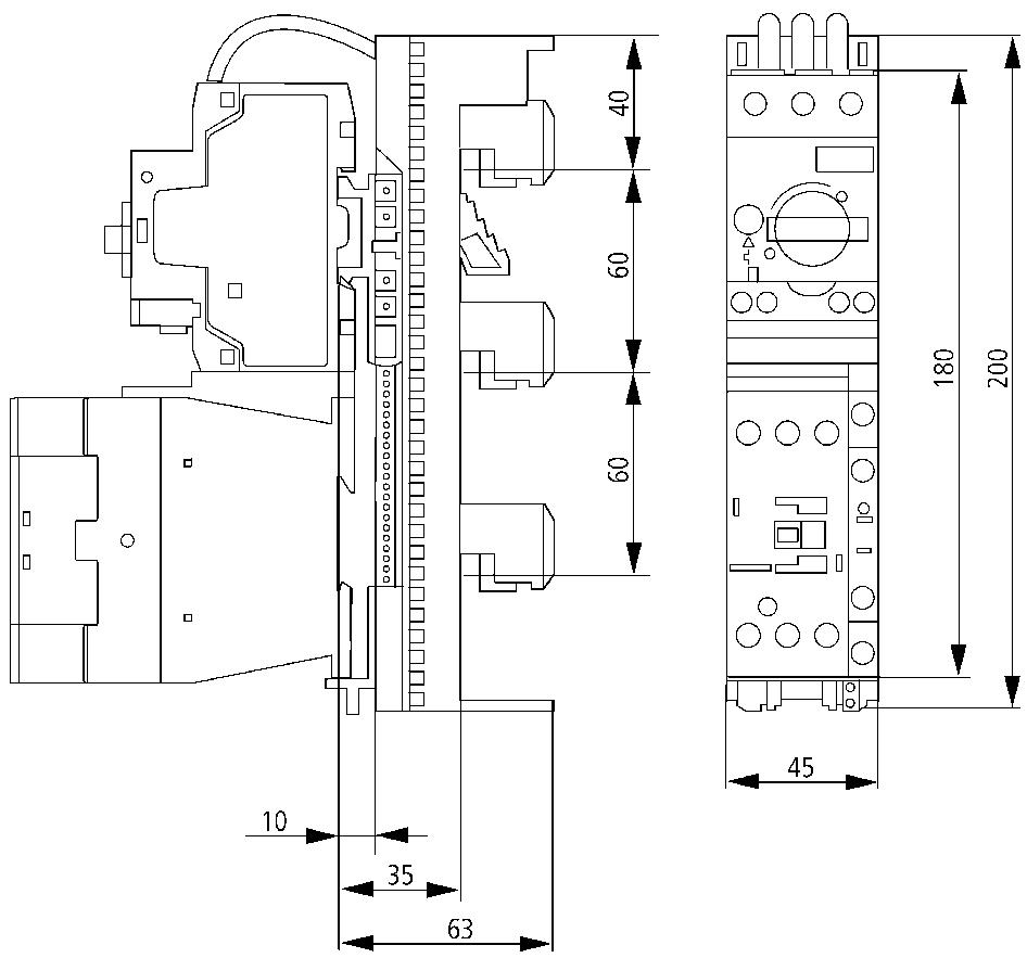
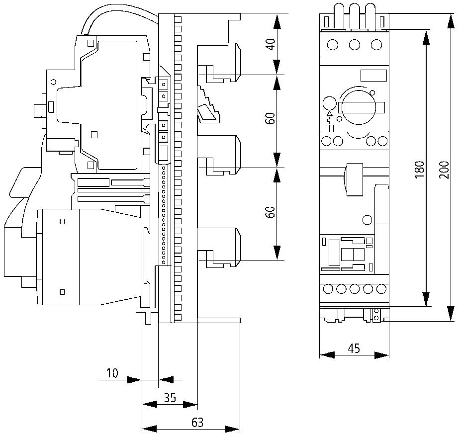
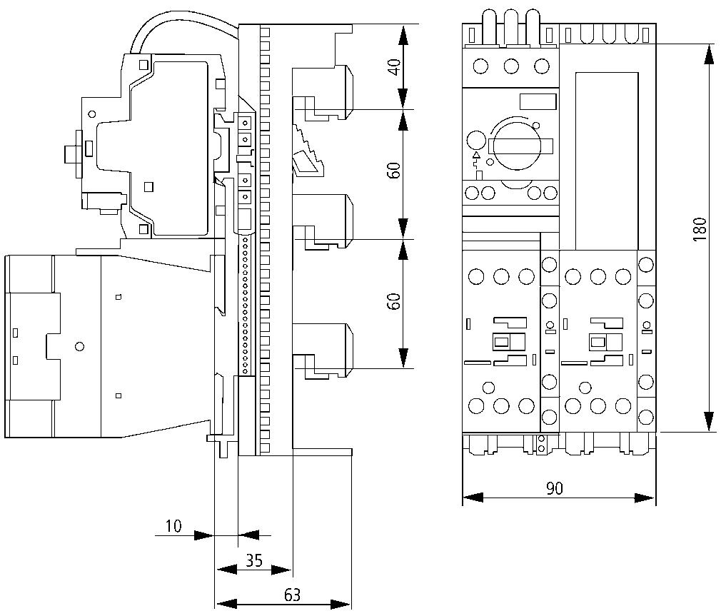
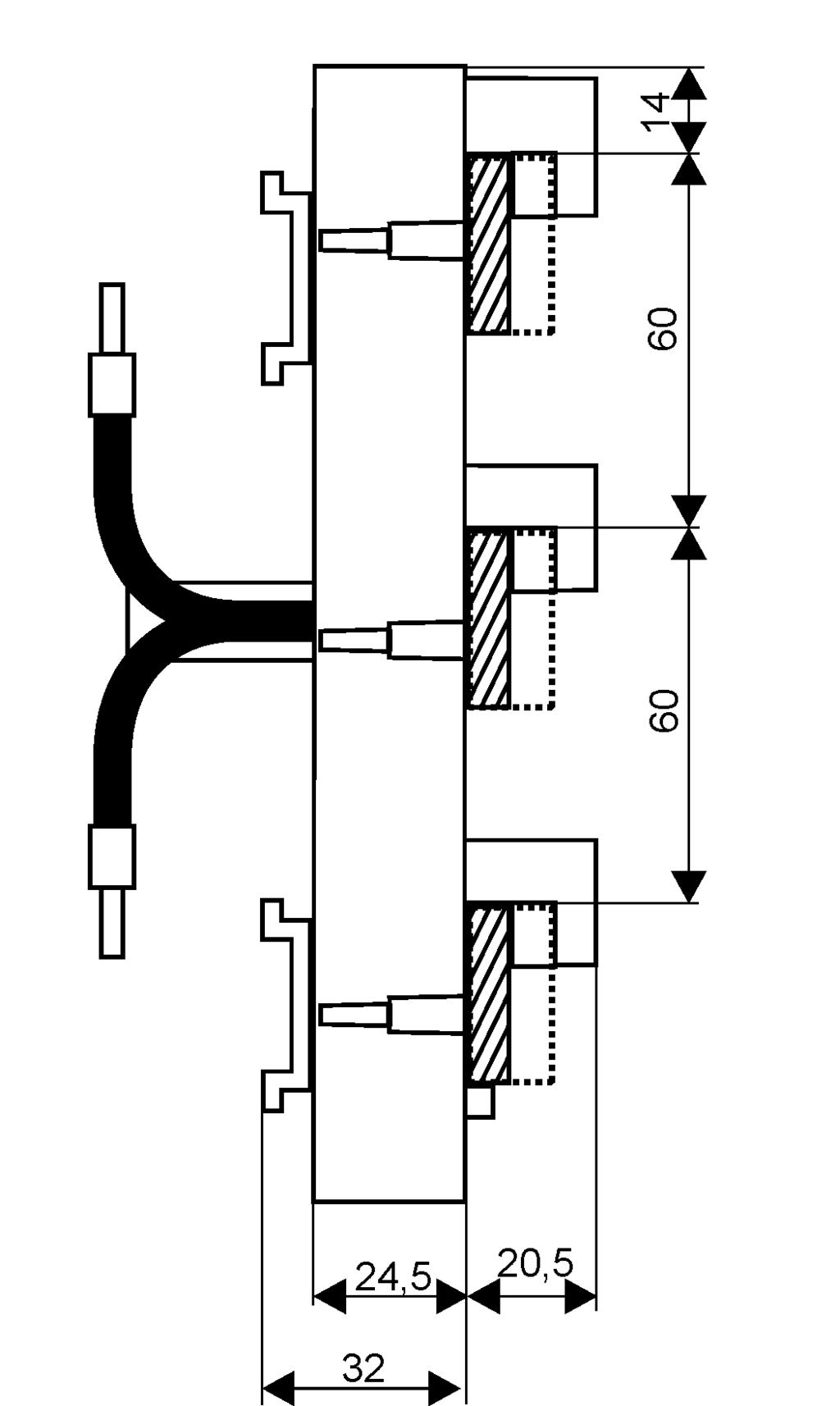
327 Busbar system SASY 60i Dimensions BBA0-25 BBA0R-25 BBA0-32 BBA0R-32 Z-SS-60-ADD/
Compact Distribution Boxes
 Compact Distribution Boxes Surface-Mounted and Flush-Mounted Compact Distribution Boxes xboard BC-O-...(-TW)-ECO / BC-U-...(-TW)-ECO Electrical Design according to IEC 439-1, -3 Degree of protection IP
IVS Distribution System. IVS - Table of Contents
 IVS - Table of Contents Overview System characteristics IVS System description Sheet steel wall-mounted DB for residential & functional buildings - IP30 Sheet steel wall-mounted DB for industrial applications
EWK Surface-mounted Field Distribution Boards, IP43
 VT94514 Degree of protection IP43, IK09 Protection class II, fully insulated 160 mm enclosure depth Complete with door and installation field for add-on devices Combined plug-type terminals for neutral
CS Wall-Mounted Sheet Steel Enclosures with Mounting Plate
 CS Wall-Mounted Sheet Steel Enclosures with Mounting Plate wa_vt08914 Available in 45 sizes... from 250x200x150 mm to 1200x1200x250 mm image01-ci The stable CS enclosures series made of solid sheet steel
xcomfort EWK Compact Distribution Boxes
 Product catalogue EWK Compact Distribution Boxes Release 2017-03 Energizing a world that demands more. We deliver: Electrical solutions that use less energy, improve power reliability and make the places
CS Wall-Mounted Sheet Steel Enclosures with Mounting Plate
 Moeller series CS Wall-Mounted Sheet Steel Enclosures with Mounting Plate Product Information CS Wall-mounted Sheet Steel Enclosures with Mounting Plate Accessories CS Wall-Mounted Sheet Steel Enclosures
Empty enclosures IEC 62208
 374 www.hensel-electric.de/en in accordance with for customized solutions and individual applications for example for low-voltage switchgear and controlgear assemblies i n accordance with the IEC 61439-series
Reliable Protection. Simplified Wiring. CI-K enclosure system
 CI-K small enclosures www.eaton.eu/ci-k Reliable Protection. Simplified Wiring. CI-K enclosure system The CI-K Enclosure System Reliable Protection. Simplified Wiring. The main job of an enclosure is to
Distribution Boards AT/U Series
 2-0 Distribution Boards AT/U Series Index Pages Product Features 2-3 AT/U Series Ordering Information 2-6 Equipped Distribution Boards 125 mm Distance Between Rows 2-10 Equipped Distribution Boards 150
14853 E. Hinsdale Ave. Centennial, CO USA Toll Free: / FAX:
 14853 E. Hinsdale Ave. Centennial, CO 80112-4240 USA Toll Free: 800-677-8942 / 303-680-5159 FAX: 303-680-5344 Hensel empty enclosures - the best choice for your electrical installation applications The
SINGLE DOOR BOXES. PAINT FINISH ETA standard epoxy polyester powder coating. Enclosure and door: colour RAL 7035 textured finish.
 ST SINGLE DOOR BOXES Enclosure and door manufactured from 1.5 mm thick sheet steel. Mounting plate manufactured from 2.5 mm thick sendzimir sheet steel. Enclosure and door: colour RAL 7035 textured finish.
Consumer units. Index. Pages. Consumer units UK500 series 1-3 Product features 1-12 Ordering information 1-18 Technical information
 Consumer units Index Pages 01 Consumer units UK500 series 1-3 Product features 1-12 Ordering information 1-18 Technical information Consumer units A300 series 1-21 Product features 1-22 Ordering information
3/2 Introduction. Unequipped Distribution Boards (Flat Pack) 3/6 8GK1 surface-mounting distribution boards
 3/6 8GK1 surface-mounting distribution boards") ALPHA 400 - DIN Wall-Mounted Distribution Boards /2 Introduction Unequipped Distribution Boards (Flat Pack) /6 8GK1 surface-mounting distribution boards Pre-Assembled Unequipped Distribution Boards /7
ALPHA 400 - DIN Wall-Mounted Distribution Boards /2 Introduction Unequipped Distribution Boards (Flat Pack) /6 8GK1 surface-mounting distribution boards Pre-Assembled Unequipped Distribution Boards /7
XL³ 400 metal distribution cabinets, free-standing enclosures and cable compartments
 87045 LIMOGES Cedex Telephone : 05 55 06 87 87 Fax : 05 55 06 88 88 XL³ 400 metal distribution cabinets, free-standing Cat. No(s) : 20103/04/05/06/07/08/18/19/23/ CONTENTS PAGE 1. General characteristics...
ENYSTAR Load Centers up to 250 A
 PASSION FOR POWER. up to 250 A according to IEC 61439-3 for commercial and industrial buildings Download at www.hensel-electric.en made in GERMANY since 1931 up to 250 A according to IEC 61439-3 for commercial
BOXES WALL-MOUNTING BOXES AND TERMINAL BOXES
 BOXES WALL-MOUNTING BOXES AND TERMINAL BOXES ST WALL-MOUNTING BOXES WITH BLANK DOOR STP WALL-MOUNTING BOXES WITH PLEXI DOOR ST/STP COMPLEMENTARY ACCESSORIES SDV TERMINAL BOXES WITH SCREWED COVER SDF TERMINAL
System pro E comfort Consumer units
 System pro E comfort Consumer units /0 2CPC 000 00 C020 Consumer units Consumer units Contents Consumer units for hollow-wall and for flush-mounting /2 Media enclosures /8 Control panels for flush-mounting
13.1. Range of Enclosures. KRONECTION Box A 2 for up to 2 pairs. Expert Knowledge. Short survey of the KRONECTION Box A 2 for up to 2 pairs
 KRONECTION Box A 2 for up to 2 pairs Short survey of the KRONECTION Box A 2 for up to 2 pairs The KRONECTION Box A 2, which is equipped with connection contacts on the right and left, serves as a line
Junction box for EKL light
 M EKL light Junction box Junction box for EKL light Features Chemical-resistant Temperature-resistant Flame-retardant Absolutely corrosion-proof Seawater-proof Description Polyester enclosures have proven
Distribution Board Pocket Guide 2010/2011 Consumer Units Compact Distribution Boards Accessories
 Distribution Board Pocket Guide 00/0 Consumer Units Compact Distribution Boards Consumer units UK00 series Consumer units UK00 series Consumer units series UK00 basic version without trim frame and door
xenergy Installation Mounting Systems Valid from April 2006
 www.moellerhome.net Product Catalogue 2006/2007 xenergy Installation Mounting Systems Valid from pril 2006 Reliably and safely controlling, switching and managing power. In industry, in buildings and in
BETA Switching Switches and Light Indicators
 Siemens AG 2008 BETA Switching /2 Product overview /3 5TE8 control switches / 5TE4 pushbuttons /2 5TE5 light indicators /5 5TE8 ON/OFF switches /22 5TE9 busbars /24 5TE switch disconnectors Siemens ET
1.1 Scope Characteristics General system description 1-2
 TABLE OF CONTENTS 1. INTRODUCTION 1.1 Scope 1-2 1.2 Characteristics 1-2 1.3 General system description 1-2 2. BOXES 2.1 Box overview 2-2 2.2 Box accessories 2-2 2.3 Box fittings 2-9 2.3.1 Flanges for increasing
SR1 multipurpose enclosures Enclosures for automation and distribution applications
 AU TO M AT I O N B OA R D S SR1 multipurpose enclosures Enclosures for automation and distribution applications Complete range of monobloc enclosures for small and mediumsize automation, command and distribution
Industrial Enclosures
 Industrial Enclosures Small enclosures from page 08 Polycarbonate enclosures PK... 0 Cast aluminium enclosures GA... 4 Terminal boxes KL... 6 E-ox E... 9 us enclosures G... 0 RiLAN Industrial IN... 4 Compact
Flush mounting enclosures. Pragma UP
 Flush mounting enclosures Presentation Flush mounting enclosures The appearance of this enclosure, its mechanical strength and its level of electrical safety make it a product fully suitable for residential
Product Data For FARNELL
 ae Product Data For FARNELL ae Uniset is / Varioset is ae EL ELECTRONIC KOMBI SYSTEM WALL MOUNTING Pole clamp For reliable, convenient fastening to round or square poles. For pole diameter/size:
DistriTon. Enclosures. Steel-plastic RZA Steel-sheet RZB Plastic RZG Plastic IP65 RZI
 Steel-plastic RZA Steel-sheet RZB Plastic RZG Plastic IP65 RZI Enhanced space Large number of terminals Invented for electricians Main advantages Steel-plastic RZA Enhanced space Large number of terminals
E N V I R O N M E N T A L P R O T E C T I O N F O R Y O U R C O N N E C T I O N S
 E N V I R O N M E N T A L P R O T E C T I O N F O R Y O U R C O N N E C T I O N S Controlwell presents a range of Junction Boxes manufactured from Halogen-free ABS, which offers superior resistance to
ACCESSORIES FOR SZE2 CABINETS
 ZPAS 143 DOORS Doors Intended for use instead of front solid door or rear panel. Maximum door opening angle: 120 Sheet steel textured powder paint, light grey (RAL 7035), stiffened profiles, brown smoked
Gland Plate 1.4mm mild steel. -Opening: Situated at the far rear of the enclosure to make cabling onto the mounting plate easier.
 14 SM SHEET STEEL ENCLOSURES ITH MOUNTING PLATE FOR ALL MOUNTING SM Delivery contents: Complete enclosure with mounting plate and fixing material, Blank flange with gasket and screws. Nylon washers for
photovoltaic NEW Safe product solutions conforming to standards for Industrial Electrical Power Distribution Systems with extended product range
 Professional Photovoltaic Distributors NEW with extended product range 10 11 Safe product solutions conforming to standards for photovoltaic plants Industrial Electrical Power Distribution Systems Solar
Moisture-proof cable branch boxes Ceiling distribution boxes Lamp suspension boxes Wall boxes Concrete wall boxes and accessories
 Branch and lustre terminals Apparatus and light terminals Porcelain terminals Screwless terminals Flat plug terminals Flat plug branch terminals Mains branch terminals Connection terminals Earthed wire
Your Source for Automation & Control Components. PREVENTS CONDENSATION with optional air ventilation element
 Your Source for Automation & Control Components PREVENTS CONDENSATION with optional air ventilation element Tough Flexible Safe GEOS - Industrial Outdoor Enclosure High quality materials and an innovative
APO ENCLOSURES. The bases are made of grey (RAL 7036), hot moulded glass fibre reinforced polyester
, hot moulded glass fibre reinforced polyester") APO ENCLOSURES APO - Modular polyester boxes - Complete with Base and Grey Lid IEC 60439-1 EN 60439-1 The range consists of nine boxes based on the 300 and 185 mm modules. IEC 60529 EN 60529 The bases
APO ENCLOSURES APO - Modular polyester boxes - Complete with Base and Grey Lid IEC 60439-1 EN 60439-1 The range consists of nine boxes based on the 300 and 185 mm modules. IEC 60529 EN 60529 The bases
TO ALL OUR CUSTOMERS. Poles
 Page 1 TO ALL OUR CUSTOMERS 1. NEWS: NEW 20-32-40A THERMOPLASTIC ENCLOSURES FOR THE ISOLATORS SERIES The thermoplastic ISOLATORS series offer has been expanded, introducing a range of products for 20,
Compact Sheet-Steel Light Fittings Series 6114/1
 > As 1- or 3-lamp version > Versions Pendant fitting Wall-mounting fitting Flush mounted fitting > Powder-coated steel or stainless steel > Central lock > All pole disconnection via NC switch in positive
Solar PV Enclosures 64
 Solar PV Enclosures 64 CDN36PT CDN24PT Watertight Distribution Enclosures (UV Rated) IP65, (Surface Mounted), (DC Rated DB Boards) Technical data Degree of protection is IP65 Test of resistance to glow
DOMINO Series surface mounting IP55
 Series surface mounting IP55 SERIES CONSUMER UNITS SURFACE MOUNTING VERSION - IP55 REFERENCE STANDARDS International standard IEC 60670 (989) and the Modification (994) Part : General requirements for
Rittal CM Compact System Enclosures
 Rittal CM Compact System Enclosures Compact class = Top class: Infinite possibilities R Compact enclosure on the outside, Top enclosure on the inside! Index Convincing details... 3 5 Compact system enclosures
Part-No. Article / Version Supply A Tilt foot bar of ABS, off-white RAL 9002 A
 *Mounting angle ( ) on the adapter serves as a support to locate the case in the right position. After attachment of the adapter, the mounting angles can be easily removed. Tilt foot bar, Case feet TILT
Distribution Boards. according to DIN 43871, DIN VDE 0603 and EN 60439
 Description Distribution Boards Page 58 Flush mounted Distribution Boards Page 60 Hollow-Wall Distribution Boards Page 60 Surface mounted Distribution Boards Page 6 Accessories Page 62 Special Distribution
Enclosures. flush-mounted/ /wall-mounted. PE, N, from 28 modules N for RCCB. PE, N, N for RCCBs. Part of standard supply
 DistriTon SUMMARY OF MODELS Type RZB RZG RZI Design steel-plastic steel-sheet plastic Installation flush-mounted / /into hollow walls flush-mounted/ /wall-mounted flush-mounted / wall-mounted / / into
Light Fitting for Fluorescent Lamps Series ECOLUX 6600
 > 1- or 2-lamp version: 18 W 36 W 58 W > Enclosure in polyester resin, glass fibre reinforced and cover in polycarbonate, impact-resistant > Quick fasteners www.stahl.de 10032E00 The light fittings series
IP65 enclosures orion plus
 IP65 enclosures orion plus One system for indoor and outdoor application Sheet steel or glass reinforced polyester - the orion plus enclosures are suited for harshest conditions and can be applied for
XL Distribution enclosures WORKSHOP SPECIFICATIONS
 800 Distribution enclosures WORKSHOP SPECIFICATIONS With its extensive ranges, the Legrand offer meets your quality standards and provides real freedom and simplicity of installation together with acknowledged
Emergency Light Fitting for Fluorescent Lamps Series ECOLUX 6608 Economy
 www.stahl.de > For fluorescent lamps 2 x 18 W and 2 x 36 W > Electronic ballast with integrated emergency light electronics > Battery is integrated in the lamp enclosure > For emergency light mode 1.5
RiLine mm system technology for the global market
 60 system technology for the global market 02 RiLine60 Busbar systems 3 and 4 pole Support + bars + contact hazard protection Flat copper bar system, see 276 in HB 33 PLS busbar system, see 278 in HB 33
ROSE Systemtechnik GmbH
 PRODUCT OVERVIEW 1 ROSE Systemtechnik GmbH The company was founded in 1969 and specializes in the development and production of high quality industrial enclosures, which are used in a variety of environmental
Compact Sheet-steel Emergency Light Fitting Series 6118/1
 www.stahl.de Compact Sheet-steel Emergency Light Fitting > Electronic ballast with integrated emergency light electronics for emergency light mode in case of power failure, charging of battery and automatic
YOUR WISH IS OUR COMMAND. Junction boxes. Catalogue-Junction boxes
 YOUR WISH IS OUR COMMAND Junction boxes Catalogue-Junction boxes 04 Index Index Hard rubber junction boxes Technical notes Type 1010 Type 1212 Type 1616 Type 1812 Type 2516 Type 1010- Type 2516 Pages 4-8
THE NEW TS IT RACK 8
 THE NEW TS IT RACK 8 Fast and reliable Fast Loosen the 48. (9 ) quickrelease fastener, slide into the correct position, and latch Reliable Maximum load capacity up to,000 N Convenience in perfection Interior
Commando Safetyswitch
 80 Commando Safetyswitch Commando Safetyswitches are manufactured from Polybutylene Terephthalate (PBT) for maximum impact resistance. The range offers a selection of IP54 and IP65 ratings to cover a variety
Molded-Plastic Distribution Systems
 Molded-Plastic Distribution Systems / Introduction ALPHA 8HP molded-plastic distribution systems /8 Empty enclosures / Modular installation devices /4 DIAZED/NEOZED fuse systems /7 NP fuse switch disconnectors
Spacial SF for Prisma Plus P system
 The Spacial SF range includes specific enclosure models for installing the Prisma Plus P : functional units and vertical and horizontal busbars The panels are subject to type tests according to standard
Overview of junction boxes
 Overview of junction boxes ariety Staying young A series Classic and still youthful: The wellknown junction boxes of the A series have had a makeover. Halogen-free thermoplastic is just as much of a hallmark
Variety at OBO. Overview of junction boxes
 ariety at OBO Overview of junction boxes ariety OBO junction boxes Large or small, classic or modern, for standard or special applications variety is at home in the field of OBO junction boxes. There s
Enclosure Mounting Screws For mounting enclosures through corner holes. Wood Screws
 Combination Kits Used to combine series specific enclosures to make larger units. Connect horizontally or vertically. Fitting Type Combination Kit Threaded with locknut seal for connecting sidewalls. Fits
PLASTIC BOXES - WIRE DUCTS - DIN RAILS - CABLE TIES
 PLASTIC BOXES - WIRE DUCTS - DIN RAILS - CABLE TIES TECNOMATIC CORP. www.tecnomatic.com PLASTIC BOXES TECHNICAL SPECIFICATIONS www.tecnomatic.com Material: ABS thermoplastic, heat resistant to 650 C, with
New products Ex Equipment 2015
 New products Ex Equipment 2015 ROSE Systemtechnik GmbH ROSE Systemtechnik GmbH was founded in Porta Westfalica, Germany, in 199 and is today one of the world s leading and innovative providers of industrial
2: Stylebox Stylebox 15 Overview B 2_ Complete Stylebox 15 Kits B 2_ Stylebox 15 Standard Kit B 2_8
 2.1 Stylebox 15 Overview 2_3 2.1.1 Complete Stylebox 15 Kits 2_7 2.1.2 Stylebox 15 Standard Kit 2_8 2.2 Stylebox 15 Smart 2_10 2.2.1 Width 2_11 2.2.2 Height ezel 2_11 2.2.3 Depth 2_11 2.2.4 Top Cover Panel
Panel building system
 Panel building system Ensto Cubo P Easy to use thermoplastic panel building system ensto.com Panel Building System Ensto Cubo Ensto Cubo P Panel Building System is designed in response to our customers
UCP polyester. UDP polyester. UCP Accessories. UDP Accessories. General Accessories. Mounting plates. Wall mounting brackets. Locks.
 160 POLYESTER ENCLOSURES UCP polyester 164 IP66; NEMA 4, 4X, 12, 13 IK10, IK07 H: 315-1035 W: 215-835 D: 170-300 UDP polyester 170 IP 65, 55; NEMA 4, 4X, 12, 13; IK 10, IK 07 H: 500-1250 W: 500-1250 D:
HP Series. Altech Corp. 35 Royal Road Flemington, NJ Phone (908) FAX (908)
 FAX (908)") Series The Series are economy junction boxes for lighter duty applications. The 70, 80 and 90 feature snap on covers, while the 100, 150 and 190 feature 4 quick release screws. Enclosures are supplied
Series The Series are economy junction boxes for lighter duty applications. The 70, 80 and 90 feature snap on covers, while the 100, 150 and 190 feature 4 quick release screws. Enclosures are supplied
Surface mounted distribution board - white door
 Distribution boards Distribution boards Home distribution board DIDO-E Rated current 63 A Rated voltage 400 V Degree of protection IP 40 Home distribution boards DIDO-E are available in two types: surface
Rondelec Armoire de trottoir
 Catalogue Rondelec Armoire de trottoir Magasin et showroom : Rue du Pré-de-la-Fontaine 19 117 Meyrin (Satigny) Service h/7j au 0 33 3 7 et sur www.fecsa.ch System Advantages n Flexible and all purpose
IP65/IP66 ABS/Polycarbonate Screw Lid Boxes
 IP65/IP66 ABS/Polycarbonate Screw Lid Boxes p Versatile, lightweight & durable p Choice of materials: polycarbonate for rugged applications or ABS as an economic alternative p IP protection for outdoor
BOXES AND BOARDS. Versatility and modularity of solutions and materials STANDARD HEAVY DUTY
 BOXES AND BOARDS Versatility and modularity of solutions and materials STANDARD HEAVY DUTY 8 BOXES AND BOARDS Versatility and modularity of solutions and materials STANDARD PRIMA topter empty distribution
workshop specifications Plexo³ IP 65 cabinets
 workshop specifications Plexo³ IP 65 THE GLOBL SPECILIST IN ELECTRICL ND DIGITL BUILDING INFRSTRUCTURES With their IP 65 weatherproof protection and optimised dimensions, Plexo³, from 2 to 4 x 18 modules,
Watertight control boxes. Adaptability Modularity Safety Reliability
 Offer daptability Modularity Safety Reliability Creating Control and Signalling Solutions for Harsh Environments The range of possibilities : wide choice - Select your box from the numerous ranges developed
Light Fitting for Fluorescent Lamps Series ECOLUX 6600
 > 1- or 2-lamp version: 18 W 36 W 58 W > Enclosure in polyester resin, glass fibre reinforced and cover in polycarbonate, impact-resistant > Quick fasteners www.stahl.de 10032E00 The light fittings series
Technical data. Material e-reinforced polyester in grey or black. Seal Neoprene (CR) round cord (siliconized)
 round cord (siliconized)") BERNSTEIN Series CP and CPS polyester enclosures are produced from highgrade e-reinforced polyester. Thanks to their reduced surface resistance (Ro < 109 Ohm), the black polyester enclosures meet the requirements
BERNSTEIN Series CP and CPS polyester enclosures are produced from highgrade e-reinforced polyester. Thanks to their reduced surface resistance (Ro < 109 Ohm), the black polyester enclosures meet the requirements
The Rittal Flex-Block base/plinth system
 The Rittal Flex-Block base/plinth system 50 Save time Fast assembly by simply clipping together the base/plinth components Easily bayed with toolless baying clip The enclosure is easily transported in
Linear Luminaire for Fluorescent Lamps Series EXLUX 6401
 > As wall, ceiling and pendant light fitting or pole mounted light fitting > Version with 2 lamps: 18 W, 36 W and 58 W > Central locking > All-pole disconnection by means of an N/C switch when the lamp
Emergency Luminaire with LED Series EXLUX 6009/1 Version IIC
 > For use in hazardous areas with gas group IIC > Emergency luminaire for wall, ceiling, pendant or pole installation > Latest LED technology with a high luminous efficacy and a long service life > Central
Linear Luminaire for Fluorescent Lamps Series EXLUX 6001
 > As wall, ceiling and pendant light fitting or side entry lamp > Version with 2 lamps: 18 W, 36 W and 58 W > Central locking > All-pole disconnection by means of an N/C switch when the lamp is opened
STANDARD SPECIFICATION FOR. LIGHTING AND DC DISTRIBUTION PANELS WITH MCBs DOCUMENT NO: 44LK-5100/E.02/011
 Page 1 of 6 STANDARD SPECIFICATION FOR LIGHTING AND DC DISTRIBUTION PANELS WITH MCBs Rev No. Issue Date Pages Rev Description Prepared By Checked By Approved By 0 15.07.2008 6 Issued for FEED MSJ VDV VDV
Emergency Luminaire with LED Series EXLUX 6409/1
 > Emergency luminaire for wall, ceiling, pendant or pole installation > Latest LED technology with a high luminous efficacy and a long service life > Central locking system > Weekly functional test > Annually
Wall-mounting steel enclosures suitable for any CRN and CRNG application
 Wall-mounting steel enclosures suitable for any CRN and CRNG application 1 2 3 4 5 6 1 Front rain gutter prevents the entry of water, oil or liquids, ensuring IP66 protection. 10 9 8 7 1/18 2 A complete
2: Ecokit Ecokit 11 Overview A 2_ Ecokit 11 Sub Rack Configuration A 2_ Width A 2_ Height / Depth A 2_6
 2: Ecokit 11 2.1 Ecokit 11 Overview 2_3 2.2 Ecokit 11 Sub Rack Configuration 2_5 2.2.1 Width 2_5 2.2.2 Height / Depth 2_6 2.2.3 Handles 2_6 2.2.4 Line Drawing 2_7 2.3 daptation Kits 2_8 2.3.1 daptation
also in ATEX Data Sheet Enclosures Klippon POK Glass Fibre reinforced Polyester Enclosures
 Data Sheet Enclosures Klippon POK Glass Fibre reinforced Polyester Enclosures also in ATEX Weidmüller s established range of Klippon POK GRP (Glass Fibre reinforced Polyester) enclosures has been updated
1.6 Accessories include tool-free snap-in technology options for air flow, cable management, shelves, power distribution units, etc.
 Rittal TS IT Rack Guide Specifications TS IT network server enclosure 1.0 General Description 1.1 Modular Free Standing Equipment Cabinet 1.2 Various combinations of dimensions: 1.2.1 Height: 48 /1200mm,
Emergency Light Fitting for Fluorescent Lamps Series 6009
 > As wall, ceiling and pendant light fitting or pole mounted light fitting > Version with 2 lamps: 18 W and 36 W > Central locking > All-pole disconnection via N/C switch when opening light fitting or
XL 3 -N SimPly, EfficiEnt And SAfE. 3 - PHASE distribution boards up to 250 A
 XL 3 -N 125 250 SimPly, EfficiEnt And SAfE 3 - PHASE distribution boards up to 250 A the global specialist in ElEctricAl And digital building infrastructures Xl 3 -n Comprehensive and reliable range for
Installation Enclosures
 Meter Boxes SMB's To house a single phase kilowatt hour meter * Standard kwh meter mounting * Surface or semi-flush installation * Square or triangular securing screw * Stand off for circuit breaker *
System Benefits Should you have any further questions, please contact our UL hotline at: +49 (0)9563/ Connection Technology EQUES Technology
9563/ Connection Technology EQUES Technology") System Benefits The small external dimensions of the 60mm busbar system allow for a wide range of busbars, so that it can be easily adapted to a wide range of currents. These features result in the particularly
System Benefits The small external dimensions of the 60mm busbar system allow for a wide range of busbars, so that it can be easily adapted to a wide range of currents. These features result in the particularly
Motor Circuit Breakers C3
 Motor Circuit Breakers C3 Motor protection rating up to 100 Amps Short circuit breaking capacity up to 100kA Phase failure protection DIN rail mounting Wide range of accessories Options and ordering codes
D-Sub adapter Cable entry protection with metric cable entries Cable entry protection with Pg cable entries
 Contents Page D-Sub adapter... 40.02 Han Split Hood... 40.04 Cable entry protection with metric cable entries... 40.06 Cable entry protection with Pg cable entries... 40.08 Coding for Hoods/Housings and
Explosion protected terminal boxes type, GHG 72.
 1 Technical data 1.1 Plastic terminal boxes GHG 721... ATX type examination certificate BVS 13 ATX 013 X Marking acc. to 94/9/G and standard ATX x (d e mb) II T5* -55 T amb +55 Gb x (d e mb) II T6* -55
Euromas-Polyester, an enclosure available
 Euromas-Polyester 8 Euromas-Polyester, an enclosure available in sizes made of 0% glassbead-reinforced polyester, has been designed to satisfy the highest standards. It makes it possible for the user to
Polycarbonate and ABS enclosures with quick release lid screws CT series
 Polycarbonate and s with quick release lid screws CT series The CT series of BERNSTEIN plastic enclosures are made from high-quality Polycarbonate or ABS. They are especially suitable for encapsulating
Plexo 3 weatherproof cabinets
 87045 LIMOGES Cedex Telephone: +33 (0)5 55 06 87 87 Fax: +33 (0)5 55 06 88 88 Plexo 3 weatherproof cabinets CONTENTS PAGES 1. Description, use.....1 2. Range, equivalence table...1 3. Overall dimensions...2
KDL cable entry system
 23 Advantages Assembling high-tech plugs securely in the control cabinet No need to keep cutting the plug off your cable! It is so easy to introduce preassembled plugs into the control cabinet. Cables
Junction boxes. X series
 Junction boxes X series X-TREME The new X series Extremely robust With the X series, OBO Bettermann can offer a range of junction boxes and empty housings that can withstand even the toughest mechanical
CABINETS AND ENCLOSURES. XL³ 400 and XL³ 800 GLOBAL SPECIALIST IN ELECTRICAL AND DIGITAL BUILDING INFRASTRUCTURES
 O S O O CABINETS AND ENCLOSURES XL³ 400 and XL³ 800 GLOBAL SPECIALIST IN ELECTRICAL AND DIGITAL BUILDING INFRASTRUCTURES II With its extensive ranges, the Legrand offer meets your quality standards and
FireBox T series The evolution of electrical function maintenance
 FireBox T series The evolution electrical function maintenance THINK CONNECTED. Basic principles and meaning electrical function maintenance Function Function maintenance for electrical systems Electrical
CS Wall-Mounted Sheet Steel Enclosures with Mounting Plate
 www.bcp-group.co.id CS Wall-Mounted Sheet Steel Enclosures with Mounting Plate Product Information CS Wall-mounted Sheet Steel Enclosures with Mounting Plate Accessories PT. Berkah Cipta Persada Kota Deltamas
Bocube. Colour: Graphite grey, similar to RAL 7024; light grey, similar to RAL 7035; special colours on request
 Bocube Detailed product information can be found on www.bopla.de - Patented, innovative, hinged quick-release catch technology without screws: open with a screwdriver, close by hand - 22 sizes, 132 standard
Product Data For FARNELL
 ae Product Data For FARNELL ae Uniset is / Varioset is ae EL ELECTRONIC KOMBI SYSTEM WALL MOUNTING Pole clamp For reliable, convenient fastening to round or square poles. For pole diameter/size:
Kaedra Weatherproof DIN Type Enclosures
 Multi 9 System Catalog Section 6 Additional System Devices Kaedra Weatherproof DIN Type Enclosures Applications Expandable enclosures for service, industrial, or equipment applications Protects against