TABLE OF CONTENTS FIGURES:
|
|
|
- Ernest Fletcher
- 5 years ago
- Views:
Transcription
1 TABLE OF CONTENTS 4.0 PROJECT COMPONENTS TRANSMISSION LINE DESIGN CHARACTERISTICS Structure Types Structure Foundations Conductors Insulators and Associated Hardware Overhead Shield (Ground) Wires Ground Rods Minor Additional Hardware Grid Interconnections NORTHERN AND SOUTHERN TERMINALS Northern Terminal Southern Terminal GROUND ELECTRODE FACILITIES COMMUNICATIONS SYSTEMS FIGURES: FIGURE 1 TYPICAL ±600 KV DC GUYED V-STRING LATTICE STRUCTURE FIGURE 2 TYPICAL ±600 KV DC SELF SUPPORTING LATTICE V-STRING STRUCTURE FIGURE 3 TYPICAL ±600 KV DC TUBULAR STEEL POLE V-STRING STRUCTURE FIGURE 4 TYPICAL ROW CROSS SECTIONS BY STRUCTURE TYPE FIGURE 5 TYPICAL 500 KV AC SINGLE CIRCUIT SELF SUPPORTING LATTICE STRUCTURE FIGURE 6 TYPICAL 230 KV AC SINGLE AND DOUBLE CIRCUIT POLE STRUCTURE FIGURE 7 TYPICAL AC/DC CONVERTER STATION FIGURE 8 TYPICAL SITE PLAN FOR GROUND ELECTRODE SYSTEM FIGURE 9 TYPICAL ABOVE GROUND CONSTRUCTION AT THE GROUND ELECTRODE FACILITY FIGURE 10 CO-LOCATED GROUND ELECTRODE LINE ON GUYED LATTICE STRUCTURE FIGURE 11 TYPICAL POLE STRUCTURE FOR OVERHEAD ELECTRODE LINE FIGURE 12 COMMUNICATIONS REGENERATION SITE MAP EXHIBITS: MAP EXHIBIT 2 NORTHERN TERMINAL AND GRID INTERCONNECTIONS MAP EXHIBIT 3 SOUTHERN TERMINAL AND GRID INTERCONNECTIONS MAP EXHIBIT 4 MAP EXHIBIT 5 NORTHERN TERMINAL AND GROUND ELECTRODE FACILITY PROPOSED AND ALTERNATIVE SITES AND SITING AREAS SOUTHERN TERMINAL AND GROUND ELECTRODE FACILITY PROPOSED AND ALTERNATIVE SITES AND SITING AREAS PLAN OF DEVELOPMENT PAGE i
2 TABLES: TABLE 3 TYPICAL ±600 KV DC TRANSMISSION LINE DESIGN CHARACTERISTICS TABLE 4 ±600 KV DC TRANSMISSION LINE DESIGN ALTERNATIVES POTENTIALLY USED IN CHARACTERISTIC SETTINGS TABLE 5 DESIGN CHARACTERISTICS OF TERMINALS TABLE 6 GROUND ELECTRODE FACILITIES DESIGN CHARACTERISTICS PLAN OF DEVELOPMENT PAGE ii
3 4.0 PROJECT COMPONENTS Sections 4.1 through 4.4 describe the typical design characteristics for the proposed TWE Project facilities and associated permanent and temporary land disturbance estimates: Section 4.1 the TWE Project transmission line, including structure designs and foundations, conductors, insulators and associated hardware, overhead shield (ground) wires, grounding rods, minor hardware, system interconnection lines and access roads. Section 4.2 the TWE Project Northern and Southern Terminals, including the AC/DC converter stations, substation equipment. Section 4.3 the TWE Project ground electrode systems, including the ground electrode facilities and low voltage electrode connector line(s). Section 4.4 the TWE communication system for command control of the transmission system. Appendix AA provides the revised indicative disturbance data tables for the project components by FEIS alternative route segments and an updated description of the methodology used to determine the indicative disturbance levels for access roads for analysis in the FEIS. 4.1 Transmission Line Design Characteristics The TWE Project proposed ±600 kv DC transmission line will be approximately 750 miles long, located in a ROW 250 feet wide. The design characteristics of the ±600 kv DC transmission line are summarized in Table 3 and are described in this section. 1 TransWest has determined that a ROW width of 250 feet is sufficient for the long-term maintenance and operation of the transmission line and will accommodate any of the transmission structure designs under consideration. Increased ROW width may be required in a small number of site specific locations to accommodate unusually long spans. These exceptions will be identified and addressed on a case-by-case basis during final design and engineering of the transmission line. ROW width for the TWE Project is based upon engineering studies that considered: Structure configuration (horizontal vs. vertical configurations), pole spacing, and insulator configuration (I-string vs. V-string insulator configurations); Operating voltage, elevation and clearance criteria (National Electrical Safety Code [NESC] and project-specific); Conductor size, weight, number and configuration of conductors in the bundle, tensions, and sag; Span length between structures and conductor blowout (conductor movement envelope under pre-defined wind conditions); 1 Short segments of 500 kv AC and 230 kv AC transmission lines will be required near the Northern and Southern Terminals to connect to the existing and planned regional transmission grid. The design characteristics of these transmission structures are described in Section PLAN OF DEVELOPMENT PAGE 4-1
4 Structure footprint (guyed vs. self-supported), terrain and maintenance access (space requirements for maintenance equipment at each structure site); Audible noise levels at the edge of the ROW; and Potential co-location with buried underground high pressure natural gas and other petroleum pipelines within the same corridor. The DC transmission line can be located in its ROW adjacent to the ROW for such pipelines. TABLE 3 TYPICAL ±600 KV DC TRANSMISSION LINE DESIGN CHARACTERISTICS FEATURE DESCRIPTION Physical Properties Line Length Miles per route segment depending on selected alternative. Proposed Structure Type: guyed steel lattice; Alternative Structure Types: selfsupporting steel lattice, tubular steel poles Structure Type Guyed steel lattice -120 to 180 feet; self-supporting steel lattice -120 to 180 feet; Structure Height tubular steel poles to 150 feet (special crossing structures may be in excess of 200 ft.) Guyed lattice to 1,500 feet; self-supporting steel lattice to 1,500 feet; Span Length tubular steel poles to 1,200 feet Four to eight - depending on structure type, terrain, and other factors to be identified Number of Structures per Mile through detailed design studies 250 feet; Increased ROW may be required in a small number of site specific locations ROW Width to accommodate unusually long spans Land Temporarily Disturbed Structure Work Area ROW width (250 ft) x 200 feet per structure ROW width (250 ft) x 500 feet for dead-end structure (two sites at all dead-end structures); Wire-Pulling and Tensioning Sites Material Storage Yards Staging Areas / Fly Yards Batch Plant Sites Guard Structures Structure Base 1 Regeneration Sites Existing Paved Roads 2 ROW width (250 ft) x 500 feet for mid-span conductor and shield wire (approximately every 9,000 feet); 100 x 500 feet for fiber optic cable set-up sites (approximately every 18,000 feet) Located approximately every 30 miles of transmission line Typical material storage yard area: approximately 20 acres Located approximately every 5 miles of transmission line Typical fly yards/staging areas: approximately 7 acres Located approximately every 15 miles of transmission line Stand-alone temporary batch plants, estimated size: approximately 5 acres 100 x 100 feet at road and existing overhead electrical line crossings Land Permanently Disturbed Guyed lattice (tangent) square feet (100 square feet mast foundation + 4 x 100 square feet for anchors) Self-Supporting Lattice (tangent) square feet (30 x 30 feet tower base) Self-Supporting Lattice (angle) - 1,225 square feet (35 x 35 feet tower base) Self-Supporting Lattice (dead-end) - 1,600 square feet (40 x 40 feet tower base) Tubular Steel Pole (tangent) - 40 square feet (7-foot diameter foundation) Tubular Steel Pole (dead-end/angle) square feet (two poles x eight-foot diameter foundations) Located approximately every 50 miles of transmission line, most located on the transmission line ROW and each approximately 10,000 square feet (100 x 100 feet). Access Roads Existing paved roads are typically highways and state routes that will be used for PLAN OF DEVELOPMENT PAGE 4-2
5 FEATURE Existing Dirt and Gravel Roads (no improvement) 2 Existing Dirt Road (with improvements) New Dirt Access Road (bladed) Overland Access Nominal Voltage Nominal Capacity Circuit Configuration Conductor Size DESCRIPTION travel to existing and new dirt roads to access the ROW. Existing dirt and gravel roads with wide (at least 14 feet), well graded or graveled surfaces that do not require improvement beyond regular maintenance, which could include, but not be limited to, blading of the road surface, placing gravel in low spots and repair of drainage structures within the previously disturbed area of road. Existing dirt roads that may require improvement. The bladed road surface may need to be widened to feet depending on terrain. Total disturbance, including that for drainage, cut and fill, may extend beyond the bladed road surface especially in steep terrain where the maximum total disturbance width will typically not exceed 52 feet, but will be determined in consultation with the land management agency or landowner on a case-by-case basis. Surface disturbance outside of the bladed road surface will be limited to the smallest area necessary while still providing a safe work area. Typically constructed with a 14 foot wide bladed surface with two or three foot berms or ditches on either side, but can be wider in steep and mountainous terrain because of cut and fill requirements according to ground slope. Based on the terrain and grade of the road, new bladed access roads to be constructed with an inslope or outslope design with water dips, water breaks and wings in the berm as necessary to manage water flow and mitigate erosion. Total disturbance, including that for drainage, cut and fill, may extend beyond the bladed road surface especially in steep terrain where the maximum total disturbance width will typically not exceed 52 feet, but will be determined in consultation with the land management agency or landowner on a case-by-case basis. Surface disturbance outside of the bladed road surface will be limited to the smallest area necessary while still providing a safe work area. Overland access ( drive and crush ) where terrain and soil conditions are suitable. No blading or grading required. Some areas may require taller vegetation to be removed while still leaving the root systems intact, as well as, rocks to be removed and placed outside the travel surface in order to utilize overland access. Access surface will typically not exceed 14 feet in width but will be determined in consultation with the land management agency or landowner on a case-by-case basis. Electrical Properties ±600 kv DC 3,000 MW (as measured at the Southern Terminal) DC Bi-Pole Bundled Approximately 1.5 inch diameter aluminum conductor steel reinforced (ACSR) conductor bundled with three or four sub-conductors per pole. 37 feet minimum at a conductor temperature of 176 degrees Fahrenheit ( F) Ground Clearance of Conductor Notes: 1 Structure types to be used in site-specific settings will be determined during engineering and design of the Agency Preferred Alternative. Tangent self-supporting lattice structures were used to calculate permanent disturbance since this structure type would result in greater disturbances per structure than the proposed guyed lattice structure. 2 Existing paved, gravel, and dirt public and private roads that can be used to access the FEIS corridor are part of the Backbone Access Road Network described in Appendix Z Revised Access Road Methodology for FEIS Memorandum (February 2014) Structure Types The TWE Project transmission line will be constructed primarily with guyed lattice structures (Figure 1). Self-supporting steel lattice and single shaft tubular steel poles (Figures 2 and 3) would be used in selective locations where engineering or other site-specific considerations determine that the guyed lattice steel structure is not appropriate. Table 4 indicates the general suitability of the transmission structure designs by characteristic settings. Figure 4 shows each structure design within a typical 250 foot-wide ROW. PLAN OF DEVELOPMENT PAGE 4-3
6 The guyed lattice structure shown on Figure 1 is the proposed tangent design for most locations due to its smaller disturbance area, constructability and overall cost considerations. In addition to tangent structure configurations, specialized structures will be engineered wherever the line must change direction. Specialized structures require the use of either self-supporting lattice or single shaft tubular steel poles. Each angle structure will be individually designed, taking into consideration both the degree of the angle and site-specific geologic conditions, to withstand the increased lateral stress of conductors pulling in two different directions. Angle structures are stronger and have deeper foundations than tangent structures. The term dead-end or strain structure typically refers to a structure where the conductors are separated and connected together (electrically) by a jumper. These dead-end structures are typically placed at locations where the transmission line significantly changes direction. The TWE Project will be designed in accordance with guidelines established by the Avian Power Line Interaction Committee (APLIC 1994, 2006, 2012). Appendix B provides the framework level Avian Protection Plan for the FEIS. During detailed engineering and design of the selected Alternative, a series of structure types will be designed to meet the project-specific design criteria. These project-specific design criteria address industry standards and guides, legislated requirements, anticipated environmental conditions, terrain, applications (settings) and land use. In addition to the common or standard structure types designed and to be used across the project, a small number of unique and special structures will be designed to address site-specific conditions such as long spans due to terrain or sub-regional conditions such as weak sandy soils, landslide areas or highly corrosive soils. TABLE 4 ±600 KV DC TRANSMISSION LINE DESIGN ALTERNATIVES POTENTIALLY USED IN CHARACTERISTIC SETTINGS CHARACTERISTIC SETTING Flat to Rolling Terrain Steep to Mountainous Terrain and Steep Side Slopes Open Lands GUYED STEEL LATTICE X SELF SUPPORTING STEEL LATTICE TUBULAR STEEL POLE * X X X Agricultural Fields, Urban Areas X X Highly constrained ROW Line Angle 0-2 X Heavier Line Angles and Dead-end X X Strain Structures * Should helicopter erection of structures be preferred or required, guyed lattice steel structures may be utilized in steep to mountainous terrain as long as specific structure locations do not have excessively steep side slopes. X PLAN OF DEVELOPMENT PAGE 4-4
7
8
9
10
11 4.1.2 Structure Foundations The guyed steel lattice towers will generally require one precast concrete support pedestal for the tower base and four anchors for guy cables. The typical precast concrete support pedestal will be three to six feet in diameter and four to six feet in depth. Due to site-specific characteristics, some foundations may require a cast-in-place reinforced concrete support pedestal. The anchors for attachment of the guy cables will be anchors designed for soil/rock conditions at each site. Self-supporting lattice towers will require four foundations with one foundation on each of the four corners (legs) of the lattice towers. The foundation diameter and depth will be determined during final design and are dependent on the type of soil or rock present at each specific site. Typically, the foundation for each leg of the structure will be a reinforced cast-in-place concrete drilled pier, with a typical diameter of three to four feet and a depth of approximately 12 to 25 feet. Foundations for dead-end and angles structures will be larger, typically ranging from five to eight feet in diameter and 20 to 50 feet in depth. Tubular steel pole towers will require one cast-in-place concrete foundation per steel pole. These tubular steel towers will be installed on a single reinforced concrete pier with anchor-bolts connecting the tubular pole base plate to the foundation. The foundation diameter and depth will be determined during final design and are dependent on the type of soil or rock present at each specific site. Foundations for these structures will typically be six to ten feet in diameter and 20 to 60 feet in depth. In a limited number of locations, specialized foundations may be required to address shallow rock, landslide prone areas, unstable soils, corrosive soils, weak sandy soils, shallow water table, etc. These site specific or sub-region specific foundation designs may include micro-pile, helical pile, grouted, epoxy, grillage, driven pile, vibratory pile and/or steel caisson type designs. All specialized foundations will be determined during final design Conductors Design Characteristics The proposed conductor for the TWE Project transmission line is an ACSR/TW (Aluminum Conductor Steel Reinforced/Trapezoidal Wire) conductor approximately 1.5 inches in diameter. Each pole of the ±600 kv bipole 2 line will be composed of three or four subconductors in a triple-bundle or quad-bundle configuration. The individual conductors will be bundled in either a triangular configuration (triple-bundle) or a diamond configuration (quad-bundle) with spacing of approximately 18 inches between subconductors. The bundled configuration is proposed to provide adequate current carrying capacity and to provide a reduction in audible noise and radio interference as compared to a single large-diameter conductor. Each ±600 kv subconductor will have a nonspecular finish 3. Ground Clearance Requirements and Guidelines Conductor phase-to-phase and phase-to-ground clearance parameters are determined in accordance with the NESC, ANSI C2, produced by the American National Standards Institute (ANSI). The NESC provides for minimum distances between the conductors and ground, crossing points of other lines and the transmission support structure and other conductors, and minimum working clearances 2 A bipole HVDC transmission line consists of two poles positive and negative. A pole may consist of one conductor or multiple conductors (i.e., sub-conductors) bundled together. 3 Non-specular finish refers to a dull finish rather than a shiny finish. PLAN OF DEVELOPMENT PAGE 4-9
12 for personnel during energized operation and maintenance activities. The clearance requirements for conductor heights above ground are based on the current and potential use of the land being crossed. The minimum ground clearance for the TWE Project ±600 kv DC conductor is 37 feet at a conductor temperature of 176 F. For a ±600 kv DC transmission line, the minimum conductor heights will typically range from 37 feet for range lands to 50 feet or more above railroad tracks. Clearances above highways would typically be 40 to 50 feet. Lands with center pivot irrigation or lands that are aerially sprayed would typically use a minimum ground clearance of 37 feet. The exact clearance criteria for each type of land use and each type of facility being crossed will be determined during detailed design. The clearance requirements for vertical separation at crossings over existing transmission lines are also governed by NESC 2012 Rule 233. In addition to the minimum NESC requirements, additional clearances or buffers are added to account for additional safety, construction tolerances, wire movements, differential wire temperatures, and utility specific requirements. The vertical separation typically ranges from approximately 25 feet for distribution and lower voltage lines to approximately 50 feet or more for 500 kv EHV or high voltage direct current (HVDC) lines. The exact clearance criteria for each voltage class being crossed will be determined during detailed design. Standard industry practice suggests that the higher voltage line would cross over the lower voltage line. This standard would be followed at the line crossing locations in coordination with each facility owner or manager. To optimize the crossing structure heights, the line crossing locations are typically at mid-spans of the lines being crossed and at right angles to each other. Depending on the terrain and heights of the facility being crossed, taller structures for the TWE Project transmission line may be required at the line crossing locations. Guard structures will be installed, if required, to protect underlying wires and structures during wire stringing operations. These guard structures intercept the wire should it drop below a conventional stringing height, preventing damage to underlying wires and structures. In addition to guard structures, during construction, the Contractor for the TWE Project will be required to coordinate with the owner or operator of the line being crossed to comply with outage and other utility-specific requirements. Due to the static nature of DC electrical and magnetic fields, the proposed transmission line will not induce any current in oil and gas well heads. The transmission line will be sited such that oil or gas wellheads, and associated above ground facilities at the wellhead, will not be located on the transmission ROW. Additionally, a 250-foot buffer from oil and gas wellheads will be used as a siting criteria for locating the final centerline of the ±600 kv DC transmission line. Section of this POD provides additional details concerning siting a DC or AC transmission line in proximity to pipelines Insulators and Associated Hardware As shown in Figures 1, 2, and 3, insulator assemblies for ±600 kv DC tangent structures will consist of two strings of insulators normally in the form of a V. These insulator strings are used to suspend each conductor bundle (pole) from the structure, maintaining the appropriate electrical clearance between the conductors, the ground, and the structure. The V-shaped configuration of the ±600 kv DC insulators also restrains the conductor so that it will not swing into contact with the structure in high winds. Dead-end insulator assemblies for ±600 kv DC transmission lines will use an I-shaped configuration, which consists of insulators connected horizontally from either a tower dead-end arm or a dead-end pole in the form of an I. Individual insulators for both suspension and dead-end applications will be composed of a single unit polymer (non-ceramic insulators). PLAN OF DEVELOPMENT PAGE 4-10
13 4.1.5 Overhead Shield (Ground) Wires Design Characteristics To protect the ±600 kv DC transmission line from direct lightning strikes, two lightning protection shield wires, also referred to as ground wires, will be installed on the peaks or top arms of each structure. Electrical current from lightning strikes will be transferred through the shield wires and structures into the ground. Standard Configuration In the standard configuration (all of the transmission line with the exception of short sections near the terminals where the overhead electrode line connecting the AC/DC converter station to the ground electrode facility is carried in the shield wire position), the shield wires will be composed of two wire types. Neither of these two wire types will have a non-specular finish. One of the shield wires will be composed of extra high strength steel wire approximately 0.5 inch in diameter. The second shield wire will be an optical ground wire (OPGW) constructed of aluminum and steel, which will carry 36 to 48 glass fibers within its core. The OPGW wire will have a diameter of approximately 0.65 inch. The glass fibers inside the OPGW will facilitate data transfer between the two AC/DC converter stations at the Northern and Southern Terminals. The data will be used for system control and monitoring. Electrode Line Configuration In short sections of the transmission line, near the terminals, both shield wires will also serve as the overhead electrode line connecting the AC/DC converter station to the ground electrode facility. The proposed conductor for the overhead electrode line in the shield wire position is a high temperature, low sag conductor approximately 1.0 inches in diameter. The OPGW, described above, will be carried on the structures at a lower elevation between the shield wires and the conductors Ground Rods A grounding system, which is distinct from the ground electrode system, will be installed at the base of each transmission tower and will consist of copper ground rods embedded in the ground in immediate proximity to the tower foundation, and connected to the tower by a buried copper lead. After the ground rods have been installed, the grounding will be tested to determine the resistance to ground. If the resistance to ground for a transmission tower is excessive, then counterpoise will be installed to lower the resistance. Counterpoise consists of a bare copper-clad or galvanized-steel cable buried a minimum of 12 inches deep, extending from one or more legs of a tower for approximately 100 feet within the ROW Minor Additional Hardware In addition to the conductors, insulators, and overhead shield wires, other associated hardware will be installed on the structures as part of the insulator assembly to support the conductors and shield wires. This hardware will include clamps, shackles, links, plates, and various other pieces composed of galvanized steel and aluminum. Other hardware not associated with the transmission of electricity may be installed as part of the Project. This hardware may include aerial marker spheres or aircraft warning lighting as required for the conductors or structures per FAA regulations (FAA 2000, 2007). Tower proximity to airports and tower height are the determinants of whether FAA regulations would apply based on an assessment of wire/tower strike risk. The Applicant does not anticipate that tower lighting will be required because PLAN OF DEVELOPMENT PAGE 4-11
14 proposed towers will be less than 200 feet tall and will be located to the greatest extent to avoid airport impacts. However, if special circumstances (e.g., a tall crossing) require structures taller than 200 feet, FAA regulations regarding lighting and marking will be followed Grid Interconnections The TWE Project will need to connect to planned or existing 500 kv and 230 kv transmission grids in Wyoming and to existing 500 kv transmission grids in Nevada, near each terminal. Specific structure types are not known at this time and will be determined during final engineering and design. A typical self-supporting lattice structure, used for a single circuit 500 kv AC line connection, is shown on Figure 5. Typical single circuit and double circuit 230 kv AC single pole structures are shown on Figure 6. The components for the 500 kv and 230 kv structures including foundations, conductors, insulators, and associated hardware, overhead shield (ground) wires, and grounding rods, are similar to those described for the ±600 kv DC transmission line. PLAN OF DEVELOPMENT PAGE 4-12
15
16

17 4.2 Northern and Southern Terminals The terminal stations will be designed to include the AC/DC converter station and an adjacent AC substation. The AC/DC converter station will include a ±600 kv DC switchyard, AC/DC conversion equipment, transformers, and multiple equipment, control, maintenance and administrative buildings. There will be two buildings to house the AC/DC conversion equipment, each approximately 200 feet long by 80 feet wide by 60 to 80 feet high. Additionally, there will be smaller buildings to house the control room, control and protection equipment, auxiliary equipment, and cooling equipment. The AC substations will be either a 500/230 kv substation (Northern Terminal) or a 500 kv substation (Southern Terminal). The AC substations will include a switchyard, transformers, control equipment, and control buildings. Figure 7 is a photograph of a representative AC/DC terminal (converter station and adjacent AC substation). FIGURE 7 TYPICAL AC/DC CONVERTER STATION PLAN OF DEVELOPMENT PAGE 4-15
18 Table 5 summarizes the general design characteristics of the terminals. TABLE 5 Northern Terminal Southern Terminal Line Length Structure Type Number of Structures per Mile ROW Width Storage and Concrete Batch Plant Structure Work Areas for Interconnection Lines Wire-Pulling, Tensioning and Splicing Sites for Interconnection Lines Converter Station and Substations Structure Base 500 kv Interconnection Line Structure Base 230 kv Interconnection Line New Access Roads DESIGN CHARACTERISTICS OF TERMINALS DESCRIPTION OF TERMINALS Six 500 kv AC line positions, two 500/230 kv transformer banks, twelve 230 kv line positions, two AC filter bank line positions, two reactive support device positions, two DC line positions with transformers, converter building(s), and AC and DC filter yards. The reactive support equipment will require other structures and building development within the proposed complex. Maintenance and storage facilities will be developed as required and as appropriate for this remote location. Certain assigned shift operators, maintenance staff, and site security staff may be on-site at all times, although no permanent residence(s) will be established. On-site fire protection and emergency/security staff will support operations and maintenance staff at the facility in accordance with state, county, and federal requirements. Six 500 kv AC line positions, two 500 kv AC filter line positions, two DC line positions with transformers, converter building(s), and AC and DC filter yards. Maintenance and storage facilities will be developed as required and as appropriate for this remote location. Certain assigned shift operators, maintenance staff, and site security staff may be on site at all times, although no permanent residence(s) will be established. On site fire protection and emergency/security staff will support operations and maintenance staff at the facility in accordance with state, county, and federal requirements. Physical Properties of Interconnection Lines Miles per interconnection line Self supporting lattice for 500 kv line Single pole tubular steel for 230 kv line Approximately six (230 kv structure) and four (500 kv structure) 125 feet for 230 kv line 250 feet for 500 kv line Land Temporarily Disturbed 7.5 acres 200 x 200 feet per 230 kv structure; approximately 6 per mile of line (Northern Terminal only) 250 x 200 feet per 500 kv structure; approximately 4 per mile of line ROW width x 500 feet mid-span conductor and shield wire sites every 9,000 feet and fiber optic set-up sites every 18,000 feet Land Permanently Disturbed 205 acres (N. Terminal), 140 acres (S. Terminal) Self supporting lattice (tangent) 1,225 sq. feet (35 x 35 feet tower base) Self supporting lattice (angle) 1,600 sq. feet (40 x 40 feet tower base) Self supporting lattice (dead-end) 2,025 sq. feet (45 x 45 feet tower base) Single pole tubular (tangent) 40 sq. feet Single pole tubular (angle) 45 sq. feet Single pole tubular (dead-end) 50 sq. feet See Section 5.2.1: Access Road Construction and Appendix Z Revised Access Road Methodology for FEIS Memorandum (February 2014) PLAN OF DEVELOPMENT PAGE 4-16
19 4.2.1 Northern Terminal The Northern Terminal will consist of an AC/DC converter station (a ±600 kv DC switchyard and a converter building containing power electronics and control equipment), a 500/230 kv AC substation, and a 230 kv AC substation. The facilities will be located on private lands in Carbon County, Wyoming, approximately 2.5 miles southwest of the town of Sinclair, Wyoming. The Northern Terminal will connect to the existing Platte Point of Rocks 230 kv line located within a mile of the terminal. The Northern Terminal will also connect to the planned Energy Gateway West and Gateway South 500 kv transmission lines being developed by PacifiCorp. The Northern Terminal will require the following components: An AC/DC converter station approximately 30 acres in size. A 500/230 kv AC substation approximately 135 acres in size. A 230 kv AC substation approximately 40 acres in size. An electrical connection from the AC/DC converter station to the ±600 kv DC transmission line connecting to the Southern Terminal. All facilities for this connection are incorporated into the ±600 kv DC transmission line. Two electrical connections from the proposed single circuit Energy Gateway West 500 kv transmission line to the 500/230 kv substation. These connections will connect the Northern Terminal to both the Aeolus and Anticline substations via the Energy Gateway West 500 kv transmission line. These two connections may require 500 kv transmission facilities, assumed to be four miles total or less in length, to connect the 500/230 kv substation to the route of the Energy Gateway West 500 kv transmission line. Figure 5 shows a typical structure design for the 500 kv transmission line connections. Two electrical connections from the proposed single circuit Energy Gateway South 500 kv transmission line to the 500/230 kv Substation. These connections will connect the Northern AC/DC converter station to both the Aeolus and Mona Substations via the Energy Gateway South 500 kv transmission line. These two connections may require 500 kv transmission facilities, assumed to be four miles total or less in length, to connect the 500/230 kv substation to the route of the Energy Gateway West 500 kv transmission line. Figure 5 shows a typical structure design for the 500 kv transmission line connections. Two electrical interconnections to the existing Platte Point of Rocks 230 kv line, which will be rerouted into and out of the 230 kv substation. This 230 kv connection is assumed to require four miles or less of double circuit 230 kv transmission line. Figure 6 shows a typical structure design for the 230 kv transmission line connections. Up to six electrical interconnections from proposed and planned generation facilities by 230 kv transmission lines. Figure 6 shows a typical structure design for the 230 kv transmission line connections. Construction of the Northern Terminal is estimated to require approximately 520 acres. Approximately 250 acres of this area or less will be permanently dedicated for the AC/DC converter station and substations, terminal access road, transmission line structures, and interconnection line access roads. Approximately 205 acres will be fenced for the Northern Terminal. Approximately 275 PLAN OF DEVELOPMENT PAGE 4-17
20 acres are estimated to be temporarily disturbed for construction work areas, including land for storage and a concrete batch plant, transmission line structure work areas, and pulling, tensioning and splicing sites. The general planned locations for the Northern Terminal and grid interconnections are shown on Map Exhibit 2. The location for the Northern Terminal site is proposed to be within the siting area shown. The final site location will be determined during final engineering and design. The criteria used in selecting the siting area and the final site location are: Land Ownership - use of private lands over public lands is preferable. Land Use - other current and planned land uses in the area, in particular other infrastructure that is being planned and permitted. Environmental Constraints - avoidance of sensitive resources, including sensitive wildlife habitats, cultural resource sites, wetlands, and major drainages. Topography - use of level dry land over more rugged terrain is preferable. Access to the TWE Project transmission line corridors coordinated with other existing and planned infrastructure and which minimize line crossings. Interconnections with existing, planned, and potential transmission lines such that line crossings are minimized, and conflicts with other existing and planned infrastructure are avoided. Map Exhibit 2 illustrates a conceptual layout of the Northern Terminal and associated 230 kv and 500 kv connections to existing and planned facilities. The location of the Northern Terminal and the alignments of the 230 kv and 500 kv transmission line connections will be located within the proposed terminal siting area and will be determined during final design. 4 Based on final ownership/operating agreements and interconnection contracts, it is possible that the 500/230 kv AC substation and/or the 230 kv AC substation could each be broken into two separate facilities. The total required acreage of the separate 500/230 kv AC substation(s) and the 230 kv AC substation(s) would not be greater than the 175 acres (135 plus 40) described above. The total fenced acreage for the Northern Terminal would be 205 acres in either one contiguous facility or 70 acres in one location and an additional 135 acres in a remote location. Land outside of this area would be used for access roads. Terminal access will require an estimated 10 acres of permanent disturbance. With the exception of the associated interconnection lines, no other permanent development outside of the fenced area for this facility is anticipated. 4 The three major components of the Northern Terminal (AC/DC converter station, 500/230 kv AC substation, and 230 kv AC substation) are planned to be co-located and contiguous. Although each of these three components are stand-alone facilities and could be located on separate parcels connected together by short transmission lines, it is common practice and preferable for the AC/DC converter station and 500/230 kv AC substation(s) to be located adjacent to each other. Although it is also preferable to locate the 230 kv AC substation next to the 500 kv AC substation, depending on the availability of space and other constraints in this area, these stand-alone facilities could be separated by a distance of up to two miles. PLAN OF DEVELOPMENT PAGE 4-18

21
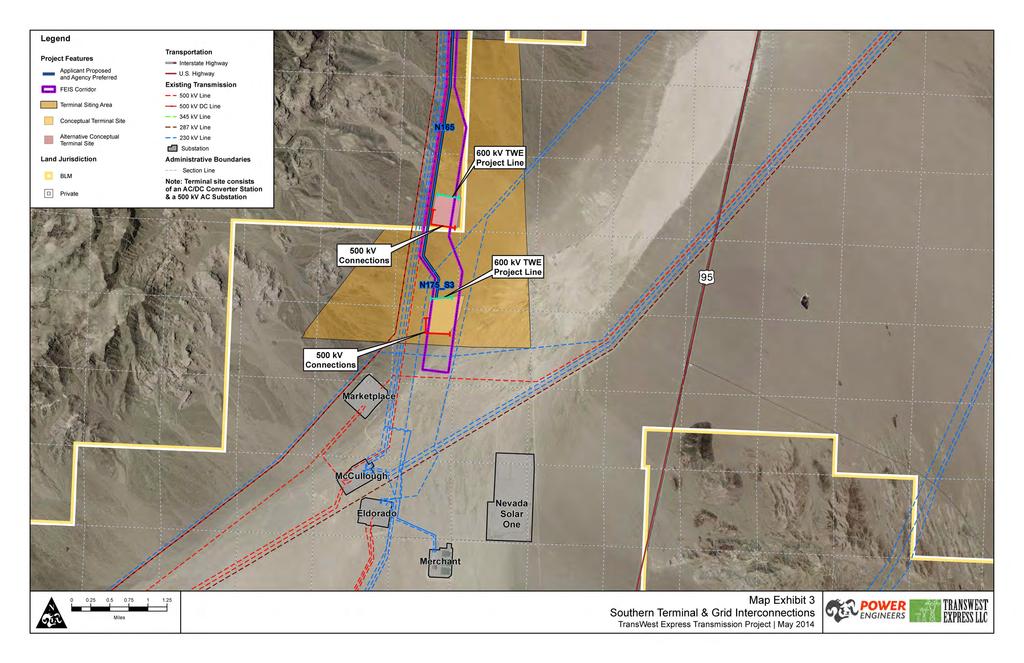
22 4.2.2 Southern Terminal The Southern Terminal will consist of an AC/DC converter station (a ±600 kv DC switchyard and a converter building containing power electronics and control equipment) and a 500 kv AC substation. The facilities will be located in the Eldorado Valley on private or BLM administered land, approximately 15 miles south of Boulder City, in Clark County, Nevada. The Southern Terminal will connect to all four of the existing 500 kv substations located at the Marketplace Hub. These four substations are the Mead, Eldorado, Marketplace, and McCullough substations. The Southern Terminal will require the following components: An AC/DC converter station approximately 30 acres in size. A 500 kv AC substation approximately 110 acres in size. An electrical connection from the AC/DC converter station to the ±600 kv DC transmission line connecting to the Southern Terminal. All facilities for this connection are incorporated into the ±600 kv DC transmission line. Two electrical connections from the existing Mead Marketplace 500 kv transmission line to the new 500 kv AC substation. These connections will connect the Southern Terminal to both the Mead and Marketplace substations via the existing Mead Marketplace 500 kv transmission line. These two connections may require 500 kv transmission facilities, assumed to be five miles total or less in length, to connect the new 500 kv AC substation to the existing Mead Marketplace 500 kv transmission line. Figure 5 shows a typical structure design for the 500 kv transmission line connections. Construction of a 500 kv transmission line from the new 500 kv AC substation to the Eldorado Substation. This single circuit 500 kv transmission line is estimated to be five miles in length or less. Figure 5 shows a typical structure design for the 500 kv transmission line connections. Construction of a 500 kv transmission line from the new 500 kv AC substation to the McCullough Substation. This single circuit 500 kv transmission line is estimated to be five miles in length or less. Figure 5 shows a typical structure design for the 500 kv transmission line connections. Although not anticipated at this time, one or more of the existing 138/230 kv lines within the Proposed Terminal Siting Area may need to be re-routed/re-configured to accommodate the Southern Terminal due to congestion within the area. If necessary, this reroute or reconfiguration of 138/230 kv transmission line facilities is not anticipated to impact more than a total of five miles of line. Figure 6 shows a typical structure design for the 230 kv transmission line connections. Construction of the Southern Terminal on private land is estimated to require approximately 555 acres whereas the terminal construction on BLM land is estimated to require approximately 750 acres (differences in construction acreages due to lengths of access roads and lengths of 500 kv transmission lines). Approximately 230 to 260 acres of this area will be permanently dedicated for the AC/DC converter station and switchyards, terminal access road, transmission line structures, and interconnection line access roads. Approximately 140 acres will be fenced for the Southern Terminal. Approximately 335 acres on the private land site and 500 acres of the BLM land site are estimated to PLAN OF DEVELOPMENT PAGE 4-20
23 be temporarily disturbed for construction work areas, including land for storage and a concrete batch plant, transmission line structure work areas, and pulling, tensioning and splicing sites. The general planned location for the Southern Terminal and grid interconnections are shown on Map Exhibit 3, which illustrates a conceptual layout of the Southern Terminal and associated 500 kv connections to existing substations. The location of the Southern Terminal and the alignments of the 500 kv transmission line connections will be located within the terminal siting area and will be determined during engineering and design. 5 Terminal access on the private land site and BLM land site will require an estimated 15 and 20 acres of permanent disturbance, respectively. With the exception of the associated interconnection lines, no other permanent development outside of the fenced area for this facility is anticipated. 4.3 Ground Electrode Facilities Two ground electrode facilities are proposed, one connecting to the Northern Terminal and one connecting to the Southern Terminal. Table 6 provides the design characteristics of the ground electrode facilities. The proposed site for the northern ground electrode facility is termed Bolten Ranch and shown on Map Exhibit 4. This proposed site is suitable for use with all route alternatives. The three alternative sites shown on Map Exhibit 4 would also connect to the Northern Terminal: Separation Flat, Eight Mile Basin, and Separation Creek. The proposed site for the southern ground electrode facility is termed Mormon Mesa-Carp Elgin Road and shown on Map Exhibit 5. 6 This proposed site is suitable for use with all route alternatives. The two alternative sites shown on Map Exhibit 5 would also connect to the Southern Terminal: Halfway Wash E. and Halfway Wash-Virgin River. The proposed and alternative ground electrode sites were selected based on feasibility studies that considered surface and deep earth geology, proximity to the alternative routes, proximity to underground infrastructure (oil, gas and water wells, pipelines, etc.), environmental constraints, and topography. Major factors in selecting the alternative sites were: 1. Geology and ground resistivity of the area. The primary need is for deep sedimentary basins with large volumes of sediment having a low resistivity. Locations with potentially high resistance geologic formations that could potentially interfere with the current path are generally avoided. 2. Distance from grounded metallic infrastructure that might be negatively impacted by DC ground currents. In general, this consideration results in the electrode site being a few miles or more from power plants, electrical substations, underground pipelines, and active oil or gas wells. The ground electrodes cannot be located within two miles of major pipelines due to the risk of having a corrosive impact on nearby metallic structures. Ground electrodes located 5 The two major components of the Southern Terminal (AC/DC converter station and the 500 kv AC substation) are planned to be co-located and contiguous. Although these two components are stand-alone facilities and could be located on separate parcels connected together by short transmission lines, it is common practice and preferable for the AC/DC converter station and 500 kv AC substation to be located adjacent to each other. 6 Map Exhibits 4 and 5 show both the proposed and alternative ground electrode sites and siting areas PLAN OF DEVELOPMENT PAGE 4-21
24 within 2 to 10 miles of major pipelines may require additional or modified corrosion protection systems. 3. Environmental constraints such as special federal and state management areas, sensitive resources (e.g., wetlands), and special status species (e.g., sage-grouse). Secondary consideration was given to topography as it would be impractical to drill the ground wells in mountainous topography. More detailed information will be required during final engineering and design to make a final determination of the location of the proposed ground electrode sites including: a) availability of public lands or private lands; b) detailed measurements of ground resistivity; c) chemical and thermal characteristics of the soil at the site; and d) a detailed analysis of grounded metallic infrastructures in the area. TABLE 6 GROUND ELECTRODE FACILITIES DESIGN CHARACTERISTICS FEATURE DESCRIPTION Physical Properties of Overhead Electrode Lines Line Length Miles per electrode line Structure Type Wood / wood pole equivalent for low voltage electrode line (similar to 34.5 kv line) Number of Structures per Mile 18 ROW Width 50 feet Land Temporarily Disturbed Ground Electrode Site Material Storage Yards Structure Work Areas for 34.5 kv Line Wire-Pulling, Tensioning and Splicing Sites for Interconnection Lines Ground Electrode Site 65 acres 10 acres per electrode site ROW (50 ft) x 100 feet 75 x 150 feet two at every dead-end 75 x 100 feet mid-span conductor site every 9,000 feet Land Permanently Disturbed 0.5 acres Well Access Structure Base Electrode Line (similar to 34.5 kv line) New Access Roads 5 acres Wood / wood pole equivalent (tangent) 16 sq. feet Wood / wood pole equivalent (angle) 25 sq. feet plus 25 sq. feet per anchor (2 per structure location) Wood / wood pole equivalent (dead-end) 36 sq. feet plus 25 sq. feet per anchor (4 per structure location) See Section 5.2.1: Access Road Construction and Appendix Z Revised Access Road Methodology for FEIS Memorandum (February 2014) Once construction is completed, approximately 0.5 of an acre, or less, near the center of the electrode containing the control house will be fenced. Agricultural land uses outside the fenced area such as grazing and cultivated crops would be permissible. These two ground electrode facilities will be built, each within approximately 100 miles or less of the Northern and Southern Terminals, to establish and maintain electrical current continuity during normal operations and immediately following an unexpected outage of one of the two poles (or circuits) of the ±600 kv DC terminal or converter station equipment. PLAN OF DEVELOPMENT PAGE 4-22
25 Each ground electrode facility will consist of a network of approximately 60 deep-earth electrode wells arranged along the perimeter of a circle expected to be about 3,000 feet in diameter. All wells at a site will be electrically interconnected and wired to a small control building via low voltage underground cables. A typical site plan for a ground electrode system is shown in Figure 8 and a photograph of a typical above ground facility is provided in Figure 9. A low voltage electrode line will be required to connect the ground electrode facilities to the AC/DC converter stations (at the Northern and Southern Terminals). To the extent practical, the overhead electrode line will be co-located on the ±600 kv DC structures in the overhead shield wire position. The overhead electrode line (connecting the terminal to the ground electrode facility) will occupy both shield wire positions from the Southern Terminal to the location where the electrode lines leaves the ±600 kv DC transmission line. Figure 10 shows a typical structure with the electrode line in the shield wire position with the fiber optic line (OPGW) located between the shield wires and the DC conductors. Where the electrode line diverges from the ±600 kv DC transmission line, it will be located on single pole structures, similar to those used for a modified 34.5 kv subtransmission line, built within a separate 50-foot-wide ROW. The electrode line will consist of two, high temperature, high capacity conductors. Figure 11 shows a typical single pole structure design that would be used for the overhead electrode line. During a DC transmission disturbance where one pole (or circuit ) becomes inoperable, the ground electrodes will carry a short-term large current that was previously flowing in the inoperable pole. The electrodes will be sized and designed to disperse this current into the ground at levels which are safe for people and animals in the vicinity. Such contingency conditions that result in high ground electrode currents are most often the result of an unexpected outage on the transmission line or equipment in the AC/DC converter station. The high current operation of the ground electrode facilities and the use of the earth as a return path is limited to unexpected emergency conditions and typically only operated for 10 minutes to less than an hour following the loss of a pole. For planning and preliminary engineering purposes, 12 to 16 unexpected disturbances resulting in the loss of a pole are anticipated on a yearly basis. Although the ground electrode facilities will be designed to operate at high current levels for up to 200 hours per year, typical yearly use at high currents is expected to be less than 30 hours per year. The use of these ground electrode facilities allows system operators to maintain a portion of the TWE Project s power transmission capacity to support power network reliability. This feature will allow critical time for network operators to determine the extent of the electrical disturbance and reconfigure the transmission and generation systems into a more stable configuration that minimizes disruption of customer loads. PLAN OF DEVELOPMENT PAGE 4-23
26
27

28 FIGURE 9 TYPICAL ABOVE GROUND CONSTRUCTION AT THE GROUND ELECTRODE FACILITY PLAN OF DEVELOPMENT PAGE 4-26
29
30

31

32
33 4.4 Communications Systems The TWE Project will require a number of critical telecommunications support subsystems. These systems will be configured and designed to support the overall availability and reliability requirements for the operation of the HVDC terminal facilities and supporting substations. To provide secure and reliable communications for the control system real-time requirements, protection and day-to-day operations and maintenance needs, a mix of telecommunications systems will be used. The primary communications for protection and control will be provided via the one OPGW installed in the shield wire position on the transmission line. For redundancy purposes, a secondary communications path will be provided via existing or expanded/upgraded microwave systems or existing alternate buried fiber paths in the TWE Project region. In addition to protection and control, the communications system will be used for Supervisory Control and Data Acquisition (SCADA). The SCADA system is a computer system for gathering and analyzing real time data which is used to monitor and control the substation (e.g., transformers and transmission lines), and auxiliary (e.g., pumps and cooling systems) equipment. A SCADA system gathers information, such as the status of a transmission line, transfers the information back to a central site, alerting the central site that the line has opened, carrying out necessary analysis and control, such as determining if outage of the line is critical, and displaying the information in a logical and organized fashion. The primary communications will be an all-digital fiber system with repeater/regeneration facilities utilizing the OPGW located on the transmission line structures. The optical data signal degrades with distance as it travels through the optical fiber cable. Consequently, signal regeneration sites are required to amplify the signals if the distance between stations or regeneration sites exceeds approximately 50 miles. In total, approximately 15 to 20 regeneration sites will be required for the proposed TWE Project. In most cases, the regeneration communication sites will be located within the transmission line ROW and will typically be 100 feet by 100 feet or less in size. Figure 12 shows a typical communications regeneration site. The secondary communications path for the TWE Project will be provided either by a private Project microwave system or purchasing/leasing capacity on existing utility dedicated communication networks within the TWE Project region. If required, a private microwave system will be structured to utilize existing developed communications sites, access roads and utility held sites to the maximum extent possible. A small number of new microwave sites may be required for the TWE Project. As a microwave system requires line-of-site communications, the number and location of microwave sites, if needed, will be determined during final design and engineering. A typical microwave communication site is less than 100 feet by 100 feet, and consists of a fenced enclosure that contains a small building for the communications equipment and a tower for mounting the microwave antenna(s). The microwave tower may be 50 feet to 150 feet high to meet the line-of-site communications requirement. In addition, multiple antennas may be mounted on the microwave tower depending upon the communications needs. In some cases, such as very remote locations with limited access to a reliable power supply, a small back-up generator may be required. To facilitate mobile communications along the transmission line route for transmission line patrol, inspection, routine maintenance and emergency operations, a mobile ultra-high frequency (UHF)/very high frequency (VHF) radio communications system will be implemented. For planning purposes, UHF/VHF radio equipment, towers, antennae and repeaters are assumed to be installed at each regeneration station. PLAN OF DEVELOPMENT PAGE 4-31

34 FIGURE 12 COMMUNICATIONS REGENERATION SITE PLAN OF DEVELOPMENT PAGE 4-32
TABLE OF CONTENTS FIGURES: MAP EXHIBITS: TABLES:
 TransWest Express Transmission Project TABLE OF CONTENTS 7.0 DESIGN OPTIONS... 7-1 7.1 OVERVIEW OF DESIGN OPTIONS... 7-1 7.2 DESIGN OPTIONS PURPOSE AND NEED AND DESIGN CHARACTERISTICS... 7-4 7.2.1 Design
Tehachapi Renewable Transmission Project 3.1 OVERVIEW OF PROPOSED PROJECT
 3.1 OVERVIEW OF PROPOSED PROJECT This section provides a detailed description of Southern California Edison s (SCE) (TRTP), which includes a series of new and upgraded high-voltage electric transmission
WOLVERINE TO BHP JANSEN NEW TRANSMISSION LINE PROJECT FALL 2017
 WOLVERINE TO BHP JANSEN NEW TRANSMISSION LINE PROJECT FALL 2017 TODAY WE LL TALK ABOUT Our challenges and how we re meeting them Why we re building this project Our planning process and considerations
STATE OF NEW HAMPSHIRE Inter-Department Communication
 STATE OF NEW HAMPSHIRE Inter-Department Communication DATE: February 11, 2010 AT (OFFICE): NHPUC FROM: Torn Frantz Director, Electric Division SUBJECT: DE 09-277: Petition by Public Service Company of
Vantage to Pomona Heights Transmission Project Frequently asked questions
 Vantage to Pomona Heights Transmission Project Frequently asked questions These are some frequently asked questions regarding the proposed Vantage to Pomona Heights transmission line project. General What
Proposed Dounreay - Mybster 275 kv / 132 kv
 Background Scottish Hydro-Electric Transmission Ltd (SHETL) is proposing a new 275 kilovolt (kv) (1 kilovolt = 1000volts) double circuit overhead line (OHL) between the Dounreay sub station and the new
Transmission Competitive Solicitation Questions Log Question / Answer Matrix Harry Allen to Eldorado 2015
 No. Comment Submitted ISO Response Date Q&A Posted 1 Will the ISO consider proposals that are not within the impedance range specified? Yes. However, the benefits estimated and studies performed by the
III. Substation Bus Configurations & Substation Design Recommendations
 III. Substation Bus Configurations & Substation Design Recommendations 1.0 Introduction Pre-existing conditions, electrical arrangements or the criticality of the existing facility may limit this flexibility,
Elbert County 500 MW Generation Addition Interconnection Feasibility Study Report OASIS POSTING # GI
 Executive Summary Elbert County 500 MW Generation Addition Interconnection Feasibility Study Report OASIS POSTING # GI-2003-2 Xcel Energy Transmission Planning January 2004 This Interconnection Feasibility
When power interruptions happen.
 When power interruptions happen. We know it s never a good time to have your power go out, so we work all year pruning trees and investing in our system to cut down on problems before they start. Outage
For Conduit Inspections
 Underground Conduit Standards - Table of Content 5/8/2017 Section S22 Underground Conduit Standard Index: Description: 00 Table of Content 01 General Notes 02 Definition of Terms 03 Primary Riser Conduit
Gateway South Transmission Project
 Phase 1 Comprehensive Progress Report Volume 1 - Technical Report Report Prepared by PacifiCorp Transmission Planning Department November 21, 2008 WECC1-V4 Phase 1 Comprehensive Progress Report Executive
welcome to the BC Hydro community open house
 welcome to the BC Hydro community open house Dawson Creek/ Chetwynd Area Transmission ProjecT Open House welcome Dawson Creek/Chetwynd Area Transmission Project (DCAT) The purpose of this open house is
SECTION 1 DESCRIPTION OF THE PROPOSED PROJECT
 SECTION 1 DESCRIPTION OF THE PROPOSED PROJECT Supplemental Municipal Consultation Filing The Interstate Reliability Project 1. DESCRIPTION OF THE PROPOSED PROJECT The Connecticut Light and Power Company
MATERIAL FOR FIBRE OPTIC LINES. General C-bracket HSU trunnion type, forged, for aluminium based OPGW conductors...
 153 Contents General.................................................................................................. 154 C-bracket.................................................................................................
Included in this Stakeholder Information Package:
 Who can you contact for more information? Yellowhead Area Transmission Reinforcement: TERA Environmental Consultants Dave Sare Phone: 403-538-5734 Email: dsare@teraenv.com Drayton Valley Area AltaLink
CONDUCTOR CONDUCTOR. Overhead Electric Distribution Standards INTRODUCTION
 INTRODUCTION 1. In order to ensure safety, certain minimum clearances shall be maintained between various circuits of an overhead distribution system. Proper clearances from joint-use utilities, railroads,
Bohn to Kettle River Transmission Project
 April 2012 Why are you receiving this project information package? New transmission facilities are needed in the Fort McMurray area. ATCO Electric has been directed by the Alberta Electric System Operator
TransWest Express Transmission AC and DC Project Interregional Transmission Project Submittal
 TransWest Express Transmission AC and DC Project 2018 2019 Interregional Transmission Project Submittal Submittals to California Independent System Operator, WestConnect and Northern Tier Transmission
THE PROTEAN AND POC-MAST DESIGN
 THE PROTEAN AND POC-MAST DESIGN Contents 1. The changing landscape of generation for power transmission and distribution. 2. The Holford rules and recommendations for OHL routing and design. 3. The current
TYPICAL DRIVEWAY CONSTRUCTION PER DOUGLAS COUNTY REGULATIONS AND POLICIES
 TYPICAL DRIVEWAY CONSTRUCTION PER DOUGLAS COUNTY REGULATIONS AND POLICIES This document is a summary of the Douglas County regulations and policies for constructing residential driveways. It is intended
STATE OF RHODE ISLAND AND PROVIDENCE PLANTATIONS ENERGY FACILITY SITING BOARD
 STATE OF RHODE ISLAND AND PROVIDENCE PLANTATIONS ENERGY FACILITY SITING BOARD In re : : Docket No. SB-00-0 () : Testimony of David M. Campilii, P.E. June, 00 PROV-- 0 0 TESTIMONY OF DAVID M. CAMPILII,
JCP&L Verbatim Response to Middletown Township s Questions
 JCP&L Verbatim Response to Middletown Township s Questions Township officials sent 13 questions about the proposed Monmouth County Reliability Project to JCP&L on June 10 th. JCP&L provided direct responses
MILLIGAN SOLAR PROJECT
 February 16, 2009 Page 1 of 18 A subsidiary of Pinnacle West Capital Corporation MILLIGAN SOLAR PROJECT FINAL Feasibility Study Report APS Contract 52115 Prepared by: Arizona Public Service Company Transmission
The Narragansett Electric Company. d/b/a National Grid (Interstate Reliability Project) RIPUC Dkt. No Testimony of. David M. Campilii, P.E.
 RIPUC Dkt. No Testimony of. David M. Campilii, P.E.") (Interstate Reliability Project) RIPUC Dkt. No. 0 Testimony of David M. Campilii, P.E. November, 0 -v RIPUC Dkt. No. 0 PREFILED TESTIMONY OF DAVID M. CAMPILII 0 0 INTRODUCTION Q. Please state your name
(Interstate Reliability Project) RIPUC Dkt. No. 0 Testimony of David M. Campilii, P.E. November, 0 -v RIPUC Dkt. No. 0 PREFILED TESTIMONY OF DAVID M. CAMPILII 0 0 INTRODUCTION Q. Please state your name
K2 Wind Community Liaison Committee Meeting #2 Wednesday, May 28, 2014
 K2 Wind Community Liaison Committee Meeting #2 Wednesday, May 28, 2014 K2 Wind Background The K2 Wind Power Project is a 270 megawatt (MW) wind project being developed in the Township of Ashfield-Colborne-Wawanosh
environment briefing02
 The Voice of the Networks environment briefing02 transporting electricity Overhead Lines or Underground Cables Introduction The Electricity Act 1989 requires electricity companies both to maintain an efficient
Currant Lake Transmission Project
 Currant Lake Transmission Project September 2010 Why are you receiving this project information package? New transmission facilities are needed in the Monitor area of southeastern Alberta. ATCO Electric
STATE OF NEW HAMPSHIRE PUBLIC UTILITIES COMMISSION DE PUBLIC SERVICE COMPANY OF NEW HAMPSHIRE
 STATE OF NEW HAMPSHIRE PUBLIC UTILITIES COMMISSION DE 07-071 PUBLIC SERVICE COMPANY OF NEW HAMPSHIRE Petition for License to Construct and Maintain Electric Lines and a Fiber Optic Communications Cable
Goldwind Americas. Construction Kickoff: Landowner Presentation. Construction Kickoff Presentation April 26th 2017
 Goldwind Americas Construction Kickoff: Landowner Presentation Construction Kickoff Presentation April 26th 2017 1 Introduction to Goldwind 2 Site Safety Awareness 3 Construction Schedule 4 Road Construction
Wisconsin Public Utility Institute. June 28, Minimum Distribution Charges. Larry Vogt. Director, Rates Mississippi Power
 Wisconsin Public Utility Institute June 28, 2017 Minimum Distribution Charges Larry Vogt Director, Rates Mississippi Power 1 Costs of Service vs. Cost Recovery Residential Service Example Assuming that
Alberta Electric System Operator Needs Identification Document Application. Mowat 2033S Substation
 Decision 21781-D01-2016 Alberta Electric System Operator Needs Identification Document Application Facility Applications September 7, 2016 Alberta Utilities Commission Decision 21781-D01-2016: Alberta
Updated Transmission Expansion Plan for the Puget Sound Area to Support Winter South-to-North Transfers
 Updated Transmission Expansion Plan for the Puget Sound Area to Support Winter South-to-North Transfers Puget Sound Area Study Team Bonneville Power Administration, Puget Sound Energy, Seattle City Light,
Kettle River Transmission Project
 April 2012 Why are you receiving this project information package? New transmission facilities are needed in the Fort McMurray area. ATCO Electric has been directed by the Alberta Electric System Operator
TADP 548 Transmission Line Design- Electrical Aspects
 TADP 548 Transmission Line Design- Electrical Aspects Presentation 3.3 Electrical Design Clearances Part 6 Transmission & Distribution Program Parvez Rashid & Dr. Prasad Yenumula Electrical Design Clearances
Western Alberta Transmission Line (WATL) HVDC Project
 HVDC Project") Submission for the ACEC Canada Canadian Consulting Engineering Awards 2016 Western Alberta Transmission Line (WATL) HVDC Project Submitted by Teshmont Consultants LP as a Consultant to AltaLink Attachment
Submission for the ACEC Canada Canadian Consulting Engineering Awards 2016 Western Alberta Transmission Line (WATL) HVDC Project Submitted by Teshmont Consultants LP as a Consultant to AltaLink Attachment
RECOMMENDATION PAPER TO THE DULLES CORRIDOR COMMITTEE
 DULLES RAIL RECOMMENDATION PAPER TO THE DULLES CORRIDOR COMMITTEE ANALYSIS OF ALTERNATIVE AIRPORT ALIGNMENTS FOR METRORAIL AT WASHINGTON DULLES INTERNATIONAL AIRPORT MARCH 2011 PURPOSE This paper presents
Sub Regional RTEP Committee South
 Sub Regional RTEP Committee South October 30, 2017 Baseline Reliability and Supplemental Projects First Preliminary Review 2 Dominion: Baseline Violation 115 kv Line #43 Staunton to Harrisonburg End of
IH 35 FEASIBILITY STUDY
 IH 35 FEASIBILITY STUDY COOKE COUNTY, TEXAS February 1, 2007 Prepared by: Carter & Burgess, Inc. For: The Wichita Falls District of the Texas Department of Transportation INDEX I. INTRODUCTION. 3 II. PURPOSE
MINIMUM DISTRIBUTION SYSTEM CONCEPTS AND APPLICATIONS. Larry Vogt. Manager, Rates
 MINIMUM DISTRIBUTION SYSTEM CONCEPTS AND APPLICATIONS Larry Vogt Manager, Rates Minimum Distribution System What is MDS? MDS is an analysis module of the cost-of-service study in which distribution investment
CUSTOMER/ TWIN ARROWS PROJECT
 A subsidiary of Pinnacle West Capital Corporation CUSTOMER/ TWIN ARROWS PROJECT V1 Facility Study Report APS Contract 52149 Prepared by: Arizona Public Service Company Transmission & Distribution Asset
CAT-1 Series 3. Installation Guide. The Valley Group, Inc. 871 Ethan Allen Hwy. Suite 104 Ridgefield, CT 06877
 CAT-1 Series 3 Installation Guide The Valley Group, Inc. 871 Ethan Allen Hwy. Suite 104 Ridgefield, CT 06877 (203) 431-0262 (203) 431-0296 FAX tvg@cat-1.com Installation of Load Cells for CAT-1 Systems
SECTION 14 TRANSMISSION LINE ROUTE / CONFIGURATION ALTERNATIVES
 SECTION 14 TRANSMISSION LINE ROUTE / CONFIGURATION ALTERNATIVES Connecticut Siting Council Application The Interstate Reliability Project 14. TRANSMISSION LINE ROUTE / CONFIGURATION ALTERNATIVES 14.1
WPS SERVICE MANUAL. Section 7 Clearances. 7-1 Basic Electric Clearances - Services Miscellaneous Clearances Antenna Clearances...
 Revised 03/2016 Section 7 CLEARANCES Page 1 of 9 Section 7 Clearances 7-1 Basic Electric Clearances - Services... 2 7-2 Miscellaneous Clearances... 7 7-3 Antenna Clearances... 9 Revised 03/2016 Section
Sub Regional RTEP Committee Western Region ATSI
 Sub Regional RTEP Committee Western Region ATSI February 20, 2019 1 ATSI Needs Stakeholders must submit any comments within 10 days of this meeting in order to provide time necessary to consider these
Engineering Considerations. Glenn Stapleton - Senior Electrical Design Engineer Lines
 Engineering Considerations Glenn Stapleton - Senior Electrical Design Engineer Lines Overview Transmission line terminology and concepts Types of clearances Electrical safety considerations in co-use Underground
Comparison of Indian Electricity Rules, 1956 Vs CEA (Measures relating to Safety and Electric Supply) Regulations, 2010
 Regulations, 2010") 1 of 5. Comparison of Indian Electricity Rules, 1956 Vs CEA (Measures relating to Safety and Electric Supply) Regulations, 2010 2 Definitions 2 Not seen the definition for Inspector. But with, - Qualifications,
1 of 5. Comparison of Indian Electricity Rules, 1956 Vs CEA (Measures relating to Safety and Electric Supply) Regulations, 2010 2 Definitions 2 Not seen the definition for Inspector. But with, - Qualifications,
Supplement to ISO Transmission Plan. Harry Allen-Eldorado Project Description and Functional Specifications
 Supplement to 2013-2014 ISO Transmission Plan Harry Allen-Eldorado Project Description and Functional Specifications Description and Functional Specifications of Proposed Economically Driven Harry Allen
Appendix I Draft Transmission Towers and Lines Relocation Options at the Port of Long Beach
 Appendix I Draft Transmission Towers and Lines Relocation Options at the Port of Long Beach Transmission Towers & Lines Relocation Options at the Port of Long Beach December 2008 Prepared by Parsons 2201
High Lonesome Mesa 100 MW Wind Generation Project (OASIS #IA-PNM ) Interconnection Facility Study. Final Report November 2, 2007
 Interconnection Facility Study. Final Report November 2, 2007") High Lonesome Mesa 100 MW Wind Generation Project (OASIS #IA-PNM-2006-02) Interconnection Facility Study Final Report November 2, 2007 Prepared by: Public Service Company of New Mexico Electric Services
High Lonesome Mesa 100 MW Wind Generation Project (OASIS #IA-PNM-2006-02) Interconnection Facility Study Final Report November 2, 2007 Prepared by: Public Service Company of New Mexico Electric Services
Public Information Workshop
 Public Information Workshop Charlotte County-Punta Gorda MPO - Meeting Rooms A and B March 29, 2018 Welcome to the Public Information Workshop for Harborview Road Project Development and Environment (PD&E)
Appendix G Aquilla Lake Pool Rise Recreational Resources
 Appendix G Aquilla Lake Pool Rise Recreational Resources 1. INTRODUCTION The purpose of this appendix is to document the impacts of a 2.5 ft (Alternative A), 4.5 ft (Alternative B), and 6.5 ft. (Alternative
Kake Petersburg Intertie Study Update Revised Route Options and Estimated Costs of Construction FINAL REPORT
 Kake Petersburg Intertie Study Update Revised Route Options and Estimated Costs of Construction FINAL REPORT Prepared for Southeast Alaska Power Agency Ketchikan, Alaska by November 14, 2014 Kake - Petersburg
SUBSTATION DESIGN TRAINING
 2017 SUBSTATION DESIGN TRAINING ADVANCE ELECTRICAL DESIGN & ENGINEERING INSITUTE (Registered under MSME& An ISO 9001:2008 CERTIFIED) Training Centre: Advance Group of Institutions C-1, Second Floor Near
Generation Interconnection Facilities Study For
 Generation Interconnection Facilities Study For Prepared for: Prepared by: SCE&G Transmission Planning May 27, 2015 TABLE OF CONTENTS General Discussion... Page 3 Generator Interconnection Specifications...
Chirmorie Wind Farm Grid Connection
 Chirmorie Wind Farm Grid Connection Welcome Welcome to this public exhibition regarding our proposals to construct a new 132 kilovolt (kv) overhead line (OHL) supported by wood poles to connect the proposed
Interconnection System Impact Study Report Request # GI
 Executive Summary Interconnection System Impact Study Report Request # GI-2008-23 34 MW Solar Generation Ranch at Hartsel, Colorado Public Service Company of Colorado Transmission Planning August 19, 2010
CUYAHOGA COUNTY DEPARTMENT OF PUBLIC WORKS TRAFFIC CONTROL STANDARDS
 CUYAHOGA COUNTY DEPARTMENT OF PUBLIC WORKS TRAFFIC CONTROL STANDARDS Supplement to O.D.O.T. TRAFFIC ENGINEERING MANUAL November 26, 2013 Revisions to the June 22, 2011 edition are noted by a vertical line
Memorandum. This memorandum requires Board action. EXECUTIVE SUMMARY
 California Independent System Operator Memorandum To: ISO Operations (MRTU) Committee From: Armando J. Perez, Director of Grid Planning cc: ISO Board of Governors ISO Officers Date: April 29, 2005 Re:
City of Palo Alto (ID # 6416) City Council Staff Report
 City Council Staff Report") City of Palo Alto (ID # 6416) City Council Staff Report Report Type: Informational Report Meeting Date: 1/25/2016 Summary Title: Update on Second Transmission Line Title: Update on Progress Towards Building
City of Palo Alto (ID # 6416) City Council Staff Report Report Type: Informational Report Meeting Date: 1/25/2016 Summary Title: Update on Second Transmission Line Title: Update on Progress Towards Building
Fast-Track Design and Construction of Running Repair Shop for Metro-North Railroad
 Fast-Track Design and Construction of Running Repair Shop for Metro-North Railroad David W. Jacobs, PE Senior Construction Engineer MTA Metro-North Railroad Company Union Station 50 Union Avenue New Haven,
TECHNICAL BRIEF OKLAHOMA GAS & ELECTRIC (OG&E) FIVE TRIBES PECAN CREEK 161 KV LINE
 FIVE TRIBES PECAN CREEK 161 KV LINE") Company: Oklahoma Gas & Electric (OG&E) is a regulated electric utility serving more than 800,000 retail customers in Oklahoma and western Arkansas, and a number of wholesale customers throughout the region.
Company: Oklahoma Gas & Electric (OG&E) is a regulated electric utility serving more than 800,000 retail customers in Oklahoma and western Arkansas, and a number of wholesale customers throughout the region.
Substation Lightning Protection. Document Number: 1-11-FR-11
 Substation Lightning Protection Document Number: 1-11-FR-11 VERSION 1.0 June 2018 This functional requirements document is in line with the organisation's 1-11-ACS-11 Substation Lightning Protection Asset
RSC-G-004-B Guidelines For The Design Of Section 3 3 ELECTRIC TRACTION SYSTEMS 2
 3 ELECTRIC TRACTION SYSTEMS 2 3.1. SAFE FOR PEOPLE 2 3.1.1. Electric Traction System 2 3.1.2. Protection against unwanted access 2 3.1.3. Fencing 2 3.1.4. On bridges and other structures 2 3.1.5. At level
SUSPENSION 04 CLAMPS
 SUSPENSION CLAMPS 04 4 SUSPENSION CLAMPS 57 Contents General... 58 Suspension clamp trunnion type, forged,... 63 Suspension clamp trunnion type, forged, with bigger angle of deflection, for aluminium based
Installing or Rebuilding Your Electric Service
 Installing or Rebuilding Your Electric Service 2 3 Contents Policies for New and Rebuilt Electric Service 2-4 Paperwork and fees...2 Five-year policy...3 Proposed route location and conditions...3 Construction
ABB POWER SYSTEMS CONSULTING
 ABB POWER SYSTEMS CONSULTING DOMINION VIRGINIA POWER Offshore Wind Interconnection Study 2011-E7406-1 R1 Summary Report Prepared for: DOMINION VIRGINIA POWER Report No.: 2011-E7406-1 R1 Date: 29 February
Consulting Agreement Study. Completed for Transmission Customer
 Completed for Transmission Customer Proposed Resource & Transmission Carbon County, MT & 230 kv Transmission in North Wyoming August 2016 Table of Contents 1.0 Description... 1 2.0 Overall Assumptions...
ANDERSON PROPERTY SITE ANALYSIS
 ANDERSON PROPERTY SITE ANALYSIS Introduction The Montgomery County Department of Transportation (MCDOT) initiated a feasibility study in the fall of 2012 to evaluate the need for transit service expansion
Submission on the Wellington Town Belt Bill. Local Government and Environment Select Committee Parliament Buildings Wellington
 Wellington Electricity Lines Ltd 2 Submission on the Wellington Town Belt Bill To: Name: Local Government and Environment Select Committee Parliament Buildings Wellington Wellington Electricity Lines Limited
Table Existing Traffic Conditions for Arterial Segments along Construction Access Route. Daily
 5.8 TRAFFIC, ACCESS, AND CIRCULATION This section describes existing traffic conditions in the project area; summarizes applicable regulations; and analyzes the potential traffic, access, and circulation
TransWest Express Project
 TransWest Express Project Phase One--Feasibility Study Final Study Report November 2006 A subsidiary of Pinnacle West Capital Corporation Executive Summary On October 21, 2005 Arizona Public Service Company
9. Non-Residential Services (Commercial, Industrial, and Agricultural)
") Section 9 2016 Electric Service Requirements, 3rd Edition Section 9 Non-Residential Services Directory Page 9.1 General Requirements 68 9.2 Direct-Connect Metering, Single Installations 69 9.3 Direct-Connect
Section 9 2016 Electric Service Requirements, 3rd Edition Section 9 Non-Residential Services Directory Page 9.1 General Requirements 68 9.2 Direct-Connect Metering, Single Installations 69 9.3 Direct-Connect
Index Section 103 Joint Use. General Requirements for Installation of Attachments on Oncor Poles
 103 09-17 103 Index Section 103 Joint Use Title Date Number General Requirements for Installation of Attachments on Oncor Poles... 103-100 Supply and Communication Space... 103-105 Communication Lines
STATE OF MINNESOTA ENVIRONMENTAL QUALITY BOARD
 STATE OF MINNESOTA ENVIRONMENTAL QUALITY BOARD In the Matter of Xcel Energy s Application for a Route Permit for a 345- kv High Voltage Transmission Line and a 115-kV High-Voltage Transmission Line in
BOARD OF SUPERVISORS BUSINESS MEETING ACTION ITEM. Design Endorsement for Sterling Boulevard Extension
 Date of Meeting: July 20, 2017 # 6 BOARD OF SUPERVISORS BUSINESS MEETING ACTION ITEM SUBJECT: ELECTION DISTRICT: CRITICAL ACTION DATE: STAFF CONTACTS: Design Endorsement for Sterling Boulevard Extension
CHAPTER 9: VEHICULAR ACCESS CONTROL Introduction and Goals Administration Standards
 9.00 Introduction and Goals 9.01 Administration 9.02 Standards 9.1 9.00 INTRODUCTION AND GOALS City streets serve two purposes that are often in conflict moving traffic and accessing property. The higher
NORTH SLOPE BOROUGH Department of Public Works P.O. Box 350 Barrow, Alaska 99723
 NORTH SLOPE BOROUGH Department of Public Works P.O. Box 350 Barrow, Alaska 99723 Phone: 907-852-0489 Fax: 907-852-0251 Charlie Sakeagak, Director ATQASUK TRANSMISSION LINE PROJECT INTRODUCTION The continuing
THE NECESSITY OF THE 500 KV SYSTEM IN NWE S TRANSMISSION SYSTEM TO MAINTAIN RELIABLE SERVICE TO MONTANA CUSTOMERS
 THE NECESSITY OF THE 500 KV SYSTEM IN NWE S TRANSMISSION SYSTEM TO MAINTAIN RELIABLE SERVICE TO MONTANA CUSTOMERS 2/27/2018 ELECTRIC TRANSMISSION PLANNING Table of Contents Table of Contents... 2 Executive
800 Access Control, R/W Use Permits and Drive Design
 Table of Contents 801 Access Control... 8-1 801.1 Access Control Directives... 8-1 801.2 Access Control Policies... 8-1 801.2.1 Interstate Limited Access... 8-1 801.2.2 Limited Access... 8-1 801.2.3 Controlled
Interconnection Feasibility Study Report Request # GI Draft Report 600 MW Wind Generating Facility Missile Site 230 kv Substation, Colorado
 Executive Summary Interconnection Feasibility Study Report Request # GI-2016-6 Draft Report 600 MW Wind Generating Facility Missile Site 230 kv Substation, Colorado Public Service Company of Colorado Transmission
SPP OVERVIEW. Mike Ross Senior Vice President, Government Affairs and Public Relations
 SPP OVERVIEW Mike Ross Senior Vice President, Government Affairs and Public Relations 1 Our Mission Helping our members work together to keep the lights on today and in the future. 2 NORTH AMERICAN INDEPENDENT
7. Residential Single-Family and Duplex Buildings (Dwellings)
") Sin g le -F a mily a n d Du p le x Bu ild in g s 2016 Electric Service Requirements, 2 nd Edition Section 7 Section 7 Residential Single-Family and Duplex Buildings (Dwellings) Directory Page 7.1 General
Sin g le -F a mily a n d Du p le x Bu ild in g s 2016 Electric Service Requirements, 2 nd Edition Section 7 Section 7 Residential Single-Family and Duplex Buildings (Dwellings) Directory Page 7.1 General
EARTH WIRE FITTINGS 08
 EARTH WIRE FITTINGS 08 8 EARTH WIRE FITTINGS 119 Contents General... 120 C-bracket... 123 Suspension clamp with bolt, with straps, for steel and copper conductors... 123 Suspension clamp with bolt, with
Guideline for Parallel Grid Exit Point Connection 28/10/2010
 Guideline for Parallel Grid Exit Point Connection 28/10/2010 Guideline for Parallel Grid Exit Point Connection Page 2 of 11 TABLE OF CONTENTS 1 PURPOSE... 3 1.1 Pupose of the document... 3 2 BACKGROUND
STATE OF MINNESOTA OFFICE OF ADMINISTRATIVE HEARINGS FOR THE PUBLIC UTILITIES COMMISSION PUC DOCKET NO. E002/TL OAH DOCKET NO.
 Direct Testimony and Schedules Grant Stevenson STATE OF MINNESOTA OFFICE OF ADMINISTRATIVE HEARINGS FOR THE PUBLIC UTILITIES COMMISSION IN THE MATTER OF THE APPLICATION FOR A ROUTE PERMIT FOR THE PLEASANT
5. Underground Requirements
 Un d e rg ro u n d Re q u ire me n ts Section 5 2016 Electric Service Requirements, 3rd Edition Section 5 Underground Requirements Directory Page 5.1 General 34 5.2 Conduit Requirements 34 5.3 Trench and
Electromagnetic Coordination Study Objectives for Railroad and Electric Utility Shared Corridors
 Electromagnetic Coordination Study Objectives for Railroad and Electric Utility Shared Corridors Eilis M. Logan UPRR Marvin J. Frazier Corr. Comp Co. Electromagnetic Interference Magnet and Paper Clip
Merger of the generator interconnection processes of Valley Electric and the ISO;
 California Independent System Operator Corporation Memorandum To: ISO Board of Governors From: Karen Edson Vice President, Policy & Client Services Date: August 18, 2011 Re: Decision on Valley Electric
7 Single Family Service
 7 Single Family Service 7. General The location of the service entrance on the Customer s premises is an important consideration. For clearance and location information see section 5 (Clearances). Consult
PJM Sub Regional RTEP Committee Mid-Atlantic January 22, Esam Khadr, Sr. Director Electric Delivery Planning, PSE&G
 PJM Sub Regional RTEP Committee Mid-Atlantic January 22, 2016 Esam Khadr, Sr. Director Electric Delivery Planning, PSE&G PSE&G System Characteristics New Jersey utility characterized by densely populated
Supplemental Report on the NCTPC Collaborative Transmission Plan
 Supplemental Report on the NCTPC 2007-2017 Collaborative Transmission Plan May 16, 2008 1 Table of Contents I. Executive Summary...1 II. Richmond-Fort Bragg Woodruff Street 230 kv Line...2 II.A. Need for
STATE OF NEW HAMPSHIRE Inter-Department Communication
 D~ 1) ~7 STATE OF NEW HAMPSHIRE Inter-Department Communication DATE: March 06, 2012 AT (OFFICE): NHPUC FROM: Randy Knepper V Director of Safety SUBJECT: Review of PSNH Petition for Revision to an Existing
Appendix D Black Hills Project Summary
 Page 1 of 28 Appendix D Black Hills Project Summary Table of Contents Black Hills Project Summary... D-1 Boone-Nyberg 115 kv Project... D-3 Rattlesnake Butte 115 kv Substation Terminal... D-6 Fountain
4 COSTS AND OPERATIONS
 4 COSTS AND OPERATIONS 4.1 INTRODUCTION This chapter summarizes the estimated capital and operations and maintenance (O&M) costs for the Modal and High-Speed Train (HST) Alternatives evaluated in this
CONTENTS. iii. Foreword Preface Chapter 1- Design Parameters for Transmission Lines
 CONTENTS Foreword Preface Chapter 1- Design Parameters for Transmission Lines 1.1 Introduction 1.2 Mechanical Design 1.2.1 Wind Speed 1.2.2 Maximum Temperature of Current Carrying Conductor 1.2.3 Span
CONCEPTUAL DESIGN SUBMITTAL MADISON AASF #2 ROTARY WING PARKING APRON Project No. 05H2W
 CONCEPTUAL DESIGN SUBMITTAL MADISON AASF #2 ROTARY WING PARKING APRON Project No. 05H2W Wisconsin Army National Guard Madison AASF #2 Dane County Regional Airport Madison, Wisconsin July 2009 TABLE OF
Appendix F-1 Description of the Long-Term Alternatives
 Appendix F-1 Description of the Long-Term Alternatives Memorandum Page 1 of 21 Project No. 9309 Phase 280 Date June 2, 2015 From Chris Sidlar (LEA) To Edward Presta / City of Toronto C.C. Terry Wallace
SPN High Value Project PO Route. RIIO-ED1 Investment Justification Reinforcement for PO Route Network: SPN
 SPN High Value Project PO Route RIIO-ED1 Investment Justification Reinforcement for PO Route Network: SPN Document History Version Date Details Originator V0.1 20/06/2013 Initial version Chris Winch V0.2
STH 60 Northern Reliever Route Feasibility Study Report
 #233087 v3 STH 60 Northern Reliever Route Feasibility Study Report Washington County Public Works Committee Meeting September 28, 2016 1 STH 60 Northern Reliever Route Feasibility Study Hartford Area Development