ELECTROMAGNETIC DISC BRAKES H2SP SERIES WITH CONSTANT BRAKING TORQUE
|
|
|
- Darcy Tucker
- 5 years ago
- Views:
Transcription


1 ELECTROMAGNETIC DISC BRAKES SERIES WITH CONSTANT BRAKING TORQUE K-EN TD 223a


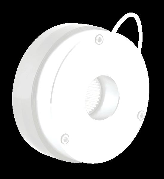
2 Spring actuated and electromagnetically released disk brake type powered by direct current. Designed for braking rotating machine parts and their precision positioning. Utilized as safety brake. High repeatability even with large number of actuations. The brake characterizes relatively simple construction, facility for regulating brake parameters such as braking torque, braking time and also possibility of supply from alternating current source after connecting up a rectifier circuit delivered at customer's request along with the brake. An additional feature is quiet operation, particularly important when the equipment is operated by a number of drives operating additionally with high frequency of actuations. Brake design guarantees simple and problem-free installation. Various options of executions are at disposal with respect to fittings/accessories, brake supply, climatic conditions of utilization, enabling selection of appropriate option for definite utilization conditions. They are designed for braking rotating parts of machines and their task is: emergency stopping, in order to ensure drive safety functions, immobilizing machine actuators, acting as a positioning device, minimizing run-on times of drives (to meed safety requirements according to Office of Technical Inspection (UDT) regulations, built onto an electric motor, the brake provides a self-braking motor, a drive unit meeting the requirements of utilisation safety and positioning. Brakes can be manufactured in variants suitable for various direct-current voltages: 24V, 104V, 180V, 207V which allows them to be supplied from standard alternating current sources, through appropriate rectifier. Brake type Parameters Unit Supply voltage Un [V] 24, 104, 180, , 104, 180 Power P20 [W] Braking torque Mh [Nm] Max. speed nmax min Weight G [kg] 0,5 0,7 1,8 3,2 3,2 6,6 7,5 11,2 17,0 24,8 29,0 80,0 120 Ambient temperature T 0 C Operating time * On direct voltage side On alternating voltage side t0, ms t0, t0,1 t0,9 ms Brake disconnection on alternating current side causes about five-times growth in braking time t 09 with respect to disconnection on direct current side t0,1 - releasing time (from switching on current to drop in braking torque to 10% Mnom) t0,9 - braking time (from switching off current to attaining 90% Mnom) *) Values of releasing and braking times are given as approximations, since they depend on mode of assembly/installation, temperature and power supply. Page 2 from 8 K-EN
3 Cable output: A 56, 100, 112, 132, 160, 180, 280, 315 B 63, 71, 80, 90, 200 A B Тype M h [Nm] D D1 D2 D3 D4 D5 D6 D7 D8 D9 L L1 L2 L3 L4 L5 L6 L7 K H H ,3x3 M4x , ,7 1,0 0, ,4 4,5x3 M4x , ,7 1,0 0, ,4 5,5x3 M5x ,7 1,0 0, ,4 6,4x3 M6x , ,0 1,0 0, ,4 6,4X3 M6X , ,0 1,0 0, ,4 6,4x3 M6x , ,0 1,0 0, ,3 8,4x3 M8x , ,0 2,0 0, ,4 8,4x3 M8x , ,0 2,0 0, ,8 9,0x4 M8x ,0 2,0 0, ,8 11x6 M10x ,0 2,0 0, ,8 11x6 M10x ,5 4, ,0 2,0 0, ,0 13x6 M12x ,0 3,0 0, ,0 13x6 M12x ,5 3,0 0, Geared bushing hole diameters Normalized hole diameter ranges Type d B T d max d smax * L , , , , , , ,3 35** ** 8 38,3 35** , , , , , Hole diameter B t 2 [mm] above - to , , , , , , , , , , , , ,4 d - standard geared bushing hole diameters d smax - maximum geared bushing hole diameters d* smax - at extra charge it is possible to manufacture the brakes with the specially increased diameter of the gear hub ** -for the 112 and 132 brakes and for the geared bushing hole diameters from 32 to 35mm, the key groove with the width of 8 mm (the width of the groove is incompatible with PN/M and DIN 6885 standards) K-EN Page 3 from 8
4 BEAKES EQUIPMENT Mounting flange Lever for manual release Brake cover IP56 brake cover Type L Lid Lid Lid with a hole Lid with a hole without a hole with a hole and a sealing ring and special packing ELECTRICAL EQUIPMENT A number of modules, ranging from simple circuits with classic designs, to complex assemblies ensuring quick action and drives positioning have been designed to drive the brakes. Relevant brake applications with switching in the primary or secondary circuits are ensured by half- or full-wave rectifiers and fast electronic circuits. The manufacturer recommends to use as low alternating current voltages as possible to supply the brakes. Appropriate choice of the control voltage will prevent or at least limit surges that may occur in power supply circuits. It is not recommended to use extensively long control wiring, which would be a source of harmful surges. Rectifier B2-1P The B2 1P rectifiers series forms a complete wave rectifier unit for direct installation. The terminal strip provided facilitates installation and connection to the circuit. Rectifier B2-1P cooperates with brakes (alternating voltage AC) Maximum output voltage (direct voltage DC) Maximum continuous output current rectifier RECTIFIER PARAMETERS B2-1P-400 B2-1P-600 UIN 400 VAC 600 VAC UOUT 0,45 UIN 0,45UIN IOUT 2A 2A For example (alternating voltage) - UIN = 230VAC, The resulting output voltage of the rectifier (direct voltage) - 0,45UIN= 0,45 x 230=104VDC Rectifier B5-1P The B5 1P rectifiers series forms a complete wave rectifier unit for direct installation. The terminal strip provided facilitates installation and connection to the circuit. Rectifier B5-1P cooperates with brakes (alternating voltage AC) Maximum output voltage (direct voltage DC) Maximum continuous output current rectifier RECTIFIER PARAMETERS B5-1P-400 B5-1P-600 UIN 400 VAC 600 VAC UOUT 0,45 UIN 0,45UIN IOUT 5A 5A For example (alternating voltage) - UIN = 230VAC, The resulting output voltage of the rectifier (direct voltage) - 0,45UIN= 0,45 x 230=104VDC Page 4 from 8 K-EN
5 Rectifier B2-2P The B2 2P rectifiers series forms a complete full-wave rectifier unit for direct installation. The terminal strip provided facilitates installation and connection to the circuit. The rectifier allows feeding input voltage max. 400VAC, 2A which after rectification provides DC voltage of value equal to 0,9 input voltage. Rectifier B2-2P cooperates with brakes RECTIFIER PARAMETERS (alternating voltage AC) U IN Maximum output voltage (direct voltage DC) U OUT Maximum continuous output current rectifier I OUT 250 VAC 0,9U IN 2A For example (alternating voltage) - UIN = 230VAC, The resulting output voltage of the rectifier (direct voltage) - 0,9UIN= 0,9 x 230=207VDC Rectifiers dimensions B2-1P-400, B5-1P-400, B2-2P B2-1P-600, B5-1P-600 Disconnection of power supply on AC side The diagram presents connection of rectifiers to supply circuit of motor. When disconnecting the voltage, the magnetic field causes the coil current to flow further through the rectifying diodes and drops slowly. The magnetic field reduces gradually causing prolonged time of braking action and consequently delayed increase of braking torque. If action time is irrelevant, brake should be connected on the AC side. When switching off, the supply circuits act as rectifying diodes. Disconnection of power supply on DC side The diagram presents connection of rectifiers into electric motor circuit. The coil current is interrupted between the coil and supply (rectifier) circuit. The magnetic field reduces very quickly, giving short time of braking action and consequently rapid growth of braking torque. When switching off on DC voltage side, a high peak voltage is generated in the coil causing faster wear of contacts due to sparking. For protecting the coil against peak voltages and protecting the contacts against excessive wear, the rectifier circuit is provided with protective facility allowing brake connection on DC voltage side. K-EN Page 5 from 8
6 Rectifier PS-1 Circuit PS-1 is built on the basis of MOSFET type semiconductor technique which enabled achieving effects not available in traditional designs. The brake electromagnet energized through circuit of this construction enables the brake to achieve connection and disconnection time parameters analogous to breaking of circuit on direct current side. The parameters obtained are not however gained through utilization of additional electrical circuits and switches. Simplicity of installation and parameters achieved enable very wide application, particularly in cases requiring positioning of drives, operation with high frequency of actuations compounded with repeatability of brake connecting and disconnecting times. Supply circuit PS-1 forms a complete unit for direct installation. Provided with a four-terminal strip, it enables unhindered adaptation in every cooperating circuit. The circuit is adapted for supply from alternating current source of VAC max. 420 VAC which after rectification and appropriate formation enables obtaining direct voltage of VDC for brake supply. The diagram below shows the method of connecting the circuit PS 1 into supply circuit of brake cooperating with 3x400 VAC electric motor with star-connected winding. Rectifier PS-1 cooperates with brakes Rectifier PS-2 Circuit PS-2 is built on the basis of MOSFET type semiconductor technique which enabled achieving effects not available in traditional designs. The brake electromagnet energized through circuit of this construction enables the brake to achieve connection and disconnection time parameters analogous to breaking of circuit on direct current side. The parameters obtained are not however gained through utilization of additional electrical circuits and switches. Simplicity of installation and parameters achieved enable very wide application, particularly in cases requiring positioning of drives, operation with high frequency of actuations compounded with repeatability of brake connecting and disconnecting times. Supply circuit PS 2 forms a complete unit for direct installation. Provided with a four-terminal strip, it enables unhindered adaptation in every cooperating circuit. The circuit is adapted for supply from alternating current source of VAC max. 250 VAC which after rectification and appropriate formation enables obtaining direct voltage of VDC for brake supply. The diagram below shows the method of connecting the circuit PS 2 into supply circuit of brake cooperating with 3x400 VAC electric motor with star-connected winding. Rectifier PS-2 cooperates with brakes Rectifiers PS-1, PS-2 dimensions Page 6 from 8 K-EN
7 CONTROL AND SIGNALING CIRCUTS microswitches Having in mind the user who requires the control of the brake, we have designed special signaling and control circuits, which enable to control the state of the brake (engaged, disengaged) and the wear of the plate lining. The usage of these circuits enables to control the brake with the use of automatic elements, which ensure high level of safety and reliability. Due to its compact design, the microswitch can be used in any other applications, as long as its parameters meet design requirements. MICROSWITCHES - ELECTRIC PARAMETERS Switch parameter Switch Switch KZ KO Max. voltage AC 250 V AC 250 V AC Max. AC switching current 5 A 6 A Max. Voltage DC 28V DC 220V DC 6A / 12V DC 3A / 24V DC Max. DC switching 3 A / 28V DC 1A / 60V DC current 0,5A / 110V DC 0,25A / 220V DC Protection rating IP 66 IP 66 Terminals NO /NC NO /NC Response monitoring microswitch KZ control of the state of brake (engaged, disengaged), MICROSWITCH DIMENSIONS Microswitch of the brake lining control KO the microswitch indicates approaching the maximum wear of the brake disc and the necessity of the brake s regulation or replacement of the disc brake, which enables further work of the brake. The regulation procedure is described in the brake operating manual. KO KZ Response monitoring microswitch and microswitch of the brake lining control KZ+KO Microswitches set KZ+KO is available from type 80 inclusive. SAMPLE INSTALATION PROCTECTIVE CIRCUITS thermal protection To protect electromagnet windings against heat build-up (slow-changing overloads) thermal sensor are used. In our offer we have PTC thermistors, which feature high resistance gradients when their rated temperature is reached - posistors - P or bimetallic thermal sensor - B. Posistor-based sensors are made in the form of an insulated pill with connecting wires extending inside a teflon insulation, installed directly on the electromagnet windings. Sensor circuit terminals are routed outside the brake to the terminal box and connected to a separate connection block or terminal strip. So-called resistance relays are intended for thermistorbased PTC temperature sensors. When temperature of at least one of the sensors rises above the rated value, the circuit resistance suddenly increases triggering the relay. Posistor thermal protection P Note! PTC sensor terminals must not be connected directly to the contactor. The brake protection has the form of a bimetallic sensor. Brake operation is controlled by a sensor or by a set of sensors, which ensure its safe operation; excessive temperature indication is obtained from the thermal switch installed inside the brake electromagnet's housing rated for a specific temperature. When the limit temperature for the sensor is exceeded, the information for the automatic control equipment is sent or the brake circuit is disconnected. Bimetallic thermal protection B AUXILIARY CIRCUITS anti-condensation heaters The so-called parking heating is used to prevent vapours condensation inside the brake. The equipment is particularly useful in negative temperatures or in high humidity environments. The heater is supplied through its dedicated pair of wires. The heater power supply voltage matches customer requirements. the need to define the voltage during order. Anti-condensation heaters GR - V SAMPLE INSTALATION K-EN Page 7 from 8
8 Page 8 from 8 K-EN VDC Nm d... MECHANICAL SIZE 56,63,71,80,90,100,112,132, 160,180,200,280,315 CONFIGURATION WITHOUT FITTING / ACCESORIES 1 LEVER FOR MANUAL RELEASE 2 DIAMETER OF SLEEVE GEAR d(h7) CLIMATIC VERSION ACCORDING TO STANDARDS: e.g. MT, TH MOUNTING FLANGE 3 NOMINAL BRAKING TORQUE [Nm] LEVER FOR MANUAL RELEASE + MOUNTING FLANGE 4 Execution options for the customer s request: - non-standard diameter of the sleeve gear brake d(h7) - equipped with heating elements in the winding (need to define the voltage supply) e.g. GR V - work at low temperatures C - Z - posistor thermal protection - P - bimetallic thermal protection - B - other voltage brake - response monitoring microswitch (engaged, disengaged) - KZ - microswitch of the brake lining control - KO - microswitches set - KZ+KO - increased durability of the brake, the brake is guaranteed lifetime 10x10 6 cycles - brake design allows for long-term and reliable operation T EXAMPLE: VDC 32Nm d25 GR110V VDC 12Nm d19 T VDC 60Nm d25 KZ+KO OPERATING VOLTAGE [V DC] 24, 104, 180, 207 PROTECTION RATING BASIC VERSION WITH HOLE D4 0 VERSION IP 54 - WITHOUT HOLE D4 1 VERSION IP 54 - WITH HOLE D4 + V-RING SEALING 2 VERSION IP 55 - WITHOUT HOLE D4 3 VERSION IP 55 - WITH HOLE D4 + V-RING SEALING 4 VERSION IP 56 - WITHOUT HOLE D4 + IP56 BRAKE COVER 5 VERSION IP 56 WITH HOLE D4 + SPECIAL SEALING + IP56 BRAKE COVER The producer reserves the right to modify as a result of developing the product. It is possible to realize special versions.
FACTORY OF ELECTRIC APPARATUS EMA ELFA
 FACTORY OF ELECTRIC APPARATUS EMA ELFA Sp. z o.o. st Pocztowa 7, 63-500 Ostrzeszów, PL phone: +48 62 730 30 51 fax: +48 62 730 33 06 handel@ema-elfa.pl www.ema-elfa.pl ELECTROMAGNETIC DISC BRAKES STE and
Modular Explosion Proof Brakes. IECLine rev 0
 Modular Explosion Proof Brakes IECLine 2013 rev 0 Application example Standard B5 motor + VIS brake Standard B5 motor + VIS brake + gearbox unit Main Characteristics -PATENT pending design and concept
Armature Actuated Brakes RoHS Compliant- meets the requirements of the Restriction of Hazardous Substances Directive
 RoHS Compliant meets the requirements of the Restriction of Hazardous Substances Directive DirectActing, DC brakes in torque ratings from 3 lbft to 300 lbft (4 Nm to 400 Nm) of torque. Dings Armature Actuated
D58 Series Brake Instructions
 D58 Series Brake Instructions 4740 W. Electric Avenue Milwaukee, WI 53219 414/672-7830 FAX 414/672-5354 www. dingsbrakes.com Safety information 2 Safety information 2.1 Persons responsible for the safety
Modular Flameproof Brakes
 Modular Flameproof Brakes New, Easy, Strong 2012 rev 0 INDEX PAG1 PAG2 PAG3 PAG4 PAG5 PAG6 PAG7 PAG8 PAG9-12 About VIS Application example, Main characteristics, Standards Certificates and available protection
Focus on Sci. & Tech. Grasp Details
 Focus on Sci. & Tech. Grasp Details B Series Safety brake, adopts modular design and has multiple functions, which can facilitate super rapid response with its professionally designed for low power electromagnetic
BRAKE MOTORS. 1. Brake motors TECHNICAL CATALOGUE. M Series / Standard / IEC
 1. Brake motors Standard motors (TS, TH, TP, D) can be constructed as brake motors (TBS, TBH, TBP, DB) when the driven machine must be stopped quickly and safely. This is done without modifying the motor
1. SPECIFICATION. Altitude of motor installation. Information: Resistance and temperature specifications of the PTC thermistor / posistor/.
 1. SPECIFICATION 5 GENERAL INFORMATION Motors with parameters according to the data sheet comply with the requirements of the IEC 60034-1 standard, and IEC 60034-30 class efficiency IE2 Motor versions:
your reliable partner ROBA-stop -M K.891.V17.EN
 ROBA-stop -M K.89.V7.EN www..com Your Reliable Brake Easy installation Class of insulation F; 00 % duty cycle C US Short switching times Different torque variants due to variable equipment Completely enclosed
Module 2 CONTROL SYSTEM COMPONENTS. Lecture - 4 RELAYS
 1 Module 2 CONTROL SYSTEM COMPONENTS Lecture - 4 RELAYS Shameer A Koya Introduction Relays are generally used to accept information from some form of sensing device and convert it into proper power level,
Holtumsweg 13, D Weeze, Tel /9134-0, Fax /1444
 Operation Instructions (translation) Explosion Protection Explosion protection is one option and is marked on the ex-type plate on the solenoid drive. The actuators and the associated solenoid controllers
Types of Motor Starters There are several types of motor starters. However, the two most basic types of these electrical devices are:
 Introduction Motor starters are one of the major inventions for motor control applications. As the name suggests, a starter is an electrical device which controls the electrical power for starting a motor.
Stromag Dessau. safety in motion PRODUCT CATALOGUE. NFF4F-LS Brake. for Slow-Running High Torque Drivelines, in harsh environment
 Stromag Dessau safety in motion PRODUCT CATALOGUE NFF4F-LS Brake for Slow-Running High Torque Drivelines, in harsh environment ENGINEERING THAT MOVES THE WORLD Applications Holding brake variations with
AF09... AF30 3-pole Contactors up to 20 HP / 480 VAC
 AF0... AF0 -pole Contactors up to 20 HP / 480 VAC Contactors and Overload Relays Overview...2 AF0... AF0 -pole Contactors Ordering Details...4 Main Technical Data...20 DC Circuit switching...2 Main Accessory
The galvanic separation of the primary or actuating circuit and the load circuits
 RELAY BASICS Relays are electro magnetically operated switches. An actuating current on a coil operates one or more galvanically separated contacts or load circuits. The electro mechanical relay is a remote
Installation and Operational Instructions for ROBA-stop Holding Brake Type _._
 Please read these Installation Instructions carefully and follow them accordingly! Ignoring these Instructions may lead to malfunctions or to brake failure, resulting in damage to other parts. Contents:
COMBIBOX. Program Schedule. Design. COMBIBOX clutch-brake-combination type 10 / 09 / 06. Attachments
 clutch-brake-combination 10 / 09 / 06 with an energised to engage single sided clutch / brake... 10 with an energised to engage single sided clutch without brake... 09 with an energised to engage single
Motor Controllers AC Semiconductor Motor Controller Type RSHP Flexy
 otor Controllers AC Semiconductor otor Controller Type RSHP Flexy Soft starting and stopping of 3-phase squirrel cage motors Low surge and vibration-free starting User-selected ramping profiles Integral
General Purpose Relay
 General Purpose Relay KML 15A switching capability 1.5kV dielectric strength (between coil and contacts) Various terminals available Socket available 1 to 3 pole configurations 1. COIL DATA (at 23 ) 1)
your reliable partner ROBA-stop K.800.V09.EN
 your reliable partner ROBA-stop K.800.V09.EN www..com your reliable partner Your Advantages When Using ROBA-stop ROBA-stop brakes attract customers because of their decided advantages in relation to operational
Focus on Sci. & Tech. Grasp Details
 Focus on Sci. & Tech. Grasp Details B Series Safety brake, adopts modular design and has multiple functions, which can facilitate super rapid response with its professionally designed for low power electromagnetic
setting the standard BFK468 spring-applied brake The Performance Standard 100-2,400 Nm
 setting the standard BFK468 spring-applied brake The Performance Standard 100-2,400 Nm www.intorq.de We set the standards The INTORQ brand stands for reliable brake solutions of the highest standard. Whether
TECHNICAL SPECIFICATION
 TECHNICAL SPECIFICATION Star/delta starter Description: The electromagnetic starters LT 3 Dxx series are devices designed for remote control, direct control and protection of induction motors coiled and
Introduction to Armature Actuated Brakes (AAB) Operating Principle. Engaged Condition (power off) Disengaged Condition (power on)
 Operating Principle. Engaged Condition (power off) Disengaged Condition (power on)") Introduction to Armature Actuated Brakes (AAB) The Armature Actuated Brakes are spring-set, electrically released, friction devices, which develop holding and braking torque in the absence of electrical
Introduction to Armature Actuated Brakes (AAB) The Armature Actuated Brakes are spring-set, electrically released, friction devices, which develop holding and braking torque in the absence of electrical
Control Circuit Protection
 Contents 5SJ4 Branch Circuit Protectors 5SY4 Supplementary Protectors 5SY6 Supplementary Protectors 16/19 5SJ4 Page Selection and ordering data 1-pole up to 63A 16/4 1-pole, 2-pole, 16/5 3-pole, 240VAC
HIGH POWER SOLENOID DRIVER 1
 Elactis SA Switzerland Phone : Fax : E-mail : Web : +41 22 364 65 85 +41 22 364 65 87 info@elactis.com http://www.elactis.com HIGH POWER SOLENOID DRIVER 1 ADRV1012K 1 This datasheet is a preliminary description.
Power Electronics. MINISTOP Motor Brake Relay BA 9034N
 Power Electronics IISTOP otor Brake Relay BA 9034 0256981 Your advantages Higher safety level and more economic by short stopping cycle Cost saving Compact design Easily appliance, no need for current
Steering column and sensor
 Steering column and sensor Type LAB Series 1 x Nominal voltage 12 to 48 volt Output signal digital, analog and direction (option) HE 11874 / 09.2017 2 LAB HE 11874 / 09.2017 Page Content 4 4 5 6 7 7 8
W22 Brake Motor Three-phase Electric Motor
 Motors Automation Energy Transmission & Distribution Coatings W22 Brake Motor Three-phase Electric Motor African Market -- Visual index Main motor parts 1 Sealing system 8 Fan 2 Endshields 9 Bridge rectifier
MADE IN GERMANY. Electromagnetic Technology
 MT MADE IN GERMANY Electromagnetic Technology KEB Automation KG 2 MAGNETTECHNIQUE All our efforts are directed towards the development, production and application of electromagnetic technology throughout
your reliable partner ROBA-stop -M Electromagnetic safety brakes C US LR K.891.V16.EN
 ROBA-stop -M Electromagnetic safety brakes C US LR 0897 K.89.V6.EN www..com Your Reliable Brake Easy installation Class of insulation F; 00 % duty cycle C US Short switching times Different torque variants
Installation and Operational Instructions for ROBA-stop -tacho brake Type 83_.41_._ and ROBA-stop -tacho peak load brake Type _.
 Please read the Operational Instructions carefully and follow them accordingly! Ignoring these Instructions may lead to malfunctions or to brake failure, resulting in damage to other parts. Contents: Page
Linear Motors & Servo Drives 3x400VAC. Linear Motor Series P The linear motor technology for industrial applications. Peak force up to 2 500N
 Linear Motors & Servo Drives 3x400VAC Linear Motor Series P10- Peak force up to 2 500N Velocity up to 5m/s Acceleration up to 100g Free positioning Long life: Linear direct drive The linear motor technology
COMBIBOX Program Schedule. Design. COMBIBOX Clutch-brake-combination type 10 / 09 / 06. Attachments input
 COMBIBOX Program Schedule COMBIBOX Clutch-brake-combination type 10 / 09 / 06 with an energised to engage single sided clutch / brake COMBIBOX 10 page 37 with an energised to engage single sided clutch
KEB-sähkömagneettiset jarrut ja kytkimet
 Solutions for power transmission KEB-sähkömagneettiset jarrut ja kytkimet www.konaflex.fi MAGNET TECHNOLOGY EN KEB AUTOMATION KG All our efforts are directed towards the development, production and application
COMPONENTS. Off-load Switch for Fixed Installation Title type SW
 COMPONENTS Off-load Switch for Fixed Installation Title type SW General information The SW off-load switch is a complete range designed to cover all the applications to be met in DC traction power substations
TeSys contactors. Use in category DC-1 (resistive loads; time constant L/R y 1 ms) Rated operational current Ie. to be wired in series
 Rated operational current Ie. to be wired in series") Selection 3-pole shockproof contactors FG d.c. supply Selection guide for utilisation categories DC-1 to DC-5 Use in category DC-1 (resistive loads; time constant L/R y 1 ms) Rated operational current
Selection 3-pole shockproof contactors FG d.c. supply Selection guide for utilisation categories DC-1 to DC-5 Use in category DC-1 (resistive loads; time constant L/R y 1 ms) Rated operational current
Question Number: 1. (a)
") Session: Summer 2008 Page: 1of 8 Question Number: 1 (a) A single winding machine cannot generate starting torque. During starting the switch connects the starting winding via the capacitor. The capacitor
Session: Summer 2008 Page: 1of 8 Question Number: 1 (a) A single winding machine cannot generate starting torque. During starting the switch connects the starting winding via the capacitor. The capacitor
Copeland Screw Compressors Semi-Hermetic Compact Operating Instructions
 Copeland Screw Compressors Semi-Hermetic Compact Operating Instructions SCH2 & SCA2 High Temperature Compressors 35-240 Horsepower 1. Introduction This series of semi-hermetic compact screw compressors
Exercise 1-5. Current Protection Devices EXERCISE OBJECTIVE DISCUSSION OUTLINE DISCUSSION. Circuit breakers
 Exercise 1-5 Current Protection Devices EXERCISE OBJECTIVE Describe and test the operation of circuit breakers, fuses, and overload relays. DISCUSSION OUTLINE The Discussion of this exercise covers the
QuarryMaster. Helical-Bevel Geared Motors
 QuarryMaster Helical-Bevel Geared Motors It runs and runs and runs and runs... Are you unearthing large quantities on an ongoing basis? Do you sometimes move huge masses? Standstill is not part of your
INDUSTRIAL POWER SUPPLIES SFL-SERIES
 INDUSTRIAL POWER SUPPLIES SFL-SERIES Operating Instructions 1. Application The SFL-series are compact, rugged switching power supplies designed for applications in process automation and other industrial
Compact electric actuators for 90 operation of 1/4 turn valves providing a range of torque outputs up to 1645 Nm.
 Compact electric actuators for 90 operation of 1/4 turn valves providing a range of torque outputs up to 1645 Nm. Features Gearcasing and enclosure is ESPC coated anodised aluminium, except Model 003 which
TAE pole Contactors
 TAE9...26 3-pole Contactors d.c. operated with double-winding coil SB8033C3 Utilisation TAE9 to TAE26 contactors are a compliment to the DC control contactor range. The coils have large voltage ranges
Solenoid System FLANGE MOUNTING VERSION
 EVI 9S Solenoid System COIL The EVI 9S system by AMISCO includes a wide range of solenoid operators designed for pneumatic valves. All solenoids of this system have the guide tube with a diameter of 8
Power Electronics. Motor brake relay GA 9031 ministop
 Power Electronics Motor brake relay GA 90 ministop 0 Thyristor electronic brake relay for motors up to kw Adjustable braking current up to 0 A Adjustable braking time Automatic standstill monitoring (optional)
Electronic Ballast EVG 2000-T
 Electronic Ballast EVG 2000-T Operating Manual Table of contents 1 Description 1.1 Advantages of this ballast... 3 1.2 Functional principle... 3 1.3 Energization... 4 1.4 Visualization... 5 1.5 Indications
Motor Controllers AC Semiconductor Motor Controller Type RSHP Flexy
 Controllers AC Semiconductor Controller Type Soft starting and stopping of -phase induction squirrel cage motors Low inrush and reduced vibration during starting User-selected ramping profiles Integral
Catalog Mars Low voltage Brake motors
 Catalog Mars 2014 Low voltage Brake motors We provide motors, generators and mechanical power transmission products, services and expertise to save energy and improve customers processes over the total
BETA Switching Switches and Light Indicators
 Siemens AG 2008 BETA Switching /2 Product overview /3 5TE8 control switches / 5TE4 pushbuttons /2 5TE5 light indicators /5 5TE8 ON/OFF switches /22 5TE9 busbars /24 5TE switch disconnectors Siemens ET
Electromagnetically actuated clutches and brakes
 Electromagnetically actuated clutches and brakes General notes Dry-running/wet-running 4.03.00 Electrical circuits 4.03.00 Rectifier units 4.03.00 Coil connections 4.04.00 Spark quenching 4.04.00 Protection
Directional servo-valve of 4-way design
 Courtesy of CM/Flodyne/Hydradyne Motion Control Hydraulic Pneumatic Electrical Mechanical (0) 426-54 www.cmafh.com Directional servo-valve of 4-way design Type 4WSE3E 32 Size 32 Component series 5X Maximum
champion series motors
 Introducing A brand new series of Super Performers Data Sheet champion series motors FRAME SIZE 63-132M TEFC 3 Phase Squirrel Cage Induction Motors Siemens CHAMPION Series Cage Motors are suitable for
P2050S-030, 1/2, Electronic Pressure Independent Valve Stainless Steel Ball and Stem, Female NPT Ends
 P2050S-030, 1/2, Electronic Pressure Independent Valve Stainless Steel Ball and Stem, Female NPT Ends Application Water-side control of heating and cooling systems for AHUs and water coils. Equal Percentage/
S10010 / S SPRING RETURN DIRECT-COUPLED DAMPER ACTUATORS 10/20 Nm (88/177 lb-in) FOR MODULATING AND FLOATING CONTROL SPECIFICATIONS GENERAL
 FOR MODULATING AND FLOATING CONTROL SPECIFICATIONS GENERAL") S000 / S000 SPRING RETURN DIRECT-COUPLED DAMPER ACTUATORS 0/0 Nm (88/77 lb-in) FOR MODULATING AND FLOATING CONTROL GENERAL These direct-coupled damper actuators provide modulating / floating control for:
S000 / S000 SPRING RETURN DIRECT-COUPLED DAMPER ACTUATORS 0/0 Nm (88/77 lb-in) FOR MODULATING AND FLOATING CONTROL GENERAL These direct-coupled damper actuators provide modulating / floating control for:
POWER TRANSMISSION. Product range
 POWER TRANSMISSION Product range Product range Business Unit Power Transmission Since the firm was established in 1911 by Wilhelm Binder, the Power of Magnetism has always been the essential principle
TYPE 2 poles 4 poles 6 poles 8 poles 2 / 4 poles 4 / 8 poles 2 / 8 poles 4 / 16 poles
 BAH-BAHS series Overwiew MGM Electric Motors was established in 1950 as a brake motors manufacturer. MGM is today a world leading manufacturer of this line of products. MGM brake motors are designed and
to move Electric Roller Screw Servo Actuators for Spot Welding
 Engineered to move Electric Roller Screw Servo Actuators for Spot Welding INDUSTRIAL ROLLER SCREW SERVO ACTUATORS Strong, Consistent Force for Maximum Productivity and Weld Quality Diakont delivers the
Short form catalogue. Motor protection & control
 Short form catalogue Star Series Motor protection & control Motor Protection and Control up to 25 HP / 600 VAC Overview...2 Contactors and Overload Relays...11 4-pole Contactors...41 Control Relays...59
COMBIBOX. Program Schedule. with an energised to engage single sided clutch without brake... COMBIBOX 09
 COMBIBOX clutch-brake-combination 10 / 09 / 06 with an energised to engage single sided clutch / brake... COMBIBOX 10 with an energised to engage single sided clutch without brake... COMBIBOX 09 with an
INSTALLATION INSTRUCTIONS FOR SYMCOM'S MODEL 777-HVR-SP ELECTRONIC OVERLOAD RELAY
 CONNECTIONS INSTALLATION INSTRUCTIONS FOR SYMCOM'S MODEL 777-HVR-SP ELECTRONIC OVERLOAD RELAY BE SURE POWER IS DISCONNECTED PRIOR TO INSTALLATION!! FOLLOW NATIONAL, STATE AND LOCAL CODES! READ THESE INSTRUCTIONS
Electronic Circuit Breaker ESS20-0..
 Electronic Circuit Breaker ES-0.. Description Electronic circuit breaker type ES-0.. is designed to ensure selective disconnection of individual loads in systems which are powered by a DC 4 V switch-mode
Direct On Line (DOL) Motor Starter. Direct Online Motor Starter
 Motor Starter. Direct Online Motor Starter") Direct On Line (DOL) Motor Starter Direct Online Motor Starter Different starting methods are employed for starting induction motors because Induction Motor draws more starting current during starting.
Direct On Line (DOL) Motor Starter Direct Online Motor Starter Different starting methods are employed for starting induction motors because Induction Motor draws more starting current during starting.
DISTRIBUTION SOLUTIONS. GSec Gas-insulated switching and isolating apparatus
 DISTRIBUTION SOLUTIONS GSec Gas-insulated switching and isolating apparatus GSec is a three-position SF6 gas-insulated switchdisconnector designed for use in medium voltage switchgear for secondary distribution
Electromagnetic clutches and brakes INTORQ and INTORQ
 Electromagnetic clutches and brakes INTORQ 14.105 and INTORQ 14.115 7.5 480 Nm setting the standard Product information INTORQ electromagnetic clutches and brakes transmit the drive torque or braking torque
Motor Controllers Soft Starting/Soft Stopping Types RSC 4.../RSO 12.., RSC 60.../RSO 16..
 otor Controllers Soft Starting/Soft Stopping Types RSC 4..../RSO 12.., RSC 60.../RSO 16.. Control and output modules for soft starting/stopping of 3-phase induction motors Rated operational current: 3
AF series contactors (9 2650)
") R E32527 R E39322 contactors General purpose and motor applications AF series contactors (9 2650) 3- & 4-pole contactors General purpose up to 2700 A Motor applications up to 50 hp, 900 kw NEMA Sizes 00
R E32527 R E39322 contactors General purpose and motor applications AF series contactors (9 2650) 3- & 4-pole contactors General purpose up to 2700 A Motor applications up to 50 hp, 900 kw NEMA Sizes 00
S1024-2POS / S POS S2024-2POS / S POS
 GENERAL S0-POS / S00-POS S0-POS / S00-POS SPRING RETURN DIRECT-COUPLED DAMPER ACTUATORS 0/0 Nm (88/77 lb-in) FOR -POSITION CONTROL These direct-coupled damper actuators provide two-position control for:
Module B Module C FOR THE WEATHER CONTROLLER MULTI-MIX INSTALLATION MANUAL REVISION: 1.0_EN
 Module B Module C FOR THE WEATHER CONTROLLER MULTI-MIX INSTALLATION MANUAL REVISION: 1.0_EN 05-2018 ELECTRIC DEVICE UNDER VOLTAGE! Before any action related to the power supply (cables connection, device
Control Relays Overview
 Control Relays Overview DESIGN FEATURES Among the advances Agastat Control Relays offer over existing designs is a unique contact operating mechanism. An articulated arm assembly amplifies the movement
COMBISTOP NEW. Spring applied brakes
 COMBISTOP NEW Spring applied brakes With manufacturing sites on three continents and a global sales network KEB ensures worldwide availability and support of the KEB COMBISTOP 38. This latest generation
MB A 12V/24V DC PROGRAMMABLE DUAL BATTERY ISOLATOR
 MB-3688 120A 12V/24V DC PROGRAMMABLE DUAL BATTERY ISOLATOR User Manual Warning and Precautions MB-3688 is built with corrosion resistant material and the main electronic assembly is well sealed inside
APPLICATION GUIDE. Pure easiness for a wide range of applications ACS580 general purpose drives
 APPLICATION GUIDE Pure easiness for a wide range of applications ACS580 general purpose drives 2 APPLICATION GUIDE ACS580 PURE EASINESS FOR MANY PURPOSES Table of contents 3 Pure easiness for many applications
SEW Brakes. Service and Maintenance
 SEW Brakes Service and Maintenance Objectives Upon completion of this presentation, you will be able to accomplish the following - Describe the purpose of the SEW brake - Explain the operation of the SEW
Brakes ELECTROMAGNETIC. KNOTT Electromagnetic Single Disc Brakes TYPE EAA, EAR
 Brakes ELECTROMAGNETIC KNOTT Electromagnetic Single Disc Brakes TYPE EAA, EAR www.knott.de We make your brake KNOTT Electromagnetic Single Disc Brakes TYPE EAA, EAR 1 KNOTT manufacture a wide range of
Solenoid drive. Operating instructions
 Operating instructions (translation) Explosion protection The explosion protection is an option and is indicated by an Ex type plate on the solenoid actuator. The solenoid actuators and integrated solenoid
MADE IN GERMANY. Electromagnetic Technology
 MADE IN GERMANY MT Electromagnetic Technology Safe braking and holding COMBISTOP H COMBISTOP D COMBISTOP T COMBISTOP Electromagnetically actuated dual-surface spring applied DC brakes for dry operation.
Spring-applied single-disc brake. Operating Instructions A00 CLASSIC LINE
 CLASSIC LINE Operating Instructions 77 600..A00 Spring-applied single-disc brake Types: 77 60010A00 77 60011A00 77 60013A00 77 60016A00 77 60019A00 77 60024A00 Contents 1. General information... 3 1.1
MAKING MODERN LIVING POSSIBLE. Pressure switch BCP. Technical brochure
 MAKING MODERN LIVING POSSIBLE Pressure switch BCP Technical brochure Contents Page Pressure switch, BCP Introduction...............................................................................3 Features...................................................................................3
Oil/Air Cooler Units
 COMPLETE OIL / AIR COOLER SYSTEM WITH AXIAL FAN FOR INDUSTRIAL APPLICATIONS. General description In hydraulic systems energy is transformed and transmitted. During this process, efficiency losses occur,
FLAT/VERTICAL TYPE HIGH POWER BIFURCATED CONTACT
 FLAT/VERTICAL TYPE HIGH POWER BIFURCATED CONTACT NC NC RELAYS Flat type Flat type (PC board) (PC board) FEATURES 1. Compact, slim design Use of high-performance flat electromagnetic design achieves 10.9
Aldi V4 & V V1.1 5/23/2014
 Aldi V4 & V5 2012 2013 V1.1 5/23/2014 Aldi Control Techniques SK Series VFD & Hussmann MX Series MicroChannel Condenser Equipment Operation Component Orientation Control Wiring Programming and Start Up
SUBSTATION VACUUM CIRCUIT BREAKER (15.5KV)
") SUBSTATION VACUUM CIRCUIT BREAKER (15.5KV) For more than four decades, Myers Power Products has led the switchgear market in quality for the electric industry, delivering highly reliable products for utilities
SUBSTATION VACUUM CIRCUIT BREAKER (15.5KV) For more than four decades, Myers Power Products has led the switchgear market in quality for the electric industry, delivering highly reliable products for utilities
SUBSTATION VACUUM CIRCUIT BREAKER (38KV)
") SUBSTATION VACUUM CIRCUIT BREAKER (38KV) For more than four decades, Myers Power Products has led the switchgear market in quality for the electric industry, delivering highly reliable products for utilities
SUBSTATION VACUUM CIRCUIT BREAKER (38KV) For more than four decades, Myers Power Products has led the switchgear market in quality for the electric industry, delivering highly reliable products for utilities
SUBSTATION VACUUM CIRCUIT BREAKER (25.8 / 27KV)
") SUBSTATION VACUUM CIRCUIT BREAKER (25.8 / 27KV) For more than four decades, Myers Power Products has led the switchgear market in quality for the electric industry, delivering highly reliable products
SUBSTATION VACUUM CIRCUIT BREAKER (25.8 / 27KV) For more than four decades, Myers Power Products has led the switchgear market in quality for the electric industry, delivering highly reliable products
ACCESSORY KIT INSTALLATION INSTRUCTIONS
 ACCESSORY KIT INSTALLATION INSTRUCTIONS Low Ambient Accessory For Air Cooled Split-System Air Conditioners YD360/480/600, YJ-30/-40/-50 and J30/40/50 YD Models 642546-UAI-A-080 GENERAL Standard operation
SNAP ACTION SWITCHES type SAS-00, SAS-03
 EN 60947-5- SNAP ACTION SWITCHES type SAS-00, SAS-03 SAS 00 and 03 Series snap-action switches have one NO and one NC contacts. The change of the switching position is realized by the mechanism, which
3RT14 Contactors with 3 Main Contacts
 3RT14 Contactors with 3 Main Contacts for Switching Resistive Loads Contactor Size 3RT14 46 Mechanical endurance Oper. 10 million Electrical endurance Oper. 0.5 million C-1 utilization category at I e
KD LV Motor Protection Relay
 1. Protection Features KD LV Motor Protection Relay Overload (for both cyclic and sustained overload conditions) Locked rotor by vectorial stall Running stall / jam Single phasing / Unbalance Earth leakage
AF09... AF38 4-pole Contactors AC / DC Operated - with Screw Terminals
 AF09... AF38 4-pole Contactors AC / DC Operated - with Screw Terminals 25 to 55 A culus CE Application AF09... AF38 4-pole contactors are used for controlling power circuits up to 600 V AC and 240 V DC.
Installation Contactors RIC, RAC
 Installation Contactors RIC, RAC 1 Characteristics Rated operational current: 20 63 A Coil voltages: UC 24, 36, 230 V / AC 400 V Hum-free (UC versions) 2 4 contacts NC or NO Extendable with auxiliary contacts
Ktec Contactors and thermal overloads
 Contactors and thermal overloads Techna KTEC series contactors provide a complete solution for your ac contactor requirements.the range carries TUV, UL & CSA certification, for use in Europe, North America
Ordering Information. Switching Power Supply S82F. Industrial-Grade Power Supply for General or Peak Load Applications SWITCHING POWER SUPPLIES
 Switching Power Supply S82F Industrial-Grade Power Supply for General or Peak Load Applications Correct input voltage range is automatically selected: 1 VAC or 2 VAC. Model S82F-P is suitable for peak
Description. Positive safety relays
 Type N & KC Positive safety Description A.C. or D.C. operated DIN rail or panel mounting 600 volt heavy duty design, A600-10 amp, Q300-5 amp Snap-on accessories available: 1 & 4 pole adder deck Pneumatic
AC Rectifiers for use with Armature Actuated Brakes. Product Overview. Full Wave. Half Wave. Combination Full and Half Wave. TOR-AC Full and Half Wave
 Rectifiers for use with Armature Actuated Brakes Product Overview NOTE: For brake response times with and without rectifiers see page 94. Full Wave A rectifier in which both positive and negative half-cycles
Industrial Relay KML(1C, 2C)
") Industrial Relay KML(1C, 2C) Features 1C: 15A, 2C: 10A switching capability 1.5kV dielectric strength (between coil and contacts) Various terminals available Socket available 1 & 2 poles configurations
Industrial Relay KML(1C, 2C) Features 1C: 15A, 2C: 10A switching capability 1.5kV dielectric strength (between coil and contacts) Various terminals available Socket available 1 & 2 poles configurations
Please read these Operational Instructions carefully and follow them accordingly!
 Please read these Operational Instructions carefully and follow them accordingly! Ignoring these Instructions may lead to malfunctions or to brake failure, resulting in damage to other parts. These Installation
DEEP SEA ELECTRONICS PLC
 COMPLEX SOLUTIONS MADE SIMPLE DEEP SEA ELECTRONICS PLC DSE704 AUTOSTART CONTROL MODULE OPERATING MANUAL 057-042 704 Operating Instructions Issue 2.1 18/06/2007 11:27:00 JR - 1 - Deep Sea Electronics Plc
Instructions Contact numbers to EN Coil terminal markings to EN Integrated diode-resistor combination Coil rating 2.
 Deliveryprogram Contactorrelay,2N/O+2N/C,DCcurrent Partno. DILER-22-G(220VDC) Articleno. 010091 CatalogNo. XTRM10A22BD Product range DILER Mini-contactors Application Contactor relays Description with
AF series contactors (9 2650)
") R E32527 R E39322 contactors General purpose and motor applications AF series contactors (9 2650) 3- & 4-pole contactors General purpose up to 2700 A Motor applications up to 50 hp, 900 kw NEMA Sizes 00
R E32527 R E39322 contactors General purpose and motor applications AF series contactors (9 2650) 3- & 4-pole contactors General purpose up to 2700 A Motor applications up to 50 hp, 900 kw NEMA Sizes 00