The galvanic separation of the primary or actuating circuit and the load circuits
|
|
|
- Barrie Woods
- 5 years ago
- Views:
Transcription

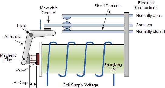
1 RELAY BASICS Relays are electro magnetically operated switches. An actuating current on a coil operates one or more galvanically separated contacts or load circuits. The electro mechanical relay is a remote controlled switch capable of switching multiple circuits, either individually, simultaneously, or in sequence. The primary functions of a relay are: The galvanic separation of the primary or actuating circuit and the load circuits Single input/multiple output capability Separation of different load circuits for multi-pole relays Separation of AC and DC circuits Interface between electronic and power circuits Multiple switching functions, e.g. delay, signal conditioning Amplifier Applications of a Relay Typical applications for relays include laboratory instruments, telecommunication systems, computer interfaces, domestic appliances, air conditioning and heating, automotive electrics, traffic control, lighting control, building control, electric power control, business machines, control of motors and solenoids, tooling machines, production and test equipment. Electromechanical Relays Electromechanical relays are those where the switching element is a mechanical contact, actuated by an electromagnet. This is the most widely used type of relay design. The principal internal functions of an electromechanical relay are: 1. Conversion of electrical current (input, coil current) to a magnetic field 2. Conversion of the magnetic field into a mechanical force 3. This force operates the contacts (secondary side) 4. Contacts switch and conduct electrical current (output, load current) 1
2 Electromechanical Relay Design The most important components are: Magnetic system (or primary section) Coil (to generate the necessary magnetic field to actuate the armature and the contacts) Core (highly magnetic permeable - concentrates the magnetic field) Yoke (to establish the magnetic circuit) Armature (the moving part of the magnetic system which closes and opens the magnetic circuit and acts via an actuator or the moving relay contacts) Return spring (For quick return of the moving contact to normal condition on removal of the coil power) Contact system (or secondary section) Fixed contacts Moving contacts (contacts being moved by the magnetic system to switch the load circuit) Contact springs (holding the contacts but sufficiently flexible to allow the contacts to move) Mechanical components Case & Base (to protect the relay against external influences and for protection against electric shock) Insulation within the relay to separate the primary circuit from the secondary side and to provide the required Actuator (used in some relay designs to translate the motion of the magnetic system to the contact system) Moving contacts must have insulation properties to isolate the primary circuit (coil, magnetic circuit) from the secondary side (contact system) Pins or terminals to connect between the contact system and the load Mounting devices such as sockets, solder hooks, PCB pins, brackets, captive screws 2
3 Basic Relay Terminologies AC Coil: Relays for direct energization with AC supply. Unless otherwise specified, AC coils may be used with 50Hz supply. Ambient Temperature: Temperature measured directly near the relay. The maximum allowed value may not be exceeded; otherwise there is a chance for relay failure. (e.g. Coil overheating) Bounce Time: Time interval between the first and final closing (or opening) of a contact, caused by a mechanical shock process in contact movement. These shock processes are called contact bounce. Break Contact: A contact that is closed in the rest state of the relay and open in the operating state. Bridging Contact: A special contact assembly consisting of two stationary contacts that are connected by a movable bridge. When in open contact the bridge is separated on both sides from the stationary contacts. Due to this double interruption a bigger contact gap can be achieved. This is of advantage especially at very high contact loads or when there are safety requirements. Change Over Contact: Compound contact consisting of a make contact and a break contact with a common contact spring. When one contact circuit is open the other one is closed. Coil Current: The current (by design) drawn by the coil to generate the magnetic pull force. The moment the coil is switched to On, the current is higher than in continuous use. Coil Resistance: Electrical resistance of the relay coil at reference temperature. The coil resistance varies with temperature. Contact Forms: This denotes the contact mechanism and the number of contacts in the circuit. Form A contacts are also called NO (Normally Open) contacts or make contacts. Form B contacts are also called NC (Normally Closed) contacts or break contacts. Form C contacts are also called Changeover contacts. Contact Gap: Distance between the contacts in the open contact circuit. Contact Rating: The current a relay can switch On and Off within specified conditions. Contact Resistance: The electrical resistance of a closed contact circuit, measured at the terminals of the relay within specified parameters. Creepage Distance: Closest distance between two conductive parts, measured along the surface of insulated parts. Dielectric Strength: The voltage the insulation can withstand between relay elements that are insulated from one another. Driver Protection circuit: When the coil energization is switched off, a very high negative peak voltage is produced by the coil that may reach more than times the nominal coil voltage. This can damage the coil. A solution is provided by a driver protection circuit that is a damping component, which is connected in parallel to the coil. This protects the driver but slows the release time of the relay. Also known as the coil snubber circuit or suppressed coil. Dropout Voltage: The Voltage at or below which all the contacts of an operated relay must revert to unoperated position. Also known as release voltage. 3
4 Dust Proof Relays / Solder Proof Relay: Relay with a case for protection against dust and touch. If specified solder conditions are kept, no harmful amounts of flux or solder vapor can penetrate inside the relay. Electrical Endurance (Electrical Life): Number of operations until switching failure of a relay under defined conditions of load and of ambient. The specified reference values for the life of the relay apply, within a resistive load window. At lower contact loads a substantially longer electrical life is achieved. At higher loads the electrical life is reduced substantially. Hermetically Sealed Relays: Relay that is has a metal case, its connecting pins are sealed with glass it then fulfils highest requirements regarding sealing. lnrush Current: This value specifies the instantaneous current that may flow under defined conditions. Insulation Resistance: Electrical resistance, measured between insulated relay parts at a specified test voltage. Make Contact: A contact that is open in the rest state and closed in the operating state. Material Transfer: During the switching procedure the arc heats up the two contacts differently, depending on the load and polarity. This will result in material transfer from the hotter electrode to the cooler electrode. With higher DC loads on the contact a pip is built up, the other contact loses material and it creates a crater. Maximum Carrying Current: The maximum current the contacts can safely pass without being subject to temperature rise in excess of their design limit. Maximum Continuous Voltage: The maximum voltage that can be applied to the relay coil uninterruptedly without causing damage. Maximum Switching Current: The maximum current that can safely be switched by the contacts. Maximum Switching frequency: The maximum switching frequency which satisfies the mechanical or electrical life under repeated operations by applying a pulse train at the rated voltage to the operating coil Maximum Switching Power: The maximum value that can be switched by the contacts without causing damage. Maximum Switching Voltage: The maximum open circuit voltage that can be safely switched by the contacts. Mechanical Endurance (Mechanical Life): Number of switching operations, without contact load, the relay can operate whilst remaining within the specified characteristics. Mechanical Flag Indication: Mechanical indicator in relays (mostly industrial relays) which is linked to the contacts and shows their position. Nominal Coil Power: Power consumption of the coil at nominal voltage and nominal coil resistance. Also known as Rated Power. Nominal Coil Voltage: The voltage designed to operate the relay coil. Also known as Rated Voltage. Open Relay: Relay without case or cover. Operating Power: Rated power at which the relay operates 4
5 Operate time: The time from the initial application of power to the coil until the closure of the normally open contacts. Excluding bounce time. PCB Relays: Relays designed for soldering directly into printed circuit boards. Pick-up Voltage: The value of the voltage that should be applied to an un-operated relay coil at or above which all the contacts of the relay should operate. Also known as Pull-in voltage / Must operate voltage. Plug-in Relay: Relays with socket pins. Release Time: The time from the disconnection of the coil until the re-closure of the normally closed contacts. Excludes bounce time. Shock Resistance: lt specifies the mechanical shock the closed contact can resist or no damage occurs. (multiple of gravitational acceleration in measured in g s within a set duration in ms) Test Button: button (usually in industrial relays), which is accessible from the outside. Typically it manually switches the contact circuit of a de-energized relay from Off to On condition. Vibration Resistance: specifies the amplitude or the acceleration up to a defined frequency range for which the contacts are rated to operate without failure. 5
6 6
7 NOTES 7
8 This document is not intended as a comprehensive guide and the information provided should generally be treated as illustrative. Any changes or proposed alterations are welcome. 8
Control Relays Overview
 Control Relays Overview DESIGN FEATURES Among the advances Agastat Control Relays offer over existing designs is a unique contact operating mechanism. An articulated arm assembly amplifies the movement
Electro - Hydraulics. & Pneumatics. Electro Hydraulic Press. Comparison. Electro Hydraulics. By: Alireza Safikhani
 Electro - 9 Hydraulics & Pneumatics 2 Electro Hydraulic Press The hydraulic press is controlled via the electrical control panel. Electrical signals are used to activate the valves in the hydraulic installation.
Module 2 CONTROL SYSTEM COMPONENTS. Lecture - 4 RELAYS
 1 Module 2 CONTROL SYSTEM COMPONENTS Lecture - 4 RELAYS Shameer A Koya Introduction Relays are generally used to accept information from some form of sensing device and convert it into proper power level,
MERCURY CONTACTORS & RELAYS
 MERCURY CONTACTORS & RELAYS PHONE: 704-399-4248 FAX: 704-399-4167 WWW.SETHERMAL.COM INDEX GLOSSARYOFTERMS&EXPRESSIONS...1 GENERALINFORMATIONFEATURES&SELECTIONFACTORS...13 MERCURY TO METAL CONTACTORS AND
Push buttons are of two types i) Momentary push button ii) Maintained contact or detent push button
 Momentary push button ii) Maintained contact or detent push button") ELECTRO-PNEUMATIC Push button switches A push button is a switch used to close or open an electric control circuit. They are primarily used for starting and stopping of operation of machinery. This causes
ELECTRO-PNEUMATIC Push button switches A push button is a switch used to close or open an electric control circuit. They are primarily used for starting and stopping of operation of machinery. This causes
Twin coil relays TCR and TCR-F. Chassis Systems. Conditions
 Powertrain Systems Chassis Systems Safety Security Body Driver Information Convenience Features - Special relay for motor polarity reversal - Optimized assembly - High switching capacity Typical applications
MAGNETIC MOTOR STARTERS
 Chapter 6 MAGNETIC MOTOR STARTERS 1 The basic use for the magnetic contactor is for switching power in resistance heating elements, lighting, magnetic brakes, or heavy industrial solenoids. Contactors
1.0 Installation Wiring
 1.0 Installation Wiring DX Firebox is designed to be an electronic replacement for Pontiac & Ford buzz coils when operated on DC. Installation may be positive or negative ground. Simply observe the RED
AF series contactors (9 2650)
") R E32527 R E39322 contactors General purpose and motor applications AF series contactors (9 2650) 3- & 4-pole contactors General purpose up to 2700 A Motor applications up to 50 hp, 900 kw NEMA Sizes 00
R E32527 R E39322 contactors General purpose and motor applications AF series contactors (9 2650) 3- & 4-pole contactors General purpose up to 2700 A Motor applications up to 50 hp, 900 kw NEMA Sizes 00
40 Series - Miniature PCB relays A. Features
 1. = 12.4 1. = 12.4 1. = 12.4 40 Series - Miniature PCB relays 8-10 - 16 A Features 40.31 40.1 40.2 1 & 2 Pole relay range 40.31-1 Pole 10 A (3. mm pin pitch) 40.1-1 Pole 10 A ( mm pin pitch) 40.2-2 Pole
Scheda prodotto Relè Series E
 Relè Miniatura All-or-Nothing relays ideally suited for any electronic appliances demanding very compact design and low power consumption. Design includes a protective dust cover and a completete range
The Basic Reed Switch
 REED SWITCH CHARACTERISTICS The Basic Reed Switch MEDER electronic Shown below in Figure # 1, Throw (DPST)), 3 Form A (three normally open switches), etc. A normally closed (N.C.) switch is described as
Relay. for Experiments with the fischertechnik Expansion Kit. Order No
 Relay for Experiments with the fischertechnik Expansion Kit Order No. 30075 About the Relay A relay is an electromagnetic switch. It consists essentially of two assemblies. 5 6 7 3 2 1. Technical Data
PERFORMANCE SPECIFICATION SHEET
 INCH-POUND MIL-PRF-83536/15A 12 July 2004 SUPERSEDING MIL-PRF-83536/15 27 March 1992 PERFORMANCE SPECIFICATION SHEET RELAYS, ELECTROMAGNETIC, ESTABLISHED RELIABILITY, 4PDT, LOW LEVEL TO 10 AMPERES, PERMANENT
PRODUCT / TEST MANUAL 2C58K2 INSTANTANEOUS OVERCURRENT
 Sheet 1 of 6 Order Number Serial Number PRODUCT / TEST MANUAL 2C58K2 INSTANTANEOUS OVERCURRENT Issue Date Level A 22/10/02 Initial issue. Summary of changes Due to RMS continuous product improvement policy
HIGH POWER SOLENOID DRIVER 1
 Elactis SA Switzerland Phone : Fax : E-mail : Web : +41 22 364 65 85 +41 22 364 65 87 info@elactis.com http://www.elactis.com HIGH POWER SOLENOID DRIVER 1 ADRV1012K 1 This datasheet is a preliminary description.
INTERPLANT STANDARD - STEEL INDUSTRY
 INTERPLANT STANDARD - STEEL INDUSTRY IPSS SPECIFICATION FOR MAGNETIC OVER- CURRENT RELAYS FOR ac AND dc MOTORS PROTECTION UP TO 650 V (FIRST REVISION) CORRESPONDING INDIAN STANDARD DOES NOT EXIST IPSS:1-04-008-11
AF series contactors (9 2650)
") R E32527 R E39322 contactors General purpose and motor applications AF series contactors (9 2650) 3- & 4-pole contactors General purpose up to 2700 A Motor applications up to 50 hp, 900 kw NEMA Sizes 00
R E32527 R E39322 contactors General purpose and motor applications AF series contactors (9 2650) 3- & 4-pole contactors General purpose up to 2700 A Motor applications up to 50 hp, 900 kw NEMA Sizes 00
Bistable Relay. Types PSU6n, PSU14n. Station Automation & Protection. ABB Substation Automation Products
 Station Automation & Protection Bistable Relay Types PSUn, PSUn. ABB Substation Automation Products Features High degree of reliability, even when it has been idle for a long time PSUn.. with mechanical
Basic Electrical Parameters of Reed Switch Products
 REED SWITCH CHARACTERISTICS MEDER electronic Basic Electrical Parameters of Reed Switch Products Pull-In (PI) is described as that point where the contacts close. Using a magnet, it is usually measured
Outdoor vacuum breaker for railway applications - FSK II
 Outdoor vacuum breaker for railway applications - FSK II Single or two-pole outdoor vacuum breaker with magnetic actuator 27.5 kv - 250 kv BIL - 1250 A. 2000 A - 25.0 ka - 50/60 Hz 27.5 kv - 200 kv BIL
Twin relays. Twin coil relays TCR and TCR-F. Convenience. Powertrain Systems. Safety Security Body Driver Information.
 Powertrain Systems Chassis Systems Safety Security Body Driver Information Convenience Features Special relay for motor polarity reversal Optimized assembly High switching capacity Typical applications
55 Series - Miniature General Purpose Relays 5-10 A
 Series - Miniature General Purpose Relays -0 A - Plug-in or P.C.B. versions - AC or DC coils - Lockable test button and mechanical flag indicator as standard on and CO relays types - Sockets and accessories:
Power PCB Relay. Type Contact material Contact form Construction Part number General purpose AgCdO SPDT Semi-sealed G2R-1
 Power PCB Relay Creepage distance of 8.0 mm (0.31 in) min. between coil and contact Dual-winding latching type available Plug-in and quick-connect terminals available High sensitivity (360 mw) and high
COMPACT BUT CUT OFF DC POWER CURRENT, POWER CAPSULE CONTACT RELAY
 COMPACT BUT CUT OFF DC POWER CURRENT, POWER CAPSULE CONTACT RELAY EB RELAYS (AEB) (1A type) FEATURES Compact and high capacity using double contacts in series and permanent magnet installed. (1,A/3 times)
PCB Relay. Ordering Information. SPST-NO Type Breaks 10-A Loads; SPST-NO + SPST-NC Type Breaks 8-A Load G6C - - VDC
 PCB Relay SPST-NO Type Breaks 10-A Loads; SPST-NO + SPST-NC Type Breaks 8-A Load Compact: 20 15 10 mm (L W H). Low power consumption: 200 mw. Flux protection or fully sealed construction available. Unique
AC 250V AC 250V AC 250V AC 250V DC 110V DC 110V DC 110V DC 110V Max. Allowable Current 15A 10A 10A 10A
 Main Feature 1. 1 Pole to 4-Poles versions available with switching current at 15A (1 Pole) and 10A (2-4 Poles). 2. Printed Circuit Board Terminal, Plug-in Terminal and Flanged Case are designed for easy
Ledex Drive Electronics and Coil Suppressors
 Ledex and Coil Suppressors Ledex Coil Suppressors A voltage is generated by a changing magnetic field in proximity to a currentcarrying member. The equation E = N dø /dt, describes this by saying that
Slim P.C.B. Relays (EMR or SSR) A
 A") 34 SЕRIES Slim P.C.B. Relays (EMR or SSR) 0.1-0.2-2 - 6 Bottling plant Packaging machines Labelling machines Road / tunnel lighting Burners, boilers and furnaces Timers and lighting controls Electronic
34 SЕRIES Slim P.C.B. Relays (EMR or SSR) 0.1-0.2-2 - 6 Bottling plant Packaging machines Labelling machines Road / tunnel lighting Burners, boilers and furnaces Timers and lighting controls Electronic
Features. Type List. Ordering Information S - 1A - - C - Contact Rating
 Features Heavy duty A VAC, A VAC power type. AC & DC coils are both available. PCB terminals and quick terminal types. Optional for special large contact gap 3.0mm version. SPNO-ST & DPNO-ST contact configuration.
Basic Electrical Parameters of Reed Switch Products
 REED SWITCH CHARACTERISTICS Basic Electrical Parameters of Reed Switch Products MEDER electronic Pull-In (PI) is described as that point where the contacts close. Using a magnet, it is usually measured
Features. Type List. Enclosure style. Terminal style. Contact. Sealed type washable. form Dust cover Flux tight
 Features Mini ISO automotive relay. SPNC, SPNO, SPDT, DPNO contact configurations. NO contacts switch A resistive load, NC contacts switch A resistive load, 0,000 ops., 3 C. Operating ambient temperature
Sealed type washable 1C H-1C-C 812H-1C-V 812H-1C-S (SPDT) F 812H-1C-C F 812H-1C-V F 812H-1C-S F
 F 812H-1C-C F 812H-1C-V F 812H-1C-S F") 8H Type List 8H Terminal style Contact form Features Miniature PCB Power Relays A 2VAC. High CTI 2 material or product comply with IEC 33-1 are available. UL Insulation Class F. VDE, UL/CUL, TUV, CSA/CUS
8H Type List 8H Terminal style Contact form Features Miniature PCB Power Relays A 2VAC. High CTI 2 material or product comply with IEC 33-1 are available. UL Insulation Class F. VDE, UL/CUL, TUV, CSA/CUS
Single Pole Circuit Protectors 55. Multi-Pole Circuit Protectors 56. Configurations 58. Operating Characteristics 59.
 Single Pole Circuit Protectors 55 Multi-Pole Circuit Protectors 56 Configurations 58 Operating Characteristics 59 Delay Curves 60 Specifications 61 Decision Tables 62 SINGLE POLE CIRCUIT PROTECTORS The
ISTEK-C A 750V DC Contactor
 ISTEK-C105 200A 750V DC Contactor Part-A: Areas of applications This model of high voltage contactor can be used in many different areas, which include: battery charger, pre-charging of inverter capacitor,
3.0 CHARACTERISTICS E Type CO-4 Step-Time Overcurrent Relay
 41-106E Type CO-4 Step-Time Overcurrent Relay A core screw accessible from the top of the switch provides the adjustable pickup range. The IIT contacts are connected in the trip circuit to trip instantaneously.
881WP. Type List. Ordering Information 881 WP1-1A C - - C Basic series designation 4. C -- Contact material AgNi
 Type List Terminal style WP (High power type, terminals)-.0mm pitch Contact form A (SPNO) Features Low Profile mm w/ fasten terminals. High Rating 7A 277VAC. High temperature withstand up to 2. UL/CUL
2c 15A, 4c 10A polarized power relays
 c 5A, 4c A polarized power relays SP RELAYS RoHS compliant Protective construction: Dust cover type Taking advantage of the 4-gap balanced armature mechanism, S relays have met a number of relay needs
[You may download this article at: https://fluidsys.org/downloads/ ]
![[You may download this article at: https://fluidsys.org/downloads/ ]](/thumbs/75/72588514.jpg "[You may download this article at: https://fluidsys.org/downloads/ ]") Fluidsys Training Centre, Bangalore offers an extensive range of skill-based and industry-relevant courses in the field of Pneumatics and Hydraulics. For more details, please visit the website: https://fluidsys.org
Fluidsys Training Centre, Bangalore offers an extensive range of skill-based and industry-relevant courses in the field of Pneumatics and Hydraulics. For more details, please visit the website: https://fluidsys.org
CO (DPDT) 16/25 250/ /440 2,000 4, /0.5/ /0.5/ (5/5) 300 (5/5) AgNi
 16/25 250/ /440 2,000 4, /0.5/ /0.5/ (5/5) 300 (5/5) AgNi") 46 Series - Miniature industrial relays 8-16 A Features 46.52 46.61 1 & 2 Pole relay range 46.52-2 Pole 8 A 46.61-1 Pole 16 A Socket mount or direct connection via Faston connectors AC coils & DC coils
46 Series - Miniature industrial relays 8-16 A Features 46.52 46.61 1 & 2 Pole relay range 46.52-2 Pole 8 A 46.61-1 Pole 16 A Socket mount or direct connection via Faston connectors AC coils & DC coils
15A (2 Form C), 10A (4 Form C) COMPACT POWER RELAYS WITH HIGH SENSITIVITY
, 10A (4 Form C) COMPACT POWER RELAYS WITH HIGH SENSITIVITY") 5A ( Form C), A (4 Form C) COMPACT POWER RELAYS WITH HIGH SENSITIVITY RELAYS RoHS Directive compatibility information http://www.mew.co.jp/ac/e/environment/ Taking advantage of the 4-gap balanced armature
5A ( Form C), A (4 Form C) COMPACT POWER RELAYS WITH HIGH SENSITIVITY RELAYS RoHS Directive compatibility information http://www.mew.co.jp/ac/e/environment/ Taking advantage of the 4-gap balanced armature
Scheda prodotto Relè Series B
 Relè di Potenza All-or-Nothing Relays designed to meet high power switching applications with up to three changeover contacts, rated 4000 or 7500 VA - AC1. They are ideally suited for arduous duties where
2006 MINI Cooper S GENINFO Starting - Overview - MINI
 MINI STARTING SYSTEM * PLEASE READ THIS FIRST * 2002-07 GENINFO Starting - Overview - MINI For information on starter removal and installation, see the following articles. For Cooper, see STARTER WITH
POLARISED, MONOSTABLE SAFETY RELAY with (mechanical linked) forced contacts operation
 forced contacts operation") (SF3 pending) (SF3 pending) (SF3 pending) POLARISED, MONOSTABLE SAFETY RELAY with (mechanical linked) forced contacts operation SF-RELAYS π.098±.0.098±.0.098±.0 5.0.984 6.5±0.3.650±.0 33±0.3.99±.0 6.5±0.3.650±.0
(SF3 pending) (SF3 pending) (SF3 pending) POLARISED, MONOSTABLE SAFETY RELAY with (mechanical linked) forced contacts operation SF-RELAYS π.098±.0.098±.0.098±.0 5.0.984 6.5±0.3.650±.0 33±0.3.99±.0 6.5±0.3.650±.0
» Principals of Spider -Valve VA series
 » Principals of Spider -Valve VA series 2-way-Spider -Valve, direct actuated, NC In the rest position the leaf spring pushes the disk armature with sealing element against the valve seat. The medium supports
2 pole 10 A PCB mount A1 A
 Series - Miniature general purpose relays - 0 A Features Printed circuit mount, general purpose, & Pole relays. - Pole 0 A. - Pole 0 A. - Pole A AC coils & DC coils Cadmium Free contacts (preferred version)
Vacuum Circuit Breaker VS1
 Vacuum Circuit Breaker VS1 Product features Conform to GB, IEC, DL and JB standards KEMA type test Level A certificate Ideal contact material and shape, ensuring low current carrying value and stable contact
SSC-JE STAFF SELECTION COMMISSION ELECTRICAL ENGINEERING STUDY MATERIAL ELECTRICAL MACHINES
 1 SSC-JE STAFF SELECTION COMMISSION ELECTRICAL ENGINEERING STUDY MATERIAL 28-B/7, Jia Sarai, Near IIT, Hauz Khas, New Delhi-110016. Ph. 011-26514888. www.engineersinstitute.com 2 CONTENT 1. : DC MACHINE,
Functions provided by measuring relays in railway equipment
 Functions provided by measuring relays in railway equipment 1-Current relays -Minimum current relays (During normal operation, if the current is present these relays are in operating position and switch
Miniature Industrial relay 8-16 A
 46 SЕRIES Miniature Industrial relay 8-16 utomation for blinds, grilles and shutters Elevators and lifts Shipyards Road / tunnel lighting Hoists and cranes Bottling plant Control panels Panels for electrical
G6K. Surface Mounting Relay with the World s Smallest Mounting Area. Application Examples. Model Number Legend. Ordering Information
 with the World s Smallest Mounting Area Subminiature model as small as.2 (H). (W) (L) mm is ideal for high-density mounting ((U)-2F(-Y)). Low profile of.2 mm improves mounting efficiency ((U)-2F(-Y)).
Contents. DX Ignition Page 2
 Contents 1.0 Intent 2.0 Specifications 3.0 Installation 4.0 Operation Precautions 5.0 Repair 6.0 Parts List 7.0 Glossary of Terms 8.0 Contact Information DX Ignition Page 2 1.0 Intent The purpose of this
Characteristics of LV circuit breakers Releases, tripping curves, and limitation
 Characteristics of LV circuit breakers Releases, tripping curves, and limitation Make, Withstand & Break Currents A circuit breaker is both a circuit-breaking device that can make, withstand and break
5 mm contact pin pitch PCB or 95 series sockets
 1. = 12.4 1. = 12.4 44 Series - Miniature PCB relays 6-10 A Features 44.2 44.62 2 Pole relay range 44.2-2 Pole 6 A ( mm pin pitch) 44.62-2 Pole 10 A ( mm pin pitch) PCB mount - direct or via PCB socket
0.8 U N /0.5 U N 0.8 U N /0.5 U N 0.8 U N /0.5 U N 0.2 U N /0.1 U N 0.2 U N /0.1 U N 0.2 U N /0.1 U N
 55 Series - General purpose relays 7-10 A 55 Features 55.12 55.13 55.14 Printed circuit mount, general purpose 2, 3 & 4 Pole relays 55.12-2 Pole 10 A 55.13-3 Pole 10 A 55.14-4 Pole 7 A AC coils & DC coils
AP/UP, AP/MIL Series Magnetic Circuit Protectors
 AP/UP, AP/MIL AP/UP, AP/MIL Series Magnetic Circuit Protectors Introduction 68 Single Pole 69 Multi-Pole 70 Configurations 72 Operating Characteristics 73 Delay Curves 74 Specifications 75 Decision Tables
Customized switching solutions High current solutions
 Powertrain Systems Chassis Systems Safety Security Body Driver Information Convenience Features - Switches currents of more than 300 A - Heat, moisture and vibration resistant - Minimal contact resistance
DPDT BTA12-2C-S-C BTA12-2C-S-CL BTA12-2C-S-CLM SPST-NO-DM BTA12-1X-S-C BTA12-1X-S-CL BTA12-1X-S-CLM
 FEATURES Plug-in relay Quick connect receptacles or direct soldering. PCB terminals are also acceptable. Large capacity 30A contact rating. Optional blowout magnet: high dc switching. Wide spacing between
Auxiliary Relay. Type RXP8n, RXPQ8n
 Auxiliary Relay Type RXP8n, RXPQ8n ABB a global technology leader ABB is a global leader in Power and Automation technologies that enable utility and industry customers to improve performance while lowering
4 A CAPACITY, THE VARIETY OF CONTACT ARRANGEMENTS
 4 A CAPACITY, THE VARIETY OF CONTACT ARRANEMENT RELAY RoH Directive compatibility information http://www.mew.co.jp/ac/e/environment/ FEATURE 1. Compact with high sensitivity The highefficiency polarized
3TM Vacuum Contactors
 Catalog Extract HG 11.23 Edition 2016 Catalog Extract Medium-Voltage Equipment siemens.com/3tm R-HG11-343.psd 2 Siemens HG 11.23 2016 Contents Medium-Voltage Equipment Catalog Extract HG 11.23 2016 Contents
Hermetically Sealed Power Contact
 Hermetically Sealed Power Contact What is Bestact? Sealed switches in glass tube with inert gas Q: What is Bestact? A : Briefly, it is a hermetically sealed contact in a glass tube that can be used in
Direct On Line (DOL) Motor Starter. Direct Online Motor Starter
 Motor Starter. Direct Online Motor Starter") Direct On Line (DOL) Motor Starter Direct Online Motor Starter Different starting methods are employed for starting induction motors because Induction Motor draws more starting current during starting.
Direct On Line (DOL) Motor Starter Direct Online Motor Starter Different starting methods are employed for starting induction motors because Induction Motor draws more starting current during starting.
RUC industrial relays of small dimensions
 RUC 135 with adaptor (V) Contact data Number and type of contacts Contact material Rated / max. switching voltage Min. switching voltage Rated load Min. switching current Max. inrush current Rated current
10 AMP POWER RELAY. Breakdown voltage* 2. Operate time* 3 (at nominal voltage) Shock resistance. Vibration resistance. Unit weight
 Shock resistance. Vibration resistance. Unit weight") VDE 2c, 3c AMP POWER RELAY RELAYS 2. 1.72 FEATURES Interchangeable with existing models Long life and high reliability High contact capacity up to A 20 Available with plug-in/solder and quick-connect terminals
VDE 2c, 3c AMP POWER RELAY RELAYS 2. 1.72 FEATURES Interchangeable with existing models Long life and high reliability High contact capacity up to A 20 Available with plug-in/solder and quick-connect terminals
2 pole, 10 A power contacts 8 pin plug-in CO (DPDT) 3 CO (3PDT) Rated current/maximum peak current
 3 CO (3PDT) Rated current/maximum peak current") 0 Series - General purpose relays - 0 Features 0. 0. Plug-in mount 0 General purpose relay & pole changeover contacts Cadmium Free contacts (preferred version) C coils & DC coils UL Listing (certain relay/socket
0 Series - General purpose relays - 0 Features 0. 0. Plug-in mount 0 General purpose relay & pole changeover contacts Cadmium Free contacts (preferred version) C coils & DC coils UL Listing (certain relay/socket
GE Electrical Distribution. Gerapid High Speed DC Circuit Breakers. On the move. imagination at work
 GE Electrical Distribution Gerapid High Speed DC Circuit Breakers On the move imagination at work Gerapid High Speed DC Circuit Breakers To stay up and running today, you need equipment that delivers both
Electropneumatic Timing Relays Series 7000 Industrial
 DESIGN FEATURES Available in On-Delay, True Off-Delay, and On/Off-Delay. Timing from 0.1 seconds to 60 minutes, fully calibrated in linear increments. Oversize time-calibrated adjustment knobs, serrated
Miniature Relay PT 2 pole 12 A, 3 pole 10 A or 4 pole 6 A DC- or AC-coil
 2, 3 or 4 C/O contacts Switching performance up to 3000 VA Relay height 29 mm Cadmium-free contact material Mechanical indicator Manual test tab, optionally lockable. White marking tabs Applications Universal
Time scale: from 0.05s to 100h Multi-function Plug-in for use with 90.02, 90.03, and sockets
 86 Series - Timer modules Features 86.00 86.30 Timer modules for use in conjunction with relay & socket. 86.00 - Multi-function & multi-voltage timer module 86.30 - Bi-function & multi-voltage timer module
Ordering Information. Text Surface-Mounting Signal Relay G6K
 Surface-Mounting Relay with the World s Smallest Mounting Area and a Height of Only 5.2 mm ROHS compliant. Sub-miniature model as small as 5.2 (H) x 6.5 (W) x 10 (L) mm is ideal for high-density mounting.
Contact data Number and type of contacts Contact material Rated / max. switching voltage Min. switching voltage
 35 Royal Road Flemington, NJ 08822-6000 Contact data Number and type of contacts Contact material Rated / max. switching voltage Min. switching voltage R ated load Min. switching current Max. inrush current
KD LV Motor Protection Relay
 1. Protection Features KD LV Motor Protection Relay Overload (for both cyclic and sustained overload conditions) Locked rotor by vectorial stall Running stall / jam Single phasing / Unbalance Earth leakage
General purpose relays 6-10 A
 60 SЕRIES General purpose relays 6-10 Shipyards Hoists and cranes Road / tunnel lighting Burners, boilers and furnaces Wood-processing machines Panels for electrical distribution Control panels Control
General Purpose Relay
 General Purpose Relay KML 15A switching capability 1.5kV dielectric strength (between coil and contacts) Various terminals available Socket available 1 to 3 pole configurations 1. COIL DATA (at 23 ) 1)
Emergency lighting units EM converterled. EM converterled PRO 200 V PRO series
 EM converter EM converter PRO 200 V PRO series Product description lighting Driver with DAI interface and automatic test function For self-contained emergency lighting For modules with a forward voltage
Miniature circuit breaker Application guide
 Miniature circuit breaker Application guide Miniature Miniature circuit circuit breakers breakers Application S200 guide Introduction The circuit breaker plays an important role in providing over-current
Automotive Relays Application Notes. Automotive Applications
 Automotive s Automotive Applications Typical Automotive Applications Load Application examples Typical current curve Resistive Loads - Heatings (rear window heating, seat heating glow plug, air/water preheating)
The Contactor. Antonino Daviu, Jose Alfonso Departamento de Ingeniería Eléctrica. Universitat Politècnica de València
 The Contactor Surnames, name Antonino Daviu, Jose Alfonso (joanda@die.upv.es) Department Centre Departamento de Ingeniería Eléctrica Universitat Politècnica de València 1 1 Summary The aim of this paper
60 Series - General purpose relays 6-10 A. Features SERIES
 60 Series - General purpose relays 6-10 60 SERIES Features 60.12 60.13 Plug-in mount 10 General purpose relay 2 & 3 pole changeover contacts Cadmium Free contacts (preferred version) C coils & DC coils
Contacts The moveable contact, which is the one affected by the armature is sometimes referred to as the hinge contact.
 Relays & Wiring 101 Basically, a relay is an electrically operated, remotely controlled switch. A simple electromagnetic relay is an adaptation of an electromagnet. It consists of a coil of wire surrounding
Note 8. Electric Actuators
 Note 8 Electric Actuators Department of Mechanical Engineering, University Of Saskatchewan, 57 Campus Drive, Saskatoon, SK S7N 5A9, Canada 1 1. Introduction In a typical closed-loop, or feedback, control
MAHALAKSHMI ENGINEERING COLLEGE TIRUCHIRAPALLI
 MAHALAKSHMI ENGINEERING COLLEGE TIRUCHIRAPALLI 621213 QUESTION BANK --------------------------------------------------------------------------------------------------------------- Sub. Code : EE2402 Semester
MV Air Insulated Switchgear TAP17. Technical Data TGOOD
 MV Air Insulated Switchgear TAP17 Technical Data TGOOD 2017.1 Operating environmental conditions Place of installation: Indoor or outdoor Ambient temperature: 25 ~ +40 (higher or lower temperature optional)
Chapter 22: Electric motors and electromagnetic induction
 Chapter 22: Electric motors and electromagnetic induction The motor effect movement from electricity When a current is passed through a wire placed in a magnetic field a force is produced which acts on
Extracting Valuable Information from HV Circuit Breaker Testing. Charles Sweetser - OMICRON MIPSYCON 2014
 Extracting Valuable Information from HV Circuit Breaker Testing Charles Sweetser - OMICRON MIPSYCON 2014 5 November 2014 FINEPOINT 2 Agenda Topics SF6 and Oil Breaker Types (Info) Timing and Travel Power
Bistable Rotary Solenoid
 Bistable Rotary Solenoid The bistable rotary solenoid changes state with the application of a momentary pulse of electricity, and then remains in the changed state without power applied until a further
ABB. Type CRQ Directional Negative Sequence Relay for Ground Protection B 1.0 APPLICATION 2.0 CONSTRUCTION AND OPERATION CAUTION
 ABB Instruction Leaflet 41-163.2B Effective: January 1977 Supersedes I.L. 41-137.3A, Dated September 1974 ( ) Denotes Change Since Previous Issue Type CRQ Directional Negative Sequence Relay for Ground
PCB Relay. 2. Contact Form 2: DPDT 3. Terminal Shape None: PCB terminal F: Surface mount terminal
 PCB Relay Ultracompact, Ultrasensitive DPDT Relay Compact size and low 5-mm profile. Low power consumption (140 mw for single-side stable, 100 to 300 mw for latching type) and high sensitivity. Low thermoelectromotive
SOLENOID VALVES AND PNEUMATIC VALVES
 A S E R I E S Catalogue 001 Directly operated solenoid valves Series A / way, 3/ way monostable, stable (with magnetic memory) Ports M5, G1/8, cartridge ø 4 The Series A solenoid valves are of the directly
Common rail injection system
 Common rail injection system Pressure limiting valve The pressure limiting valve is located directly on the high-pressure fuel rail. Its function is to limit maximum pressure in the high-pressure fuel
L. Photo. Figure 2: Types CA-16 Relay (rear view) Photo. Figure 1: Types CA-16 Relay (front view)
 Photo. Figure 1: Types CA-16 Relay (front view)") Figure 1: Types CA-16 Relay (front view) Photo Figure 2: Types CA-16 Relay (rear view) Photo 2 Sub 5 185A419 Sub 6 185A443 Figure 3: Internal Schematic of the Type CA-16 bus Relay or CA-26 Transformer
Figure 1: Types CA-16 Relay (front view) Photo Figure 2: Types CA-16 Relay (rear view) Photo 2 Sub 5 185A419 Sub 6 185A443 Figure 3: Internal Schematic of the Type CA-16 bus Relay or CA-26 Transformer
General purpose relays 7-10 A
 55 SЕRIES General purpose relays 7-10 utomation for blinds, grilles and shutters Control and management of electric power Shipyards Road / tunnel lighting Hoists and cranes Circuit breakers and switches
TL RELAYS. TYPICAL APPLICATIONS Head lamp, Fog lamp, Fan motor, etc. ORDERING INFORMATION TYPES. High Load Relay for Smart Junction Box ACTL.
 High Load Relay for Smart Junction Box TL RELAYS High heat-resistant type: Sealed Pin in Paste compliant type: Flux tight New 14.4.7 11.433 1.3 FEATURES Large capacity switching
GENSET CONTROL MODULE A121A / A241A
 Technical Data Sheet GENSET CONTROL MODULE A121A / A241A Features: Models for both 12V and 24V systems. One model for both spark ignition and diesel engines. 4-alarm light outputs with lamp-test provisions.
General Purpose Relays Industrial Relays. Power Relay RM 2/3/7
 Power Relay RM 2/3/7 n 2/3 pole 10/16A, 2 form C (CO) or 3 form C (CO) contacts n Switching capacity up to 6000VA n DC or AC coil n Mechanical indicator n Push-to-test button n Plug-in version, PCB terminals,
MasterINTERFACE 39 Series - Relay interface modules
 MasterINTERFACE 39 Series - Relay interface modules Common features Space saving 6.2 mm wide Connections for 16-way jumper link Integral coil indication and protection circuit Secure retention and easy
Stromag Dessau. safety in motion PRODUCT CATALOGUE. NFF4F-LS Brake. for Slow-Running High Torque Drivelines, in harsh environment
 Stromag Dessau safety in motion PRODUCT CATALOGUE NFF4F-LS Brake for Slow-Running High Torque Drivelines, in harsh environment ENGINEERING THAT MOVES THE WORLD Applications Holding brake variations with
Model Number Structure
 Power Relay G7J Electromechanical Relays A High-capacity, High-dielectric-strength, Multi-pole Relay Used Like a Contactor Miniature hinge for maximum switching power for motor loads as well as resistive