KEB-sähkömagneettiset jarrut ja kytkimet
|
|
|
- Gabriel Farmer
- 5 years ago
- Views:
Transcription


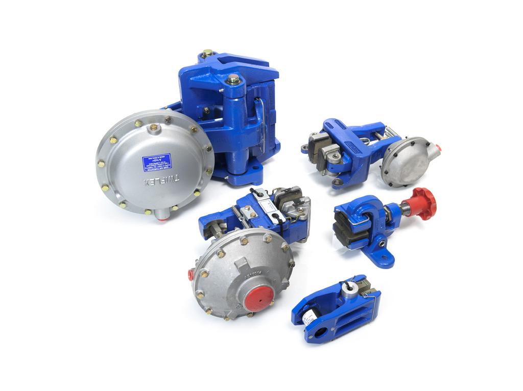
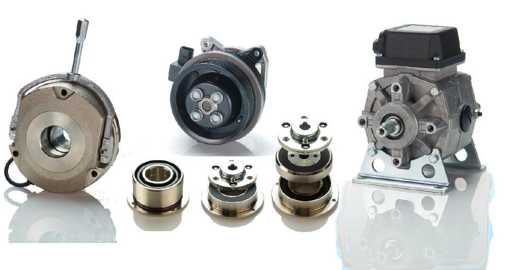
1 Solutions for power transmission KEB-sähkömagneettiset jarrut ja kytkimet
2 MAGNET TECHNOLOGY EN

3 KEB AUTOMATION KG All our efforts are directed towards the development, production and application of electromagnetic technology throughout our extensive range of brakes and clutches. The functions, starting, stopping, positioning and safe holding of moving axes in machines and plant call for reliably designed and safely functioning components. With our advanced manufacturing techniques we are able to produce high quality, high-grade products, and through our continued investment we now have manufacturing plants worldwide. We have the ability to produce high volume stock parts or ones that are tailored specifically to your requirements. 2


4 SAFE BRAKING AND HOLDING COMBISTOP H COMBISTOP D COMBISTOP T COMBISTOP starting fom page 4 Electromagnetically actuated dual-surface spring applied DC brakes for dry operation. COMBISTOP N COMBIPERM P1 COMBIPERM PC COMBIPERM P1 COMBIPERM starting fom page 16 Permanent magnet brakes and clutches for dry operation. SWITCHING, STOPPING, POSITIONING COMBINORM C COMBINORM B COMBINORM K COMBINORM starting fom page 22 electromagnetic-actuated open-circuit operated clutches and brakes without slip rings. COMBIBOX COMBIBOX starting fom page 36 a ready to be installed electromagnetic- actuated clutch-brakemodule POWER SUPPLY / SWITCHGEAR COMBITRON 91 COMBITRON 98 COMBITRON 94 COMBITRON starting fom page 44 DC-supply from the alternating voltage supply system and electronic switches for electromagnetic clutches and brakes. 3
5 COMBISTOP PROGRAM SCHEDULE COMBISTOP are electromagnetically actuated dual surface spring-applied DC brakes for dry application. The braking force is applied by the springs and released through the electromagnetic force. These brakes are successfully working in the most demanding applications and are used wherever rotating masses must be stopped or shafts need to held in a precise position. High quality materials together with high precision manufacturing, process inspections and functional testing guarantee reliable, safe operation. On request we can design the COMBISTOP brake to your requirements, for example the brake can be supplied with pre-mounted armature and increased torque. Please bear in mind that the rated torques are achieved after a required running-in process. certified to PROGRAM SCHEDULE COMBISTOP ELECTROMAGNETICALLY ACTUATED DUAL-SURFACE SPRING APPLIED DC BRAKES Mini brake Nm Page 5 COMBISTOP M Holding brake for dynamic demands ,000 Nm Page 6 COMBISTOP N Holding brake for static application ,500 Nm Page 6 COMBISTOP H Holding brake for protection class IP Nm Page 8 COMBISTOP T Double-brake for theatre, lift and elevators 2 x x 1,000 Nm Page 10 COMBISTOP D Hoisting brakes, elevator brakes D8 2 x x 125 Nm Page 10 COMBISTOP L Accessories Page 12 TECHNICAL DATA Switching times Page 15 Dimensions / Calculation Page 50 Legend Page 51 ACCESSORIES COMBISTOP M N H T D L Friction disk x x x X Flange x x x x x X Friction disk with collar X X Dust protection ring x x x Micro switch x x x X Hand release x x x x x TERMINAL BOX X X X X X 4

 α weight [Nm] [W] [kg] 0B08 0.3 6 34 5 8.3 23 5.5 9.8 14.7 3.5 30 40 0.1 4.7 0.15 0008 0.5-2 11-15 59.5 52 10 2) 14 29.5 0.5-1 4.")
6 COMBISTOP M stands for MINI Brake, the small compact solution with torques up to 2 Nm. The brake is characterized by a particular compact construction, it is designed for small loads and holding functions without torque adjustment and adjustability and available with or without hand release. Range of application: e.g. general machine building, small-power motors, automation technique, apparatus engineering. SIZE T 2N P 20 A B D F G H K N O P T U V W X a 1 b 1 c e g m 3) α weight [Nm] [W] [kg] 0B ) All dimensions in mm keyway according to DIN 6885/1 according to VDE 0580, isolation class B rated torque after running in process 2) bore tolerance max Ø 10 mm H7, otherwise H8 3) Mounting dimension m with attracted armature COMBISTOP M 0B08110 without hand release O COMBISTOP M without hand release with hand release Accessories COMBISTOP M flange 5

7 COMBISTOP N AND H COMBISTOP N and H are the standard series of dual-surface spring-applied brakes in two designs: - dynamic applications with continuous stress COMBISTOP N - static applications with short-term stress COMBISTOP H COMBISTOP N: Rated torque in the range Nm - designed for dynamic applications with regular brake applications at high speed! Range of application: e.g. brake motors, geared brake motors, wind energy plants, refrigerated warehouses Option: Cold Climate Version CCV ( C) ISO-class F + H Accessories COMBISTOP N Friction disc Flange Friction disc with collar (up to size 06) Duats protection ring Micro switch COMBISTOP N - dynamic operation COMBISTOP H - static operation X.. without hand release X.. with hand release Size ORDERING EXAMPLE: COMBISTOP N / H X / X3X Type V DC, Ø D? Design 6

8 Version N Version H SIZE T 2N P 20 T 2N P 20 H7 weight A B Ø D E G H K L N O P T U X a b e g Nm W Nm W max. kg , ** 22 34,2 1-1, , ,5 3x4, ,2 105,5 53,5 23 7, ,2 2-2, , x5, , ,5 8 1, ,2 2-2, , ,5 3x6, , ,2 10, ,7 2, , ,5 3x6, , ,5 12 4, ** 47 59,8 2, , x , , , ,5 3x , ,5 57/76* *87, x , , , , x , ,8 9, , x , , , ,5 6x ,6 *** *** *** All dimensions in mm keyway according to DIN 6885/1 Standard voltage 24 / 105 / 180 / 205 V DC according to VDE 0580, isolation class B, 100% on time, Type of protection IP40, with dust protection ring IP44 rated torque after running in process * hub bore > ø 45 ** keyway according to DIN 6885/3 *** mech. release with hexagon screw COMBISTOP H: Rated torque in the range Nm - designed for static applications, i.e. braking from low speeds and secure holding of loads! Range of application e.g. electronically controlled or regulated drives, wind energy plants, refrigerated warehouses Accessories COMBISTOP H Friction disk Flange Friction disc (up to size 06) Dust protection ring Micro switch 7
9 COMBISTOP T A brake design which are always used whenever the application puts higher demands on the protection class. COMBISTOP T: the IP 65-brake with identical hole circle such as COMBISTOP N and H, optionally completely closed on the backside or prepared for the attachment of tacho-generators or shaft sealing ring. Range of application: e.g. general machine building, crane construction, ship gear, wind energy plants, refrigerated warehouses COMBISTOP T..28G10 standard version without hand release..28g20 standard version with hand release..28g1t for tacho-generators without hand release..28g2t for tacho-generators with hand release..28g1w for shaft sealing ring without hand release..28g2w for shaft sealing ring with hand release SIZE T 2N P 20 øa 1 øa øb C ød øe øe 1 øf øg H øk L M M 1 N O [Nm] [W] h8 max. H ** x x x x ** x x * x x SIZE øp øp 1 øp 2 R T øv X a 1 b 1 ød e sw øf øg s k L 1 l M x M M x M M x M M x M M x M M x M M x M M x M see dimensions diagram 28.M All dimensions in mm keyway according to DIN 6885/1 standard voltage 24/105/180/205 V DC according to VDE 0580, ISO-class B, 100% on time, rated torque after running in process * hub bore > ø 45 ** keyway according to DIN 6885/3, Attention: under the fixing screws are sealing washer (DIN7603) have to be used 8
 ISO class F + H Accessories COMBISTOP T Flange Hand release Shaft sealing ring Size")
10 Option Cold Climate Version CCV ( C) ISO class F + H Accessories COMBISTOP T Flange Hand release Shaft sealing ring Size ORDERING EXAMPLE: COMBISTOP T GXX Design Type V DC, Ø D? 9
11 COMBISTOP D AND L COMBISTOP D stands for double safety and covers a series of double brakes, which is prepared for tasks with redundant brake circuits. The mechanical construction with two completely independent fail-safe spring-applied brakes meets the requirements according to DIN (BGV C. The brakes are supplied ex factory, ready for attachment with preadjusted air gaps. Extensive constructional measures reduce the switching and running noises to a minimum. Range of application: e. g. theatre equipment, passenger and freight elevators Option: ISO class F 1 & 2 SIZE T 2N P 20 A B C D E F H L 1 L 2 M N 1 N 2 R 1 T X a b e 1 (Nm stat) (W) (max) 02 2x5 2x ** x10 2x x20 2x x36 2x x70 2x ** x100 2x x150 2x /76* x250 2x x500 2x x1000 2x180 on request All dimensions in mm keyway according to DIN 6885/1 standard voltage 24 / 105 / 180 / 205 V DC according to VDE 0580, ISO-class B, 100% on time, rated torque after running in process * hub bore > ø 45 ** keyway according to DIN 6885/3 COMBISTOP L as special development for the elevator industry the dual-circuit spring-applied faill-safe brake fulfills the valid requirements of EN 81 respectively TRA 227. The brake series, tested by the technical inspection authority, contains two mechanical braking circuits and offers compact dimensions and easy mounting Range of application: e. g. theatre equipment, passenger and freight elevators Option: ISO class F * H Accessories COMBISTOP L Friction disc Flange Micro switch SIZE 2 x T 2N P 20 H L (Nm stat.) (W) A B C D H7 E F G D8230 D8630 D8230 D8630 N O X n SIZE a b d e l m P 1 * P 2 * P 3 * 2 x X V SW α δ D8230 D8630 ISO 4762 ISO 4762 ISO 4762 D M6x65 M6x10 M5x M8x80 M8x12 M6x M10x100 M10x16 M8x All dimensions in mm keyway according to DIN 6885/1 standard voltage 24 / 105 / 180 / 205 V DC according to VDE 0580 ISO-class B 100% on time, rated torque after running in process * hub bore > ø 45 ** keyway according to DIN 6885/3 see dimension diagram D8.M

12 Accessories COMBISTOP D Friction disc Micro switch Dust protection ring Flange Friction disc with collar (up to size 06) Size ORDERING EXAMPLE: COMBISTOP D DDN Design Type V DC, Ø D? FASTENING SCREWS e 2 d 1 d 2 m Z Z 1 Z 2 Z 3 1/2/ M4 3x8.8 3x8.8 3x M5 3x8.8 3x8.8 3x M6 3x8.8 3x8.8 3x M6 3x10.9 3x8.8 3x M8 3x10.9 3x8.8 3x M8 6x8.8 3x8.8 3x M8 6x10.9 3x10.9 3x M10 6x8.8 3x10.9 3x M10 6x10.9 6x8.8 3x8.8 a b COMBISTOP D... 38DDN... Hub variation 1 ca. T x60 15 Ø A Ø B Ø F H7 1 Ø E Ø D Z 1 R 1 L 2 L 1 H e 2 e 1 m M d 2 d 1 Z 2 Z 3 N 1 m M Ø D H7 2 Ø C H8 25 X X see dimension diagram Ø E M N 2 M Hub variation 2 COMBISTOP L.. D COMBISTOP L.. D with hand release with hand release, with backlash-free-hub lining system α Size ORDERING EXAMPLE: COMBISTOP L 05 D8 230/630 Type V DC, Ø D? Design a P 3 * b 15 SW Ø d 100 4x x brake attachment 80 Ø A Ø B Ø C Ø E Ø D H7 l H L e N P 1 * Ø F Ø G ca. 500 δ 05.D x attachment for friction disc P 2 * x v x n backlash-free hub-lining-system m +0,2 O 11
13 COMBISTOP ACCESSORIES To adapt the spring-applied brakes to the various requirements of different applications an extensive program with a wide range of accessories is available. Please contact us to discuss your requirements. To ensure correct selection we have on hand an experienced team of application engineers to assist you in all aspects of selection, enabling you to get the optimum solution. ACCESSORIES - DUST PROTECTION RING (IP44) ARTICLE NUMBER XX SIZE B 1 22, ,5 38,5 45, ,5 63 W auf Anfrage! All dimensions in mm Ø W 5 To protect the friction surfaces against dust or dripping water different sizes of dust protection rings are available. When fitting the COMBISTOP with a dust protection ring the friction disc xx08515-xxxx must be used on the motor side. This friction disc will be supplied nitrated and is especially designed to hold the dust protection ring. B 1 ACCESSORIES - MICRO SWITCH The use of COMBISTOP can be fitted with a micro switch for monitoring the functions and the wear. The use of COMBISTOP with micro switch is particularly sensible for braking motors on hoisting gears that are operated with frequency inverters. 12
14 Friction discs and flanges provide suitable counter-rotation surfaces for the spring applied brakes and are available in hardened and rustproof design. ACCESSORIES - FRICTION DISC ARTICLE NUMBER XX08451-XXXX T 1 SIZE B P 4,5 5,5 6,5 6, T1 1, ,5 2,5 2,5 3 4 P3 7,5 8,5 10,5 10,5 14,5 14,5 14, V ,5 42, W Weight [kg] 0,05 0,10 0,15 0,22 0,30 0,40 0,64 0,93 1,50 Ø B Ø V 2 Ø P Ø W 2 P x 60 All dimensions in mm ACCESSORIES - FRICTION DISC WITH COLLAR ARTICLE NUMBER XX08515-XXXX SIZE B P 4,5 5,5 6,5 6,5 9 T 1 1, ,5 V ,5 42, W 1 88, Weight [kg] 0,05 0,10 0,15 0,25 0,35 Ø B Ø V 1 Ø P Ø P Ø W 1 T All dimensions in mm ACCESSORIES - FLANGE WITH COLLAR FOR DUST PROTECTION RING ARTICLE NUMBER XX T 4 P 4 SIZE B P4 3x4,3 3x5,3 3x6,4 3x6,4 3x9 3x9 3x9 3x11 6x11 6x13 S1 3xM4 3xM5 3xM6 3xM6 3xM8 3xM8 3xM8 3xM10 6xM10 6xM12 T ,5 20 V W Weight [kg] 0,08 0,20 0,35 0,75 1 1,50 2,10 2,70 3,70 5,90 12,7 Ø B Ø V 4 Ø S 1 Ø W All dimensions in mm 13
15 COMBISTOP TECHNICAL DATA max. speed J G min X N Operating- Type M. T Type N. H. D Type M. T Type N. H. D SIZE stop emergency stop emergency stop [rpm] [rpm] [rpm] [10-3 kgm 2 ] [10-3 kgm 2 ] [mm] [mm] 00 3,000 6, ,000 6,000 6, ,000 6,000 6, ,000 6,000 6, ,000 5,000 5, ,000 5,000 5, , , ,500 3,000 3, ,500 3,000 3, ,500 2, gmin min. permissible lining thickness [mm] for brake type D use for calculation 2 x [J] PERMISSIBLE FRICTION W Rmax [J] DEPENDENTION THE SWITCHING FREQUENCY Valid only for the stated revolutions per minute type M, T, N, H, D type T, N, H, D size rpm size rpm The values for W Rmax are valid for standard brakes and a second friction surface of casting. Depending on application these values may be exceeded or remained under. Rustfree friction discs, or speeds higher than specified in the diagram, reduce the permissible friction work considerably. If the rated torque of the brake is reduced by turning the adjustment ring (optional) the permissible friction work increases. Friction switching frequency Type M, T Friction switching frequency Type N, H, D WR max [J] W Rmax [J] switching frequency per hour Red line for brake without friction disc switching frequency per hour 14
16 SWITCHING CYCLES AND SWITCHING TIMES SWITCHING CYCLES AC-SWITCHING DC-SWITCHING SIZE SC 1 SC 2 t 2 t 11 ~ t 1 ~ t 11 = t 1 = [rpm] [rpm] [ms] [ms] [ms] [ms] [ms] M, T N, H, D M, T N, H, D M, T N, H, D M, T N, H, D M, T N, H, D M, T N, H, D M, T N, H, D ,200 1, ,400 1,400 1,800 2, ,100 3, SC 1 applicable for rectifiers: CE CE CEMV SC 2 applicable for rectifiers: CE CE CE CE09 COMBISTOP Typs: M, T, N, H, D (see page 4) SC t 1 t 11 t 2 maximum permissible switching cycle at DC-side switching, 100% on time and max. operating temperature of 80 C. engaging time time from disconnecting the current to attaining the rated torque. engaging delay time time from disconnecting the current to the rise of the torque. release time time from connecting the current to the beginning of torque decrease. [rpm [ms] [ms] [ms] The designation of the switching times corresponds to DIN VDE 580 SWITCHING CYCLES COMBISSTOP WITH POWERBOX SIZE t 2 max. air gap switching cycles [ms] [mm] [rpm] * POWERSUPPLY COMBISTOP requires DC voltage for operation. For the power supply different half-wave or full-wave rectifiers of the series COMBITRON 98 are available for DC or AC-side switching, which, depending on the type, are suitable for connection voltages up to 720 V AC rated voltage. The switching characteristics and functions of the COMBISTOP can be optimized through the rapid switch rectifier COMBITRON 98.. * Continuos operation only permissible 45 C! 230 V AC input voltage and 105 V DC coil Switching times apply to rated air gap X Switching cycles apply to DC side switching 15
17 COMBIPERM PROGRAM SCHEDULE COMBIPERM are electromagnetically released permanent magnet brakes and clutches for dry operation whose flux is generated by permanent magnets. This effect permits the connection of shafts in voltage free condition or the safe deceleration of masses. You find possible shaft diameters in the Bore Table on page 51. On request we adapt COMBIPERM to your constructional and electrical requirements. PROGRAM SCHEDULE COMBIPERM quiescent-current operated brakes and clutches Holding brake with Emergency-Stop-function Nm page 17 COMBIPERM P1 Clutch quiescent-current operated Nm page 19 COMBIPERM PC TECHNICAL DATA Switching times page 20 Moments of inertia, friction, -rating page 21 Dimensioning / Calculation page 50 Bore table COMBINORM / COMBIPERM page 51 COMBIPERM P1 COMBIPERM PC 16
 in current-supplied condition and in combination with the membrane spring on the armature it")
18 COMBIPERM P1 FIRST CHOICE FOR YOUR SERVOMOTOR are powerful permanent magnet brakes with frictionally engaged, backlash-free effect. Rare earth magnets create a force field, which is cancelled by the counter-pole magnet coil (opened) in current-supplied condition and in combination with the membrane spring on the armature it ensures a residual torque-free separation independent of the installation position. COMBIPERM P1 are designed for rated operating voltage 24 V DC according to ISO class F (max. 155 C) and ensure a safe operation within a wide range of temperatures. On request versions in other operating voltages are available. certified to Range of application: e.g. machine building, medical technology, industrial robots, servo-drives Please bear in mind that magnetic materials within the direct surroundings can weaken the torque, reduce maximal air gaps and lead to a shifting of the release range. that the rated torques are achieved after a required running-in process (please see instruction manual). that the torques become less at higher speeds Size ORDERING EXAMPLE: COMBIPERM P1 06 P1 130 Design Type V DC, Ø D? COMBIPERM - brake with current - 50 [V] C C COMBIPERM - brake without current - 10 X min X max 17
19 COMBIPERM P1 SIZE T 2N P 20 A h8 A 1 A 2 h8 A 3 B B 1 C H8 C 1 C 2 D E Ø F G H J K [Nm] [W] x x x x x x x x x SIZE K 1 L L 1 L 2 M N P R R 1 R 2 S H7 d 20 H7 d 30 H7 d 30 X min 20 X max Z weight kg xM xM xM xM xM xM xM xM xM xM xM xM xM xM xM xM xM xM upon request 18


20 COMBIPERM PC are permanent magnet clutches, which transmit in currentless condition frictionally engaged torque. The magnetic circle is optimized by the arrangement of the permanent magnets in the armature, thus permitting the transmission of high torques on small constructional spaces. The opening of the friction-type connection takes place by the antipole connection of the electromagnetic circuit, thereby neutralizing the force action of the permanent magnets Range of application: e.g. robot technique, medical equipment SIZE T 2N P 20 Data [Nm] [W] upon request rated torque after running in process 07PC230-xxxx 07PC110-xxxx 19
21 COMBIPERM TECHNICAL DATA Permissible friction W Rmax [J] depending on the switching frequency type P W Rmax [J] 5 x x x x x switching frequency per hour [h -1 ] The values for W Rmax apply to a speed 3000 rpm. Dependent on the actual application W Rmax may exceed or fall below these values.. POWER SUPPLY COMBIPERM P1 needs a smoothed DC voltage. To ensure a safe operation in case of large temperature variations, the coil should be supplied with constant current. Please pay attention to the polarity of the connection leads. (positive = red, negative = black). 20
22 COMBIPERM P1 SIZE T 2N 20 C [Nm] Tstat. 100 C Tdyn. 20 C [Nm] [kgm 2 ] [rpm] 3,000 3,000 3,000 3,000 2,000 2,000 2,000 2,000 2,000 P 20 [W] J Armature P1.110 [10-4 kgm 2 ] P1.120/ W R 0,1 [kj] ,290 2,900 6,200 13,000 [kgm 2 ] [rpm] 3,000 3,000 3,000 3,000 2,000 2,000 2,000 2,000 2,000 Xmax 20 C [mm] Xmin nmax [rpm] 10,000 10,000 10,000 10,000 10,000 10,000 10,000 8,000 8,000 Switching times t 2 [ms] t 11 = t 1 = LEGEND T 2N rated torque after running in process [Nm] (slip speed 20 rpm) T stat. 100 C rated torque at 100 C [Nm] (slip speed 20 rpm) T dyn.. 20 C switching torque at specified conditions [Nm] P 20 power at 20 C [W] J moment of inertia [kgm²] n max max. speed [rpm] X min nominal air gap [mm] X max max. air gap at which the armature attracts [mm] W R 0,1 friction work up to 0.1 mm abrasion [kj] t 1 t 11 t 2 Engaging time: Time from disconnecting the current until the rated torque is attained Engaging delay time: Time from disconnecting the current until the torque rises Release time: Time from connecting the current until the torque decreases [ms] [ms] [ms] The stated switching times are achieved with adjusted nominal air-gap (x min ). These are averages whose dispersion depends on the power supply and coil temperature. 21
23 COMBINORM PROGRAM SCHEDULE COMBINORM - operating-current operated brakes and clutches use the flux of an electromagnet, concentrated on two pole surfaces, for the connecting, separating or holding of shafts and the connected loads. COMBINORM covers a complete program with brakes, clutches and combinations as installation and attachment components for the applications in machines, plants and equipment in the application range of 0.5 to 500 Nm. On request we adapt the KEB COMBINORM to your constructional and electrical requirements. Please bear in mind that the rated torques are achieved after a required running-in process. PROGRAM SCHEDULE COMBINORM OPERATING-CURRENT OPERATED BRAKES AND CLUTCHES Operating current brake Nm page 24 COMBINORM B Operating current clutch-brake-combination Nm page 26 COMBINORM K Operating current clutch Nm page 27 COMBINORM C Operating current toothed clutch Nm page 32 COMBINORM T FLANGE MOUNTED BRAKE COMBINORM B ➀ brake magnet ➁ armature ➄ hub ➅ spring FLANGE MOUNTED CLUTCH COMBINORM C and T ➁ ➂ ➃ ➅ armature clutch magnet rotor spring 22
24 TECHNICAL DATA Switching times page 34 Moments of inertia, friction, rating page 35 Dimensioning / Calculations page 50 Bore table COMBINORM / COMBIPERM page 51 Size ORDERING EXAMPLE: COMBINORM C Design Type V DC, Ø d 1, Ø d? SHAFT MOUNTED CLUTCHES COMBINORM C and T ➁ armature ➂ clutch magnet ➃ rotor ➅ spring CLUTCH-BRAKE-COMBINATION COMBINORM K ➀ ➁ ➂ ➃ ➄ ➅ brake magnet armature clutch magnet rotor hub spring 23
25 COMBINORM B SIZE 2N P 20 A h8 B C H8 C 1 C 2 d/d 4 d 5 D E F G H J K K 1 M [Nm] [W] max x x x x x x x x x x x Dimensions and technical data see drawing available shaft diameters page 51 All dimensions in mm Ø d keyway according to DIN 6885/1-P9 (design /120/130) Ø d4 keyway according to DIN 6885/1-H8 (design ) COMBINORM B are the most economical solution for the deceleration and holding of loads for the flange- and shaft-mounted installation in machines and plants. The magnets with a rated voltage of 24 V DC are designed according to ISO class B and are available in various special voltages on request. Shaft mounted brakes COMBINORM B d4 d5 24
![N N 4 O O 1 O 3 P P 6 R R 1 R 5 S S 4 U V 1 W 4 X Z Z 1 weight [kg] 110 120/130 320 13.7 5 1.5 1 2.3 4.3 7 2.5 0.1 1 x M 3 0.05 0.05 17 7.5 2 1.3 2.1 4.1 10 4 0.15 1 x M 3 0.1 0.1 20 7 2 1.5 2.7 5.3 12 5 0.](/docs-images/93/111508784/images/26-0.jpg "15 1 x M 4 0.15 0.15 22 7.5 2 1.5 3 6 12 5 0.2 1 x M 5 0.2 0.25 18 31.2 6 3 19 2 9.3 3.8 7.3 6.3 15 45 39 6 M4 0.2 M6 1 x M 6 0.3 0.3 0.8 20 34.2 7 3 21.5 2 13.2 4.3 8.3 6.9 20 52.5 45 8 M5 0.")

26 N N 4 O O 1 O 3 P P 6 R R 1 R 5 S S 4 U V 1 W 4 X Z Z 1 weight [kg] / x M x M x M x M M4 0.2 M6 1 x M M5 0.2 M8 1 x M M6 0.2 M8 1 x M M8 0.3 M8 2 x M M M10 2 x M x M x M Standard voltage 24 V DC VDE 0580, ISO-class B rated torque after running in process Range of application: e.g. mail processing, winding equipment, door and gate systems, roller conveyor, strapping machines, balancing machines, sorting machines. Flange mounted brake COMBINORM B X
![COMBINORM K SIZE T 2N P 20 A h8 B C H8 C 2 d d 1 F K K 1 K 2 L 5 N N 1 O O 1 R 2 S S 6 X Weight [Nm] [W] max. max. [kg] K B 06 7 15 12 80 72 35 36 20 20 4.5 3.5 1.6 11.2 55.1 18 24 6 3 12.9 15 20 0.](/docs-images/93/111508784/images/27-0.jpg "2 0.85 07 15 20 16 100 90 42 43.5 22 25 5.5 4.25 1.85 9.3 61.3 20 26.5 7 3 14.6 20 22 0.2 1.5 08 30 28 21 125 112 52 53.8 30 30 6.6 5 2.15 8.9 71 22 30 8 4 18.8 25 24.5 0.2 2.7 09 65 35 28 150 137 62 63.")
27 COMBINORM K SIZE T 2N P 20 A h8 B C H8 C 2 d d 1 F K K 1 K 2 L 5 N N 1 O O 1 R 2 S S 6 X Weight [Nm] [W] max. max. [kg] K B available shaft diameters page 51 All dimensions in mm keyway according to DIN 6885/1-P9 Standard voltage 24 V DC VDE 0580, ISO-class B rated torque after running in process COMBINORM K covers a series of houseless construction units, designed for the connection and holding of auxiliary drives, allowing a backlash-free transmission with spring-controlled armature systems. The installation is done directly in the machine construction. Range of application: e.g. paper processing, laundry folding equipment, feeder Clutch-brake-combination COMBINORM K
28 COMBINORM C SIZE T 2N P 20 A h8 B C H8 C 1 C 2 d d 1 D E F G H [Nm] [W] max max x x x x x x x x x x x SIZE J K K 1 M N 1 O O 1 P R R 1 S S 1 T V 1 X Z 1 Weight [kg] x M x M x M x M x M x M x M x M x M x M x M available shaft diameters page 51 All dimensions in mm keyway according to DIN 6885/1-P9 Standard voltage 24 V DC VDE 0580, ISO-class B rated torque after running in process COMBINORM C the switchable shaft connections are proven millions of times in the machine building and allow the controlled connection and disconnection of functional parts in an especially easy manner. Electromagnets according to ISO class B with rated voltage of 24 V DC create a flux, whose effect leads over the pole surfaces of the rotors and armatures. Available on request in various special voltages. Range of application: e.g. paper processing, winding drives, door and gate systems, feed strapping machines, sorting machines Flange mounted clutches COMBINORM C X
29 COMBINORM C TABLE ( SIZE T 2N P 20 B 1 C C 1 C 4 d d 2 d 6 D E F 1 G H J L 4 M M 1 N 2 [Nm] [W] max max max x x x x x x SIZE O 5 P P 2 P 4 Q R R 1 S S 2 S 5 T U V 1 X Z Z 1 Weight [kg] M3 M M3 M M4 M M4 M M4 M M6 M available shaft diameters page 51 All dimensions in mm keyway according to DIN 6885/1-P9 Standard voltage 24 V DC VDE 0580, ISO-class B rated torque after running in process TABLE ( Shaft mounted clutches size COMBINORM C X
30 TABLE(2) DIZE T 2N P 20 A h8 A 1 B B 1 C C 1 d d 3 D D 2 E E 1 F F 1 G H J [Nm] [W] max max x x x x x x x SIZE M O 2 P P 3 P 4 P 5 R R 1 S S 3 T V V 1 W W 1 X Z 1 Weight [kg] 210/710230/ xM xM M5 10 M xM M8 12 M xM M8 15 M xM M10 19 M xM M10 22 M xM available shaft diameters page 51 All dimensions in mm keyway according to DIN 6885/1-P9 Standard voltage 24 V DC VDE 0580, ISO-class B rated torque after running in process TABLE (2) Shaft mounted clutches size COMBINORM C... 03XX0... design torque support size size design flange
31 COMBINORM C SIZE T 2N P 20 T A 2) A h8 A 1 B B 1 C 5 D D 2 D 3 D 4 d 4 d 7 d E E 1 E 2 F F 1 G H J [Nm] [W] [Nm] max max x4.5-3x x5.5-3x x x x x x available shaft diameters page 51 All dimensions in mm keyway according to DIN 6885/1-P9 Standard voltage 24 V DC VDE 0580, ISO-class B rated torque after running in process 2) tightening For flexible clutches (type ) the following additional instructions are applicable: The radial and axial screws connecting the rubber element to the hubs must all be tightened to the torque (T A2 )) given in the table, using a torque wrench. Ensure that when tightening the screws the aluminium bushes do not twist in the rubber part and that they sit squarely. In order to reduce friction between the screw head and the aluminium bush smear a small amount of grease under the head of the screw before fitting. If necessary use a suitable tool to apply counter pressure on the element to prevent twisting of the rubber part while tightening the screws. This is particularly important with the radial screws otherwise the curved faces between the aluminium bush and the hub will not engage on the full area but only across the two sides. This will inevitably lead to slackening of the screws and destruction of the clutch. If the clutch is supplied in a pre-assembled state, do not dismantle it, but fit it in this condition. Shaft mounted clutches with bearing take-up for the output COMBINORM C design torque support size size design flange
![J 3 K 3 L L 1 L 2 L 3 M 2 M 3 M 4 O 1 O 2 P P 3 P 4 P 5 S 3 T T 1 V W W 1 W 2 X Z Weight [kg] 810 840 2 1.3 32.9 25.6 80 117 30 24 19 3 19 2 - - 4 41 67 56 - - - 2 x M 6 0.2 M 5 1 1.7 4 1.6 37.7 29.](/docs-images/93/111508784/images/32-0.jpg "9 90 129 30 24 20 3 21.5 2 - - 4.5 45 85 85 - - - 2 x M 8 0.2 M 6 1.8 3 4 1.85 35.2 32.15 96 141 35 28 23-24 2.5 16.2 12 5.5 51.5 106 100 M 5 M 4 46.5 3 x M 8 0.2 M 8 2.7 4.1 4 2.15 37.6 34.")

32 J 3 K 3 L L 1 L 2 L 3 M 2 M 3 M 4 O 1 O 2 P P 3 P 4 P 5 S 3 T T 1 V W W 1 W 2 X Z Weight [kg] x M M x M M M 5 M x M M M 8 M x M M M 8 M x M M M10 M x M M M10 M x M M SIZE Compliance [mm] of flexible clutches radial axial Shaft mounted clutches with flexible clutch COMBINORM C design torque support size size design flange

![roller, aggregate connection SIZE T 2N P 20 C A h8 A 1 B B 1 C H8 C 1 C 2 D d 1 D 2 d 3 d E E 1 [Nm] [W] max max max 06 21 15 80-72 - 35 32 36 63 20-17 18 50-07 45 20 100-90 - 42 38 43.](/docs-images/93/111508784/images/33-1.jpg "5 80 25-22 22 60-08 90 28 125 62.5 112 56 52 48 53.8 100 30 85 30 30 76 45.75 09 195 35 150 75 137 68.5 62 58 63.8 125 35 95 35 35 95 55 10 390 50 190 95 175 87.5 80 73 82.1 160 50 126 50 45 120 72.")
33 COMBINORM T COMBINORM T are electromagnetically operated tooth clutches for wet or dry operation. Torque is transmitted by the leading faces of hardened serrations and is backlash free. Large torques are transmitted with less space requirements in both directions. On request available in various special voltages. Range of application e.g. door drives, printing machines, transport roller, aggregate connection SIZE T 2N P 20 C A h8 A 1 B B 1 C H8 C 1 C 2 D d 1 D 2 d 3 d E E 1 [Nm] [W] max max max available shaft diameters page 51 Flange mounted tooth clutch COMBINORM T X
34 SIZE F F 1 G H 1 J K K 1 M 5 N 1 O O 1 O 2 P P 3 P 4 P x4.5-3x x5.5-3x x x x x x9 9 3x SIZE R 3 R 4 S S 1 S 3 T 1 V V 1 W W 1 X Z 1 weight [kg] 210/ / x M x M M5 10 M x M M8 12 M x M M8 15 M x M All dimensions in mm keyway according to DIN 6885/1-P9 Standard voltage 24 V DC VDE 0580, ISO-class B Shaft mounted tooth clutches COMBINORM T... 07XX design torque support size size design flange
35 COMBINORM TECHNICAL DATA DC-SIDE SWITCHING CURRENT / TIME AND TORQUE / TIME DIAGRAMS The mentioned designations of switching times are according to DIN VDE 580. The specified switching times are achieved with adjusted nominal air gap (xmin). It concerns average values whose scattering depends on the current supply and the coil temperature. The torques specified in the measuring tables are safely achieved with single-side clutches and brakes after a run-in phase at 100 rpm. In new condition and in case of substantially higher speeds the torques are possibly smaller. CURRENT SUPPLY The COMBINORM requires a DC voltage, which can be made available by different rectifiers, transformer rectifiers as well as electronic switches of the series COMBITRON 91 and 94. A short-time overvoltage produces very short switching times and high switching accuracies. I t M t11 Average switching times [ms] with nominal air gap M 2N 0,9M 2N 0,1M 2N t t1 t2 34
36 COMBINORM 02 / 03 / 04 / 07 SIZE T 2N 02/03/04 20 C [Nm] P 20 02/04 brake 20 C [W] /04/07 clutch 20 C J Armature 110/210/610/710/810 [10-4 kgm 2 ] /130/230/630/ Rotor 110/130/140/170/ / /230/240/710/730/ W R max. 02/03/04 [10 4 J] W R 0,1mm 02/03/04 [10 7 J] P R max. 02/04 brake [J/s] /04 clutch Xn max /03/04 [mm] X 02/03/ /03/04/07 [min -1 ] 10,000 10,000 10,000 10,000 8,000 6,000 5,000 4,000 3,000 3,000 2,000 n max. EXCEPTION CLUTCH! 1,500 1,500 1,500 1,500 1,500 1, /630/640 Switching times Brake 02/04 t 2 DC [ms] t 2 AC nominal voltage t 11 = t 1 = x nominal voltage t 11 = t 1 = Clutch t 2 DC [ms] /04 t 2 AC nominal voltage t 11 = t 1 = x nominal voltage t 11 = t 1 = LEGEND T 2N rated torque after running in process [Nm] T erf required torque [Nm] J moment of inertia [10-4 kgm 2 ] P 20 power at 20 C [W] n max maximum speed [min -1 ] X rated air gap [mm] X n clearance at which an adjustment is recommended [mm] W Rmax permissible friction per switching operation [10 4 J] W R0,1 friction work up to 0,1 mm wear [10 7 J] P Rmax permissible friction work per second [J/s] I magnet-rated current [A] t time [ms] t 1 Engaging time: Time from connecting the current the rated torque is attained [ms] t 11 Engaging delay time: Time from connecting the current until the torque rises [ms] t 2 Release time: Time from disconnecting the current until 0.1 T 2N [ms] 35


37 COMBIBOX PROGRAM SCHEDULE COMBIBOX CLUTCH-BRAKE-COMBINATION TYPE 10 / 09 / 06 with an energised to engage single sided clutch / brake COMBIBOX 10 page 37 with an energised to engage single sided clutch without brake COMBIBOX 09 page 37 with an energised to engage single sides clutch / and energised COMBIBOX 06 page 37 to disengage single sided permanent magnet brake TECHNICAL DATA COMBIBOX shaft in / shaft out page 38 COMBIBOX bore in / bore out page 39 COMBIBOX bore in / shaft out page 40 COMBIBOX shaft in / bore out page 41 Moments of inertia, friction work and calculations page 42 On request we adapt the COMBIBOX to your constructional and electrical requirements. DESIGN ATTACHMENTS Input Output 360 / / / / / / / / / / / /


38 The COMBIBOX is a ready to install electromagnetic actuated clutch-brake module in a single housing. The modular system is designed for a multitude of variants; these covering most of the applications in the field. The patented adjustment procedure permits an air gap readjustment in it s installed condition. Thus giving a greater lifetime of the wear affected components. The units designed for Start-Stop-operation considerably reduce the energy consumption due to a continuously running drive. TYPE 10 has an energise to engage single sided brake, this is the most commonly used, permitting high switching frequency and good positioning accuracy. The COMBITRON rapid switch can be used with this variant to achieve expectionally high switching frequencies. The rated torque of both clutch and brake are identical. TYPE 09 is the COMBIBOX version without brake, i.e. an electrical clutch in a housing for the use between e.g. motor and gear unit. TYPE 06 has an energise to disengage permanent magnet single-side brake. The characteristic of this variant is that the position of the output shaft is kept safe and backlash-free in currentless condition. The rated torque of the brake is slightly lower than that of the clutch. 37
39 COMBIBOX SHAFT IN / SHAFT OUT SIZE a 3 a 4 a 7 b c e f 2 f 5 g h h 1 i k k 1 n s s 2 u Shaft Weight d 1 I [kg] / / / / M / / / / / M / / / / / M / / / / / M / / / / / M / upon request Alle dimensions in mm keyways according to DIN 6885/1 centerings D according DIN 332/2 standard voltage 24 V DC VDE 0580, ISO-class B Rated torques type 10 / 09 / 06 SIZE T 2N [Nm] clutch / - brake 7 / 6 15 / / / / / - P 20 [W] clutch / - brake 12 / / / / / / - rated torque after running in process variations type 06 (marked in red) PART NO. feet input output flange flange B5 ( B5 ( X 380 X 390 X X 410 X X 430 X X X 570 X 580 X X Design Type Size Size ORDERING EXAMPLE: Type V DC, Ø a 1, Ø d 1? Design Ordering specification: - part number - diameter of input-side flange - diameter of input-side shaft - diameter of output-side shaft - diameter of output-side flange - operating voltage of COMBIBOX - flange dimensions on page 43 f c 1 l k * k 1 * f5 M12 h1 s 2 h Ø a 1 Ø e 1 Ø b1 Ø e Ø d1 Ø u Ø s 4 n Flange B5 ( Flange B5 ( output input Flange dimensions page 43 a 4 * b * s i c a 3 a 7 f2 g 38
40 COMBIBOX BORE IN / BORE OUT SIZE a 3 a 4 a 5 a 7 b b 4 c d 2 d 3 e 3 f 2 f 6 Preferential-bore h8 G7 max G7 max d 2 and d / / or / / or / / or / / or / / upon request Alle dimensions in mm keyways according to DIN 6885/1 centerings D according DIN 332/2 standard voltage 24 V DC VDE 0580, ISO-class B SIZE g h h 1 k 4 l 1 l 2 l 3 n s s 6 v α Weight [kg] / / / / / / / / / / upon request PART NO. feet input outout flange flange B5 (2) B14 (3) B5 (2) B14 (3) 510 X X 520 X X 590 X X 600 X X X 610 X X X Design Type Size Size ORDERING EXAMPLE: Type V DC, Ø a 1, Ø d 1? Design Ordering specification: - part number - diameter of input-side flange - diameter of input-side bore - diameter of output-side bore - diameter of output-side flange - operating voltage of COMBIBOX - flange dimensions on page 43 variations type 06 (marked in red) k 4 * M12 l3 c 3 c 6 c 2 f6 Ø a 2 Ø e 1 Ø b2 s 3 f7 f1 l2 l1 Ø a 6 Ø e 2 Ø b3 Ø b4 Ø v Ø d3 * Ø d2 Øs 5 Øs 6 Flange B14 (3) Flange B5 (2) Flange dimensions page 43 n output a 4 * b * s input B5 (2) B14 (3) 39
41 COMBIBOX BORE IN / SHAFT OUT b SIZE a 3 a 4 a 5 a 7 b 4 d c 2+3 e e h8 G7 3 f 2 f 5 f 6 g h h 1 i max / / , / / , / / , / / , / / ,6 11 upon request Alle dimensions in mm keyways according to DIN 6885/1 centerings D according DIN 332/2 standard voltage 24 V DC VDE 0580, ISO-class B Rated torques type 10 / 09 / 06 SIZE T 2N [Nm] Clutch / - Brake 7 / 6 15 / / / / / - P 20 [W] Clutch / - Brake 12 / / / / / / - Nennmoment nach Einlauf PART NO. feet input output flange flange B5 (2) B14 (3) B5 ( 440 X 450 X X 460 X 470 X X 480 X X X X 670 X X Design Type Size Size ORDERING EXAMPLE: Type V DC, Ø a 6, Ø a 1, Ø d 1? Ordering specification: - part number - diameter of input-side flange - diameter of input-side bore - diameter of output-side shaft - diameter of output-side flange - operating voltage of COMBIBOX - flange dimensions on page 43 Design M12 Flange B5 ( Flange dimensions page 43 aus ein Flange B5 (2) Flange B14 (3) 40
42 COMBIBOX SHAFT IN / BORE OUT Vorzugsbohrung Welle Gewicht u d k 2 l 1 l 3 n s s 2 s 6 v α d h8 2 und d 1 3 l [kg] k6 119/ M6 5, oder ,8/3,1 134/ M8 6, oder ,9/4,5 164/176 63, M8 8, oder ,7/8,9 189/ M10 8, oder ,5/14,5 231/ M12 10, ,5/26,0 variations type 06 (marked in red) ARTIKELNUMMER feet input output flange flange B5 ( B5 (2) B14 (3) 490 X 500 X X 530 X 540 X X 550 X X 560 X X X X Design Type Size Size ORDERING EXAMPLE: Design Type V DC, Ø a1, Ø d1, Ø a2, Ø d3? Ordering specification: - part number - diameter of input-side flange - diameter of input-side shaft - diameter of output-side bore - diameter of output-side flange - operating voltage of COMBIBOX - flange dimensions on page 43 M12 Flange B14 (3) Flange B5 (2) Flange B5 ( aus ein Flange dimensions page 43 41
43 COMBIBOX TECHNICAL DATA COMBIBOX 06 / 09 / 10 Size Type ) T 2N Clutch 06/09/10 [Nm] Brake P 20 Clutch 06/09/10 [W] Brake J Rotor 06/09/10 [10-4 kgm 2 ] 1,07 2,98 7,78 23,29 67,4 220 Armature 06/10 0,84 2,62 8,59 23,08 91, Armature 09 0,80 1,2 4,8 12,61 54,3 190 W Rmax 06/09/10 [10 3 J] 1,9 3,1 4,8 7,5 12,5 20,0 W R 0,1mm Clutch 06/09/10 [10 6 J] 9,5 16,3 25,3 40,9 66,6 104 Brake 06/10 9,5 16,3 25,3 40,9 66,6 104 P R max. Clutch 06/09/10 [J/s] Brake 06/ X 06/09/10 [mm] 0,2 0,3 0,35 0,35 0,4 0,5 X n 06/09/10 [mm] 0,4 0,6 0,7 0,7 0,8 1,0 n max 06/09/10 [min -1 ] SWITCHING TIMES Type 09/10 rated voltage [ms] Type 06 rated voltage [ms] Clutch t 11 t 1 t 2 t 11 t 1 t 2 Brake t 2 t 11 t 1 t 11 t 2 t 1 Size J = moment of inertia [kgm 2 ] 2) T 2N = rated torque after running in process [Nm] PR = permissible friction per second [J/s] P20 = power input at 20 C [W] WR = friction [J] WR0,1 = friction work until an abrasion of 0,1 mm is reached [J] X = rated air gap [mm] Xn = clearance at which a readjustment is recommende [mm] t 1 t 11 t 2 = Engaging time, time until 0.9 T 2N is reached = Engaging delay time, time until the armature is attracted = Release time, time until the armature is attracted to the opposing side. [ms] [ms] [ms] Sum of the moment of inertia reduced to the speed of the COMBIBOX plus the moment of inertia of the COMBIBOX parts to be accelerated or decelerated (J). 2) The rated torques listed are safely attained after a run-in phase at 100 rpm. In new condition and for substantially higher speeds the torques are possibly lower. POWER SUPPLY COMBIBOX requires d.c. voltage for actuation. The rated voltage of the magnets is 24 V DC standard. For operation with rectifiers the magnets are available in other voltages on specification. The permanent-magnet brake installed in type 06 requires a smoothed supply voltage. To ensure a safe function in case of large temperature fluctuations, we recommend the supply of the coil with constant current. Single-way or bridge rectifiers of the series COMBITRON 91 can be installed in the terminal box. Trafo rectifiers, electronic switches and rapid switches are also available. 42
44 COMBIBOX FLANGE DIMENSIONS SIZE IEC Ø a1 ( a2 (2) a6 (3) b1 ( b2 (2) b3 (3) c1 ( c2 (2) c3 (3) c6 (3) h H SIZE IEC Ø e1 (1+2) e2 (3) f ( f1 (2) f7 (3) s3 (2) s4 ( s5(3) s6 (3) according DIN IEC 34 standard flange Weight (1/2/3) [kg] M M M M M M6 M M M M M M M M M M M M M M M M M M M

 page 47 COMBITRON 98 TECHNICAL DATA Switching mode (AC- / DC-side")
45 COMBITRON PROGRAM SCHEDULE COMBITRON are supply and actuator modules for the electromagnet clutches and brakes. As power supply for DC- or AC-side switching different single-wave and bridge rectifiers as well as rapid switchgear of the series COMBITRON are available. The rectifiers correspond to the low voltage regulation 73/231/EWG of the European Union. COMBITRON RECTIFIERS AND SWITCHES Half-wave and bridge rectifiers from V AC page 44 COMBITRON 91 Electronic rapid switch up to 50 W page 46 COMBITRON 94 Rapid-switching rectifier (for COMBISTOP) page 47 COMBITRON 98 TECHNICAL DATA Switching mode (AC- / DC-side switching) Seite 48 COMBITRON 91 are rectifiers for power supply of brakes and clutches. AC voltage supply max 720 V AC for AC or DC side switching conform to the low voltage regulation 72/231 EWG of the European Union. Harmful electromagnetic interferences arise at the switching of electromagnetic clutches and brakes and other inductive DC consumers. The half-wave rectifier CEMV limits these interferences to class A according to EN All other rectifiers are not equipped with measurements to suppress radio interference. This has to be taken into consideration for the planning of the interference suppression of the plant or the machine. The user is responsible for meeting the EU machine directive. 44
46 COMBITRON 91 U in 275 V AC +0% 500 V AC +0% 600 V AC +0% 720 V AC +0% Switching AC/DC AC/DC AC AC U vmax 450 V 900 V 1000 V 1600 V Half wave 4) CE07 2) CE07 3) CE09 2) CE09 3) U out = 0,45*U in I N (45 C) = 1,0A I N (80 C) = 0,5A Fullwave 4) CE07 2) CE07 3) U out = 0,9*U in I N (45 C) = 2,0A I N (80 C) = 1,0A Half wave with CEMV 3) EMC protection U in U vmax U out AC DC I N (45 C) maximum input voltage maximum cut-off voltage Output DC voltage AC switching DC-side switching Rated output current at the temperature U out = 0,45*U in I N (45 C) = 1,0A I N (80 C) = 0,5A with internal interference suppression according to EN 55011/ class A 2) 3) picture 1 picture 2 4) different values (U, A) when used under UL conditions CHARACTERISTICS UL - certification (No.: E ) compact design in a plastic housing possible installation into the motor terminal box protection against voltage peaks of the switching contacts maximal ambient temperature 80 C Nominal voltage magnet Coil voltage tolerance AC voltage supply Type of rectifier U 2 (U out ) U 1 (U in ) 24 V DC 105 V DC V AC half wave rectifier ( CE07) 205 V DC V AC full wave rectifier ( CE07) 180 V DC V AC half wave rectifier ( CE07) picture 1 picture 2 3, , CE CE , Terminal cross section 1,5 mm 2 Terminal cross section 2,5 mm 2 45


47 COMBITRON 94 COMBITRON 94 for the power supply / actuator of two consumers. The output current control ensures a constant magnetic flux and permits short-time overexcitations for shorter switching processes, i.e. improved repeat accuracy. The main field of application is the interconnection of clutch-brake-combinations COMBIBOX and is used whenever high switching frequencies and positioning accuracy are demanded. The primary feature is the current regulation of 24 V DC supply of electromagnets. FEATURES circuit board is supplied inclusive holder and slide-in device connection according to DIN Vadjustment of the deceleration time by potentiometer from 0 1 second power supply of the circuit board via separate transformer input voltage: 230/400/460 V AC power range W digital inputs relay output Transformer Switcher

 9098210-CE04 9098200-CE09 Input voltage 24 V DC ±20 % 180-300 V AC ±0 % Overexcitation time 800 ms ±15 % 350 ms ±10 % Cable length")


48 COMBITRON 98 COMBITRON 98 rapid-switching rectifiers with overexcitation for optimal turn-on and turn-off times of spring-applied brakes and electromagnets. Two Powerbox versions with similiar rigit housing to fit on DIN rail or bolt on version. COMBITRON CE09 UL - certification (No.: E ) CE CE09 Input voltage 24 V DC ±20 % V AC ±0 % Overexcitation time 800 ms ±15 % 350 ms ±10 % Cable length max. 10 m to brake coil max. 100 m to brake coil 1,2 A continous 1,2 A continous Current I 45 C N 7 A for 800 ms 2,4 A for 350 ms 0,6 A continous 0,7 A continous Current I 75 C N 3,5 A for 800 ms 1,4 A for 350 ms Temperature CCV CCV Switching rate max. 6 per minute at max current max 1 per minute at max current Side altitude above sea level > m - 1 % current reduction/100 m > m - 1 % current reduction/100 m Wiring diagrams no connection - output 6 V jumper - output 18 V resistor - output 12 V different values (U, A) when used under conditions of UL Cooection for mounting rail 35 / 7.5 All dimensions in mm CE CE04 47
49 COMBITRON SWITCHING ARRANGEMENTS AC-SIDE SWITCHING When switching before the rectifier on the AC-side the magnetic field decays slowly. At this mode of switching the tripping delay is quite long. The AC-side switching requires no protective measurements for the coil and the switching contacts. On disconnection the rectifier diodes act as free-wheeling diodes. The switching times t 11 for AC-side switching increase when the rectifier is connected directly in the motor terminal box (2). When the motor slows down a generatoric voltage is applied to the motor terminals. The wiring (2 and 3) is not permitted for frequency inverter operation. For line lenghts of more than 10 m between rectifier and brake at AC-side switching the regulations prescribe the use of a separate switch (. In this case the supply voltage may not be tapped behind the motor contactor (2). If it is not possible to install an additional switch the use of special rectifiers becomes necessary. CURRENT-TIME-/VOLTAGE-TIME-/ TORQUE-TIME-DIAGRAM I WIRING DIAGRAM L1 L2 L3 N ( IN C t U1 V1 W1 U W2 U2 V2 UN U2 L1 L2 L3 (2) M C M2N t t2 t11 t U1 V1 W1 W2 U2 V2 t1 t1 = Engagement time t11 = Engagement delay time t2 = Release time U1 U2 48
50 DC-SIDE SWITCHING The switching is done between the rectifier and the magnet. At his mode of switching the tripping delay is short, since the energy of the magnetic field is absorbed by the rectifier. The voltage peaks that occur at switching are limited to a harmless level for the rectifier. The maximal permissible switching frequency for the DC-side switching of rectifiers depends on the energy content of the magnet for COMBISTOP. Higher switching frequencies are achieved by the external connection of a varistor in parallel to the brake or to the terminals + and - DC of the rectifier. Rectifier KEB-article varistor S20K S20K S20K625 CURRENT-TIME-/VOLTAGE-TIME-/ TORQUE-TIME- DIAGRAM WIRING DIAGRAM I L1 L2 L3 (3) IN C t U U1 V1 W1 W2 U2 V2 U1 U2 L1 L2 L3 N C C M2N UN t M (4) t2 t11 t1 t U1 V1 W1 W2 U2 V2 U2 The simultaneous AC and DC-side switching, shown in example 4 guarantees short disconnecting times and reduces the contact erosion. 49
51 DIMENSIONING / CALCULATIONS Decisive for the dimensioning of the clutches and brakes are the required torque, thermal load, braking time and service life. RATED TORQUE T 2N To ensure that brakes and clutches work safely even under extreme conditions, the required torque must be multiplied by a safety factor. The selection of the safety factor depends essentially on the application. The dynamic torque of a single-disc brake may be substantially lower than the rated torque. T 2N = T erf K K 2 T erf = required torque [Nm] REQUIRED TORQUE T erf The required torque very often is a mixture of dynamic and static load. When choosing the sign take into account whether the load torque supports or counteracts the deceleration. T erf = T A ± T L T A = J α ROUGH DEFINITION OF THE REQUIRED BRAKING TORQUE If the mass moment of inertia is unknown and the driving power is fixed then the required braking torque is calculated as follows: P T erf = 9550 n THERMAL LOAD The dimensioning solely on the basis of the required braking torque is permissible only in very few cases. When decelerating the load and the mass moment of inertia is reduced to the brake shaft, the kinetic energy is converted into heat (friction work of the brake). The permissible friction work in dependence on the switching frequency may not be exceeded. Please note that the maximal permissible friction work is valid only up to the corresponding speed. In case of emergency stop from maximum speed the maximal permissible friction work lies considerably below the values specified in the graphic. J n 2 T 2N W R = WR WR max 182,5 T 2N ± T L SLIP TIME t 3 [MS] The time from the beginning of the torque rise until attaining the moment of synchronization. J n t 3 = 104,6 + t 11 T 2N ± T L SERVICE LIFE The service life depends to a large extent on the peak temperature at braking, which is dependent on the speed, the deceleration time and the current brake torque. For that reason it is not possible to make universally valid statements with regard to the service life that apply to all operating conditions. Statements to the individual case can be made only when all operating conditions are known. At no time should the friction lining thickness (COMBISTOP) be less than g min. (X n -X) W R0,1 LN = 0,1 W R ACCELARATION- / DECELERATION TIME J ω t = + t 1 T2N ± T L 50
52 TABLE BORES LEGEND J = moment of inertia [kgm 2 ] K = safety factor (K >2) [-] L n = service life untill readjustment 2) [-] T a = dynamic braking torque [Nm] T erf = required torque [Nm] T L = load torque 3) [Nm] T 2N = static rated torque 4) [Nm] P R = friction work [J/s] P 20 = power input at 20 C [W] t = acceleration / deceleration time t 1 = switch on time [ms] W R = friction [J] W R0,1 = friction work up to 0,1 mm wear [J] S = cycles per second [s -1 ] ω = angular frequency [s -1 ] X = rated air gap [mm] X n = clearance at which an adjustment is recommended [mm] DEVIATIONS COMBIBOX Sum of the moment of inertia reduced to the speed of the COMBIBOX plus the moment of inertia of the COMBIBOX parts to be accelerated or decelerated. 2) Number of switchings until readjustment. For type 06 and 10 the friction T R of the clutch as well as the friction T R of the brake are to be considered. 3) For the selection of the sign take notice of whether the load torque supports or counteracts the acceleration or deceleration. 4) The rated torques listed in the tables are safely attained after a runin phase at 100 rpm. In new condition and for substantially higher speeds the torques are possibly lower. ROTOR ARMATURE with bearing SIZE Minimum bore Minimum bore Minimum bore (without keyway) d a P9 b c without keyway without keyway H , , , , ,3 15, ,3 16, ,3 18, ,8 19, ,8 20, ,8 21, ,8 23, ,3 26, ,3 27, ,3 30, ,3 32, ,3 34,4 35 H ,3 37, ,3 40, ,3 42, ,3 44,2 d Bore 45 48,8 47, a P9 Keyway with DIN ,8 50,1 b Depth over standard keyway DIN 6885/ ,8 52, c Depth over reduced keyway DIN 6885/ ,3 57, ,4 62, ,4 67, available bore d with standard keyway DIN 6885/ ,9 72, ,9 77,7 available bore d with reduced keyway DIN 6885/ ,4 83, ,4 88,1 Preferred bore sizes / standard ,4 92,9 All dimensions in mm 51


53 KEB SERVICE PERFORMANCE AND COMPETENCE AFTER-SALES CUSTOMER SUPPORT start-up support EMC service mains analysis Insulation, heat or vibration measurements conversion of old product series MAINTENANCE AND REPAIRS rush or standard service COMPONENT AND SPACE PART SUPPLY used and new parts for the exchange PREVENTIVE MAINTENANCE forming and cleaning, inspection, functional analysis CUSTOMER SPECIFIC SERVICE individual service support system optimisation 52
54 KEB PARTNER KEB WORLDWIDE Austria KEB Antriebstechnik Austria GmbH Ritzstraße Marchtrenk Austria Tel: Fax: info@keb.at Internet: Belgium KEB Automation KG Herenveld Geraardsbergen Belgium Tel: Fax: vb.belgien@keb.de Internet: Brazil KEB South America Regional Manager Rua Dr. Omar Pacheco Souza Riberio, 70 BR-CEP Portal do Sol, São Carlos Brazil Tel: roberto.arias@keb.de France Société Française KEB SASU Z.I. de la Croix St. Nicolas 14, rue Gustave Eiffel La Queue en Brie France Tel: Fax: info@keb.fr Internet: Germany Headquarters KEB Automation KG Südstraße Barntrup Germany Telefon Fax info@keb.de Internet: Germany Geared Motors KEB Antriebstechnik GmbH Wildbacher Straße Schneeberg Germany Telefon Fax info@keb-drive.de Internet: Italy KEB Italia S.r.l. Unipersonale Via Newton, Settimo Milanese (Milano) Italia Tel: Fax: info@keb.it Internet: Japan KEB Japan Ltd , 2 - Chome, Takanawa Minato-ku Tokyo Japan Tel: Fax: info@keb.jp Internet: P. R. China KEB Power Transmission Technology (Shanghai) Co. Ltd. No. 435 QianPu Road Chedun Town Songjiang District Shanghai P. R. China Tel: Fax: info@keb.cn Internet: Republic of Korea KEB Automation KG Room 1709, 415 Missy Su Seo Dong Gangnam Gu Seoul Republic of Korea Tel: Fax: vb.korea@keb.de Internet: Russian Federation KEB RUS Ltd. Lesnaya str, house 30 Dzerzhinsky MO Moscow region Russian Federation Tel: Fax: info@keb.ru Internet: Spain KEB Automation KG c / Mitjer, Nave 8 - Pol. Ind. LA MASIA Sant Cugat Sesgarrigues (Barcelona) Spain Tel: Fax: vb.espana@keb.de Internet: United Kingdom KEB (UK) Ltd. 5 Morris Close Park Farm Industrial Estate Wellingborough, Northants, NN8 6 XF United Kingdom Tel: Fax: info@keb.co.uk Internet: United States KEB America, Inc Valley Industrial Blvd. South Shakopee, MN United States Tel: Fax: info@kebamerica.com Internet: KEB PARTNERS WORLDWIDE 53


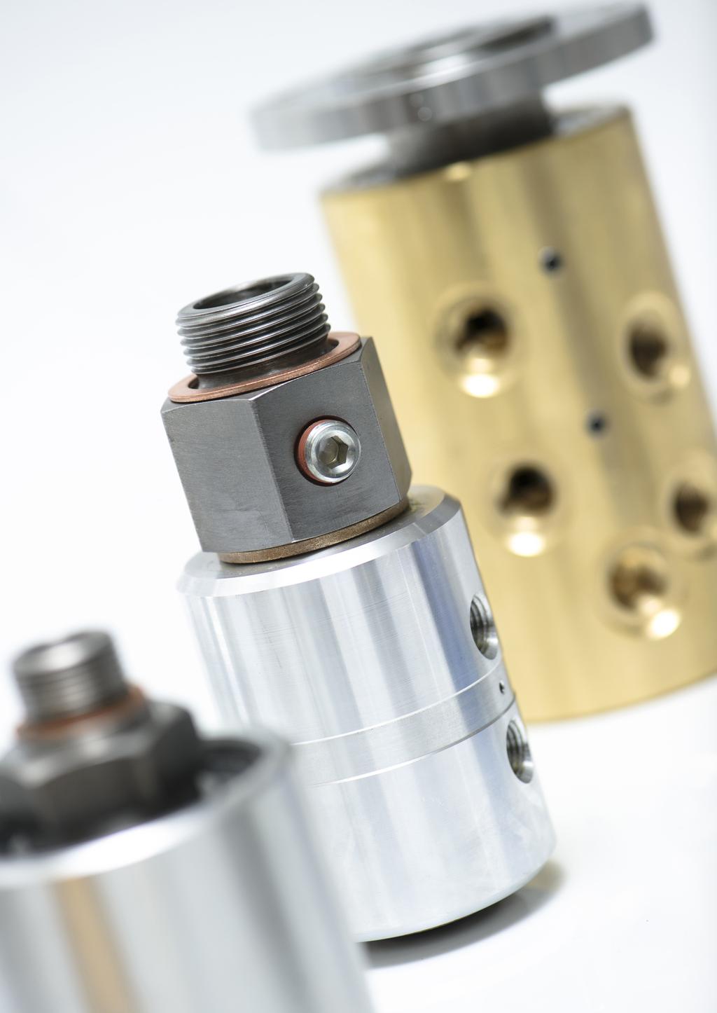
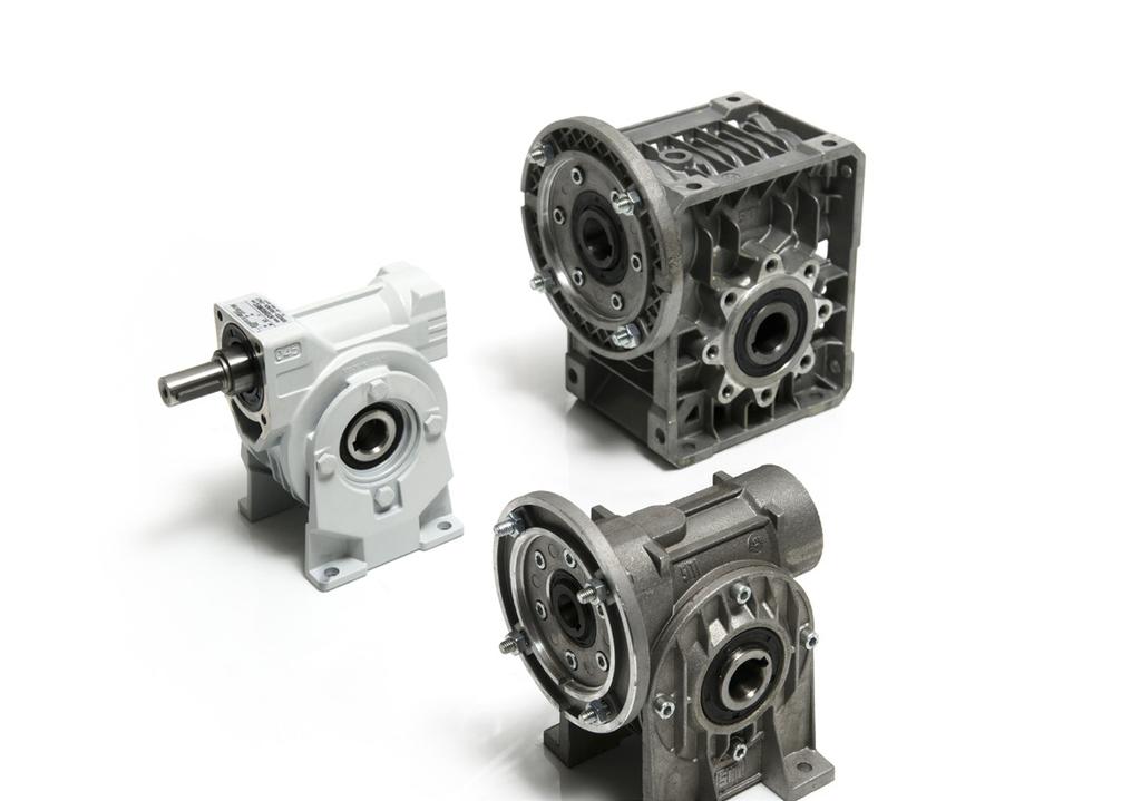
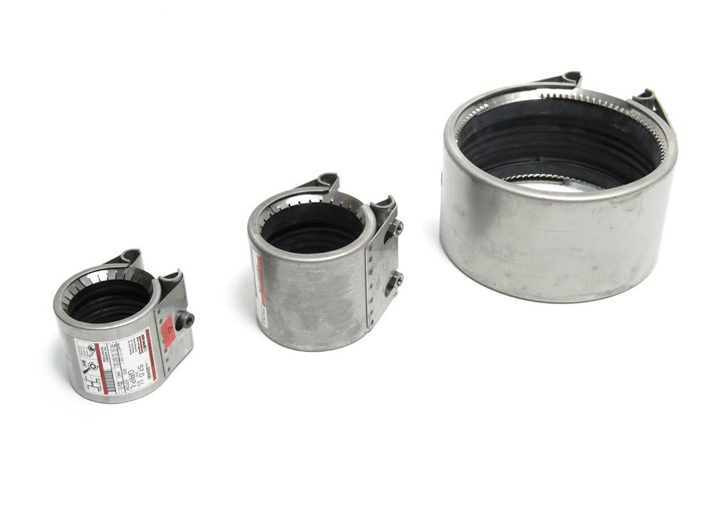
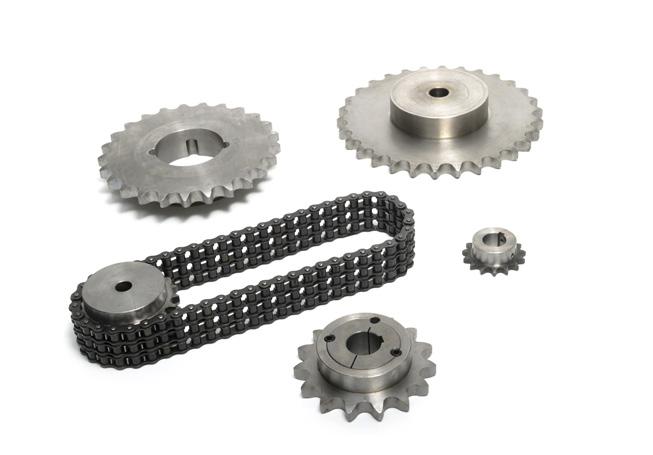
55 Voimansiirtokomponentit ja laitekokonaisuudet ovat meille tuttuja, sillä olemme yksi johtavista voimansiirtokomponenttien toimittajista Suomessa. Asiantuntijamme auttavat mielellään löytämään oikeat ratkaisut tarpeisiinne ja pystymme laajan tuotevalikoimamme ja kattavan varasto-ohjelman avulla nopeisiin toimituksiin. Edustamme kansainvälisesti tunnettuja valmistajia ja tuotemerkkejä tuotteiden ja toiminnan korkea laatu on yksi toimintamme kulmakivistä. Palvelemme teitä kaikissa voimansiirtoasioissanne yli neljänkymmenen vuoden kokemuksella. Solutions for power transmission
MADE IN GERMANY. Electromagnetic Technology
 MT MADE IN GERMANY Electromagnetic Technology KEB Automation KG 2 MAGNETTECHNIQUE All our efforts are directed towards the development, production and application of electromagnetic technology throughout
MAGNETTECHNIQUE. More than 30 years experience in the field of Electromagnetic technology. KEB Germany. KEB China. KEB America.
 GB MAGNETTECHNIQUE More than 30 years experience in the field of Electromagnetic technology KEB China KEB Japan All our efforts are directed towards the development, production and application of electromagnetic
MADE IN GERMANY. Electromagnetic Technology
 MADE IN GERMANY MT Electromagnetic Technology Safe braking and holding COMBISTOP H COMBISTOP D COMBISTOP T COMBISTOP Electromagnetically actuated dual-surface spring applied DC brakes for dry operation.
COMBIBOX. Program Schedule. with an energised to engage single sided clutch without brake... COMBIBOX 09
 COMBIBOX clutch-brake-combination 10 / 09 / 06 with an energised to engage single sided clutch / brake... COMBIBOX 10 with an energised to engage single sided clutch without brake... COMBIBOX 09 with an
COMBIBOX Program Schedule. Design. COMBIBOX Clutch-brake-combination type 10 / 09 / 06. Attachments input
 COMBIBOX Program Schedule COMBIBOX Clutch-brake-combination type 10 / 09 / 06 with an energised to engage single sided clutch / brake COMBIBOX 10 page 37 with an energised to engage single sided clutch
COMBIBOX. Program Schedule. Design. COMBIBOX clutch-brake-combination type 10 / 09 / 06. Attachments
 clutch-brake-combination 10 / 09 / 06 with an energised to engage single sided clutch / brake... 10 with an energised to engage single sided clutch without brake... 09 with an energised to engage single
COMBISTOP NEW. Spring applied brakes
 COMBISTOP NEW Spring applied brakes With manufacturing sites on three continents and a global sales network KEB ensures worldwide availability and support of the KEB COMBISTOP 38. This latest generation
Electromagnetic clutches and brakes INTORQ and INTORQ
 Electromagnetic clutches and brakes INTORQ 14.105 and INTORQ 14.115 7.5 480 Nm setting the standard Product information INTORQ electromagnetic clutches and brakes transmit the drive torque or braking torque
Brakes. KNOTT Electromagnetic Release Spring-Applied Dual-Surface Fail-Safe Brakes TYPE ERA, ERB, ERC ELECTROMAGNETIC
 Brakes ELECTROMAGNETIC KNOTT Electromagnetic Release Spring-Applied Dual-Surface Fail-Safe Brakes TYPE ERA, ERB, ERC www.knott.de We make your brake 1 KNOTT manufacture a wide range of electromagnetic
your reliable partner ROBA-stop K.800.V09.EN
 your reliable partner ROBA-stop K.800.V09.EN www..com your reliable partner Your Advantages When Using ROBA-stop ROBA-stop brakes attract customers because of their decided advantages in relation to operational
Electromagnetic clutch-brake combinations INTORQ
 Electromagnetic clutch-brake combinations INTORQ 14.800 14.867 7.5 120 Nm setting the standard 2 CBC en 5/2005 Contents Clutch-brake combinations Product information 4 Type code 6 Design selection 8 Overview
ROBATIC ROBA -quick ROBA -takt. Reliable coupling and braking.
 Reliable coupling and braking Equipment Technology Packaging Machinery Conveyors and Materials Handling Equipment Door drives Indexing tables ROBATIC ROBA -quick ROBA -takt www.mayr.de Electromagnetic
Permanent magnet brakes. Safety from the market leader. PM Line High Torque Line
 Permanent magnet brakes Safety from the market leader PM Line High Torque Line Industrial Drive Systems Die Welt von Kendrion Industrial Drive Systems Kendrion The brake experts As a solution provider,
Brakes ELECTROMAGNETIC. KNOTT Electromagnetic Single Disc Brakes TYPE EAA, EAR
 Brakes ELECTROMAGNETIC KNOTT Electromagnetic Single Disc Brakes TYPE EAA, EAR www.knott.de We make your brake KNOTT Electromagnetic Single Disc Brakes TYPE EAA, EAR 1 KNOTT manufacture a wide range of
Electromagnetically actuated clutches and brakes
 Electromagnetically actuated clutches and brakes General notes Dry-running/wet-running 4.03.00 Electrical circuits 4.03.00 Rectifier units 4.03.00 Coil connections 4.04.00 Spark quenching 4.04.00 Protection
Stromag Dessau. safety in motion PRODUCT CATALOGUE. NFF4F-LS Brake. for Slow-Running High Torque Drivelines, in harsh environment
 Stromag Dessau safety in motion PRODUCT CATALOGUE NFF4F-LS Brake for Slow-Running High Torque Drivelines, in harsh environment ENGINEERING THAT MOVES THE WORLD Applications Holding brake variations with
your reliable partner ROBA-stop -M K.891.V17.EN
 ROBA-stop -M K.89.V7.EN www..com Your Reliable Brake Easy installation Class of insulation F; 00 % duty cycle C US Short switching times Different torque variants due to variable equipment Completely enclosed
L1 (Standard Motor Length) L2 (Brake Motor Length)
 L2 (Brake Motor Length)") HepcoMotion Geared Motor Option The optional geared motor will be the preferred choice for many applications as it provides an excellent combination of power, accuracy, flexibility and value. HepcoMotion
HepcoMotion Geared Motor Option The optional geared motor will be the preferred choice for many applications as it provides an excellent combination of power, accuracy, flexibility and value. HepcoMotion
Installation and Operational Instructions for ROBATIC -clutch Types _.0 and _.0 Sizes 3 7
 Please read these Installation and Operational Instructions carefully and follow them accordingly! Ignoring these Instructions may lead to malfunction or to clutch failure, resulting in damage to other
Standard with cone bushing. Backlash-free Safety Clutch
 EAS -Compact ratchetting clutch/synchronous clutch The Backlash-free Safety Clutch for Standard with cone bushing Packaging Machinery Machine Tools Paper Machinery Indexing Drives Servo Motors EAS -NC
setting the standard BFK468 spring-applied brake The Performance Standard 100-2,400 Nm
 setting the standard BFK468 spring-applied brake The Performance Standard 100-2,400 Nm www.intorq.de We set the standards The INTORQ brand stands for reliable brake solutions of the highest standard. Whether
Accessories smart additions for efficiency and intelligent performance
 smart additions for efficiency and intelligent performance Metal bellows couplings Perfectionists you can count on Metal bellows couplings are designed for the highest requirements in servo drive technology.
Lenze. Drives with worm gearboxes 52.
 6 887 Lenze Drives with worm gearboxes 5. Lenze Drive Systems GmbH, Postfach 0 5, D-76 Hameln, Site: Groß Berkel, Hans-Lenze-Straße, D-855 Aerzen, Phone ++9 (0) 55 8-0, Telefax ++9 (0) 55 8- E-Mail: Lenze@Lenze.de
Motor mounted Brakes. Safety. Made in Germany.
 Motor mounted Brakes. Safety. Made in Germany. Motor mounted Brakes PINTSCH BUBENZER Content Spring Set Brakes Series 3-8 Spring Set Brake EFB-N 9-12 Spring Set Brake KFB 13-15 Accessories 17-23 Brake
ROBA -topstop. Brake systems for gravity loaded axes. ROBA-stop
 ROBA -topstop Brake systems for gravity loaded axes ROBA-stop The best choice for safe brakes www..com l Reliable protection in all operating modes l Maximum safety due to redundant systems and integrated
KTR Torque Limiters Overload Protection Systems
 KT Torque Limiters Overload Protection Systems UFLEX - Friction Disk - Zero Backlash Ball Detent KT SI - Ball/oller Bearing Style KT SI Compact - Zero Backlash Ball Detent Catalog Contents (Metric) Page
Lenze spring applied brakes
 Type BFK 458 N Spring applied, electromagnetic release Factory preset torque Simple, quick assembly Adjustable for wear Very robust Torques 2 to 600 Nm S1 continuous rated Static and dynamic braking No
Mönninghoff electromagnetic tooth clutches
 Mönninghoff electromagnetic tooth clutches High torque without slip in compact size Angular synchronisation of input to output possible Torque limiting and other special tooth options readily available
Focus on Sci. & Tech. Grasp Details
 Focus on Sci. & Tech. Grasp Details B Series Safety brake, adopts modular design and has multiple functions, which can facilitate super rapid response with its professionally designed for low power electromagnetic
your reliable partner ROBA-stop -M Electromagnetic safety brakes C US LR K.891.V16.EN
 ROBA-stop -M Electromagnetic safety brakes C US LR 0897 K.89.V6.EN www..com Your Reliable Brake Easy installation Class of insulation F; 00 % duty cycle C US Short switching times Different torque variants
POWER TRANSMISSION. Product range
 POWER TRANSMISSION Product range Product range Business Unit Power Transmission Since the firm was established in 1911 by Wilhelm Binder, the Power of Magnetism has always been the essential principle
Spring-applied brake INTORQ BFK458
 Spring-applied brake INTORQ BFK458 The versatile modular system 1.5 600 Nm setting the standard www.intorq.de BFK458 The modular system This modular system forms the basis for a product range that offers
Electromagnetic tooth clutch Type 546
 Electromagnetic tooth clutch Type 546 Characteristics and features high torque transfer despite compact dimensions positive-locking transmission of torque without slip engageable also at low relative speed
setting the standard Electromagnetic clutches and brakes INTORQ und Nm
 setting the standard Electromagnetic clutches and brakes INTORQ 14.105 und 14.115 7.5 480 Nm www.intorq.com We set the standards The INTORQ brand stands for reliable brake solutions with the highest product
TORQLIGHT SAFETY COUPLINGS
 LIGHTWEIGHT AND COMPACT single-position TOQLIGHT SAFETY COUPLINGS SEIES SL 10 700 Nm THE ULTIMATE COUPLING FOM 10 700 Nm SEIES SL DESIGN / FEATUES Extremely lightweight construction Up to 60 % weight reduction
your reliable partner ROBA-stop -silenzio K.896.V16.EN
 ROBA-stop -silenzio K.896.V6.EN www..com Expert know-how in development and design As the technological leader, mayr power transmission focuses on continuous further development. Today, highly qualified
Highest Performance: SPH Series
 Highest Performance: Series The series features helical gearing which brings a whole new level of power and precision to GAM s already extensive portfolio of gear reducer technology. With special attention
Installation and Operating Instructions for ROBA-stop -silenzio Type 896._3_. Sizes
 Please read and observe this Operating Instruction carefully! A possible malfunction or failure of the clutch and damage may be caused by not observing it. Table of contents: Page 1: - Table of contents
C-SERIES S-SERIES. Metric Machine Screw Jacks EMA LINEAR ACTUATORS
 C-SERIES S-SERIES Metric Machine Screw Jacks EMA LINEAR ACTUATORS Power Jacks has a proud engineering heritage dating from the earliest years of the 20th Century. A heritage that is about excellence: about
Installation and Operational Instructions for ROBATIC -clutch Type and Type Sizes 3 9
 Please read the Operational Instructions carefully and follow them accordingly! Ignoring these Instructions may lead to malfunctions or to clutch failure, resulting in damage to other parts. Contents:
Classic Line. Spring-applied single-disc / multiple-disc brake A A A00
 Classic Line Spring-applied single-disc / multiple-disc brake 77 600..A00 77 600..A15 77 100..A00 Classic Line Industrial Drive Systems Die Welt von Kendrion Industrial Drive Systems Kendrion The brake
The controllableollable Torque Limiting Clutch for
 The controllableollable Torque Limiting Clutch for Filling Machinery Printing Machinery Packaging Machinery Conveyors and Materials Handling Equipment pneumatic or electromagnetic clutch Controllable during
INDUSTRIAL DRIVE SYSTEMS ACTIVE BRAKE LINE. Electromagnetic single-surface brake E E00
 INDUSTRIAL DRIVE SYSTEMS ACTIVE BRAKE LINE Electromagnetic single-surface brake 86 111..E00 86 121..E00 ACTIVE BRAKE LINE Kendrion (Aerzen) GmbH, Deutschland Kendrion (Villingen) GmbH, Germany Kendrion
Shaft Couplings Flange-Couplings Rigid Shaft Couplings Flexible Couplings
 Shaft Couplings Flange-Couplings Rigid Shaft Couplings Flexible Couplings 44 Edition 2013/2014 RINGSPANN Registered Trademark of RINGSPANN GmbH, Bad Homburg 2 Table of Contents Flange-Couplings Page Flange-Couplings
Installation and Operating Instructions for ROBA-stop -silenzio Type 896. _. Sizes
 Please read and observe this Operating Instruction carefully! A possible malfunction or failure of the clutch and damage may be caused by not observing it Table of contents: Page1: - Table of contents
Catalog Mars Low voltage Brake motors
 Catalog Mars 2014 Low voltage Brake motors We provide motors, generators and mechanical power transmission products, services and expertise to save energy and improve customers processes over the total
Tooth Clutches. Series 5H and 55H-P Pressure Applied Tooth Clutch. Stationary Cylinder for Dry Operation or in Oil. Series 5H and 55H-P
 Series 5H and 55H-P Series 5H and 55H-P Pressure Applied Tooth Clutch Stationary Cylinder for Dry Operation or in Oil Features Tooth clutch gives positive drive with no slip Shielded bearings need no lubrication
LIGHTWEIGHT AND COMPACT. SERIES SL Nm. single-position multi-position. THE ultimate COUPLING from Nm
 LIGHTWEIGHT AND COMPACT L SAFETY COUPLINGS TOQLIGHT SEIES SL 5 700 Nm THE ultimate COUPLING from 5 700 Nm SEIES SL DESIGN / FEATUES Extremely lightweight construction Up to 60 % weight reduction in comparison
Installation and Operational Instructions for ROBA-stop Holding Brake Type _._
 Please read these Installation Instructions carefully and follow them accordingly! Ignoring these Instructions may lead to malfunctions or to brake failure, resulting in damage to other parts. Contents:
Electromagnetically actuated clutches and brakes. clutch / brake combined units, tooth clutches and spring-applied brakes
 왎 Electromagnetically actuated es and brakes / brake combined units, tooth es and spring-applied brakes Or tlinghaus Plates. Clutches. Brakes. Systems. Electromagnetically actuated es and brakes, /brake
8 BK brakes. 8.1 Description of BK brakes (CMP40 to CMP63) Description of BK brakes (CMP40 to CMP63)
 Description of BK brakes (CMP40 to CMP63)") 8 BK brakes Description of BK brakes (CMP0 to CMP6) 8 BK brakes 8. Description of BK brakes (CMP0 to CMP6) The mechanical brake is a holding brake implemented as a permanent magnet brake. The standard
8 BK brakes Description of BK brakes (CMP0 to CMP6) 8 BK brakes 8. Description of BK brakes (CMP0 to CMP6) The mechanical brake is a holding brake implemented as a permanent magnet brake. The standard
Backlash-free Metal Bellow Couplings
 Backlash-free Metal Bellow Couplings Edition 3/2008 pioneer in innovation GERWAH pioneer in innovation Future made by GERWAH. Your advantages: The GERWAH name is synonymous with development and manufacturing
Flexible pin & bush coupling
 Technical data KX-D Technical data Torque [Nm] NBR 80 Sh-A GJL Steel Dyn. torsion spring stiffness [Nm/rad] Max. speed Max. speed Rated Max. Vibratory [rpm] with Max. bore [mm] [rpm] with Max. bore [mm]
your reliable partner ROBA-stop -silenzio Stage and Elevator Brakes C US LR K.896.V14.EN
 ROBA-stop -silenzio Stage and Elevator Brakes C US LR 897 K.896.V4.EN www..com ROBA-stop -silenzio Reliable dual circuit brake in accordance with BGV C, EN 8 and other international standards Characteristics
Locking Assemblies & Locking Elements
 US 01 2016 Locking Assemblies & Locking Elements Partner for Performance www.ringfeder.com Welcome to your system supplier for every aspect of power transmission Today s RINGFEDER POWER TRANSMISSION GMBH
Hydraulic Caliper Disc Brakes SFRA 5
 BRAKE SYSTEMS FOR WIND ENERGY Rotor Brake (active) Hydraulic Caliper Disc Brakes SFRA 5 25 PINTSCH BUBENZER is certified according to DIN EN ISO 9001:2000 SFRA 5 (µ = 0,4) SFRA 5 (µ = 0,3) SFRA 5 (µ =
Ship & offshore. Safety.
 Ship & offshore. Safety. 2014 PINTSCH BUBENZER www.pintschbubenzer.com Content Hydraulic Disc Brakes B1 - B10 Electromagnetic Disc Brakes C1 - C19 Accessories CX1 - CX7 Brake Control Unit BCU2001 CX9 -
ELECTROMAGNETIC CLUTCH AND BRAKE UNITS
 -ACTUATED CLUTCHES AND BRAKES CLUTCH AND BRAKE UNITS Application Printing machinery, bookbinding machinery, woodworking machinery, semiconductor manufacturing equipment Connection and Release, Required
BEVEL GEAR UNITS ZZ-SERVOLINE
 BEVEL GEAR UNITS ZZ-SERVOLINE ZZ-SERVOLINE GEARBOX DESIGN AND FUNCTIONAL FEATURES Gear Ratios i= 3:1 i= 4:1 i= 5:1 i= 6:1 i= 8:1 i= 10:1 i= 12:1 i= 15:1 Spiral Bevel Gear KLINGELNBERG tooth system Hypoid
RIGHT ANGLE DRIVES TG Series
 RIGHT ANGLE DRIVES TG Series Right Angle Fixed Index Drives TG Series The rotary index table transforms a constant input drive motion into an intermittent output drive motion. The intermittent drive motion
D58 Series Brake Instructions
 D58 Series Brake Instructions 4740 W. Electric Avenue Milwaukee, WI 53219 414/672-7830 FAX 414/672-5354 www. dingsbrakes.com Safety information 2 Safety information 2.1 Persons responsible for the safety
ROBATIC, ROBA -quick ROBA -takt
 ROBATIC, ROBA -quick ROBA -takt Electromagnetic Clutches and Brakes, Clutch Brake Units www..de High torque capacity Low wear Compact construction Easy assembly and maintenance K.500.V08.GB your reliable
Product Information PI Disk-type tool turret
 Product Information PI 21.3 Disk-type tool turret without tool drive Series with tool drive Series 0.5.460.4xx 0.5.456.4xx (axial) 0.5.450.4xx (radial) 2017-05-31 PI 21.3 3 Contens Table of Contens Turret
QUICK-ACTING JAW CHANGE SYSTEM
 QUICK-ACTING JAW CHANGE SYSTEM The RÖHM key bar chucks with quick-acting jaw change system convince in two ways. On the one hand the jaws can be quickly and easily turned, changed or offset over the entire
Brake Systems for Mining. Safety. Made in Germany.
 Brake Systems for Mining. Safety. Made in Germany. 2014 PINTSCH BUBENZER www.pintschbubenzer.com Content Thruster Disc Brakes A7 - A13 Pneumatic Disc Brakes J1 - J8 Hydraulic Disc Brakes B1 - B21 Electromagnetic
Backlash-free safety couplings. Backlash-free safety couplings. Product information. Optimal safety has a name: Guaranteed by two systems:
 ;;Engaged ;;Engaged Backlash-free safety couplings Product information Optimal safety has a name: Backlash-free safety couplings Guaranteed by two systems: ;;;; Locking Locking element - cylinder roller
Selection Tool. on the Internet at in the section MÄDLER -Tools. Other sizes and designs on request. Connecting Shafts Page 766
 Couplings Overview Friction Clutches Friction Clutches Type B Axial Arrangement Friction Clutches Type C Transversal Flexibility Sliding Hubs with Torsionally-Flexible Coupling Multi-Disk Friction Clutches
NEW. Cone Clamping Elements Trantorque Keyless Locking Devices for very small diameters from 3 mm. E03.050e
 Cone Clamping Elements Trantorque Keyless Locking Devices for very small diameters from 3 mm NEW E03.050e Backlash free positioning Excellent concentricity Quick mounting by central clamping nut Issue
EJP SERIES Right-angle Worm
 EJP SERIES T he EJP series is ideal for demanding applications requiring high efficiency, torsional rigidity and zero backlash. It s lightweight, black anodized aluminum housing and dual input/output seals
Installation and Operational Instructions for ROBA-stop -M Brake Type 891. _. _ Sizes 2 500
 Please read these Operational Instructions carefully and follow them accordingly! Ignoring these Instructions may lead to malfunctions or to brake failure, resulting in damage to other parts. These Installation
Flexible Couplings 44
 Flexible Couplings 44 RINGSPANN Registered Trademark of RINGSPANN GmbH, Bad Homburg MTY (81) 83 54 10 18 Why RINGSPANN Flexible Couplings? No connection of shafts without clutches It is a well-known fact
ELECTROMAGNETIC DISC BRAKES H2SP SERIES WITH CONSTANT BRAKING TORQUE
 ELECTROMAGNETIC DISC BRAKES SERIES WITH CONSTANT BRAKING TORQUE K-EN--20151203 TD 223a Spring actuated and electromagnetically released disk brake type powered by direct current. Designed for braking rotating
AC Line. Spring-applied single-disc brake A H E00 / E00
 AC Line Spring-applied single-disc brake 73 341..A00 73 431..H00 73 241..E00 / 73 245..E00 AC Line Industrial Drive Systems Die Welt von Kendrion Industrial Drive Systems Kendrion the brake experts As
Armature Actuated Brakes RoHS Compliant- meets the requirements of the Restriction of Hazardous Substances Directive
 RoHS Compliant meets the requirements of the Restriction of Hazardous Substances Directive DirectActing, DC brakes in torque ratings from 3 lbft to 300 lbft (4 Nm to 400 Nm) of torque. Dings Armature Actuated
3-phase stepping motors
 General Series of Features from Berger Lahr are: Powerful because the optimised internal geometry results in a high power intensity, meaning up to 50 % more torque than standard stepping motors of comparable
Brakes. KNOTT Electromagnetic Release Spring-Applied Dual-Surface Spring applied Brakes ELECTROMAGNETIC
 Brakes ELECTROMAGNETIC KNOTT Electromagnetic Release Spring-Applied Dual-Surface Spring applied Brakes TYPE ERG www.knott.de We make your brake KNOTT Electromagnetic Release Spring-Applied Dual-Surface
Service Instructions BZFM V7
 Service Instructions BZFM V7 Electromagnetic- Double - Face Spring - Applied Brake These operating instructions are intended to enable the user to operate the product safely and effectively, to use it
Inkoturn couplings. INKOMA - GROUP Couplings. Product description. Inkoturn couplings IKT. FRANCIS AND FRANCIS Ltd.
 Product description The INKOM Inkoturn coupling (IKT) is a flexible coupling with high torsional rigidity, which has been developed for applications requiring high speed and where shaft is present. INKOM
RIGIFLEX -N RADEX -N. Steel laminae coupling. Steel laminae coupling. You will find continuously updated data in our online catalogue at
 117 Table of contents 117 Coupling selection steel laminae coupling 119 Description of coupling 121 General information 122 Types and applications 123 Technical data 124 Standard types 126 Special types
Modular Explosion Proof Brakes. IECLine rev 0
 Modular Explosion Proof Brakes IECLine 2013 rev 0 Application example Standard B5 motor + VIS brake Standard B5 motor + VIS brake + gearbox unit Main Characteristics -PATENT pending design and concept
Altra Industrial Motion Warner Electric TB Wood s Boston Gear Altra Industrial Motion - Asia Pacific and Africa Servo Motor Brakes
 Servo Motor Brakes A variety of brake solutions to meet specific servomotor application requirements For over 30 years, Matrix has designed and manufactured more than 700 variants of spring-applied, electromagnetic
W22 Brake Motor Three-phase Electric Motor
 Motors Automation Energy Transmission & Distribution Coatings W22 Brake Motor Three-phase Electric Motor African Market -- Visual index Main motor parts 1 Sealing system 8 Fan 2 Endshields 9 Bridge rectifier
Performance Plus: Spiral Bevel Series
 Performance Plus: Spiral Bevel Series GAM Perfomance Plus Miniature Spiral Bevel Gearboxes The VP Series Performance Plus Miniature Bevel Gearboxes pack high performance in a small package with the highest
setting the standard Electromagnetic clutch-brake combinations INTORQ Nm
 setting the standard Electromagnetic clutch-brake combinations INTORQ 14.800 7.5 120 Nm www.intorq.com We set the standards The INTORQ brand stands for reliable brake solutions with the highest product
Chuck size
 URO-T / URO A Exterior form incl. splash water edge URO-T Technical features RÖHM URO-T Manual chucks: 20% higher clamping forces Chuck body stiffer (guarantees precision at higher loads) Surface of chuck
Demag KB conical-rotor brake motors. Drives with unique principle
 Demag KB conical-rotor brake motors Drives with unique principle 37468 Demag KB conical rotor brake motors: Demag KB conical rotor brake motors offered by Demag Cranes & Components feature a unique principle:
HB Hysteresis Brakes and MHB Matched Brakes
 Data Sheet HB s and MHB s Features Torque up to 3500 oz in Speed up to 20,000 rpm Power up to 2400 W Available in Metric or English dimensions Torque independent of speed Long, maintenance-free life Operational
Precision Modules PSK. The Drive & Control Company
 Precision Modules PSK The Drive & Control Company 2 Bosch Rexroth Coporation Precision Modules PSK R310A 2414 (2008.07) Linear Motion and Assembly Technologies Ball Rail Systems Roller Rail Systems Linear
Linear Drive with Ball Screw Drive Series OSP-E..SB
 Linear Drive with Ball Screw Drive Series OSP-E..SB Contents Description Data Sheet No. Page Overview 1.30.001E 47-50 Technical Data 1.30.002E-1 to 5 51-55 Dimensions 1.30.002E-6, -7 56-57 Order instructions
Precision on the highest level
 6 - line Precision on the highest level The series is the standard Neugart inline high precision planetary gearhead for applications with very high precision requirements. Whether high torque density,
POWER GEAR. The HighSpeed bevel gearbox.
 MS-Graessner GmbH & Co. KG THE GEAR COMPANY POWER GEAR The HighSpeed bevel gearbox HS www.graessner.de Nothing but highlights! Designed for special requirements no adaption, no compromises: There are decades
alpha Value Line - NPS Sizing and Technical Data Efficient Flexible Reliable
 alpha Value Line - NPS Sizing and Technical Data Efficient Flexible Reliable alpha Value Line NP NPS NPL NPT NPR Ratios 3-100 Torsional backlash [arcmin] 8 Output type Smooth output shaft Grooved output
Compact Modules. with ball screw drive and toothed belt drive R310EN 2602 ( ) The Drive & Control Company
 The Drive & Control Company") with ball screw drive and toothed belt drive R310EN 2602 (2007.02) The Drive & Control Company Bosch Rexroth AG Linear Motion and Assembly Technologies Ball Rail Systems Roller Rail Systems Linear Bushings
with ball screw drive and toothed belt drive R310EN 2602 (2007.02) The Drive & Control Company Bosch Rexroth AG Linear Motion and Assembly Technologies Ball Rail Systems Roller Rail Systems Linear Bushings
ZF Friedrichshafen AG Special Driveline Technology. Hysteresis brakes Hysteresis clutches Electronic control unit
 ZF Friedrichshafen G Special Driveline Technology Hysteresis brakes Hysteresis clutches Electronic control unit 2 ZF-Servoplan CG Compact Gearbox ZF-Duoplan 2K Two-speed Gearboxes ZF-Ecolift Elevator Gearboxes
Installation and Operating Instructions for ROBA-stop -silenzio Type 896. _. Sizes
 Please read the Operational Instructions carefully and follow them accordingly! Ignoring these Instructions can lead to lethal accidents, malfunctions, brake failure and damage to other parts. These Installation
Torsionally Stiff Steel Lamina Couplings. innovative quality products. optimal cost-performance ratio. certified according to DIN ISO 9001
 RGFLEX Torsionally Stiff Steel Lamina Couplings features: innovative quality products large-scale service optimal cost-performance ratio certified according to DN SO 0 worldwide net of distribution www.ktr.com
Locking elements. Technical information
 Technical information ocking elements.principle of operation. These parts operate on the basis of an interference fit between two conical rings crewed together. The outer ring expands and exerts a pressure
Automation for a Changing World. Delta Planetary Gearbox PS High Precision Series.
 Automation for a Changing World Delta Planetary Gearbox PS High Precision Series www.deltaww.com PS Series Planetary Gearbox PS High Precision Series The PS Series Planetary Gearbox features many advantages
Electromagnetic brake systems for hoists
 Electromagnetic brake systems for hoists setting the standard www.intorq.de Electromagnetic brake systems for hoists Our products have been setting standards for years, and meet the highest performance
Highest Performance: Dyna Series
 Highest Performance: Dyna Series GAM can. If you don t see exactly what you need, let us know. We can modify the Dyna Series gearboxes to meet your needs. Page provides a list of commonly requested modifications