Locking Assemblies & Locking Elements
|
|
|
- Stewart Richards
- 6 years ago
- Views:
Transcription


1 US Locking Assemblies & Locking Elements Partner for Performance


2 Welcome to your system supplier for every aspect of power transmission Today s RINGFEDER POWER TRANSMISSION GMBH was founded in 1922 in Krefeld, Germany as patent exploitation company for Friction Springs. Today we are a global supplier of top-quality products for the power transmission- and damping technology industries. RINGFEDER POWER TRANS- MISSION is one of the leading companies in selected market niches. Through our sustainable, organic growth, targeted acquisitions and attentive proximity to our customers, we are constantly supplementing and developing our range of products in cooperation with our customers and deliver service for the future. Beyond that, RINGFEDER POWER TRANS- MISSION is one of the prime addresses in regard to technical know-how for our discerning customers. 2


3 Mars Rover: Courtesy NASA/ JPL-Caltech Our world-renowned German brands RINGFEDER, TSCHAN and GERWAH stand for customer-oriented solutions that fulfil the highest requirements and guarantee our customers a trouble-free system operation. Under the brand name ECOLOC we offer reliable products off the shelf. The brand RINGFEDER is world s leading in the sector of locking devices and damping technology. The GERWAH brand stands for torsionally rigid, elastic couplings as well as safety couplings in the lower torque range, whereas TSCHAN stands for non-shiftable elastic, highly-elastic and torsionally rigid shaft couplings in the higher torque range. The ECOLOC brand includes cost-efficient alternatives from the premium range available for standard use. Hence, the product portfolio comprises high-quality products with the best cost-benefit ratio, covering all aspects of power transmission. 3
4 Locking Assemblies Characteristics... Page 8 RINGFEDER RfN 7012-IN/ Page 10 RINGFEDER RfN Page 16 RINGFEDER RfN IN/ Page 20 RINGFEDER RfN IN/ Page 24 RINGFEDER RfN Page 28 RINGFEDER RfN Page 30 RINGFEDER RfN Page 32 Content RINGFEDER RfN Page 34 Locking Assemblies with central lock nut RINGFEDER RfN Page 38 RINGFEDER RfN Page 40 RINGFEDER RfN Page 42 RINGFEDER RfN 7090 stainless steel... Page 44 Locking Assemblies for bending loads Characteristics... Page 48 RINGFEDER RfN Page 50 RINGFEDER RfN Page 54 RINGFEDER RfN Page 56 Content RINGFEDER RfN Page 58 RINGFEDER RfN Page 60 All technical details and information are non-binding and cannot be used as a basis for legal claims. The user is obligated to determine whether the represented products meet his requirements. We reserve the right at all times to carry out modifications in the interests of technical progress. Upon the issue of this catalogue all previous brochures and questionnaires on the products displayed are no longer valid. 4


5 Content Locking Elements Characteristics... Page 64 RINGFEDER RfN Page 66 RINGFEDER RfN 8006 GSA... Page 70 Content Locking Assemblies STAINLESS STEEL Characteristics... Page 74 RINGFEDER RfN 7012-IN/ Page 76 RINGFEDER RfN Page 80 RINGFEDER RfN Page 82 RINGFEDER RfN Page 84 Locking Elements RINGFEDER RfN Page 86 Special Solutions Special Locking Assemblies... Page 88 Calculation of hub and shaft Page 92 Installation and removal instructions Locking Assemblies... Page 94 Locking Elements... Page 108 Content 5
6 RINGFEDER Locking Assemblies 6

7 RfN 7012 RfN RfN RfN RfN 7014 RfN RfN RfN
8 RINGFEDER Locking Assemblies Characteristics Inexpensive manufacture the large tolerances that are possible and the simple turning process guarantee inexpensive manufacture. Simple installation only a few screws need to be tightened, alignment to precise angles between the hub and shaft is possible in any position, no fitting work is required. Simple dismantling RINGFEDER Locking Assemblies are fitted with threaded extraction holes, so that no additional auxiliary equipment is necessary, series RfN 7012 is self-releasing. Large constant reverse-torsion fatigue strength shaft and hub are ungrooved, so that there is no weakening of these components. Shaft and hub can be designed to be considerably smaller (light, cost and space-saving design possible). No danger of deflection RINGFEDER Locking Assemblies are absolutely backlashfree. Effect similar to overload protection after the set frictional connection force has been exceeded the Locking Assemblies simply slide. Valuable machine parts are protected. The Locking Assemblies are subject to the same laws as any other connection with force transmission by friction - not suitable as sliding clutch. Completely maintenance-free no follow-up costs. 8
9 Explanations to tables Basic dimensions when screws are not tightened d d D D B1 L L 1 L 3 L 4 T F ax p W p N n Sc D G SW T A = Inner diameter (decimal notation) = Inner ring diameter = Outer diameter = Collar outer diameter = Overall length = Overall length without screws = Width of inner ring = Installation length up to collar = Transmissible torque at given T A = Transmissible axial force = Surface pressure on shaft at given T A = Surface pressure on hub at given T A = Quantity of screws = Thread = Wrench size = Max. tightened torque of the clamping screws D N min = Min. hub outer diameter depending of the given hub yield point (Rp 0,2 ) T max Gw = Maximum transmissible torque = Weight 9

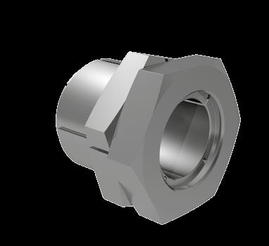
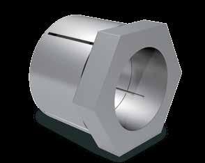
10 RINGFEDER Locking Assemblies RfN 7012-IN L N 2 L 3 ø DN Characteristics As the industry standard, the RfN 7012/RfN 7012-IN Locking Assembly is suitable for most applications. Transmission of high loads up to 4 RfN 7012/RfN IN Locking Assemblies can be used in series, the transmissible torques and axial forces are added. (Please contact our specialists for assistance). Locking Assembly RfN 7012 Location Calculation of hubs see on page (Calculation possible for other hub forms in our calculation program) L L 1 L 3 Bending moment and radial loads Combined loads can be transmitted. (Please contact our specialists for assistance). d D Simplified manufacture RfN 7012/RfN 7012-IN Locking Assemblies can bridge large clearances without the loss of transmission values. Low risk to contamination During the tightening process the functional surfaces of the device are under pressure, sufficient enough to keep contaminants out, thereby preserving the integrity of the device. Locking Assembly RfN 7012 Dimensions Adjustable transmission values The screw tightening torque can be varied, thus allowing for different torque transmission values. RfN 7012/RfN 7012-IN Locking Assemblies can be tightened and released repeatedly. Example applications: Sprockets, gears, coupling hubs, conveyor pulleys, idler wheels, sheaves Locking Assembly RfN 7012 Belt pulley 10
11 Locking Assembly dimensions Transmissible torques Surface pressure Locking screws D N min at or axial forces ISO R p0,2 Shaft Hub d d x D L L 1 L 3 T F ax p W p N n Sc D G SW T A Gw D HG [N/mm 2 ] inch inch inch ft-lbs lbs psi pcs. mm ft-lbs lbs inch inch /4 x M 6 x x M 6 x /8 x M 6 x /16 x M 6 x /4 x M 6 x /8 x M 6 x /16 x M 6 x /2 x M 6 x /8 x M 8 x /16 x M 8 x /4 x M 8 x /8 x M 8 x /16 x M 8 x x M 8 x /8 x M 8 x /16 x M 8 x /4 x M 8 x /8 x M 8 x /16 x M 8 x /2 x M 8 x /16 x M 8 x /8 x M 10 x /16 x M 10 x /4 x M 10 x /8 x M 10 x /16 x M 10 x x M 10 x /8 x M 10 x /4 x M 10 x /8 x M 10 x /16 x M 10 x /2 x M 10 x /4 x M 10 x /16 x M 12 x x M 12 x /16 x M 12 x /2 x M 12 x /16 x M 12 x x M 12 x /2 x M 12 x x M 12 x /2 x M 14 x x M 14 x /2 x M 14 x /8 x M 14 x Explanations to tables: Page 9 To continue see next page RfN 7012-IN 11
12 RINGFEDER Locking Assemblies RfN 7012 L N 2 L 3 ø DN Locking Assembly RfN 7012 Location Calculation of hubs see on page (Calculation possible for other hub forms in our calculation program) L L 1 L 3 d D Locking Assembly RfN 7012 Dimensions 12
13 Locking Assembly dimensions Transmissible torques Surface pressure Locking screws D N min at or axial forces ISO Rp 0,2 Shaft Hub d x D d x D L L 1 L 3 T F ax p W p N n Sc D G T A Gw [N/mm 2 ] T max mm inch inch ft-lbs lbs psi pcs. ft-lbs lbs inch ft-lbs 19 x x M 6 x x x M 6 x x x M 6 x x x M 6 x x x M 6 x x x M 6 x x x M 6 x x x M 6 x x x M 6 x x x M 6 x x x M 6 x x x M 8 x x x M 8 x x x M 8 x x x M 8 x x x M 8 x x x M 8 x x x M 8 x x x M 10 x x x M 10 x x x M 10 x x x M 10 x x x M 10 x x x M 10 x x x M 12 x x x M 12 x x x M 12 x x x M 12 x x x M 12 x x x M 12 x x x M 12 x x x M 14 x x x M 14 x x x M 14 x x x M 14 x x x M 16 x x x M 16 x x x M 16 x x x M 18 x x x M 18 x x x M 20 x x x M 20 x x x M 22 x x x M 22 x x x M 22 x x x M 22 x x x M 24 x x x M 24 x x x M 24 x x x M 24 x x x M 24 x Explanations to tables: Page 9 To continue see next page RfN
14 RINGFEDER Locking Assemblies RfN 7012 Characteristics Slimmest design, especially suitable for applications where space is limited. The not self-centering Locking Assembly RfN 7012 compensates small tolerance deviations and compensates small mounting errors. Large transmittable forces and moments several Locking Assemblies RfN 7012 can be placed one behind the other. The transmissible torque and axial forces are added - please take in this respect consulting with our technical experts. Bending moment and radial loads combined loads can be transmitted. (Please contact our technical department for assistance). Easy installation Locking Assemblies RfN 7012 can bridge large clearances without the loss of transmission values. Low risk to contamination during the tightening process the functional surfaces of the device and connection are pressed together generating a surface pressure that does not allow the ingress of contamination. Free from wear the Locking Assembly RfN 7012 works without moving parts on shaft and hub, through this, abrasive wear and backlash are avoided. Thus, RfN 7012 can be repeatedly clamped and released. Example applications: Chain wheels, levers, pulleys, slip-on gear mechanisms, belt drums, running wheels, cable sheaves 14
15 Locking Assembly dimensions Transmissible torques Surface pressure Locking screws D N min at or axial forces ISO Rp 0,2 Shaft Hub d x D d x D L L 1 L 3 T F ax p W p N n Sc D G T A Gw [N/mm 2 ] T max mm inch inch ft-lbs lbs psi pcs. ft-lbs lbs inch ft-lbs 540 x x M 24 x x x M 24 x x x M 24 x x x M 24 x x x M 24 x x x M 24 x x x M 24 x x x M 24 x x x M 24 x x x M 24 x x x M 24 x x x M 24 x x x M 24 x x x M 24 x x x M 24 x x x M 24 x x x M 24 x x x M 24 x x x M 24 x x x M 24 x x x M 24 x x x M 24 x x x M 24 x x x M 24 x Ordering example: RfN 7012 Series d D RfN Explanations to tables: Page 9 More sizes on request Mounting of Locking Assembly The Locking Assemblies are supplied slightly oiled and ready-to-use. The values for T, F ax, p W and p N apply to Locking Assemblies in delivery condition. Surface finishes For shafts and hub bores R a 3,2 µm Tolerances We recommend the following mounting tolerances Shaft: k9-h9; Hub: N9-H9 Max. permissible: Shaft: k11-h11; Hub: N11-H11 To avoid excessive deformations of the relatively thick-walled thrust rings, the Locking Assembly should be located as symmetrically as possible between shaft and hub bore. If the shaft is smaller than nominal d, the bore should exceed nominal D to the same extent and vice versa. The concentricity quality is determined by the direct centering between shaft and hub. Arrangement of several Locking Assemblies RfN 7012 If several Locking Assemblies are to be installed the transmission values of the table can be added, when the Locking Assemblies are located within a distance of 4 L. Change of screw tightening torques The Locking Assemblies are equipped with 12.9 grade screws. A reduction of the screw tightening torque is possible. The lowest allowable screw tightening torque results from the multiplication of the T A -value by 0.5. There is an approximate linear relationship between T, T A, F ax, p W and p N. Auxiliary threads To facilitate removal, the front thrust rings have auxiliary threads. RfN
16 RINGFEDER Locking Assemblies RfN L N 2 L 3 ø DN Locking Assembly RfN Location Calculation of hubs see on page (Calculation possible for other hub forms in our calculation program) L L 1 L 3 d D Locking Assembly RfN Dimensions 16
17 Locking Assembly dimensions Transmissible torques Surface pressure Special locking screws D N min at or axial forces Rp 0,2 Shaft Hub d x D d x D L L 1 L 3 T F ax p W p N n Sc D G T A Gw [N/mm 2 ] T max mm inch inch ft-lbs lbs psi pcs. ft-lbs lbs inch ft-lbs 100 x x M 12 x x x M 12 x x x M 12 x x x M 12 x x x M 12 x x x M 12 x x x M 12 x x x M 14 x x x M 14 x x x M 14 x x x M 14 x x x M 16 x x x M 16 x x x M 16 x x x M 18 x x x M 18 x x x M 20 x x x M 20 x x x M 22 x x x M 22 x x x M 22 x x x M 22 x x x M 24 x x x M 24 x x x M 24 x x x M 24 x x x M 24 x x x M 24 x x x M 24 x x x M 24 x x x M 24 x x x M 24 x x x M 24 x x x M 24 x x x M 24 x x x M 24 x x x M 24 x x x M 24 x x x M 24 x x x M 24 x x x M 24 x Ordering example: RfN Series d D RfN Explanations to tables: Page 9 More sizes on request RfN
18 RINGFEDER Locking Assemblies RfN Characteristics Slimmest design, especially suitable for applications where space is limited. The not self-centering Locking Assembly RfN compensates small tolerance deviations and compensates small mounting errors. Large transmittable forces and moments several Locking Assemblies RfN can be placed one behind the other. The transmissible torque and axial forces are added - please take in this respect consulting with our technical experts. Bending moment and radial loads combined loads can be transmitted. (Please contact our technical department for assistance). Easy installation Locking Assemblies RfN can bridge large clearances without the loss of transmission values. Low risk to contamination during the tightening process the functional surfaces of the device and connection are pressed together generating a surface pressure that does not allow the ingress of contamination. Free from wear the Locking Assembly RfN works without moving parts on shaft and hub, through this, abrasive wear and backlash are avoided. Thus, RfN can be repeatedly clamped and released. Example applications: Chain wheels, levers, pulleys, slip-on gear mechanisms, belt drums, running wheels, cable sheaves 18

19 Mounting of Locking Assembly The Locking Assemblies are supplied slightly oiled and readyto-use. The values for T, F ax, p W and p N apply to Locking Assemblies in delivery condition. Surface finishes For shafts and hub bores R a 3,2 µm Tolerances We recommend the following mounting tolerances Shaft: k9-h9; Hub: N9-H9 Max. permissible: Shaft: k11-h11; Hub: N11-H11 To avoid excessive deformations of the relatively thickwalled thrust rings, the Locking Assembly should be located as symmetrically as possible between shaft and hub bore. If the shaft is smaller than nominal d, the bore should exceed nominal D to the same extent and vice versa. The concentricity quality is determined by the direct centering between shaft and hub. Arrangement of several Locking Assemblies RfN If several Locking Assemblies are to be installed the transmission values of the table can be added when the Locking Assemblies are located within a distance of 4 L. Change of screw tightening torques The Locking Assemblies are equipped with 12.9 grade screws. A reduction of the screw tightening torque is possible. The lowest allowable screw tightening torque results from the multiplication of the T A -value by 0.5. There is an approximate linear relationship between T, T A, F ax, p W and p N. Auxiliary threads To facilitate removal, the front thrust rings have auxiliary threads. RfN
20 RINGFEDER Locking Assemblies RfN IN L N 2 L 3 ø DN Characteristics Excellent concentricity and very easy to dismantle these Locking Assemblies provide particularly good concentricity between the clamped parts. The flange is reinforced at the critical point. This prevents a bending and lifting of the inner ring during installation and therefore a good dismantling is ensured. High rotation speed the Locking Assemblies remain true-toform during assembly and so they are suitable in applications with higher rotational speeds. High radial loads the material strength of the RfN 7013 Locking Assemblies makes them especially suitable for applications with high radial loads. Example applications: Locking Assembly RfN Location / Calculation of hubs see on Page Calculation possible for other hub forms in our calculation program d L L 1 Locking Assembly RfN Dimensions L3 D Crane running wheels, couplings, gear wheels, flywheels, fan wheels Locking Assembly RfN Gear wheels Calculation possible for other hub forms in our calculation program 20
21 Locking Assembly dimensions Transmissible torques Surface pressure Locking screws D N min at or axial forces ISO R p0,2 Shaft Hub d d x D L L 1 L 3 T F ax p W p N n Sc D G T A Gw [N/mm 2 ] inch inch inch ft-lbs lbs psi pcs. ft-lbs lbs inch x M 6 x /16 x M 6 x /4 x M 6 x /8 x M 6 x /16 x M 6 x /2 x M 6 x /8 x M 8 x /4 x M 8 x /8 x M 8 x /16 x M 8 x x M 8 x /8 x M 8 x /16 x M 8 x /4 x M 8 x /8 x M 8 x /16 x M 8 x /2 x M 8 x /16 x M 8 x /4 x M 10 x /8 x M 10 x /16 x M 10 x x M 10 x /8 x M 10 x /16 x M 10 x /2 x M 10 x /4 x M 10 x /16 x M 10 x x M 10 x Ordering example: RfN IN Series Size RfN IN 1 15/16 Explanations to tables: Page 9 More sizes on request Mounting of Locking Assembly The Locking Assemblies are supplied slightly oiled and readyto-use. The values for T, F ax, p W and p N apply to Locking Assemblies installed in the delivery condition. Surface finishes For shafts and hub bores R a 1,6 µm Tolerances We recommend the following mounting tolerances Shaft: h8; Hub: H8 Change of screw tightening torques A change of the T A -values given in the above table is inadmissible. RfN IN 21
22 RINGFEDER Locking Assemblies RfN L N 2 L 3 ø DN Characteristics Excellent concentricity and very easy to dismantle these Locking Assemblies provide particularly good concentricity between the clamped parts. The flange is reinforced at the critical point. This prevents a bending and lifting of the inner ring during installation and therefore a good dismantling is ensured. High rotation speed the Locking Assemblies remain true-toform during assembly and so they are suitable in applications with higher rotational speeds. High radial loads the material strength of the RfN 7013 Locking Assemblies makes them especially suitable for applications with high radial loads. Example applications: Locking Assembly RfN Location / Calculation of hubs see on Page Calculation possible for other hub forms in our calculation program d L L 1 Locking Assembly RfN Dimensions L3 D Crane running wheels, couplings, gear wheels, flywheels, fan wheels Locking Assembly RfN Gear wheels Calculation possible for other hub forms in our calculation program 22
23 Locking Assembly dimensions Transmissible torques Surface pressure Locking screws D N min at or axial forces ISO Rp 0,2 Shaft Hub d x D d x D L L 1 L 3 T F ax p W p N n Sc D G T A Gw [N/mm 2 ] T max mm inch inch ft-lbs lbs psi pcs. ft-lbs lbs inch ft-lbs 19 x x M 6 x x x M 6 x x x M 6 x x x M 6 x x x M 6 x x x M 6 x x x M 6 x x x M 6 x x x M 6 x x x M 6 x x x M 6 x x x M 8 x x x M 8 x x x M 8 x x x M 8 x x x M 8 x x x M 8 x x x M 8 x x x M 10 x x x M 10 x x x M 10 x x x M 10 x x x M 10 x x x M 10 x x x M 10 x x x M 10 x x x M 10 x x x M 12 x x x M 12 x x x M 12 x Ordering example: RfN Series d D RfN Explanations to tables: Page 9 More sizes on request Mounting of Locking Assembly The Locking Assemblies are supplied slightly oiled and readyto-use. The values for T, F ax, p W and p N apply to Locking Assemblies installed in the delivery condition. Surface finishes For shafts and hub bores R a 1,6 µm Tolerances We recommend the following mounting tolerances Shaft: h8; Hub: H8 Change of screw tightening torques A change of the T A -values given in the above table is inadmissible. RfN
24 RINGFEDER Locking Assemblies RfN IN L N 2 L 3 ø DN Characteristics Locking Assembly RfN Location / Calculation of hubs see on Page Calculation possible for other hub forms in our calculation program Excellent concentricity and very easy to dismantle these Locking Assemblies provide particularly good concentricity between the clamped parts. The flange is reinforced at the critical point, preventing bending or lifting of the inner ring during assembly and thereby ensuring easy dismantling. L L 1 L 4 L 3 High rotation speed the dimensional accuracy of the RfN 7013 Locking Assemblies allows their use in applications with higher rotational speeds. High radial loads the material strength of the RfN 7013 Locking Assemblies makes them especially suitable for applications with high radial loads. DB1 d D Axial hub positioning the increased outer diameter of the flange prevents the axial movement of the hub during assembly and improves the run-out ability of the Locking Assembly. Locking Assembly RfN Dimensions High torque the increased number of clamping screws ensures the same transmission values as the RfN Locking Assembly RfN Bevel gear wheel 24
25 Locking Assembly dimensions Transmissible torques Surface pressure Locking screws min. D N or axial forces ISO Rp 0,2 [N/mm 2 ] Shaft Hub d d x D D B1 L L 1 L 3 L 4 T F ax p W p N n Sc D G SW T A Gw inch inch inch inch ft-lbs lbs psi pcs. mm ft-lbs inch lbs x M 6 x /2 x M 6 x /4 x M 6 x /16 x M 8 x /16 x M 6 x /4 x M 8 x /8 x M 6 x /9 x M 6 x /8 x M 8 x /8 x M 8 x x M 8 x /2 x M 8 x /4 x M 8 x /8 x M 8 x /16 x M 10 x /16 x M 8 x /4 x M 10 x /8 x M 8 x /7 x M 8 x /16 x M 8 x /8 x M 10 x x M 10 x /2 x M 10 x /16 x M 10 x /4 x M 10 x /8 x M 10 x /9 x M 10 x x M 10 x Ordering example: RfN IN Series Size RfN IN 1 7/8 Explanations to tables: Page 9 More sizes on request Mounting of Locking Assembly The Locking Assemblies are supplied slightly oiled and readyto-use. The values for T, F ax, p W and p N apply to Locking Assemblies installed in the delivery condition. Surface finishes For shafts and hub bores R a 1,6 µm Tolerances We recommend the following mounting tolerances Shaft: h8; Hub: H8 Arrangement of several Locking Assemblies RfN Arrangement only possible from 2 sides. If several Locking Assemblies are used to increase the transmission values, the clamping systematization has to be considered. Change of screw tightening torques A change of the T A -values given in the above table is not admissible. RfN IN 25
26 RINGFEDER Locking Assemblies RfN L N 2 L 3 ø DN Characteristics Locking Assembly RfN Location / Calculation of hubs see on Page Calculation possible for other hub forms in our calculation program Excellent concentricity and very easy to dismantle these Locking Assemblies provide particularly good concentricity between the clamped parts. The flange is reinforced at the critical point, preventing bending or lifting of the inner ring during assembly and thereby ensuring easy dismantling. L L 1 L 4 L 3 High rotation speed the dimensional accuracy of the RfN 7013 Locking Assemblies allows their use in applications with higher rotational speeds. High radial loads the material strength of the RfN 7013 Locking Assemblies makes them especially suitable for applications with high radial loads. DB1 d D Axial hub positioning the increased outer diameter of the flange prevents the axial movement of the hub during assembly and improves the run-out ability of the Locking Assembly. Locking Assembly RfN Dimensions High torque the increased number of clamping screws ensures the same transmission values as the RfN Locking Assembly RfN Bevel gear wheel 26
27 Locking Assembly dimensions Transmissible torques Surface pressure Locking screws D N min at or axial forces ISO R p0,2 Shaft Hub d x D d x D D B1 L L 1 L 3 L 4 T F ax p W p N n Sc D G T A Gw [N/mm 2 ] T max mm inch inch inch ft-lbs lbs psi pcs. ft-lbs lbs inch ft-lbs 19 x x M 6 x x x M 6 x x x M 6 x x x M 6 x x x M 6 x x x M 6 x x x M 6 x x x M 6 x x x M 6 x x x M 6 x x x M 6 x x x M 8 x x x M 8 x x x M 8 x x x M 8 x x x M 8 x x x M 8 x x x M 8 x x x M 10 x x x M 10 x x x M 10 x x x M 10 x x x M 10 x x x M 10 x x x M 10 x x x M 10 x x x M 10 x x x M 12 x x x M 12 x x x M 12 x Ordering example: RfN Series d D RfN Explanations to tables: Page 9 More sizes on request Mounting of Locking Assembly The Locking Assemblies are supplied slightly oiled and readyto-use. The values for T, F ax, p W and p N apply to Locking Assemblies installed in the delivery condition. Surface finishes For shafts and hub bores R a 1,6 µm Tolerances We recommend the following mounting tolerances Shaft: h8; Hub: H8 Arrangement of several Locking Assemblies RfN Arrangement only possible from 2 sides. If several Locking Assemblies are used to increase the transmission values, the clamping systematization has to be considered. Change of screw tightening torques A change of the T A -values given in the above table is not admissible. RfN

28 RINGFEDER Locking Assemblies RfN 7014 L N L (L - L 1 ) ø DN Locking Assembly RfN 7014 Location / Calculation of hubs see on Page Calculation possible for other hub forms in our calculation program Characteristics Large transmittable peripheral forces due to the long, flat cones it is possible to transmit maximum torques and axial forces with one Locking Assembly RfN L L 1 L 3 Maximum reliability due to the flat cones and the relatively wide construction (large guide lengths) the Locking Assemblies RfN 7014 centre themselves. During installation the Locking Assembly, shaft and hub remain in position to one another. The shaft and hub are loaded by pressure, providing additional safety compared to 3-part versions. d D Example applications: Locking Assembly RfN 7014 Dimensions Heavy pulleys, construction of heavy machinery, couplings, cable sheaves Locking Assembly RfN 7014 Gear wheel fastening 28
29 Locking Assembly dimensions Transmissible torques Surface pressure Locking screws D N min at or axial forces ISO Rp 0,2 Shaft Hub d x D d x D L L 1 L 3 T F ax p W p N n Sc D G T A Gw [N/mm 2 ] T max mm inch inch ft-lbs lbs psi pcs. ft-lbs lbs inch ft-lbs 70 x x M 12 x x x M 12 x x x M 12 x x x M 14 x x x M 14 x x x M 14 x x x M 14 x x x M 14 x x x M 14 x x x M 16 x x x M 16 x x x M 16 x x x M 16 x x x M 16 x x x M 18 x x x M 18 x x x M 18 x x x M 20 x x x M 20 x Ordering example: RfN 7014 Series d D RfN Explanations to tables: Page 9 More sizes on request Mounting of Locking Assembly The values for T, F ax, p W and p N apply to Locking Assemblies installed in oiled condition. Surface finishes For shafts and hub bores R a 3,2 µm Tolerances We recommend the following mounting tolerances Shaft: k9-h9; Hub: N9-H9 Pay attention: For the removal of the Locking Assembly a step in the hub or shaft is required (see location drawing page 22). Change of screw tightening torques A reduction of the contact pressures and the transmission values by reducing the tightening torque of the screws is possible. The admissible lower limit results from the multiplication of the T A -values of the above table by 0.8. There is an approximate linear relationship between T, T A, F ax, p W and p N. Arrangement of several Locking Assemblies RfN 7014 Max. two RfN 7014 Locking Assemblies can be used in series, the trans missible torques and axial forces are added. RfN
 ø DN Characteristics Precision Locking Assembly for the transmission of maximum torques and axial forces with special demands on the concentricity of the parts of the clamped,")
30 RINGFEDER Locking Assemblies RfN L N L + 2 (L - L 1 ) ø DN Characteristics Precision Locking Assembly for the transmission of maximum torques and axial forces with special demands on the concentricity of the parts of the clamped, as well as for applications subjected to bending moments. Large transmittable peripheral forces due to the long, flat cones it is possible to transmit maximum torques and axial forces with one RfN Locking Assembly. During installation the Locking Assembly, shaft and hub remain in position to one another. Compared to 3-part versions, thus an additional safety is provided. Shaft and hub are only compression-loaded. Locking Assembly RfN Location / Calculation of hubs see on Page Calculation possible for other hub forms in our calculation program L L 1 L 3 Bending moment and radial loads combined loads can be transmitted (Please contact our technical department for assistance). d D Excellent centering ability with a relatively wide design and the precentering web the RfN Locking Assembly has excellent centering ability. Example applications: Locking Assembly RfN 7015 Dimensions Belt drums, crusher rotors, press drives Drive unit for high-speed elevator with Locking Assembly 30
31 Locking Assembly dimensions Transmissible torques Surface pressure Locking screws D N min at or axial forces ISO Rp 0,2 Shaft Hub d x D d x D L L 1 L 3 T F ax p W p N n Sc D G T A Gw [N/mm 2 ] T max mm inch inch ft-lbs lbs psi pcs. ft-lbs lbs inch ft-lbs 100 x x M 12 x x x M 12 x x x M 12 x x x M 12 x x x M 12 x x x M 12 x x x M 12 x x x M 14 x x x M 14 x x x M 14 x x x M 14 x x x M 16 x x x M 16 x x x M 16 x x x M 18 x x x M 18 x x x M 20 x x x M 20 x x x M 22 x x x M 22 x x x M 22 x x x M 22 x x x M 24 x x x M 24 x x x M 24 x x x M 24 x x x M 27 x x x M 27 x x x M 27 x x x M 27 x x x M 27 x x x M 27 x x x M 27 x x x M 27 x x x M 27 x x x M 27 x x x M 27 x x x M 27 x x x M 27 x x x M 27 x x x M 27 x Ordering example: RfN Series d D RfN Explanations to tables: Page 9 More sizes on request Mounting of Locking Assembly The values for T, F ax, p W and p N apply to Locking Assemblies installed in oiled condition. Surface finishes For shafts and hub bores R a 3,2 µm Tolerances We recommend the following mounting tolerances Shaft: h8 Hub: H8 Arrangement of several Locking Assemblies RfN Max. two RfN 7015 Locking Assemblies can be used in series, the trans missible torques and axial forces are added. Change of screw tightening torques A reduction of the contact pressures and the transmission values by reducing the tightening torque of the screws is possible. The admissible lower limit results from the multiplication of the T A -values of the above table by 0.5. There is an approximate linear relationship between T, T A, F ax, p W and p N. RfN
 ø DN Characteristics Locking Assembly for transmission of torques, axial forces and high bending moments at reduced contact pressures, with special requirements to the true")
32 RINGFEDER Locking Assemblies RfN L N L + 2 (L - L 1 ) ø DN Characteristics Locking Assembly for transmission of torques, axial forces and high bending moments at reduced contact pressures, with special requirements to the true running of the clamped pieces. Special features With the long and flat angle of the cones, the required loads can be transferred with one Locking Assembly RfN During mounting Locking Assembly, shaft and hub remain to each other in position. Compared to three-part construction types, thus an additional safety is provided. Shaft and hub are only compression loaded. Locking Assembly RfN Location / Calculation of hubs see on Page Calculation possible for other hub forms in our calculation program L L 1 L 3 Bending moment and radial loads combined loads can be transmitted (Please contact our technical department for assistance). d D Excellent centering ability with a relatively wide design and the precentering web the RfN Locking Assembly has excellent centering ability. Locking Assembly RfN Dimensions Example applications: Belt drums, gear wheels Jaw crusher 32
33 Locking Assembly dimensions Transmissible torques Surface pressure Locking screws D N min at or axial forces ISO Rp 0,2 Shaft Hub d x D d x D L L 1 L 3 T F ax p W p N n Sc D G T A Gw [N/mm 2 ] T max mm inch inch ft-lbs lbs psi pcs. ft-lbs lbs inch ft-lbs 100 x x M 10 x x x M 10 x x x M 10 x x x M 10 x x x M 10 x x x M 10 x x x M 10 x x x M 12 x x x M 12 x x x M 12 x x x M 12 x x x M 12 x x x M 12 x x x M 12 x x x M 14 x x x M 14 x x x M 16 x x x M 16 x x x M 18 x x x M 18 x x x M 18 x x x M 18 x x x M 20 x x x M 20 x x x M 20 x x x M 20 x x x M 20 x x x M 20 x x x M 20 x x x M 20 x x x M 20 x x x M 20 x x x M 20 x x x M 20 x x x M 20 x x x M 20 x x x M 20 x x x M 20 x x x M 20 x x x M 20 x x x M 20 x Ordering example: RfN Series d D RfN Explanations to tables: Page 9 More sizes on request Mounting of Locking Assembly The values for T, F ax, p W and p N apply to Locking Assemblies installed in oiled condition. Surface finishes For shafts and hub bores R a 3,2 µm Tolerances We recommend the following mounting tolerances Shaft: h8; Hub: H8 Arrangement of several Locking Assemblies RfN Max. two RfN Locking Assemblies can be used in series, the trans missible torques and axial forces are added. Change of screw tightening torques A reduction of the contact pressures and the transmission values by reducing the tightening torque of the screws is possible. The admissible lower limit results from the multiplication of the T A -values of the above table by 0.5. There is an approximate linear relationship between T, T A, F ax, p W and p N. RfN

34 RINGFEDER Locking Assemblies RfN 7515 L N L + 2 (L - L 1 ) ø DN Characteristics Precision Locking Assembly for transmission of torques, axial forces and special optimised for the transmission of bending moments, with special requirements to the true running of the clamped pieces. Locking Assembly RfN 7515 Location / Calculation of hubs see on Page Calculation possible for other hub forms in our calculation program L L 1 L 3 Special features Through the long and flat cones one Locking Assembly RfN 7515 can transmit torques and axial forces and bending loads. During mounting occurs a slight axial movement from Locking Assembly and hub. Bending moment and radial loads combined loads can be transmitted (Please contact our technical department for assistance). d D Excellent centering ability with a relatively wide design. Locking Assembly RfN 7515 Dimensions Example applications: Belt drums, gear wheels Ready-for-shipping conveyor pulleys with Locking Assemblies 34
35 Locking Assembly dimensions Transmissible torques Surface pressure Locking screws D N min at or axial forces ISO Rp 0,2 Shaft Hub d x D d x D L L 1 L 3 T F ax p W p N n Sc D G T A Gw [N/mm 2 ] mm inch inch ft-lbs lbs psi pcs. ft-lbs lbs inch 60 x x M 8 x x x M 10 x x x M 10 x x x M 10 x x x M 12 x x x M 12 x x x M 12 x x x M 12 x x x M 12 x x x M 12 x x x M 12 x x x M 14 x x x M 14 x x x M 14 x x x M 14 x x x M 16 x x x M 16 x x x M 16 x x x M 20 x x x M 20 x x x M 20 x x x M 20 x x x M 22 x x x M 22 x x x M 22 x x x M 22 x x x M 22 x x x M 22 x x x M 22 x x x M 22 x x x M 22 x x x M 22 x x x M 22 x x x M 22 x x x M 22 x x x M 22 x x x M 22 x Ordering example: RfN 7515 Series d D RfN Explanations to tables: Page 9 More sizes on request Mounting of Locking Assembly The values for T, F ax, p W and p N apply to Locking Assemblies installed in oiled condition. Surface finishes For shafts and hub bores R a 1,6 µm Change of screw tightening torques A reduction of the contact pressures and the transmission values by reducing the tightening torque of the screws is possible. The admissible lower limit results from the multiplication of the T A -values of the above table by 0.5. There is an approximate linear relationship between T, T A, F ax, p W and p N. Tolerances We recommend the following mounting tolerances Shaft: h8; Hub: H8 RfN
36 RINGFEDER Locking Assemblies with central lock nut Characteristics Easy to connect and to release no seizures along the shaft Perfect for engaged connections Excellent concentricity and radial run Single locking nut for quick installation and settings Minimal external diameter for assembling thin-walled components Suitable for grooveless and keyless shafts Lightweight, low mass moment of inertia 36


37 RfN 7070 RfN 7075 RfN 7085 RfN
38 RINGFEDER Locking Assemblies RfN 7070 d D Locking Assembly RfN 7070 Location A A Locking Assembly RfN 7070 Dimensions L L 1 L 3 SW SW Locking Assembly RfN 7070 Dimensions 38
39 Locking Assembly dimensions Transmissible torques Surface pressure or axial forces Hub d x D d D L L 1 L 3 SW T Fax p N T A Gw mm inch inch inch inch mm ft-lbs lbs psi ft-lbs lbs 5 x x x x x x x x x x x x x x x x x x x x x x Ordering example: RfN 7070 Series d D RfN Surface finishes For shafts and hub bores Ra 1,6 µm Tolerances We recommend the following mounting tolerances Shaft: h8; Hub: H8 Explanations to tables Basic dimensions when screws are not tightened d D L = Inner diameter = Outer diameter = Overall length L 1 = Installation length without clamping nut L 3 = Width of inner ring SW = Wrench size T = Transmissible torque at given T A F ax = Transmissible axial force p N = Surface pressure on hub at given T A T A = Max. tightened torque of the clamping screws Gw = Weight RfN

40 RINGFEDER Locking Assemblies RfN 7075 d D Locking Assembly RfN 7075 Location e SW Locking Assembly RfN 7075 Dimensions L L 8 L 1 SW Locking Assembly RfN 7075 Dimensions 40
41 Locking Assembly dimensions Transmissible torques Surface pressure or axial forces Hub d x D d D L L 1 L 8 SW e T pn T A Gw mm inch inch inch inch mm inch ft-lbs psi ft-lbs lbs 17 x x x x x x x x x x x x x x x x x x x x x x Ordering example: RfN 7075 Series d D RfN Surface finishes For shafts and hub bores Ra 1,6 µm Tolerances We recommend the following mounting tolerances Shaft: h8; Hub: H8 Explanations to tables Basic dimensions when screws are not tightened d D L = Inner diameter = Outer diameter = Overall length L 1 = Installation lenght without clamping nut L 8 = Overhang length SW = Wrench size e T = Width across corners = Transmissible torque at given T A p N = Surface pressure on hub at given TA T A = Max. tightened torque of the clamping screws Gw = Weight RfN
42 RINGFEDER Locking Assemblies RfN 7085 d D Self- centering Locking Assembly RfN 7085 Location A Self- centering Locking Assembly RfN 7085 Dimensions l 3 L Self- centering Locking Assembly RfN 7085 Dimensions 42
43 Locking Assembly dimensions Wrench size Transmissible torques Surface pressure Locking nut or axial forces Shaft Hub d x D d x D L l 3 SW T F ax p W p N T A Gw mm mm inch inch inch mm ft-lbs lbs psi ft-lbs lbs 5 x x x x x x x x x x x x x x x x x x x x x x x x x x x x x x x x x x x x x x x x x x x x x x x x x x x x Ordering example: RfN 7085 Series d D RfN Surface finishes For shafts and hub bores Ra 1,6 µm Tolerances We recommend the following mounting tolerances Shaft: h8; Hub: H8 Explanations to tables Basic dimensions when screws are not tightened d = Inner diameter D = Outer diameter L = Overall length l 3 = Clamping length SW = Wrench size T = Transmissible torque at given T A F ax = Transmissible axial force p W = Surface pressure on shaft at given T A p N = Surface pressure on hub at given T A T A = Max. tightened torque of the locking nut Gw = Weight RfN


44 RINGFEDER Locking Assemblies RfN 7090 stainless steel d D Self- centering Locking Assembly RfN 7090 Location STAINLESS STEEL A Self- centering Locking Assembly RfN 7090 Dimensions L L 1 Self- centering Locking Assembly RfN 7090 Dimensions 44
45 Locking Assembly dimensions Wrench size Transmissible torques or axial forces Locking nut d x D d x D L L 1 SW T T A Gw mm inch inch inch mm ft-lbs ft-lbs lbs 4 x x x x x x ,35 x x x x x x x x ,52 x x x x x x x x x x x x ,88 x x x x x x x x x x Ordering example: RfN 7090 Series d D RfN Surface finishes For shafts and hub bores Ra 1,6 µm Tolerances We recommend the following mounting tolerances Shaft: h8; Hub: H8 Explanations to tables Basic dimensions when screws are not tightened d D L = Inner diameter = Outer diameter = Overall length L 1 = Installation length without clamping nut SW = Wrench size T = Transmissible torque at given T A T A = Max. tightened torque of the locking nut Gw = Weight RfN
46 RINGFEDER Locking Assemblies for Bending Moments 46


47 RfN 7012 RfN RfN RfN RfN
48 RINGFEDER Locking Assemblies for Bending Moments Characteristics One of the most demanding challenges of our promise of performance is the conveyor pulley application field. The extreme loads which such components are subject to, especially the high bending moment, coupled with the simultaneous indispensable reliability and longest possible service life, require the highest of engineering know-how. Our international development team, which has already set benchmarks in quality Locking Assemblies for the RfN 7012, RfN , RfN and RfN products, is here setting a further milestone. The new development of the RfN 7515 Locking Assemblies has set a new benchmark in this segment with its quality, performance and price range. Quality means: high-quality materials and material services and the most precise workmanship, guarantee sustainable product usage. Performance means: reliability and long service life means: minimization of machine downtime and maximization of service life. Price means: not just the newest, but also the most economical RINGFEDER Locking Assemblies product at the high level of performance you are used to. 48
49 Explanations to tables Basic dimensions when screws are not tightened d D L L 1 L 3 n Sc D G T A red. T = Inner diameter = Outer diameter = Overall length = Overall length without screws = Width of inner ring = Quantity of screws = Thread = Reduced tightened torque of the screws under bending load = Transmissible torque at given T A p W = Surface pressure on shaft at given T A p N = Surface pressure on hub at given T A M b max. = Max. bending moment under the specified T A T res. at M b max. = Remaining transmissible torque at indicated M b max. and specified torque p Wmax. at M b max. = Max. surface pressure on shaft at max. bending moment p Nmax. at M b max. = Max. surface pressure on hub at max. bending moment p Wmin. at M b max. = Min. surface pressure on shaft at max. bending moment p Nmin. at M b max. = Min. surface pressure on hub at max. bending moment F ax at M b max. = Transmissible axial force at max. bending moment Gw = Weight 49
50 RINGFEDER Locking Assemblies for Bending Moments RfN 7012 L L 1 L 3 d D Locking Assembly RfN 7012 Dimensions Typical belt drum application The bending moment acting on the hub/shaft connection is the main load to evaluate in a belt drum or similar application. Excessive bending moments can cause overstress in the webs between the screw holes in the Locking Assembly. In the case of additional loads (bending moments/radial loads) screw tightening torques may have to be reduced. To limit the influence of the bending load on the locking assembly connection we use the two following criteria during the belt drum design process: a) Shaft deflection from the bending moments may only have a maximum deflection fm < 1/2000 L (bearing centre distance). b) The permissible bending load values as shown in the following tables. 50
51 RINGFEDER Locking Assemblies for Bending Moments Locking Assembly dimensions Locking screws ISO T res. p Wmax p Nmax p Wmin p Nmin F ax at at at at d x D d x D L L 1 L 3 n Sc D G T Ared. T p W p N M b max. M b max. M b max. M b max. M b max. Gw mm inch inch pcs. ft-lbs ft-lbs psi ft-lbs psi psi psi lbs lbs 100 x x M12 x x x M12 x x x M12 x x x M12 x x x M12 x x x M12 x x x M12 x x x M14 x x x M14 x x x M14 x x x M14 x x x M16 x x x M16 x x x M16 x x x M18 x x x M18 x x x M20 x x x M20 x x x M22 x x x M22 x x x M22 x x x M22 x x x M24 x x x M24 x x x M24 x x x M24 x x x M24 x x x M24 x x x M24 x x x M24 x x x M24 x x x M24 x x x M24 x x x M24 x x x M24 x x x M24 x x x M24 x x x M24 x x x M24 x x x M24 x x x M24 x Surface finishes For shafts and hub bores R a 3,2 µm Tolerances We recommend the following mounting tolerances Shaft h9 Hub H9 Explanations to tables: Page 49 More sizes on request Remark! The values of the shaft- and hub pressures have been calculated with the screw tightening shown in the tables. Reduction of the screw tightening torque results in different calculation values! The specified pressures at M bmax. are sometimes very low. An operation near these limit values may therefore lead to increased fretting corrosion! More options with reduced bending moments (Mb 20% - Mb 80%) can be found on our website. RfN

52 RINGFEDER Locking Assemblies for Bending Moments RfN 7012 Special surfaces for RINGFEDER premium products All premium products are smooth-ground as standard using a process specially developed for us. Account to this special quality feature, a consistent reproducible coefficient of friction is achieved for all Locking Assembly contact surfaces. L L 1 L 3 d D Locking Assembly RfN 7012 Dimensions Surface roughness measurement 52
53 RINGFEDER Locking Assemblies for Bending Moments Locking Assembly dimensions Locking screws ISO T res. p Wmax p Nmax p Wmin p Nmin F ax at at at at d x D d x D L L 1 L 3 n Sc D G T Ared. T p W p N M b max. M b max. M b max. M b max. M b max. Gw mm inch inch pcs. ft-lbs ft-lbs psi ft-lbs psi psi psi lbs lbs 820 x x M24 x x x M24 x x x M24 x x x M24 x x x M24 x x x M24 x x x M24 x x x M24 x x x M24 x x x M24 x Ordering example: RfN 7012 Series d D RfN Explanations to tables: Page 49 More sizes on request Surface finishes For shafts and hub bores R a 3,2 µm Tolerances We recommend the following mounting tolerances Shaft: h9; Hub: H9 Remark! The values of the shaft- and hub pressures have been calculated with the screw tightening shown in the tables. Reduction of the screw tightening torque results in different calculation values! The specified pressures at M bmax. are sometimes very low. An operation near these limit values may therefore lead to increased fretting corrosion! More options with reduced bending moments (Mb 20% - Mb 80%) can be found on our website. RfN

54 RINGFEDER Locking Assemblies for Bending Moments RfN L L 1 L 3 d D Locking Assembly RfN Dimensions NEW: The new Locking Assembly series RINGFEDER RfN is specially designed to fulfil the requirements of constantly increasing bending moments for conveyor pulleys. The challenge was to develop a product with the same dimensions as the standard RINGFEDER RfN 7012 to fit into existing end discs yield point of end disc has to be checked so that also material handling equipment at hand can be upgraded. At the same time the Locking Assembly should carry a multiple of the bending moments of the standard RINGFEDER RfN To comply with these requirements, we have collected the experiences of our customers and our knowledges of supplying to the market of heavy industry for more than 90 years. The result is the brand new RINGFEDER RfN , according to the table on page 51. A special bolt for type RfN has been developed by RINGFEDER for the increased requirements occurring when subject to loading by bending moments. These special bolts guarantee loadings above strength class 12.9 at simultaneous higher expansion with regard to tensile strength and yield strength. These bolts were manufactured specially for RINGFEDER with qualified steel analysis. Every bolt is labelled with RPT-B and the batch number. This allows every bolt to be traced back to manufacture. The benefit of this bolt is the considerably increased fracture resistance under additional bending stress. 54
55 RINGFEDER Locking Assemblies for Bending Moments Locking Assembly dimensions Special locking Ordering example: RfN Series d D RfN screws T res. p Wmax p Nmax p Wmin p Nmin F ax d x D d x D L L 1 L 3 n Sc D G T Ared. T p W p N M b max. M b max. mm inch inch pcs. ft-lbs ft-lbs psi ft-lbs psi psi psi lbs lbs 100 x x M12 x x x M12 x x x M12 x x x M12 x x x M12 x x x M12 x x x M12 x x x M14 x x x M14 x x x M14 x x x M14 x x x M16 x x x M16 x x x M16 x x x M18 x x x M18 x x x M20 x x x M20 x x x M22 x x x M22 x x x M22 x x x M22 x x x M24 x x x M24 x x x M24 x x x M24 x x x M24 x x x M24 x x x M24 x x x M24 x x x M24 x x x M24 x x x M24 x x x M24 x x x M24 x x x M24 x x x M24 x x x M24 x x x M24 x x x M24 x x x M24 x Surface finishes For shafts and hub bores R a 3,2 µm Tolerances We recommend the following mounting tolerances Shaft h9 Hub H9 Explanations to tables: Page 49 More sizes on request Remark! The values of the shaft- and hub pressures have been calculated with the screw tightening shown in the tables. Reduction of the screw tightening torque results in different calculation values! The specified pressures at M bmax. are sometimes very low. An operation near these limit values may therefore lead to increased fretting corrosion! More options with reduced bending moments (Mb 20% - Mb 80%) can be found on our website. at at M b max. at M b max. at M bmax. Gw RfN
56 RINGFEDER Locking Assemblies for Bending Moments RfN L N L (L - L 1 ) L L 1 L 3 d D ø DN Locking Assembly RfN Location (Calculation possible for other hub forms in our calculation program) Locking Assembly RfN Dimensions Explanations to tables RfN 7012, RfN , RfN , RfN and RfN 7515 A bending moment, created by radial forces, results in an additional load for the Locking Assembly, shaft and hub. This load creates an additional pressure, works in rotation and has to be superpositioned with the pressure resulting from the Locking Assembly. For a viable connection, a minimum surface pressure at the contact areas between Locking Assembly, shaft and hub must be maintained, as soon as shaft and hub have to take up the maximal pressures. Additionally, the listed torque values (T) have been reduced due to the additional bending moments. To achieve lower stresses for the Locking Assemblies RfN 7012, RfN and RfN , the screw tightening torques (T A ) have also been reduced. 56
57 RINGFEDER Locking Assemblies for Bending Moments Locking Assembly dimensions Special locking screws T res. p Wmax p Nmax p Wmin p Nmin Fax at at at at d x D d x D L L 1 L 3 n Sc D G T Ared. T pw p N M b max. M b max. M b max. M b max. M bmax. Gw mm inch inch pcs. ft-lbs ft-lbs psi ft-lbs psi psi psi lbs lbs 100 x x M12 x x x M12 x x x M12 x x x M12 x x x M12 x x x M12 x x x M12 x x x M14 x x x M14 x x x M14 x x x M14 x x x M16 x x x M16 x x x M16 x x x M18 x x x M18 x x x M20 x x x M20 x x x M22 x x x M22 x x x M22 x x x M22 x x x M24 x x x M24 x x x M24 x x x M24 x x x M27 x x x M27 x x x M27 x x x M27 x x x M27 x x x M27 x x x M27 x x x M27 x x x M27 x x x M27 x x x M27 x x x M27 x x x M27 x x x M27 x x x M27 x Ordering example: RfN Series d D RfN Surface finishes For shafts and hub bores R a 3,2 µm Tolerances We recommend the following mounting tolerances Shaft h9 Hub H9 Explanations to tables: Page 49 More sizes on request Remark! The values of the shaft- and hub pressures have been calculated with the screw tightening shown in the tables. Reduction of the screw tightening torque results in different calculation values! The specified pressures at M bmax. are sometimes very low. An operation near these limit values may therefore lead to increased fretting corrosion! More options with reduced bending moments (Mb 20% - Mb 80%) can be found on our website. RfN

58 RINGFEDER Locking Assemblies for Bending Moments RfN L N L (L - L 1 ) Characteristics Version of the Locking Assembly RfN with lower surface pressure for reduction of the stresses at soft end discs. L L 1 L 3 d D ø DN Locking Assembly RfN Location (Calculation possible for other hub forms in our calculation program) Locking Assembly RfN Dimensions Conveyor pulley with locking assemblies and a shrink disc on the drive side 58
59 RINGFEDER Locking Assemblies for Bending Moments Locking Assembly dimensions Locking screws ISO T res. p Wmax p Nmax p Wmin p Nmin Fax at at at at d x D d x D L L 1 L 3 n Sc D G TA T p W p N M b max. M b max. M b max. M b max. M b max. mm inch inch pcs. ft-lbs psi ft-lbs psi psi psi lbs 100 x x M10 x x x M10 x x x M10 x x x M10 x x x M10 x x x M10 x x x M10 x x x M12 x x x M12 x x x M12 x x x M12 x x x M12 x x x M12 x x x M12 x x x M14 x x x M14 x x x M16 x x x M16 x x x M18 x x x M18 x x x M18 x x x M18 x x x M20 x x x M20 x x x M20 x x x M20 x x x M20 x x x M20 x x x M20 x x x M20 x x x M20 x x x M20 x x x M20 x x x M20 x x x M20 x x x M20 x x x M20 x x x M20 x x x M20 x x x M20 x x x M20 x Ordering example: RfN Series d D RfN Surface finishes For shafts and hub bores R a 3,2 µm Tolerances We recommend the following mounting tolerances Shaft h9 Hub H9 Explanations to tables: Page 49 More sizes on request Remark! The values of the shaft- and hub pressures have been calculated with the screw tightening shown in the tables. Reduction of the screw tightening torque results in different calculation values! The specified pressures at M bmax. are sometimes very low. An operation near these limit values may therefore lead to increased fretting corrosion! More options with reduced bending moments (Mb 20% - Mb 80%) can be found on our website. RfN

 Locking Assembly RfN 7515 Dimensions Ready-for-shipping conveyor pulleys")
60 RINGFEDER Locking Assemblies for Bending Moments RfN 7515 LN L1 Characteristics Especially for the bending moment transmission designed 3 part Locking Assembly with reduced stresses in the Locking Assembly itself. L L 1 L 3 d D ø DN Locking Assembly RfN 7515 Location Calculation of hubs see on Page (Calculation possible for other hub forms in our calculation program) Locking Assembly RfN 7515 Dimensions Ready-for-shipping conveyor pulleys with locking assemblies 60
61 RINGFEDER Locking Assemblies for Bending Moments Locking Assembly dimensions Locking screws ISO T res. p Wmax p Nmax p Wmin p Nmin Fax at at at at d x D d x D L L 1 L 3 n Sc D G T A T pw p N M b max.m b max. M b max. M b max. M b max. Gw mm inch inch pcs. ft-lbs ft-lbs psi ft-lbs psi psi psi lbs lbs 60 x x M8 x x x M10 x x x M10 x x x M10 x x x M12 x x x M12 x x x M12 x x x M12 x x x M12 x x x M12 x x x M12 x x x M14 x x x M14 x x x M14 x x x M14 x x x M16 x x x M16 x x x M16 x x x M20 x x x M20 x x x M20 x x x M20 x x x M22 x x x M22 x x x M22 x x x M22 x x x M22 x x x M22 x x x M22 x x x M22 x x x M22 x x x M22 x x x M22 x x x M22 x x x M22 x x x M22 x x x M22 x Ordering example: RfN 7515 Series d D RfN Explanations to tables: Page 49 More sizes on request Surface finishes For shaft bores R a 1,6 µm For hub bores R a 3,2 µm Tolerances We recommend the following mounting tolerances Shaft h8 Hub H8 Remark! The values of the shaft- and hub pressures have been calculated with the screw tightening shown in the tables. Reduction of the screw tightening torque results in different calculation values! The specified pressures at M bmax. are sometimes very low. An operation near these limit values may therefore lead to increased fretting corrosion! More options with reduced bending moments (Mb 20% - Mb 80%) can be found on our website. RfN
62 RINGFEDER Locking Elements 62

63 RfN 8006 solid RfN 8006 slit 63
64 RINGFEDER Locking Elements Characteristics Customized application by varying the number of Locking Elements, size and quantity of clamping screws, the connection can be adapted to fit most applications concerning surface pressures, materials, hub/shaft dimensions and available mounting space. Transmission of high loads to increase the transmissible torque and axial forces up to 4 Locking Elements can be used in series (see page 68). Maximum reliability no matter whether the connection is subjected to static, pulsating, dynamic or intermittent loads. Simple manufacture shaft and hub are designed without keyway. Apart from this, relatively large tolerances are admissible. Easy adjustability Locking Elements work without positive connection. So they can be adjusted at any place to any position by following the simple installation and removal instructions. Backlash-free the locking element connection is a mechanical shrink fit and will not wear or loosen in service provided that the maximum transmissible values for the connection are not exceeded. High fatigue strength under alternating torsional stresses as neither the shaft nor the hub have grooves the notch effect is minimized and a higher polar section modulus is given, enabling the use of smaller diameters. Simple installation in comparison to cross-press fits temperature treatments and fitting are eliminated. Screws have to be tightened with standard tools. Easy removal Locking Elements are self releasing no additional measures or auxiliary equipment is required. Wear and maintenance-free unlimited lifetime if designed and used correctly. 64
65 Explanations to tables Basic dimensions when screws are not tightened d D L L 3 = Inner diameter = Outer diameter = Overall length = Width of inner ring A t = Bearing surface = π d L 3 T 100 = Transmissible torque based on p=14500 psi F ax100 = Transmissible axial force based on psi X (n) = Min. distance to thrust flange for (n) Locking Element(s). Any reduction of this value could cause that the required transmission value is not achieved. F 0 = Clamping force for gap filling to establish manufacturing tolerances - not for slit version F A = Needed clamping force to get a shaft pressure of psi d S1 D S1 = Diameter spacer sleeve inside = Diameter spacer sleeve outside T max = Max. transmissible torque Gw = Weight 65
66 RINGFEDER Locking Elements RfN 8006 X solid L L 3 d D DS1 ds1 d D RINGFEDER Locking Element RfN 8006 Location RINGFEDER Locking Elements RfN 8006 Dimensions slit V-belt pulley 66
67 * Generally slit. At Locking Elements in slit version F O is eliminated in the calculation. Locking Element dimensions Clamping force Transmissible torques Locking element Diameter spacer or axial forces sleeve inside outside d x D d D L L 3 A t F 0 F A T 100 F ax100 x Gw d S1 D S1 T max inch mm mm inch inch 2 lbs ft-lbs lbs inch lbs inch ft-lbs * x * * x * * x * x x x x x x x x x x x x x x x x x x x x x x x x x x x x x x x x x x x x x x x x x x x x x x x x x x x x x x x x x x Explanations to tables: Page 65 * Generally slit. At Locking Elements in slit version F O is eliminated in the calculation. To continue see next page RfN

68 RINGFEDER Locking Elements RfN 8006 Locking screw calculation Locking screw table The torque transmission capacity of a RINGFEDER Locking Element connection is directly proportional to the effective clamping force F A. As clamping elements normally locking srews are used which act on the Locking Elements via a thrust flange. According to the required tension force, the selection according to screw quality, size and quantity can be done according to the chart below. Regular thread 1), metric d G T A F V T A F V T A F V M M M M M M M M M M M M M M Nm = lb-ft 1 N = lb BOLT SIZE BOLT DIA. Regular thread, inch F V T A BOLT SIZE BOLT DIA. Inch Inch lbs lb-in Inch Inch lbs lb-ft /4" /4" /16" /16" /8" /8" /16" /16" /2" /2" /16" /16" F V T A Concentricity The relatively narrow RINGFEDER RfN 8006 Locking Elements mainly serve the purpose of transmitting large torques and axial forces. They are not self-centering. The concentricity accuracy of the clamped hub therefore depends on the centering and care of the installation. Locking Elements RfN 8006 can centre themselves within the framework of their production accuracy if they are absolutely plane-parallel when pressed together. 68
69 Locking Element dimensions Clamping force Transmissible torques Locking element Diameter spacer or axial forces sleeve inside outside d x D d D L L 3 A t F 0 F A T 100 F ax100 x Gw d S1 D S1 T max inch mm mm inch inch 2 lbs ft-lbs lbs inch lbs inch ft-lbs x x x x x x x x x x x x x x x x x x x x x x x x x x x x x x x x x x x x Ordering example: RfN 8006 unslit Series d D RfN Ordering example: RfN 8006 slit Series d D Further details RfN G (= slit) Explanations to tables: Page 65 More sizes on request Mounting of Locking Element The values for T and F ax, apply to Locking Elements installed in oiled condition. Surface finishes For shafts and hub bores R a 1 µm Required screw tension force for Locking Elements solid: F A = F A + F 0 for Locking Elements slit: F A = F A Where n-locking Elements are used one behind the other (series), the following applies to the increase in T und F ax : T n = T 1 m and F axn = F ax1 m Retaining the values for T and F ax it is possible to reduce F A and p when using elements in series: F A n = F A /m and P N = p/m With 2 / 3 / 4 Locking Elements, m = / 1.86 / 2.03 d Element 1) Shaft Bore up to 38 E7/f7 h6 H7 above 38 E8/e8 h8 H8 1) Approx. values The fits specified have given excellent service in practical operations. Naturally, the shafts and the bores can feature other clearances. (Please contact our technical department for assistance). RfN
70 RINGFEDER Locking Elements RfN 8006 GSA Aluminum Alloy* Hub bolted clamp plate (hub axially adjustable) Shaft bolted clamp plate (hub axially fixed) Explanations d = Inner diameter d = Inner diameter (metric) D = Outer diameter C d = Machining tolerances for shaft C D = Machining tolerances for counter bore L = Overall length L 3 = Width of inner ring F 0 = Clamping force for gap filling to establish manufacturing tolerances - not for slit version F A10 = Needed clamping force to get a shaft pressure of 10,000 psi T 10 = Transmissible torque based on 10,000 psi F ax10 = Transmissible axial force based on p=10,000 psi Gw = Weight 70
71 Locking Element dimensions Clamping force d d x D C d C D L L 3 F 0 F A10 T 10 F ax10 Gw mm inch inch inch inch lbs ft-lbs lbs lbs x / / / , x / / / x / / / x / / / x / / / x / / / , x / / / x / / / x / / / x / / / x / / / x / / / x / / / x / / / x / / / x / / / x / / / x / / / x / / / x / / / x / / / x / / / x / / / x / / / x / / / x / / / x / / / 1000 Ordering example: GSA Series Size d GSA GSA * Stainless steel available upon request. * Delivery on request; other sizes stocked. Contact RINGFEDER CORPORATION for additional sizes and information. Selection Guide 1. Determine the shaft diameter to be used and the maximum torque (T) to be transmitted. T= 63,000 (lb-in) x HP RPM 2. Select a locking element from the specification table for the shaft diameter. Verify that the transmissible torque (T) for the element meets the torque requirement. Note: Required peak torque should never exceed specified transmissible torque (T ). Higher torque capacitites can be obtained by increasing the locking force. 3. Determine the required locking force (F A ). A pre-load (F O ) is required to bridge the clearance for the specified fits. The total required locking force is F A =F O + F A. The locking force is normally obtained by using one or more screws and a clamp plate. 4. Refer to screw tables on page 64 to determine the number, size and grade of screws needed for the required locking force and individual screw clamp load. Clamp load/screw = required locking force (F A ) or F A number of screws (z) GSA 71
72 RINGFEDER Stainless steel products STAINLESS STEEL 72


73 Locking Assemblies Locking Elements RfN 7012 stainless steel RfN 8006 solid stainless steel RfN 7061 stainless steel RfN 8006 slit stainless steel RfN 7110 stainless steel 73
74 RINGFEDER Stainless steel products Characteristics Inexpensive manufacture the large tolerances that are possible and the simple turning process guarantee inexpensive manufacture. Simple installation only a few screws need to be tightened, alignment to precise angles between the hub and shaft is possible in any position, no fitting at assembly required. Simple dismantling RINGFEDER Locking Assemblies are fitted with threaded extraction holes, so that no additional auxiliary equipment is necessary, series RfN 7012 is self-releasing. Large constant reverse-torsion fatigue strength shaft and hub are ungrooved, so that there is no weakening of these components. Shaft and hub can be designed to be considerably smaller (light, cost and space-saving design possible). No danger of deflection RINGFEDER Locking Assemblies are absolutely backlashfree. Effect similar to overload protection after the set frictional connection force has been exceeded the Locking Assemblies simply slide. Valuable machine parts are protected. The Locking Assemblies are subject to the same laws as any other connection with force transmission by friction - not suitable as sliding clutch. Completely maintenance-free no follow-up costs. 74
75 Explanations to tables Basic dimensions when screws are not tightened d d D D B1 L L 1 L 3 L 4 T F ax p W p N n Sc D G T A = Inner diameter (decimal notation) = Inner diameter = Outer diameter = Collar outer diameter = Overall length = Overall length without screws = Width of inner ring = Installation length up to collar = Transmissible torque at given T A = Transmissible axial force = Surface pressure on shaft at given T A = Surface pressure on hub at given T A = Quantity of screws = Thread = Max. tightened torque of the clamping screws D N min = Min. hub outer diameter depending of the given hub yield point (Rp 0,2 ) T max Gw = Maximum transmissible torque = Weight STAINLESS STEEL 75
76 RINGFEDER Locking Assemblies RfN 7012-IN stainless steel Characteristics Slimmest design, especially suitable for applications where space is limited. The Locking Assembly RfN 7012 stainless steel compensates small tolerance deviations and compensates small mounting errors. Large transmittable forces and moments several Locking Assemblies RfN 7012 stainless steel can be placed one behind the other. The transmissible torque and axial forces are added - please take in this respect consulting with our technical experts. Easy installation in comparison to cross-press fits temperature treatments and fitting are eliminated. Locking Assemblies RfN 7012 stainless steel can cover a big fitting clearance. STAINLESS STEEL Low risk to contamination during tightening process the functional surfaces of the device and connection are pressed together generating a surface pressure that does not allow the ingress of contamination. Adjustable transmission values the locking screw torque can be changed giving a corresponding change in transmission values. RfN 7012 stainless steel Locking Assemblies can be tightened and released repeatedly. Example applications: Chain wheels, levers, pulleys, slip-on gear mechanisms, belt drums, running wheels, cable sheaves L L 1 L 3 d D Locking Assembly RfN 7012 stainless steel Dimensions 76
77 Locking Assembly dimensions Transmissible torques Surface pressure Locking screws D N min. or axial forces ISO 4762-A2-70 Rp0,2 [N/mm 2 ] Shaft Hub d d x D L L 1 L 3 T F ax p W p N n Sc D G T A Gw D HG inch inch inch ft-lbs lbs psi pcs. ft-lbs lbs inch inch /4 x M 6 x M x M 6 x M /8 x M 6 x M /16 x M 6 x M /4 x M 6 x M /8 x M 6 x M /16 x M 6 x M /2 x M 6 x M /8 x M 8 x M /16 x M 8 x M /4 x M 8 x M /8 x M 8 x M /16 x M 8 x M x M 8 x M /8 x M 8 x M /16 x M8 x M /4 x M 8 x M /8 x M 8 x M /16 x M 8 x M /2 x M 8 x M /16 x M 8 x M /8 x M 10 x M /16 x M 10 x M /4 x M 10 x M /8 x M 10 x M /16 x M 10 x M Ordering example: RfN 7012-IN Surface finishes for shafts and hub bores R a 3,2 µm Series d D Further details RfN 7012-IN SST (= stainless steel) Explanations to tables: Page 75 More sizes on request Mounting of Locking Assembly The Locking Assemblies are supplied slightly oiled and ready-to-use. The values for T, F ax, p W and p N apply to Locking Assemblies in delivery condition. Surface finishes for shafts and hub bores Ra 3,2 µm Tolerances We recommend the following mounting tolerances Shaft: k9-h9; Hub: N9-H9 Max. permissible: Shaft: k11-h11; Hub: N11-H11 To avoid excessive deformations of the relatively thickwalled thrust rings, the Locking Assembly should be located as symmetrically as possible between shaft and hub bore. If the shaft is smaller than nominal d, the bore should exceed nominal D to the same extent and vice versa. The concentricity quality is determined by the direct centering between shaft and hub. Arrangement of several Locking Assemblies RfN 7012 stainless steel If several Locking Assemblies are to be installed the transmission values of the table can be added when the Locking Assemblies are located within a distance of 4 L. Change of screw tightening torques The Locking Assemblies are generally equipped with A2-70 grade screws. A reduction of the screw tightening torque is possible. (Please contact our specialists for assistance). Auxiliary Threads To facilitate removal, the front thrust rings have auxiliary threads. Calculation hub outer diameter Factor C=6 see page 92 RfN 7012-IN 77

78 RINGFEDER Locking Assemblies RfN 7012 stainless steel Characteristics Slimmest design, especially suitable for applications where space is limited. The Locking Assembly RfN 7012 stainless steel compensates small tolerance deviations and compensates small mounting errors. Large transmittable forces and moments several Locking Assemblies RfN 7012 stainless steel can be placed one behind the other. The transmissible torque and axial forces are added - please take in this respect consulting with our technical experts. Easy installation in comparison to cross-press fits temperature treatments and fitting are eliminated. Locking Assemblies RfN 7012 stainless steel can cover a big fitting clearance. STAINLESS STEEL Low risk to contamination during tightening process the functional surfaces of the device and connection are pressed together generating a surface pressure that does not allow the ingress of contamination. Adjustable transmission values the locking screw torque can be changed giving a corresponding change in transmission values. RfN 7012 stainless steel Locking Assemblies can be tightened and released repeatedly. Example applications: Chain wheels, levers, pulleys, slip-on gear mechanisms, belt drums, running wheels, cable sheaves L L 1 L 3 d D Locking Assembly RfN 7012 stainless steel Dimensions 78
79 Locking Assembly dimensions Transmissible torques Surface pressure High-strength special screw min. D N or axial forces acc. ISO 4762 Rp0,2 [N/mm 2 ] Shaft Hub d x D d x D L L 1 L 3 T F ax p W p N n Sc D G T A Gw T max mm inch inch ft-lbs lbs psi pcs. ft-lbs lbs inch ft-lbs 19 x x M 6 x x x M 6 x x x M 6 x x x M 6 x x x M 6 x x x M 6 x x x M 6 x x x M 6 x x x M 6 x x x M 6 x x x M 6 x x x M 8 x x x M 8 x x x M 8 x x x M 8 x x x M 8 x x x M 8 x x x M 8 x x x M 10 x x x M 10 x x x M 10 x x x M 10 x x x M 10 x x x M 10 x x x M 12 x x x M 12 x x x M 12 x x x M 12 x x x M 12 x x x M 12 x Ordering example: RfN 7012 Series d D Further details RfN SST (= stainless steel) Explanations to tables: Page 75 More sizes on request Mounting of Locking Assembly The Locking Assemblies are supplied slightly oiled and ready-to-use. The values for T, F ax, p W and p N apply to Locking Assemblies in delivery condition. Surface finishes for shafts and hub bores Ra 3,2 µm Tolerances We recommend the following mounting tolerances Shaft: k9-h9; Hub: N9-H9 Max. permissible: Shaft: k11-h11; Hub: N11-H11 To avoid excessive deformations of the relatively thickwalled thrust rings, the Locking Assembly should be located as symmetrically as possible between shaft and hub bore. If the shaft is smaller than nominal d, the bore should exceed nominal D to the same extent and vice versa. The concentricity quality is determined by the direct centering between shaft and hub. Arrangement of several Locking Assemblies RfN 7012 stainless steel If several Locking Assemblies are to be installed the transmission values of the table can be added when the Locking Assemblies are located within a distance of 4 L. Change of screw tightening torques The Locking Assemblies are generally equipped with A2-70 grade screws. A reduction of the screw tightening torque is possible. (Please contact our specialists for assistance). Auxiliary Threads To facilitate removal, the front thrust rings have auxiliary threads. Calculation hub outer diameter Factor C=6 see page 92 RfN
80 RINGFEDER Locking Assemblies RfN stainless steel Characteristics Excellent concentricity and very easy to dismantle these self-centering Locking Assemblies provide particularly good concentricity between the clamped parts. The flange is reinforced at the critical point, preventing bending or lifting of the inner ring during assembly and thereby ensuring easy dismantling. High rotation speed the dimensional accuracy allows their use in applications with higher rotational speeds. High radial loads the material strength makes them especially suitable for applications with high radial loads. STAINLESS STEEL Axial hub positioning the increased outer diameter of the flange prevents the axial movement of the hub during assembly and improves the run-out ability of the locking assembly. Example applications: Chain wheels, levers, pulleys, slip-on gear mechanisms, belt drums, running wheels, cable sheaves L L 1 L 4 L 3 d DB1 D Locking Assembly RfN stainless steel Dimensions 80
81 Locking Assembly dimensions Transmissible torques Surface pressure High-strength special screw or axial forces acc. ISO 4762 Shaft Hub d x D d x D L L 1 L 3 L 4 D B1 T F ax p W p N n Sc D G T A Gw T max mm inch inch inch ft-lbs lbs psi pcs. ft-lbs lbs ft-lbs 19 x x M 6 x x x M 6 x x x M 6 x x x M 6 x x x M 6 x x x M 6 x x x M 6 x x x M 6 x x x M 6 x x x M 6 x x x M 6 x x x M 8 x x x M 8 x x x M 8 x x x M 8 x x x M 8 x x x M 8 x x x M 8 x x x M 10 x x x M 10 x x x M 10 x x x M 10 x x x M 10 x x x M 10 x x x M 10 x x x M 10 x x x M 10 x x x M 12 x x x M 12 x x x M 12 x Ordering example: RfN Series d D Further details RfN SST (= stainless steel) Explanations to tables: Page 75 More sizes on request Mounting of locking assembly The locking assemblies are supplied slightly oiled and readyto-use. The values for T, F ax, p W and p N apply to locking assemblies installed in the delivery condition. Surface finishes For shafts and hub bores Ra 1,6 µm Tolerances We recommend the following mounting tolerances Shaft: h8; Hub: H8 Arrangement of several Locking Assemblies RfN stainless steel Arrangement only possible from 2 sides. If several locking assemblies are used to increase the transmission values the clamping systematization has to be considered. Change of screw tightening torques A change of the TA-values given in the above table is not admissible. RfN
 L L 1 Characteristics Self-centering 2-piece Locking Assem")

82 RINGFEDER Locking Assemblies RfN 7061 stainless steel L N 2 L - L 1 DN STAINLESS STEEL Locking Assembly RfN 7061 Location Calculation of hubs see on page (Calculation possible for other hub forms in our calculation program) L L 1 Characteristics Self-centering 2-piece Locking Assem blies for medium torques. During mount ing, minor axial displacement of the hub occurs in opposite direction of the screw head. Due to the small number of screws, cost savings during mounting are ensured. For disassembly only few release screws are required. d D Locking Assembly RfN 7061 Dimensions 82
83 Locking Assembly dimensions Transmissible torques Surface pressure High-strength special screws or axial forces acc. ISO 4762 Shaft Hub d x D d x D L L 1 T F ax p W p N n Sc D G * T A Gw mm inch inch ft-lbs lbs psi pcs. ft-lbs lbs 6 x x M x x M x x M x x M x x M x x M x x M x x M x x M x x M x x M x x M x x M x x M x x M x x M x x M x x M x x M x x M x x M x x M x x M x x M x x M x x M x x M x x M x x M x x M *REMARK! Size M 2,5 locking screws ISO A2-70. Ordering example: RfN 7061 Series d D Further details RfN SST (= stainless steel) Explanations to tables: Page 75 More sizes on request Surface finishes For shafts and hub bores Ra 3,2 µm Tolerances We recommend the following mounting tolerances Shaft: h8; Hub: H8 RfN

84 RINGFEDER Locking Assemblies RfN 7110 stainless steel L L 1 L 4 d D DB1 Locking Assembly RfN 7110 Dimensions Characteristics Specially small dimensioned self-centering Locking Assembly without axial displacement. As the locking srews are located out of the actual clamping area and the pressures are relatively low, the hub can be designed economically small. STAINLESS STEEL 84
85 Locking Assembly dimensions Transmissible torques or axial forces Surface pressure Shaft Hub High-strength special screws acc. ISO 4762 d x D d x D L L 1 L 4 D B1 T F ax p W p N n Sc D G T A Gw mm inch inch inch ft-lbs lbs psi pcs. ft-lbs lbs 8 x x M x x M x x M x x M x x M x x M x x M x x M x x M x x M x x M x x M x x M x x M x x M x x M x x M x x M x x M x x M x x M x x M x x M x x M x x M x x M Ordering example: RfN 7110 Series d D Further details RfN SST (= stainless steel) Explanations to tables: Page 75 More sizes on request Surface finishes For shaft bores Ra 3,2 µm For hub bores Ra 1,6 µm Tolerances We recommend the following mounting tolerances Shaft: h8; Hub: H8 RfN

86 RINGFEDER Locking Elements RfN 8006 stainless steel X L L 3 d D DS1 ds1 d D RINGFEDER Locking Element RfN 8006 stainless steel Location solid RINGFEDER Locking Elements RfN 8006 stainless steel Dimensions slit STAINLESS STEEL V-belt pulley 86
87 Locking Element dimensions Clamping force Transmissible torques Locking element Diameter spacer or axial forces sleeve inside outside d D d x D L L 3 A t F 0 F A T 100 F ax100 x Gw d S1 D S1 T max mm mm inch inch inch 2 lbs ft-lbs lbs inch lbs inch ft-lbs *6 9 * x *7 10 * x *8 11 * x x x x x x x x x x x x x x x x x x x x x x x x x x x x x x x x x x x x x x x x x x x x x Explanations to tables on page 75 * Generally slit. At Locking Elements in slit version F O is eliminated in the calculation. More sizes on request Ordering example: RfN 8006 solid Ordering example: RfN 8006 slit Series d D Further details RfN SST (= stainless steel) Series d D Further details RfN SST-G (= stainless steel, slit) RfN
88 Special Solutions 88


89 Locking Assemblies RfN RfN


90 Special Solutions Special Solution Locking Assemblies Where the use of standard Locking Assemblies is not sufficient we develop special solutions optimised to specific customer requirements so that the parts are ideal for the specific application. In this way it is possible to make use of applications which previously were not possible. RfN


91 Special Solutions Special Solution Locking Assemblies Where the use of standard Locking Assemblies is not sufficient we develop special solutions optimised to specific customer requirements so that the parts are ideal for the specific application. In this way it is possible to make use of applications which previously were not possible. RfN
92 Calculation of hub and shaft Calculation Equations for thick-walled cylinders give good service in the estimation of the tangential (tension) stresses occurring in the hub and hollow shaft. Exact determination of the true stresses and deformations (expanding, contraction) is very difficult in view of the wide scatter of the coefficients of friction and because of the differing hub and hollow shaft configurations. Constructions in which Locking Assemblies are intended to be arranged under or above bearings should therefore be avoided as far as possible, or be more closely investigated (e. g. test clamping). Hub calculation Hollow shaft calculation 1) p N p d W D 1) a W = d d B 2) 3) a N = D N D tin = p N (a N 2+1) a N 2-1 ; L N = L 3 2) 3) C 3 tiw 2 p W a 2 W +1 taw p W C 3 a _ 2 W 1 a W 2 a W 2 _ 1 4) 5) 6) 7) 8) 2 p tan = N ; LN = L 3 a N 2-1 ; L N > 2L tin = C. 3 p. N (a N 2+1) 3 a N 2-1 tan = C. 3 p N. 2 a N 2-1 D N D N D. D. ; L N > 2L 3 R p0,2n R p0,2n +C 3. pn _ C3. pn R p0,2n a) + C 3. pn R p0,2n _ +2D C3. G b) pn 4) 5) 6) 7) 8) d B d B d B d R p0,2w p W d d d B tiw E W p W d (m 1) E W m R p0,2w _ 2 p W C 3 R p0,2w R p0,2w 2 p W C 3 R p0,2w a) 2D G b) c) c) 9) 10) D N p N zul. D N tan E N R p0,2n C 3 D _ 2 N D 2 D 2 N + D 2 c) a) 9) p zul. R p0,2w 1 C 3 2 d B d 2 a) L N L D N 2 p N Rp 0,2 N Streckgrenzen/ Yield strength Rp 0,2 W p W d B 2 D N D d d B L 3 92
93 Calculation of hub and shaft Sectional view C 3 = 0,6 L N 2. L 3 C 3 = 0,6 n = 1 C 3 = 0,8 L N L. (1 + n) L N L. (1 + n) DG C 3 = 0,8 n 2 C 3 = 0,8 n 1 C 3 = 1 LN = L 3 L N L. n DG C 3 = 1 n = 1 C 3 = 1 n 1 Explanation a) Cross section of the hub above the Locking Assembly, unweakened. C3 = 0,6 for one Locking Assembly and L N 2 L 3 C3 = 0,8 for two or more Locking Assemblies and L N L (1 + n); n = number of Locking Assemblies C3 = 1 for one or more Locking Assemblies and L N = L 3 or L N = L n b) If bores or threads (dg) in the hub. C3 = 0,8 if B 2 L 3 or B L (1 + n) C3 = 1 if B = L 3 or B = L n c) Approximated value. A higher scatter range is possible, as the value depends on the actual coefficient of friction and the shape of the hub. 93
94 RINGFEDER Locking Assemblies RfN 7012 If the rear thrust ring is not automatically released, the screws have to be turned out by a few threads. Light tapping against the screw heads causes the rear thrust ring to spring backwards. Should the front thrust ring jam, it is released in a similar way. The marked screws (washer) are removed from the auxiliary threads of the front thrust ring. The front thrust ring can be released and a Locking Assembly which is located deeply in the hub bore can be removed by corresponding screws. Locking Assembly RfN Part description. 1 Rear thrust ring 2 Outer ring, slit 3 Inner ring, slit 4 Front thrust ring 5 Washer 6 Locking screw d D Auxiliary thread d G Thread 94
95 Installation and removal instructions Locking Assembly RfN 7012, RfN 7012 stainless steel Installation Removal Since the force is transmitted by contact pressure and friction between functional surfaces, condition of contact surfaces and proper tightening of the locking screws are of great importance. 1. All contact surfaces, including screw threads and screw head bearing surfaces, must be clean and slightly oiled (Do not use Molybdenum Disulphide!). In this condition, the shaft, hub and Locking Assemblies are to be assembled. 2. Tighten locking screws lightly and align hub. 3. Tighten screws evenly in diametrically opposite sequence and do this in two or three stages up to the indicated tightening torque T A. 4. Recheck tightening torque by applying it to all screws all the way around. When no screw will turn anymore, the assembly is completed. Locking Assemblies RINGFEDER RfN 7012 are not selflocking. The taper of the individual rings is such that the inner and outer rings spring apart. After loosening the last screw the connection is usually disengaged. The washers under the screws protect the auxiliary (removal) threads against damage. If relatively great forces are needed to extract a Locking Assembly that has already been loosened (e. g. if the Locking Assembly has to be pushed against the weight of a heavy boss or hub), any type of removal device may be used, but the screws must only be slackened and not screwed out too far. As long as this instruction is followed, there is no objection against the use of a removal device, provided the forces applied are kept low. The auxiliary threads have only about 3-5 effective courses and are not cut right through. Do not use these holes for jack screws. Dismount and clean dirty undamaged Locking Assemblies before re-use. RfN
96 RINGFEDER Locking Assemblies RfN 7013 Mounting of a Locking Assembly RfN Mounting of a Locking Assembly RfN Removing of a Locking Assembly RfN Removing of a Locking Assembly RfN
97 Installation and removal instructions Locking Assembly RfN , RfN Installation Since the force is transmitted by contact pressure and friction between functional surfaces, condition of contact surfaces and proper tightening of the locking screws are of great importance. 1. All contact surfaces, including screw threads and screw head bearing surfaces, must be clean and slightly oiled (Do not use Molybdenum Disulphide!). In this condition, the shaft, hub and Locking Assemblies are to be assembled. Removal The Locking Assemblies RfN 7013 are to be removed in the following sequence: 1. Loosen all screws by a few turns. 2. Remove the screws adjacent to each threaded bore and screw them into these bores pressing off the outer ring. The connection is then released. 2. Tighten locking screws lightly and align hub. 3. Tighten screws evenly in diametrically opposite sequence and do this in two or three stages up to the indicated tightening torque T A. 4. Recheck tightening torque by applying it to all screws all the way around. If all screws have reached the max. tightening torque T A, the assembly is completed. 3. The connection can be either readjusted or disassembled. Remove the jack screws only after the Locking Assembly has been taken out of the hub. Dismount and clean dirty undamaged Locking Assemblies before re-use. RfN
98 RINGFEDER Locking Assemblies RfN dg Locking Assembly not tightened 1 Rear thrust ring 2 Outer ring, slit 3 Inner ring, slit 4 Front thrust ring 5 Locking screw d G Thread Locking Assembly with a screw in one of the release threads 98
99 Installation and removal instructions Locking Assembly RfN 7014 Installation Since the force is transmitted by contact pressure and friction between the functional surfaces, the condition of the contact surfaces and correct tightening of the locking screws are of great importance. 1. When originally packed, Locking Assemblies are fitted with small metal packing pieces located in the slits of the inner and outer rings. These are for shipping purposes only and MUST be removed prior to installation. 2. All contact surfaces, including screw threads and screw head bearing surfaces, must be clean and slightly oiled (Do not use Molybdenum Disulphide!). In this condition, the shaft, hub and Locking Assemblies are to be assembled. 3. Tighten locking screws lightly and align hub. 4. Tighten screws evenly in diametrically opposite sequence and do this in two or three stages up to the indicated final tightening torque T A. Removal The Locking Assemblies RfN 7014 are to be removed as follows: 1. Loosen all screws by a few threads. 2. Remove the screws adjacent to each threaded release hole and screw them into these holes. Since the rear thrust ring rests against either shaft or hub shoulder, the jack screws will automatically push apart both tapers, thus releasing the connection. 3. The connection can be either re-adjusted or disassembled. Remove the jack screws only after the Locking Assembly has been taken out of the hub. Used Locking Assemblies have to be replaced and slightly oiled prior to reinstallation. Note that the release threads of the front thrust ring have to be positioned opposite to undrilled spaces of the rear thrust ring. These threads are used for removal. 5. Recheck tightening torque by applying it to all the screws. If all screws have reached the max. tightening torque T A, the assembly is completed. RfN
100 RINGFEDER Locking Assemblies RfN 7015/7515 Figures for RfN 7015 Figure 1: Locking Assembly RfN Part description. 1 Rear thrust ring 2 Outer ring, slit 3 Inner ring, slit 4 Front thrust ring 5 Locking screw d G Thread Figure 2: Removal front thrust ring Figure 3: Removal rear thrust ring Figures for RfN 7515 see page
101 Installation and removal instructions Locking Assembly RfN , , 7515 Installation Since the force is transmitted by contact pressure and friction between functional surfaces, condition of contact surfaces and proper tightening of the locking screws are of great importance (see point 1). 1. All contact surfaces, including screw threads and screw head bearing surfaces, must be clean and slightly oiled (Do not use Molybdenum Disulphide!). In this condition, the shaft, hub and Locking Assemblies are to be assembled. 1.1 Unscrew all locking screws far enough so that only few threads are engaged in the rear thrust ring. For shipping purposes, these screws have been screwed in quite deep. 1.2 With larger Locking Assemblies, it is advantageous to insert several locking screws into the corresponding threads of the front thrust ring according to Fig. 2 and push against them. 2. After the Locking Assembly is placed in position, slightly tighten all locking screws (screwed into the rear thrust ring) and make final alignment and adjustment of the connection. 3. Tighten screws evenly in diametrically opposite sequence and do this in two or three steps up to the indicated tightening torque T A. 4. Recheck tightening torque by applying it to all screws all the way around. If all screws have reached the max. tightening torque T A, the assembly is completed. Used Locking Assemblies have to be cleaned and slightly oiled prior to installation and re-assembled according to Fig. 1 When reassembling, it is important to make sure that all threaded holes of the rear thrust ring (1) are in line with the holes in web of inner ring (3) and front thrust ring (4). Threaded removal holes in front thrust ring must be located opposite blanc spaces in web of inner ring, and the threaded removal holes in web of inner ring must be located opposite blanc spaces of rear thrust ring, see Fig. 1. RfN 7015/
102 RINGFEDER Locking Assemblies RfN 7015/7515 Figures for RfN d G Figure 1: Locking Assembly RfN Part description. 1 Rear thrust ring 2 Outer ring 3 Front thrust ring 4 Locking screw d G Thread Figure 2: Removal front thrust ring Figure 3: Removal rear thrust ring Figures for RfN 7015 see page
103 Installation and removal instructions Locking Assembly RfN , , 7515 Removal The Locking Assemblies RfN 7015 are to be removed as follows: 1. Loosen all screws by a few turns. 2. Remove the screws adjacent to each threaded bore and screw them into these bores. 2.1 The front thrust ring is released by having the jack screws pressed against the web of the inner ring (see Fig. 2). 2.2 The rear thrust ring is released by having the jack screws inserted in the threaded bore of the inner ring web and thus pushing it out (Fig. 3). 3. Pull or push hub and Locking Assemblies off the shaft. The jack screws should be removed only after the Locking Assembly has been taken out of the hub. Disassemble and clean dirty, undamaged Locking Assemblies before re-use. RfN 7015/
104 RINGFEDER Locking Assemblies RfN 7061 stainless steel Fogure 1: Mounting of a Locking Assembly RfN 7061 Figure 2: Removal of a Locking Assembly RfN
105 Installation and removal instructions Locking Assembly RfN 7061 stainless steel Installation Since the force is transmitted by contact pressure and friction between functional surfaces, the condition of the contact surfaces and proper tightening of the locking screws are of great importance (see point 1). 1. All contact surfaces, including screw threads and screw head bearing surfaces, must be clean and slightly oiled (Do not use Molybdenum Disulphide!). In this condition, the shaft, hub and Locking Assemblies are to be assembled. 2. Tighten locking screws lightly and align hub. 3. Tighten screws evenly in diametrically opposite sequence and do so in two or three steps up to the indicated tightening torque. 4. Recheck tightening torque by applying it to all screws all the way around. If all screws have reached the max. tightening torque T A, the assembly is completed. Removal The Locking Assemblies RfN 7061 are to be removed in the following sequence: 1. Loosen all screws by a few turns. 2. Remove the screws adjacent to each threaded jacking hole and screw them into these bores. 3. Tighten the jacking screws, starting with the positions furthest away from the slit first, in several steps until the connection is released. 4. The connection can then either be readjusted or disassembled. Remove the jacking screws only after the Locking Assembly has been removed from the hub. Dismount and clean dirty undamaged Locking Assemblies before re-use and slightly oil them as described in point 1 of the mounting instructions. RfN
106 RINGFEDER Locking Assemblies RfN 7110 stainless steel This connection is shown in mounted condition. During mounting, the V-belt pulley is supported by the spacer bushing at the inner ring of the Locking Assembly RfN 7110 and thus also stays axially clearly positioned. Bevel gear mounted with one Locking Assembly RfN During mounting the axial position of the bevel gear remains unchanged. 106
107 Installation and removal instructions Locking Assembly RfN 7110 stainless steel Installation Since the force is transmitted by contact pressure and friction between functional surfaces, the condition of the contact surfaces and proper tightening of the locking screws are of great importance (see point 1). 1. All contact surfaces, including screw threads and screw head bearing surfaces, must be clean and slightly oiled (Do not use Molybdenum Disulphide!). In this condition, the shaft, hub and Locking Assemblies are to be assembled. 2. Tighten locking screws lightly and align hub. 3. Tighten screws evenly in diametrically opposite sequence and do so in two or three steps up to the indicated tightening torque. 4. Recheck tightening torque by applying it to all screws all the way around. If all screws have reached the max. tightening torque T A, the assembly is completed. Removal The Locking Assemblies RfN 7110 are to be removed in the following sequence: 1. Loosen all screws by a few turns. 2. Remove the screws adjacent to each threaded jacking hole and screw them into these bores. 3. Tighten the jacking screws, starting with the positions furthest away from the slit first, in several steps until the connection is released. 4. The connection can then either be readjusted or disassembled. Remove the jacking screws only after the Locking Assembly has been removed from the hub. Dismount and clean dirty undamaged Locking Assemblies before re-use and slightly oil them as described in point 1 of the mounting instructions. RfN

108 RINGFEDER Locking Elements RfN 8006 Locking Element RfN 8006 View and section Tightening of the locking screws and distance x 108
109 Installation and removal instructions Since the force is transmitted by contact pressure and friction between functional surfaces, condition of contact surfaces and proper tightening of the locking screws are of great importance (see point 1). Installation 1. All contact surfaces, including screw threads and screw head contact surface, must be clean and slightly oiled. 2. Fit the parts in the following order: A = Hub Insert the Locking Element rings (B) according to the assembly drawing (both parts must be easy to install and must not jam under any circumstances). C = Insert compression flange (distance sleeve if necessary) or compression flange with collar. Ensure that both parts are easy to move. D = Locking screws Carefully oil the locking screws before fitting. This applies in particular to the screw head seat. ATTENTION: Do not use Molybdenum Disulphide! The screws must turn easily and to an adequate depth. Do not use spring washers or serrated locking washers. Removal 1. Loosen all screws one after the other in several steps. 2. Remove the flange. 3. Take out the Locking Elements the Locking Elements release automatically after the screws have been loosened. If not, light tapping is enough to start the releasing process. 3. Tighten locking screws lightly and align hub. 4. Tighten screws evenly in diametrically opposite sequence and do this with a torque wrench in several stages up to the indicated tightening torque ( T A ). 5. Recheck tightening torque by applying it to all screws all the way around. If all screw have reached the max. tightening torque T A, the assembly is completed. 6. Check distance x: The thrust ring must never contact the face of the hub. The gap between thrust ring and hub face should be as uniform as possible. RfN


110 Online Service Calculation program for Locking Assemblies and Locking Elements In order to meet the complex requirements on the correct design and selection of RINGFEDER products under practise-relevant demands, RINGFEDER POWER TRANSMISSION GMBH has developed a calculation program. This calculation program offers the engineer a valuable aid in his or her daily work and simplifies the calculation of a wide range of tasks. Once a product and the desired product size have been selected the program carries out the calculation, taking into account additional user input e.g. transmissible torque and axial forces, resulting hub and shaft pressure, the outer diameter of the hub, the inner diameter of the hollow shaft and for special tasks even the forces and loads under bending moment loads. Interested? Visit our Website at 110


111 Our Website Easily accessible information. RINGFEDER POWER TRANSMISSION one of the top addresses for drive and damping technology in mechanical engineering. You can find first-hand service details and information on our website. It contains both details on our entire range of products and numerous documents such as product catalogues, data sheets and assembly instruction for you to download. Visit to get right up to date. Download area Product Range and catalogues Available instructions for Installation, Removal and Maintaining 111
112 Fax Inquiry To get a design proposal for RINGFEDER shaft-hub-connection RINGFEDER POWER TRANSMISSION USA CORPORATION, Westwood/USA FAX: Addresser Company attn. Dept. Address Phone Fax We ask for a consulting discussion. Please call us under back To make it easy for our technical staff and to avoid errors or mistakes your inquiry should include the following information: Information for technical service Expected maximum loads: Max. torque T max. = Nm Max. bending moment M b max. = Nm Max. axial load F ax max. = kn Max. radial load F r max. = kn Dimensions, materials: Shaft diameter d w = mm In case of hollow shaft, internal diameter d B = mm Shaft revolution speed n = 1/min Hub outside diameter D N = mm Hub width L N = mm Hub material/yield strength R p0,2n = N/mm 2 Shaft material/yield strength R p0,2w = N/mm 2 Temperature of the connection Temp. = C Additional information: Please send us a drawing or sketch together with your inquiry! RINGFEDER POWER TRANSMISSION USA CORPORATION 165 Carver Avenue Westwood NJ USA Toll Free: Phone: Fax: sales.usa@ringfeder.com sales.usa@gerwah.com 112
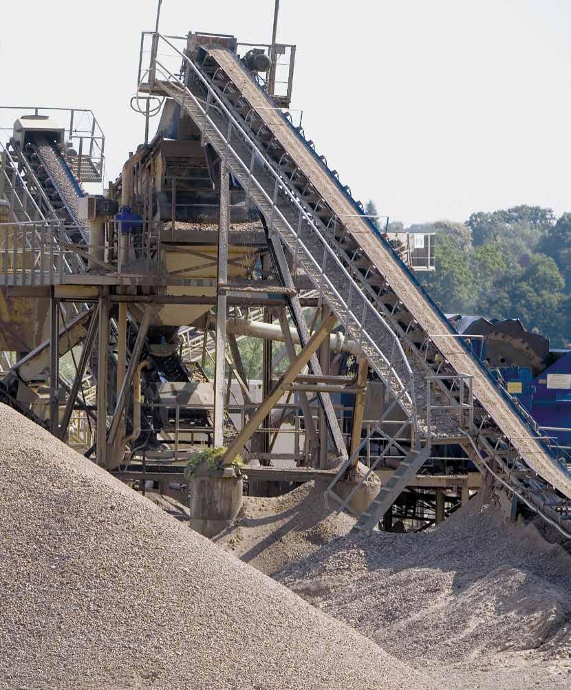
113 113
114 RINGFEDER POWER TRANSMISSION Locking Devices Locking Assemblies Locking Assemblies for bending moments Locking Assemblies Stainless steel Locking Elements Shrink Discs Flange Couplings Damping Technology Friction Springs DEFORM plus DEFORM plus R Special Solutions Locking Assemblies Shaft Couplings 114


115 Partner for Performance Couplings Torsionally Flexible Couplings Torsionally Flexible Couplings Torsionally Flexible Couplings Torsionally Rigid Gear Couplings Torsionally Rigid Barrel Coupling Couplings with variable Stiffness Couplings Metal Bellows Couplings Servo-Insert Couplings Safety Couplings Line Shafts Torsionally Rigid Disc Couplings 115

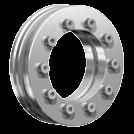

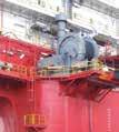


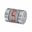

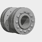


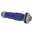


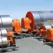


116 RINGFEDER POWER TRANSMISSION GMBH Werner-Heisenberg-Straße 18, D Groß-Umstadt, Germany Phone: +49 (0) Fax: +49 (0) RINGFEDER POWER TRANSMISSION TSCHAN GMBH Zweibrücker Strasse 104, D Neunkirchen, Germany Phone: +49 (0) Fax: +49 (0) RINGFEDER POWER TRANSMISSION USA CORPORATION 165 Carver Avenue, Westwood, NJ 07675, USA Toll Free: Phone: Fax: HENFEL INDÚSTRIA METALÚRGICA LTDA. Av. Major Hilário Tavares Pinheiro, 3447 Cer Jaboticabal - SP - Brazil Phone: Fax: vendas@henfel.com.br RINGFEDER POWER TRANSMISSION INDIA PRIVATE LIMITED Plot No. 4, Door No. 220, Mount - Poonamallee Road, Kattupakkam, Chennai , India Phone: +91 (0) Fax: +91 (0) sales.india@ringfeder.com KUNSHAN RINGFEDER POWER TRANSMISSION COMPANY LIMITED No. 10 Dexin Road, Zhangpu Town , Kunshan, China Phone: +86 (0) Fax: +86 (0) sales.china@ringfeder.com RINGFEDER POWER TRANSMISSION
Locking Assemblies & Locking Elements
 US 12 2010 Locking Assemblies & Locking Elements Partner for performance www.ringfeder.com A Global Presence For You The RINGFEDER POWER TRANSMISSION GMBH was founded in 1922 in Krefeld, Germany to fabricate
Torsionally Rigid Disc Couplings
 US 05 2016 Torsionally Rigid Disc Couplings Partner for Performance www.ringfeder.com Welcome to your system supplier for every aspect of power transmission RINGFEDER POWER TRANSMISSION We say what we
US Nor-Mex. Elastomer Jaw Couplings. Partner for Performance
 US 11 2015 Nor-Mex lastomer Jaw Couplings Partner for Performance www.ringfeder.com Welcome to your system supplier for every aspect of power transmission Today s RINGFDR POWR TRANSMISSION GMBH was founded
Shrink Discs, Smart-Lock & Shaft Couplings
 RINGFEDER Products are available from MARYLAND METRICS Shrink Discs, Smart-Lock & Shaft Couplings US 08 2009 Partner for performance RINGFEDER Products are available from MARYLAND METRICS P.O. Box 261
Power Transmission Solutions
 RINGFEDER Products are available from MARYLAND METRICS Power Transmission Solutions 11 2011 Partners for performance RINGFEDER Products are available from MARYLAND METRICS P.O. Box 261 Owings Mills, MD
Shaft-Hub-Connections
 Stand: 14.01.2010 Shaft-Hub-Connections Shrink Discs Cone Clamping Elements Star Discs 36 Edition 2012/2013 RINGSPANN Eingetragenes Warenzeichen der RINGSPANN GmbH, Bad Homburg Table of Contents Introduction
RINGFEDER Locking Assemblies. Catalogue. RfN For high torques & axial loads
 RINGFEDER Locking Assemblies GB 03 04 Catalogue RfN 7014 For high torques & axial loads RINGFEDER Locking Assemblies RfN 7014 Please note that our guarantee refers to our products only. Because of the
Power Transmission Solutions
 11 2011 Power Transmission Solutions Partner for performance A Global Presence For You The RINGFEDER POWER TRANSMISSION GMBH was founded in 1922 in Krefeld, Germany to fabricate and promote Friction Spring
For advanced drive technology CLAMPEX. Shaft-Hub-Connection. KTR Precision Joints CLAMPEX
 technology CLAMPEX Shaft-Hub-Connection CLAMPEX KTR Precision Joints 07 technology Table of contents Page Brief information 09 Selection and calculation -5 CLAMPEX -Selection Shaft diameter = d 0 10 0
Locking Assemblies Shrink Discs Rigid Couplings.
 M I N I Locking Assemblies Shrink Discs Rigid Couplings www.mav.it our company We are an Italian company world renowned for our creativity and ethics. Established in 1989 we have rapidly built a reputation
NEW. Cone Clamping Elements Trantorque Keyless Locking Devices for very small diameters from 3 mm. E03.050e
 Cone Clamping Elements Trantorque Keyless Locking Devices for very small diameters from 3 mm NEW E03.050e Backlash free positioning Excellent concentricity Quick mounting by central clamping nut Issue
Locking Assemblies for use with bending loads
 EN 03 2011 Locking Assemblies for use with bending loads Partner for performance www.ringfeder.com A Global Presence For You The RINGFEDER POWER TRANSMISSION GMBH was founded in 1922 in Krefeld, Germany
RINGFEDER KEYLESS SHAFT/HUB CONNECTIONS LOCKING ASSEMBLIES TM LOCKING ELEMENTS TM SHRINK DISCS W-300-2
 RINGFEDER KEYLESS SHAFT/HUB CONNECTIONS LOCKING ASSEMBLIES TM LOCKING ELEMENTS TM SHRINK DISCS W-300-2 1 Ringfeder Corporation Catalog W-300-1 Shaft-Hub Locking Devices Ringfeder unique frictional, keyless
RE / STAR Tolerance Rings STAR Ball Knobs, Knob and Lever Type Handles
 RE 2 970/.99 STAR Tolerance Rings STAR Ball Knobs, Knob and Lever Type Handles STAR Tolerance Rings Product Overview Tolerance rings are made of hard, embossed spring steel strip and belong to the class
For advanced drive technology CLAMPEX. Shaft-hub-connection. KTR Precision joints CLAMPEX
 technology CLAMPEX Shaft-hub-connection CLAMPEX KTR Precision joints 227 technology Table of contents Page Brief information 228 Selection and calculation 25-255 CLAMPEX -Selection Shaft diameter = d 0
RFC SPECIALTY LOCKING DEVICES
 RINGFEDER Products are available from MARYLAND METRICS P.O. Box 261 Owings Mills, MD 21117 USA email: sales@mdmetric.com web: http://mdmetric.com phones: (410)358-3130 (800)638-1830 faxes: (410)358-3142
Shaft Couplings Flange-Couplings Rigid Shaft Couplings Flexible Couplings
 Shaft Couplings Flange-Couplings Rigid Shaft Couplings Flexible Couplings 44 Edition 2013/2014 RINGSPANN Registered Trademark of RINGSPANN GmbH, Bad Homburg 2 Table of Contents Flange-Couplings Page Flange-Couplings
RING-flex. Torsionally Rigid Disc Couplings US Partner for performance 1. RINGFEDER Products are available from MARYLAND METRICS
 RINGFEDER Products are available from MARYLAND METRICS RING-flex Torsionally Rigid Disc Couplings US 008 Partner for performance RINGFEDER Products are available from MARYLAND METRICS P.O. Box 6 Owings
In-house development Own manufacturing Sole distributor in Germany Working with distributors worldwide
 In-house development Own manufacturing Sole distributor in Germany Working with distributors worldwide External Clamping devices Overview 3073 Mini-Range For very low torque transmission Very small profile
Shaft Couplings Tru-Line Flange-Couplings Rigid Shaft Couplings Flexible Couplings
 Shaft Couplings Tru-Line Flange-Couplings Rigid Shaft Couplings Flexible Couplings Edition 2015/2016 RINGSPANN Registered Trademark of RINGSPANN GmbH, Bad Homburg Table of Contents Tru-Line Flange-Couplings
Partner for Performance
 Partner for Performance www.ringfeder.com More performance stronger global presence Dear Business Partner, We are pleased to inform you that effective 1st October 2015 the Brazilian company HENFEL (Jaboticabal,
Standard with cone bushing. Backlash-free Safety Clutch
 EAS -Compact ratchetting clutch/synchronous clutch The Backlash-free Safety Clutch for Standard with cone bushing Packaging Machinery Machine Tools Paper Machinery Indexing Drives Servo Motors EAS -NC
Solutions for power transmission. MAV-standardisarja.
 Solutions for power transmission MAV-standardisarja www.konaflex.fi L O C K I N G A S S E M B L I E S Shrink disc Mini Series Rigid Couplings www.mav.it our company We are an Italian company world renowned
RINGFEDER Shrink Discs RfN 4091
 RINGFEDER Shrink Discs RfN 4091 Heavy Duty Series Shrink Disc RINGFEDER RfN 4091 Location Shrink Disc RINGFEDER RfN 4091 Dimensions Lever metric example 40 Size Shrink Disc dimensions Transmissible torques
SIT-LOCK self locking elements
 self locking elements Advantages of on the shaft-hub connection compared with traditional systems Easy assembly and disassembly Both actions take place by locking and unlocking the clamping screws with
Dr. TRETTER AG. Tolerance Rings. safe cost-effective fast assembly
 Dr. TRETTER AG Tolerance Rings safe cost-effective fast assembly Tolerance Rings are corrugated metal strips manufactured of high quality spring steel. Tolerance Rings are a fastening device between two
FRICTIONAL CONNECTIONS CATALOGUE
 FRICTIONAL CONNECTIONS CATALOGUE Reprinting and all other forms of copying, not even partially, is prohibited without permission from Stüwe. Maschinenfabrik GmbH & Co. KG Production: Studio Salewski GmbH,
TRADITIONAL SHAFT HUB CONNECTIONS
 TABLE OF CONTENTS MAV locking devices.... Pg. 2 Traditional shaft hub connections...pg. 3 Advantages of MAV locking devices...pg. 4 The wedge principle..... Pg. 5 Installation removal...pg. 6 Characteristics....
Integral tapered roller bearings Series JK0S
 Integral tapered roller bearings Series JK0S Technical Product Information Features Features FAG integral tapered roller bearings JK0S are ready-to-fit, easily mounted units. The single row bearings are
RINGFEDER Shrink Discs RfN 4073
 RINGFEDER Shrink Discs RfN 4073 Ultra Light Duty Series Shrink Disc RINGFEDER RfN 4073 Location Shrink Disc RINGFEDER Dimensions Worm gear (metric example) 36 Size Shrink Disc dimensions Transmissible
Installation and Operating Instructions for ROBA -ES couplings Type 940. _. _ Sizes 14-48
 Table of contents: Please read and observe this Operating Instruction carefully. A possible malfunction or failure of the clutch and damage may be caused by not observing it. Page 1: - Table of contents
Torque Limiter 320 Series Overview. Torque Limiter 320 Series
 Torque Limiter 0 Series Overview Torque Limiter 0 Series Torque Limiter 0 Series For more than 80 years, Autogard products have led the industry in overload protection with high-quality products, design
Frictional Connections Catalogue
 MMADE IN GERMANY Frictional Connections Catalogue ADE IN GERMANY Certified in accordance with DIN ISO 9001:2008 FRICTIONAL CONNECTIONS TECHNOLOGY THAT CONNECTS Dear business partner, STÜWE GmbH & Co. KG
CLAMPING ELEMENTS SELF-CENTRING RCK 15 TYPE SELF-CENTRING RCK 13 TYPE
 CLAMPING ELEMENTS The clamping system connects one or two component parts solidly to the drive shaft, which allow motion to be transmitted or to withstand an axial thrust. Friction connection enables gaps
Comparison Chart. extremely difficult. Finally, separated components can rarely be re-used.
 JAN 2014 Traditional Connections Why Go Keyless Keyed Bushing Systems Both QD and Taper-Lock bushing and weld-on hub systems are popular component mounting technologies. Yet both are ultimately keyed connections
Slotted nut NMG. Housing nut GWR. Bosch Rexroth AG. for economical constructions. a min. 0,3. M A = tightening torque of slotted nut.
 R310EN 3301 (2009.08) Precision Ball Screw Assemblies Bosch Rexroth AG 113 Slotted nut NMG for economical constructions B D d d1 b M A = tightening torque of slotted nut a min. 0,3 Polyamide insert Designation
Shaft Clamping Elements 8
 Clamping Elements 8 BACK NEXT The Company Cross & orse was established in 14 through the amalgamation of two long standing and well respected companies in the Power Transmission Industry, T.D. Cross and
MULTI CROSS RILLO. Highly flexible tyre coupling with taper bushings
 MULTI CROSS RILLO Highly flexible tyre coupling with taper bushings Maschinenfabrik Dipl.-Ing. Herwarth Reich GmbH Vierhausstr. 53 D-44807 Bochum P.O. Box 10 20 66 D-44720 Bochum Tel.: +49 / (0)234 / 959
Shaft Couplings. Edition 2015/2016. Tru-Line Flange-Couplings Rigid Shaft Couplings Flexible Couplings
 Shaft Couplings Tru-Line Flange-Couplings Rigid Shaft Couplings Flexible Couplings Edition 2015/2016 RINGSPANN Registered Trademark of RINGSPANN GmbH, Bad Homburg 2 Table of Contents Tru-Line Flange-Couplings
RCK CLAMPING ELEMENTS
 RCK CAMPING EEMENTS SERIES RCK 11 page 6 SERIES RCK 13 7 SERIES RCK 15 8 SERIES RCK 16 9 SERIES RCK 19 10 SERIES RCK 40 11 SERIES RCK 45 12 SERIES RCK 50 13 SERIES RCK 55 14 SERIES RCK 60 15 SERIES RCK
Accessories smart additions for efficiency and intelligent performance
 smart additions for efficiency and intelligent performance Metal bellows couplings Perfectionists you can count on Metal bellows couplings are designed for the highest requirements in servo drive technology.
MAXITORQ ELECTRICALLY ACTUATED CLUTCHES AND BRAKES
 MAXITORQ ELECTRICALLY ACTUATED CLUTCHES AND BRAKES HOW TO SELECT THE CORRECT CLUTCH OR BRAKE The easiest way is to ask our application engineers. For clutch application, we need to know: Torque or H.P.
Why Choose Rexnord? 866-REXNORD/ (Within the U.S.) (Outside the U.S.)
 (Outside the U.S.)") 866-REXNORD/866-739-6673 (Within the U.S.) 414-643-2366 (Outside the U.S.) www.rexnord.com Why Choose Rexnord? When it comes to providing highly engineered products that improve productivity and efficiency
866-REXNORD/866-739-6673 (Within the U.S.) 414-643-2366 (Outside the U.S.) www.rexnord.com Why Choose Rexnord? When it comes to providing highly engineered products that improve productivity and efficiency
Flexible Couplings 44
 Flexible Couplings 44 RINGSPANN Registered Trademark of RINGSPANN GmbH, Bad Homburg MTY (81) 83 54 10 18 Why RINGSPANN Flexible Couplings? No connection of shafts without clutches It is a well-known fact
TRANSLATION (OR LINEAR)
") 5) Load Bearing Mechanisms Load bearing mechanisms are the structural backbone of any linear / rotary motion system, and are a critical consideration. This section will introduce most of the more common
5) Load Bearing Mechanisms Load bearing mechanisms are the structural backbone of any linear / rotary motion system, and are a critical consideration. This section will introduce most of the more common
Installation and Operational Instructions for EAS - HTL housed overload clutch Sizes 01 3 Type 490._24.0
 Please read these Operational Instructions carefully and follow them accordingly! Ignoring these Instructions may lead to malfunctions or to clutch failure, resulting in damage to other parts. Contents:
Installation and Operating Instructions for EAS -NC clutch Type 45_. _. _ Sizes 02 and 03
 Table of contents: Please read and observe this Operating Instruction carefully! A possible malfunction or failure of the clutch and any damage may be caused by not observing it. Page 1: - Table of contents
TORQUE LIMITER SERIES 320
 TORQUE IMITER SERIES 320 AUTOGARD SERIES 320 TORQUE IMITER Quality and Autogard are synonymous with overload protection. The company s reputation for high quality products is derived from over 35 years
BEVEL GEAR UNITS ZZ-SERVOLINE
 BEVEL GEAR UNITS ZZ-SERVOLINE ZZ-SERVOLINE GEARBOX DESIGN AND FUNCTIONAL FEATURES Gear Ratios i= 3:1 i= 4:1 i= 5:1 i= 6:1 i= 8:1 i= 10:1 i= 12:1 i= 15:1 Spiral Bevel Gear KLINGELNBERG tooth system Hypoid
Description Symbol Definition or explanation Rated torque T KN Torque that can continuously be transmitted over the entire permissible speed range
 Coupling selection Normally the is selected according to the nominal torque ( ) shown in the list of technical data, like all other coupling systems. In all cases the torque ( ) must exceed the maximum
BoWex FLE-PA. BoWex FLE-PAC. KTR-N Sheet: Edition: EN 1 of BoWex FLE-PA / FLE-PAC Operating/Assembly instructions
 1 of 17 is a torsionally rigid flange coupling. It is able to compensate for shaft misalignment, for example caused by manufacturing inaccuracies, thermal expansion, etc. BoWex FLE-PA BoWex FLE-PAC Drawn:
Selection Tool. on the Internet at in the section MÄDLER -Tools. Other sizes and designs on request. Connecting Shafts Page 766
 Couplings Overview Friction Clutches Friction Clutches Type B Axial Arrangement Friction Clutches Type C Transversal Flexibility Sliding Hubs with Torsionally-Flexible Coupling Multi-Disk Friction Clutches
Bearings and steel balls
 Bearings and steel balls Deep groove ball bearings DIN 625 T1 P. 2-5 Deep groove ball bearings stainless steel DIN 625 T1 P. 2-15 Angular ball bearings DIN 628 T1 P. 2-17 Spindle bearings DIN 628 T1 P.
Backlash-free safety couplings. Backlash-free safety couplings. Product information. Optimal safety has a name: Guaranteed by two systems:
 ;;Engaged ;;Engaged Backlash-free safety couplings Product information Optimal safety has a name: Backlash-free safety couplings Guaranteed by two systems: ;;;; Locking Locking element - cylinder roller
TOOLFLEX Operating-/Assembly Instructions
 D-807 Rheine heet: 5810 EN 1 of 19 Backlash-free, torsionally stiff and maintenance-free coupling is a backlash-free, torsionally stiff and maintenance-free metal bellow-type coupling designed to be used
eline Ball Screw Assemblies
 eline Ball Screw Assemblies R310EN 3314 (2005.06) The Drive & Control Company R310EN 3314 (2005.06) Bosch Rexroth AG 3 Product Overview 4 Technical Data 6 with Screw-in Single Nut ZEV-E-S Single fixed
MAE 322 Machine Design Shafts -3. Dr. Hodge Jenkins Mercer University
 MAE 322 Machine Design Shafts -3 Dr. Hodge Jenkins Mercer University Setscrews Setscrews resist axial and rotational motion They apply a compressive force to create friction The tip of the set screw may
Torsionally elastic couplings
 Torsionally elastic couplings Torsionally elastic couplings Industrial Brakes Thrusters Pressure Oil Pumps Couplings Hydraulic Buffers Cellular Buffers Rail Pliers Sheaves Hook Blocks Crane Rail Wheels
3. BEARING ARRANGEMENT DESIGN
 3. BEARING ARRANGEMENT DESIGN 3.1 GENERAL PRINCIPLES OF ROLLING BEARING ARRANGEMENT DESIGN Rotating shaft or another component arranged in rolling bearings is guided by them in radial as well as in axial
Vibration damping precision couplings
 Vibration damping precision couplings In light of the advantages of elasticity, strength, resilience, and damping effects, elastomer materials are now being used in most areas of mechanical engineering.
Installation and Operational Instructions for EAS -smartic synchronous clutch Type 48_. 5._ Sizes 01 2
 Please read these Operational Instructions carefully and follow them accordingly! Ignoring these Instructions may lead to malfunctions or to clutch failure, resulting in damage to other parts. Contents:
CLAMPEX KTR 100 Operating/Assembly instructions
 1 of 9 The CLAMPEX clamping set is a frictionally engaged, detachable shaft-to-shaft connection for cylindrical shafts and bores without feather key. Table of contents 1 Technical data 2 2 Advice 4 2.1
Installation and Operational Instructions for EAS -Compact overload clutch, Type 49_. 4._ Sizes 4 and 5
 Please read these Operational Instructions carefully and follow them accordingly! Ignoring these Instructions may lead to malfunctions or to clutch failure, resulting in damage to other parts. Contents:
Torsionally Stiff Steel Lamina Couplings. innovative quality products. optimal cost-performance ratio. certified according to DIN ISO 9001
 RGFLEX Torsionally Stiff Steel Lamina Couplings features: innovative quality products large-scale service optimal cost-performance ratio certified according to DN SO 0 worldwide net of distribution www.ktr.com
ROSTA Tensioning Motorbases Type MB. self-adjusting maintenance-free overload-proof non-slip dampen harmful vibrations extend belt drive
 83 Technology ROSTA Tensioning Motorbase Type MB for Belt Drives The ROSTA elastic tensioning motorbase type MB, with the rubber suspension unit as swivel mounting, compensates continuously for all stretching,
RIGIFLEX -N RADEX -N. Steel laminae coupling. Steel laminae coupling. You will find continuously updated data in our online catalogue at
 117 Table of contents 117 Coupling selection steel laminae coupling 119 Description of coupling 121 General information 122 Types and applications 123 Technical data 124 Standard types 126 Special types
Bell-house Mounted Arrangement. Highly Flexible K Coupling
 Bell-house Mounted Arrangement. Highly Flexible K Coupling K Couplings for bell-house mounted arrangements are the only coupling type providing a blind assembly connection. They are specially designed
ROSTA Tensioning Motorbases Type MB. self-adjusting maintenance-free overload-proof non-slip dampen harmful vibrations extend belt drive
 Technology ROSTA Tensioning Type MB for Belt Drives The ROSTA elastic tensioning motorbase type MB, with the rubber suspension unit as swivel mounting, compensates continuously for all stretching, hopping,
CLAMPEX KTR 400 Operating/Assembly instructions
 1 of 10 The CLAMPEX clamping set is a frictionally engaged, detachable shaft-to-shaft connection for cylindrical shafts and bores without feather key. Table of contents 1 Technical data 2 2 Advice 2.1
The perfect connection for a perfect performance. The FLUDEX ARPEX combination for a soft starting torque now comes in a standardized series
 The perfect connection for a perfect performance The FLUDEX ARPEX combination for a soft starting torque now comes in a standardized series siemens.com/hydrodynamiccouplings Answers for industry. Produced
Gerotor pump, fixed displacement volume
 Gerotor pump, fixed displacement volume RE 10545/12.11 1/12 Type GZ Component series 1X Maximum operating pressure 15 bar Maximum displacement 140 cm³ H7572_d Table of contents Contents age eatures 1 Ordering
Compact Modules. with ball screw drive and toothed belt drive R310EN 2602 ( ) The Drive & Control Company
 The Drive & Control Company") with ball screw drive and toothed belt drive R310EN 2602 (2007.02) The Drive & Control Company Bosch Rexroth AG Linear Motion and Assembly Technologies Ball Rail Systems Roller Rail Systems Linear Bushings
with ball screw drive and toothed belt drive R310EN 2602 (2007.02) The Drive & Control Company Bosch Rexroth AG Linear Motion and Assembly Technologies Ball Rail Systems Roller Rail Systems Linear Bushings
Installation and Operational Instructions for ROBA -D Couplings Type 91_. _
 Please read the Installation and Operational Instructions carefully and follow them accordingly! Ignoring these Instructions may lead to malfunctions or to coupling failure, resulting in damage to other
SafeSet Torque-limiting Safety Coupling
 Torque-limiting Safety Coupling Voith Turbo Safeset We are the experts in torque-limiting and connection couplings at Voith Turbo. Voith Turbo, the specialist for hydrodynamic drive, coupling and braking
 heet: 1 of 22 Backlash-free, torsionally stiff and maintenance-free coupling Type with setscrew Type with clamping hubs Type KN (Taper hubs) Type M with setscrew Type M with clamping hubs Type PI 11-3379-883
ZERO-POINT CLAMPING SYSTEM
 simple. gripping. future. ZERO-POINT CLAMPING SYSTEM 22 Quick Point Grid Plates 3 Quick Point Plates 34 Quick Point Round Plates 39 Quick Point Adaptor Plates 4 Quick Point Clamping Studs 43 Quick Point
Installation and Operational Instructions for ROBA -DS couplings Type 95. _ (disk pack HT) Sizes
 Sizes") (B.9.7..ATEX.EN) Please read these Operational Instructions carefully and follow them accordingly! Ignoring these Instructions may lead to malfunctions or to coupling failure, resulting in damage to other
(B.9.7..ATEX.EN) Please read these Operational Instructions carefully and follow them accordingly! Ignoring these Instructions may lead to malfunctions or to coupling failure, resulting in damage to other
TECHNICAL INFORMATION
 General Nomenclature Spherical Roller Bearings The spherical roller bearing is a combination radial and thrust bearing designed for taking misalignment under load When loads are heavy, alignment of housings
Chapter 7. Shafts and Shaft Components
 Chapter 7 Shafts and Shaft Components 2 Chapter Outline Introduction Shaft Materials Shaft Layout Shaft Design for Stress Deflection Considerations Critical Speeds for Shafts Miscellaneous Shaft Components
ROSTA MOTORBASES ROSTA. Self-Tensioning Motor Mount for Belt Drives. without slippage self-adjusting maintenance-free
 MOTORBASES Self-Tensioning Motor Mount for Belt Drives without slippage self-adjusting maintenance-free Technology Tensioning Motorbase Type MB for Belt Drives The elastic tensioning motorbase type MB,
TSCHAN -B. Installation and Operation Manual TSCHAN Flexible Coupling BAWB 001-GBR-0 06/2004
 BAWB 001-GBR-0 06/2004 Installation and Operation Manual TSCHAN Flexible Coupling TSCHAN -B BH TSCHAN GmbH Zweibrücker Straße 104 D-66538 Neunkirchen-Saar Telefon: +49(0) 6821 866 0 Telefax: +49(0) 6821
LOCKING BUSHES & SHAFT COLLARS
 LOCKING BUSHES & SHAFT COLLARS INDEX TAPER BUSHES Page 3 WELD-ON HUBS Page 4 QD BUSHES Page 5 MECHANICAL LOCKING BUSHES CAL1 (Not Self-Centering) Page 6 CAL2 (Not Self-Centering) Page 7 CAL3 (Self-Centering)
PRECISION BELLOWS COUPLINGS
 PRECISION BELLOWS COUPLINGS Bellows couplings are used where precise rotation, high speeds, and dynamic motion must be transmitted. They exhibit zero backlash and a high level of torsional stiffness, offering
Clamping elements and precision joints
 262 and precision joints CLAMPEX Types of clamping elements 264 Selection guide 266 Selection 267 Example of calculation/selection 268 Calculation of hubs and technical data 269 KTR 100 270 KTR 105 272
RADEX -N Composite Operating/Assembly instructions
 1 of 14 RADEX -N is a torsionally stiff flexible steel lamina coupling. It is able to compensate for shaft misalignment, for example caused by thermal expansion, etc. note ISO 101. Drawn: 0.05.15 Kb/Wig
Installation and Operational Instructions for ROBATIC -clutch Type and Type Sizes 3 9
 Please read the Operational Instructions carefully and follow them accordingly! Ignoring these Instructions may lead to malfunctions or to clutch failure, resulting in damage to other parts. Contents:
RINGFEDER POWER TRANSMISSION GMBH Werner-Heisenberg-Straße 18, D Groß-Umstadt, Germany Phone: +49 (0) Fax: +49 (0)
 Fax: +49 (0)") Installation and Operation Manual Flexible Coupling Installation and Operation Manual TSCHAN Flexible Coupling TSCHAN -B BH BAWB 001 -GBR-1 03/2010 RINGFEDER POWER TRANSMISSION GMBH Werner-Heisenberg-Straße
Installation and Operation Manual Flexible Coupling Installation and Operation Manual TSCHAN Flexible Coupling TSCHAN -B BH BAWB 001 -GBR-1 03/2010 RINGFEDER POWER TRANSMISSION GMBH Werner-Heisenberg-Straße
TORQLIGHT SAFETY COUPLINGS
 LIGHTWEIGHT AND COMPACT single-position TOQLIGHT SAFETY COUPLINGS SEIES SL 10 700 Nm THE ULTIMATE COUPLING FOM 10 700 Nm SEIES SL DESIGN / FEATUES Extremely lightweight construction Up to 60 % weight reduction
Why Choose Rexnord? 866-REXNORD/ (Within the U.S.) (Outside the U.S.)
 (Outside the U.S.)") 866-REXNORD/866-739-6673 (Within the U.S.) 44-643-366 (Outside the U.S.) www.rexnord.com Why Choose Rexnord? When it comes to providing highly engineered products that improve productivity and efficiency
866-REXNORD/866-739-6673 (Within the U.S.) 44-643-366 (Outside the U.S.) www.rexnord.com Why Choose Rexnord? When it comes to providing highly engineered products that improve productivity and efficiency
Rotary-Linear Actuator HSE4 Hydraulic / 100 Bar
 Rotary-Linear Actuator HSE4 Hydraulic / 100 Bar 4 Function and features K A1 G1 B1 G2 KM Y B2 RE A2 Z S2 A S1 W B KS [ Operation ] [ Operating pressure ] The Eckart rotary-linear actuator HSE4 is a combination
SCHMIDT-KUPPLUNG GmbH
 Loewe GK About us Many years of experience For 50 years, we have been advising machine manufacturers as partners for compact coupling systems. Our experience in power transmission has given us extensive
LIGHTWEIGHT AND COMPACT. SERIES SL Nm. single-position multi-position. THE ultimate COUPLING from Nm
 LIGHTWEIGHT AND COMPACT L SAFETY COUPLINGS TOQLIGHT SEIES SL 5 700 Nm THE ultimate COUPLING from 5 700 Nm SEIES SL DESIGN / FEATUES Extremely lightweight construction Up to 60 % weight reduction in comparison
POSI-LOCK. Connects the Shaft and Hub with the Wedging Action of the Tapered Surface. Mechanical Shaft Lock ETP BUSHINGS
 Mechanical Shaft ock POSI-OCK Mechanical Shaft ock POSI-OCK Application Machine tool, pump, molding machine, printing machine, palletizing robot, various jigs and tools Connects the Shaft and Hub with
FLEXIBLE COUPLINGS - RIGID COUPLINGS Up to Nm of torque and 205 mm bores
 Edition 10/2014 www.comintec.it FLEXIBLE COUPLINGS - RIGID COUPLINGS Up to 130.000 Nm of torque and 205 mm bores (BACKLASH FREE) Technology for Safety FLEXIBLE COUPLINGS - RIGID COUPLINGS (BACKLASH FREE):
Axial-radial cylindrical roller bearings
 Axial-radial cylindrical roller bearings Designs and variants.............. 320 Bearing data..................... 321 (Boundary dimensions, tolerances) Product table 5.1 Axial-radial cylindrical roller
KTR Torque Limiters Overload Protection Systems
 KT Torque Limiters Overload Protection Systems UFLEX - Friction Disk - Zero Backlash Ball Detent KT SI - Ball/oller Bearing Style KT SI Compact - Zero Backlash Ball Detent Catalog Contents (Metric) Page
Online data sheet. DBS60E-S4EP05000 DBS60 Core INCREMENTAL ENCODERS
 Online data sheet DBS60ES4EP05000 DBS60 Core DBS60ES4EP05000 DBS60 Core A B C D E F Ordering information Type Part no. DBS60ES4EP05000 1071649 Other models and accessories www.sick.com/dbs60_core Illustration
TORQUE LIMITER SERIES 600. Airjustor
 TORQUE LIMITER SERIES 600 Airjustor Quality and Autogard are synonymous with overload protection. The Company's reputation for high quality products is derived from over 40 years of design, innovation
Please read these Operational Instructions carefully and follow them accordingly!
 Sizes 3 to 5 Please read these Operational Instructions carefully and follow them accordingly! Ignoring these Instructions may lead to malfunctions or to coupling failure, resulting in damage to other
The right twist for your machine. Torque motors 1FW6
 The right twist for your machine Torque motors 1FW6 Achieve higher dynamics and precision smoothly In the machine tool industry and other sectors, there is a constant demand for greater precision and higher