Electronic Ballast EVG 2000-T
|
|
|
- Ursula Anthony
- 5 years ago
- Views:
Transcription


1 Electronic Ballast EVG 2000-T Operating Manual
2 Table of contents 1 Description 1.1 Advantages of this ballast Functional principle Energization Visualization Indications and signalling Switch-on behaviour in case of Cooling Safety requirements when using the unit together with ultraviolet lamps Repairs Technical data 2.1 Mains connection Lamp connection Connection plug arrangements Page 2 technical changes reserve
3 1 Description 1.1 Advantages of this ballast Lamp power can be adjusted steplessly Lamp power can be automatically controlled to a constant value set Different lamps can be connected to the same ballast It is possible to operate nearly all types of mercury vapour medium-pressure lamps and metal halide lamps (doped mercury vapour lamps) the electrical characteristics of which are in the wide operating range of unit Lamp power can be pulsed quickly All functions are controlled via galvanically separate analogue inputs DC V or ma Any voltage variations are compensated Easy to install by little wiring work Smaller and lighter than a comparable conventional ballast Air cooling Advanced technology with digital control The ballast meets the requirements of DIN EN / VDE 0160 and other European and global standards (IEC). 1.2 Functional principle The EVG 2000-T unit is an electronic, controllable AC ballast for lamps of a nominal power from 500 W to 2000 W which is intended to be used for industrial applications. The unit is designed for the operation with lamps. The lamps are operated by a square-wave current, and thus the dark phase in the current s zero passage as usual in conventional ballasts. The EVG 2000-T unit s function is based on a controllable power source up to 14 A. During the operation the lamp power is controlled and kept constant at an external set value via an internal control unit. The lamp s nominal voltage may be between approx. 100 V and 300 V. However, in order to get the full power of 2000 W, the maximum current of 14 A should be considered so that a minimum lamp voltage of 145 V is necessary. In most lamps the power can be adjusted from approx. 10 to 100 %, depending on the cooling and ambient conditions. Using the integral power control unit, the lamp power is set from the outside via an analogue input (DC V or ma). Doing so, the minimum and maximum values as necessary and allowable for each lamp must be taken into account. This control unit is used to control the set point to a constant value, i.e. to keep the lamp power constant, irrespective e.g. of the voltage or different lamp voltages. The EVG 2000-T unit has a galvanic separation between the main and control circuit and can be controlled directly, e.g. by a stored-program control (SPS), via DC V/ ma input. If DC < 1V at the input, the lamp is switched off (no safe disconnection as required by VDE because here semiconductors are used to switch! For this reason, a main switch or a relevant contactor is necessary in case of servicing work, e.g. for replacing the lamp). By de, the unit is equipped in the factory with an internal, temperature-controlled ventilator (keep in mind that the maximum cooling air temperature is 40 C!). The cooling air may not be contaminated or exert any other negative influence on the electronics (e.g. by aggressive gases or high humidity). The EVG 2000-T ballast can be used as a tabletop unit or installed in a switch cabinet etc. General note for electric measurements! For measurements around the ballast, e.g. to measure the and lamp currents or voltages, a true RMS measuring instrument with a frequency range of up to at least 10 khz is necessary. In most cases, other instruments do not indicate the correct values, in particular, the lamp current and voltage. When measuring the lamp voltage, be aware of the fact that ignition pulses may destruct the measuring instrument Page 3 technical changes reserve

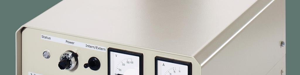
4 1.3 Energization Potentiometer for Powercontrol (For using the Potentiometer pin 2 and 7 from connection 1 bridged) Switch for Operation Mode intern / extern Status-LED refer to Chapter 1.5 Amperemeter Lamp Voltage Connection 2 refer to Chapter 2.3 Connection 1 refer to Chapter 2.3 Voltmeter Lamp Voltage RS232 refer to Chapter 1.4 Cooling air ventilator Air inlet Note: The inputs and outputs have a delay of 3 s from switching ON the, in order to avoid an uncontrolled behaviour during the internal run-up. Analogue power control input: (use a shielded cable!) Signals of EVG 2000-T : Potentiometer (R > 2k) or DC V (Ri < 10k) and DC ma (has priority to DC V input) DC < 0.9V = OFF DC > 1V = ON and igniting DC V = ON; lamp power % or 4 20 ma (Ri = 250 ) ma = OFF ma = ON; lamp power % within the current limits ~ A Multicolour LED (green, orange, red) to signal the status Potential-free change-over contact to signal a trouble 2 outputs for external LEDs : 1 output indicates OK by a green LED to be provided by the customer 1 output indicates FAULT by a red LED to be provided by the customer A 220 Ohm resistor is integrated in EVG 2000-T for each output. The typical LED current is 10mA each. RS232 interface: Integrated (refer to 1.4) Note: Reset: In case of, do not immediately disconnect the EVG 2000-T from the because, otherwise, the reason of is not issued. is possible by disconnecting from for at least 10 s (e.g. after a message) Page 4 technical changes reserve

5 1.4 Visualization Optionally, the ballast is delivered with a serial interface and visualization software. The visualization system shows all s found in the EVG 2000 ballast as well as the internal measuring values. The maximum output power is parameterized via the software, too. Parameters and data in the ballast Parameter input Maximum power Maximum output power Setpoint Output power Send data Output voltage Output current Fault bit Intermediate circuit voltage Start Intermediate circuit current Short circuit Temperature / PFC Line-to-earth Temperature / PWM Mains undervoltage Mains voltage Overtemperature Status Ventilator ON Intermediate circuit overvoltage Start-up Intermediate circuit undervoltage Maximum power Intermediate circuit overcurrent Operating: Sio-Start Sio-Stop Sio-Status Versions EVG Send Data Exit Communication is started; RS232 interface is configured by the visualization software. Communication is stopped; RS232 interface is released for other programs Red: Communication not started or stopped Yellow: Communication erroneous Green: Communication OK Firmware version is read out The value adjusted in the field Maximum output power is transmitted to the ballast. Program is ended Page 5 technical changes reserve
6 1.5 Indications and signalling On the casing of the EVG 2000-T ballast there is a three-colour light-emitting diode to signalize different states. In addition, a potential-free change-over contact is available to identify any troubles. Some interconnections are shown in the table below: Operating mode Normal Warning Fault LED Diagnosis Status Signalling contact Remark LED green, lights permanently LED green, long LED orange, lights permanently LED orange, short LED red/orange, short LED red/orange, long LED red, long LED red, short LED red, lights permanently Energization voltage 1.0V Energization voltage < 0.9V Energization voltage 1.0V Risk of overtemperature (heat sink temperature >70 C, reset at <65 C) Mains voltage <190 V (but not 0 V) Overtemperature (heat sink temperature >80 C, reset at <75 C) Output circuit is open or the lamp does not ignite Short circuit in the output circuit Line-to-earth in the output circuit Desired power is reached (depending on the energization voltage) Ballast is ready for switching ON Lamp voltage is too low, desired power is not reached, no load (10 s) Unit re in switched ON state OFF, OFF, OFF, no lamp is connected or the lamp does not ignite OFF OFF Relay has released, no Relay has released, no Relay has released, no Relay has released, no Storing, reset is possible by Storing, reset is possible by Wait for three ignition attempts. Storing. Reset is possible by Storing, reset is possible by ( Short circuit may also be induced if the lamp s start voltage is too low, <10V for 10s) Storing, reset is possible by Flashing frequencies: Long = 1s ON, 1s OFF (0.5 Hz); short = 2x per second ON (2 Hz) Page 6 technical changes reserve
7 1.6 Switch-on behaviour in case of The lamp does not ignite or is not connected: The EVG 2000-T ballast attempts for 10 s to ignite the lamp (LED orange, lights permanently; potential-free changeover contact has pulled up). If the lamp does not ignite within this time, a break of 30 seconds will follow. During this break the LED is flashing red with a low frequency and the potential-free change-over contact has pulled up. After the first ignition attempt was not successful, a second ignition attempt and, if necessary, a third ignition attempt is made in the above-described manner. After the third ignition attempt the unit will remain in the status and the red LED is long. In order to be able to start a fourth and further ignition attempts, it is necessary to disconnect the unit from the power supply and then to switch ON again. 1.7 Cooling In order to guarantee the maximum power output and life of the EVG 2000-T ballast, it is important to efficiently cool the unit. The cooling effect depends on the air volume flowing through the heat sink and the air temperature. To reach the full power output of up to 2000 W, the air temperature may not be higher than 40 C. Pay attention to this fact, in particular, when the unit is installed in a switch cabinet or a similar casing. Arrangements should be made to ensure that the lost heat of the unit can be sufficiently dissipated! The EVG 2000-T ballast is equipped with a temperature-controlled ventilator and is independently switched ON or OFF if a defined heat sink temperature is reached. Note for controlling the ventilator! If the ballast is disconnected from the, the ventilator continues to run for approx. 10 s and, doing so, it discharges the intermediate circuit capacitors. 1.8 Safety requirements when using the unit together with ultraviolet lamps Before starting any work at the connections of the ballast or UV lamp, e.g. when replacing the lamp, it is necessary to completely disconnect the unit from the by actuating the main contactor or main switch, to preclude the risk of an electrical shock. After having switched OFF the unit, wait still for 10 minutes to ensure that the capacitors can be discharged to a nonhazardous value. Reason: According to the operation principle, the ultraviolet lamp is switched OFF by semiconductors. However, this does not involve a safe the as required by VDE! There is the risk of residual voltages!! Danger to life! 1.9 Repairs The EVG 2000-T ballast is a reliable electronic unit which, according to experience gained hitherto, may be hardly damaged. If, contrary to expectations, this should be happen the unit may be repaired by replacing the defective parts and subsequent detailed performance test at the factory Page 7 technical changes reserve
8 2 Technical data Electrical data of the trouble signalling contact: Protection against short circuit and overload in the lamp circuit: Protection against line-to-earth in the lamp circuit: Nominal voltages AC 250 V / DC 30 V Maximum continuous current 16 A Maximum switching capacity (AC) 500W / 750VA Maximum switching current (AC with 230V) Maximum switching current (DC with 30 V) Minimum switching load 300 mw, 5 V, 5 ma yes yes 30 A 16 A Efficiency: > 91% Ambient temperature: 5 C to 50 C Mounting position: Longitudinal axis in horizontal position Dimensions: 263 x 173 x 340 mm (w x h x d) Weight: 8.5 kg 2.1 Mains connection Mains voltage and frequency: Connection: Power factor: 196 to 255V at 50 and 60Hz L1, N and PE > (with full load) THDi : < 3.0% Fuse /: - Protective motor switch (tripping current Ia is calculated as follows) Ia = PS * 1.15/ UNetz wherein PS = maximum lamp power desired, in W Unetz = actual minimum voltage - B 16 automatic circuit breaker Peak value of starting current when is switched ON: Typically approx. 35A (10ms) Peak value of starting current when the lamp is switched ON: No EMC: DIN EN 55011/VDE 0875 Part 11, class A, group 1 When used in residential areas (class B, group 1), an additional external line filter is necessary. Fault-current circuit breaker: When -current circuit breakers are used, the units shall have a DC tripping system. Main switch or protective motor switch A contactor is necessary to safely disconnect the unit from as specified by IEC and VDE regulations, in order to avoid any residual voltages at the lamp connection. Instead of the contactor, the disconnecting function can also be implemented by a main switch or a suitable protective switch. 2.2 Lamp connection Output frequency: Maximum lamp current: Lamp voltage: No-load voltage: 55 Hz, square wave 14.4 A 100 V to 300 V 420 V Page 8 technical changes reserve
 for doped lamps 3 m For reasons of electromagnetic compatibility, the")
9 Maximum lamp power: 2000 W (with lamp voltages > 145 V) Pulse operation: Rise time / lamp current 50 ms Fall time / lamp current 50 ms Maximum cable length between EVG 2000-T and ignitor: 30 m Maximum cable lengths between the ignitor and lamp: for Hg lamps 5 m (these values depend on the cable and lamp types used) for doped lamps 3 m For reasons of electromagnetic compatibility, the cables/lines to the lamp shall be of shielded type. The shield may be earthed on one (!) side only, preferably on the side of the ballast, and led from both lines and the EVG 2000-T unit to a common point! IMPORTANT!! The ignitor is integrated and is switched OFF after 10s!! IMPORTANT!! The cable capacitance between the EVG and lamp may not exceed 1nF (measured from pole to shield). Otherwise, the EVG 2000-T unit will switch OFF itself by sending a line-to-earth message!! 2.3 Connection plug arrangements Connection plug, 10-pole 1 GND 2 Analogue input for power adjustment DC 0V..10V 3 10V output for potentiometer f. power adjustment (10k, max. 8mA) 4 Analogue input for power adjustment DC 4mA..20mA (priority to pin 2) 5 Analogue output DC10V, proportional to the lamp power (10V = 2000W) 6 Reserve 7 GND 8 Anode for external LED green, 10mA, ballast in the EVG unit 9 Anode for external LED red, 10mA, ballast in the EVG unit 10 Maximum power specification, L-aktiv (priority to analogue inputs for desired values) Connection plug, 3-pole 1 Relay contact / NC contact 2 Relay contact / Root 3 Relay contact / NO contact (Relay is pulled up in the status) Use shielded cables! The shield shall be earthed on one side only, together with the ballast, to one common point near the EVG unit! Lamp connection Maximum cable length between the lamp and ignitor: 5m WARNING: When doing any work on the lamp connections, always disconnect the ballast from the! Residual voltages possible! Page 9 technical changes reserve
World Class Power Solutions. Rectifiers. For Stationary Battery Systems in Nuclear Power Plants
 World Class Power Solutions Rectifiers For Stationary Battery Systems in Nuclear Power Plants General 2 1.1 Application Electronically controlled rectifier assemblies are used in conjunction with suitable
Burden Fuse Rating Resistor SAF / SAK6 1NM 10mm M8 12NM SAF / SAK10 2NM 16mm M8 12NM
 Contents Section Page 1.0 Introduction 1 2.0 Specification 1-4 3.0 Installation 5-8 4.0 Programming 9-10 5.0 Menus 10-12 6.0 Fault Finding/Diagnostics 12-13 7.0 Communication 13 8.0 Setting Up 13-16 1.0
LED Driver Linear / area dimming industry. Driver LC 150W mA IND sl EXC EXCITE series
 Driver LC 150W 200 1050mA IND sl EXC EXCITE series Product description Constant current built-in Driver for LED, particularly suitable for industrial applications in tough environments such as cold warehouses
Other Devices. Installation Contactors Z-SCH. Connection diagrams Z-SCH NO 3 NO / 1 NC. Permitted Installation Positions
 Installation Contactors Z-SCH These switching devices have been designed and rated particularly for modular installation in modular distribution boxes for electrical installation or cabinets with device
Model Number Structure
 Solid State Relays (Single-phase) G3PB New Single-phase Solid State Relays with Compact Size for Heater Control Slim models with a thickness of only 22.5 mm are also available. Compact design achieved
& HIGH CURRENT DC POWER SUPPLIES INSTRUCTION MANUAL
 72-6850 & 72-6852 HIGH CURRENT DC POWER SUPPLIES INSTRUCTION MANUAL Table of Contents Introduction 2 Specification 2 Safety 4 EMC 5 Installation 6 Connections 6 Operation 7 Maintenance and Repair 8 www.tenma.com
MAKING MODERN LIVING POSSIBLE. Quick Setup VLT FCM 300 Series. Phone: Fax: Web: -
 MAKING MODERN LIVING POSSIBLE Quick Setup VLT FCM 300 Series Factory setting Motors type B14 & B34 mounting Reset (pushbutton) Start Jog Speed reference Fig. 1 - Reset to be closed short time for resetting
HGM1780. Automatic Genset Controller USER MANUAL. Smartgen Technology
 HGM1780 Automatic Genset Controller USER MANUAL Smartgen Technology Smartgen Technology Co., Ltd No. 28 Jinsuo Road Zhengzhou Henan Province P. R. China Tel: 0086-371-67988888/67981888 0086-371-67991553/67992951
Products Tde Macno. User s Manual BRAKING UNIT. Cod. MP00401E00 V_1.0
 Products Tde Macno User s Manual BRAKING UNIT Cod. MP00401E00 V_1.0 SUMMARY 1 GENERAL DESCRIPTION... 2 2 USE LIMITATIONS... 2 2.1 Climatic Class... 2 2.2 Resistance To Chemically Active Substances...
Installation and Maintenance Instructions. World Leader in Modular Torque Limiters. PTM-4 Load Monitor
 World Leader in Modular Torque Limiters Installation and Maintenance Instructions PTM-4 Load Monitor 1304 Twin Oaks Street Wichita Falls, Texas 76302 (940) 723-7800 Fax: (940) 723-7888 E-mail: sales@brunelcorp.com
(with Class-1 AC resistive load) 3. G3PB-215B-2N-VD kW max. (25 A) G3PB-225B-3N-VD 2. G3PB-225B-2N-VD kw max. (35 A) G3PB-235B-3N-VD 2
 3. G3PB-215B-2N-VD kW max. (25 A) G3PB-225B-3N-VD 2. G3PB-225B-2N-VD kw max. (35 A) G3PB-235B-3N-VD 2") Solid-state Contactor (New Heat Sink Construction) G3PB Space and working time saved with new heat sink construction. Series now includes 480-VAC models to allow use in a greater range of applications.
Solid-state Contactor (New Heat Sink Construction) G3PB Space and working time saved with new heat sink construction. Series now includes 480-VAC models to allow use in a greater range of applications.
SINAMICS GM150 IGCT version
 /2 Overview /2 Benefits /2 Design /6 Function /8 Selection and ordering data /8 Options Technical data /14 General technical data /15 Control properties /15 Ambient conditions /16 Installation conditions
RVS-AX Instruction Manual
 RVS-AX Analog Soft Starter 8-170A, 220-600V Instruction Manual Ver. 10/11/2009 2 Table of Content RVS-AX Instruction Manual 1. TABLE OF CONTENT 1. Table of Content...2 2. Safety & Warnings...3 2.1 Safety...3
HIGH POWER SOLENOID DRIVER 1
 Elactis SA Switzerland Phone : Fax : E-mail : Web : +41 22 364 65 85 +41 22 364 65 87 info@elactis.com http://www.elactis.com HIGH POWER SOLENOID DRIVER 1 ADRV1012K 1 This datasheet is a preliminary description.
ATOTH-G Series BLDC Motor Controller. User s Manual
 ATOTH-G Series BLDC Motor Controller User s Manual Contents Chapter One Summary...1 Chapter Two Main Features and Specifications.2 2.1 Basic Functions...2 2.2 Features... 5 2.3 Specifications...6 Chapter
Special voltages: Voltage >500 V AC are only permissible with external control box. 3-phase AC Voltages/frequencies. 1-phase AC Voltages/frequencies
 General information Actuator controls AC 01.2 for controlling multi-turn actuators of the SA/SAR type range and part-turn actuators of the SQ/SQR.2 type range. Power supply Standard voltages AC: 3-phase
TECHNICAL DATA SHEET KVA UPS Systemss
 Återförsäljare: Tre Röda AB TillingeHagby 7-745 94 ENKÖPING Tel: 08-560 200 22 e-post: info@treroda.nu http: www.treroda.nu When the INSIDE is important make the OUTSIDE Cannon TECHNICAL DATA SHEET 400-500-600-800
Devices Supported: KEB48220 KEB48221 KEB48300 KEB48301 KEB48400 KEB48401 KEB48600 KEB48601 KEB72330 EB KEB72450 KEB EB KEB72600 KEB
 Kelly KEB Brushless Motor Controller User s Manual Devices Supported: KEB48220 KEB48221 KEB48300 KEB48301 KEB48400 KEB48401 KEB48600 KEB48601 KEB72330 KEB EB72 72331 KEB72450 KEB EB72 72451 KEB72600 KEB
ABB i-bus EIB EIB Power Supply Units SV/S SV/S SU/S
 Product Manual ABB i-bus EIB EIB Power Supply Units SV/S 30.320.5 SV/S 30.640.5 SU/S 30.640. Intelligent Installation Systems Contents Page EIB Power Supply Units. Introduction.........................................
Varispeed E7. Varispeed E7. Varispeed. Varispeed E7. Varispeed E7. Varispeed E7 INVERTER SERIES
 INVERTER SERIES Varispeed E VARISPEED E YASKAWA INVERTER DRIVE TECHNOLOGY Contents Content Page 2 Experience & Innovation A leader in Drives technology Page 3 Specifications Experience & Innovation For
Technical Data Sheets
 GE Consumer & Industrial Power Protection Technical Data Sheets Digital Energy Uninterruptible Power Supply SitePro 150 200 250 300 kva 400 VAC CE Series 6 Manufactured by: GE Digital Energy General Electric
EPS/ELA-Series User Manual EPS/ELA 250W
 EPS/ELA-Series User Manual EPS/ELA 250W EPS Stromversorgung GmbH Tel: +49 (0)821 570451 0 Index 3 Page: 1 Table of contents: Page 1. Features of ELA-Series... 3 1.1 Basic Functions... 3 1.2 Options...
Essential equipment for all your requirements
 NEW CTX CONTACTORS Essential equipment for all your requirements 9 A TO 310 A THREE-POLE INDUSTRIAL CONTACTORS CTX three-pole industrial contactors, a sense of family The new range of CTX contactors provides
MODULAR DEVICES. 21. Isolator Switches. Low Voltage (Bell) Transformers. Time Switches (electromechanical)
 Transformers. Time Switches (electromechanical)") MODULAR DEVICES The range of two, three and four pole isolator switches are of a modular design and fit on DIN 50022 rail. Terminal capacity is 25mm 2. Isolator Switches Rating Poles Modules Reference
MODULAR DEVICES The range of two, three and four pole isolator switches are of a modular design and fit on DIN 50022 rail. Terminal capacity is 25mm 2. Isolator Switches Rating Poles Modules Reference
QS20.241, QS C1
 QS2.21, QS2.21C1 QSeries 27. APPLICATION NOTES 27.1. REPETITIVE PULSE LOADING Typically, a load current is not constant. It varies over time. For pulse load compatibility, following rules must be met:
Commissioning Instructions Inbetriebnahme Anleitung VB 230/ L (LP)
") Commissioning Instructions Inbetriebnahme Anleitung VB 230/400-25 L (LP) Quality is our Drive. Qualität ist unser Antrieb. VB230/400-25L (LP) 1 as per 03/06 1B000.10001 Table of Contents Page 1. Safety
Commissioning Instructions Inbetriebnahme Anleitung VB 230/400-25 L (LP) Quality is our Drive. Qualität ist unser Antrieb. VB230/400-25L (LP) 1 as per 03/06 1B000.10001 Table of Contents Page 1. Safety
Technical Data Sheets
 GE Consumer & Industrial Power Protection Technical Data Sheets Digital Energy Uninterruptible Power Supply SitePro 400 & 500 kva 400 VAC CE Series 6 Manufactured by: GE Digital Energy General Electric
UV- TECHNOLOGY. Technical Documentation ELC N6 / ELC N8 / ELC N10
 our name is our principle UV- TECHNOLOGY Technical Documentation ELC N6 / ELC N8 / ELC N10 GB eta plus electronic gmbh Lauterstraße 29, D-72622 Nürtingen, Telefon +49 (0) 70 22-60 02-80, Fax +49 (0) 70
MB A 12V/24V DC PROGRAMMABLE DUAL BATTERY ISOLATOR
 MB-3688 120A 12V/24V DC PROGRAMMABLE DUAL BATTERY ISOLATOR User Manual Warning and Precautions MB-3688 is built with corrosion resistant material and the main electronic assembly is well sealed inside
DEVICE STATE/BYPASSED FAILURE OVERLOAD
 Technical specifications Type 5. 7. Control electronics Rated values Terminal Rated control supply voltage A1A2 V AC 115 230 115 230 Tolerance % -15+10-15+10 Rated control supply STANDBY ma 15 15 Rated
Phoenix Inverter
 Manual EN Handleiding NL Manuel FR Anleitung DE Manual ES Appendix Phoenix Inverter 12 250 12 375 12 500 12 800 24 250 24 375 24 500 24 800 48 250 48 375 48 500 48 800 1. Safety instructions WARNING: ELECTRIC
Power Electronics. POWERSWITCH Semiconductor Relay / - Contactor With Load Circuit Monitoring PH 9270
 Power Electronics POWERSWITCH Semiconductor Relay / - Contactor With Load Circuit Monitoring PH 9270 0255163 Semiconductor relay PH 9270.91 Semiconductor contactor PH 9270.91/000/02 AC semiconductor relay
1 potential-free change-over contact (max. 24 V DC/1 A) for SIL collective failure signal SIL functions - safety functions Standard: Safe ESD
 for SIL collective failure signal SIL functions - safety functions Standard: Safe ESD") General information AC 01.2 Actuator controls in SIL version for controlling multi-turn actuators of the SA/SAR.2 type range and part-turn actuators of the SQ/SQR.2 type range. Information on SIL features
General information AC 01.2 Actuator controls in SIL version for controlling multi-turn actuators of the SA/SAR.2 type range and part-turn actuators of the SQ/SQR.2 type range. Information on SIL features
Technical Data Sheets
 GE Consumer & Industrial Technical Data Sheets Digital Energy Uninterruptible Power Supply SG-CE Series 160 200 250 300 kva PurePulse TM 400 Vac CE Series 1 Date of issue: 15.02.2007 SGSE160-200S1UPS01
SPECIFICATIONS UPS Triple Output 13.6VDC/213W, 48VDC/153W, 48VDC/39W
 Page 1 / 7 Full operation without need of battery Two independent 48Vdc outputs for switching and control Local monitoring with 8 LEDs Remote monitoring with 4 alarm relays Monitoring and configuration
ABB i-bus KNX Room Master, MDRC RM/S 4.1, 2CDG R0011
 2CDC 071 020 S0012 The Room Master is a modular installation device (MDRC) in Pro M design. It is intended for installation in the distribution board on 35 mm mounting rails. The assignment of the physical
Operating Instructions. Angle Seat Control Valve. Type 7020
 Operating Instructions Angle Seat Control Valve Type 7020 With: Digital Positioner Type 8048 Electro-pneumatic Positioner Type 8047 Pneumatic Positioner Type 8047 Version: 02/2006 Manual-7020e.doc Art.-No:
.3 Section Waste Management and Disposal.
 Issued 2005/06/01 Section 16261 Uninterruptible Power Systems Static Page 1 of 10 PART 1 GENERAL 1.1 RELATED SECTIONS.1 Section 01330 Submittal Procedures..2 Section 01780 Closeout Submittals..3 Section
INDUCTIVE CONDUCTIVITY SENSOR. Instruction Manual. Bürkert 2001 Subject to technical change without notice
 INDUCTIVE CONDUCTIVITY SENSOR Instruction Manual Bürkert 00 Subject to technical change without notice INTRODUCTION Table of Contents. INTRODUCTION.... Symbols used.... General safety instructions....
SPEEDRIVE INSTRUCTIONS MANUAL
 EN SPEEDRIVE INSTRUCTIONS MANUAL Safety warning. The following symbols shown beside a paragraph represent danger warnings associated to the failure to comply with the corresponding instructions. DANGER!
SINAMICS SM150. 4/2 Overview. 4/2 Benefits. 4/2 Design. 4/6 Function. 4/8 Selection and ordering data. 4/8 Options
 /2 Overview /2 Benefits /2 Design /6 Function /8 Selection and ordering data /8 Options Technical data /1 General technical data /15 Control properties /15 Ambient conditions /16 Installation conditions
SB 2000 PUSH TO SEARCH NEXT STAG E. Aerotech, Inc. FORM: QM 1320
 Inlet Controller SB 2000 USER'S MANUAL AUTO OPEN MANUAL PUSH TO SEARCH NEXT STAG E CLOSE Aerotech, Inc. FORM: QM 1320 4215 Legion Dr. Mason, MI 48854-1036 USA Rev. 3, Sept. 1997 Ph. (517) 676-7070 Fax
RT2DB Excitation and voltage regulation system for synchronous generators
 s RT2DB Excitation and voltage regulation system for synchronous generators Fully digital. Parameter settings done by software. Self monitoring routines. Maintenance free. High reliability. Excellent dynamic
LED Driver Linear / area fixed output industry. Driver LCI 65W 150mA 400mA TOP INDUSTRY sl TOP series
 Driver LCI 65W 150mA 400mA TOP INDUSTRY sl TOP series Product description Fixed output constant current built-in LED Driver, particularly suitable for industrial applications in tough enviromments such
Operating instructions EWB 200
 Operating instructions EWB 200 www.bron-kobold.com 1 Operating instructions EWB 200 Before use Please read all the information contained in these operating instructions carefully. They contain important
Components for EEx e Panels
 Circuit Interrupters / Motor Switches 8006/3 8543/1 8543/2 8548/2 40 A 63 A 80 A 1 160 A 500 V 660 V 500 V 01766E00 No. of poles 12 poles Isolator features Switching capacity 400 V, AC3 11 kw 22 kw 37
Frame size R2, IP20 / NEMA 1
 Dimension drawings 395 Frame size R2, IP20 / NEMA 1 1) 1) Extension modules add 26 mm (1.02 in) to the depth measure. 3AUA0000067783-A Frame size R2, IP20 / NEMA 1 396 Dimension drawings Frame size R3,
LED Driver Linear / area fixed output industry. Driver LCI 100W 350mA 900mA TOP INDUSTRY sl TOP series
 Driver LCI 100W 350mA 900mA TOP INDUSTRY sl TOP series Product description Fixed output constant current built-in LED Driver, particularly suitable for industrial applications in tough enviromments such
Operating manual UPS - System
 Operating manual UPS - System POWERMASTER M MIL 1000VA 7Min. BAX 3330 E UPS-Division Issued 15. August 2006 JOVYATLAS JOVYATLAS Elektrische Umformtechnik GmbH Groninger Straße 29-37 D-26789 Leer/Ostfriesland
NEW The new PROmax power supplies offer a wide range of robust solutions for demanding application requirements.
 Datasheet Single- and three-phase switched-mode power supply units NEW The new power supplies offer a wide range of robust solutions for demanding application requirements. C SEMI F47 US Designed for high
SAVER DSP SERIES. 3-10kVA USER MANUAL
 . SAVER DSP SERIES. SINGLE PHASE IN SINGLE PHASE OUT 3-10kVA USER MANUAL UNINTERRUPTIBLE POWER SUPPLY UPS 288713578 Important Notices Thank you for choosing Inform UPS Systems. This document provides
SE-3SCR-LM MANUAL MOTOR LOAD MANAGER
 3714 Kinnear Place Saskatoon, SK Canada S7P 0A6 Ph: (306) 373-5505 Fx: (306) 374-2245 www.littelfuse.com/relayscontrols SE-3SCR-LM MANUAL MOTOR LOAD MANAGER MARCH 5, 2013 REVISION 4 MOTOR LOAD MANAGER
Switchmode rectifier type RKAS with PFC
 Switchmode rectifier type RKAS with PFC RKA Power New technique sine wave input. New principle fully equipped. New technology easy to use. High rate charging fits with all type of stationary batteries.
Braking Devices VB 230/ Assembly- and Commissioning Instructions
 electronic Braking Devices VB 230/400-40... 600 Assembly- and Commissioning Instructions Quality is our Drive. VB 230/400-40... 600 1 as per 05/15 19700.10001 Table of Contents Page 1. Safety notes 3 2.
Brake Chopper BC BC 4.1. Instruction and Operation Manual
 Brake Chopper BC 2.1 - BC 4.1 Instruction and Operation Manual Caution: There is always a risk involved in the handling of electrical machinery! Therefore mounting and maintenance should only be done by
Emergency lighting units EM powerled
 BASIC FX 80 W Combined emergency lighting LED Driver Product description Fixed-output LED Driver for mains operation with integrated Simple CORRIDOR FUNCTION (CF) Emergency lighting LED Driver with manual
FLÄKTGROUP PM-MOTOR WITH INTEGRATED FC 106 FREQUENCY CONVERTER
 FLÄKTGROUP PM-MOTOR WITH INTEGRATED FC 106 FREQUENCY CONVERTER INSTALLATION AND MAINTENANCE INSTRUCTIONS Risk of electric shock: Motor terminals may still be live if the impeller is rotating, even when
Operating Instructions Bedienungsanleitung Mode d emploi EWB EWB
 Operating Instructions Bedienungsanleitung Mode d emploi DW 400 EWB 400 575 EWB 400 575 800 www.bron-kobold.com Operating instructions EWB 400.575 EWB 400.575.800 Before use Please read all the information
Series P215ST Single Pressure Input Condenser Fan Speed Controllers For Single Phase Motors (incl. built-in RFI suppression filter)
") PSC9733 European Refrigeration Controls Catalogue Catalog Section 4 Product Bulletin Series Single Pressure Input Condenser Fan Speed Controllers For Single Phase Motors (incl. built-in RFI suppression
PSC9733 European Refrigeration Controls Catalogue Catalog Section 4 Product Bulletin Series Single Pressure Input Condenser Fan Speed Controllers For Single Phase Motors (incl. built-in RFI suppression
DC-PMM/24V Power Management Modul für Positionier-Motor POSMO A Power Management Module for Positioning Motor POSMO A
 s DC-PMM/24V Power Management Modul für Positionier-Motor POSMO A Power Management Module for Positioning Motor POSMO A Best. Nr. / Order No.: 9AL2137-1AA00-1AA0 Betriebsanleitung Operating Instructions
Approved Standards. Motor Contactor. Main contactor. Accessoires. 21 Motor Contactor J7KN
 Motor Contactor Main contactor AC & DC operated Integrated auxiliary contacts Screw fixing and snap fitting (35 mm DIN rail) up to 45 kw Range from 4 to 110 kw (AC 3, 380/415V) Finger proof ( VBG 4) Accessoires
Technical data. Miniature Circuit Breakers. System pro M. System pro M
 Technical data System pro M System pro M 1 Prior to connection of aluminium conductors ensure that their contact points are cleaned, brushed and coated with grease. The contact terminals must be tighten
Braking Devices BR 230/ Assembly- and Commissioning Instructions
 electronic Braking Devices BR 230/400-10...400 Assembly- and Commissioning Instructions Quality is our Drive. BR 230/400-10...400 1 as per 04/10 11600.10001 Table of Contents Page 1. Safety notes 3 2.
This manual is to be given to the end user. Optional RFI filter. Drive. Stop. Thermal protection device. Start / Reset +DC.
 3943 en - 2013.12 / c Optional RFI filter This manual is to be given to the end user Main contactor power supply Start / Reset Stop Thermal protection device Drive +DC BR Braking resistor DIGIDRIVE SK
SD700FR. Regenerative Active Front End VARIABLE SPEED DRIVES POWER ELECTRONICS / SD700 SERIES 4 QUADRANT. icool
 FR VARIABLE SPEED DRIVES Regenerative Active Front End icool 4 QUADRANT POWER ELECTRONICS / SD700 SERIES FR SD700FR SERIES goes one step ahead keeping the family unique characteristics. Based on the latest
LED Driver Compact fixed output
 Driver LC 45W 500 1400mA flexc SC EXC EXCITE series Product description Constant current LED Driver Dimmable via ready2mains Gateway Dimming range 15 100 % (Depending on load. For details refer to chapter
LED Driver Compact fixed output
 Driver LC 25W 350 1050mA flexc SC EXC EXCITE series Product description Constant current LED Driver Dimmable via ready2mains Gateway Dimming range 15 100 % (Depending on load. For details refer to chapter
Ceramic PTC Thermistor:
 Motor Starter In starter circuit for single-phase a.c. motor, CPTC thermistor is in series connection with starting winding of motor. When motor starts, initial resistance of CPTC thermistor is low and
Induction Power Supplies
 Induction Power Supplies 7.5kW; 135 400kHz 480V version (Integral Heat Station) User s Guide Model 7.5-135/400-3-480 SMD Control Brds Rev. D 5/08 Table of Contents 1. Specifications and features...3 2.
ABB machinery drives. Application guide Common DC system for ACS380 drives
 ABB machinery drives Application guide Common DC system for ACS380 drives List of related manuals Drive manuals and guides ACS380 hardware manual ACS380 firmware manual ACS380 quick installation and start-up
HGM1780 AUTOMATIC GENERATOR MODULE CONTENT 1. SUMMARY PERFORMANCE AND CHARACTERISTICS SPECIFICATION OPERATION...
 CONTENT 1. SUMMARY...4 2. PERFORMANCE AND CHARACTERISTICS...4 3. SPECIFICATION...5 4. OPERATION...6 4.1. DISPLAY PANEL...6 4.2. LCD ICON INSTRUCTION...7 4.3. DISPLAY INSTRUCTIONS...7 4.4. DISPLAY DESCRIPTION...8
Electronic Circuit Breaker ESS20
 Electronic Circuit Breaker ESS20 Description Electronic circuit breaker type ESS20 is designed to ensure selective disconnection of individual loads in systems which are powered by a DC 24 V switch-mode
LED Driver Linear / area fixed output
 Driver LC 65W 4-7mA flexc lp ANCED series Product description Built-in constant current LED Driver Adjustable output current between 4 and 7 ma Max. output power 65 W Up to 94 % efficiency Nominal life-time
Safety Sensor CSS 180 Product Information
 Safety Sensor CSS 180 Product Information Safety Sensor CSS 180 CSS180CSS 180 PDF-M / EN 60947-5-3 EN 954-1 Control Category 4 IEC 61508, suitable for use in SIL 3 applications BG Type-Certification in
Electronic Circuit Breaker ESS20-0..
 Electronic Circuit Breaker ES-0.. Description Electronic circuit breaker type ES-0.. is designed to ensure selective disconnection of individual loads in systems which are powered by a DC 4 V switch-mode
Digital Pressure Regulator Sentronic PLUS Series 614
 Digital Pressure Regulator Sentronic PLUS Series 14 Installation manual IM149-/R01 CONTENTS 1. Description... 1.1 Catalogue number... 1. Operating elements...4 1. Operating modes...4. Electrical connection...5.
POWER SUPPLIES. Control Transformers p8-1 Modular Power Supplies p8-2 Switching Power Supplies p8-3 Automatic Battery Chargers p PAGE
 8 POWER SUPPLIES Control Transformers p8-1 Modular Power Supplies p8-2 Switching Power Supplies p8-3 Automatic Battery Chargers p8-10 Perth (08) 9248 0410 Sydney (02) 9676 1671 Melbourne (03) 9706 4599
A. Provide variable frequency drives to operate variable torque loads as shown on the Drawings and as specified herein.
 DIVISION 23 HEATING, VENTILATING, AND AIR CONDITIONING (HVAC) SECTION 23 90 71 PART 1 GENERAL 1.01 DESCRIPTION A. Provide variable frequency drives to operate variable torque loads as shown on the Drawings
Kelly HSR Series Motor Controller with Regen User s Manual V 3.3. Kelly HSR Opto-Isolated Series Motor Controller with Regen.
 Kelly HSR Opto-Isolated Series Motor Controller with Regen User s Manual HSR72601 HSR72801 HSR12401 HSR12601 HSR12901 HSR14301 HSR14501 HSR14701 Rev.3.3 Dec. 2011 Contents Chapter 1 Introduction... 2 1.1
Latch for Contactors 4-pole see page 36. Ratings Rated Aux. Contacts Type Coil voltage 2) AC2 Current Built-in Additional 24 24V= DC 5
 AC2 Current Built-in Additional 24 24V= DC 5") 3-pole DC Operated Ratings Rated Aux. Contacts Type Coil voltage 1) AC2 Current Built-in Additional 24 24V= DC 5 AC3 see 48 60V= DC 6 380V AC1 page 34 110 110V= DC 7 400V 660V 220 220V= DC 8 415V 690V
3-pole DC Operated Ratings Rated Aux. Contacts Type Coil voltage 1) AC2 Current Built-in Additional 24 24V= DC 5 AC3 see 48 60V= DC 6 380V AC1 page 34 110 110V= DC 7 400V 660V 220 220V= DC 8 415V 690V
Operating Instructions. Pneumatic Control Valve Low Temperature. Type Series GS3
 Operating Instructions Pneumatic Control Valve Low Temperature Type 8026 Series GS3 With: Digital Positioner Type 8048 Electro-pneumatic Positioner Type 8047 Pneumatic Positioner Type 8047 Version: 03/2006
EGQ 212: Duct transducer, CO 2 and temperature
 Product data sheet 7.0 EGQ : Duct transducer, CO and temperature How energy efficiency is improved Measuring the CO concentration and temperature for energy-efficient, demand-controlled regulation of the
POLARISED, MONOSTABLE SAFETY RELAY with (mechanical linked) forced contacts operation
 forced contacts operation") (SF3 pending) (SF3 pending) (SF3 pending) POLARISED, MONOSTABLE SAFETY RELAY with (mechanical linked) forced contacts operation SF-RELAYS π.098±.0.098±.0.098±.0 5.0.984 6.5±0.3.650±.0 33±0.3.99±.0 6.5±0.3.650±.0
(SF3 pending) (SF3 pending) (SF3 pending) POLARISED, MONOSTABLE SAFETY RELAY with (mechanical linked) forced contacts operation SF-RELAYS π.098±.0.098±.0.098±.0 5.0.984 6.5±0.3.650±.0 33±0.3.99±.0 6.5±0.3.650±.0
TX³ RCCBs 2P up to 100 A
 87045 LIMOGES Cedex Telephone number: +33 (0)5 55 06 87 87 Fax: +33 (0)5 55 06 88 88 TX³ RCCBs CONTENTS PAGE 1. Description, use... 1 2. Range... 1 3. Overall dimensions... 1 4. Preparation - Connection...
HGM1770 Automatic Generator Control Module OPERATING MANUAL Smartgen Electronic
 HGM1770 Automatic Generator Control Module OPERATING MANUAL Smartgen Electronic CONTENT 1. SUMMARY... 4 2. PERFORMANCE AND CHARACTERISTICS... 4 3. SPECIFICATIONS... 5 4. OPERATION... 6 5. PROTECTION...
UNIVERSAL PUSHBUTTON DIMMER ETD 2 (Rail mount version)
") UNIVERSAL PUSHBUTTON DIMMER ETD 2 (Rail mount version) With central control inputs, front button and various operating modes and functions General purpose, user-friendly electronic pushbutton dimmer for
UNIVERSAL PUSHBUTTON DIMMER ETD 2 (Rail mount version) With central control inputs, front button and various operating modes and functions General purpose, user-friendly electronic pushbutton dimmer for
Operation Instructions
 Operation Instructions AKKUTEC 2405 USB NBPA0616G01 device designation notes art.no. nominal input voltage nominal output voltage AKKUTEC 2405-0 USB standard device, single module NBPA0616G01001 115-230V
VP23 3-way proportional pressure control valve Directly-controlled seat valve with µp-driven pressure control G 1/4... G 3/4
 -way proportional pressure control valve Directly-controlled seat valve with µp-driven pressure control G /... G / All-digital control electronics Variable pressure control Optional: serial interface with
Emergency lighting units EM powerled
 PRO EZ-3, 4 W Combined emergency lighting Driver 1 4 W Product description Emergency lighting Driver with LI interface and automatic test function For self-contained emergency lighting SELV for output
5. OVERCURRENT RELEASE (OCR)
") 5. OVERCURRENT RELEASE (OCR) Options available for the type AR ACBs include a highly reliable, multi-functional overcurrent release (OCR) with a built-in 8- bit microprocessor. This OCR is supplied with
5. OVERCURRENT RELEASE (OCR) Options available for the type AR ACBs include a highly reliable, multi-functional overcurrent release (OCR) with a built-in 8- bit microprocessor. This OCR is supplied with
Power Supply EL
 General information: EL610-2412-24 with dual outputs has been specifically developed to meet the DC powering requirements for telecommunications, industrial and marine applications. The unit has a 230Vac,
Modular contactor for installation into distribution boards
 Modular contactor for installation into distribution boards Description Modular contactors are used for installation in consumer units in dwellings, business premises, hotels, hospitals, shopping centres,
C.E. Niehoff & Co. C653/C653A and C625 Alternators Troubleshooting Guide NOTICE. Hazard Definitions. Battery Charge Volt and Amp Values
 C.E. Niehoff & Co. C653/C653A and C625 Alternators Troubleshooting Guide Hazard Definitions These terms are used to bring attention to presence of hazards of various risk levels or to important information
BETA Switching Switches and Light Indicators
 Siemens AG 2008 BETA Switching /2 Product overview /3 5TE8 control switches / 5TE4 pushbuttons /2 5TE5 light indicators /5 5TE8 ON/OFF switches /22 5TE9 busbars /24 5TE switch disconnectors Siemens ET
TECHNICAL DESCRIPTION
 DC Circuit Breaker TECHNICAL DESCRIPTION TRK5650523200 Ed.1 of 23/07/13 CONTENTS 1. INTRODUCTION... 2 2. DESCRIPTION... 2 2.1 Description of circuit breaker... 2 2.2 Operating mode... 2 2.3 Variants and
Electronic circuit breaker EBU10-T
 Description The electronic circuit protector type EBU10-T (Electronic Breaker Unit) provides selective overcurrent protection in AC 230 V UPS systems. It consists of an MCB approved for short circuit interruptions
User Manual Rittal PMC UPS 6kVA
 User Manual Rittal PMC UPS 6kVA Germany Rittal GmbH & Co. KG Auf dem Stützelberg D-35745 Herborn Tel.: ++49-27 72-5 05-0 Fax: ++49-27 72-5 05-23 19 Internet: www.rittal.de 26 Contents 1. Introduction...
We reserve the right to alter data according to improvements made. Previous documents become invalid with the issue of this document.
 General information Actuator controls AC 01.2 for controlling multi-turn actuators of the SA/SAR type range and part-turn actuators of the SQ/SQR.2 type range. Features and functions Power supply Standard
Control Relays Overview
 Control Relays Overview DESIGN FEATURES Among the advances Agastat Control Relays offer over existing designs is a unique contact operating mechanism. An articulated arm assembly amplifies the movement
MY /2-DIGIT DIGITAL MULTIMETER Users Manual
 MY-65 4 1/2-DIGIT DIGITAL MULTIMETER Users Manual Read the Users Manual thoroughly before use. WARRANTY This instrument is warranted to be free from defects in material and workmanship for a period of