SEW Brakes. Service and Maintenance
|
|
|
- Victor Baker
- 5 years ago
- Views:
Transcription

1 SEW Brakes Service and Maintenance
2 Objectives Upon completion of this presentation, you will be able to accomplish the following - Describe the purpose of the SEW brake - Explain the operation of the SEW brake - Identify the components of an SEW brake - Apply basic troubleshooting procedures 2 Brake Service and Maintenance Training Department February 19, 2016
3 Brake Purpose To Stop Motion - The brake engages when power is removed from the motor - The brake applies force to an object in motion until friction either slows or stops the motion - Motor slows and finally stops To Prevent Motion - Brake engages after motor has come to complete stop - Brake merely holds motor to prevent rotation. 3
4 Brake Features SEW Brake Features - Fail-safe operation - Rectifier for conversion of AC into DC current - DC controlled brake coil Fail-safe operation refers to the brake preventing rotation of the motor despite loss of power 4

5 Brake Operation The coil functions like an electro magnet when energized Brake Coil 5


6 Brake Operation De-energized Energized When the coil is de-energized, the springs apply force to the stationary plate. This force presses against the brake disc to create friction. Friction stops the motor and/or prevents it from rotating. When the coil is energized, its magnetic field pulls the plate towards the coil. The magnetic force compresses the springs. The motor can now rotate freely. 6
 2.")
7 Brake Operation The brake coil consists of two separate parts 1. Accelerator coil (BS) 2. Fractional holding coil (TS) Fractional Accelerator Brake Coil 7
8 Brake Operation Step 1 The rectifier energizes the Accelerator (BS) coil very quickly due to its low resistance - Low resistance = High current - High current = Strong electromagnetism - Strong electromagnetism = Fast reaction Motor Brake Rectifier Input Power 8
9 Brake Operation Step 2 After 120 ms, the rectifier energizes both coils. The combined coils have a higher resistance, allowing the coils to deenergize faster when the power is removed - High resistance = Low current - Low current = Weak electromagnetism - Weak electromagnetism = Quick coil collapse Brake Motor Rectifier Input Power 9
10 Brake Operation Step 1 Step 2 120ms 10
11 Brake Operation Starting 1. The rectifier energizes the brake coil 2. The brake coil attracts the stationary disc, removing pressure between the stationary disc and brake disc 3. Motor rotates freely Stopping 1. Rectifier de-energizes the brake coil 2. Brake springs create pressure between stationary disc and brake disc 3. Friction stops the motor and prevents it from rotating 11
 4. Coil body 5.")

12 Brake Components 1. Pressure plate Brake spring 3. Magnet (Coil) 4. Coil body 5. Motor rotor shaft 6. Dampening plate 7. Brake disc 8. Friction disc 9. Brake carrier 10. Brake air gap
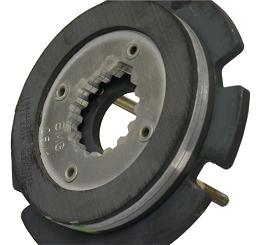

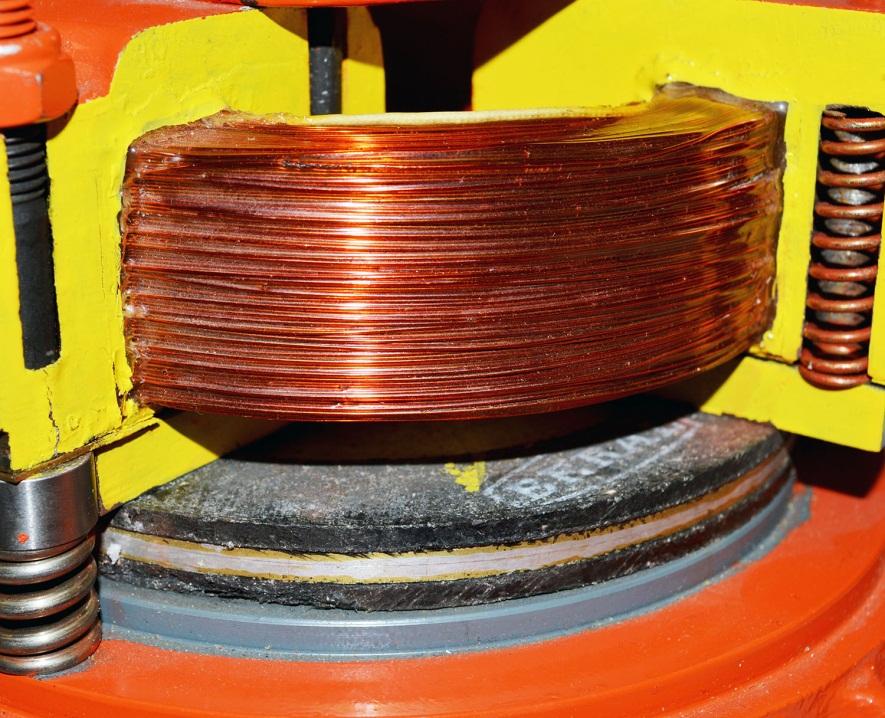
13 Brake Components Disc Disc Coil Spring Coil Spring 13

14 Brake Components Rectifiers and relays that mount in Motor Conduit Box 14

15 Brake Components Rectifiers that mount in Control Panel 15

16 Brake Components Typical brake wiring configuration 16


17 Troubleshooting Troubleshooting SEW brakes 17


18 Troubleshooting Always follow the proper lockout/tagout procedures Always use the proper safety equipment and PPE 18


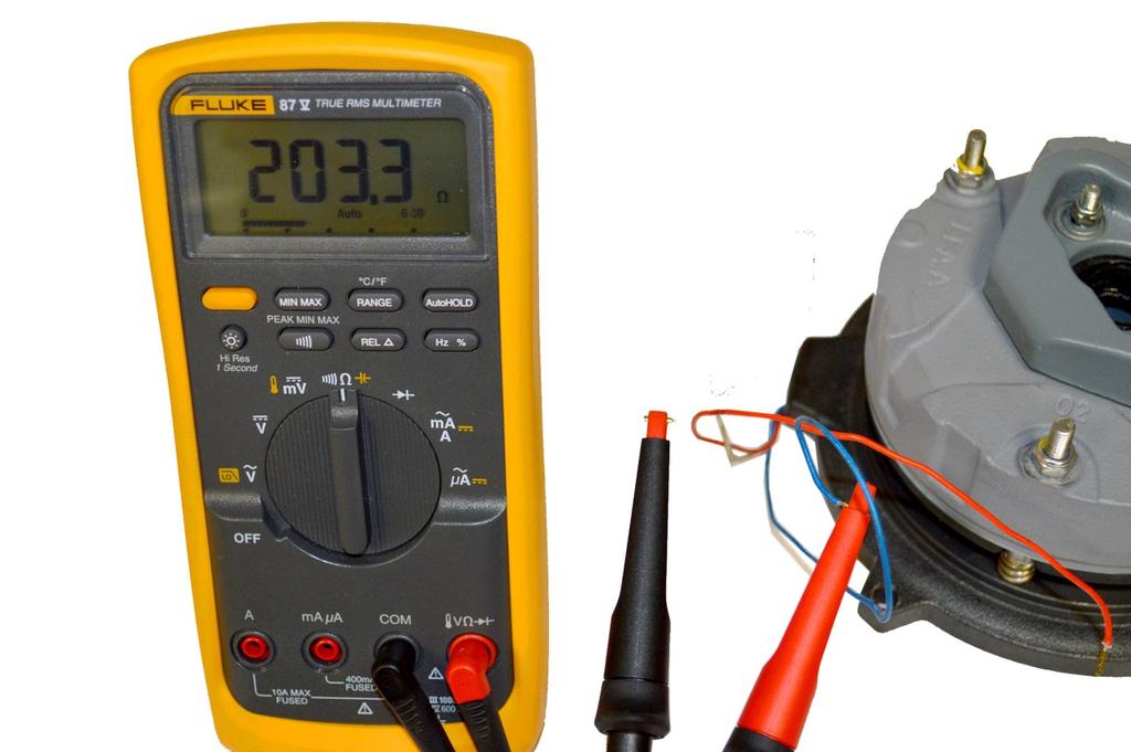
19 Troubleshooting Resources needed - Nameplate data from motor - Motor/Brakemotor operating instructions - Motor/Brakemotor parts list - Digital multi-meter - Metric nutdrivers - Metric feeler gauge 19
20 Troubleshooting Common faults - Rectifier is damaged. - Rectifier is wired incorrectly. - AC brake voltage is incorrect or not applied. - Brake coil is damaged or malfunctioning. - Brake is mechanically locked. - Air gap is outside of tolerance. - Brake disc is worn or damaged. 20

21 Troubleshooting - Rectifier Damaged rectifier - Incorrect voltage or wiring causes internal damage to rectifier - Check the rectifier in a de-energized state using the diode checker on your digital multi-meter - All power to diode must be OFF. Diode should be isolated from other components (all wires disconnected!) - Multi-meter must be in (diode checker mode) with the meter s black lead in the jack and the meter s red lead in the jack. - See chart on following page 21
22 Troubleshooting - Rectifier Brake Rectifier Diode Check Chart Type Black Lead to Red Lead to Terminal Terminal Good Reading BGE 1.5 / V dc V dc BG 1.5 / V dc V dc BSG V dc V dc V dc V dc BMK V dc V dc BME 1.5 / V dc V dc V dc V dc 22
23 Troubleshooting - Wiring Incorrect wiring - Refer to wiring diagram paperwork supplied with motor - Verify proper wiring using the sticker supplied with motor conduit box lid - Refer to the motor nameplate for the correct brake voltage 23

24 Troubleshooting - Wiring Check voltage at brake contactor - If rectifier power does not come from motor terminals, measure the voltage at the brake contactor Check the activation of the brake contactor - Verify that the brake contactor functions properly and changes position when energized 24


25 Troubleshooting - Coil Brake coil is damaged or malfunctioning - Wrong voltage applied to brake coil causes internal and external damage Coil received incorrect voltage 25

26 Troubleshooting - Coil Measure the actual resistances of accelerator coil and fractional coil (fractional coil) (accelerator coil) (total coil) Accelerator coil winding resistance Fractional coil winding resistance Total coil winding resistance = ¼ of winding resistance = ¾ of winding resistance = sum of accelerator and holding coil resistance 26
27 Troubleshooting - Coil Brake Coil Resistance Values Nominal voltage V N BE05 / BE1 BE2 BE5 BE11 BE20 BE30 / BE32 BE60 / BE62 BE120 / BE122 V AC V DC R B R T R B R T R B R T R B R T R B R T R B R T R B R T R B R T 24 (23-26) (57-63) ( ) ( ) ( ) ( ) ( ) ( ) ( ) ( ) ( ) ( ) ( ) ( ) ( ) R B accelerator coil resistance at 68 F in Ω R T coil section resistance at 68 F in Ω V N nominal voltage (nominal voltage range) 27
![Troubleshooting Hand Release Brake is mechanically locked - Verify the free play on the release arm - Adjust the locking nuts to achieve the correct floating clearance Brake Floating clearance s [mm]](/docs-images/95/125374399/images/28-3.jpg "BE05, BE1, BE2, BE5 1.5 BE11, BE20, BE30/32, BE60/62, BE120/122 2 Caution! There must always be clearance on the lever.")
28 Troubleshooting Hand Release Brake is mechanically locked - Verify the free play on the release arm - Adjust the locking nuts to achieve the correct floating clearance Brake Floating clearance s [mm] BE05, BE1, BE2, BE5 1.5 BE11, BE20, BE30/32, BE60/62, BE120/122 2 Caution! There must always be clearance on the lever. Note: The brake release mechanism is not used to change the brake s torque setting. 28

29 Troubleshooting Air Gap Out of tolerance brake air gap - Too much air gap and the brake will not release - Insufficient air gap and the brake will not release Air-gap 29
30 Troubleshooting Air Gap Obtain correct value for air gap Brake type Working air gap in / [mm] - Min. Max. BE05/BE1/BE2.01 / [0.25].024 / [0.60] BE5.01 / [0.25].035 / [0.90] BE11/BE20/BE30/BE / [0.30].047 / [1.20] BE32/BE / [0.40].047 / [1.20] BE / [0.60].047 / [1.20] BE / [0.80].047 / [1.20] Look up the correct values in the SEW Motor Operating Instructions 30
 between dampening")
 hex nuts until the feeler gauge feels snug")
31 Troubleshooting Air Gap Adjustment Method 1 1. Insert feeler gauge (minimum value set) between dampening plate and coil or between pressure plate and coil 2. Adjust (3) hex nuts until the feeler gauge feels snug equally around the brake 31


32 Troubleshooting Air Gap Adjustment Method 2 1. Tighten the three adjustment nuts equally to establish zero air gap 2. Loosen the adjustment nuts equally ½ turn 32

33 Troubleshooting Brake Disc Brake disc is worn or damaged - Sliding friction cause carbon based brake disc to wear - High cycle rates require more frequent disc replacement - Overheating can cause pressure plate to warp 33

34 Troubleshooting Brake Disc Check thickness of brake disc 1. Measure the thickness of the brake disc with calipers 2. Replace disc if out of tolerance 3. Reinstall new disc or current disc if within tolerance range Brake type Thickness in / [mm] BE05/BE1/BE2/BE5.354 / [9] BE11/BE20/BE30/BE32/BE60/BE / [10] BE120/BE / [12] 34
35 Conclusion This presentation provided a basic overview of SEW Brakes and should enable you to achieve the following 1. Describe the purpose of the SEW brake 2. Explain the operation of the SEW brake 3. Identify the components of an SEW brake 4. Apply basic troubleshooting procedures For more detail information and maintenance of SEW mechanical products please visit our website at 35
Operating Instructions
 Gearmotors \ Industrial Gear Units \ Drive Electronics \ Drive Automation \ Services BMG..T Double Disc Brakes for Stage Applications A6.C86 Edition 06/2004 11295228 / EN Operating Instructions SEW-EURODRIVE
ELECTRICAL. Contents - Wiring Diagrams
 Contents - Wiring Diagrams T-Bar (Floating Deck - Hydro)............................................ 8-16 T-Bar (Fixed Deck - Gear)............................................... 8-17 T-Bar (Fixed Deck
F O R M. Installation and Maintenance Manual for FCR Equipped Motors and Gearmotors. 9055E Revised October 2015
 Installation and Maintenance Manual for FCR Equipped Motors and Gearmotors Power Transmission Solutions Regal Beloit America, Inc. 7120 New Buffington Road Florence, KY 41042 Application Engineering: 800
Service and Maintenance. Repositioning of the Motor Conduit Box and Cable Entry Motor Frame Sizes
 Service and Maintenance Repositioning of the Motor Conduit Box and Cable Entry Motor Frame Sizes 71-132 Overview 1 2 3 4 Safety Tooling Changing the Conduit Box Position Changing the Cable Entry Safety
Jogging and Plugging of AC and DC Motors. Prepared by Engr. John Paul Timola, LPT
 Jogging and Plugging of AC and DC Motors Prepared by Engr. John Paul Timola, LPT Jogging sometimes called inching momentary operation of a motor for the purpose of accomplishing small movements of the
DIRACT BRAKES 70 SERIES 4 POST BRAKE INSTRUCTIONS
 Bulletin No. BK4605 (3/18) DIRACT BRAKES 70 SERIES 4 POST BRAKE INSTRUCTIONS IMPORTANT Read this bulletin carefully before installing or operating this brake. Failure to comply with these instructions
Installation Sheet January, 2016 Supersedes February, 2013
 s Installation Sheet January, 016 Supersedes February, 013 E87010-A0104-T003-A6-CLM0 Lighting and Heating Contactor 30 Amp, 3, 4, 5 Pole Magnetically Latched Description Magnetically latched CLM lighting
Installation and Service Instructions for Self Adjust Brakes 81,000 Series
 Spring-Set Disc Brakes P/N -07-9-00 effective 07/0/0 Installation and Service Instructions for Self Adjust Brakes,000 Series Current revision available @ www.stearns.rexnord.com Tools required for installation
Installation, Service and Parts List Series 56,800 for Class I & II, Division 2 Manual Adjust Brakes
 Spring-Set Disc Brakes P/N 8-078-905-8 effective /0/0 Installation, Service and Parts List Series 56,800 for Class I & II, Division Manual Adjust Brakes Tools required for installation and servicing: /8
Installation and Service Instructions for Self Adjust Brakes 82,000 Series
 Spring-Set Disc Brakes P/N 8-078-9-00 effective 0// Installation and Service Instructions for Self Adjust Brakes 8,000 Series Current revision available @ www.rexnord.com/stearns Figure Tools required
Tech Note Truck 14 & 15.5 Twin Plate Cast Iron Type Installation Guidelines
 1. (14 & 15.5 ) Check condition of the flywheel. Grind to resurface or replace flywheel. Surface MUST BE machined or premature clutch failure can occur. Flywheel depth must be 2.938 (74.62mm) for 14 (350mm)
Operating and maintenance handbook Brake motors series CCL
 Operating and maintenance handbook Brake motors series CCL Rev. 01 SAFETY BRAKE SERIES CCL Specifications of the brake series CCL The electromechanic spring brake series CCL is a direct current brake.
MSW020/025-E [A895]; MPB040-E [B827]; MPW045-E [B802]; MPW050-E [C802] PART NO YRM
![MSW020/025-E [A895]; MPB040-E [B827]; MPW045-E [B802]; MPW050-E [C802] PART NO YRM](/thumbs/84/91174859.jpg "MSW020/025-E [A895]; MPB040-E [B827]; MPW045-E [B802]; MPW050-E [C802] PART NO YRM") Maintenance BRAKES MSW020/025-E [A895]; MPB040-E [B827]; MPW045-E [B802]; MPW050-E [C802] PART NO. 524154893 1800 YRM 1005 SAFETY PRECAUTIONS MAINTENANCE AND REPAIR When lifting parts or assemblies, make
Maintenance BRAKES MSW020/025-E [A895]; MPB040-E [B827]; MPW045-E [B802]; MPW050-E [C802] PART NO. 524154893 1800 YRM 1005 SAFETY PRECAUTIONS MAINTENANCE AND REPAIR When lifting parts or assemblies, make
SHORT-STOP. Electronic Motor Brake Type G. Instructions and Setup Manual
 Electronic Motor Brake Type G Instructions and Setup Manual Table of Contents Table of Contents Electronic Motor Brake Type G... 1 1. INTRODUCTION... 2 2. DESCRIPTION AND APPLICATIONS... 2 3. SAFETY NOTES...
D58 Series Brake Instructions
 D58 Series Brake Instructions 4740 W. Electric Avenue Milwaukee, WI 53219 414/672-7830 FAX 414/672-5354 www. dingsbrakes.com Safety information 2 Safety information 2.1 Persons responsible for the safety
GROUP 35A 35A-1 CONTENTS GENERAL DESCRIPTION... 35A-3 BASIC BRAKE SYSTEM DIAGNOSIS 35A-6 HYDRAULIC BRAKE BOOSTER (HBB) DIAGNOSIS...
 DIAGNOSIS...") 35A-1 GROUP 35A CONTENTS GENERAL DESCRIPTION......... 35A-3 DIAGNOSIS 35A-6 INTRODUCTION..................... 35A-6 DIAGNOSTIC TROUBLESHOOTING STRATEGY......................... 35A-6 SYMPTOM CHART...................
35A-1 GROUP 35A CONTENTS GENERAL DESCRIPTION......... 35A-3 DIAGNOSIS 35A-6 INTRODUCTION..................... 35A-6 DIAGNOSTIC TROUBLESHOOTING STRATEGY......................... 35A-6 SYMPTOM CHART...................
Lesson 5: Directional Control Valves
 : Directional Control Valves Basic Hydraulic Systems Hydraulic Fluids Hydraulic Tank Hydraulic Pumps and Motors Pressure Control Valves Directional Control Valves Flow Control Valves Cylinders : Directional
CR193 Vacuum Limitamp* Contactors
 GE Electrical Distribution GEH-5306C Maintenance Instructions CR193 Vacuum Limitamp* Contactors Contents Section 1 Introduction... 3 General... 3 Section 2 Description... 4 Principle of Operation... 4
Installation Sheet January, 2016 Supersedes June 2013
 s Installation Sheet January, 016 Supersedes June 01 E87010-A0105-T00-A6-CLM0 Lighting and Heating Contactor 60, 100, 00 Amp,, 4, 5 Pole Magnetically Latched Description Magnetically latched CLM lighting
Exercise 4-1. Friction Brakes EXERCISE OBJECTIVE DISCUSSION. Understand the construction and operation of friction brakes.
 Exercise 4-1 Friction Brakes EXERCISE OBJECTIVE Understand the construction and operation of friction brakes. DISCUSSION Friction brakes, or magnetic brakes, are used to secure (hold) the position of a
BASIC BRAKE SYSTEM GROUP 35A 35A-1 CONTENTS GENERAL DESCRIPTION... 35A-3 BASIC BRAKE SYSTEM DIAGNOSIS 35A-6
 35A-1 GROUP 35A BASIC BRAKE SYSTEM CONTENTS GENERAL DESCRIPTION......... 35A-3 DIAGNOSIS 35A-6 INTRODUCTION..................... 35A-6 DIAGNOSTIC TROUBLESHOOTING STRATEGY......................... 35A-6
8 BK brakes. 8.1 Description of BK brakes (CMP40 to CMP63) Description of BK brakes (CMP40 to CMP63)
 Description of BK brakes (CMP40 to CMP63)") 8 BK brakes Description of BK brakes (CMP0 to CMP6) 8 BK brakes 8. Description of BK brakes (CMP0 to CMP6) The mechanical brake is a holding brake implemented as a permanent magnet brake. The standard
8 BK brakes Description of BK brakes (CMP0 to CMP6) 8 BK brakes 8. Description of BK brakes (CMP0 to CMP6) The mechanical brake is a holding brake implemented as a permanent magnet brake. The standard
CAUTION. Hydraulic Brakes. Braking Systems - Hydraulic
 Hydraulic Brakes Dexter offers several varieties of hydraulic trailer brakes. Your vehicle may be equipped with drum brakes or disc brakes. The hydraulic brakes on your trailer are much like those on your
Starting and Charging
 The Starting and Charging System is a critical system in your vehicle. The Starting system provides the ability to crank the engine electrically from the drivers position. The first car with electric starting
ABB ! CAUTION. Type KRV Directional Overcurrent Relay E 1.0 APPLICATION 2.0 CONSTRUCTION AND OPERATION. Instruction Leaflet
 ABB Instruction Leaflet 41-137.2E Effective: February 1994 Supersedes I.L. 41-137.2D, Dated February 1973 ( )Denotes Change Since Previous Issue. Type KRV Directional Before putting relays into service,
CARLYLE JOHNSON MAXITORQ MODEL FEA CLUTCH, SPRING APPLIED - ELECTRICALLY RELEASED MAINTENANCE REPAIR TROUBLESHOOTING MANUAL
 CARLYLE JOHNSON MAXITORQ MODEL FEA CLUTCH, SPRING APPLIED - ELECTRICALLY RELEASED MAINTENANCE REPAIR TROUBLESHOOTING MANUAL The Carlyle Johnson Machine Company, LLC 291 Boston Turnpike / P O Box 9546 /
3.0 CHARACTERISTICS E Type CO-4 Step-Time Overcurrent Relay
 41-106E Type CO-4 Step-Time Overcurrent Relay A core screw accessible from the top of the switch provides the adjustable pickup range. The IIT contacts are connected in the trip circuit to trip instantaneously.
Electric Brakes. Braking Systems - Electric
 Electric Brakes The electric brakes on your trailer are similar to the drum brakes on your automobile. The basic difference is that your automotive brakes are actuated by hydraulic pressure while your
L. Photo. Figure 2: Types CA-16 Relay (rear view) Photo. Figure 1: Types CA-16 Relay (front view)
 Photo. Figure 1: Types CA-16 Relay (front view)") Figure 1: Types CA-16 Relay (front view) Photo Figure 2: Types CA-16 Relay (rear view) Photo 2 Sub 5 185A419 Sub 6 185A443 Figure 3: Internal Schematic of the Type CA-16 bus Relay or CA-26 Transformer
Figure 1: Types CA-16 Relay (front view) Photo Figure 2: Types CA-16 Relay (rear view) Photo 2 Sub 5 185A419 Sub 6 185A443 Figure 3: Internal Schematic of the Type CA-16 bus Relay or CA-26 Transformer
PREVIEW ONLY. Course 106 INSTRUCTOR GUIDE. HVAC Systems Introduction and Overview. Module 1: Overview of Rail Car HVAC and General Safety Procedures
 Course 106 HVAC Systems Introduction and Overview Module 1: Overview of Rail Car HVAC and General Safety Procedures INSTRUCTOR GUIDE Table of Contents CHECKLIST FOR INSTRUCTION... 3 SUPPLIES, AUDIO-VISUAL
17429X.00 SERIES MODELS:
 LEESON ELECTRIC MOTORS, GEARMOTORS AND DRIVES R User s Manual 17429X.00 SERIES MODELS: 174298.00 174299.00 PWM REGENERATIVE DC TO DC DRIVES II Table of Contents 17429X.00 Drives...............................................................
2.0 CONSTRUCTION AND OPERATION 3.0 CHARACTERISTICS K. CO (HI-LO) Overcurrent Relay
 Overcurrent Relay") 41-100K 2.0 CONSTRUCTION AND OPERATION The type CO relays consist of an overcurrent unit (CO), either an Indicating Switch (ICS) or an ac Auxiliary Switch (ACS) and an Indicating Instantaneous Trip unit
41-100K 2.0 CONSTRUCTION AND OPERATION The type CO relays consist of an overcurrent unit (CO), either an Indicating Switch (ICS) or an ac Auxiliary Switch (ACS) and an Indicating Instantaneous Trip unit
Installation and Service Instructions for 87,000 & 87,100 Series Self-Adjust Brakes (rev. B)
") Spring-Set Disc Brakes P/N 8-078-98-0 effective 6/6/0 Installation and Service Instructions for 87,000 & 87,00 Series Self-Adjust Brakes (rev. B) Tools required for installation and servicing: 3/8 hex
Spring-Set Disc Brakes P/N 8-078-98-0 effective 6/6/0 Installation and Service Instructions for 87,000 & 87,00 Series Self-Adjust Brakes (rev. B) Tools required for installation and servicing: 3/8 hex
MOTOR CONTROLLERS. STATE the function of motor controllers.
 Electrical Distribution Systems Motor controllers range from a simple toggle switch to a complex system using solenoids, relays, and timers. The basic functions of a motor controller are to control and
Exercise 5-1. Primary Resistor Starters EXERCISE OBJECTIVE DISCUSSION. Understand how primary resistor starters operate.
 Exercise 5-1 Primary Resistor Starters EXERCISE OBJECTIVE Understand how primary resistor starters operate. DISCUSSION High starting torque can result in sudden acceleration and damage to the driven machinery.
Installation, Operation and Maintenance Instructions
 VM-3153B Installation, Operation and Maintenance Instructions Vibratory feeder model 26C ERIEZ MAGNETICS HEADQUARTERS: 2200 ASBURY ROAD, ERIE, PA 16506 1402 U.S.A. WORLD AUTHORITY IN ADVANCED TECHNOLOGY
Installation and Service Instructions for 87,000 Series Manual Adjust Brakes (rev. B)
") Spring-Set Disc Brakes P/N 8-078-98-06 effective /7/ Installation and Service Instructions for 87,000 Series Manual Adjust Brakes (rev. B) Tools required for installation and servicing: 3/8 hex wrench
Spring-Set Disc Brakes P/N 8-078-98-06 effective /7/ Installation and Service Instructions for 87,000 Series Manual Adjust Brakes (rev. B) Tools required for installation and servicing: 3/8 hex wrench
ANTI-LOCK BRAKES. Section 9. Fundamental ABS Systems. ABS System Diagram
 ANTI-LOCK BRAKES Fundamental ABS Systems Toyota Antilock Brake Systems (ABS) are integrated with the conventional braking system. They use a computer controlled actuator unit, between the brake master
Bulletin: CLIB Date: February 4, Bulletin Type: Service. Topic: Eaton Clutch Performance Evaluation and Set-up
 Bulletin: CLIB-0014 Date: February 4, 2011 Bulletin Type: Service Topic: Eaton Clutch Performance Evaluation and Set-up Issue Description: The purpose of communicating this information is to provide details
INSTALLATION GUIDE CRF150R Manual Revision:
 REKLUSE MOTOR SPORTS The z-start Pro Clutch INSTALLATION GUIDE CRF150R 191-810 Manual Revision: 032508 2002 Rekluse Motor Sports Rekluse Motor Sports, Inc. 110 E. 43rd Street Boise, Idaho 83714 208-426-0659
2015 EDITION SUBMERSIBLE MOTORS AIM MANUAL. APPLICATION INSTALLATION MAINTENANCE 60 Hz, Single-Phase and Three-Phase Motors. franklinwater.
 0 EDITION AIM MANUAL SUBMERSIBLE MORS APPLICATION INSTALLATION 60 Hz, Single-Phase and Three-Phase Motors franklinwater.com All Motors System Troubleshooting Motor Does Not Start A. No power or incorrect
A - Add New Information C - Change Existing Information D - Delete Information. Page 7. Delete the fourth paragraph beginning CAUTION
 ABB Effective: November 1990 This Addendum Supersedes all Previous Addenda Addendum to Instruction Leaflet 41-137.3H Type KRD-4 Directional Overcurrent Ground Relay A - Add New Information C - Change Existing
Hydraulic Brake System, Bosch 42.15
 Hydraulic Brake System, Bosch 42.15 Index Hydraulic Brake Index Subject Figure Brake warning lamp and buzzer related to parking brake Fig. 1 Brake warning lamp and buzzer related to service brake Fig.
Battery Operation. Battery Construction. Battery State Of Charge. Battery Load Test. Battery Rating Systems 2/14/12
 Battery Operation Batteries, Charging and Donald Jones Brookhaven College Batteries convert chemical energy into electrical energy During discharge the battery s plate composition is changed During charging
INSTRUCTION INFORMATION FOR TYPE "DB" ELECTRIC DISC BRAKE (DB-0, DB-2, DB-4)
") The Last Word in Cranes INSTRUCTION INFORMATION FOR TYPE "DB" ELECTRIC DISC BRAKE (DB-0, DB-2, DB-4) OPERATION Zenar's type "DB" brakes are classified as a holding or parking type electro-mechanical operated
The Last Word in Cranes INSTRUCTION INFORMATION FOR TYPE "DB" ELECTRIC DISC BRAKE (DB-0, DB-2, DB-4) OPERATION Zenar's type "DB" brakes are classified as a holding or parking type electro-mechanical operated
7 Brake and backstop. 7.1 BE.. brake from SEW EURODRIVE. BE.. brake from SEW EURODRIVE
 and backstop BE.. brake from SEW EURODRIVE and backstop On request, SEW EURODRIVE motors can be supplied with an integrated mechanical brake or backstop. The BE.. brake is part of SEW EURODRIVE's modular
70 Series 8700 End Mount Three Phase Brake Instructions IP43 (NEMA 2) Housing
 Housing") Bulletin No. BK4772S-3 (6/2017) 70 Series 8700 End Mount Three Phase Brake Instructions IP43 (NEMA 2) Housing Read carefully before attempting to assemble, install, operate or maintain the product described.
Bulletin No. BK4772S-3 (6/2017) 70 Series 8700 End Mount Three Phase Brake Instructions IP43 (NEMA 2) Housing Read carefully before attempting to assemble, install, operate or maintain the product described.
INSTALLATION & USER S GUIDE
 REKLUSE MOTOR SPORTS The Rekluse Core EXP Kit for Kawasaki KX80/85/100 OVERVIEW INSTALLATION & USER S GUIDE Doc ID: 191-7742A Doc Rev: 073015 This kit replaces the OEM core clutch components including
Electrically Released Brakes ERS VAR11-01 FT = 4100 N
 SM429gb - rev 06/11 S E R V I C E Electrically Released Brakes ERS VAR11-01 FT = 4100 N M A N U A L EC type certificate ABV 775/1 According to drawing 1 12 106946 TUV SUD Industrie Service WARNER ELECTRIC
EXPERIMENT 2 THREE PHASE INDUCTION MOTOR, PART 1
 University f Jordan School of Engineering Department of Mechatronics Engineering Electrical Machines Lab Eng. Osama Fuad Eng. Nazmi Ashour EXPERIMENT 2 THREE PHASE INDUCTION MOTOR, PART 1 OBJECTIVES To
CIRCLE SEAL CONTROLS
 CIRCLE SEAL CONTROLS ATKOMATIC SOLENOID VALVES INSTALLATION, MAINTENANCE, AND OPERATION INSTRUCTIONS 13000 SERIES Stainless, Normally Closed, Direct Lift, 3-Way Valve Installation Instructions WARNING:
SUREPOWR TM SERIES -SURE 24/25 FIELD INSTALLATION INSTRUCTIONS
 SUREPOWR TM SERIES -SURE 4/5 FIELD INSTALLATION INSTRUCTIONS Safety First In the maintenance and operation of mechanical equipment, SAFETY is the basic factor which must be considered at all times. Through
1. SPECIFICATION
 000000 093 1. SPECIFICATION Specification HPS EPS Alternator Crankshaft pulley : Alternator Pulley 1 : 2.94 Normal output (idling/2200 rpm) 70/120 A 70/140A Regulator voltage 14.6 V Brush Length 12.5 mm
REAR AXLE GROUP CONTENTS GENERAL DESCRIPTION REAR AXLE DIAGNOSIS REAR AXLE HUB ASSEMBLY KNUCKLE...
 27-1 GROUP 27 CONTENTS GENERAL DESCRIPTION......... 27-2 DIAGNOSIS......... 27-2 INTRODUCTION TO DIAGNOSIS........................ 27-2 DIAGNOSTIC TROUBLESHOOTING STRATEGY...... 27-2 SYMPTOM CHART...................
Characteristics of model K brake
 Characteristics of model K brake The brake model K is a spring applied d.c. brake. It has been designed to stop rotational movement of machine shaft. However the user has to ensure that the brake is in
REAR SUSPENSION GROUP CONTENTS GENERAL DESCRIPTION TRAILING ARM ASSEMBLY REAR SUSPENSION DIAGNOSIS
 34-1 GROUP 34 CONTENTS GENERAL DESCRIPTION......... 34-2 DIAGNOSIS.. 34-3 INTRODUCTION TO DIAGNOSIS........................ 34-3 DIAGNOSIS TROUBLESHOOTING STRATEGY...... 34-3 SYMPTOM CHART...................
Relay. for Experiments with the fischertechnik Expansion Kit. Order No
 Relay for Experiments with the fischertechnik Expansion Kit Order No. 30075 About the Relay A relay is an electromagnetic switch. It consists essentially of two assemblies. 5 6 7 3 2 1. Technical Data
COMBIBOX Program Schedule. Design. COMBIBOX Clutch-brake-combination type 10 / 09 / 06. Attachments input
 COMBIBOX Program Schedule COMBIBOX Clutch-brake-combination type 10 / 09 / 06 with an energised to engage single sided clutch / brake COMBIBOX 10 page 37 with an energised to engage single sided clutch
Service Instructions. Syntron Vibrating Feeder Model: RS-A Velocity TM
 Service Instructions Syntron Vibrating Feeder Model: RS-A Velocity TM Service Manual Syntron Vibrating Feeder Model: RS-A Velocity TM 1 Table of Contents GENERAL Page Safety Instructions 3 Introduction
Chapter 8. Understanding the rules detailed in the National Electrical Code is critical to the proper installation of motor control circuits.
 Chapter 8 Understanding the rules detailed in the National Electrical Code is critical to the proper installation of motor control circuits. Article 430 of the NEC covers application and installation of
DIFFERENTIALS & AXLE SHAFTS
 DIFFERENTIALS & AXLE SHAFTS 2001 Chevrolet Camaro 2000-01 DRIVE AXLES General Motors Differentials & Axle Shafts Chevrolet; Camaro Pontiac; Firebird DESCRIPTION & OPERATION Drive axle is a semi-floating,
70 Series 8700 End Mount Three Phase Brake Instructions IP56 (NEMA 4) Housing
 Housing") Bulletin No. BK4773-3 (08/2016) 70 Series 8700 End Mount Three Phase Brake Instructions IP56 (NEMA 4) Housing Read carefully before attempting to assemble, install, operate or maintain the product described.
Bulletin No. BK4773-3 (08/2016) 70 Series 8700 End Mount Three Phase Brake Instructions IP56 (NEMA 4) Housing Read carefully before attempting to assemble, install, operate or maintain the product described.
Chapter 10: Installation Considerations / Troubleshooting
 Chapter 10: Installation Considerations / Troubleshooting Objectives Introduction The objectives for this chapter are as follows: Understand the proper method of installing the coil. Walk through the steps
60 Series End-Mount Brake Instructions Standard Housing
 Bulletin No. BK4655 (04/18) 60 Series End-Mount Brake Instructions Standard Housing Read carefully before attempting to assemble, install, operate or maintain the product described. Protect yourself and
Stromag Dessau. safety in motion PRODUCT CATALOGUE. NFF4F-LS Brake. for Slow-Running High Torque Drivelines, in harsh environment
 Stromag Dessau safety in motion PRODUCT CATALOGUE NFF4F-LS Brake for Slow-Running High Torque Drivelines, in harsh environment ENGINEERING THAT MOVES THE WORLD Applications Holding brake variations with
Installation and Service Instructions for 87,000 & 87,100 Series Self-Adjust Brakes (rev. B)
") Spring-Set Disc Brakes P/N 8-078-98-0 effective 03/6/4 Installation and Service Instructions for 87,000 & 87,00 Series Self-Adjust Brakes (rev. B) Tools required for installation and servicing: 3/8 hex
Spring-Set Disc Brakes P/N 8-078-98-0 effective 03/6/4 Installation and Service Instructions for 87,000 & 87,00 Series Self-Adjust Brakes (rev. B) Tools required for installation and servicing: 3/8 hex
COMBIBOX. Program Schedule. Design. COMBIBOX clutch-brake-combination type 10 / 09 / 06. Attachments
 clutch-brake-combination 10 / 09 / 06 with an energised to engage single sided clutch / brake... 10 with an energised to engage single sided clutch without brake... 09 with an energised to engage single
FG MACH I / MACH IIA OWNER S MANUAL AUTOMATIC BULK FEED PINSPOTTER MACHINERY DIVISION
 FG MACH I / MACH IIA AUTOMATIC BULK FEED PINSPOTTER MACHINERY DIVISION OWNER S MANUAL INTRODUCTION The FG Mach I and Mach IIA Pinspotters were designed utilizing the best current technology to provide
A/C COMPRESSOR SERVICING Article Text 1991 Saab 9000 For Copyright 1997 Mitchell International Friday, October 15, :22PM
 Article Text ARTICLE BEGINNING 1991 GENERAL SERVICING Compressor Service * PLEASE READ THIS FIRST * CAUTION: When discharging air conditioning system, use only approved refrigerant recovery/recycling equipment.
1. SPECIFICATION Typ. HPS EPS Capacity 120 A 140 A. 76/140 A at 1,800/6,500 rpm. 70/120 A at 1,800/6,500 rpm. Normal output.
 145300 093 1. SPECIFICATION Typ. HPS EPS Capacity 120 A 140 A Alternator Battery Normal output 70/120 A at 1,800/6,500 rpm 76/140 A at 1,800/6,500 rpm Regulator voltage 14.6 V Brush Length 12.5 mm Wear
REAR SUSPENSION GROUP CONTENTS GENERAL DESCRIPTION REAR SUSPENSION DIAGNOSIS LOWER ARM AND TOE CONTROL ARM ASSEMBLY...
 34-1 GROUP 34 CONTENTS GENERAL DESCRIPTION........... 34-2 DIAGNOSIS.... 34-2 INTRODUCTION....................... 34-2 TROUBLESHOOTING STRATEGY........ 34-2 SYMPTOM CHART..................... 34-3 SYMPTOM
Model 2300JL Installation Guide
 Model 2300JL Installation Guide POWER ACCESS CORPORATION 4 HERSHEY DRIVE, DOCK 4 ANSONIA, CT 06401 800-344-0088 WEBSITE: www.power-access.com EMAIL: salesinfo@power-access.com 1 STANDARD PARTS MODEL 2300JL
Features IN THIS CHAPTER
 CHAPTER THREE 3Special Features IN THIS CHAPTER Motor Braking Regeneration Solutions Sharing the Power Bus: V Bus+ and V Bus- Current Foldback (I T Limit) Front Panel Test Points Resolver Alignment ➂ Special
USER S GUIDE Manual Revision:
 REKLUSE MOTOR SPORTS The Rekluse Core EXP Clutch USER S GUIDE 193-297 Manual Revision: 051509 2009 Rekluse Motor Sports Rekluse Motor Sports, Inc. 110 E. 43rd Street Boise, Idaho 83714 208-426-0659 support@rekluse.com
BELT-DRIVEN ALTERNATORS
 CHAPTER 13 BELT-DRIVEN ALTERNATORS INTRODUCTION A generator is a machine that converts mechanical energy into electrical energy using the principle of magnetic induction. This principle is based on the
Characteristics of model T-Mec brake
 Characteristics of model T-Mec brake These traditional AC brakes, besides their tested reliability, have the following characteristics: Very strong structure; Quick operating times. They can be considered
Installation and Operating Instructions for ROBA-stop -Positioning Brake Type 80_.41_._ Sizes 3 11
 Please read and observe this Operating Instruction carefully! A possible malfunction or failure of the brake and any damage may be caused by not observing it. Table of contents: Page 1: Page 2: Page 3:
Timer. TipTop Timers. Installation and Operation Manual
 TipTop s E TM Installation and Operation Manual Sold by: TipTop s LLC 2225 North Dollar Road Spokane Valley, WA 99212 web: Model T Electronic - E E Conversion Kit Contents The Electronic conversion kit
BALDOR MN413 Brakes Manual
 BALDOR MN413 Brakes Manual http://www.manuallib.com/baldor/mn413-brakes-manual.html The DODGE D-Series motor brakes are manufactured to NEMA standards for mounting to C-face and double shafted motors.
SERVICE SHOP NOTES. Use ohmmeter to check the resistance between the leads.
 SERVICE SHOP NOTES LIMA MAC SELF VOLTAGE REGULATED GENERATORS Troubleshooting Tips Symptom: Engine bogs down or stalls even at no load. Problem: Main stator has one or more taps wound or connected incorrectly.
feeder Vibratory feeder
 VM-3155C Installation, Operation and Maintenance Instructions Vibratory feeder model hs36 Vibratory feeder model 36C ERIEZ MAGNETICS HEADQUARTERS: 2200 ASBURY ROAD, ERIE, PA 16506 1402 U.S.A. WORLD AUTHORITY
CLAAS JAGUAR SYSTEM FAULT CODES. Code Module Fault Operating state Troubleshooting
 CLAAS JAGUAR SYSTEM FAULT CODES https://truck-manuals.jimdo.com/claas-fault-codes/ Code Module Fault Operating state Troubleshooting E-1 Device oil pressure engine too poor E-2 device Oil Level engine
2006 MINI Cooper S GENINFO Starting - Overview - MINI
 MINI STARTING SYSTEM * PLEASE READ THIS FIRST * 2002-07 GENINFO Starting - Overview - MINI For information on starter removal and installation, see the following articles. For Cooper, see STARTER WITH
SUREPOWR TM SERIES -SURE 49 FIELD INSTALLATION INSTRUCTIONS
 SUREPOWR TM SERIES -SURE 49 FIELD INSTALLATION INSTRUCTIONS Safety First In the maintenance and operation of mechanical equipment, SAFETY is the basic factor which must be considered at all times. Through
COOKSON OWNER S MANUAL
 COOKSON OWNER S MANUAL ELECTRIC CLUTCH RELEASE FOR TUBULAR MOTOR 3117(1) ECN 0951 BY RG 10/28/10 1 PATENT NO. 6,155,324 SPECIFICATIONS ELECTRICAL SPECIFICATIONS TUBULAR MOTOR FOR TUBULAR MOTOR ELECTRICAL
section-page Table 1. Transfer switching device ratings. Conditional short circuit current
 Operator s Manual 7000 Series ATS Automatic Transfer Switching Equipment D design 30 through 200 amperes TABLE OF CONTENTS section-page INSTALLATION... 1-1 Enclosures and Mounting... 1-1 Power Connections...
Surepowr Series Sure 150
 RCS Acutators Surepowr Series Sure 50 Installation Manual Safety First In the maintenance and operation of mechanical equipment, safety is the basic factor which must be considered at all times. Through
CIRCLE SEAL CONTROLS
 CIRCLE SEAL CONTROLS ATKOMATIC SOLENOID VALVES INSTALLATION, MAINTENANCE, AND OPERATION INSTRUCTIONS 3000 SERIES Bronze, Normally Closed, Direct Lift Installation Instructions WARNING: These instructions
Surepowr Series 100 Installation Manual
 Surepowr Series 100 Installation Manual Safety First In the maintenance and operation of mechanical equipment, safety is the basic factor which must be considered at all times. Through the use of the proper
TEST CHART. Voltage Supply
 ALL MEASUREMENTS ARE MADE ON THE TERMINALS OF THE DISCONNECTED WIRING HARNESS PLUG TO THE CONTROL UNIT (ECU) WITH IGNITION OFF UNLESS OTHERWISE INDICATED. Voltage Supply Ignition Voltage supply to the
Exercise 1-5. Current Protection Devices EXERCISE OBJECTIVE DISCUSSION OUTLINE DISCUSSION. Circuit breakers
 Exercise 1-5 Current Protection Devices EXERCISE OBJECTIVE Describe and test the operation of circuit breakers, fuses, and overload relays. DISCUSSION OUTLINE The Discussion of this exercise covers the
Warner Electric UNIBRAKE Motor Brakes
 P-1699-WE Warner Electric UNIBRAKE Motor Brakes Installation & Operating Instructions Double C Contents General Information........................ 2 Brake Heads............................. 2 Installation...............................
Instructions for Continued Airworthiness
 . Instructions for Continued Airworthiness for the installation of THE GROVE DISC BRAKE CONVERSION in all PIPER AIRCRAFT INCLUDED IN THE FAA APPROVED MODEL LIST when installed In Accordance With Supplemental
ST Charger. Industrial Battery Charger
 ST Charger Industrial Battery Charger Installation and Operation Manual ST_13 Table of Contents Pg# 1.0 INSTALLATION 1 1.1 Receiving 1 1.2 Location 1 1.3 Line Voltage 1 1.4 A.C. Service Requirements 2
70 Series 8700 Coupler 2-pc Hub & Shaft Three Phase Brake Instructions IP43 & IP56 (NEMA 2 & 4) Housing
 Housing") Bulletin No. BK4775-3 (08/2016) 70 Series 8700 Coupler 2-pc Hub & Shaft Three Phase Brake Instructions IP43 & IP56 (NEMA 2 & 4) Housing Read carefully before attempting to assemble, install, operate or
Bulletin No. BK4775-3 (08/2016) 70 Series 8700 Coupler 2-pc Hub & Shaft Three Phase Brake Instructions IP43 & IP56 (NEMA 2 & 4) Housing Read carefully before attempting to assemble, install, operate or
ELECTROMAGNETIC DISC BRAKES H2SP SERIES WITH CONSTANT BRAKING TORQUE
 ELECTROMAGNETIC DISC BRAKES SERIES WITH CONSTANT BRAKING TORQUE K-EN--20151203 TD 223a Spring actuated and electromagnetically released disk brake type powered by direct current. Designed for braking rotating
The galvanic separation of the primary or actuating circuit and the load circuits
 RELAY BASICS Relays are electro magnetically operated switches. An actuating current on a coil operates one or more galvanically separated contacts or load circuits. The electro mechanical relay is a remote
McCANNA Actuation Systems B
 17710-B Ramcon Series 8/25 C/CR, 50/100 B/BR, 250/500 B/BR Electric Actuators Installation, Operation and Maintenance Instructions Contents Storage...........................................................................................................
Assembly Instructions: Conventional Motor (Beakman's Motor Kit)
") Assembly Instructions: Conventional Motor (Beakman's Motor Kit) 1. Leave about 3" (7-8cm) and wind the wire 10-35 times around the AA battery. You do not have to be neat as some randomness does not affect
Assembly Instructions: Conventional Motor (Beakman's Motor Kit) 1. Leave about 3" (7-8cm) and wind the wire 10-35 times around the AA battery. You do not have to be neat as some randomness does not affect
Garden Tractor Clutch
 P-1097-6 819-0458 Garden Tractor Clutch Troubleshooting and Installation Guide Contents Terminology........................... 2 Troubleshooting Checklist................ 3 Electrical Evaluation.....................