Chapter 8. Understanding the rules detailed in the National Electrical Code is critical to the proper installation of motor control circuits.
|
|
|
- Molly Golden
- 5 years ago
- Views:
Transcription

1 Chapter 8 Understanding the rules detailed in the National Electrical Code is critical to the proper installation of motor control circuits. Article 430 of the NEC covers application and installation of motor circuits. 1


2 A motor branch-circuit includes the final overcurrent device, the motor starter and associated control circuits, circuit conductors and the motor. Final Overcurrent Devices Starter And Control Circuits Circuit Conductors Motor Motor Branch Circuit Sections CONTACTOR M OL OVERLOAD RELAY M M OL OL MT R CIRCUIT BREAKER STOP START OLs M M 2


3 The full-load current rating shown on the motor nameplate is not permitted to be used to determine the ampacity of the conductors switches motor branch-circuit short-circuit and ground-fault protection. The reasons are: The supply voltage normally varies from the voltage rating of the motor, and the current varies with the voltage applied. The actual full-load current rating for motors of the same horsepower may vary, and requiring the use of NEC tables ensures that if a motor must be replaced, this can be safely done without having to make changes to other component parts of the circuit. Conductor ampacity must be determined by NEC Tables through and are based upon the motor nameplate horsepower rating and voltage. Overload protection, however, is based on the marked motor nameplate rating. 3
4 BRANCH CIRCUIT MOTOR PROTECTION Motor Branch Circuit Protection This arrangement makes motor protection calculations different from those used for other types of loads. 4


5 Time-delay fuses provide overload and short circuit protection usually allowing five times the rated current for up to ten seconds to allow motors to start. Nontime-delay fuses provide short circuit protection usually allowing about five times of their rating for approximately onefourth second, after which the currentcarrying element melts. The amount of time it takes for a fuse to open is known as the clearing time. Fuses have an inverse time characteristic. The greater the overcurrent, the less the clearing time. A motor overload condition is caused by excessive load applied to the motor shaft. For example, when using a saw, if the board is damp or the cut is too deep, the motor may become overloaded and slow down. The current flow in the windings will increase and heat the motor beyond its design temperature. Overloaded Motor Fuses do not blow Fuses are large enough to allow starting current Additional overload protection required 5

6 Motors are required to have overload protection, either within the motor itself or somewhere in close proximity to the line side of the motor. This overload protection is actually protecting the motor, the conductors, and much of the circuit ahead of the overloads. An overload in the circuit would trip the circuit overload devices, thus protecting the circuit from overload conditions. Motor control circuits carry the current that controls the operation of the controller, but do not carry the main power current to the motor. Main Power Current Control Current 6


7 SELECTING A MOTOR CONTROLLER A motor controller is any device that is used to directly start and stop an electric motor by closing and opening the main power current to the motor. The magnetic starter consisting of a contactor and overload relay is considered to be a controller. 7
8 The controller can be a switch, starter or other similar type of control device. Controller This is the basic rule MTR Fused switch or circuit breaker MTR Certain stationary motors up to 1/3 HP Cord cap serves as controller MTR Portable motors up to 1/3 HP Switch Circuit breaker rated in amps only MTR MTR Motors up to 2 HP, at 300 V or less DISCONNECTING MEANS FOR MOTOR AND CONTROLLER 8
 must be provided in each motor circuit to disconnect both the motor and its controller from all ungrounded")

9 The ability to safely work on a motor, a motor controller or any motor-driven machinery starts with being able to turn the power off to the motor and its related equipment. The Code requires that a means (a motor-circuit switch rated in HP or a circuit breaker) must be provided in each motor circuit to disconnect both the motor and its controller from all ungrounded supply conductors. HP Rated Switch The NEC requires that for motor circuits rated 600 volts or less, the disconnecting means must be located in sight from the controller, motor and the driven machinery location. In sight from is defined as being visible and not more than 50 ft (15m) One Exception to this basic requirement is that a disconnect does not have to be within sight if the required disconnect ahead of the motor controller is capable of being locked in the OPEN position. 9

10 PROVIDING A CONTROL CIRCUIT A motor control circuit carries electrical signals directing the action of the controller but does not carry the main power circuit. Operating Coil The control circuit commonly has as its load device the operating coil of a magnetic motor starter, a magnetic contactor, or a relay. 10

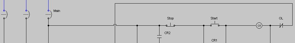
11 Control circuits associated with motor controls can be complex and vary greatly with application. Elements of a control circuit include: Conductors and raceways Contactor operating coil Source of energy supply to the circuit Overcurrent protection devices All switching devices that govern energization of the operating coil. Where one side of the motor control circuit is grounded, the control circuit must prevent the motor from being started due to a ground fault in the control circuit wiring. WRONGLY DESIGNED CONTROL CIRCUIT If one side of the start button is in the ground leg of the circuit, as shown, a ground fault on the coil side of the start button can short circuit the start circuit and start the motor. 11


12 Simulated Wrongly Designed Control Circuit CORRECTLY DESIGNED CONTROL CIRCUIT By switching the hot leg, as shown, the starting of the motor due to an accidental ground fault can be effectively eliminated. 12


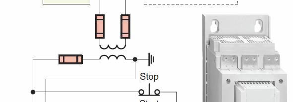
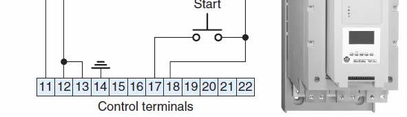
13 Simulated Correctly Designed Control Circuit Where a transformer is used to obtain a reduced voltage for the motor control circuit and the transformer is located within the motor controller enclosure, the transformer must be connected to the load side of the motor control circuit disconnecting means. The control transformer must be protected in accordance with NEC Article (C) 13


14 FULL VOLTAGE STARTING OF AC INDUCTION MOTORS A full voltage, or across-the-line, starter is designed to apply full line voltage to the motor upon starting. Uses an ON/OFF snapaction switch with overload protection. When started the motor is connected directly across the line and in series with the starter contact and overload device. Fractional horsepower manual across-the-line starter When an overload is sensed, the starter contacts open and cannot be reclosed until the overload relay is reset manually. 14


15 Double-pole manual motor starter with a single overload heater to protect the motor windings. Line rated control devices such as thermostats, float switches and relays are used to connect and disconnect the motor when automatic operation is desired. A three-pole manual starter provides three overload heaters to protect the motor windings. This starter is operated by pushing a button on the starter enclosure cover that mechanically operates the starter. When an overload relay trips, the starter mechanism unlatches, opening the contacts to stop the motor. The contacts cannot be reclosed until the starter mechanism has been reset by pressing the STOP button; first, however, the thermal unit needs time to cool. 15


.")


16 The power circuit contacts of manual motor starters are unaffected by the loss of voltage, so consequently will remain closed when the supply voltage fails. Operating Mechanism If the supply voltage fails, the motor will stop and restart automatically when the supply voltage is restored (no voltage release). Manual starters must be mounted near the motor that is being controlled. Remote control operation is not possible as it would be with a magnetic starter. The magnetic starter contacts are closed by energizing a holding coil. This enables the use of automatic and remote control of the motor. Pushbutton stations are mounted nearby, but automatic control pilot devices can be mounted almost anywhere on the machine. 16


17 Three-phase magnetic across the line AC starter Additional stop and start connections Simulated Two Start/Stop Magnetic Starter 17

18 Circuit used to start two motors at full line voltage. Power and control circuit wiring Circuit used to start two motors at full line voltage. The first motor is started by pressing the start button connected in a three-wire control configuration to motor starter M1. Power is applied to both Motor 1 and on-delay timer coil TR. After the preset time, normally open timer contacts TR close to energize starter coil M2 and the second motor starts. Both motors will stop by pressing the stop button. 18


19 Simulated two motor starting circuit. REDUCED VOLTAGE STARTING OF INDUCTION MOTORS 19


20 Reduced voltage starters limit line voltage disturbances and lower excessive starting torque The large starting in-rush current of a large size motor could cause line voltage dips and brownouts. In addition to high starting currents, the motor also produces starting torques that are higher than full-load torque. In many applications this starting torque can cause excessive mechanical, damage such as belt, chain, or coupling breakage. When a reduced voltage is applied to motor at rest, both the current drawn by the motor and the torque produced by the motor are reduced. Reduced voltage is obtained in the primary resistance starter by means of resistances that are connected in series with each motor stator lead during the starting period. The voltage drop in the resistors produces a reduced voltage at the motor terminals. After a preset time period the R contacts close to short circuit the starting resistors and apply full line voltage to the motor. 20


21 Pressing the start button energizes motor starter coil M and timer coil TR. The motor is then started through a resistor in each of the three incoming lines. After the preset time has elapsed the timer contacts close to energize contactor C coil. This causes contacts C to close shorting out the starting resistor bank and applying full voltage to the motor. Simulated primary resistance starting circuit. 21


22 The autotransformer starter uses a step-down autotransformer to reduce the line voltage. Multiple taps on the transformer permit the voltage, current, and torque to be adjusted to satisfy many different starting conditions. In closed transition starting, the motor is never disconnected from the line source during acceleration. On starting timer coil TR and contactor coils C2 and C3 are energized. Main contacts C2 and C3 close and the motor is connected through the transformers taps to the power line. After the starting period has elapsed TR timed contacts operate to deenergize contactors C2 and C3 and energize contactor C1, resulting in the connection of the motor to full line voltage. 22

23 The Wye-Delta starter connects the motor windings first in Wye during the starting period and then in Delta after the motor has accelerated. Wye-delta starters can only be used with three-phase AC motors where all six leads of the stator windings are available. When wye connected the motor starts with a significantly lower current than when delta connected. On starting coils S, M1 and TR are energized connecting the motor winding in a wye configuration After the time delay period has elapsed, the TR contacts change state to de-energize contactor coil S and energize contactor coil M2. The motor then continues to run with the motor connected in a delta arrangement. 23


 Start and")


24 Simulated Wye-Delta Starter Part-winding starters are used on induction motors wound for dual voltage operation (e.g. 230/460 V) Start and Run Power is applied to part of the motor windings on startup and then connects the remaining coils for normal speed. Run only 24


25 These motors have two sets of windings connected in parallel for low-voltage operation and in series for high-voltage operation. When used on the lower voltage, they can be started by first energizing only one winding, limiting starting current and torque to approximately one-half of the full voltage values. 230/460 V motor 230 V The second winding is then connected in parallel, once the motor nears operating speed. Since one set of windings has higher impedance than the two connected in parallel, less inrush current flows to the motor on startup. On starting coils M1 and TR1 are energized. M1 contacts close immediately starting the motor at reduced current and torque through one-half of the wye windings. After the preset time has elapsed the timer contacts close to energize starter coil M2 applying voltage to the second set of wye windings. 25
 to the proper terminals on")


 the voltage")
26 It is of utmost importance to connect the motor terminals (T1, T2, T3, T7, T8 and T9) to the proper terminals on the motor starter. When motor winding T7- T8- T9 is connected, it must produce the same rotation. If by chance an error has been made, and T8 and T9 were interchanged, the second winding will attempt to change the rotation of the motor. Extremely high current will then flow, damaging the equipment. Electronic soft-starters limit motor starting current and torque by ramping (gradually increasing) the voltage applied to the motor during the selected staring time. Current limit is used when it is necessary to limit the maximum starting current and is usually adjustable. 26

27 Typical soft starter connections. DC MOTOR STARTING 27


28 One major difference between AC and DC starters are the electrical and mechanical requirements necessary for suppressing the arcs created in opening and closing contacts under load. To combat prolonged arcing in DC circuits, the contactor switching mechanism is constructed so that the contacts will separate rapidly and with enough air gap to extinguish the arc as soon as possible on opening. Across-the-line DC motor starter To help extinguish the arc, the starter is equipped with three power contacts connected in series. 28


29 Definite-time reduced voltage DC motor starter. When the M contact closes, full line voltage is applied to the shunt field while the resistor is connected in series with the armature. Following a preset time period, the contactor R closes, bypassing the resistor, allowing the motor to operate at base speed. This gives the motor smooth torque without creating a large surge of current. Variable voltage acceleration of a DC shunt motor can be obtained by using an SCR (Silicon Controlled Rectifier) armature voltage controller. AC Source Load Current An SCR is a semiconductor device that has three elements: anode, cathode, and gate. The SCR provides a useful method of converting AC voltage to variable DC voltage. 29
30 By applying a signal to the gate element at precisely the right time, you can control how much current the SCR will either pass or block during a cycle. This is known as phase control. The shorter the on time, the lower the DC voltage applied to the armature. REVERSING OF AC INDUCTION MOTORS 30
31 REVERSING THREE-PHASE INDUCTION MOTOR STARTER Interchanging any two leads to a three-phase induction motor will cause it to run in the reverse direction. The industry standard is to interchange phase A (Line 1) and phase C (Line 3), while phase B (Line 2) remains the same. 31


32 Reversing starters are used to automatically accomplish phase reversal. NEMA Type Forward Contactor Reverse Contactor IEC Type OL Relay Stop FWD/REV Power circuit of a magnetic full voltage three-phase reversing motor starter Uses two three-pole contactors with a single overload relay assembly. The power circuits of the two contactors are interconnected. t Contacts F connect L1, L2, and L3 to motor terminals T1, T2, and T3, respectively. Contacts R connect L1 to motor terminal T3 and connect L3 to motor terminal T1, causing the motor to reverse direction. 32
33 When reversing the motor, it is vital that the forward and reverse contactors not be energized at the same time. Activating both contactors would cause a short circuit since two of the line conductors are reversed on one contactor. Both mechanical and electrical interlocks are used to prevent the forward and reverse contactors from being activated at the same time. Mechanical interlocking uses a system of levers to prevent both contactors from being engaged at the same time. The broken line indicates that the coils F and R cannot close contacts simultaneously because of the mechanical interlocking action of the device. 33


34 Simulated Reversing Starter With No Interlocking Mechanical interlocks have been known to fail and for this reason additional electrical interlocking is used for added protection. Most reversing starters utilize auxiliary contacts operated by the forward and reverse coils to provide electrical interlocking. 34


35 The NC contact controlled by the forward coil is connected in series with the reverse coil. The NC contact controlled by the reverse coil is connected in series with the forward coil. When the R coil is energized, the NC contact in series with the F coil is opened to prevent the F coil from being energized. When the F coil is energized, the NC contact in series with the R coil is opened to prevent the R coil from being energized Simulated Auxiliary Contact Interlocking 35

36 Electrical pushbutton interlocking utilizes break-make, normally closed and normally open switch contacts on the forward and reverse buttons. Interlocking is achieved by connecting the NC contact of the reverse button in series with the NO contact of the forward button and vise versa. The NC contact of the reverse button acts like another stop button in the forward circuit. The NO contact on the reverse button is used as the start button for the reverse circuit. The motor reverses direction immediately without the stop button being pressed. When the reverse button is pressed, its NC contact opens the circuit to the forward coil and at the same time its NC contact completes the circuit to the reverse coil. 36


37 Simulated Pushbutton Interlocking Limit switches can be incorporated into a reversing starter circuit to limit travel. The location of the limit switches allows the direction of travel to be stopped if the motor is driving a device that has limits to its travel. 37


38 Simulated Travel Limit Switch Operation Single-Phase Motor Reversing Direction of rotation is changed by interchanging the start winding leads, while those of the run winding remain the same. The centrifugal switch must be allowed to reclose before any attempt to reverse the direction of rotation 38
 has two sets of contacts, one normally open and the other normally closed.")


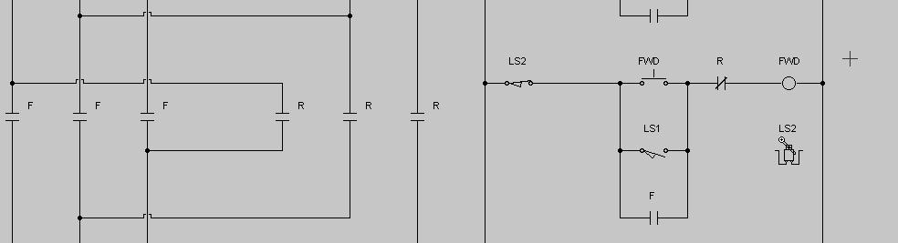
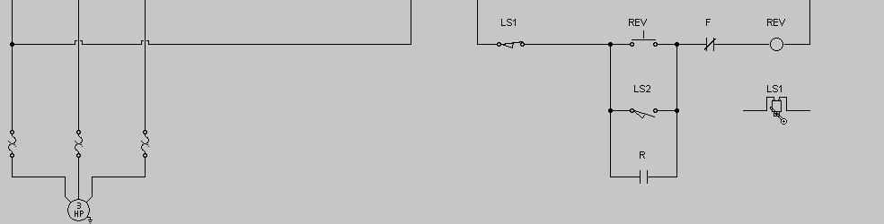
39 Some reciprocating machine process use two limit switches to provide automatic control of the motor. Each limit switch (LS1 and LS2) has two sets of contacts, one normally open and the other normally closed. Start/Stop buttons are used to initiate and terminate the automatic control. The NC contact of LS2 acts as the stop for the FWD controller, and the NO contact t of LS1 acts as the start contact for the FWD controller. The NC contact of LS1 is wired as a stop contact for the REV controller, and the NO contact of LS2 is wired as a start contact for the REV controller. FWD/REV buttons provide a means of starting the motor in order that the limit switches can take over automatic control. 39
40 Simulated Reciprocating Machine Process REVERSING OF DC MOTORS 40
41 A DC motor is reversed by: Reversing the direction of the armature current and leaving the field current the same. Reversing the direction of the field current and leaving the armature current the same. Most are reversed by switching the direction of current flow through the armature. Since the armature has a much lower inductance than the field less arcing occurs at the contacts when reversed in this manner. For electronic control, two sets of SCRs are provided. One set is used for current flow in one direction through the armature, and the second set is used for current flow in the opposite direction. 41

42 JOGGING Jogging is the momentary operation of a motor for the purpose of accomplishing small movements of the driven machine. Jogging is used for frequent starting and stopping of a motor for short periods of time. It involves an operation in which the motor runs when the button is pressed and will stop when the button is released. 42
43 Pushbutton Jog Circuit With the M coil deenergized and the jog button then pressed, a circuit is completed for the M coil around the M maintaining contact. The M main contacts close to start the motor, but the maintaining circuit is incomplete as the NC jog contact is open. As a result, starter coil M will not seal in; instead, it can stay energized only as long as the jog button is fully depressed. On quick release of the jog push button, should its NC contacts reclose before the starter maintaining contact M opens, the motor would continue to run. In certain applications this could be hazardous to workers and machinery. 43

44 Simulated Pushbutton Jog Circuit A control relay jogging circuit is much safer method of implementing jog control. Pressing the start button energizes coils CR and M to start and run the motor. Pressing the jog button energizes the M coil only, starting the motor. Both CR contacts remain open, and the CR coil is deenergized. The M coil will not remain energized when the jog push button is released. 44


45 Simulated Control Relay Jog Circuit A selector switch connected in the control circuit can also be used to implement jogging. The start button doubles as a jog button. When the selector switch is placed in the run position, the maintaining circuit is not broken. If the start button is pressed, the M coil circuit is completed and maintained. Turning the selector switch to the jog position opens the maintaining circuit. Pressing the start button completes the circuit for the M coil, but the maintaining circuit is open. 45


46 Simulated Selector Switch Jog Circuit The most common method of stopping a motor is to remove the supply voltage and allow the motor and load to coast to a stop. In some applications, however, the motor must be stopped more quickly or held in position by some sort of braking device. 46

47 PLUGGING AND ANTI-PLUGGING Plugging stops a polyphase motor quickly, by momentarily connecting the motor for reverse rotation while the motor is still running in the forward direction. Plugging acts as a retarding force for rapid stop and quick reversal of motor rotation. 47


48 Plugging produces more heat than most normal-duty applications. NEMA specifications i call for reversing starters used for such applications to be derated. The next size larger reversing starter must be selected when it is used for plugging to stop or reverse at a rate of more than five times per minute. A zero-speed or plugging switch wired into the control circuit of a standard reversing starter can be used for automatic plugging of a motor. The zero-speed switch is coupled to a moving shaft on the machinery whose motor is to be plugged. The switch prevents the motor from reversing after it has come to a stop. As the zero-speed switch rotates, centrifugal force or a magnetic clutch causes its contacts to open or close. 48


49 Forward direction plugging control circuit. Reversing Starter Zero-Speed or Plugging Switch With the motor operating pressing the stop button deenergizes the forward contactor. The reverse contactor is energized, and the motor is plugged. The motor speed decreases at which point its forward contact opens and deenergizes the reverse contactor. 49


50 The sudden reversing torque applied when a large motor is reversed (without slowing the motor speed) could damage the driven machinery, and the extremely high current could affect the distribution ib ti system. Antiplugging protection is obtained when a device prevents the application of a counter torque until the motor speed is reduced to an acceptable value. Antiplugging circuit used to prevent reversing the motor before the motor has slowed to near zero speed. Pressing the forward button completes the circuit for the F coil, closing the F power contacts and causing the motor to run in the forward rotation. The F zero-speed switch contact opens because of the forward rotation of the motor. 50


51 Pressing the stop button deenergizes the F coil, which opens the F power contacts, causing the motor to slow down. Pressing the reverse button will not complete a circuit for the R coil until the F zero-speed switch contact recloses. As a result, when the rotating equipment reaches near zero speed, the reverse circuit may be energized, and the motor will run in the reverse rotation. Simulated Anti-Plugging Protection Circuit 51

52 DYNAMIC BRAKING Dynamic braking is achieved by reconnecting a running motor to act as a generator immediately after it is turned off, rapidly stopping the motor. The generator action converts the mechanical energy of rotation to electrical energy that can be dissipated as heat in a resistor. Dynamic Braking Resistor The smaller the ohmic value of the braking resistor, the greater the rate at which energy is dissipated and the faster the motor comes to rest. 52


53 Dynamic braking of a DC motor may be needed because DC motors are often used for lifting and moving heavy loads that may be difficult to stop. Assume the motor is operating and the stop button is pressed. Starter coil M deenergizes to open the normally open M power contact to the motor armature. At the same time, the normally closed M power contact closes to complete a braking circuit around the armature through the braking resistor, which acts like a load. The shunt field winding of the DC motor remains connected to the power supply. The armature generates a counter emf voltage. This counter emf causes current to flow through the resistor and armature. 53

54 Simulated Dynamic Braking Circuit DC INJECTION BRAKING 54


55 DC injection braking is a method of braking in which direct current is applied to the stationary windings of an AC motor after the applied AC voltage is removed. The injected DC voltage creates a magnetic field in the motor stator winding that does not change in polarity. In turn, this constant magnetic field in the stator creates a magnetic field in the rotor. Because the magnetic field of the stator is not changing in polarity, it will attempt to stop the rotor when the magnetic fields are aligned (N to S and S to N). DC injection braking applied to a three-phase AC induction motor. 55
56 Trans Rectifier A transformer with tapped windings is used to adjust the amount of braking torque applied to the motor. The DC injection voltage is obtained from the full-wave bridge rectifier circuit, which changes the line voltage from AC to DC. Coils M and B are interlocked so that the AC and DC supplies are not connected to the motor at the same time. Pressing the start button energizes starter coil M and offdelay timer coil TR. Off-delay timer contact TR remains closed at all times while the motor is operating. M1 contact closes to maintain current to the starter coil and M2 contact opens to open the current path to braking coil B. When the stop button is pressed, starter coil M and off- delay timer coil TR are deenergized. Braking coil B becomes energized through the closed TR contact. All B contacts close to apply DC braking power to the motor stator winding. Coil B is deenergized after the timer contact time out. 56


57 Simulated DC Injection Braking Circuit ELECTROMECHANICAL FRICTION BRAKES 57


58 Electromechanical friction brakes can hold the motor shaft stationary after the motor has stopped. Drum and shoe-type friction brake used on DC series motor drives. The brake drum is attached to the motor shaft and the brake shoes are used to hold the drum in place. The brake is set with a spring and released by a solenoid. When the motor is running, the solenoid is energized to overcome the tension of the spring, thus keeping the brake shoes clear of the drum. When the motor is turned off, the solenoid is deenergized and the brake shoes are applied to the drum through the spring tension. The brake operating coil is connected in series with the motor armature and release and sets in response to motor current. This type of braking is fail-safe in that the brake is applied in case of an electrical failure. 58

59 AC motor electromagnetic brakes are commonly used as parking brakes to hold a load in place or as stopping brakes to decelerate a load. These motors are directly coupled to an AC electromagnetic brake. When the power source is turned off, the motor stops instantaneously and holds the load. Most come equipped with an external manual release device, which allows the driven load to be moved without energizing the motor. MULTISPEED MOTORS 59


60 The speed of an induction motor depends on the number of poles built into the motor and the frequency of the electrical power supply. A single-speed motor has one rated speed at which it runs when supplied with the nameplate voltage and frequency. A multispeed motor will run at more than one speed, depending on how you connect it to the supply. Multispeed motors typically have two speeds to choose from, but they may have more. The different speeds of a multispeed motor are selected by connecting the external motor winding stator leads to a multispeed starter. Multispeed magnetic starters automatically reconnect multispeed motor windings for the desired speed in response to a signal received from push button stations or other pilot devices. 60
61 Multispeed motors are available in two basic versions: consequent pole and separate winding. A separate winding motor has a winding for each speed. High Speed Winding Low Speed Winding The speed of each winding depends on the number of poles. The low-speed winding is wound for more poles than the high-speed winding. The motor cost is higher than consequent pole, but the control is simpler. A consequent pole motor has a winding for every two speeds. Taps are brought from the winding for reconnection for a different number of poles. Two-speed, consequent-pole motors have one reconnectable winding. Low speed of a two speed, consequent-pole motor is one half the speed of high speed. Three-speed motors have one reconnectable winding and one fixed winding. 61

62 Two-speed separate winding starter. Contains a high-speed and a low-speed starter, mechanically and electrically interlocked with each other. Requires two sets of overload relays, one for the highspeed circuit and one for the low-speed circuit. Control panel contains high-speed button, low-speed push, off/high/low selector switch, high-speed OL reset, and low-speed OL reset. WOUND ROTOR MOTORS 62


 connects the primary circuit to the line, and two secondary accelerating contactors (S and")

63 A wound rotor motor is constructed with rotor windings that are brought out of the motor through slip rings on the motor shaft. These windings are connected to a controller, which places variable resistors in series with the windings. By changing the amount of external resistance connected to the rotor circuit, the motor speed can be varied. Power circuit for a wound-rotor magnetic motor controller. A magnetic starter (M) connects the primary circuit to the line, and two secondary accelerating contactors (S and H), control the speed. When operating at low speed, contactors S and H are both open, and full resistance is inserted in the rotor s secondary circuit. When contactor S closes, it shunts out part of the total resistance in the rotor circuit; as a result, the speed increases. When contactor H closes, all resistance in the secondary circuit of the motor is bypassed; thus, the motor runs at maximum speed. 63


64 One disadvantage of using resistance to control the speed of a wound-rotor induction motor is that a lot of heat is dissipated in the resistors; the efficiency, therefore, is low. Speed regulation is also poor when using resistance to control speed; for a given amount of resistance, the speed varies considerably if the mechanical load varies. Modern wound-rotor controllers use solid-state devices to obtain stepless control. ol These may incorporate thyristors (semiconductors) that serve in the place of magnetic contactors. Chapter 8 64
Jogging and Plugging of AC and DC Motors. Prepared by Engr. John Paul Timola, LPT
 Jogging and Plugging of AC and DC Motors Prepared by Engr. John Paul Timola, LPT Jogging sometimes called inching momentary operation of a motor for the purpose of accomplishing small movements of the
ECET 211 Electric Machines & Controls Lecture 8 Motor Control Circuits (1 of 2) Lecture 8 Motor Control Circuits
 Lecture 8 Motor Control Circuits") ECET 211 Electric Machines & Controls Lecture 8 Motor Control Circuits (1 of 2) Text Book: Electric Motors and Control Systems, by Frank D. Petruzella, published by McGraw Hill, 2015. Paul I-Hai Lin, Professor
ECET 211 Electric Machines & Controls Lecture 8 Motor Control Circuits (1 of 2) Text Book: Electric Motors and Control Systems, by Frank D. Petruzella, published by McGraw Hill, 2015. Paul I-Hai Lin, Professor
Electrical Motor Controls (Fourth Edition)
") Electrical Motor Controls (Fourth Edition) 1. Which drawing type shows physical details as seen by the eye? Pictorial Drawing 2. Which drawing is similar to a pictorial drawing but has circles or rectangles
Electrical Motor Controls (Fourth Edition) 1. Which drawing type shows physical details as seen by the eye? Pictorial Drawing 2. Which drawing is similar to a pictorial drawing but has circles or rectangles
Electrical Motor Controls Chapter 4 (Fourth Edition) Chapter 2 (Fifth Edition)
 Chapter 2 (Fifth Edition)") Electrical Motor Controls Chapter 4 (Fourth Edition) Chapter 2 (Fifth Edition) 1. Which drawing type shows physical details as seen by the eye? 2. Which drawing is similar to a pictorial drawing but has
Electrical Motor Controls Chapter 4 (Fourth Edition) Chapter 2 (Fifth Edition) 1. Which drawing type shows physical details as seen by the eye? 2. Which drawing is similar to a pictorial drawing but has
Types of Motor Starters There are several types of motor starters. However, the two most basic types of these electrical devices are:
 Introduction Motor starters are one of the major inventions for motor control applications. As the name suggests, a starter is an electrical device which controls the electrical power for starting a motor.
MOTOR TERMINAL CONNECTIONS
 MOTOR TERMINAL CONNECTIONS Motor Classification Most of the industrial machines in use today are driven by electric motors Motors are classified according to the type of power used (AC or DC) and the motors
MAGNETIC MOTOR STARTERS
 Chapter 6 MAGNETIC MOTOR STARTERS 1 The basic use for the magnetic contactor is for switching power in resistance heating elements, lighting, magnetic brakes, or heavy industrial solenoids. Contactors
ECET 211 Electric Machines & Controls Lecture 8 Motor Control Circuits (2 of 2) Lecture 8 Motor Control Circuits
 Lecture 8 Motor Control Circuits") ECET 211 Electric Machines & Controls Lecture 8 Motor Control Circuits (2 of 2) Text Book: Electric Motors and Control Systems, by Frank D. Petruzella, published by McGraw Hill, 2015. Paul I-Hai Lin, Professor
ECET 211 Electric Machines & Controls Lecture 8 Motor Control Circuits (2 of 2) Text Book: Electric Motors and Control Systems, by Frank D. Petruzella, published by McGraw Hill, 2015. Paul I-Hai Lin, Professor
Programmable Logic Controller. Mat Nor Mohamad
 Programmable Logic Controller Mat Nor Mohamad Relays Electromagnetic Control Relays The PLC's original purpose was the replacement of electromagnetic relays with a solid-state switching system that could
Electric Motor Controls BOMA Pre-Quiz
 Electric Motor Controls BOMA Pre-Quiz Name: 1. How does a U.P.S. (uninterruptable power supply) work? A. AC rectified to DC batteries then inverted to AC B. Batteries generate DC power C. Generator, batteries,
Module 2 CONTROL SYSTEM COMPONENTS. Lecture - 4 RELAYS
 1 Module 2 CONTROL SYSTEM COMPONENTS Lecture - 4 RELAYS Shameer A Koya Introduction Relays are generally used to accept information from some form of sensing device and convert it into proper power level,
MOTOR CONTROLLERS. STATE the function of motor controllers.
 Electrical Distribution Systems Motor controllers range from a simple toggle switch to a complex system using solenoids, relays, and timers. The basic functions of a motor controller are to control and
SALDET SALES & SERVICE, INC. CLINTON TOWNSHIP, MICHIGAN
 Form 1254 BRAKETRON Electronic Motor Brake Instructions SALDET SALES & SERVICE, INC. CLINTON TOWNSHIP, MICHIGAN TABLE OF CONTENTS SECTION TITLE PAGE I. Introduction 1 II. Specifications 1 III. Principles
Industrial Automation Commonly-Used Terms
 Industrial Automation Commonly-Used Terms A Glossary of Industrial Automation and Control Terms LECINC.COM 1 A Accelerating Time: Across the Line Starter: Action Device: Actuator: Air (used as prefix):
SECTION MOTOR CONTROL
 SECTION 26 24 19 MOTOR CONTROL PART 1 - GENERAL 1.1 SECTION INCLUDES A. Manual motor starters B. Magnetic motor starters C. Combination magnetic motor starters D. Solid-state reduced voltage motor starters
EE6351 ELECTRIC DRIVES AND CONTROL UNIT-1 INTRODUTION
 EE6351 ELECTRIC DRIVES AND CONTROL UNIT-1 INTRODUTION 1. What is meant by drive and electric drive? Machines employed for motion control are called drives and may employ any one of the prime movers for
9/7/2010. Chapter , The McGraw-Hill Companies, Inc. MOTOR CLASSIFICATION. 2010, The McGraw-Hill Companies, Inc.
 Chapter 2 MOTOR CLASSIFICATION 1 In general, motors are classified according to the type of power used (AC or DC) and the motor's principle of operation. AC DC Motor Family Tree 2 DC MOTOR CONNECTIONS
Open & enclosed. Spec Tech Industrial 203 Vest Ave. Valley Park, MO Phone: 888 SPECTECH. Reduced voltage starters. Overload relay protection
 Reduced voltage starters Open & enclosed Reduced voltage starters Description Compact, space saving design 8 starter frame sizes, A16 to A750 Maximum U.L. horsepower ratings Mechanically interlocking as
Starting of Induction Motors
 1- Star Delta Starter The method achieved low starting current by first connecting the stator winding in star configuration, and then after the motor reaches a certain speed, throw switch changes the winding
ROTATING MAGNETIC FIELD
 Chapter 5 ROTATING MAGNETIC FIELD 1 A rotating magnetic field is the key to the operation of AC motors. The magnetic field of the stator is made to rotate electrically around and around in a circle. Stator
Full Voltage Starting (Number of Starts):
:") Starting Method Full Voltage Starting (Number of Starts): Squirrel cage induction motors are designed to accelerate a NEMA inertia along a NEMA load curve with rated voltage applied to the motor terminals.
Starting Method Full Voltage Starting (Number of Starts): Squirrel cage induction motors are designed to accelerate a NEMA inertia along a NEMA load curve with rated voltage applied to the motor terminals.
MOTOR TERMINAL CONNECTIONS
 MOTOR TERMINAL CONNECTIONS Motor Classification Most of the industrial machines in use today are driven by electric motors Motors are classified according to the type of power used (AC or DC) and the motors
Application Description
 -14 Type, Intelligent Technologies (IT.) Soft Starters February 2007 Contents Description Page Type, Intelligent Technologies (IT.) Soft Starters Product Description....... -14 Application Description....
lectronic starter for single phase duction motor
 lectronic starter for single phase duction motor PROJECT NO: 104 SUPERVISOR: DR. WEKESA EXAMINER: PROF MANG OLI Prepared by: GITONGA HILDA WANJIKU- F17/39921/2011 PROJECT OUTLINE 1. Project Objective 2.
SHORT-STOP. Electronic Motor Brake Type G. Instructions and Setup Manual
 Electronic Motor Brake Type G Instructions and Setup Manual Table of Contents Table of Contents Electronic Motor Brake Type G... 1 1. INTRODUCTION... 2 2. DESCRIPTION AND APPLICATIONS... 2 3. SAFETY NOTES...
2006 MINI Cooper S GENINFO Starting - Overview - MINI
 MINI STARTING SYSTEM * PLEASE READ THIS FIRST * 2002-07 GENINFO Starting - Overview - MINI For information on starter removal and installation, see the following articles. For Cooper, see STARTER WITH
Direct On Line (DOL) Motor Starter. Direct Online Motor Starter
 Motor Starter. Direct Online Motor Starter") Direct On Line (DOL) Motor Starter Direct Online Motor Starter Different starting methods are employed for starting induction motors because Induction Motor draws more starting current during starting.
Direct On Line (DOL) Motor Starter Direct Online Motor Starter Different starting methods are employed for starting induction motors because Induction Motor draws more starting current during starting.
Desensitizing Electric Motor Controls
 Pacific Gas and Electric Company Desensitizing Electric Motor Controls Introduction. This note is not meant to be a complete discussion of this topic; it is only an attempt to explain some basic operating
Basics of Control Components
 Basics of Control Components Table of Contents Introduction...2 Electrical Symbols...6 Line Diagrams...16 Overload Protection...22 Overload Relays...26 Manual Control...35 Magnetic Contactors and Starters...41
Electrical Drives I. Week 11: Three phase Induction Motor Starting
 Electrical Drives I Week 11: Three phase Induction otor Starting Starting Problem Definition: ' I r Rs Vs 2 R ' r S 2 Xeq At S=0 and S=1, thus the current can be determined as: ' I r st Vs 2 ' Rs Rr Xeq
Application Note CTAN #127
 Application Note CTAN #127 Guidelines and Considerations for Common Bus Connection of AC Drives An important advantage of AC drives with a fixed DC is the ability to connect the es together so that energy
Motor Starters. Reduced Voltage. Reduced Voltage Motor Starters 1. Contents
 1 January 00 Reduced Voltage Motor Starters Contents Description Page Open Type S7, Intelligent Technologies (IT.) Soft Starters Product Description............................................. Application
THE BEST ELECTRICAL CONTROLS BUSINESS ON THE PLANET! Unmatched Service Superior Product Quality Advantage Pricing
 Introduction A contactor is an electrical device which is used for switching an electrical circuit on or off. It is considered to be a special type of relay. However, the basic difference between the relay
Horizontal Circuit Switchers
 > Transformer Protection > CIRCUIT SWITCHERS C A T A L O G B U L L E T I N General Application Southern States Types CSH and CSH-B Horizontal Circuit Switchers provide an economical, versatile, space saving
MANUAL ELECTRIC FIRE PUMP CONTROLLERS METRON SERIES M450
 MANUAL ELECTRIC FIRE PUMP CONTROLLERS METRON SERIES M450 TABLE OF CONTENTS PART I GENERAL DESCRIPTION... PAGE 2 PART II FUNCTIONS... PAGE 2 PART III INSTALLATION... PAGE 3 PART IV INITIAL INSTALLATION
SECTION 4 ELECTRIC MOTORS UNIT 17: TYPES OF ELECTRIC MOTORS UNIT OBJECTIVES UNIT OBJECTIVES 3/21/2012
 SECTION 4 ELECTRIC MOTORS UNIT 17: TYPES OF ELECTRIC MOTORS UNIT OBJECTIVES After studying this unit, the reader should be able to Describe the different types of open single-phase motors used to drive
Horizontal Circuit Switchers
 > Transformer Protection > CIRCUIT SWITCHERS C A T A L O G B U L L E T I N General Application Southern States Types CSH and CSH-B Horizontal Circuit Switchers provide an economical, versatile, space saving
ECET 211 Electric Machines & Controls Lecture 6 Contactors and Motor Starters. Lecture 6 Contactors and Motor Starters
 ECET 211 Electric Machines & Controls Lecture 6 Contactors and Motor Starters Text Book: Chapter 6, Electric Motors and Control Systems, by Frank D. Petruzella, published by McGraw Hill, 2015. Paul I-Hai
Installation and Maintenance Instructions. World Leader in Modular Torque Limiters. PTM-4 Load Monitor
 World Leader in Modular Torque Limiters Installation and Maintenance Instructions PTM-4 Load Monitor 1304 Twin Oaks Street Wichita Falls, Texas 76302 (940) 723-7800 Fax: (940) 723-7888 E-mail: sales@brunelcorp.com
2.1 Warnings & Agency Approvals Electrical Connections - Specifications Standard Wiring Configurations...2 4
 CHAPTER ELECTRICAL 2 INSTALLATION Contents of this Chapter... 2.1 Warnings & Agency Approvals..................2 2 2.1.1 Isolation..............................................2 2 2.1.2 Electrical Power
SECTION MOTOR CONTROLLERS
 PART 1 - GENERAL 1.1 DESCRIPTION SECTION 26 29 11 SPEC WRITER NOTE: Use this section only for NCA projects. Delete between // ---- // if not applicable to project. Also, delete any other item or paragraph
STEP Motor Control Centers
 STEP 2000 Motor Control Centers Table of Contents Introduction...2 Motor Control...4 Power Supplies...8 Design Standards...13 Need for Circuit Protection...14 Overcurrent-Protection Devices...19 Motor
300% Motor full load amps at 80 seconds, 400% Motor full load amps at 35 seconds
 Digital Soft Start Controls Soft Starters & 9 thru 900 s 208-460V 50/60 Hz. 9 thru 900 s 208-575V 50/60 Hz. Farm Duty Applications: Controlled ramp start and stop, minimize spillage in material handling,
DHANALAKSHMI COLLEGE OF ENGINEERING DEPARTMENT OF MECHANICAL ENGINEERING ME 6351 ELECTRICAL DRIVES AND CONTROL UNIVERSITY QUESTIONS AND ANSWERS
 DHANALAKSHMI COLLEGE OF ENGINEERING DEPARTMENT OF MECHANICAL ENGINEERING ME 6351 ELECTRICAL DRIVES AND CONTROL UNIVERSITY QUESTIONS AND ANSWERS 1) What is the Necessity of starter? UNIT 3 Two Marks Both
Adapted from presentation developed by Scott Fausneaucht
 Adapted from presentation developed by Scott Fausneaucht Definition of Electricity Electrical Fundamentals Generation & Transmission Transformers Fuses & Circuit Breakers Motors Motor Controls Safety Not
ECET Circuit Design Motor Loads. Branch Circuits. Article 210
 ECET 4520 Industrial Distribution Systems, Illumination, and the NEC Circuit Design Motor Loads Branch Circuits Article 210 210.1 Scope This article covers branch circuits except for those that supply
EXPERIMENT 2 THREE PHASE INDUCTION MOTOR, PART 1
 University f Jordan School of Engineering Department of Mechatronics Engineering Electrical Machines Lab Eng. Osama Fuad Eng. Nazmi Ashour EXPERIMENT 2 THREE PHASE INDUCTION MOTOR, PART 1 OBJECTIVES To
SECTION MOTORS, MOTOR STARTERS, VARIABLE FREQUENCY DRIVES AND ELECTRICAL WORK
 PART 1 - GENERAL 1.1 GENERAL: SECTION 15150 MOTORS, MOTOR STARTERS, VARIABLE FREQUENCY DRIVES AND ELECTRICAL WORK A. The Mechanical Contractor shall furnish to the Electrical Contractor for installation,
team master medium voltage solid state starters
 team master medium voltage solid state starters The Today s global economy is in many ways driven by the AC Induction Motor. Industrial facilities worldwide depend on these motors to drive the machinery
AIR COOLED RECTIFIER SPECIFICATION S-50-A
 SPECIFICATIONS AIR COOLED RECTIFIER Spec50a1 5JAN1999 SPECIFICATION S-50-A HIGH VOLTAGE SINGLE TRANSFORMER AIR COOLED RECTIFIER Standard output power range: 250 to 600 volts at 100 to 1,200 amperes TECHNICAL
3.0 CHARACTERISTICS E Type CO-4 Step-Time Overcurrent Relay
 41-106E Type CO-4 Step-Time Overcurrent Relay A core screw accessible from the top of the switch provides the adjustable pickup range. The IIT contacts are connected in the trip circuit to trip instantaneously.
A. Products shall be designed, manufactured, tested, and installed in compliance with the following standards:
 SECTION 26 29 13 ENCLOSED MOTOR CONTROLLERS PART 1 - GENERAL 1.1 RELATED DOCUMENTS: A. The Conditions of the Contract and applicable requirements of Divisions 0 and 1 and Section 26 00 01, Electrical General
Motor Protection. Voltage Unbalance & Single-Phasing
 For Summary of Suggestions to Protect Three-Phase Motors Against Single-Phasing see the end of this section, page 137. Historically, the causes of motor failure can be attributed to: Overloads 30% Contaminants
Pretest Module 21 Units 1-4 AC Generators & Three-Phase Motors
 Pretest Module 21 Units 1-4 AC Generators & Three-Phase Motors 1. What are the two main parts of a three-phase motor? Stator and Rotor 2. Which part of a three-phase squirrel-cage induction motor is a
ABB. Type CRQ Directional Negative Sequence Relay for Ground Protection B 1.0 APPLICATION 2.0 CONSTRUCTION AND OPERATION CAUTION
 ABB Instruction Leaflet 41-163.2B Effective: January 1977 Supersedes I.L. 41-137.3A, Dated September 1974 ( ) Denotes Change Since Previous Issue Type CRQ Directional Negative Sequence Relay for Ground
ECET 211 Electric Machines & Controls Lecture 4-1 Motor Control Devices: Lecture 4 Motor Control Devices
 ECET 211 Electric Machines & Controls Lecture 4-1 Motor Control Devices: Part 1. Manually Operated Switch Part 2. Mechanically Operated Switch Text Book: Electric Motors and Control Systems, by Frank D.
SECTION MOTOR CONTROLLERS
 PART 1 - GENERAL 1.1 DESCRIPTION SECTION 26 29 11 MOTOR CONTROLLERS SPEC WRITER NOTE: Delete between // ---- // if not applicable to project. Also, delete any other item or paragraph not applicable to
Reduced Voltage Motor Starters
 Reduced Voltage Motor Starters Soft Start Controllers. Solid-State Controllers Product Overview........................................ Type S70, Soft Start Controllers............................. Type
1/6 through 5 HP Adjustable Speed, DC Motor Controllers
 1/6 through 5 HP Adjustable Speed, DC Motor Controllers 1/6-5 HP 115 or 230 V, Single Phase - Reconnectable Four Quadrant Regenerative Selectable Deadband AC Line Starting DC Tachometer Feedback Run Contact
RVS-AX Instruction Manual
 RVS-AX Analog Soft Starter 8-170A, 220-600V Instruction Manual Ver. 10/11/2009 2 Table of Content RVS-AX Instruction Manual 1. TABLE OF CONTENT 1. Table of Content...2 2. Safety & Warnings...3 2.1 Safety...3
Most home and business appliances operate on single-phase AC power. For this reason, singlephase AC motors are in widespread use.
 Chapter 5 Most home and business appliances operate on single-phase AC power. For this reason, singlephase AC motors are in widespread use. A single-phase induction motor is larger in size, for the same
Modifiable TITAN Horizontal Motors Accessories and Modifications
 36. Rotor, Standard And Optional Construction Standard rotor construction of 449, 5000 and 5800 frame TITAN products is typically die-cast aluminum. 720 RPM and slower is typically fabricated aluminum.
Softstarters Type PSS. Softstarters. General information
 General information The PSS Softstarter line brings a wide array of benefits for smaller motors in a flexible, compact form. The PSS "Flexible" Softstarter line PSS18/30 to PSS300/515 softstarters provide
CT430 - Soft Starters on Motor Applications
 CT430 - Soft Starters on Motor Applications Bill Bernhardt Sr. Commercial Engineer May 16, 2018 PUBLIC Copyright 2018 Rockwell Automation, Inc. All Rights Reserved. 1 Topics Traditional Motor Starting
Fincor Series 2230 MKII/2240
 Fincor Series 2230 MKII/ Fincor Series 2200 regenerative drives are ideal for your more demanding applications. They feature flexibility with ratings up to 5 horsepower. The Series 2230 MKII offers new
Transformer Protection
 Transformer Protection Course No: E01-006 Credit: 1 PDH Andre LeBleu, P.E. Continuing Education and Development, Inc. 9 Greyridge Farm Court Stony Point, NY 10980 P: (877) 322-5800 F: (877) 322-4774 info@cedengineering.com
Product Description. Application Description
 -2 Solid-State Controllers Type TL, Torque Limiter August 6 Contents Description Page Torque Limiters............ -2 Soft Start Controllers........ -4 Soft Start Controllers with Auxiliary Contact.....
AC Rectifiers for use with Armature Actuated Brakes. Product Overview. Full Wave. Half Wave. Combination Full and Half Wave. TOR-AC Full and Half Wave
 Rectifiers for use with Armature Actuated Brakes Product Overview NOTE: For brake response times with and without rectifiers see page 94. Full Wave A rectifier in which both positive and negative half-cycles
2000 Cooper Bussmann, Inc. Page 1 of 9 10/04/00
 DO YOU KNOW THE FACTS ABOUT SINGLE-POLE INTERRUPTING RATINGS? YOU MAY BE IN TROUBLE! Typical plant electrical systems use three-phase distribution schemes. As an industry practice, short-circuit calculations
Ch 4 Motor Control Devices
 Ch 4 Motor Control Devices Part 1 Manually Operated Switches 1. List three examples of primary motor control devices. (P 66) Answer: Motor contactor, starter, and controller or anything that control the
MANUAL ELECTRIC FIRE PUMP CONTROLLERS METRON SERIES MV600
 MANUAL ELECTRIC FIRE PUMP CONTROLLERS METRON SERIES MV600 TABLE OF CONTENTS PART I GENERAL DESCRIPTION... PAGE 2 PART II FUNCTIONS... PAGE 2 PART III INSTALLATION... PAGE 3 PART IV INITIAL INSTALLATION
SDS Enclosed Star-Delta Starter User Guide
 SDS Enclosed Star-Delta Starter User Guide (7.5kW~90kW) V2.0.0 PLEASE NOTE: AS STANDARD AND UNLESS OTHERWISE SPECIFIED, THIS PRODUCT IS EQUIPPED WITH A BASIC LOW INTEGRITY EMERGENCY STOP CIRCUIT STOPPING
Exercise 5-1. Primary Resistor Starters EXERCISE OBJECTIVE DISCUSSION. Understand how primary resistor starters operate.
 Exercise 5-1 Primary Resistor Starters EXERCISE OBJECTIVE Understand how primary resistor starters operate. DISCUSSION High starting torque can result in sudden acceleration and damage to the driven machinery.
Induction Motor Control
 Induction Motor Control A much misunderstood yet vitally important facet of electrical engineering. The Induction Motor A very major consumer of electrical energy in industry today. The major source of
MaxPak Plus Analog DC V S Drive
 Three-Phase 3-600 HP non-regenerative and 5-150 HP regenerative drives Designed to accommodate a wide range of industrial requirements, the DC V S Drive has been widely applied worldwide. Selected ratings
ABB ! CAUTION. Type KRV Directional Overcurrent Relay E 1.0 APPLICATION 2.0 CONSTRUCTION AND OPERATION. Instruction Leaflet
 ABB Instruction Leaflet 41-137.2E Effective: February 1994 Supersedes I.L. 41-137.2D, Dated February 1973 ( )Denotes Change Since Previous Issue. Type KRV Directional Before putting relays into service,
Electrical Systems. Introduction
 Electrical Systems Figure 1. Major Components of the Car s Electrical System Introduction Electricity is used in nearly all systems of the automobile (Figure 1). It is much easier to understand what electricity
Electrical Control System Components Basics of Magnetic Control :
 Electrical Control System Components Basics of Magnetic Control : Dr.M.S.Narkhede, LEE, GP Mumbai 1 Contact Types : Contacts are classified into different ways as follows. According to applications contacts
SDC,Inc. SCR-Regenerative Ac Drive
 SDC,Inc WWW.STEVENSDRIVES.COM APPLICATION NOTE #: AN_REG_GEN000 EFFECTIVE DATE: 12 MAR 02 SUPERSEDES DATE: Original NO. OF PAGES: 10 SCR-Regenerative Ac Drive Using a regeneration controller with adjustable-frequency
Chapter 5 FOUNDATION. 2010, The McGraw-Hill Companies, Inc. 2010, The McGraw-Hill Companies, Inc.
 Chapter 5 FOUNDATION 1 FOUNDATION - A rigid foundation is essential for minimum vibration and proper alignment between motor and load. Concrete makes the best foundation, particularly for large motors
CTi Automation - Phone: Fax: Web:
 CTi Automation - Phone: 800.894.0412 - Fax: 208.368.0415 - Web: www.ctiautomation.net - Email: info@ctiautomation.net The control & protection you expect in an innovative soft starter design... Flexibility
TRI-SERVICE ELECTRICAL WORKING GROUP (TSEWG) 03/05/09 TSEWG TP-11: UFC N BEST PRACTICES
 03/05/09 TSEWG TP-11: UFC N BEST PRACTICES") TSEWG TP-11: UFC 3-500-10N BEST PRACTICES UFC 3-500-10N was developed by NAVFAC and was used as the starting point for the tri-services development of UFC 3-500-10, Design: Electrical Engineering. UFC
TSEWG TP-11: UFC 3-500-10N BEST PRACTICES UFC 3-500-10N was developed by NAVFAC and was used as the starting point for the tri-services development of UFC 3-500-10, Design: Electrical Engineering. UFC
XCITE Owner s Manual. Reso-not TM Damping System XCITE 1502C HYDRAULIC POWER SUPPLY
 Reso-not TM Damping System XCITE Owner s Manual 1502C HYDRAULIC POWER SUPPLY Xcite Systems Corporation 675 Cincinnati RDS Batavia - 1 Pike Cincinnati, Ohio 45245 Tel: (239) 980-9093 Fax: (239) 985-0074
WARREN COUNTY, N.Y. M/E REFERENCE
 SECTION 262000 - ELECTRIC DISTRIBUTION PART 1 - GENERAL 1.1 DESCRIPTION A. Provide a complete secondary distribution system as indicated on the Contract Documents and as specified herein. 1.2 QUALITY ASSURANCE
GENERATION, CONVERSION, OR DISTRIBUTION OF ELECTRIC POWER
 XXXX H02 GENERATION, CONVERSION, OR DISTRIBUTION OF ELECTRIC POWER XXXX CONTROL OR REGULATION OF ELECTRIC MOTORS, GENERATORS, OR DYNAMO-ELECTRIC CONVERTERS; CONTROLLING TRANSFORMERS, REACTORS OR CHOKE
Data Bulletin. Ground-Censor Ground-Fault Protection System Type GC Class 931
 Data Bulletin 0931DB0101 July 2001 Cedar Rapids, IA, USA Ground-Censor Ground-Fault Protection System Type GC Class 931 09313063 GT Sensor Shunt Trip of Circuit Interrupter Window Area for Conductors GC
Service Entrance Methods
 Service Section Typical switchboards consist of a service section, also referred to as the main section, and one or more distribution sections. The service section can be fed directly from the utility
IEC Utilization Categories (Explanation)
") IEC Utilization Categories (Explanation) IEC Utilization Categories Voltage Category Typical Applications A.C. A.C. and D.C. D.C. AC AC AC AC ACa ACb AC6a AC6b AC7a AC7b AC8a AC8b AC AC AC AC AC AC AC
IEC Utilization Categories (Explanation) IEC Utilization Categories Voltage Category Typical Applications A.C. A.C. and D.C. D.C. AC AC AC AC ACa ACb AC6a AC6b AC7a AC7b AC8a AC8b AC AC AC AC AC AC AC
Handout Activity: HA773
 Charging system HA773-2 Handout Activity: HA773 Charging system The charging system allows for a means to recharge the battery and allow for electrical usage of components in the vehicle. The charging
Fincor DC Drives. Flexible & Powerful TYPICAL APPLICATIONS. Conveyor Rugged. Extruder Reliable. Conveyor Simple. Mixer Flexible
 DC Drives Flexible & Powerful single-phase DC drives provide a complete family solution from the compact Series 2120 chassis drive to the powerful Series 2230 and it s feature rich application specific
contactor may be required to interrupt up to 200% current. The N.O. contacts are equipped with permanent magnet blowouts to meet this requirement.
 DP Contactors DC Control DP Definite Purpose Contactors are designed for DC adjustable speed drive circuits using silicon controlled rectifier switching and other controls where a combination of normally
KD LV Motor Protection Relay
 1. Protection Features KD LV Motor Protection Relay Overload (for both cyclic and sustained overload conditions) Locked rotor by vectorial stall Running stall / jam Single phasing / Unbalance Earth leakage
2.0 CONSTRUCTION AND OPERATION 3.0 CHARACTERISTICS K. CO (HI-LO) Overcurrent Relay
 Overcurrent Relay") 41-100K 2.0 CONSTRUCTION AND OPERATION The type CO relays consist of an overcurrent unit (CO), either an Indicating Switch (ICS) or an ac Auxiliary Switch (ACS) and an Indicating Instantaneous Trip unit
41-100K 2.0 CONSTRUCTION AND OPERATION The type CO relays consist of an overcurrent unit (CO), either an Indicating Switch (ICS) or an ac Auxiliary Switch (ACS) and an Indicating Instantaneous Trip unit
Motor Protection. Presented By. Scott Peele PE
 Motor Protection Presented By Scott Peele PE Motor Protection Overload on the motor load Fuses Heater Magnetic relay Short Circuit on motor circuit Fuses Breakers Single Phasing Overload Protection NEC
R-MAG. Vacuum Circuit Breaker with Magnetic Actuator Mechanism
 R-MAG Vacuum Circuit Breaker with Magnetic Actuator Mechanism R-MAG Features: Low maintenance 10,000 mechanical operations (five times ANSI requirements) Simple magnetic actuator Vacuum interruption Definite
DENVER PUBLIC SCHOOLS DESIGN AND CONSTRUCTION STANDARDS This Standard is for guidance only. SECTION MOTORS, STARTERS & DRIVES
 PART 0 DESIGN STANDARDS 0.01 GENERAL DESIGN GUIDELINES A. Coordinate starter needs for mechanical equipment prior to 50% CD and confirm again for 100% CD submittal. B. Coordinate temperature controls requirements
Page 1. Design meeting 18/03/2008. By Mohamed KOUJILI
 Page 1 Design meeting 18/03/2008 By Mohamed KOUJILI I. INTRODUCTION II. III. IV. CONSTRUCTION AND OPERATING PRINCIPLE 1. Stator 2. Rotor 3. Hall sensor 4. Theory of operation TORQUE/SPEED CHARACTERISTICS
TRIPS AND FAULT FINDING
 WWW.SDS.LTD.UK 0117 9381800 Trips and Fault Finding Chapter 6 6-1 TRIPS AND FAULT FINDING Trips What Happens when a Trip Occurs When a trip occurs, the drive s power stage is immediately disabled causing
Miniature circuit breaker Application guide
 Miniature circuit breaker Application guide Miniature Miniature circuit circuit breakers breakers Application S200 guide Introduction The circuit breaker plays an important role in providing over-current
PREFACE ********************************************************** IT IS NOT INTENDED THAT THESE STANDARDS BE COPIED AND USED AS A SPECIFICATION!
 PREFACE This publication has been prepared as a guide for Architectural and Engineering (A&E) firms in the preparation of documents for the design and construction of new structures and the remodeling