Focus on Sci. & Tech. Grasp Details
|
|
|
- Ambrose Sharp
- 5 years ago
- Views:
Transcription

1

2


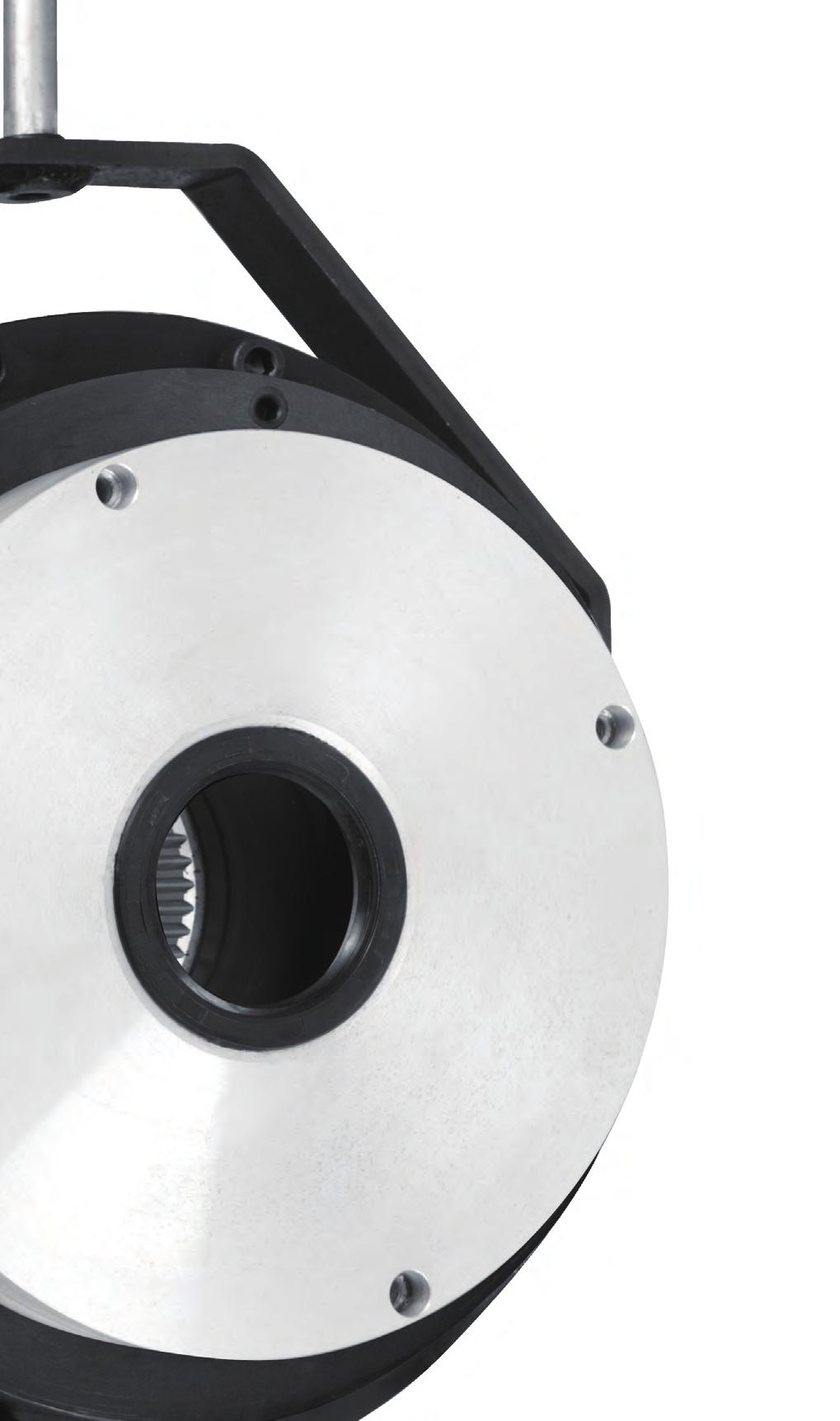
3 Focus on Sci. & Tech. Grasp Details B Series Safety brake, adopts modular design and has multiple functions, which can facilitate super rapid response with its professionally designed for low power electromagnetic coils, delicately upgraded magnetic circuit structure and special circuit board. S Series Safety brake, of high corrosion resistance and high protection, can be directly applied in open air. C Series Power-on brake, keeps interchangeability with the majority of mainstream product in the market, for extensive application. P Series Power-on brake, with backlash compensation and torque adjustability, is developed by UHT specifically for various electric cars. BH Series UHT developed the brake specifically for wind power field with features as highly-sealed and highly corrosion resistant, which can be uni-directional or bi-directional. Meanwhile we can design brakes with specific functions according to personal needs of customers.
4 Company Profile Catalog Brake Model Selection B Series- Spring-loaded Electro-magnetic Brake Features& Applications Operation Principle Rated Data Instruction for Installation Installation Dimension Table Instruction for Adjustment Attachments Product Definition Selection Form S Series- High Sealing Spring-loaded Electro-magnetic Brake Features& Applications Operation Principle Installation Dimension Table Instruction for Installation and Adjustment Product Definition Selection Form C Series- Spring-loaded Electro-magnetic Brake Features& Applications Operation Principle Installation Dimension Table Instruction for Installation Selection Product Definition Selection Form Rectifier Application for Crane Application for Wind Power Application for Forklift Truck Definition of symbols Braking torque required for dynamic load : Braking torque required for both dynamic and static load : Decelerating torque : Load torque : Rated torque of brake : Load moment of inertia : Relative rotation speed : Braking power : Friction power : Kinetic energy of gravity load : Quality of gravity load : Gravitational acceleration : Brake delay time : Friction coefficient : Friction plate equivalent radius : Friction torque : The resultant force on the armature : The spring force on the armature : The electromagnetic force produced by coil
5 Brake Model Selection Brake model selection depends totally on type of brake application. B Series brakes can be applied to general situations like power-off braking; S Series of high protection class for environments with more dust or outdoors; crane dedicated brakes for hoisting purpose; low-noise brakes for elevators, stages and other cases of low noise request. If you have special requirements on the response time or other functions of brakes in application environments, please contact suppliers. After the confirmation of brake model, the braking torque should be calculated based on the condition of loading. The calculation rules are shown below: Safety factor: K 2 Load calculation: The dynamic load is usually calculated according to the following formulas: Generally, both dynamic load and static load coexist in practical use, M load ). K M k when the braking torque and static torque have the same direction when the braking torque and static torque have the opposite directions With the known power of brake motor, the braking torque can be estimated according to the following formula: Calculation of friction power: If the braking frequency is very high and the frictional power consumption for each braking is large, the thermal load needs to be considered. The formula for calculating frictional power consumption is as follows: when the braking torque and static torque have the same direction when the braking torque and static torque have the opposite directions Notice: When calculating the friction power in the process of descent in the field of hoisting, the kinetic energy converted from the gravitational potential energy of load during the process of braking delay should also be considered in addition to the inertia of the system. The specific value should be: The actual friction power with gravity load is:

6 B Series Spring-loaded Electro-magnetic Brake Features: Power-off braking.insulation class of 155. Adjustable air gap, and long life. UHT offer products with low noise, corrosion resistance, high sealing and modular design for custom to choose Applications: Escalators, Lifts Port Machinery Crane Metallurgy Machinery Material Handling Machinery Light Industrial Packaging Textile and Printing Wood Working Machines Electrical Vehicles and Forklift Wind Mills
7 B Series Operation Principle 1.Hollow screw tube 2.Hub 3.Flange 4.Rotor 5.Friction plate 10.Screw 9.Stator 8.Springs When braking, the Rotor (4), which is installed on the Hub (2) with the splines, will be pushed by Springs (8) towards Flange (3) through Armature Plate (6), so as to produce the braking torque and the air gap generated between armature plate and Stator (9). When the brake is released, the Stator Coil (7) will be driven by DC current, and the magnetism generate force produced would make Armature Plate (6) push Springs (8) to draw to the stator, when the Rotor (4) is released, braking action is cancelled. 7.Coil 6.Armature Axial movement component Rotating component = = F F F Fixing component Assembling surface = page 7
8 B Series Rated Data Torque range For different applications, see table for the related torque value matched with the frame size: Rated torque(nm): value at Δn=100rpm Decelerating braking Load maintains rotating state because of inertia when loss of power, the friction pair keeps acting to consume residual kinetic energy to brake. Maintaining braking Rated brake torque that manufacturer offer to customers. Standard braking torque The braking strategy taken to keep position state or potential energy state of load, while the friction pair is in compressed state without relative displacement. > The impact of speed on braking torque Rated brake torque at Δn=100rpm (100%) Relationship between brake torque & Δn(rpm) (%) Maximum speed Maximum speed (rpm)
9 Response time Response time is the response time of the DC switch under 20 and rated air gap. The time depends on the value of S and adjustment method to a large extent. The braking response time of DC switch is at least 10 times faster than AC switch. Rated braking torque (Nm) Permissible friction work per cycle [J] Brake frequency under permissible friction (times per hour) The braking response time of DC switch Power relaxation time t2 ms Please take overexcitation rectifier when faster response is needed, waveform as showed below:
 Adjusting nut trip(mm) Mounting hole diameter(mm) Number and specification of mounting screw Locking torque of mounting")
10 Rated Data Rated torque Nm Rated capacity W Rated air gap mm Handle gap mm S max Decelerating braking mm S max Maintaining braking mm Min Rotor thickness mm Max Rotor thickness mm Moment of Inertia J(Kgcm 2 ) Adjusting nut trip(mm) Mounting hole diameter(mm) Number and specification of mounting screw Locking torque of mounting screw (Nm) Weight of stator Standard Voltage: 24VDC,103VDC,180VDC,205VDC. Mk:Rated torque which is measured at the relative speed Δn=100rpm Coil power (P) is the value at 20, allowable ±10% at different input voltage. Thickness of friction plate is designed that adjustment value of wear quantity is at least 5 times of rated air gap. The length of mounting screw depends on installation method of the brake. > Permissible friction work depends on the brake frequency. Frequency (times per hour)
 can be installed as showed in the picture. Fix Hub (4) on Shaft (5) axially. A clearance of 0.")
11 B Series Instruction for Installation 3.Rotor 10.Screw 7.Stator 4.Hub 5.Shaft 6.Friction plate If no suitable friction surface is available, a flange or Friction Plate (6) can be installed as showed in the picture. Fix Hub (4) on Shaft (5) axially. A clearance of 0.5-1mm is usually maintained between the hub and the installation surface so as to avoid obstructing the rotation of the shaft. The existence of this gap prevents collision between the hub and the friction dual faces in excessive axial movement. Do not knock the hub brutally; avoid inclined assembly. To preclude axial float of the hub, please fix it on the shaft with a C clip ring. Install Rotor (3) on Teeth Hub (4). The rotor and hub tooth should be alignment, wheel pushing instead of knocking brutally. In order to lower noise, seal with silica gel between the hub involute tooth profile, and then load the rotor. Insert Set Screw (10) into the hole of Stator (7) and connect it to the corresponding friction surface. Locking torque see table. Dismantle the transport support. Check the gap. Ensure the friction surface is protected from lubricating oil or grease. Energized
12 B Series Installation Dimension Table (06-16 reference drawing) Standard Standard of keyway refer to GB/T1095, the choice of shaft diameter depends on the type of load, standard of shaft hole marked with refer to GB/T1566. Unit:mm.
13 (18-30 reference drawing) L1 is the wire length. Unit: mm
 Adjustment is needed once the brake air gap S reaches the Smax.")
14 B Series Instruction for Adjustment > Data of installation and adjustment Rated air gap S Max air gap S max Handle gap S1 Tightening torque(nm) Allen wrench size(mm) Open end wrench size(mm) Service life (adjustment) Adjustment is needed once the brake air gap S reaches the Smax. Friction power consumption is a function of a multitude of factors, such as moment of inertia, braking speed, braking frequency and friction surface temperature. Therefore it is necessary to make some adjustment so as to keep the friction power consumption in an optimum status. > Installation of hand release The hand release may be installed after the brake is assembled. Firstly insert the bolt with shim and springs in the pre-opened hole so that it runs through the armature and the magnet, then install the release handle, and have it connected to the handle pin.


15 > Adjustment of air gap While the bolt loosened and power off, rotate the hollow screw tube so that the air gap is adjusted to the rated value in the table with the aid of a feeler gage. Mind that the gap is uniform on the entire perimeter. Tighten the bolt after the desired air gap is obtained. The rated air gap S increases as a result of wearing. To ensure the brake provides sufficient braking torque, the air gap must be adjusted before it reaches the maximum value (Smax) indicated in the table. The adjustment may be made repeatedly. The brake noise is closely related to the air gap value; for application where low noise is required, it is recommended to adjust the gap before it reaches the maximum value. Too excessive an air gap may result in release failure of braking power or reduced braking torque and holding torque, or even lead to serious accidents. Therefore it is imperative to check and adjust the air gap when necessary. Note that the mains switch of the machine must be off before attempting any adjustment. Adjusting method: Check the brake air gap. Release mounting screws firstly if needed to adjust gap. > Attention for installation Tighten mounting screws. Use a wrench rotating hollow screw tube to adjust air gap, rotating clockwise sense to adjust bigger, anti-clockwise sense to smaller. For the friction dual faces, the surface roughness Ra shall not exceed 3.2, the surface shall be made of smooth cast iron or steel; the friction face shall be free of any sharp point. A friction disk or flange may be used where no suitable smooth face is available. The length of key of the fixed sleeve should be the same as the length of the sleeve keyway. Temperature: The insulation level of the brake is 155, the brake shall work at an ambient temperature of -20 ~50. Humidity and water droplets: If water droplets attached on the surface of friction, friction will be temporarily low before drying, please take the strategy of protection cover installation. The brake surface will produce gel when working in high temperature difference environment, which can be solved by using heating zone or high grade packaging. In addition water attachment will lead to rust, which may cause locking in serious situation. Ventilation: The brake had better install in well-ventilated environment, because friction power consumption is transformed into heat. If forced cooling by air blower, it is very effective to increase the friction work. Please

16 Antirust: Poor storage, harsh environmental conditions and other factors will cause brake rust. The friction surface of the serious corrosion will affect the braking torque, damage the friction surface, even cause locking, although slight corrosion will not. Sparks: Brake may produce sparks because of friction. Please consider the explosion-proof design if it is used in flammable and explosive environment. Magnetic shielding of stator: The brake influenced by the measurement instruments and machines In the vicinity of it may have noise or false action, which can be solved by magnetic shielding device. Non conducting magnetic material is usually used as the material of the mounting surface and shaft of the stator. Wire protection: Brake cable of UHT has many advantages such as UV protection, anti aging, cold resistance and heat resistance and so on. If the wire is damaged, it will cause short circuit or open circuit, which should be prevented at the beginning of the design. When screw the screw on flange through the brake, there should be a hole with Φ6 and depth no less than d1 between end covers of electric generators and flange, which ensure adjustment of air gap. While other installation method, make sure that depth of threaded hole on end covers of electric generators is no less than 3 times of d1. > Common Malfunction Analysis Coil anomalies (including coil short circuit, open circuit, and abnormal insulation): Measure coil resistance and insulation resistance with a multimeter and a megger, check whether coil resistance and insulation is good or not. If the coil resistance or insulation is abnormal, please replace the stator. Deviation of air gap and handle gap (including too-big or too-small): Check the gap with feeler to make sure it is in specified range. Control Sequence problem: Mismatch of the electric machinery start/stop control program and brake response time, may aggravate the wear, reduce service life of the brake and the electric machinery, and even worse, wear to out of service in 3-5 days or over burnt coil. Rotor life problem: Please replace the rotor when it wears to very thin. Line problem: Please check whether the line connection is normal. Action problem: Verticality between mounting end face and shaft is too big. Rectifier exceptionally: Please check whether Micro switch become invalid, check with a multimeter whether the micro switch contact can be triggered by braking normally and whether the micro switch can be triggered manually. If the micro switch cannot be triggered manually(broken) or it cannot be triggered by braking after adjusting, please replace the micro switch. > Instruction for use of the micro switch The micro switch is applicable to actuation detection and wear detection. Adjust the air gap between the armature and the stator to the standard value while actuation detection. After the brake is powered, test whether the micro switch has the ON/OFF signals with the multimeter. If there is not a signal, check whether the brake is released (i.e. the armature is drawed by the stator coil). If it is released, open the brake and adjust the screws on the armature, which touch the micro switch contacts, until the micro switch has the signal that the brake can be released; then tighten the screws with glue and nuts. The electric generators cannot be started until the micro switch has a signal. The micro switch s trigger position can be adjusted as well to realize the gap detection. When the air gap is too long, the micro switch will not be triggered, the generator s contactor cannot actuate, so the motor will not be started. In this case, adjust the clearance between the armature and the stator to the standard value. Actuation detection and wear detection cannot be done by the same micro switch. Only one of them can be chosen. If both actuation detection and wear detection are required, please inform the supplier. Nut Adjusting bolt Stator Micro Switch
17 > Accessories of B Series Brake > Handle The handle is used to release the brake manually. After the manual operation, handle can return to its original positions automatically. The release screws are installed inside the spherical hinges of the handle and are tensioned. Gap S1 is the distance between the armature and the spacer. When the handle is installed, gap S1 should be adjusted according to the tale below reference picture reference picture Gap partial enlarged drawing Unit


18 > Dust-shield The dust-shield can prevent external dust and other dirty things from entering the brake to a large extent. It covers the brake externally and is embedded into a groove. If there is not an appropriate groove in the motor s installation side, it is suggested a flange or a friction plate be used. Unit Friction plate If there is a well-processed surface on the machine body, which cannot be used as the friction surface, e.g. the aluminum shell, the friction plate can be used. Frame size of can be provided. Unit


19 Flange The flange can be used when there is not an appropriate friction surface on the machine to use. Unit Micro switch The micro switch can detect whether the brake is released and feed back a switching value signal, to prevent the generator starting when the brake is in the operating state and protect the motor effectively. The micro switch connection mode is showed in the picture NC NO Brown Gray Black NC NO Gray Blue Black (16-30 reference picture) (12 14 reference picture)
20 B Series Product Definition Special Order Code Oil sealed aperture mm Empty: No seal end cover and oil seal 0: Dust cover without holes Hub aperture mm Braking torque (Nm) Coil voltage VDC Attachment 0: None 1: Hand release 2: Dust-shield 3: Hand release + Dust-shield Friction pair 0: None 1: Friction disc 2: Flange Rotor material Empty: Aluminum rotor T: Stainless steel rotor Rotating part 0: None 1: Rotor 2: Hub 3: Rotor & Hub 4: Low noise hub 5: Rotor & Low noise hub : Note: L: Low noise armature J: Ultra-quiet structure S: Bolts self-locking Brake type N: Non-adjustable torque R: Adjustable torque NM: Non-adjustable torque & Micro switch RM: Adjustable torque & Micro switch Brake series No.
21 B Series Selection Form Customer Name Type Voltage Torque regulation N Adjustable torque R AC input voltage 110VAC 220VAC 380VAC 440VAC Others DC input voltage 24VDC 103VDC 180VDC 205VDC Others Braking torque Cable length Rotor standard Special please indicate the cable length mm Bare wire mm standard Aluminum rotor Stainless steel rotor Hub The aperture mm Key width mm Deep groove mm Friction pair Flange Friction disc Installation Method Screws on flange through the brake Screws on end covers of electric generators through the brake and friction plate Screws on end covers of electric generators through the brake and flange Screws on end covers of electric generators through the brake Micro switch Actuation detection Wear detection Seal Manual release Dust-shield Oil Seal, oil seal installation section of the shaft diameter mm The sealing cover is blocked Handle release Screw release Other, please contact our technical department to communicate Other requirements Special Applications Elevator/stage Chain hoist Wire rope hoist Brake type
22 Tianjin UHT Science and Technology Co.,Ltd. No.7, Xiangrui Road, Tianxiang Industrial Park, Xiqing Economic Development Zone, Tianjin Zip code: Tel: Fax:
Focus on Sci. & Tech. Grasp Details
 Focus on Sci. & Tech. Grasp Details B Series Safety brake, adopts modular design and has multiple functions, which can facilitate super rapid response with its professionally designed for low power electromagnetic
Stromag Dessau. safety in motion PRODUCT CATALOGUE. NFF4F-LS Brake. for Slow-Running High Torque Drivelines, in harsh environment
 Stromag Dessau safety in motion PRODUCT CATALOGUE NFF4F-LS Brake for Slow-Running High Torque Drivelines, in harsh environment ENGINEERING THAT MOVES THE WORLD Applications Holding brake variations with
5-Phase Stepper Motor
 Ordering Information Application model: Standard shaft type, Hollow shaft type, Shaft type+ A 8K M 5 6 6 B Motor type Motor phase Rated current Max. Holding torque Shaft type Motor length : provides single
COMBIBOX. Program Schedule. Design. COMBIBOX clutch-brake-combination type 10 / 09 / 06. Attachments
 clutch-brake-combination 10 / 09 / 06 with an energised to engage single sided clutch / brake... 10 with an energised to engage single sided clutch without brake... 09 with an energised to engage single
Lenze spring applied brakes
 Type BFK 458 N Spring applied, electromagnetic release Factory preset torque Simple, quick assembly Adjustable for wear Very robust Torques 2 to 600 Nm S1 continuous rated Static and dynamic braking No
Stearns Heavy Duty Clutches & Brakes... Rugged, Reliable
 Stearns Heavy Duty Clutches & Brakes... Rugged, Reliable Stearns heavy duty clutches and brakes represent over 75 years of design, engineering and on-the-job experience. Stearns products are backed by
COMBIBOX Program Schedule. Design. COMBIBOX Clutch-brake-combination type 10 / 09 / 06. Attachments input
 COMBIBOX Program Schedule COMBIBOX Clutch-brake-combination type 10 / 09 / 06 with an energised to engage single sided clutch / brake COMBIBOX 10 page 37 with an energised to engage single sided clutch
POWER TRANSMISSION. Product range
 POWER TRANSMISSION Product range Product range Business Unit Power Transmission Since the firm was established in 1911 by Wilhelm Binder, the Power of Magnetism has always been the essential principle
Brakes. KNOTT Electromagnetic Release Spring-Applied Dual-Surface Fail-Safe Brakes TYPE ERA, ERB, ERC ELECTROMAGNETIC
 Brakes ELECTROMAGNETIC KNOTT Electromagnetic Release Spring-Applied Dual-Surface Fail-Safe Brakes TYPE ERA, ERB, ERC www.knott.de We make your brake 1 KNOTT manufacture a wide range of electromagnetic
ELECTROMAGNETIC DISC BRAKES H2SP SERIES WITH CONSTANT BRAKING TORQUE
 ELECTROMAGNETIC DISC BRAKES SERIES WITH CONSTANT BRAKING TORQUE K-EN--20151203 TD 223a Spring actuated and electromagnetically released disk brake type powered by direct current. Designed for braking rotating
COMBISTOP NEW. Spring applied brakes
 COMBISTOP NEW Spring applied brakes With manufacturing sites on three continents and a global sales network KEB ensures worldwide availability and support of the KEB COMBISTOP 38. This latest generation
D58 Series Brake Instructions
 D58 Series Brake Instructions 4740 W. Electric Avenue Milwaukee, WI 53219 414/672-7830 FAX 414/672-5354 www. dingsbrakes.com Safety information 2 Safety information 2.1 Persons responsible for the safety
Electromagnetic clutch-brake combinations INTORQ
 Electromagnetic clutch-brake combinations INTORQ 14.800 14.867 7.5 120 Nm setting the standard 2 CBC en 5/2005 Contents Clutch-brake combinations Product information 4 Type code 6 Design selection 8 Overview
Electromagnetic clutches and brakes INTORQ and INTORQ
 Electromagnetic clutches and brakes INTORQ 14.105 and INTORQ 14.115 7.5 480 Nm setting the standard Product information INTORQ electromagnetic clutches and brakes transmit the drive torque or braking torque
ELECTROMAGNETIC CLUTCH AND BRAKE UNITS
 -ACTUATED CLUTCHES AND BRAKES CLUTCH AND BRAKE UNITS Application Printing machinery, bookbinding machinery, woodworking machinery, semiconductor manufacturing equipment Connection and Release, Required
Technical Explanation for Inverters
 CSM_Inverter_TG_E_1_2 Introduction What Is an Inverter? An inverter controls the frequency of power supplied to an AC motor to control the rotation speed of the motor. Without an inverter, the AC motor
Catalog Mars Low voltage Brake motors
 Catalog Mars 2014 Low voltage Brake motors We provide motors, generators and mechanical power transmission products, services and expertise to save energy and improve customers processes over the total
COMBIBOX. Program Schedule. with an energised to engage single sided clutch without brake... COMBIBOX 09
 COMBIBOX clutch-brake-combination 10 / 09 / 06 with an energised to engage single sided clutch / brake... COMBIBOX 10 with an energised to engage single sided clutch without brake... COMBIBOX 09 with an
Introduction to Armature Actuated Brakes (AAB) Operating Principle. Engaged Condition (power off) Disengaged Condition (power on)
 Operating Principle. Engaged Condition (power off) Disengaged Condition (power on)") Introduction to Armature Actuated Brakes (AAB) The Armature Actuated Brakes are spring-set, electrically released, friction devices, which develop holding and braking torque in the absence of electrical
Introduction to Armature Actuated Brakes (AAB) The Armature Actuated Brakes are spring-set, electrically released, friction devices, which develop holding and braking torque in the absence of electrical
The gear boxes can be run at the same speeds as the actuator models. Do not exceed torque ratings.
 1. What is the lifting torque required? The lifting torque for a single actuator depends on the load, the worm gear ratio, type of screw (machine cut or ball screw) and the pitch of the lifting screw.
BRAKE MOTORS. 1. Brake motors TECHNICAL CATALOGUE. M Series / Standard / IEC
 1. Brake motors Standard motors (TS, TH, TP, D) can be constructed as brake motors (TBS, TBH, TBP, DB) when the driven machine must be stopped quickly and safely. This is done without modifying the motor
Lenze. Drives with worm gearboxes 52.
 6 887 Lenze Drives with worm gearboxes 5. Lenze Drive Systems GmbH, Postfach 0 5, D-76 Hameln, Site: Groß Berkel, Hans-Lenze-Straße, D-855 Aerzen, Phone ++9 (0) 55 8-0, Telefax ++9 (0) 55 8- E-Mail: Lenze@Lenze.de
Power Jacks have taken time, engineering excellence and the best people to produce the ultra compact Neeter Drive gearbox.
 202 www.powerjacks.com Power Jacks have taken time, engineering excellence and the best people to produce the ultra compact Neeter Drive gearbox. Our expertise has been built on a history of engineering
TECHNICAL GUIDE FOR PROXIMITY SENSORS DEFINITIONS YAMATAKE PROXIMITY SENSOR CATEGORIES
 TECHNICAL GUIDE FOR PROXIMITY SENSORS DEFINITIONS "" includes all sensors that detect the presence of a metallic object approaching the sensing face or near the sensing face without mechanical contact.
Installation and Operating Instructions for ROBA-stop -silenzio Type 896._3_. Sizes
 Please read and observe this Operating Instruction carefully! A possible malfunction or failure of the clutch and damage may be caused by not observing it. Table of contents: Page 1: - Table of contents
Stepper Motors ver ver.5
 A Stepper s Stepper s A-1 Overview... A-2 Overview and... A-15 & Stepper and RK Series A-16 RK... A-47... A-51 Stepper Series A-52 Stepper Series A-8 See Full Product Details Online www.orientalmotor.com
Shaft Couplings Flange-Couplings Rigid Shaft Couplings Flexible Couplings
 Shaft Couplings Flange-Couplings Rigid Shaft Couplings Flexible Couplings 44 Edition 2013/2014 RINGSPANN Registered Trademark of RINGSPANN GmbH, Bad Homburg 2 Table of Contents Flange-Couplings Page Flange-Couplings
Crane Control Class 5010
 WB F s and Rectifiers Catalog CONTENTS Descriptions....................................................Page DC Magnetic Drum s General Information................................................. 14 Pricing
ELECTRICAL. Contents - Wiring Diagrams
 Contents - Wiring Diagrams T-Bar (Floating Deck - Hydro)............................................ 8-16 T-Bar (Fixed Deck - Gear)............................................... 8-17 T-Bar (Fixed Deck
Installation and Operating Instructions for ROBA-stop -Positioning Brake Type 80_.41_._ Sizes 3 11
 Please read and observe this Operating Instruction carefully! A possible malfunction or failure of the brake and any damage may be caused by not observing it. Table of contents: Page 1: Page 2: Page 3:
Contents. SKF Grid Couplings Selection... 34
 SKF Couplings Contents The SKF brand now stands for more than ever before, and means more to you as a valued customer. While SKF maintains its leadership as a high-quality bearing manufacturer throughout
70 Series 8700 End Mount Three Phase Brake Instructions IP43 (NEMA 2) Housing
 Housing") Bulletin No. BK4772S-3 (6/2017) 70 Series 8700 End Mount Three Phase Brake Instructions IP43 (NEMA 2) Housing Read carefully before attempting to assemble, install, operate or maintain the product described.
Bulletin No. BK4772S-3 (6/2017) 70 Series 8700 End Mount Three Phase Brake Instructions IP43 (NEMA 2) Housing Read carefully before attempting to assemble, install, operate or maintain the product described.
Operating & Installation Manual
 Operating & Installation Manual (ZH1.5kw wind turbine system) Company Name:YUEQING ZONHAN WINDPOWER CO.,LTD. Address:NO.195,Chengxi Road,Yuecheng,Yueqing,Zhejiang,P.R.China Zip Code:325600 Tel:86-577-62529820
Bowl feeder WV401-1 / Translation of operating and installation instructions
 Bowl feeder WV401-1 / 402-1 Translation of operating and installation instructions Copyright by Afag GmbH This operation instruction applies to: Bowl feeder WV401-1 Bowl feeder WV402-1 Type 230 V / 50
ROBATIC ROBA -quick ROBA -takt. Reliable coupling and braking.
 Reliable coupling and braking Equipment Technology Packaging Machinery Conveyors and Materials Handling Equipment Door drives Indexing tables ROBATIC ROBA -quick ROBA -takt www.mayr.de Electromagnetic
Characteristics of model K brake
 Characteristics of model K brake The brake model K is a spring applied d.c. brake. It has been designed to stop rotational movement of machine shaft. However the user has to ensure that the brake is in
DISC BRAKES. Section 4. Components and Operation of Disc Brakes. Disc Brake Assembly
 DISC BRAKES Components and Operation of Disc Brakes A disc brake assembly consists of a: cast iron disc (disc rotor) that rotates with the wheel. caliper assembly attached to the steering knuckle. friction
W22 Brake Motor Three-phase Electric Motor
 Motors Automation Energy Transmission & Distribution Coatings W22 Brake Motor Three-phase Electric Motor African Market -- Visual index Main motor parts 1 Sealing system 8 Fan 2 Endshields 9 Bridge rectifier
Transmission Overhaul Procedures-Bench Service
 How to Assemble the Lower Reverse Idler Gear Assembly Special Instructions In 1996 Eaton changed the reverse idler system design. In the nut design, the reverse idler bearing was lubricated through a hole
New Product. High speed transfer 0.5 sec./cycle realized. Linear type P&P unit. PPLX Series PPLX SERIES CC-N-371A 4
 High speed transfer 0.5 sec./cycle realized New Product Linear type P&P unit PPLX Series PPLX SERIES CC-N-371A 4 Lb stroke length (vertical) Reliable and high speed transfer 0.5 second/cycle Available
TORQUE TRANSDUCER TMHFB-*NM (for Torque Transducer) Instruction Manual. MinebeaMitsumi Inc. Sensing Device Business Unit
 Instruction Manual. MinebeaMitsumi Inc. Sensing Device Business Unit") TORQUE TRANSDUCER TMHFB-*NM (for Torque Transducer) Instruction Manual MinebeaMitsumi Inc. Sensing Device Business Unit Please read this manual thoroughly before attempting to use the equipment. Be sure
TORQUE TRANSDUCER TMHFB-*NM (for Torque Transducer) Instruction Manual MinebeaMitsumi Inc. Sensing Device Business Unit Please read this manual thoroughly before attempting to use the equipment. Be sure
70 Series 8700 End Mount Three Phase Brake Instructions IP56 (NEMA 4) Housing
 Housing") Bulletin No. BK4773-3 (08/2016) 70 Series 8700 End Mount Three Phase Brake Instructions IP56 (NEMA 4) Housing Read carefully before attempting to assemble, install, operate or maintain the product described.
Bulletin No. BK4773-3 (08/2016) 70 Series 8700 End Mount Three Phase Brake Instructions IP56 (NEMA 4) Housing Read carefully before attempting to assemble, install, operate or maintain the product described.
setting the standard BFK468 spring-applied brake The Performance Standard 100-2,400 Nm
 setting the standard BFK468 spring-applied brake The Performance Standard 100-2,400 Nm www.intorq.de We set the standards The INTORQ brand stands for reliable brake solutions of the highest standard. Whether
Armature Actuated Brakes RoHS Compliant- meets the requirements of the Restriction of Hazardous Substances Directive
 RoHS Compliant meets the requirements of the Restriction of Hazardous Substances Directive DirectActing, DC brakes in torque ratings from 3 lbft to 300 lbft (4 Nm to 400 Nm) of torque. Dings Armature Actuated
Hunter Automatics HA-8. Installation Manual
 Hunter Automatics HA-8 Installation Manual WARNING TO REDUCE RISK OF INJURY 1. READ AND FOLLOW ALL INSTALLATION INSTRUCTIONS CAREFULLY. FAILURE TO DO SO MAY RESULT IN PERSONAL INJURY OR PROPERTY DAMAGE
Drive pinion and ring gear,
 Page 1 of 38 39-166 Drive pinion and ring gear, adjusting General notes: Drive pinion and ring gear must be very carefully adjusted to ensure long service life and smooth running. At the factory, drive
Brakes. KNOTT Electromagnetic Release Spring-Applied Dual-Surface Spring applied Brakes ELECTROMAGNETIC
 Brakes ELECTROMAGNETIC KNOTT Electromagnetic Release Spring-Applied Dual-Surface Spring applied Brakes TYPE ERG www.knott.de We make your brake KNOTT Electromagnetic Release Spring-Applied Dual-Surface
Commissioning & Maintenance Instructions. for. COBRA linear stepping motors
 Commissioning & Maintenance Instructions for COBRA linear stepping motors ACP&D Limited. 86 Rose Hill Road, Ashton-under-Lyne, Lancashire, OL6 8NS. Tel : +44 (0)161 343 1884 Fax: +44 (0)161 343 7773 e-mail:
Permanent magnet brakes. Safety from the market leader. PM Line High Torque Line
 Permanent magnet brakes Safety from the market leader PM Line High Torque Line Industrial Drive Systems Die Welt von Kendrion Industrial Drive Systems Kendrion The brake experts As a solution provider,
Ball Rail Systems RE / The Drive & Control Company
 Ball Rail Systems RE 82 202/2002-12 The Drive & Control Company Rexroth Linear Motion Technology Ball Rail Systems Roller Rail Systems Standard Ball Rail Systems Super Ball Rail Systems Ball Rail Systems
user's manual nx frequency converters brake resistors
 user's manual nx frequency converters brake resistors INDEX Document code: ud00971e Date edited: 1.10.010 1. GENERAL... 3 1.1 Requirement for braking... 3 1. Brake components... 3 1.3 Classes of use...
High-Efficiency AR Series. RK Series /0.72 /Geared. CRK Series. RBK Series. CMK Series. 2-Phase Stepping Motors A-278.
 A Stepping Motors Stepping Motors Introduction A-2 Introduction AC Power Supply Input Stepping Motor and Driver Packages A-17 DC Power Supply Input Stepping Motor and Driver Packages Stepping Motors (Motor
...components in motion. Miniature Linear Guideways
 ...components in motion Miniature Linear Introduction Miniature linear guideway systems are widely used throughout industry for precise, compact applications. Precise and Stainless The gothic arch shape
DFQ-1G-T Cutting machine control system. Operating Manual
 R software version:v1.0 DFQ-1G-T Cutting machine control system Operating Manual DFQ-1G-T cutting machine control system v1.0 Current length: Current speed: 000000M 000M/Min Up winding tension Up winding
MSW020/025-E [A895]; MPB040-E [B827]; MPW045-E [B802]; MPW050-E [C802] PART NO YRM
![MSW020/025-E [A895]; MPB040-E [B827]; MPW045-E [B802]; MPW050-E [C802] PART NO YRM](/thumbs/84/91174859.jpg "MSW020/025-E [A895]; MPB040-E [B827]; MPW045-E [B802]; MPW050-E [C802] PART NO YRM") Maintenance BRAKES MSW020/025-E [A895]; MPB040-E [B827]; MPW045-E [B802]; MPW050-E [C802] PART NO. 524154893 1800 YRM 1005 SAFETY PRECAUTIONS MAINTENANCE AND REPAIR When lifting parts or assemblies, make
Maintenance BRAKES MSW020/025-E [A895]; MPB040-E [B827]; MPW045-E [B802]; MPW050-E [C802] PART NO. 524154893 1800 YRM 1005 SAFETY PRECAUTIONS MAINTENANCE AND REPAIR When lifting parts or assemblies, make
CR193 Vacuum Limitamp* Contactors
 GE Electrical Distribution GEH-5306C Maintenance Instructions CR193 Vacuum Limitamp* Contactors Contents Section 1 Introduction... 3 General... 3 Section 2 Description... 4 Principle of Operation... 4
Hybrid Control System, Alpha Step
 B Hybrid Control System, Alpha Step Hybrid Control System B-1 Overview... B-2 Overview Hybrid Control System Battery-Free, Absolute Sensor Equipped AZ Series... B-16 Electric Linear Slides EZS Series AZ
Installation and Operating Instructions for ROBA-stop -silenzio Type 896. _. Sizes
 Please read and observe this Operating Instruction carefully! A possible malfunction or failure of the clutch and damage may be caused by not observing it Table of contents: Page1: - Table of contents
Installation and Operational Instructions for ROBA-stop Holding Brake Type _._
 Please read these Installation Instructions carefully and follow them accordingly! Ignoring these Instructions may lead to malfunctions or to brake failure, resulting in damage to other parts. Contents:
your reliable partner ROBA-stop K.800.V09.EN
 your reliable partner ROBA-stop K.800.V09.EN www..com your reliable partner Your Advantages When Using ROBA-stop ROBA-stop brakes attract customers because of their decided advantages in relation to operational
SMH High Torque Density
 SMH High Torque Density AC Synchronous Servo Motor Catalogue Version:C Date: January, 207 Kinavo Servo Motor(Changzhou)Ltd. Tel.: +8-0-88037 Fax: +8-0-88072 Website: http://www.kinavo.com Add.: Building
Installation and Operational Instructions for ROBATIC -clutch Types _.0 and _.0 Sizes 3 7
 Please read these Installation and Operational Instructions carefully and follow them accordingly! Ignoring these Instructions may lead to malfunction or to clutch failure, resulting in damage to other
Installation and Operational Instructions for ROBA-stop -M Brake Type 891. _. _ Sizes 2 500
 Please read these Operational Instructions carefully and follow them accordingly! Ignoring these Instructions may lead to malfunctions or to brake failure, resulting in damage to other parts. These Installation
EX Series. Electric Actuators for Ball and Butterfly Valves
 EX Series Electric Actuators for Ball and Butterfly Valves Next-Generation Electric Actuator Realization of Upgraded General-Purpose Actuators The modularization and adoption of the common parts have brought
your reliable partner ROBA-stop -M K.891.V17.EN
 ROBA-stop -M K.89.V7.EN www..com Your Reliable Brake Easy installation Class of insulation F; 00 % duty cycle C US Short switching times Different torque variants due to variable equipment Completely enclosed
TYPE 2 poles 4 poles 6 poles 8 poles 2 / 4 poles 4 / 8 poles 2 / 8 poles 4 / 16 poles
 BAH-BAHS series Overwiew MGM Electric Motors was established in 1950 as a brake motors manufacturer. MGM is today a world leading manufacturer of this line of products. MGM brake motors are designed and
Sibre All Steel Couplings
 Overview Coupling is device to transmit torque from driving side to driven side and also has function of compensation of axial,radial,angular misalignment which generated by manufacturing, installation
BRAKE SYSTEM FUNDAMENTALS KARAN BHARDIYA ASSISTANT MANAGER -R&D ENDURANCE TECHNOLOGIES PVT.LTD. DISC BRAKES
 BRAKE SYSTEM FUNDAMENTALS KARAN BHARDIYA ASSISTANT MANAGER -R&D ENDURANCE TECHNOLOGIES PVT.LTD. DISC BRAKES AUTOMOTIVE BRAKING SYSTEMS How brakes manufacturing industry is different then rest of the automotive
FLEXIBLE COUPLINGS - RIGID COUPLINGS Up to Nm of torque and 205 mm bores
 Edition 10/2014 www.comintec.it FLEXIBLE COUPLINGS - RIGID COUPLINGS Up to 130.000 Nm of torque and 205 mm bores (BACKLASH FREE) Technology for Safety FLEXIBLE COUPLINGS - RIGID COUPLINGS (BACKLASH FREE):
3. BEARING ARRANGEMENT DESIGN
 3. BEARING ARRANGEMENT DESIGN 3.1 GENERAL PRINCIPLES OF ROLLING BEARING ARRANGEMENT DESIGN Rotating shaft or another component arranged in rolling bearings is guided by them in radial as well as in axial
Creating Linear Motion One Step at a Time
 Creating Linear Motion One Step at a Time In classic mechanical engineering, linear systems are typically designed using conventional mechanical components to convert rotary into linear motion. Converting
Linear Actuator with Toothed Belt Series OSP-E..B
 Linear Actuator with Toothed Belt Series OSP-E..B Contents Description Data Sheet No. Page Overview 1.20.001E 21-24 Technical Data 1.20.002E-1 to 5 25-29 Dimensions 1.20.002E-6 30 Order Instructions 1.20.002E-7
Electrically Released Brakes ERS VAR11-01 FT = 4100 N
 SM429gb - rev 06/11 S E R V I C E Electrically Released Brakes ERS VAR11-01 FT = 4100 N M A N U A L EC type certificate ABV 775/1 According to drawing 1 12 106946 TUV SUD Industrie Service WARNER ELECTRIC
Electromagnetic tooth clutch Type 546
 Electromagnetic tooth clutch Type 546 Characteristics and features high torque transfer despite compact dimensions positive-locking transmission of torque without slip engageable also at low relative speed
Flexible Couplings 44
 Flexible Couplings 44 RINGSPANN Registered Trademark of RINGSPANN GmbH, Bad Homburg MTY (81) 83 54 10 18 Why RINGSPANN Flexible Couplings? No connection of shafts without clutches It is a well-known fact
SISU DP-330 DRIVE GEAR. Maintenance Manual
 SISU DP-330 DRIVE GEAR Maintenance Manual Sisu Axles, Inc. Autotehtaantie 1 PO Box 189 Fin-13101 Hameenlinna Finland Phone +358 204 55 2999 Fax +358 204 55 2900 DP330DG.PDF (3/2007) TABLE OF CONTENTS
AK-G/AK-GB/AK-R/AK-RB Series
 4mm/ 6mm/ 85mm Geared type/geared+rake built-in type 6mm Rotary actuator type/ Rotary actuator+rake built-in type Features Compact design and light weight with high accuracy, speed and torque Cost-effective
Actuator specifications
 Direct drive actuator compatible type X4000G Series Compatible with large load moment of inertia Compatible function with free driver, actuator, and cable combinations Different options including hollow
Installation and operational instructions for ROBA-stop -M Brake Type 891. _. _ Sizes 2 500
 Please read these Operational Instructions carefully and follow them accordingly! Ignoring these Instructions may lead to malfunctions or to brake failure, resulting in damage to other parts. These Installation
AC Motor Brakes. General Information. Features. Add-On Brakes. Spring Applied Power-Off Operation. Motor Brake Coil Current. Mounting.
 Spring Applied Power-Off Operation Power-Off Operation Inertia Dynamics AC-style, spring applied motor brakes are designed to decelerate or park inertial loads when the voltage is turned off, either intentionally
Therefore, it is the general practice to test the tooth contact and backlash with a tester. Figure 19-5 shows the ideal contact for a worm gear mesh.
 19. Surface Contact Of Worm And Worm Gear There is no specific Japanese standard concerning worm gearing, except for some specifications regarding surface contact in JIS B 1741. Therefore, it is the general
TQ-TQK-TR-MP LC-LCK-SL-KR Series. Precision Planetary Gearboxes
 TQ-TQK-TR-MP LC-LCK--KR Series Precision Planetary Gearboxes OUR PRODUCTS AT A GLANCE PRODUCT INLINE RIGHT ANGLE PRODUCT LINE-UP CONFIGURATIONS HIGH PERFORMANCE NEW TQ NEW TQK Yes Yes Highest Precision
Accessories smart additions for efficiency and intelligent performance
 smart additions for efficiency and intelligent performance Metal bellows couplings Perfectionists you can count on Metal bellows couplings are designed for the highest requirements in servo drive technology.
Standard AC Motors C-9
 Standard AC C-9 Overview, Product Standard AC Constant Speed Constant Speed Reversible Reversible Brake Brake Clutch & Brake Clutch & Brake Synchronous Synchronous Torque Watertight, Dust-Resistant Gearheads
Constant Speed Motors
 Standard AC Standard AC Constant Speed Brake High-Strength, Long Life, Low Noise V Series Constant Speed Torque Brake V Series TM Series Torque Features and Types of Constant Speed C-10 How to Read Specifi
Modular Explosion Proof Brakes. IECLine rev 0
 Modular Explosion Proof Brakes IECLine 2013 rev 0 Application example Standard B5 motor + VIS brake Standard B5 motor + VIS brake + gearbox unit Main Characteristics -PATENT pending design and concept
For advanced drive technology CLAMPEX. Shaft-Hub-Connection. KTR Precision Joints CLAMPEX
 technology CLAMPEX Shaft-Hub-Connection CLAMPEX KTR Precision Joints 07 technology Table of contents Page Brief information 09 Selection and calculation -5 CLAMPEX -Selection Shaft diameter = d 0 10 0
Instruction Manual. Table of Contents. Powder Clutch, Brake MODEL ZKB-AN,BN Powder Clutch ZKB-YN,XN Powder Brake
 ZJ-267A Powder Clutch, Brake MODEL ZKB-AN,BN Powder Clutch ZKB-YN,XN Powder Brake Instruction Manual Table of Contents Cautions on Safety - - - - - - - - - - - - - - - - - 1 1. Cautions before use - -
Hyponic. Quick-Start Guide. Manual
 Hyponic Quick-Start Guide 1 Manual 12.002.61.008 Hyponic Safety Consult the factory if Hyponic products are driven by DC motors, variable frequency AC drives, or speeds other than standard catalog input
Series W C D PACKAGING FOOD & BEVERAGE STEEL PULP & PAPER MINING. Cone Drive Operations, Inc. 240 East 12th Street Traverse City, MI 49684, USA
 PACKAGING FOOD & BEVERAGE STEEL PULP & PAPER MINING C D Cone Drive Operations, Inc. 240 East 12th Street Traverse City, MI 49684, USA T +1 888 994 2663 E orders@conedrive.com W www.conedrive.com ACCUDRIVE
BAH series Use and Maintenance Manual
 Page 1 of 15 BAH 225-280 series Use and Maintenance Manual Page 2 of 15 We would like to thank you for trusting us and buying our product. Field of application Before starting the motor, it s necessary
TYPE KF UNDER-FREQUENCY RELAY A. Figure 1: Type KF Relay for 60 Hertz without Case. (Front & Rear View.) Front View Rear View
 Front View Rear View") 41-503.21A TYPE KF Front View Rear View Figure 1: Type KF Relay for 60 Hertz without Case. (Front & Rear View.) 2 TYPE KF 41-503.21A lower pin bearing, which is mounted on the frame, with respect to the
41-503.21A TYPE KF Front View Rear View Figure 1: Type KF Relay for 60 Hertz without Case. (Front & Rear View.) 2 TYPE KF 41-503.21A lower pin bearing, which is mounted on the frame, with respect to the
Now you can get design flexibility and lasting performance from our complete family of AccuDrive Precision Products.
 ACCUDRIVE PRECISION PRODUCTS Now you can get design flexibility and lasting performance from our complete family of AccuDrive Precision Products. Series W Precision Servo Gearhead Output torque up to 8,500
Standard with cone bushing. Backlash-free Safety Clutch
 EAS -Compact ratchetting clutch/synchronous clutch The Backlash-free Safety Clutch for Standard with cone bushing Packaging Machinery Machine Tools Paper Machinery Indexing Drives Servo Motors EAS -NC
MAGNETIC PROXIMITY SWITCHES
 Bestact MAGNETIC PROXIMITY SWITCHES Vane PSMO Separate PSMS Memory PSMM Column PSMS_RV Omnidirectional Sensor PSMT A Wide Variety of s Available to Meet Applications/Specifications for General Purpose,
TRADITIONAL SHAFT HUB CONNECTIONS
 TABLE OF CONTENTS MAV locking devices.... Pg. 2 Traditional shaft hub connections...pg. 3 Advantages of MAV locking devices...pg. 4 The wedge principle..... Pg. 5 Installation removal...pg. 6 Characteristics....
MAXITORQ ELECTRICALLY ACTUATED CLUTCHES AND BRAKES
 MAXITORQ ELECTRICALLY ACTUATED CLUTCHES AND BRAKES HOW TO SELECT THE CORRECT CLUTCH OR BRAKE The easiest way is to ask our application engineers. For clutch application, we need to know: Torque or H.P.
Bevel gearboxes. Catalogue
 Bevel gearboxes Catalogue INDEX Bevel gearbox description... page 2 Manufacturing features... page 2 Materials and components... page 4 Bevel gearbox selection... page 5 Thermal power limit... page 7
60 Series End-Mount Brake Instructions Standard Housing
 Bulletin No. BK4655 (04/18) 60 Series End-Mount Brake Instructions Standard Housing Read carefully before attempting to assemble, install, operate or maintain the product described. Protect yourself and
SARAVEL CENTRIFUGAL FANS For Airconditioning & Industrial Application
 CAT.NO. 120-97 SARAVEL CENTRIFUGAL FANS For Airconditioning & Industrial Application TABLE OF CONTENTS Introduction......3 Selection Examples......4-5 Correction Factors......6 Rating Tables.........7-17