US Catalog January Motor protection and control Manual motor starters, contactors and overload relays
|
|
|
- Irene Webster
- 5 years ago
- Views:
Transcription


1 US Catalog January 2017 Motor protection and control Manual motor starters, contactors and overload relays
2 Motor rated operational powers and currents The currents given below concern standard three-phase four-pole cage motors (1800 r.p.m. at 60 Hz 1500 r.p.m. at 50 Hz). These values are given for guidance and may vary according to the motor manufacturer and depending on the number of poles. UL / CSA Motor nominal current: standardized values (according to UL A Annex G and UL 508 CSA C22.2 No.14) Motor power 120 V 240 V 208 V V V V V 1-ph 1-ph, -ph -ph -ph -ph -ph -ph hp A A A A A A A 1/ / / / / / / / / IEC Motor nominal current: standardized values in blue (according to IEC Annex G) Motor power 220 V 20 V 240 V 80 V 400 V 415 V 440 V 500 V 660 V 690 V kw A A A A A A A A A A
3 Motor protection and control Manual motor starters, contactors and overload relays Overview 1 Manual motor starters 2 Mini contactors AF, EK contactors and NF contactor relays 4 Overload relays 5 DRAF 6 Bar contactors 7 Certifications and approvals General technical data 8 Index 9 Marketing material 10 US Catalog Motor Protection and Control 1/1
4 -pole contactors Mini contactors Contactors for motor control and 1 IEC 1) AC- Rated operational power θ 60 C 2), 400 V kw UL/CSA -phase motor rating 480 V hp AC / DC Control supply Type AF09 AF12 AF16 AF26 AF0 AF8 AF40 AF52 AF65 AF80 AF96 AC Control supply Type B6 B7 AF09 AF12 AF16 AF26 AF0 AF8 AF40 AF52 AF65 AF80 AF96 DC Control supply Type BC6 BC7 AF09 AF12 AF16 AF26 AF0 AF8 AF40 AF52 AF65 AF80 AF96 IEC AC- Rated operational current θ 60 C 2), 400 V A AC-1 Rated operational current θ 40 C, 690 V A 20 (400 V) 20 (400 V) UL/CSA General use rating 600 V A 12 (00 V) NEMA NEMA Size ) 1000 V IEC ratings available for AF80, AF96 and AF146 AF2650 contactors. 2) θ 55 C for mini contactors and AF AF2650 contactors. Main accessories Auxiliary contact blocks Front mounting CAF6 CA4-10 (1 x N.O.) CA4-01 (1 x N.C.) Side mounting CA6 CAL4-11 (1 x N.O. + 1 x N.C.) Timers Electronic TEF4-ON TEF4-OFF Interlocking units ) Mechanical VM4 VM96-4 Mechanical / Electrical VEM4 Connection sets For reversing contactors BSM6-0 BER16-4 BER8-4 BER65-4 BER96-4 Surge suppressors Varistor (AC/DC) RV-BC6 Built-in surge protection RC type (AC) Transil diode (DC) RD7 ) See available reversing contactors VB6, VB7 and VAS09... VAS16. Overload relays Thermal relays Class 10 (Class 10A for TF140, TA200DU) T16 ( A) TF42 ( A) TF65 ( A) TF96 ( A) Electronic relays Class 10E, 20E, 0E E16DU ( A) EF19 ( A) EF19 ( A) EF45 (9 45 A) Manual motor starters Thermal / magnetic protection Class 10 MS116 ( A) Ics up to 50 ka for class 10A MS116 ( A) lcs up to 50 ka for class 10A EF65 ( A) EF96 ( A) MS165 4) ( A) lcs up to 100 ka MS5100 ( A) Ics up to 50 ka MS12 ( A) Ics up to 100 ka MS12 ( A) lcs up to 100 ka Magnetic only types MO12 ( A) MO12 ( A) Ics up to 100 ka MS497 ( A) Ics up to 100 ka MO165 4) ( A) lcs up to 100 ka MO496 (2 100 A) Ics up to 100 ka Accessories For contactor mounting BEA7/12 BEA16-4 BEA8-4 BEA65-4 5) 4) MS165/MO165 are suitable for use with AF09... AF0 for North american applications. 5) BEA65-4 suitable for MS165 and MO165 only. MS495 ( A) Ics up to 50 ka MO5100 ( A) Ics up to 6 ka MO495 (6 100 A) Ics up to 50 ka 1/2 Motor Protection and Control US Catalog


 VM750H VM750V VM1650H BER140-4 BER205-4")
 TA200DU 66...200 A) θ 55 C EF205 (6.")


5 power switching AF116 AF140 AF146 AF190 AF205 AF265 AF05 AF70 AF400 AF460 AF580 AF750 AF1250 AF150 AF1650 AF2050 AF2650 AF116 AF140 AF146 AF190 AF205 AF265 AF05 AF70 AF400 AF460 AF580 AF750 AF1250 AF150 AF1650 AF2050 AF2650 AF116 AF140 AF146 AF190 AF205 AF265 AF05 AF70 AF400 AF460 AF580 AF750 AF1250 AF150 AF1650 AF2050 AF CAL19-11 (1 x N.O. + 1 x N.C.) CAL18-11 (1 x N.O. + 1 x N.C.) VM19 (for same size contactors) VM750H VM750V VM1650H BER140-4 BER205-4 BER70-4 BEM460-0 BEM750-0 TF140DU ( A) θ 55 C EF146 ( A) TA200DU A) θ 55 C EF205 ( A) Short-circuit protection devices MCCB and switch-fuses EF70 ( A) EF460 ( A) EF750 ( A) E1250DU ( A) US Catalog Motor Protection and Control 1/
6 4-pole contactors Mini contactors 1 IEC AC-1 Rated operational current θ 40 C, 690 V A UL/CSA General use rating 600 V A 12 (00 V) 16 AC / DC Control supply Type AC Control supply Type B6 B7 DC Control supply Type BC6 BC7 Contactor relays Mini contactor relays IEC AC-15 Rated operational current 400 V A UL/CSA Pilot duty A AC Control supply Type K6-22Z K6-1Z K6-40E DC Control supply Type KC6-22Z KC6-1Z KC6-40E AC / DC Control supply Type Bar contactors DC Circuit switching DC-1 Rated current up to 5000 A DC-/DC-5 Rated current up to 2000 A 1500 V with poles in series IOR CC to IOR CC Specific contactors DC Circuit switching 100 A, 440 V, DC-1 GA75, GAE75 types 275 to 2050 A, 1000 V, DC-1 GAF185 to GAF2050 types 1/4 Motor Protection and Control US Catalog

 IOR.. 6-..-MT to IOR.. 5100-..-MT AC/DC Coupling: LOR.")
-CC-JOR")
7 Contactors AF09 AF16 AF26 AF8 AF40 AF52 AF80 AF116 AF140 AF190 AF205 AF265 AF05 AF70 AF09 AF16 AF26 AF8 AF40 AF52 AF80 AF116 AF140 AF190 AF205 AF265 AF05 AF70 EK550 EK1000 AF09 AF16 AF26 AF8 AF40 AF52 AF80 AF116 AF140 AF190 AF205 AF265 AF05 AF70 EK550 EK1000 Contactor relays A600, Q NF22E NF1E NF40E NF22E NF1E NF40E NF22E NF1E NF40E AC Circuit switching Special versions AC-1 Rated current up to 5000 A AC- Rated power up to 1500 kw (1520 A V) IOR MT to IOR MT AC/DC Coupling: LOR.. contactors Slip ring motor control: FOR.. contactors Field discharge: AM(F)-CC-JORE contactors AC/DC Switching (N.C./N.O. main poles): NOR & JOR contactors Latching contactors for energy saving and safety requirements: AMA or AME contactors Capacitor switching 12.5 to 80 kvar UA16..RA to UA110..RA types UA16 to UA110 types US Catalog Motor Protection and Control 1/5
8
9 Manual motor starters Overview Benefits 2/2 Features 2/ Overview 2/6 2 Ordering details 0.10 to 65 A with thermal and electromagnetic protection MS116 manual motor starters 2/8 MS12 manual motor starters 2/9 MS165 manual motor starters 2/10 Ordering details 0.16 to 65 A with electromagnetic protection MO12 manual motor starters magnetic only 2/11 MO165 manual motor starters magnetic only 2/12 Ordering details 0.10 to 25 A with thermal and electromagnetic protection MS12-T circuit breakers for transformer protection 2/1 Main accessories MS116, MS12, MS165 2/14 Technical data MS116, MS12, MS165, MO12, MO165, MS12-T 2/21 Ordering details 40 to 100 A with thermal and electromagnetic protection MS5100, MS495, MS497 manual motor starters 2/2 Technical data MS5100, MS495, MS497 2/ Ordering details 70 to 100 A with electromagnetic protection MO5100, MO495, MO496 2/7 Technical data MO5100, MO495, MO496 2/8 Main accessories MS/MO5100, MS/MO49X 2/42 General accessories 2/47 For direct product details information, use order code, ex : US Catalog Motor Protection and Control 2/1

10 MS and MO manual motor starters A complete motor protection concept 2 Fuseless protection saves costs, space and ensures a quick reaction under overload and short circuit condition by switching off the motor within milliseconds. The full range of motor starters offers protection from 0.1 A to up to 100 A. The new family range has a harmonized range of accessories and offers the same features up to 65 A. Safety and protection Protect equipment and people With its broad range of manual motor starters, ABB offers protection and safety in almost every situation including hazardous areas. Save people from electrical shocks and the installation from short-circuits, overloads and phase failures while also controlling the current flow through a simple and handy ON/ OFF switch. Continuous operation Secure uptime Fuseless motor protection reduces maintenance costs and downtimes by avoiding fuse replacement after faults. Furthermore, MS12 and MS165 feature a magnetic trip indicator making troubleshooting easier. Speed up your projects Simplified design This range can be connected easily with ABB contactors or soft starters using the respective accessory. Additionally, the main range of accessories is shared across multiple starters, making planning simpler. At the same time, you can rely on ABB s global technical support. 2/2 Motor Protection and Control US Catalog


11 Protection and control A full motor protection solution 2 An all-in-one solution ABB offers protection against short-circuits, phase failures and overload together with disconnecting functionality all in one single compact product. MS116 MS12/MO12 MS165/MO165 High performance in compact size The main range of motor starters can cover short-circuit breaking capacities up to 100 ka. Also, every motor starter is temperature compensated up to 60 C, making them more reliable. Troubleshooting made easy MS12 and MS165 feature a magnetic trip indicator. This way, every tripping event will be distinguished, making troubleshooting a lot easier and faster. Always an option The MS116 and MS12 offer protection up to 2 A and a short-circuit breaking capacity of 50 ka and 100 ka, respectively all in a 45 mm housing. They are designed for high performance in addition to their compact size. US Catalog Motor Protection and Control 2/


12 Control everywhere and anytime Tuned for your application 2 Short-circuit protection and disconnection Control Overload and phase failure protection Dedicated for short-circuit protection MO motor starters offer magnetic-only protection for the same range of operational currents as MS family and shared the same accessories range. These starters can be combined with a contactor and an overload relay in order to create a full motor protection solution. Transformer protection MS12-T is an inrush compensated circuit breaker for control transformer protection. With the right selection, it provides overcurrent protection on the primary side of the transformer. This avoids expensive protection on the secondary side. EAC BV France GL Germany LR Gr. Britain DNV Norway Rina RINa Italy ABS USA Protection wherever you are The manual motor starter range is worldwide applicable. With its wide range of certifications, it covers standards like IEC, culus, CCC, EAC and ship approvals. All manual motor starters also apply to ATEX standards and will protect your motors in hazardous areas. Ready for IE motors MS116/MS12/MO12 and MS/MO165 comply with the latest standards. They are "IE ready" and will protect the new generation of high efficiency motors. 2/4 Motor Protection and Control US Catalog


13 Accessories Easy add-ons, easier control HK1 MS12 MS12-T SK1 HK1 2 H CK1 MS165 AA1 HKF1 UA1 Busbar connectors and enclosures With busbar connectors, up to 5 manual motor starters can be fitted next to each other with optional spacing for auxiliary contacts. For easier access, enclosures or door handle kits are also available. Harmonized range of accessories All types up to 65 A share the same main accessories like auxiliary contacts, signal contacts, shunt trips and under-voltage releases. This significantly slims the part list and makes selection of the right accessories easy. Safety at work With a lockable handle maintenance will be safe for every technician. For MS12 and MS165 a lock can seal the handle without the use of an additional accessory. Easy to connect Save time wiring and avoid mistakes by using a connecting link between ABB manual motor starters and soft starters or contactors. This creates harmonious and compact starter combination that is easy to mount. US Catalog Motor Protection and Control 2/5
14 Manual motor starters Overview 2 Type MS116 MS12 MS165 MS5100 Thermal and electromagnetic protection Yes Yes Yes Yes Electromagnetic protection Phase loss sensitivity Yes Yes Yes Yes Switch position ON/OFF ON/OFF/TRIP ON/OFF/TRIP ON/OFF/TRIP Magnetic trip indication - Yes Yes - Lockable handle without accessories - Yes Yes Yes Disconnecting feature Yes Yes Yes Yes Width 45 mm 45 mm 55 mm 90 mm Rated operational current Ie A A A 100 A Setting range A A A A 2) Ambient air temperature C 1) C 1) C 1) C 1) Compensated 2) For motor loads only up to 80A Accessories Auxiliary contact HKF1, HK1 AUX Signalling contact for tripped alarm SK1 AUX SA for short-circuit alarm - CK1 - Shunt trip AA1 SOR-C Undervoltage release UA1 UVR-C Table for short-circuit ratings for 480 V Selection parameters Standard range MS116 Performance range MS12, MS165, MS5100 Rated operational power Setting range for thermal release Type SCCR group installation at 480V Type SCCR group installation at 480V 480 V A MS ka MS ka A MS ka MS ka A MS ka MS ka A MS ka MS ka A MS ka MS ka / A MS ka MS ka A MS ka MS ka A MS ka MS ka A MS ka MS ka A MS ka MS ka A MS ka MS ka A MS ka MS ka MS ka A MS ka A MS ka MS ka A MS ka A MS ka MS ka A MS ka MS ka A MS ka A MS ka A MS ka A MS ka A MS ka A MS ka A MS ka Type SCCR group installation at 480V 2/6 Motor Protection and Control US Catalog
15 MO12 MO165 MO5100 MS12-T Yes Yes Yes Yes Yes ON/OFF/TRIP ON/OFF/TRIP ON/OFF/TRIP ON/OFF/TRIP Yes Yes Yes Yes Yes Yes Yes Yes Yes 45 mm 55 mm 76.2 mm 45 mm A A A A A C C C C 1) 2 HKF1, HK1 AUX HKF1 SK1 - SK1 - - CK1 AA1 SOR-C AA1 UA1 UVR-C UA1 Magnetic only MO12, MO165, MO5100 Transformer protection MS12-T Type SCCR group installation at 480V Type SCCR group installation at 480V Type SCCR group installation at 480V MO ka MS T 65 ka MO ka MS T 65 ka MO ka MS12-0.4T 65 ka MO ka MS12-0.6T 65 ka MO ka MS12-1.0T 65 ka MO ka MS12-1.6T 65 ka MO ka MS12-2.5T 65 ka MO ka MS12-4.0T 65 ka MO ka MS12-6.T 65 ka MO ka MS12-10T 65 ka MO ka MS12-12T 0 ka MO ka MO ka MS12-16T 0 ka MO ka MO ka MS12-20T 0 ka MO ka MO ka MS12-25T 0 ka MO ka MO ka Transformer protection: The instantaneous short-circuit current setting MO ka is 20 times the rated operational current. MO ka MO MO ka MO MO US Catalog Motor Protection and Control 2/7
 /")
16 MS116 manual motor starters 0.10 to 2 A with thermal and electromagnetic protection Description 2 MS MS CDC241010F0011 2CDC241001F0011 MS116 is a compact and economic range for motor protection up to 25 HP (600 V) / 2 A in width of 45 mm. Additional features include the build-in disconnect function, temperature compensation, trip-free mechanism and a rotary handle with a clear switch position indication. The manual motor starter is suitable for three- and single-phase applications. Auxiliary contacts, signaling contacts, undervoltage releases, shunt trips, power in-feed blocks and locking devices for protection against unauthorized changes are available as accessory. These are suitable throughout the MS116/MS12/MS165-range. Ordering details Rated operational power Setting range Short-circuit current rating (SCCR), group installation at 480V AC 240 V 480 V 600 V Rate instantaneous short-circuit current setting l i Catalog number Global code HP HP HP A ka A kg MS SAM250000R MS SAM250000R MS SAM250000R MS SAM250000R / MS SAM250000R /4 / MS SAM250000R / MS SAM250000R MS SAM250000R MS SAM250000R MS SAM250000R MS SAM250000R MS SAM250000R MS SAM250000R MS SAM250000R MS SAM250000R Weight (1 pc) Note: Manual motor starters should always be selected so that the actual motor current is within the setting range. Main dimensions mm, inches " " " " " " " " " " 90.54" " " " " " " 5 1.8" 1.77" 45 2." CDC242002F " " " " " " 5 1.8" 1.77" 45 2." CDC242001F0011 MS A & MS116-HKF A " MS A & MS116-HKF A 2/8 Motor Protection and Control US Catalog
 / 2 A in")
17 MS12 manual motor starters 0.10 to 2 A with thermal and electromagnetic protection Description MS12-10 MS12-2 1SBC10122F0010 2CDC241001F0011 MS12 is a compact and powerful range for motor protection up to 25 HP (600 V) / 2 A in width of 45 mm. This type has also a clear and reliable indication of fault in a separate window in the event of short-circuit tripping. Additional features include the build-in disconnect function, temperature compensation, trip-free mechanism and a rotary handle with a clear switch position indication. The manual motor starter is suitable for three- and single-phase applications. The handle is lockable to protect against unauthorized changes. Auxiliary contacts, signaling contacts, undervoltage releases, shunt trips, power in-feed blocks are available as accessory. These are suitable throughout the MS116/ MS12/MS165-range. Ordering details Rated operational power 240 V 480 V 600 V Setting range Short-circuit current rating (SCCR), group installation at 480V AC Rated instantaneous short-circuit current setting l i Catalog number Global code HP HP HP A ka A kg MS SAM50000R MS SAM50000R MS SAM50000R MS SAM50000R / MS SAM50000R /4 / MS SAM50000R / MS SAM50000R MS SAM50000R MS SAM50000R MS SAM50000R MS SAM50000R MS SAM50000R MS SAM50000R MS SAM50000R MS12-2 1SAM50000R Weight (1 pc) 2 Notes: Manual motor starters should always be selected so that the actual motor current is within the setting range. SCCR 65kA when used with current limiter series S80W-SCLxxx-SR for A. Main dimensions mm, inches " " " " " 0.22" 0.22" " " " 90.54" " " 5 1.8" 45" 1.77" " " 5 1.8" " 0.1" " " " 2CDC242015F " " " 2CDC242016F0009 MS12 10 A MS12 12 A US Catalog Motor Protection and Control 2/9
18 MS165 manual motor starters 10 to 65 A with thermal and electromagnetic protection Description 2 MS CDC241004V0015 MS165 is a compact and powerful range for motor protection up to 60 HP (600 V) / 65 A in width of 55 mm. This type has also a clear and reliable indication of fault in a separate window in the event of short-circuit tripping. Additional features include the build-in disconnect function, temperature compensation, trip-free mechanism and a rotary handle with a clear switch position indication. The manual motor starter is suitable for three- and single-phase applications. The handle is lockable to protect against unauthorized changes. Auxiliary contacts, signaling contacts, undervoltage releases, shunt trips, power in-feed blocks are available as accessory. These are suitable throughout the MS116/MS12/MS165-range. Ordering details Rated operational power 240 V 480 V 600 V Setting range Short-circuit current rating (SCCR), group installation at 480V AC Rated instantaneous short-circuit current setting l i Catalog number Global code Weight (1 pc) HP HP HP A ka A kg MS SAM451000R MS SAM451000R MS SAM451000R MS SAM451000R MS SAM451000R MS SAM451000R MS SAM451000R Note: Manual motor starters should always be selected so that the actual motor current is within the setting range. Main dimensions mm, inches " " " " " " " 5.62" 1.8" 1.77".01" 0.07" " " 2CDC242001F0014 MS165 2/10 Motor Protection and Control US Catalog
19 MO12 manual motor starters magnetic only 0.16 to 2 A with electromagnetic protection Description Manual motor starters magnetic only are electromechanical protection devices for the main circuit. They are used mainly to switch motors manually ON/OFF and protect them fuse-less against short-circuit. MO12-6. MO12-2 2CDC241009F0011 2CDC241008F0011 Fuse-less protection with a manual motor starter saves costs, space and ensures a quick reaction under short-circuit condition, by switching off the motor within milliseconds. Fuse-less starter combinations are setup together with contactors and overload relays. Ordering details Rated operational power 240 V 480 V 600 V Rated operational current Short-circuit current rating (SCCR), group installation at 480V AC Rated instantaneous short-circuit current setting l i Catalog number Global code HP HP HP A ka A kg MO SAM60000R MO SAM60000R MO SAM60000R MO SAM60000R / MO SAM60000R /4 / MO SAM60000R / MO SAM60000R MO SAM60000R MO SAM60000R MO SAM60000R MO SAM60000R MO SAM60000R MO SAM60000R MO SAM60000R MO12-2 1SAM60000R Weight (1 pc) 2 Note: For overload protection of motors, an appropriate thermal or electronic overload relay must be used. Main dimensions mm, inches " " " " " 0.22" 0.22" " " " 90.54" " " 5 1.8" 45" 1.77" " " 5 1.8" " 0.1" " " " 2CDC242005F " " " 2CDC242006F0011 MO12 10 A MO12 12 A US Catalog Motor Protection and Control 2/11

20 MO165 manual motor starters magnetic only 16 to 65 A with electromagnetic protection 2 Description Manual motor starters magnetic only are electromechanical protection devices for the main circuit. They are used mainly to switch motors manually ON/OFF and protect them fuse-less against short-circuit. Fuse-less protection with a manual motor starter saves costs, space and ensures a quick reaction under short-circuit condition, by switching off the motor within milliseconds. Fuse-less starter combinations are setup together with contactors and overload relays. MO CDC241005V0015 Ordering details Rated operational power 240 V 480 V 600 V Rated operational current Short-circuit current rating (SCCR), group installation at 480V AC Rated instantaneous short-circuit current setting l i Catalog number Global code HP HP HP A ka A kg MO SAM461000R MO SAM461000R MO SAM461000R MO SAM461000R MO SAM461000R MO SAM461000R MO SAM461000R Weight (1 pc) Main dimensions mm, inches " " " " " " " 5.62" 1.8" 1.77".01" 0.07" " " 2CDC242002F0014 M0165 2/12 Motor Protection and Control US Catalog

21 MS12-T circuit breakers for transformer protection 0.10 to 25 A with thermal and electromagnetic protection Description MS12-10T 2CDC241001F0014 Circuit breakers for transformer protection are electro mechanical protection devices specially designed to protect control transformers on the primary side. They allow fuse-less protection against overload and short-circuit, saving space and cost and ensuring a quick reaction under short-circuit condition by switching off the transformer within milliseconds. The short-circuit current setting is fixed to 20 times the operating current to handle the high inrush current generated by transformers. The device allows manual connection and disconnection of the transformer from the mains. MS12-T is a 45 mm (width) compact and powerful range for transformer protection up to 25 KW (600 V) / 25 A. This type has also a clear and reliable indication of fault in a separate window in the event of short-circuit tripping. Further features are the build-in disconnect function, temperature compensation, trip-free mechanism and a rotary handle with a clear switch position indication. The handle is lockable to protect against unauthorized changes. Auxiliary contacts, signaling contacts, undervoltage releases, shunt trips, power in-feed blocks are available as accessory. These are suitable throughout the MS116/MS12/MS165-range. Moreover ABB offers special accessories for fast single-phase setup. 2 Ordering details MS12-25T 2CDC241002F0014 Setting range Short-circuit current rating (SCCR), group installation at 480V AC Rated instantaneous short-circuit current setting l i Catalog number Global code Weight (1 pc) A ka A kg MS T 1SAM40000R MS T 1SAM40000R MS12-0.4T 1SAM40000R MS12-0.6T 1SAM40000R MS12-1.0T 1SAM40000R MS12-1.6T 1SAM40000R MS12-2.5T 1SAM40000R MS12-4.0T 1SAM40000R MS12-6.T 1SAM40000R MS12-10T 1SAM40000R MS12-12T 1SAM40000R MS12-16T 1SAM40000R MS12-20T 1SAM40000R MS12-25T 1SAM40000R Main dimensions mm, inches " " " " " 0.22" 0.22" " " " 90.54" " " 5 1.8" 45" 1.77" " " 5 1.8" " 0.1" " " " 2CDC242015F " " " 2CDC242016F0009 MS12T 10 A MS12T 12 A US Catalog Motor Protection and Control 2/1
22 Main accessories MS116, MS12, MS165, MO12, MO165, MS12-T Manual motor starters with accessories (MS116, MO12, MO165) 2 HK1 SK1 HK1 MS116 MO12 HK1 MO165 AA1 UA1 HKF1 2CDC242001F0015 Manual motor starters with accessories (MS12, MS165) and circuit breaker for transformer protection (MS12-T) HK1 SK1 HK1 MS12 MS12-T HK1 SK1 CK1 HK1 MS165 CK1 AA1 HKF1 UA1 2CDC242002F0015 2/14 Motor Protection and Control US Catalog

23 Main accessories MS116, MS12, MS165, MO12, MO165, MS12-T HKF1-11 1SBC101208F0014 Description MMS and MS12-T can be equipped with auxiliary contacts for lateral/front mounting, signaling contacts for lateral mounting, undervoltage releases and shunt trips. Two signaling contacts are available. The accessories can be fitted wiring free and without tools. A variety of combinations is possible as required for the application. The auxiliary contacts change position with the main contacts. The signaling contact SK signals tripping regardless if it was caused by short-circuit or overload. The signaling contact CK signals tripping in case it was caused by short-circuit. Undervoltage releases are used for remote tripping of the manual motor starters especially for emergency stop circuits. Shunt trips release the MMS used for remote tripping. These main accessories are suitable throughout the MS116/MS12/MS165-range. 2 HK1-11 SK1-11 CK1-11 1SBC101209F0014 1SBC101210F0014 1SBC101286F0014 Ordering details Suitable for Auxiliary contacts N.O. Auxiliary contacts N.C. Description Catalog number Global code Pkg qty Auxiliary contacts mountable on the front MS116, MS12, 1 1 HKF1-11 1SAM201901R MS165 MO12, 1 0 HKF1-10 1SAM201901R MO165 MS12-T 0 1 HKF1-01 1SAM201901R HKF1-20 1SAM201901R Auxiliary contacts mountable on the right MS116, MS12, 1 1 max. 2 pieces HK1-11 1SAM201902R MS165 MO12, 2 0 max. 2 pieces HK1-20 1SAM201902R MO165 MS12-T 0 2 max. 2 pieces HK1-02 1SAM201902R with lead contacts HK1-20L 1SAM201902R Signaling contacts mountable on the right MS116, MS12, MS165 MO12, MO165 MS12-T for tripped alarm, max. 2 pieces for tripped alarm, max. 2 pieces 0 2 for tripped alarm, max. 2 pieces MS12, MS165, 1 1 for short-circuit alarm, MS12-T max. 2 pieces 2 0 for short-circuit alarm, max. 2 pieces 0 2 for short-circuit alarm, max. 2 pieces pcs Weight (1 pc) SK1-11 1SAM20190R SK1-20 1SAM20190R SK1-02 1SAM20190R CK1-11 1SAM20190R CK1-20 1SAM01901R CK1-02 1SAM01901R kg Main dimensions mm, inches " 1.77" 2.8".54" 9 0.5" " " " " 2CDC242001F0012 HK1 US Catalog Motor Protection and Control 2/15
24 Main accessories MS116, MS12, MS165, MO12, MO165, MS12-T Ordering details 2 AA1-24 1SBC101211F0014 Suitable for Rated control supply voltage Catalog number Global code Pkg qty Weight (1 pc) 50 Hz V AC 60 Hz V AC pcs kg Shunt trips mountable on the left MS116, MS12, AA1-24 1SAM201910R MS165, MO12, AA SAM201910R MO165, MS12-T AA1-20 1SAM201910R AA SAM201910R UA1-24 1SBC101212F0014 Undervoltage releases mountable on the left MS116, MS12, UA1-20 1SAM201904R MS165, MO12, 24 - UA1-24 1SAM201904R MO165, MS12-T 48 - UA1-48 1SAM201904R UA1-60 1SAM201904R UA SAM201904R UA SAM201904R UA1-20 1SAM201904R UA SAM201904R UA SAM201904R UA SAM201904R Main dimensions mm, inches 90.54" " " " " " " 2CDC242002F0012 AA1, UA1 2/16 Motor Protection and Control US Catalog

 PS2-4-0-125 PS2-2-0-125 Three-phase busbar up to 125 A 2CDC242006F0015 BS2-2CDC242005F0015 PS2-4-0-125 Three-phase busbar up")
25 Main accessories MS116, MS12, MS165, MO12, MO165 Manual motor starter with three-phase busbar systems (MS116, MS12, MO12) S1-M2-25 S1-M-5 PS PS S1-M1-25 BS1- SA1 2CDC242021F001 2CDC242020F001 PS Three-phase busbar up to 65 A Three-phase busbar up to 92 A Manual motor starter with three-phase busbar systems (MS165, MO165) PS PS Three-phase busbar up to 125 A 2CDC242006F0015 BS2-2CDC242005F0015 PS Three-phase busbar up to 125 A US Catalog Motor Protection and Control 2/17


26 Main accessories MS116, MS12, MO12, MS12-T 2 PS PS S1-M1-25 S1-M2-25 SA2 1SBC101226F0014 1SBC101266F0014 2CDC24102F001 2CDC241017F0010 2CDC241014F0010 Description Three-phase busbars ensure a quick and safe connection and are therefore a cost effective solution. A variety of different three-phase busbars up to 92 A are in the assortment. Between 2 and 5 manual motor starters with none, one or two lateral auxiliary contacts can be connected. Different three-phase feeder terminals are available according to the application. Phase connecting links and phase power infeed blocks are also available for single-phase applications. Ordering details Suitable for Rated operational current Number of MMS Number of lateral aux. Catalog number Global code Pkg qty Weight (1 pc) A pcs kg Three-phase busbars MS116, MS12, PS SAM201906R MO PS SAM201906R PS SAM201906R PS SAM201906R PS SAM201906R PS SAM201906R PS SAM201906R PS SAM201906R PS SAM201906R PS SAM201906R PS SAM201906R PS SAM201906R MS116, MS12, MO12 Suitable for 92 0 PS SAM201916R PS SAM201916R PS SAM201916R PS SAM201916R PS SAM201916R PS SAM201916R PS SAM201916R Rated operational Rated cross Mounting form Catalog Global code Pkg Weight current section number qty (1 pc) A mm² pcs kg SA1 SK0108B91 Three-phase feeder terminals MS116, MS12, 6 25 Flat S1-M1-25 1SAM201907R MO High S1-M2-25 1SAM201907R UL/CSA Type E/F S1-M-25 1SAM201907R UL/CSA Type E/F S1-M-5 1SAM20191R PB CDC241004F0014 Suitable for Description Catalog number Global code Pkg qty Weight (1 pc) pcs kg MS116, MS12, Protection cover for busbars BS1-1SAM201908R MO12 MS116, MS12, Screw fixing kit MS116-SMF 1SAM201909R MO12, MS12-T Padlock + two keys SA2 GJF110190R MS116 Lock handle SA1 GJF110190R Lock handle box SA1/SA2 SA GJF110190R S1-PB1-25 2CDC241005S0014 Accessories for single-phase connection (IEC only) MS116, MS12, Phase connecting link PB SAM201914R MO12, MS12-T Phase power infeed block S1-PB1-25 1SAM201914R /18 Motor Protection and Control US Catalog

 A pcs kg Three-phase busbars MS165, MO165 125 2 0 PS2-2-0-125 1SAM401920R1002 10 0.10 125 0 PS2--0-125 1SAM401920R100 10 0.")
27 Main accessories MS165, MO165 Description PS PS CDC241010V0014 2CDC241002V0015 2CDC24100V0015 Three-phase busbars ensure a quick and safe connection and are therefore a cost effective solution. A variety of different three-phase busbars up to 125 A are in the assortment. Between 2 and 5 manual motor starters with none, one or two lateral auxiliary contacts can be connected. Ordering details Suitable for Rated operational current Number of MMS Number of lateral aux. Catalog number Global code Pkg qty Weight (1 pc) A pcs kg Three-phase busbars MS165, MO PS SAM401920R PS SAM401920R PS SAM401920R PS SAM401920R PS SAM401920R PS SAM401920R Note: Other busbar types available on request. 2 KA165 BS2-2CDC241001V0015 Suitable for Description Catalog number Global code Pkg qty Weight (1 pc) pcs kg MS165, MO165 Terminal shroud KA165 1SAM401922R Protection cover for busbars BS2-1SAM401921R Padlock + two keys SA2 GJF110190R SA2 2CDC24102F001 US Catalog Motor Protection and Control 2/19


 kg IB12-G 2CDC24100F0010 UL/CSA Type 12 enclosures MS116, MS12, Padlockable")

28 Main accessories MS116, MS12, MO12 Description 2 IB12-Y 2CDC241004F0010 IB12 are UL/CSA Type 12 enclosures for single MMS installation. Additional mounting of auxiliary and signaling contacts, shunt trips and undervoltage release is possible. The handle is lockable in OFF position. For detailed specification see installation instruction. DMS12 are UL/CSA Type 12 door mounting kits for MMS installation in any enclosure. Additional mounting of auxiliary, signaling, shunt trips and undervoltage release is possible. The handle is lockable in OFF position. For detailed specification see installation instruction. Ordering details Suitable for Description Color Catalog number Global code Pkg qty pcs Weight (1 pc) kg IB12-G 2CDC24100F0010 UL/CSA Type 12 enclosures MS116, MS12, Padlockable max. MO12 padlocks with bail diameter mm UL/CSA Type 12 door mounting kits MS116, MS12, Padlockable max. MO12 padlocks with bail diameter mm Yellow/red IB12-Y 1SAM201911R Grey/black IB12-G 1SAM201911R Yellow/red DMS12-Y 1SAM201912R Grey/black DMS12-G 1SAM201912R Note: Indication I-O-T and ON-OFF-T DMS12-Y 2CDC241002F0010 2CDC241001F0010 DMS12-G Main dimensions mm, inches " " " 92.62" 24.94" 7.2" 18 0 OFF I ON 6.85" 7.64" " OFF I ON 2CDC242011F " 2CDC242012F0011 IB12 DMS12 2/20 Motor Protection and Control US Catalog
29 Technical data MS116, MS12, MS165, MO12, MO165, MS12-T Main circuit Utilization characteristics according to UL/CSA Type MS116 MS12 MS165 MO12 MO165 MS12-T Standards UL , UL (UL 508), CSA C22.2 No (CSA C No.14) Rated operational voltage Ue acc. to UL/CSA 600 V AC - Trip class 10A Motor ratings 1) Horsepower See table "Motor ratings, three-phase" - Full Load Amps (FLA) See table "Motor ratings, three-phase" - Locked Rotor Amps (LRA) See table "Motor ratings, three-phase" - 2 1) See product data sheets for UL/CSA single-phase motor and general use (AC-1) ratings. UL/CSA ratings overview Type MS116 MS12 MS165 MO12 MO165 MS12-T Manual Motor Controller x x x x x - Manual Motor Controller, Suitable as Motor Disconnect x x x x x - Manual Motor Controller, Suitable for use in Group Installations x x x x x - Manual Motor Controller, Suitable for Tap Conductor Protection in Group - x x x x - Installations Manual self-protected Combination Motor Controller (Type E) - x x Combination Motor Controller (Type F) - with AF with AF with AF contactor - - contactor contactor and EOL Main circuit Utilization characteristics according to IEC/EN Type MS116 MS12 MS165 MO12 MO165 MS12-T Standards IEC/EN , IEC/EN , IEC/EN Rated operational voltage Ue 690 V AC 690 V AC / 690 V AC 690 V AC 690 V AC 690 V AC 250 V DC Rated frequency 50/60 Hz DC, 50/60 Hz 50/60 Hz 50/60 Hz 50/60 Hz 50/60 Hz Trip class 10A Number of poles Duty time 100 % Mechanical durability cycles cycles cycles cycles cycles cycles Electrical durability up to 16 A cycles cycles cycles cycles cycles cycles A cycles cycles cycles cycles cycles cycles Rated impulse withstand voltage Uimp 6 kv 6 kv 8 kv 6 kv 8 kv 6 kv Rated insulation voltage Ui 690 V 690 V 1000 V 690 V 1000 V 690 V Rated operational current Ie See ordering details US Catalog Motor Protection and Control 2/21
30 Technical data MS116, MS12, MS165, MO12, MO165, MS12-T 2 UL/CSA Motor ratings, three-phase MS116 Type 200 V AC 208 V AC V AC V AC V AC hp FLA LRA hp FLA LRA hp FLA LRA hp FLA LRA hp FLA LRA MS MS MS MS MS /2 1 6 MS / / MS / / / / MS / / MS / MS / MS / MS MS MS / / MS / UL/CSA Motor ratings, three-phase MS12 Type 200 V AC 208 V AC V AC V AC V AC hp FLA LRA hp FLA LRA hp FLA LRA hp FLA LRA hp FLA LRA MS MS MS MS MS /2 1 6 MS / / MS / / / / MS / / MS / MS / MS / MS MS MS / / MS / UL/CSA Motor ratings, three-phase MS165 Type 200 V AC 208 V AC V AC V AC V AC hp FLA LRA hp FLA LRA hp FLA LRA hp FLA LRA hp FLA LRA MS MS MS / / MS / MS MS MS hp FLA LRA Horsepower Full Load Amps Locked Rotor Amps Note: Manual motor starters should always be selected so that the actual motor current is within the setting range; see ordering detail pages. Horsepower (hp) ratings are for reference only. 2/22 Motor Protection and Control US Catalog
31 Technical data MS116, MS12, MS165, MO12, MO165, MS12-T UL/CSA Motor ratings, three-phase MO12 Type 200 V AC 208 V AC V AC V AC V AC hp FLA LRA hp FLA LRA hp FLA LRA hp FLA LRA hp FLA LRA MO MO MO MO MO /2 1 6 MO / / MO / / / / MO / / MO / MO / MO / MO MO MO / / MO / UL/CSA Motor ratings, three-phase MO165 Type 200 V AC 208 V AC V AC V AC V AC hp FLA LRA hp FLA LRA hp FLA LRA hp FLA LRA hp FLA LRA MO MO MO / / MO / MO MO MO hp FLA LRA Horsepower Full Load Amps Locked Rotor Amps US Catalog Motor Protection and Control 2/2
32 Technical data MS116, MS12, MS165, MO12, MO165, MS12-T 2 UL/CSA Maximum short-circuit current ratings MS116 Type Manual Motor Controllers Branch circuit protection, max. size per NEC/CEC 1) for motor disconnect 2) for group installations Fuses Circuit breaker 480 V 600 V 480 V 600 V A A ka ka ka ka MS MS MS MS MS MS MS MS MS MS MS MS MS MS MS ) NEC: NFPA 70 National Electrical Code ; CEC: CSA C22.1 Canadian Electrical Code. 2) Suitable as motor disconnect only when provide with padlock adaptor SA1 or SA. for motor disconnect for group installations for tap conductor protection in UL/CSA Maximum short-circuit current ratings MS12 Type Manual Motor Controllers Manual self-protected Combination Branch circuit protection, max. Motor Controllers (Type E) 2) size per NEC/CEC 1) group installations Fuses Circuit breaker 480 V 600 V 480 V 600 V 480 V 600 V 480Y / 277 V 600Y / 47 V A A ka ka ka ka ka ka ka ka MS Any Listed Any Listed MS fuses. Size UL489 / per NEC/CEC CSA C22.2 MS No.5 circuit MS breaker MS Size per NEC/CEC MS MS MS MS MS MS MS MS MS MS ) NEC: NFPA 70 National Electrical Code ; CEC: CSA C22.1 Canadian Electrical Code. 2) Requires the use of S1-M-xx line-side terminal feeder block. Note: SCCR 65kA when used with current limiter series S80W-SCLxxx-SR for A. 2/24 Motor Protection and Control US Catalog
33 Technical data MS116, MS12, MS165, MO12, MO165, MS12-T Type Combination Motor Controllers UL/CSA Maximum short-circuit current ratings MS12/MO12 with AF contactors Type Combination Motor Controllers (Type F) 1) (Type F) 1) Minimum contactor size 480Y / 277 V 600Y / 47 V Minimum contactor 480Y / 277 V 600Y / 47 V ka ka Size TOL ka ka MS AF MO AF09 TF MS AF MO AF09 TF MS AF MO AF09 TF MS AF MO AF09 TF MS AF MO AF09 TF MS AF MO AF09 TF MS AF MO AF09 TF MS AF MO AF09 TF MS12-6. AF MO12-6. AF09 TF MS12-10 AF MO12-10 AF09 TF MS12-12 AF MO12-12 AF09 TF MS12-16 AF MO12-16 AF12 TF MS12-20 AF MO12-20 AF16 TF MS12-25 AF MO12-25 AF26 TF MS12-2 AF MO12-2 AF8 TF ) Requires the use of S1-M-xx line-side terminal feeder block. for motor disconnect for group installations for tap conductor protection in UL/CSA Maximum short-circuit current ratings MS165 Type Manual Motor Controllers Manual self-protected Combination Branch circuit protection, max. Motor Controllers (Type E) size per NEC/CEC 1) group installations Fuses Circuit breaker 480 V 600 V 480 V 600 V 480 V 600 V 480Y / 277 V 600Y / 47 V A A ka ka ka ka ka ka ka ka MS Any Listed Any Listed MS fuses. Size per UL489 / NEC/CEC CSA C22.2 MS No.5 circuit MS165-2 breaker MS Size per NEC/CEC MS MS ) NEC: NFPA 70 National Electrical Code ; CEC: CSA C22.1 Canadian Electrical Code. UL/CSA Maximum short-circuit current ratings MS165/MO165 with AF contactors Type Combination Motor Controllers (Type F) Type Combination Motor Controllers (Type F) Minimum contactor size 480Y / 277 V 600Y / 47 V Minimum contactor size 480Y / 277 V 600Y / 47 V ka ka TOL ka ka MS AF MO AF09 TF MS AF MO AF26 TF MS AF MO AF26 TF MS165-2 AF MO165-2 AF26 TF MS AF MO AF40 TF MS AF MO AF40 TF MS AF MO AF40 TF US Catalog Motor Protection and Control 2/25
34 Technical data MS116, MS12, MS165, MO12, MO165, MS12-T 2 UL/CSA Maximum short-circuit current ratings MO12 Type Manual Motor Controllers Branch circuit protection, max. size per NEC/CEC 1) for motor disconnect for group installations for tap conductor protection in group installations Fuses Circuit breaker 480 V 600 V 480 V 600 V 480 V 600 V A A ka ka ka ka ka ka MO Any Listed fuses. Any Listed MO Size per NEC/ UL489 / CSA CEC C22.2 No.5 MO circuit breaker MO Size per NEC/ MO CEC MO MO MO MO MO MO MO MO MO MO ) NEC: NFPA 70 National Electrical Code ; CEC: CSA C22.1 Canadian Electrical Code. UL/CSA Maximum short-circuit current ratings MO165 Type Manual Motor Controllers Branch circuit protection, max. size per NEC/CEC 1) for motor disconnect for group installations for tap conductor protection in group installations Fuses Circuit breaker 480 V 600 V 480 V 600 V 480 V 600 V A A ka ka ka ka ka ka MO Any Listed fuses. Any Listed MO Size per NEC/ UL489 / CSA CEC C22.2 No.5 MO circuit breaker MO165-2 Size per NEC/ MO CEC MO MO ) NEC: NFPA 70 National Electrical Code ; CEC: CSA C22.1 Canadian Electrical Code. 2/26 Motor Protection and Control US Catalog
35 Technical data MS116, MS12, MS165, MO12, MO165, MS12-T General technical data Type MS116 MS12 MS165 MO12 MO165 MS12-T Pollution degree Phase loss sensitivity Yes Yes Yes No No Yes Disconnect function acc. to IEC/EN Yes Yes Yes Yes Yes Yes Ambient air temperature Operation Open - compensated C C C C Open C C C C C C Enclosed (IB12) C C C Storage C C C C C C Ambient air temperature compensation Acc. to IEC/ EN Acc. to IEC/ EN Acc. to IEC/ EN Acc. to IEC/ EN Maximum operating altitude permissible 2000 m 2000 m 2000 m 2000 m 2000 m 2000 m Resistance to shock acc. to IEC g / 11 ms 25g / 11 ms 25g / 11 ms 25g / 11 ms 25g / 11 ms 25g / 11 ms Resistance to vibrations acc. to IEC g / Hz 5g / Hz 5g / Hz 5g / Hz 5g / Hz 5g / Hz Mounting position Position 1-6 (optional for single mounting) Position 1-6 (optional for single mounting) Position 1-6 (optional for single mounting) Position 1-6 (optional for single mounting) Position 1-6 (optional for single mounting) Position 1-6 (optional for single mounting) Mounting DIN-rail (EN 60715) DIN-rail (EN 60715) DIN-rail (EN 60715) DIN-rail (EN 60715) DIN-rail (EN 60715) DIN-rail (EN 60715) Group mounting On request On request On request On request On request - Minimum distance to other Horizontal 0 mm 0 mm 0 mm 0 mm 0 mm 0 mm units same type Vertical 150 mm 150 mm 150 mm 150 mm 150 mm 150 mm Minimum distance to electrical conductive board Horizontal, up to 400 V 0 mm 0 mm 0 mm 0 mm 0 mm 0 mm Horizontal, up to 690 V > 1.5 mm > 1.5 mm > 1.5 mm > 1.5 mm > 1.5 mm > 1.5 mm Vertical 75 mm 75 mm 75 mm 75 mm 75 mm 75 mm Degree of protection Housing IP20 IP20 IP20 IP20 IP20 IP20 Main circuit terminals IP20 IP20 IP10 IP20 IP10 IP20 2 Connecting characteristics Main circuit Type MS A MS A Connecting capacity Rigid 1 or 2 x mm² mm² Flexible with ferrule 1 or 2 x mm² mm² Flexible with insulated ferrule 1 or 2 x mm² mm² Flexible 1 or 2 x mm² mm² Stranded acc. to UL/CSA 1 or 2 x AWG AWG 16-8 Stripping length 9 mm 10 mm Tightening torque Nm / Ib.in 2.0 Nm / 18 Ib.in Recommended screw driver Pozidriv 2 Pozidriv 2 Main circuit Type MS12 10 A MS12 12 A Connecting capacity Rigid 1 or 2 x mm² mm² mm² Flexible with ferrule 1 or 2 x mm² mm² Flexible with insulated ferrule 1 or 2 x mm² mm² Flexible 1 or 2 x mm² mm² mm² Stranded acc. to UL/CSA 1 or 2 x AWG AWG 16-8 Stripping length 9 mm 10 mm Tightening torque Nm / Ib.in 2.0 Nm / 18 Ib.in Recommended screw driver Pozidriv 2 Pozidriv 2 US Catalog Motor Protection and Control 2/27
36 Technical data MS116, MS12, MS165, MO12, MO165, MS12-T 2 Connecting characteristics Main circuit Type MS165 Connecting capacity Rigid 1 or 2 x mm² Flexible with ferrule 1 or 2 x mm² Flexible with insulated ferrule 1 or 2 x mm² Flexible 1 or 2 x mm² Stranded acc. to UL/CSA 1 or 2 x AWG 16- Stripping length 16 mm Tightening torque 4.0 Nm / 5 Ib.in Recommended screw driver Pozidriv 2 Main circuit Type MO12 10 A MO12 12 A Connecting capacity Rigid 1 or 2 x mm² mm² mm² Flexible with ferrule 1 or 2 x mm² mm² Flexible with insulated ferrule 1 or 2 x mm² mm² Flexible 1 or 2 x mm² mm² mm² Stranded acc. to UL/CSA 1 or 2 x AWG AWG 16-8 Stripping length 9 mm 10 mm Tightening torque Nm / Ib.in 2.0 Nm / 18 Ib.in Recommended screw driver Pozidriv 2 Pozidriv 2 Main circuit Type MO165 Connecting capacity Rigid 1 or 2 x mm² Flexible with ferrule 1 or 2 x mm² Flexible with insulated ferrule 1 or 2 x mm² Flexible 1 or 2 x mm² Stranded acc. to UL/CSA 1 or 2 x AWG 16- Stripping length 16 mm Tightening torque 4.0 Nm / 5 Ib.in Recommended screw driver Pozidriv 2 Main circuit Type MS12-T 10 A MS12-T 12 A Connecting capacity Rigid 1 or 2 x mm² 1/2 x mm² 1/2 x mm² Flexible with ferrule 1 or 2 x mm² 1/2 x mm² Flexible with insulated ferrule 1 or 2 x mm² 1/2 x mm² Flexible 1 or 2 x mm² 1/2 x mm² 1/2 x mm² Stranded acc. to UL/CSA 1 or 2 x AWG AWG 16-8 Stripping length 9 mm 10 mm Tightening torque Nm / Ib.in 2.0 Nm / 18 Ib.in Recommended screw driver Pozidriv 2 Pozidriv 2 2/28 Motor Protection and Control US Catalog
37 Main accessories MS116, MS12, MS165, MO12, MO165, MS12-T General technical data Type HK1, SK1, CK1 HKF1 Standards IEC/EN , IEC/EN , IEC/EN Rated operational voltage Ue 690 V AC / 600 DC 250 V AC / 250 V DC Conventional free-air thermal current Ith 6 A 5 A Rated frequency 50/60 Hz Rated impulse withstand voltage Uimp 6 kv Rated insulation voltage Ui 690 V AC 250 V AC Pollution degree Ambient air temperature Operation C Storage C Resistance to shock acc. to IEC g / 11 ms Resistance to vibrations acc. to IEC g / Hz Ie / Rated operational current AC-15 acc. to IEC/EN for utilization category 24 V, 120 V 6 A A 240 V 4 A 1.5 A 400 V A V, 690 V 1 A - Ie / Rated operational current DC-1 acc. to IEC/EN for utilization category 24 V 2 A 1 A 125 V 0.55 A 0.27 A 250 V 0.27 A 0.11 A 440 V, 600 V 0.15 A - Minimum switching capacity 17 V / 5 ma Short-circuit protective device N.C., A Type gg N.O., A Type gg Duty time 100 % Mounting Right side of MMS / MS12-T Front of MMS / MS12-T Mounting positions 1-6 Mechanical durability cycles - Electrical durability cycles - 2 Contact utilization characteristics according to UL/CSA Type HK1, SK1, CK1 HKF1 Standards UL , UL (UL 508), CSA C22.2 No (CSA C22.2 No.14) Rated operational voltage Ue acc. to UL/CSA 600 V AC / 600 V DC 250 V AC / 250 V DC Pilot duty A600, Q600 B00, Q00 AC thermal rated current 10 A 5 A AC maximum volt-ampere making 7200 VA 600 VA AC maximum volt-ampere breaking 720 VA 60 VA DC thermal rated current 2.5 A 2.5 A DC maximum volt-ampere making-breaking 69 VA 69 VA Connecting characteristics Auxiliary circuit Type HK1, SK1, CK1 HKF1 Connecting capacity Rigid 1 or 2 x mm² mm² Flexible with ferrule 1 or 2 x mm² Flexible with insulated ferrule 1 or 2 x mm² Flexible 1 or 2 x mm² Stranded acc. to UL/CSA 1 or 2 x AWG Stripping length 8 mm Tightening torque Nm / 7 Ib.in Recommended screw driver Pozidriv 2 US Catalog Motor Protection and Control 2/29
38 Main accessories MS116, MS12, MS165, MO12, MO165, MS12-T 2 General technical data Type UA1 AA1 Standards IEC/EN , IEC/EN , UL , UL (UL 508), CSA C22.2 No (CSA C22.2 No.14) Rated control supply voltage see ordering details AA1-24: V 50/60 Hz; V 50/60 Hz KB = 5 s, V DC KB = 5 s AA1-100: 110 V 50/60 Hz; V 50/60 Hz KB = 5 s, V DC KB = 5 s AA1-20: V 50/60 Hz, V 50/60 Hz KB = 5 s, V DC KB = 5 s AA1-400: V 50/60 Hz, V 50/60 Hz KB = 5 s, V DC KB = 5 s Rated frequency see ordering details 50/60 Hz, DC Operating voltage Tripping x Us x Us Coil operating voltage x Us - Power consumption Pull-in AC on request on request DC on request on request Holding AC on request - DC on request - Rated impulse withstand voltage Uimp 6 kv 6 kv Rated insulation voltage Ui 690 V 690 V Pollution degree Ambient air temperature Operation C C Storage C C Resistance to shock acc. to IEC g / 11 ms 25g / 11 ms Resistance to vibrations acc. to IEC g / Hz 5g / Hz Mounting left side of MMS / MS12-T left side of MMS / MS12-T Mounting positions - - Connecting characteristics Auxiliary circuit Type UA1 AA1 Connecting capacity Rigid 1 or 2 x mm² Flexible with ferrule 1 or 2 x mm² Flexible with insulated ferrule 1 x 2 x mm² mm² Flexible 1 or 2 x mm² Stranded acc. to UL/CSA 1 or 2 x AWG Stripping length 10 mm Tightening torque Nm / 7 Ib.in Recommended screw driver Pozidriv 2 2/0 Motor Protection and Control US Catalog
39 Main accessories MS116, MS12, MS165, MO12, MO165 General technical data Type PS1-xxx-65 PS1-xxx-100 S1-Mx-25 S1-Mx-5 Standards IEC/EN , IEC/EN , UL , UL (UL 508), CSA C22.2 No (CSA C22.2 No.14) Rated operational voltage U e 690 V Rated operational voltage U e acc. to UL/CSA 600 V AC Rated operational current I e 65 A 100 A 65 A 100 A Rated operational current I e acc. to UL/CSA 65 A 92 A 65 A 92 A Rated frequency 50/60 Hz Rated impulse withstand voltage U imp 6 kv Rated insulation voltage U i 690 V AC Pollution degree Cross-section 10 mm² 16 mm² 25 mm² 5 mm² Ambient air temperature Operation C Storage C Resistance to shock acc. to IEC g / 11 ms Resistance to vibrations acc. to IEC g / Hz 2 Electrical connection Main circuit Type S1-Mx-25 S1-Mx-5 Connecting capacity Rigid 1 x mm² mm² Flexible with ferrule 1 x mm² mm² Flexible with insulated ferrule 1 x mm² mm² Flexible 1 x mm² mm² Stranded acc. to UL/CSA 1 x AWG 10-4 AWG 8-2 Stripping length 10 mm 12 mm Tightening torque 2.5 Nm / 22 Ib.in 4.5 Nm / 40 Ib.in Recommended screw driver Pozidriv 2 Hexagon SW4 Note: Technical data for PS2-xxx on request. US Catalog Motor Protection and Control 2/1

40 MS5100, MS495, MS497 manual motor starters 22 to 100 A with thermal and electromagnetic protection Description 2 MS MS no mirror Manual motor starters (MMS) are protection devices for the main circuit. They combine motor control and protection in a single device. MMS are used mainly to switch motors manually ON/OFF and protect them and the installation fuse-less against short-circuit, overload and phase failures 1). Fuse-less protection with a manual motor starter saves costs, space and ensures a quick reaction under short-circuit condition, by switching off the motor within milliseconds. Ordering details Rated operational power Setting range Short-circuit current rating (SCCR), group installation at 480V AC Rated instantaneous short-circuit current setting I i Catalog number Global code Weight (1 pc) 240 V 480 V 600 V MS SBC101184F0014 HP HP HP A ka A kg MS5100 manual motor starters MS SDA08204R MS495 manual motor starters MS SAM550000R MS SAM550000R MS SAM550000R MS SAM550000R MS497 manual motor starters MS SAM580000R MS SAM580000R MS SAM580000R MS SAM580000R MS SAM580000R MS SAM580000R MS SAM580000R ) The MS49x range offers phase loss sensitivity 2) For motor loads only up to 80 A 2CDC241020F0011 MS Main dimensions mm, inches 120 (4P) " " 8 0.1" " " " " " 1.1Nm (P) , SDC2104HF " " " " " " " 2CDC242014F0011 MS5100 MS495, MS497 2/2 Motor Protection and Control US Catalog
41 Technical data MS5100, MS495, MS497 manual motor starters Main circuit Utilization characteristics according to IEC/EN Type MS5100 MS495, MS497 Standards IEC/EN IEC/EN , IEC/EN , IEC/EN Rated operational voltage U e 690 V AC 690 V AC / 450 V DC Rated frequency 50/60 Hz 50/60 Hz Trip class E, 5E, 10E, 20E 10 Number of poles Duty time 100 % Mechanical durability cycles cycles Electrical durability 8000 cycles cycles Rated impulse withstand voltage U imp 6 kv 6 kv Rated insulation voltage U i 690 V AC 690 V AC Rated operational current I e See ordering details Rated instantaneous short-circuit current setting I i See ordering details Rated service short-circuit breaking capacity I cs See table "Short-circuit breaking capacity and back-up fuses" Rated ultimate short-circuit breaking capacity I cu See table "Short-circuit breaking capacity and back-up fuses" 2 Short-circuit breaking capacity and back-up fuses l CS l CU I CC Rated service short-circuit breaking capacity Rated ultimate short-circuit breaking capacity Prospective short-circuit current at installation location Note: Maximum rated current of the back-up fuses if I CC > I CS Type 240 V AC 400 V AC 440 V AC 500 V AC 690 V AC I CS ka I CU ka gg, am A I CS ka I CU ka gg, am A I CS ka I CU ka gg, am A I CS ka I CU ka gg, am A I CS ka Short-circuit protection MS5100 MS I CU ka gg, am A Short-circuit protection MS495 MS MS No back-up fuse required up to MS I CC = 100 ka MS MS495-40: No need for back-up fuse in networks with a prospective current of up to 50 ka at 400 V. With an approbiate 125 A type gg fuse the device can be used in a network with a prospective current of up to 100 ka. MS : No need for back-up fuse in networks with a prospective current of up to 50 ka at 400 V. With an approbiate 160 A type gg fuse the device can be used in a network with a prospective current of up to 100 ka. Short-circuit protection MS497 MS No back-up fuse required MS up to No backup fuse I CC = 100 ka MS No back-up fuse required up to MS required I CC = 100 ka MS up to I CC = ka MS MS MS497-2: No need for back-up fuse in networks with a prospective current of up to 100 ka at 440 V. MS497-90: No need for back-up fuse in networks with a prospective current of up to 70 ka at 440 V. With an approbiate 200 A type gg fuse, the device can be used in a network with a prospective current of up to 100 ka. US Catalog Motor Protection and Control 2/
42 Technical data MS5100, MS495, MS497 manual motor starters 2 Main circuit Utilization characteristics according to UL/CSA Type MS5100 MS495, MS497 Standards UL489 UL 508, CSA 22.2 No. 14 Maximum operational voltage 600 V AC 600 V AC Manual motor controller ratings See table "UL 508 Manual motor controller" See table "UL 508 Manual motor controller" Trip rating 10 % of magentic setting 125 % FLA Motor ratings Horsepower See table "Motor ratings, three-phase" See table "Motor ratings, three-phase" Full Load Amps (FLA) See table "Motor ratings, three-phase" See table "Motor ratings, three-phase" Motor ratings, three-phase hp FLA Horsepower Full Load Amps Type General purpose rating Full Load Amps V AC 20 V AC 460 V AC 575 V AC at max. 600 V AC A FLA hp hp hp hp MS ) MS MS MS MS MS MS MS MS MS MS MS ) MS : For motor loads only up to 80 A UL 508 Manual motor controller Type Circuit breaker or class R fuse per UL/NEC Max. circuit breaker or fuse per UL/NEC Maximum short-circuit current for motor disconnect for group installation for tap conductor for protection UL 508 Type E 1) Type E 480/600 V A 480/600 V A 480 V ka 600 V ka 480 V ka 600 V ka 480Y/277V ka 600Y/47V ka 480Y/277V ka 600Y/47V ka MS MS MS MS MS MS MS MS MS MS MS MS ) Only with use DX495 2/4 Motor Protection and Control US Catalog
43 Technical data MS5100, MS495, MS497 manual motor starters General technical data Type MS5100 1) MS495 MS497 Pollution degree Phase loss sensitivity Yes Disconnect function acc. to IEC/EN Yes Yes Ambient air temperature Operation Open - compensated C Open C C Enclosed C C Storage C C Ambient air temperature compensation Acc. to IEC/EN Acc. to IEC/EN Maximum operating altitude permissible 2000 m 2000 m Resistance to shock acc. to IEC g / 11 ms - Resistance to vibrations acc. to IEC g / Hz 2g / Hz Mounting position Horizontal, vertical, or lying Position 1-6 (optional for single mounting) down position Mounting - DIN-rail 15 mm / 75 mm (EN 60715) Minimum distance to other units Horizontal 0 mm 0 mm same type Vertical - up to 240 V 50 mm Vertical - up to 440 V 70 mm Vertical - up to 500 V 110 mm Vertical - up to 690 V 150 mm Vertical - Minimum distance to Horizontal See "Insulation distances for - electrical conductive board Horizontal - up to 500 V installation in metallic cubicles" 10 mm Horizontal - up to 690 V 0 mm Vertical - up to 240 V 50 mm Vertical - up to 440 V 70 mm Vertical - up to 500 V 110 mm Vertical - up to 690 V 150 mm Vertical - Degree of protection Housing IP40 (on the lever) IP20 Main circuit terminals IP00 IP00 1) For U e > 440 V power supply only from the upper terminal/lugs 2 Insulation distances for installation in metallic cubicles Manual motor starter A B C mm/in mm/in mm/in MS5100 imm_a MS5100, insulation distances US Catalog Motor Protection and Control 2/5
44 Technical data MS5100, MS495, MS497 manual motor starters 2 Connecting characteristics Main circuit Type MS495 MS497 Connecting capacity Rigid 1 or 2 x mm² mm² Flexible with ferrule 1 x 2 x mm² mm² mm² mm² Flexible 1 x 2 x mm² mm² mm² mm² Stranded acc. to UL/CSA 1 x 2 x AWG 10-2/0 AWG 10-1/0 AWG 10-2/0 AWG 10-1/0 Flexible acc. to UL/CSA 1 x 2 x AWG 10-2/0 AWG 10-1/0 AWG 10-2/0 AWG 10-1/0 Stripping length 17 mm 17 mm Tightening torque 4-6 Nm / 5-5 Ib.in 4-6 Nm / 5-5 Ib.in Recommended screw driver Hexagon 4 Hexagon 4 Front terminals - F (UL Listed) Type MS5100 Vers. F Busbar dimensions W min 1 mm W max 20 mm H 7.5 mm Ø 6.5 mm D min 2.5 mm D max 5 mm Cable terminals W 20 mm Ø 6.5 mm Tightening torque 6 Nm / 5.1 Ib.in Recommended screw driver M6 Front terminal - F F terminal with cable lug F terminal with busbar 2/6 Motor Protection and Control US Catalog

 240 V 480 V 600 V HP HP HP A ka A kg MO5100 manual motor starter magnetic only 25 50-70 65 210-770 MO5100-70")

45 MO5100, MO495, MO496 manual motor starters magnetic only 2 to 100 A with electromagnetic protection Description The manual motor starter magnetic only is used to manually switch on and off motors and to protect them reliably and without the need for a fuse from short-circuits. Ordering detail 2 MO MO MO no mirror ST02601 Rated operational power 1) Ratd operational current Short-circuit current rating (SCCR), group installation at 480V AC Rated instantaneous short-circuit current setting I i Catalog number Global code Weight (1 pc) 240 V 480 V 600 V HP HP HP A ka A kg MO5100 manual motor starter magnetic only MO SDA08201R MO SDA08202R MO SDA0820R MO495 manual motor starter magnetic only MO SAM560000R MO SAM560000R MO SAM560000R MO SAM560000R MO496 manual motor starter magnetic only MO SAM590000R MO SAM590000R MO SAM590000R MO SAM590000R MO SAM590000R MO SAM590000R MO SAM590000R ) For overload protection of motors, an appropriate thermal or electronic overload relay must be used. 2CDC241021F0011 MO Main dimensions mm, inches (4P) " " 8 0.1" Nm " " " " " (P) SDC21000HF " " " " " " " 2CDC242016F0011 MO5100 MO495, MO496 US Catalog Motor Protection and Control 2/7
46 Technical data MO5100, MO495, MO496 manual motor starters magnetic only 2 Main circuit Utilization characteristics according to IEC/EN Type MO5100 MO495, MO496 Standards IEC/EN IEC/EN , IEC/EN , IEC/EN Rated operational voltage U e 690 V AC / 500 V DC 690 V AC / 450 V DC Rated frequency 50/60 Hz 50/60 Hz Number of poles Duty time - 100% Mechanical durability cycles cycles Electrical durability 8000 cycles cycles Rated impulse withstand voltage U imp 6 kv 6 kv Rated insulation voltage U i 690 V AC 690 V AC Rated operational current I e See ordering details Rated instantaneous short-circuit current setting I i See ordering details Rated service short-circuit breaking capacity I cs See table "Short-circuit breaking capacity and back-up fuses" Rated ultimate short-circuit breaking capacity I cu See table "Short-circuit breaking capacity and back-up fuses" Short-circuit breaking capacity and back-up fuses l CS l CU I CC Rated service short-circuit breaking capacity Rated ultimate short-circuit breaking capacity Prospective short-circuit current at installation location Note: Maximum rated current of the back-up fuses if I CC > I CS Type 240 V AC 400 V AC 440 V AC 500 V AC 690 V AC I CS ka I CU ka gg, am A I CS ka I CU ka gg, am A I CS ka I CU ka gg, am A I CS ka I CU ka gg, am A I CS ka Short-circuit protection MO5100 MO MO MO I CU ka gg, am A Short-circuit protection MO495 MO MO No back-up fuse required up to MO I CC = 100 ka MO MO : No need for back-up fuse in networks with a prospective current of up to 50 ka at 400 V. With an approbiate 160 A type gg fuse the device can be used in a network with a prospective current of up to 100 ka. Short-circuit protection MO496 MO No back-up fuse required MO up to No backup fuse I CC = 100 ka MO No back-up fuse required up to MO required I CC = 100 ka MO up to I CC = ka MO MO MO496-2: No need for back-up fuse in networks with a prospective current of up to 100 ka at 440 V. MO496-90: No need for back-up fuse in networks with a prospective current of up to 70 ka at 440 V. With an approbiate 200 A type gg fuse the device can be used in a network with a prospective current of up to 100 ka. 2/8 Motor Protection and Control US Catalog
47 Technical data MO5100, MO495, MO496 manual motor starters magnetic only Main circuit Utilization characteristics according to UL/CSA Type MO5100 MO495, MO496 Standards UR (UL recognized) UL 508, CSA 22.2 No. 14 Maximum operational voltage 480 V V Y / 47 V 600 V AC Manual motor controller ratings See table "UL 508 Manual motor controller" See table "UL 508 Manual motor controller" Trip rating 10% of magentic setting 125 % FLA Motor ratings Horsepower See table "Motor ratings, three-phase" See table "Motor ratings, three-phase" Full Load Amps (FLA) See table "Motor ratings, three-phase" See table "Motor ratings, three-phase" 2 Motor ratings, three-phase hp FLA Horsepower Full Load Amps Type General purpose rating Full Load Amps V AC 20 V AC 460 V AC 575 V AC at max. 600 V AC A FLA hp hp hp hp MO MO MO * MO MO MO MO MO MO MO MO MO MO MO UL 508 Manual motor controller Type Circuit breaker or class R fuse per UL/NEC Max. circuit breaker or fuse per UL/NEC 480/600 V 480/600 V A A Maximum short-circuit current for motor disconnect for group installation 480 V 600 V 480 V ka ka ka MO MO MO MO MO MO MO MO MO MO MO MO MO MO V ka US Catalog Motor Protection and Control 2/9
48 Technical data MO5100, MO495, MO496 manual motor starters magnetic only 2 General technical data Type MO5100 MO495 MO496 Pollution degree Phase loss sensitivity - Disconnect function acc. to IEC/EN Yes Yes Ambient air temperature Operation Open - compensated C Open C C (above 60 C, current derating) Enclosed C C Storage C C Ambient air temperature compensation - - Maximum operating altitude permissible 2000 m 2000 m Resistance to shock acc. to IEC g / 11 ms 25g / 11 ms Resistance to vibrations acc. to IEC g / Hz - Mounting position Horizontal, vertical, or lying Position 1-6 (optional for single mounting) down position Mounting - DIN-rail 15 mm / 75 mm (EN 60715) Minimum distance to other units Horizontal 0 mm 0 mm same type Vertical - up to 240 V 50 mm Vertical - up to 440 V 70 mm Vertical - up to 500 V 110 mm Vertical - up to 690 V 150 mm Vertical - Minimum distance to Horizontal See "Insulation distances for - electrical conductive board Horizontal - up to 500 V installation in metallic cubicles" 10 mm Horizontal - up to 690 V 0 mm Vertical - up to 240 V 50 mm Vertical - up to 440 V 70 mm Vertical - up to 500 V 110 mm Vertical - up to 690 V 150 mm Vertical - Degree of protection Housing IP40 (on the lever) IP20 Main circuit terminals IP00 IP20 Insulation distances for installation in metallic cubicles Manual motor starter A B C mm/in mm/in mm/in MO5100 imm_a MO5100, insulation distances 2/40 Motor Protection and Control US Catalog


49 Technical data MO5100, MO495, MO496 manual motor starters magnetic only Connecting characteristics Main circuit Type MO495 MO496 Connecting capacity Rigid 1 or 2 x mm² mm² Flexible with ferrule 1 x 2 x mm² mm² mm² mm² Flexible 1 x 2 x mm² mm² mm² mm² Stranded acc. to UL/CSA 1 x 2 x AWG 10-2/0 AWG 10-1/0 AWG 10-2/0 AWG 10-1/0 Flexible acc. to UL/CSA 1 x 2 x AWG 10-2/0 AWG 10-1/0 AWG 10-2/0 AWG 10-1/0 Stripping length 17 mm 17 mm Tightening torque 4-6 Nm / 5-5 Ib.in 4-6 Nm / 5-5 Ib.in Recommended screw driver Hexagon 4 Hexagon 4 2 Front terminals - F (UL Listed) Type MS5100 Vers. F Busbar dimensions W min 1 mm W max 16 mm H 7.5 mm Ø 6.5 mm D min.5 mm D max 5 mm Cable terminals W 16 mm Ø 6.5 mm Tightening torque 6 Nm / 5.1 Ib.in Recommended screw driver M6 Front terminal - F F terminal with cable lug F terminal with busbar US Catalog Motor Protection and Control 2/41

 MS5100, Changeover AUX-C 1Q+1SY 250V AC 1SDA06641R1 2 0.")

50 Main accessories MS5100, MO5100 manual motor starters Description 2 AUX-C SOR-C XT AUX-Con cavi-01 XT SOR-Con cavi-01 Manual motor starters can be equipped with auxiliary contacts, undervoltage release and shunt trips. Undervoltage release are used for remote tripping of the manual motor starter especially for emergency stop circuits. Shunt trips release the MMS used for remote tripping. For this manual motor starter range we also offer key lock solutions for customer applications. Ordering details Suitable for Auxiliary contacts N.O. Auxiliary contacts N.C. Description Catalog number Global code Pkg qty Auxiliary contacts - mountable inside the breaker on the left slot (cabled version) MS5100, Changeover AUX-C 1Q+1SY 250V AC 1SDA06641R MO5100 Changeover AUX-C 2Q+1SY 250V AC 1SDA0664R MS5100 Changeover AUX-C 2Q+2SY+1SA 250V AC 1SDA06648R Changeover AUX-C Q+1SY 250V AC 1SDA06644R Changeover AUX-C Q+2SY 250V AC 1SDA06646R MO5100 Changeover AUX-C 1Q+1SY 24V DC 1SDA066446R pcs Weight (1 pc) kg KLC Ronis 1SDC210C86F0001 Suitable for Rated control supply voltage Description Catalog number Global code Pkg qty V pcs kg Weight (1 pc) Shunt trips units - mountable inside the breaker on the left slot (cabled version) MS5100, Normally NON energized SOR-C 12V DC 1SDA06621R MO5100 Normally NON energized SOR-C 24-0V AC/DC 1SDA06622R Normally NON energized SOR-C 48-60V AC/DC 1SDA0662R Normally NON energized SOR-C V AC / V DC 1SDA06624R Normally NON energized SOR-C V AC / V DC 1SDA06625R Normally NON energized SOR-C V AC 1SDA06626R Normally NON energized SOR-C V AC 1SDA06627R Undervoltages releases - mountable inside the breaker on the left slot (cabled version) MS5100, Normally energized UVR-C 24-0V AC/DC 1SDA06696R MO5100 Normally energized UVR-C 48V AC/DC 1SDA060965R Normally energized UVR-C 60V AC/DC 1SDA06697R Normally energized UVR-C V AC / V DC 1SDA06698R Normally energized UVR-C V AC / V DC 1SDA06699R Normally energized UVR-C V AC 1SDA066400R Normally energized UVR-C V AC 1SDA066401R Suitable for Description Catalog number Global code Pkg qty pcs Weight (1 pc) kg Key locks MS5100 MO5100 Key lock on the circuit breaker, different keys, removable in open position Key lock on the circuit breaker, different keys, removable in open position KLC Ronis 1) 1SDA066599R1 1 NA KLC Ronis 1) 1SDA06659R1 1 NA 1) UL Listed 2/42 Motor Protection and Control US Catalog
51 Main accessories MS49x, MO49x manual motor starters Manual motor starter MS49x with accessories MS45x UA4-HK 2 UA4/AA4 HKS4 MS49x HK4 SK4 SK4 HKS4 2CDC242025F0011 Manual motor starter MO49x with accessories MO45x UA4-HK UA4/AA4 HKS4 MO49x HK4 SK4 SK4 HKS4 2CDC242007F001 US Catalog Motor Protection and Control 2/4


52 Main accessories MS49x, MO49x manual motor starters 2 HK4-11 2CDC241026F0011 Description Manual motor starters can be equipped with auxiliary contacts for lateral/front mounting, signalling contact for lateral mounting, undervoltage release and shunt trips. The accessories can be fitted wiring free and without tools. A variety of combinations is possible as required for the application. The auxiliary contacts change position with the main contacts. Undervoltage release are used for remote tripping of the manual motor starter especially for emergency stop circuits. Shunt trips release the MMS used for remote tripping. For this manual motor starter range we offer terminal shrouds, terminal insulation barriers and different lock/key solutions for customer solutions. Ordering details 2CDC241022F0011 Suitable for Auxiliary contacts N.O. Auxiliary contacts N.C. Description Catalog number Global code Pkg qty pcs Weight (1 pc) kg HKS4-20 Auxiliary contacts mountable on the front MS49x, 1 1 HK4-11 1SAM401901R MO49x Changeover HK4-W 1SAM401901R Auxiliary contacts mountable on the left MS49x, 1 1 Max. 1 piece HKS4-11 1SAM401902R MO49x 2 0 Max. 1 piece HKS4-20 1SAM401902R Max. 1 piece HKS4-02 1SAM401902R SK4-11 2CDC241024F0011 Signalling contacts mountable on the left MS49x, MO49x 2 2 Separate signalling acc. UL508E 1 N.O. + 1 N.C. for short circuit alarm and 1 N.O. + 1 N.C. for tripped alarm, max. 1x SK x HKS4-xx SK4-11 1SAM401904R Suitable for Rated control supply voltage Frequency Catalog number Global code Pkg qty Weight (1 pc) V Hz pcs kg 2CDC24102F0011 Shunt trip units mountable on the right MS49x, /60 AA4-24 1SAM401907R MO49x /60 UA SAM401907R /60 AA SAM401907R /60 AA SAM401907R AA4-24 Undervoltage releases mountable on the right MS49x, 24 50/60 UA4-24 1SAM401905R MO49x 110/120 50/60 UA SAM401905R /240 50/60 UA SAM401905R /440 50/60 UA SAM401905R /240 50/60 UA4-HK-20 1SAM401906R /440 50/60 UA4-HK-400 1SAM401906R UA CDC241025F0011 2CDC24102F001 Suitable for Description Catalog number Global code Pkg qty Weight (1 pc) pcs kg MS495, MS497, Terminal shroud KA495 1SAM501901R MO495, MO496 Terminal shroud KA495C 1) 1SAM501902R Terminal insulation barrier for DX495 1SAM401912R UL508E MS495, MS497, MO495, MO496 Padlock + two keys SA2 GJF110190R ) Is plugged onto the housing after removing the box terminals, if using cable lugs. SA2 2/44 Motor Protection and Control US Catalog
53 Main accessories MS49x, MO49x manual motor starters General technical data Type HK4-11 HK4-W HKS4 SK4 Standards IEC/EN , IEC/EN , UL 508, CSA22.2 No. 14 Rated operational voltage U e 20 V AC / 220 V DC 690 V AC / 220 V DC 690 V AC 690 V AC Conventional free-air thermal current I th 2.5 A 5 A 10 A 10 A Rated frequency DC, 50/60 Hz Rated impulse withstand voltage U imp 6 kv Rated insulation voltage U i 00 V 00 V 690 V 690 V Pollution degree Ambient air temperature Operation C Storage C Resistance to shock acc. to IEC g / 11 ms Resistance to vibrations acc. to IEC g / Hz Number of poles 1 N.C. + 1 N.O. Changeover 1 N.C. + 1 N.O. / 2 N.C. + 2 N.O. 2 N.O. / 2 N.C. I e / Rated operational current AC-15 acc. to IEC/EN for utilization category 24 V 2 A 4 A 6 A 6 A 20 V 0.5 A A 4 A 4 A 400 V A A A 690 V A 1 A 1 A I e / Rated operational current DC-1 acc. to IEC/EN for utilization category 24 V 1 A 1 A 2 A 2 A 48 V 0. A V 0.15 A V A 0.5 A 0.5 A 20 V A 0.25 A 0.25 A Minimum switching capacity 17 V / 1 ma - - Short-circuit protective device 10 A Type gg Duty time 100 % Mounting Front of MMS Front of MMS Left side of MMS Left side of MMS Mounting positions 1-6 Mechanical durability cycles Electrical durability cycles 2 Type UA4-xxx AA4-xxx Power consumption Pull-in AC 20.2/1 VA/W 20.2/1 VA/W DC 20 W 1 80 W Holding AC 7.2/2.4 VA/W - DC 2.1 W - Operating voltage Tripping V x U s V x U s Coil operating voltage V x U s - US Catalog Motor Protection and Control 2/45
54 Main accessories MS49x, MO49x manual motor starters 2 Connecting characteristics Auxiliary circuit Type HK4-11 HK4-W HKS4 SK4 Connecting capacity Rigid 1 x 2 x mm² mm² or mm Flexible with ferrule 1 x 2 x mm² mm² or mm Flexible 1 x 2 x mm² mm² or mm Stranded acc. to UL/CSA 1 or 2 x AWG Flexible acc. to UL/CSA 1 or 2 x AWG Stripping length 10 mm Tightening torque Nm / Ib.in Recommended screw driver Pozidriv 2 2/46 Motor Protection and Control US Catalog

.")


 1SAM10192R0002 1 0.")
55 General accessories MS1xx, MO1xx, MS5100, MO5100, MS49x, MO49x 2CDC24100F0011 Description With this solution of door coupling rotary mechanism it is possible to operate a manual motor starter in the back of a switch cabinet from outside. The door coupling mechanism prevents opening of the door of a switch cabinet with the manual motor starter in ON position. The complete mechanism includes handle, shaft, driver, shaft alignment ring and shaft supporter. Most accessories fit for 6 mm shafts with a maximum length of 180 mm. The degree of protection for handles MSHD is IP64 (UL/CSA Type 1, R, 12). 2 MSHD-LB Ordering details Suitable Description for Shaft Color Catalog number Global code Pkg Weight length qty (1 pc) mm pcs kg MSHD-LY 2CDC241002S0011 Shafts MS116, MS12, MO12, MS165, MO165, MS4xx, MO4xx For MSHD handles. Shaft diameter 6 mm. Shaft extension for door coupling driver. 85 OXS6X85 1SCA101647R OXS6X105 1SCA10804R OXS6X10 1SCA101655R OXS6X180 1SCA101659R SAM10192R0002 2CDC241004F0011 IP64 handles (UL/CSA Type 1, R, 12) MS116, Padlockable max. padlocks with MS12, bail diameter 5 8 mm, door interlock in ON position defeatable, for MO12, MS165, use with 6 mm OXS6 types up to MO165, 180 mm or driver shafts MSOX. MS4xx, MO4xx Black MSHD-LB 1) 1SAM201920R Yellow MSHD-LY 1) 1SAM201920R Black MSHD-LTB 2) 1SAM201920R Yellow MSHD-LTY 2) 1SAM201920R MSH-AR 2CDC241001F0012 Driver MS116, MS12, MO12, MS165, MO165, MS4xx, MO4xx Coupling driver for use with 6 mm OXS6 types up to 180 mm. 1SAM10192R0002 ) 1SAM10192R SAM10192R0012 4) 1SAM10192R MSAH1 2CDC241017V001 Shaft alignment ring MS116, The MSH-AR supports the long MS12, shafts for alignment to the handle MO12, inlet. It makes closing panel doors MS165, more easy. Use for OXS6X > 105 MO165, mm. MS4xx, MO4xx Shaft supporter MS116, With the MSAH it is possible to MS12, support the shaft in the extension of MO12 handle (MSHD). It is mandatory for the usage of shafts >10 mm. MSH-AR 1SAM201920R MSAH1 1SAM201909R Rotary handle operating mechanism MS5100 Rotary handle operating mechanism RHD Normal Direct 1SDA06905R Handle 5) MO5100 Rotary handle operating mechanism RHD Normal Direct 1SDA066475R Handle 5) 1) Indication I-O and ON-OFF (recommended for MS116, MS4xx, MO4xx) RHD Normal Direct Handle RHD-01 2) Indication I-O and ON-OFF + Trip indication ) Coded - Positioning of ON indication dependent from mounting orientation of the MMS 4) Uncoded - Positioning of ON indication independent from mounting orientation of the MMS 5) UL Listed US Catalog Motor Protection and Control 2/47
56 General accessories MS1xx, MO1xx, MS4xx, MO4xx 2 1) MSAH1 1SAM10192R0002 MSMNO OXS6X MSH-AR 1) MSAH1 fits to MS116,MS12 and MO12 MSHD 2CDC242022F001 2/48 Motor Protection and Control US Catalog
57 Notes 2 US Catalog Motor Protection and Control 2/49
58
59 B mini contactors K mini contactor relays With screw terminals -pole contactors B6, B7 AC operated /4 BC6, BC7, B7D DC operated /5 -pole reversing contactors VB6, VB7 AC operated /6 VBC6, VBC7 DC operated /7 VB6A, VB7A AC operated /8 VBC6A, VBC7A DC operated /9 -pole interface contactors BC6, BC7, B6S, B7S DC operated /10 -pole contactors - large coil voltage range TBC7 DC operated /11 4-pole contactors B6, B7 AC operated /12 BC6, B7D DC operated /1 4-pole contactors - large coil voltage range TBC7 DC operated /14 Contactor relays K6 AC operated /15 KC6 DC operated /16 Interface contactor relays KC6, K6S DC operated /17 Contactor relays - large coil voltage range TKC6 DC operated /18 With soldering pins -pole contactors B6, B7 AC operated /19 BC6, BC7 DC operated /20 -pole reversing contactors VB6, VB7 AC operated /21 VBC6, VBC7 DC operated /22 VB6A, VB7A AC operated /2 VBC7A DC operated /24 Contactor relays K6 AC operated /25 KC6 DC operated /26 -pole interface contactors BC6, BC7 DC operated /27 Interface contactor relays KC6 DC operated /28 With flat pin connection -pole contactors B6, B7 AC operated /29 BC6, BC7 DC operated /0 -pole reversing contactors VB7 AC operated /1 VBC7 DC operated /2 VB7A AC operated / VBC7A DC operated /4 -pole interface contactors BC6, BC7 DC operated /5 Contactor relays K6 AC operated /6 KC6 DC operated /7 Interface contactor relays KC6 DC operated /8 Accessories /9 Technical data /41 US Catalog Motor Protection and Control /1
60 Mini contactors Screw terminals AC Control supply -pole contactors Coil consumption.5 W Type B6 B pole reversing contactors Coil consumption.5 W Type - - VB6 VB6A 2) 4-pole contactors Coil consumption.5 W Type B6 B7 - - VB7 VB7A 2) DC Control supply -pole contactors Coil consumption.5 W Type BC6 BC7 B7D 1) -pole interface contactors Coil consumption W Type BC6 BC pole reversing contactors Coil consumption.5 W Type - - VBC6 VBC6A 2) 4-pole contactors Coil consumption.5 W Type BC6 B7D Wide range types Extended coil voltage and Type - TBC7 temperature PLC types Coil consumption 1.7 W Type B6S 1) B7S 1) VBC7 VBC7A 2) IEC Rated operational power AC V kw V kw Rated operational current AC V, θ 40 C A UL/ -phase motor rating V AC hp 2 2 CSA V AC hp 5 5 General use rating A 12 (00 V) 16 (600 V) 12 (00 V) 16 (600 V) 1) With integrated surge suppressor 2) With safety blocking function Main accessories Auxiliary contact blocks Front mounting CAF6 Side mounting CA6 Connection sets For reversing contactors BSM6-0 Surge suppressors Varistor (AC/DC) RV-BC6 Overload relays Thermal overload relays Class 10 Thermal and phase failure protection, with single setup possible Electronic overload relays Class 10E, 20E, 0E With single setup possible T16 E16DU Manual motor starters Thermal / magnetic protection Class 10 MS116, MS12 Magnetic only types MO12 Connecting link to manual motor starters BEA7/12 Contactor relays AC Control supply Screw terminals 4-pole contactor relays Coil consumption.5 W Type K6 DC Control supply 4-pole contactor relays Coil consumption.5 W Type KC6 4-pole interface contactor relays Coil consumption W Type KC6 Wide range types Extended coil voltage and temperature Type TKC6 IEC Rated operational current AC V A V A Rated operational current DC-1 24 V A 2.5 Main accessories Auxiliary contact blocks Front mounting CAF6 Side mounting CA6-11K /2 Motor Protection and Control US Catalog
 VB6A...F 2) - - - - - - VB7...F VB7A...F 2) - - BC6...F BC7.")
 VBC7...P - - VBC6...F VBC7A...P 2) VBC6A...F 2) - - - - VBC7...F VBC7A...F 2) 2.")

 12 (00 V) 16 (600 V) - - CA6-11K-P CA6-11K-F - - - - - - - - MS116, MS12 MS116,")
61 Soldering pins Flat pins B6...P B7...P - - B6...F B7...F VB6...P VB6A...P 2) VB7...P - - VB6...F VB7A...P 2) VB6A...F 2) VB7...F VB7A...F 2) - - BC6...F BC7...F - - BC6...P BC7...P B7D...P 1) B7D...F 1) BC6...P BC7...P - - BC6...F BC7...F VBC6...P VBC6A...P 2) VBC7...P - - VBC6...F VBC7A...P 2) VBC6A...F 2) VBC7...F VBC7A...F 2) (00 V) 16 (600 V) 12 (00 V) 16 (600 V) 12 (00 V) 16 (600 V) 12 (00 V) 16 (600 V) - - CA6-11K-P CA6-11K-F MS116, MS12 MS116, MS12 MO12 MO Soldering pins Flat pins K6...P K6...F KC6...P KC6...P KC6...F KC6...F CA6-11K-P CA6-11K-F US Catalog Motor Protection and Control /

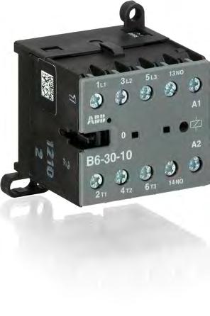
62 B6, B7 -pole mini contactors with screw terminals 4 to 5.5 kw AC operated B CDC211001F0010 Description B6, B7 -pole mini contactors are compact control products mainly used for switching resistive or motor loads up to 690 V AC. These contactors are designed with: main poles and one built-in auxiliary contact control circuit: AC operated low coil consumption (.5 VA at pull-in and at holding) add-on auxiliary contact blocks for front or side mounting and a wide range of accessories hum-free coil designed for rail or wall mounting B Ordering details IEC Rated operational power UL/CSA Rated control circuit voltage U C -phase motor rating 480 V General use rating Auxiliary contacts fitted Catalog number Global code current θ 40 C 400 V 50 Hz 60 Hz AC- AC-1 kw A hp V AC V AC kg Pkg qty Weight (1 pce) B6 mini contactors V / 12 A B GJL R B GJL R B GJL R B GJL R B GJL R B GJL R B GJL R B GJL R B GJL R B GJL R B GJL R B GJL R B7 mini contactors V / 16 A B GJL111001R B GJL111001R B GJL111001R B GJL111001R B GJL111001R B GJL111001R B GJL111001R B GJL111001R B GJL111001R B GJL111001R B GJL111001R B GJL111001R Note: Other types on request Main dimensions mm, inches " " " " " " 2CDC211014F " " 2CDC212001F0011 B6, B7 /4 Motor Protection and Control US Catalog
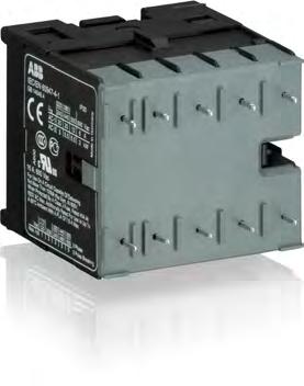
63 BC6, BC7, B7D -pole mini contactors with screw terminals 4 to 5.5 kw DC operated BC CDC211040F0011 Description BC6, BC7, B7D -pole mini contactors are compact control products mainly used for switching resistive or motor loads up to 690 V AC. These contactors are designed with: main poles and one built-in auxiliary contact control circuit: DC operated, low consumption (.5 W at pull-in and at holding) hum-free coil add-on auxiliary contact blocks for front or side mounting and a wide range of accessories designed for rail or wall mounting Ordering details BC CDC21101F0011 IEC UL/CSA Rated control Rated operational circuit voltage power U C -phase motor rating 480 V General use rating Auxiliary contacts fitted Catalog number Global code Pkg qty Weight (1 pce) current θ 40 C 400 V AC- AC-1 kw A hp V DC kg BC6 mini contactors V / 12 A BC GJL121001R BC GJL121001R BC GJL121001R BC GJL121001R BC GJL121001R BC GJL121001R BC GJL121001R BC GJL121001R BC GJL121001R BC GJL121001R BC GJL121001R BC GJL121001R BC7 mini contactors V / 16 A BC GJL11001R BC GJL11001R BC GJL11001R BC GJL11001R BC GJL11001R BC GJL11001R BC GJL11001R BC GJL11001R BC GJL11001R BC GJL11001R BC GJL11001R BC GJL11001R B7D mini contactors with integrated suppressor diode V / B7D GJL117001R A 0 1 B7D GJL117001R B7D GJL117001R B7D GJL117001R Note: Other types on request Main dimensions mm, inches " " " " " " " " 2CDC212001F0011 BC6, BC7, B7D US Catalog Motor Protection and Control /5
64 VB6, VB7 -pole mini reversing contactors with screw terminals 4 to 5.5 kw AC operated Description VB6, VB7 -pole compact design reversing contactors are space optimized control products mainly used for switching resistive or motor loads up to 690 V AC. VB CDC211006F0011 These reversing contactors are designed with: built-in mechanical interlock. The coils must be mutually interlocked electrically and coils must be de-energised for 50 ms at least to prevent phase to phase short circuit on the arc. control circuit: AC operated low coil consumption (.5 VA at pull-in and at holding) hum-free coil add-on auxiliary contact blocks for front mounting designed for rail or wall mounting Ordering details IEC Rated operational power UL/CSA Rated control circuit voltage U C -phase motor rating 480 V General use rating Auxiliary contacts fitted Catalog number Global code Pkg qty current θ 40 C 400 V 50 Hz 60 Hz AC- AC-1 kw A hp V AC V AC kg VB6 mini reversing contactors V / 12 A VB7 mini reversing contactors V / 16 A Note: Other types on request Weight (1 pce) VB GJL R VB GJL R VB GJL R VB GJL R VB GJL R VB GJL R VB GJL R VB GJL R VB GJL R VB GJL R VB GJL R VB GJL R VB GJL111901R VB GJL111901R VB GJL111901R VB GJL111901R VB GJL111901R VB GJL111901R VB GJL111901R VB GJL111901R VB GJL111901R VB GJL111901R VB GJL111901R VB GJL111901R Main dimensions mm, inches " " " " " " " 2CDC212005F0011 VB6, VB7 /6 Motor Protection and Control US Catalog
65 VBC6, VBC7 -pole mini reversing contactors with screw terminals 4 to 5.5 kw DC operated VBC CDC211042F0011 2CDC211001F0011 Description VBC6, VBC7 -pole compact design reversing contactors are space optimized control products mainly used for switching resistive or motor loads up to 690 V AC. These reversing contactors are designed with: built-in mechanical interlock. The coils must be mutually interlocked electrically and coils must be de-energised for 50 ms at least to prevent phase to phase short circuit on the arc. control circuit: DC operated low coil consumption (.5 W at pull-in and at holding) hum-free coil add-on auxiliary contact blocks for front mounting designed for rail or wall mounting Ordering details VBC IEC UL/CSA Rated control Rated operational circuit voltage power U C -phase motor rating 480 V General use rating Auxiliary contacts fitted Catalog number Global code Pkg qty current θ 40 C 400 V AC- AC-1 kw A hp V DC kg Weight (1 pce) VBC6 mini reversing contactors V / 12 A VBC GJL121901R VBC GJL121901R VBC GJL121901R VBC GJL121901R VBC GJL121901R VBC GJL121901R VBC GJL121901R VBC GJL121901R VBC GJL121901R VBC GJL121901R VBC GJL121901R VBC GJL121901R VBC7 mini reversing contactors V / 16 A VBC GJL11901R VBC GJL11901R VBC GJL11901R VBC GJL11901R VBC GJL11901R VBC GJL11901R VBC GJL11901R VBC GJL11901R VBC GJL11901R VBC GJL11901R VBC GJL11901R VBC GJL11901R Note: Other types on request Main dimensions mm, inches " " " " " " " 2CDC212005F0011 VBC6, VBC7 US Catalog Motor Protection and Control /7

66 VB6A, VB7A -pole mini reversing contactors with screw terminals 4 to 5.5 kw AC operated with safety blocking function VB6A CDC21107F0011 2CDC211008F0011 Description VB6A, VB7A -pole compact design reversing contactors are space optimized control products mainly used for switching resistive or motor loads up to 690 V AC. These reversing contactors are designed with: built-in mechanical interlock and safety blocking function. The safety blocking function is triggered if the voltage is applied to the coil of the contactor to be switched on before the contactor to be switched off has dropped out. The contactor coils are designed for continuous operation when the contactor is de-energised i.e. the coil is not damaged if the mechanical interlock prevents switch-on of the contactor with the coil voltage applied. control circuit: AC operated low coil consumption (.5 VA at pull-in and at holding) hum-free coil add-on auxiliary contact blocks for front mounting designed for rail or wall mounting VB7A-0-10 Ordering details IEC UL/CSA Rated control circuit Rated operational voltage power U C -phase motor rating 480 V General use rating Auxiliary contacts fitted Catalog number Global code Pkg qty current θ 40 C 400 V 50 Hz 60 Hz AC- AC-1 kw A hp V AC V AC kg Weight (1 pce) VB6A mini reversing contactors with safety blocking function V / VB6A GJL R A 0 1 VB6A GJL R VB6A GJL R VB6A GJL R VB6A GJL R VB6A GJL R VB6A GJL R VB6A GJL R VB6A GJL R VB6A GJL R VB6A GJL R VB6A GJL R VB7A mini reversing contactors with safety blocking function V / VB7A GJL111911R A 0 1 VB7A GJL111911R VB7A GJL111911R VB7A GJL111911R VB7A GJL111911R VB7A GJL111911R VB7A GJL111911R VB7A GJL111911R VB7A GJL111911R VB7A GJL111911R VB7A GJL111911R VB7A GJL111911R Note: Other types on request Main dimensions mm, inches " " " " " " VB6A, VB7A " 2CDC212005F0011 /8 Motor Protection and Control US Catalog
67 VBC6A, VBC7A -pole mini reversing contactors with screw terminals 4 to 5.5 kw DC operated with safety blocking function VBC6A CDC211044F0011 2CDC211007F0011 Description VBC6A, VBC7A -pole compact design reversing contactors are space optimized control products mainly used for switching resistive or motor loads up to 690 V AC. These reversing contactors are designed with: built-in mechanical interlock and safety blocking function. The safety blocking function is triggered if the voltage is applied to the coil of the contactor to be switched on before the contactor to be switched off has dropped out. The contactor coils are designed for continuous operation when the contactor is de-energised i.e. the coil is not damaged if the mechanical interlock prevents switch-on of the contactor with the coil voltage applied. control circuit: DC operated low coil consumption (.5 W at pull-in and at holding) hum-free coil add-on auxiliary contact blocks for front mounting designed for rail or wall mounting VBC7A-0-10 Ordering details IEC UL/CSA Rated control Rated operational circuit voltage power U C -phase motor rating 480 V General use rating Auxiliary contacts fitted Catalog number Global code Pkg qty current θ 40 C 400 V AC- AC-1 kw A hp V DC kg Weight (1 pce) VBC6A mini reversing contactors with safety blocking function V / VBC6A GJL121911R A 0 1 VBC6A GJL121911R VBC6A GJL121911R VBC6A GJL121911R VBC6A GJL121911R VBC6A GJL121911R VBC6A GJL121911R VBC6A GJL121911R VBC6A GJL121911R VBC6A GJL121911R VBC6A GJL121911R VBC6A GJL121911R VBC7A mini reversing contactors with safety blocking function V / VBC7A GJL11911R A 0 1 VBC7A GJL11911R VBC7A GJL11911R VBC7A GJL11911R VBC7A GJL11911R VBC7A GJL11911R VBC7A GJL11911R VBC7A GJL11911R VBC7A GJL11911R VBC7A GJL11911R VBC7A GJL11911R VBC7A GJL11911R Note: Other types on request Main dimensions mm, inches " " " " " " " 2CDC212005F0011 VBC6A, VBC7A US Catalog Motor Protection and Control /9
68 BC6, BC7 -pole interface mini contactors with screw terminals 4 to 5.5 kw DC operated BC CDC211040F0011 Description BC6, BC7 -pole interface mini contactors are compact control products mainly used for switching resistive or motor loads up to 690 V AC. These contactors are designed with: main poles and one built-in auxiliary contact control circuit: DC operated, very low coil consumption. Suitable for direct control by PLC outputs hum-free coil no auxiliary contact block permitted for mounting designed for rail or wall mounting BC Ordering details IEC Rated operational power UL/CSA Rated control circuit voltage U C -phase motor rating 480 V General use rating Auxiliary contacts fitted Catalog number Global code Pkg qty current θ 40 C 400 V AC- AC-1 kw A hp V DC kg Weight (1 pce) DC operation 24 V / 1.4 W V / 12 A V / 16 A DC operation 17 2 V / 2.4 W V / 12 A V / 16 A BC GJL121001R BC GJL121001R BC GJL11001R BC GJL11001R BC GJL121001R BC GJL121001R BC GJL11001R BC GJL11001R Connection to PLCs with integrated protective circuit DC operation 24 V / 1.7 W V / 12 A V / 16 A DC operation 17 2 V / 2.8 W V / 12 A V / 16 A B6S GJL121001R B6S GJL121001R B7S GJL11001R B7S GJL11001R B6S GJL121001R B6S GJL121001R B7S GJL11001R B7S GJL11001R Note: Other types on request Main dimensions mm, inches " " " " " " " 2CDC21101F " 2CDC212001F0011 BC6, BC7 /10 Motor Protection and Control US Catalog
69 TBC7 -pole mini contactors with screw terminals 4 to 5.5 kw DC operated large coil voltage range TBC CDC211015F0011 Description TBC7 -pole mini contactors are compact control products mainly used for switching resistive or motor loads up to 690 V AC. These contactors are designed with: main poles and one built-in auxiliary contact control circuit: DC operated low coil consumption (5 W at pull-in and at holding) hum-free coil expanded ambient temperature range C and wide range voltage supply no auxiliary contact block permitted for mounting designed for rail or wall mounting material is approved for railway applications Ordering details IEC UL/CSA Rated control Rated operational circuit voltage power U Cmin... U Cmax -phase motor rating 480 V General use rating Auxiliary contacts fitted Catalog number Global code Pkg qty current θ 40 C 400 V AC- AC-1 kw A hp V DC kg Weight (1 pce) TBC7 mini contactors V / 16 A TBC GJL11061R TBC GJL11061R TBC GJL11061R TBC GJL11061R TBC GJL11061R TBC GJL11061R TBC GJL11061R TBC GJL11061R Note: Other types on request Main dimensions mm, inches " " " " " " " " 2CDC212001F0011 TBC7 US Catalog Motor Protection and Control /11
70 B6, B7 4-pole mini contactors with screw terminals 4 to 5.5 kw AC operated B CDC211028F0011 Description B6, B7 4-pole mini contactors are compact control products mainly used for switching resistive loads up to 690 V AC. These contactors are designed with: 4 main poles control circuit: AC operated low coil consumption (.5 VA at pull-in and at holding) add-on auxiliary contact blocks for front or side mounting and a wide range of accessories hum-free coil designed for rail or wall mounting Ordering details IEC UL/CSA Rated control Rated operational General use circuit voltage current rating U C θ 40 C 50/60 Hz AC-1 Auxiliary contacts fitted Catalog number Global code Pkg qty Weight (1 pce) A V AC kg 4 N.O. main poles V / 12 A B GJL R B GJL R B GJL R B GJL R B GJL R V / 16 A B GJL111201R B GJL111201R B GJL111201R B GJL111201R B GJL111201R N.O. + 2 N.C. main poles V / 12 A B GJL R B GJL R B GJL R B GJL R B GJL R V / 16 A B GJL111501R B GJL111501R B GJL111501R B GJL111501R B GJL111501R Note: Other types on request Main dimensions mm, inches " " " " " " " " 2CDC212001F0011 B6, B7 /12 Motor Protection and Control US Catalog
71 BC6, B7D 4-pole mini contactors with screw terminals 4 to 5.5 kw DC operated BC CDC21102F0011 Description BC6, B7D 4-pole mini contactors are compact control products mainly used for switching resistive loads up to 690 V AC. These contactors are designed with: 4 main poles control circuit: DC operated low coil consumption (.5 W at pull-in and at holding) hum-free coil add-on auxiliary contact blocks for front or side mounting designed for rail or wall mounting Ordering details IEC UL/CSA Rated control Rated General use circuit voltage operational rating U C Auxiliary contacts fitted Catalog number Global code Pkg qty current θ 40 C AC-1 A V DC kg Weight (1 pce) 4 N.O. main poles V / 16 A B7D GJL117201R B7D GJL117201R N.O. + 2 N.C. main poles V / 12 A BC GJL121501R BC GJL121501R BC GJL121501R BC GJL121501R BC GJL121501R BC GJL121501R BC GJL121501R Note: Other types on request Main dimensions mm, inches " " " " " " " " 2CDC212001F0011 BC6, B7D US Catalog Motor Protection and Control /1

72 TBC7 4-pole mini contactors with screw terminals 4 to 5.5 kw DC operated large coil voltage range TBC CDC211026F0011 Description TBC7 4-pole mini contactors are compact control products mainly used for switching resistive or motor loads up to 690 V AC. These contactors are designed with: 4 main poles control circuit: DC operated low coil consumption (5 W at pull-in and at holding) hum-free coil expanded ambient temperature range C and wide range voltage supply no auxiliary contact block permitted for mounting designed for rail or wall mounting material is approved for railway applications Ordering details IEC UL/CSA Rated control Rated operational General use circuit voltage current rating U C min... U C max θ 40 C AC-1 Auxiliary contacts fitted Catalog number Global code Pkg qty A V DC kg Weight (1 pce) N.O. + 1 N.C. main poles V / 16 A TBC GJL11461R TBC GJL11461R TBC GJL11461R N.O. + 2 N.C. main poles V / 16 A TBC GJL11561R TBC GJL11561R TBC GJL11561R Note: Other types on request Main dimensions mm, inches " " " " " " " " 2CDC212001F0011 TBC7 /14 Motor Protection and Control US Catalog

73 K6 4-pole mini contactor relays with screw terminals AC operated K6-22Z 2CDC211012F0011 Description K6 4-pole mini-contactor relays are space optimized control products mainly used for control functions or for small loads up to 4 A. These contactors are designed with: 4-poles with various contact combinations control circuit: AC operated low coil consumption (.5 VA at pull-in and at holding) hum-free coil add-on auxiliary contact blocks for front or side mounting designed for rail or wall mounting 2CDC211004F0010 Ordering details Rated control circuit voltage Catalog number Global code Pkg U C qty Weight (1 pce) 50 Hz 60 Hz K6-1Z V AC V AC kg K6 4-pole mini contactor relays K6-22Z-01 GJH R K6-22Z-02 GJH R K6-22Z-0 GJH R K6-22Z-84 GJH R K6-22Z-80 GJH R K6-22Z-85 GJH R K6-1Z-01 GJH R K6-1Z-02 GJH R K6-1Z-0 GJH R K6-1Z-84 GJH R K6-1Z-80 GJH R K6-1Z-85 GJH R K6-40E-01 GJH R K6-40E-02 GJH R K6-40E-0 GJH R K6-40E-84 GJH R K6-40E-80 GJH R K6-40E-85 GJH R Note: Other types on request Main dimensions mm, inches " " " " " " " " 2CDC212001F0011 K6 US Catalog Motor Protection and Control /15
74 KC6 4-pole mini contactor relays with screw terminals DC operated KC6-22Z 2CDC211016F0011 Description KC6 4-pole mini-contactor relays are space optimized control products mainly used for control functions or for small loads up to 4 A. These contactors are designed with: 4-poles with various contact combinations control circuit: DC operated low coil consumption (.5 W at pull-in and at holding) hum-free coil add-on auxiliary contact blocks for front or side mounting designed for rail or wall mounting Ordering details Rated control circuit voltage Catalog number Global code Pkg U C qty V DC Weight (1 pce) kg KC6 4-pole mini contactor relays 12 KC6-22Z-07 GJH121001R KC6-22Z-01 GJH121001R KC6-22Z-16 GJH121001R KC6-22Z-0 GJH121001R KC6-22Z-04 GJH121001R KC6-22Z-05 GJH121001R KC6-1Z-07 GJH121001R KC6-1Z-01 GJH121001R KC6-1Z-16 GJH121001R KC6-1Z-0 GJH121001R KC6-1Z-04 GJH121001R KC6-1Z-05 GJH121001R KC6-40E-07 GJH121001R KC6-40E-01 GJH121001R KC6-40E-16 GJH121001R KC6-40E-0 GJH121001R KC6-40E-04 GJH121001R KC6-40E-05 GJH121001R Note: Other types on request Main dimensions mm, inches " " " " " " " " 2CDC212001F0011 KC6 /16 Motor Protection and Control US Catalog

75 KC6 4-pole interface mini contactor relays with screw terminals DC operated KC6-1Z 2CDC211017F0011 Description KC6 4-pole interface mini-contactor relays are space optimized control products mainly used for control functions or for small loads up to 4 A. These contactors are designed with: 4-poles with various contact combinations control circuit: DC operated low coil consumption ( W at pull-in and at holding) hum-free coil no auxiliary contact block permitted for mounting designed for rail or wall mounting Ordering details Rated control circuit voltage Catalog number Global code Pkg U C qty V DC Weight (1 pce) DC operation 24 V / 1.4 W 24 KC6-1Z-1.4 GJH121001R KC6-40E-1.4 GJH121001R kg DC operation V / 2.4 W KC6-1Z-2.4 GJH121001R KC6-40E-2.4 GJH121001R DC operation 24 V / 1.7 W 24 K6S-22Z-1.7 GJH121001R K6S-1Z-1.7 GJH121001R K6S-40E-1.7 GJH121001R DC operation V / 2.8 W K6S-22Z-2.8 GJH121001R K6S-1Z-2.8 GJH121001R K6S-40E-2.8 GJH121001R Note: Other types on request Main dimensions mm, inches " " " " " " " " 2CDC212001F0011 KC6 US Catalog Motor Protection and Control /17
76 TKC6 4-pole mini contactor relays with screw terminals DC operated large coil voltage range TKC6-1Z 2CDC211021F0011 Description TKC6 4-pole mini contactors are space optimized control products mainly used for control functions or for small loads up to 4 A. These contactors are designed with: 4-poles with various contact combinations control circuit: DC operated, hum free, low consumption (5 W at pull-in and at holding) expanded ambient temperature range C and wide range voltage supply material is suitable for railway applications humfree operating DC coil no auxiliary contact block permitted for mounting designed for rail or wall mounting Ordering details Rated control circuit voltage Catalog number Global code Pkg U C min... U C max qty V DC Weight (1 pce) kg TKC6-22Z-51 GJH121061R TKC6-22Z-55 GJH121061R TKC6-22Z-62 GJH121061R TKC6-22Z-68 GJH121061R TKC6-1Z-51 GJH121061R TKC6-1Z-55 GJH121061R TKC6-1Z-62 GJH121061R TKC6-1Z-68 GJH121061R TKC6-40E-51 GJH121061R TKC6-40E-55 GJH121061R TKC6-40E-62 GJH121061R TKC6-40E-68 GJH121061R Note: Other types on request Main dimensions mm, inches " " " " " " " " 2CDC212001F0011 TKC6 /18 Motor Protection and Control US Catalog

77 B6, B7 -pole mini contactors with soldering pins 4 to 5.5 kw AC operated B P 2CDC21100F0010 Description B6..P and B7..P -pole mini contactors are compact control products mainly used for switching resistive or motor loads up to 690 V AC. These contactors are designed with: main poles and one built-in auxiliary contact control circuit: AC operated low coil consumption (.5 VA at pull-in and at holding) hum-free coil add-on auxiliary contact blocks for side mounting designed for soldering on PCB boards B P 2CDC211011F0011 Ordering details IEC Rated operational power UL/CSA Rated control circuit voltage U C -phase motor rating 480 V General use rating Auxiliary contacts fitted Catalog number Global code Pkg qty current θ 40 C 400 V 50 Hz 60 Hz AC- AC-1 kw A hp V AC V AC kg Weight (1 pce) B6 mini contactors V / 12 A B P01 GJL R B P01 GJL R B P02 GJL R B P02 GJL R B P0 GJL R B P0 GJL R B P84 GJL R B P84 GJL R B P80 GJL R B P80 GJL R B P85 GJL R B P85 GJL R B7 mini contactors V / 16 A B P01 GJL111009R B P01 GJL111009R B P02 GJL111009R B P02 GJL111009R B P0 GJL111009R B P0 GJL111009R B P84 GJL111009R B P84 GJL111009R B P80 GJL111009R B P80 GJL111009R B P85 GJL111009R B P85 GJL111009R Note: Other types on request Main dimensions mm, inches " " " " " " " 2CDC21200F0011 B6, B7 US Catalog Motor Protection and Control /19
78 BC6, BC7 -pole mini contactors with soldering pins 4 to 5.5 kw DC operated BC P 2CDC21100F0011 Description BC6, BC7 -pole mini contactors are compact control products mainly used for switching resistive or motor loads up to 690 V AC. These contactors are designed with: main poles and one built-in auxiliary contact control circuit: DC operated low coil consumption (.5 W at pull-in and at holding) hum-free coil add-on auxiliary contact blocks for side mounting designed for soldering on PCB boards Ordering details IEC UL/CSA Rated control Rated operational circuit voltage power U C -phase motor rating 480 V General use rating Auxiliary contacts fitted Catalog number Global code Pkg qty current θ 40 C 400 V AC- AC-1 kw A hp V DC kg Weight (1 pce) BC6 mini contactors with N.O. main poles V / BC P07 GJL121009R A 0 1 BC P07 GJL121009R BC P01 GJL121009R BC P01 GJL121009R BC P16 GJL121009R BC P16 GJL121009R BC P0 GJL121009R BC P0 GJL121009R BC P04 GJL121009R BC P04 GJL121009R BC P05 GJL121009R BC P05 GJL121009R BC7 mini contactors with N.O. main poles V / BC P07 GJL11009R A 0 1 BC P07 GJL11009R BC P01 GJL11009R BC P01 GJL11009R BC P16 GJL11009R BC P16 GJL11009R BC P0 GJL11009R BC P0 GJL11009R BC P04 GJL11009R BC P04 GJL11009R BC P05 GJL11009R BC P05 GJL11009R BC6 mini contactors 2 N.O. + 1 N.C. main poles V / BC P01 GJL121109R A BC P16 GJL121109R BC P0 GJL121109R BC P04 GJL121109R BC P05 GJL121109R Note: Other types on request Main dimensions mm, inches " " " " " " " 2CDC21200F0011 B6, B7 /20 Motor Protection and Control US Catalog


79 VB6, VB7 -pole mini reversing contactors with soldering pins 4 to 5.5 kw AC operated Description VB6, VB7 -pole compact design reversing contactors are space optimized control products mainly used for switching resistive or motor loads up to 690 V AC. VB P These reversing contactors are designed with: built-in mechanical interlock. The coils must be mutually interlocked electrically and coils must be de-energised for 50 ms at least to prevent phase to phase short circuit on the arc control circuit: AC operated low coil consumption (.5 VA at pull-in and at holding) hum-free coil no auxiliary contact block permitted for mounting designed for soldering on PCB boards Ordering details IEC Rated operational power UL/CSA Rated control circuit voltage U C -phase motor rating 480 V General use rating Auxiliary contacts fitted Catalog number Global code Pkg qty current θ 40 C 400 V 50 Hz 60 Hz AC- AC-1 kw A hp V AC V AC kg VB6 mini reversing contactors V / 12 A VB7 mini reversing contactors V / 16 A Note: Other types on request Weight (1 pce) VB P01 GJL R VB P01 GJL R VB P02 GJL R VB P02 GJL R VB P0 GJL R VB P0 GJL R VB P84 GJL R VB P84 GJL R VB P80 GJL R VB P80 GJL R VB P85 GJL R VB P85 GJL R VB P01 GJL111909R VB P01 GJL111909R VB P02 GJL111909R VB P02 GJL111909R VB P0 GJL111909R VB P0 GJL111909R VB P84 GJL111909R VB P84 GJL111909R VB P80 GJL111909R VB P80 GJL111909R VB P85 GJL111909R VB P85 GJL111909R Main dimensions mm, inches " " " " " " " " 2CDC211010S " 2CDC212007F0011 VB6, VB7 US Catalog Motor Protection and Control /21
80 VBC6, VBC7 -pole mini reversing contactors with soldering pins 4 to 5.5 kw DC operated VBC P 2CDC211009F0011 Description VBC6, VBC7 -pole compact design reversing contactors are space optimized control products mainly used for switching resistive or motor loads up to 690 V AC. These reversing contactors are designed with: built-in mechanical interlock. The coils must be mutually interlocked electrically and coils must be de-energised for 50 ms at least to prevent phase to phase short circuit on the arc control circuit: DC operated low coil consumption (.5 W at pull-in and at holding) hum-free coil no auxiliary contact block permitted for mounting designed for soldering on PCB boards Ordering details IEC UL/CSA Rated control Rated operational circuit voltage power U C -phase motor rating 480 V General use rating Auxiliary contacts fitted Catalog number Global code Pkg qty current θ 40 C 400 V AC- AC-1 kw A hp V DC kg Weight (1 pce) VBC6 mini reversing contactors V / 12 A VBC P07 GJL121909R VBC P07 GJL121909R VBC P01 GJL121909R VBC P01 GJL121909R VBC P06 GJL121909R VBC P06 GJL121909R VBC P0 GJL121909R VBC P0 GJL121909R VBC P04 GJL121909R VBC P04 GJL121909R VBC P05 GJL121909R VBC P05 GJL121909R VBC7 mini reversing contactors V / 16 A VBC P07 GJL11909R VBC P07 GJL11909R VBC P01 GJL11909R VBC P01 GJL11909R VBC P16 GJL11909R VBC P16 GJL11909R VBC P0 GJL11909R VBC P0 GJL11909R VBC P04 GJL11909R VBC P04 GJL11909R VBC P05 GJL11909R VBC P05 GJL11909R Note: Other types on request Main dimensions mm, inches " " " " " " " " " 2CDC212007F0011 VBC6, VBC7 /22 Motor Protection and Control US Catalog
81 VB6A, VB7A -pole mini reversing contactors with soldering pins 4 to 5.5 kw AC operated with safety blocking function VB P 2CDC21101F0010 Description VB6A, VB7A -pole compact design reversing contactors are space optimized control products mainly used for switching resistive or motor loads up to 690 V AC. These reversing contactors are designed with: built-in mechanical interlock and safety blocking function. The safety blocking function is triggered if the voltage is applied to the coil of the contactor to be switched on before the contactor to be switched off has dropped out. The contactor coils are designed for continuous operation when the contactor is de-energised i.e. the coil is not damaged if the mechanical interlock prevents switch-on of the contactor with the coil voltage applied. control circuit: AC operated low coil consumption (.5 VA at pull-in and at holding) hum-free coil no auxiliary contact block permitted for mounting designed for soldering on PCB boards Ordering details IEC UL/CSA Rated control circuit Rated operational voltage power U C -phase motor rating 480 V General use rating Auxiliary contacts fitted Catalog number Global code Pkg qty current θ 40 C 400 V 50 Hz 60 Hz AC- AC-1 kw A hp V AC V AC kg Weight (1 pce) VB6A mini reversing contactors with safety blocking function V / VB6A-0-10-P01 GJL R A 0 1 VB6A-0-01-P01 GJL R VB6A-0-10-P02 GJL R VB6A-0-01-P02 GJL R VB6A-0-10-P0 GJL R VB6A-0-01-P0 GJL R VB6A-0-10-P84 GJL R VB6A-0-01-P84 GJL R VB6A-0-10-P80 GJL R VB6A-0-01-P80 GJL R VB6A-0-10-P85 GJL R VB6A-0-01-P85 GJL R VB7A mini reversing contactors with safety blocking function V / VB7A-0-10-P01 GJL111919R A 0 1 VB7A-0-01-P01 GJL111919R VB7A-0-10-P02 GJL111919R VB7A-0-01-P02 GJL111919R VB7A-0-10-P0 GJL111919R VB7A-0-01-P0 GJL111919R VB7A-0-10-P84 GJL111919R VB7A-0-01-P84 GJL111919R VB7A-0-10-P80 GJL111919R VB7A-0-01-P80 GJL111919R VB7A-0-10-P85 GJL111919R VB7A-0-01-P85 GJL111919R Note: Other types on request Main dimensions mm, inches " " " " " " " " " 2CDC212007F0011 VB6A, VB7A US Catalog Motor Protection and Control /2
82 VBC7A -pole mini reversing contactors with soldering pins 4 to 5.5 kw DC operated with safety blocking function VBC7A-0-10-P 2CDC211009F0011 Description VBC7A -pole compact design reversing contactors are space optimized control products mainly used for switching resistive or motor loads up to 690 V AC. These reversing contactors are designed with: built-in mechanical interlock and safety blocking function. The safety blocking function is triggered if the voltage is applied to the coil of the contactor to be switched on before the contactor to be switched off has dropped out. The contactor coils are designed for continuous operation when the contactor is de-energised i.e. the coil is not damaged if the mechanical interlock prevents switch-on of the contactor with the coil voltage applied. control circuit: AC operated low coil consumption (.5 W at pull-in and at holding) hum-free coil no auxiliary contact block permitted for mounting designed for soldering on PCB boards Ordering details IEC UL/CSA Rated control Rated operational circuit voltage power U C -phase motor rating 480 V General use rating Auxiliary contacts fitted Catalog number Global code Pkg qty current θ 40 C 400 V AC- AC-1 kw A hp V DC kg Weight (1 pce) VBC7A mini reversing contactors with safety blocking function V / VBC7A-0-10-P07 GJL11919R A 0 1 VBC7A-0-01-P07 GJL11919R VBC7A-0-10-P01 GJL11919R VBC7A-0-01-P01 GJL11919R VBC7A-0-10-P16 GJL11919R VBC7A-0-01-P16 GJL11919R VBC7A-0-10-P0 GJL11919R VBC7A-0-01-P0 GJL11919R VBC7A-0-10-P04 GJL11919R VBC7A-0-01-P04 GJL11919R VBC7A-0-10-P05 GJL11919R VBC7A-0-01-P05 GJL11919R Note: Other types on request Main dimensions mm, inches " " " " " " " " " 2CDC212007F0011 VBC7A /24 Motor Protection and Control US Catalog
83 K6 4-pole mini contactor relays with soldering pins AC operated K6-22Z-P 2CDC211022F0011 Description K6 4-pole mini-contactor relays are space optimized control products mainly used for control functions or for small loads up to 4 A. These contactors are designed with: 4-poles with various contact combinations control circuit: AC operated low coil consumption (.5 VA at pull-in and at holding) hum-free coil add-on auxiliary contact block for side mounting designed for soldering on PCB boards Ordering details Rated control circuit voltage Catalog number Global code Pkg U C qty 50 Hz V AC 60 Hz V AC Weight (1 pce) kg K6 4-pole mini contactor relays K6-22Z-P01 GJH R K6-22Z-P02 GJH R K6-22Z-P0 GJH R K6-22Z-P84 GJH R K6-22Z-P80 GJH R K6-22Z-P85 GJH R K6-1Z-P01 GJH R K6-1Z-P02 GJH R K6-1Z-P0 GJH R K6-1Z-P84 GJH R K6-1Z-P80 GJH R K6-1Z-P85 GJH R K6-40E-P01 GJH R K6-40E-P02 GJH R K6-40E-P0 GJH R K6-40E-P84 GJH R K6-40E-P80 GJH R K6-40E-P85 GJH R Note: Other types on request Main dimensions mm, inches " " " " " " " 2CDC21200F0011 K6 US Catalog Motor Protection and Control /25

84 KC6 4-pole mini contactor relays with soldering pins DC operated KC6-22Z-P 2CDC211025F0011 Description KC6 4-pole mini-contactor relays are space optimized control products mainly used for control functions or for small loads up to 4 A. These contactors are designed with: 4-poles with various contact combinations control circuit: DC operated low coil consumption (.5 W at pull-in and at holding) hum-free coil add-on auxiliary contact block for side mounting designed for soldering on PCB boards Ordering details Rated control circuit voltage U C Catalog number Global code Pkg qty V DC Weight (1 pce) kg K6 4-pole mini contactor relays 12 KC6-22Z-P07 GJH121009R KC6-22Z-P01 GJH121009R KC6-22Z-P16 GJH121009R KC6-22Z-P04 GJH121009R KC6-22Z-P05 GJH121009R KC6-1Z-P01 GJH121009R KC6-1Z-P16 GJH121009R KC6-1Z-P04 GJH121009R KC6-1Z-P05 GJH121009R KC6-40E-P07 GJH121009R KC6-40E-P01 GJH121009R KC6-40E-P16 GJH121009R KC6-40E-P04 GJH121009R KC6-40E-P05 GJH121009R Note: Other types on request Main dimensions mm, inches " " " " " " " 2CDC21102F0011 2CDC21200F0011 KC6-1Z-P KC6 /26 Motor Protection and Control US Catalog
85 BC6, BC7 -pole interface mini contactors with soldering pins 4 to 5.5 kw DC operated BC P 2CDC21100F0011 Description BC6, BC7 -pole interface mini contactors are compact control products mainly used for switching resistive or motor loads up to 690 V AC. These contactors are designed with: main poles and one built-in auxiliary contact control circuit: DC operated low coil consumption ( W at pull-in and at holding) hum-free coil no auxiliary contact block permitted for mounting designed for soldering on PCB boards Ordering details IEC UL/CSA Rated control Rated operational circuit voltage power U C -phase motor rating 480 V General use rating Auxiliary contacts fitted Catalog number Global code Pkg qty current θ 40 C 400 V AC- AC-1 kw A hp V DC kg Weight (1 pce) DC operation 24 V / 1.4 W V / 12 A V / 16 A BC P1.4 GJL121009R BC P1.4 GJL121009R BC P1.4 GJL11009R BC P1.4 GJL11009R DC operation 17 2 V / 2.4 W, I th < 8 A V / 12 A V / 16 A BC P2.4 GJL121009R BC P2.4 GJL121009R BC P2.4 GJL11009R BC P2.4 GJL11009R Note: Other types on request Main dimensions mm, inches " " " " " " " 2CDC21200F0011 BC6, BC7 US Catalog Motor Protection and Control /27

86 KC6 4-pole interface mini contactor relays with solderings pins DC operated KC6-1Z-P-1.4 2CDC21102F0011 Description KC6 4-pole interface mini-contactor relays are space optimized control products mainly used for control functions or for small loads up to 4 A. These contactors are designed with: 4-poles with various contact combinations control circuit: DC operated low coil consumption (.5 W at pull-in and at holding) hum-free coil add-on auxiliary contact block for side mounting designed for soldering on PCB boards Ordering details Rated control circuit voltage Catalog number Global code Pkg U C qty V DC Weight (1 pce) kg DC operation 24 V / 1.4 W 24 KC6-1Z-P1.4 GJH121009R KC6-40E-P1.4 GJH121009R DC operation V / 2.4 W KC6-1Z-P2.4 GJH121009R KC6-40E-P2.4 GJH121009R Note: Other types on request Main dimensions mm, inches " " " " " " " 2CDC21200F0011 KC6 /28 Motor Protection and Control US Catalog
87 B6, B7 -pole mini contactors with flat pin connection 4 to 5.5 kw AC operated B F 2CDC211002F0010 Description B6..F, B7..F -pole mini contactors are compact control products mainly used for switching resistive or motor loads up to 690 V AC. These contactors are designed with: flat pin connection for plug-in wiring and shake proven connection main poles and one built-in auxiliary contact control circuit: AC operated low coil consumption (.5 VA at pull-in and at holding) hum-free coil add-on auxiliary contact blocks for side mounting designed for rail or wall mounting B F 2CDC21101F0011 Ordering details IEC Rated operational power UL/CSA Rated control circuit voltage U C -phase motor rating 480 V General use rating Auxiliary contacts fitted Catalog number Global code Pkg qty current θ 40 C 400 V 50 Hz 60 Hz AC- AC-1 kw A hp V AC V AC kg Weight (1 pce) B6 mini contactors V / 12 A B F01 GJL121100R B F01 GJL121100R B F02 GJL121100R B F02 GJL121100R B F0 GJL121100R B F0 GJL121100R B F84 GJL121100R B F84 GJL121100R B F80 GJL121100R B F80 GJL121100R B F85 GJL121100R B F85 GJL121100R B7 mini contactors V / 16 A B F01 GJL11100R B F01 GJL11100R B F02 GJL11100R B F02 GJL11100R B F0 GJL11100R B F0 GJL11100R B F84 GJL11100R B F84 GJL11100R B F80 GJL11100R B F80 GJL11100R B F85 GJL11100R B F85 GJL11100R Note: Other types on request Main dimensions mm, inches " " " " " " " B6, B " 2CDC212002F0011 US Catalog Motor Protection and Control /29
88 BC6, BC7 -pole mini contactors with flat pin connection 4 to 5.5 kw DC operated BC F BC F 2CDC211041F0011 2CDC211024F0011 Description BC6, BC7 -pole mini contactors are compact control products mainly used for switching resistive or motor loads up to 690 V AC. These contactors are designed with: flat pin connection for plug-in wiring and shake proven connection main poles and one built-in auxiliary contact control circuit: DC operated low coil consumption (.5 W at pull-in and at holding) hum-free coil add-on auxiliary contact blocks for side mounting designed for rail or wall mounting Ordering details IEC UL/CSA Rated control Rated operational circuit voltage power U C -phase motor rating 480 V General use rating Auxiliary Catalog number Order code Pkg contacts qty fitted current θ 40 C 400 V AC- AC-1 kw A hp V DC kg Weight (1 pce) BC6 mini contactors V / 12 A BC F07 GJL12100R BC F07 GJL12100R BC F01 GJL12100R BC F01 GJL12100R BC F16 GJL12100R BC F16 GJL12100R BC F0 GJL12100R BC F0 GJL12100R BC F04 GJL12100R BC F04 GJL12100R BC F05 GJL12100R BC F05 GJL12100R BC7 mini contactors V / 16 A BC F07 GJL1100R BC F07 GJL1100R BC F01 GJL1100R BC F01 GJL1100R BC F16 GJL1100R BC F16 GJL1100R BC F0 GJL1100R BC F0 GJL1100R BC F04 GJL1100R BC F04 GJL1100R BC F05 GJL1100R BC F05 GJL1100R Other types on request Main dimensions mm, inches " " " " " " " " 2CDC212002F0011 /0 Motor Protection and Control US Catalog BC6, BC7
89 VB7 -pole mini reversing contactors with flat pin connection 4 to 5.5 kw AC operated VB F 2CDC211005F0011 Description VB7 -pole compact design reversing contactors are space optimized control products mainly used for switching resistive or motor loads up to 690 V AC. These reversing contactors are designed with: built-in mechanical interlock. The coils must be mutually interlocked electrically and coils must be de-energised for 50 ms at least to prevent phase to phase short circuit on the arc. flat pin connection for plug-in wiring and shake proven connection control circuit: AC operated low coil consumption (.5 VA at pull-in and at holding) hum-free coil no auxiliary contact block permitted for mounting for rail and wall mounting Ordering details IEC UL/CSA Rated control circuit Rated operational voltage power U C -phase motor rating 480 V General use rating Auxiliary contacts fitted Catalog number Global code Pkg qty current θ 40 C 400 V 50 Hz 60 Hz AC- AC-1 kw A hp V AC V AC kg Weight (1 pce) VB7 mini reversing contactors V / 16 A VB F01 GJL11190R VB F01 GJL11190R VB F02 GJL11190R VB F02 GJL11190R VB F0 GJL11190R VB F0 GJL11190R VB F84 GJL11190R VB F84 GJL11190R VB F80 GJL11190R VB F80 GJL11190R VB F85 GJL11190R VB F85 GJL11190R Note: Other types on request Main dimensions mm, inches " " " " " " " 2CDC212006F0011 VB7 US Catalog Motor Protection and Control /1
90 VBC7 -pole mini reversing contactors with flat pin connection 4 to 5.5 kw DC operated VBC F 2CDC211004F0011 Description VBC7 -pole compact design reversing contactors are space optimized control products mainly used for switching resistive or motor loads up to 690 V AC. These reversing contactors are designed with: built-in mechanical interlock. The coils must be mutually interlocked electrically and coils must be de-energised for 50 ms at least to prevent phase to phase short circuit on the arc flat pin connection for plug-in wiring and shake proven connection control circuit: DC operated low coil consumption (.5 W at pull-in and at holding) hum-free coil no auxiliary contact block permitted for mounting for rail and wall mounting Ordering details IEC UL/CSA Rated control Rated operational circuit voltage power U C -phase motor rating 480 V General use rating Auxiliary contacts fitted Catalog number Global code Pkg qty current θ 40 C 400 V AC- AC-1 kw A hp V DC kg Weight (1 pce) VBC7 mini reversing contactors V / 16 A VBC F07 GJL1190R VBC F07 GJL1190R VBC F01 GJL1190R VBC F01 GJL1190R VBC F16 GJL1190R VBC F16 GJL1190R VBC F0 GJL1190R VBC F0 GJL1190R VBC F04 GJL1190R VBC F04 GJL1190R VBC F05 GJL1190R VBC F05 GJL1190R Note: Other types on request Main dimensions mm, inches " " " " " " " 2CDC212006F0011 VBC7 /2 Motor Protection and Control US Catalog
91 VB7A -pole mini reversing contactors with flat pin connection 4 to 5.5 kw AC operated with safety blocking function VB7A-0-10-F 2CDC21100F0011 Description VB7A -pole compact design reversing contactors are space optimized control products mainly used for switching resistive or motor loads up to 690 V AC. These reversing contactors are designed with: built-in mechanical interlock and safety blocking function. The safety blocking function is triggered if the voltage is applied to the coil of the contactor to be switched on before the contactor to be switched off has dropped out. The contactor coils are designed for continuous operation when the contactor is de-energised i.e. the coil is not damaged if the mechanical interlock prevents switch-on of the contactor with the coil voltage applied. flat pin connection for plug-in wiring and shake proven connection control circuit: AC operated low coil consumption (.5 VA at pull-in and at holding) hum-free coil no auxiliary contact block permitted for mounting for rail and wall mounting Ordering details IEC UL/CSA Rated control circuit Rated operational voltage power U C -phase motor rating 480 V General use rating Auxiliary contacts fitted Catalog number Global code Pkg qty current θ 40 C 400 V 50 Hz 60 Hz AC- AC-1 kw A hp V AC V AC pce kg Weight (1 pce) VB7A mini reversing contactors with safety blocking function V / VB7A-0-10-F01 GJL11191R A 0 1 VB7A-0-01-F01 GJL11191R VB7A-0-10-F02 GJL11191R VB7A-0-01-F02 GJL11191R VB7A-0-10-F0 GJL11191R VB7A-0-01-F0 GJL11191R VB7A-0-10-F84 GJL11191R VB7A-0-01-F84 GJL11191R VB7A-0-10-F80 GJL11191R VB7A-0-01-F80 GJL11191R VB7A-0-10-F85 GJL11191R VB7A-0-01-F85 GJL11191R Note: Other types on request Main dimensions mm, inches " " " " " " " 2CDC212006F0011 VB7A US Catalog Motor Protection and Control /

92 VBC7A -pole mini reversing contactors with flat pin connection 4 to 5.5 kw DC operated with safety blocking function VBC7A-0-10-F 2CDC211002F0011 Description VBC7A -pole compact design reversing contactors are space optimized control products mainly used for switching resistive or motor loads up to 690 V AC. These reversing contactors are designed with: built-in mechanical interlock and safety blocking function. The safety blocking function is triggered if the voltage is applied to the coil of the contactor to be switched on before the contactor to be switched off has dropped out. The contactor coils are designed for continuous operation when the contactor is de-energised i.e. the coil is not damaged if the mechanical interlock prevents switch-on of the contactor with the coil voltage applied. flat pin connection for plug-in wiring and shake proven connection control circuit: DC operated low coil consumption (.5 W at pull-in and at holding) hum-free coil no auxiliary contact block permitted for mounting for rail and wall mounting Ordering details IEC UL/CSA Rated control Rated operational circuit voltage power U C -phase motor rating 480 V General use rating Auxiliary contacts fitted Catalog number Global code Pkg qty current θ 40 C 400 V AC- AC-1 kw A hp V DC kg Weight (1 pce) VBC7A mini reversing contactors with safety blocking function V / VBC7A-0-10-F07 GJL1191R A 0 1 VBC7A-0-01-F07 GJL1191R VBC7A-0-10-F01 GJL1191R VBC7A-0-01-F01 GJL1191R VBC7A-0-10-F16 GJL1191R VBC7A-0-01-F16 GJL1191R VBC7A-0-10-F0 GJL1191R VBC7A-0-01-F0 GJL1191R VBC7A-0-10-F04 GJL1191R VBC7A-0-01-F04 GJL1191R VBC7A-0-10-F05 GJL1191R VBC7A-0-01-F05 GJL1191R Note: Other types on request Main dimensions mm, inches " " " " " " " 2CDC212006F0011 VBC7A /4 Motor Protection and Control US Catalog
93 BC6, BC7 -pole interface mini contactors with flat pin connection 4 to 5.5 kw DC operated BC F 2CDC211041F0011 Description BC6, BC7 -pole interface mini contactors are compact control products mainly used for switching resistive or motor loads up to 690 V AC. These contactors are designed with: flat pin connection for plug-in wiring and shake proven connection main poles and one built-in auxiliary contact control circuit: DC operated low coil consumption ( W at pull-in and at holding) hum-free coil no auxiliary contact block permitted for mounting designed for rail or wall mounting BC F 2CDC211024F0011 Ordering details IEC Rated operational power UL/CSA Rated control circuit voltage U C -phase motor rating 480 V General use rating Auxiliary contacts fitted Catalog number Global code Pkg qty current θ 40 C 400 V AC- AC-1 kw A hp V DC kg Weight (1 pce) DC operation 24 V / 1.4 W V / 12 A V / 16 A BC F1.4 GJL12100R BC F1.4 GJL12100R BC F1.4 GJL1100R BC F1.4 GJL1100R DC operation 17 2 V / 2.4 W V / 12 A V / 16 A BC F2.4 GJL12100R BC F2.4 GJL12100R BC F2.4 GJL1100R BC F2.4 GJL1100R Note: Other types on request Main dimensions mm, inches " " " " " " " " 2CDC212002F0011 BC6, BC7 US Catalog Motor Protection and Control /5
94 K6 4-pole mini contactor relays with flat pin connection AC operated K6-22Z-F Description K6 4-pole mini-contactor relays are space optimized control products mainly used for control functions or for small loads up to 4 A. These contactors are designed with: flat pin connection for plug-in wiring and shake proven connection 4-poles with various contact combinations control circuit: AC operated low coil consumption (.5 VA at pull-in and at holding) hum-free coil add-on auxiliary contact blocks for side mounting for rail and wall mounting add-on auxiliary contact blocks for side mounting Ordering details Rated control circuit voltage Catalog number Global code Pkg qty Weight U C (1 pce) 50 Hz 60 Hz V AC V AC kg K6 4-pole mini contactor relays K6-22Z-F01 GJH121100R K6-22Z-F02 GJH121100R K6-22Z-F0 GJH121100R K6-22Z-F84 GJH121100R K6-22Z-F80 GJH121100R K6-22Z-F85 GJH121100R K6-1Z-F01 GJH121100R K6-1Z-F02 GJH121100R K6-1Z-F0 GJH121100R K6-1Z-F84 GJH121100R K6-1Z-F80 GJH121100R K6-1Z-F85 GJH121100R K6-40E-F01 GJH121100R K6-40E-F02 GJH121100R K6-40E-F0 GJH121100R K6-40E-F84 GJH121100R K6-40E-F80 GJH121100R K6-40E-F85 GJH121100R Note: Other types on request Main dimensions mm, inches " " " " " " " 2CDC21104S " 2CDC212002F0011 K6 /6 Motor Protection and Control US Catalog
95 KC6 4-pole mini contactor relays with flat pin connection DC operated KC6-22Z-F-01 2CDC211029F0011 Description K6 4-pole mini-contactor relays are space optimized control products mainly used for control functions or for small loads up to 4 A. These contactors are designed with: flat pin connection for plug-in wiring and shake proven connection 4-poles with various contact combinations control circuit: AC operated low coil consumption (.5 VA at pull-in and at holding) hum-free coil add-on auxiliary contact blocks for side mounting for rail and wall mounting Ordering details Rated control circuit voltage Catalog number Global code Pkg qty Weight (1 U C pce) V DC kg K6 4-pole mini contactor relays 12 KC6-22Z-F07 GJH12100R KC6-22Z-F01 GJH12100R KC6-22Z-F16 GJH12100R KC6-22Z-F04 GJH12100R KC6-22Z-F05 GJH12100R KC6-1Z-F07 GJH12100R KC6-1Z-F01 GJH12100R KC6-1Z-F16 GJH12100R KC6-1Z-F04 GJH12100R KC6-1Z-F05 GJH12100R KC6-40E-F01 GJH12100R KC6-40E-F16 GJH12100R KC6-40E-F04 GJH12100R KC6-40E-F05 GJH12100R Note: Other types on request Main dimensions mm, inches " " " " " " " " 2CDC212002F0011 KC6 US Catalog Motor Protection and Control /7
96 KC6 4-pole interface mini contactor relays with flat pin connection DC operated KC6-1Z-F-05 Description KC6 4-pole interface mini-contactor relays are space optimized control products mainly used for control functions or for small loads up to 4 A. These contactors are designed with: flat pin connection for plug-in wiring and shake proven connection 4-poles with various contact combinations control circuit: AC operated low coil consumption ( W at pull-in and at holding) hum-free coil no auxiliary contact block permitted for mounting for rail and wall mounting no add-on auxiliary contact blocks possible Ordering details Rated control circuit voltage Catalog number Global code Pkg qty Weight U C (1 pce) V DC kg DC operation 24 V / 1.4 W 24 KC6-1Z-F1.4 GJH12100R KC6-40E-F1.4 GJH12100R DC operation V / 2.4 W KC6-1Z-F51 GJH12100R KC6-40E-F51 GJH12100R Note: Other types on request Main dimensions mm, inches " " " " " " " 2CDC2110F " 2CDC212002F0011 KC6 /8 Motor Protection and Control US Catalog
 CAF6-11N kg RV-BC6/250 2CDC211007F0010 Front mounted instantaneous auxiliary contact blocks (not allowed for mounting on TBC, B6S, B7S, interface contactors) 1) B6-,")

 B6-, B7-40-00, BC6-, BC7-40-00 1 1 CA6-11E GJL120117R0002 10 0.")
 B6-, B7-40-00-P, BC6-,BC7-40-00-P 1 1 CA6-11E-P GJL120119R0002 10 0.")
 B6-, B7-40-00-F, BC6-,BC7-40-00-F 1 1 CA6-11E-F GJL120118R0002 10 0.")
97 B6, B7, BC6, BC7 - and 4-pole mini contactors VB6, VB7, VBC6, VBC7 -pole mini reversing contactors Accessories 2CDC211012F0010 Ordering details Suitable for Auxiliary contacts Catalog number Global code Pkg qty Weight (1 pce) CAF6-11N kg RV-BC6/250 2CDC211007F0010 Front mounted instantaneous auxiliary contact blocks (not allowed for mounting on TBC, B6S, B7S, interface contactors) 1) B6-, B , BC6-, BC CAF6-11E GJL12010R VB6, VB7, VBC6, VBC7, VB6A, VB7A 2 0 CAF6-20E GJL12010R VBC6A, VBC7A 0 2 CAF6-02E GJL12010R B6-, B7-0-10, BC6-, BC VB6, VB7, VBC6, VBC7, VB6A, VB7A VBC6A, VBC7A B6-, B7-0-01, BC6-, BC VB6, VB7, VBC6, VBC7, VB6A, VB7A VBC6A, VBC7A 1 1 CAF6-11M GJL12010R CAF6-20M GJL12010R CAF6-02M GJL12010R CAF6-11N GJL12010R CAF6-20N GJL12010R CAF6-02N GJL12010R CA6-11E 2CDC211008F0010 Side mounted instantaneous auxiliary contact block 1) B6-, B , BC6-, BC CA6-11E GJL120117R B6-, B7-0-10, BC6-, BC CA6-11M GJL120117R B6-, B7-0-01, BC6-, BC CA6-11N GJL120117R Side mounted instantaneous auxiliary contact block with soldering pins 2) B6-, B P, BC6-,BC P 1 1 CA6-11E-P GJL120119R B6-, B P, BC6-, BC P 1 1 CA6-11M-P GJL120119R B6-, B P, BC6-, BC P 1 1 CA6-11N-P GJL120119R CDC211018F0011 Side mounted instantaneous auxiliary contact block with flat pin connection 2) B6-, B F, BC6-,BC F 1 1 CA6-11E-F GJL120118R B6-, B F, BC6-, BC F 1 1 CA6-11M-F GJL120118R B6-, B F, BC6-, BC F 1 1 CA6-11N-F GJL120118R Soldering receptacle (I th = 10 A, AC-: 500 V / 8 A, 690 V /.5 A, UL: 00 V / 8 A) B6, B7, BC6, BC7 LB6 GJL R pole aux.contact blocks CA LB6-CA GJL120190R CA6-11E-P 1) CA6 and CAF6 must not be fitted simultaneously. Suitable for Rated control circuit Connection type Catalog number Global code Pkg voltage U C qty V DC Weight (1 pce) kg CA6-11E-F BSM6-0 2CDC211020F0011 SST27792R Surge suppressors for contactor coils BC6, BC Cable lug RV-BC6/60 GHV R Flat pin, 2.8 mm RV-BC6-F/60 GHV R Cable lug RV-BC6/250 GHV250190R Flat pin, 2.8 mm RV-BC6-F/250 GHV250190R Cable lug RV-BC6/80 GHV R Flat pin, 2.8 mm RV-BC6-F/80 GHV R Note: Mini contactors for AC operation have an integrated protective circuit Connecting links with manual motor starters To connect B..VB.. mini contactor to MS116, MS12 BEA7/12 1SBN080906R To connect B..VB.. mini contactors to MS25 BEA7/25 1SBN080906R Connection sets for reversing contactors VB6, VB7, VBC6, VBC7, VB6A, VB7A, VBC6A, VBC7A, cross-section 1.8 mm² BSM6-0 GJL R Parallel connecting link B6, B7, BC6, BC7 LP6 GJL R CDC21012F0011 Cover cap, transparent fitting to DIN rail design, sealable B6, B7, BC6, BC7 LT6-B GJL R Plastic label for markings B6, B7, BC6, BC7 BA5-50 1SBN110000R T16-16 Thermal overload relays T16 (see "Thermal overload relays" chapter) US Catalog Motor Protection and Control /9
 CAF6-11K Front mounted instantaneous auxiliary contact blocks 1) K6, KC6 1 1 CAF6-11K GJL12010R0001 10 0.")
 K6, KC6 1 1 CA6-11K GJL120117R0001 10 0.")
 K6..F, KC6..F 1 1 CA6-11K-F GJL120118R0001 10 0.")
 CA6 and CAF6 must not be fitted simultaneously.")


98 K6, KC6 4-pole mini contactor relays Accessories Ordering details 2CDC211019F0011 Suitable for Auxiliary contacts Catalog number Global code Pkg qty Weight (1 pce) CAF6-11K Front mounted instantaneous auxiliary contact blocks 1) K6, KC6 1 1 CAF6-11K GJL12010R CAF6-20K GJL12010R CAF6-02K GJL12010R kg 2CDC211009F0010 Side mounted instantaneous auxiliary contact block 1) K6, KC6 1 1 CA6-11K GJL120117R Side mounted instantaneous auxiliary contact block with soldering pins 2) K6..P, KC6..P 1 1 CA6-11K-P GJL120119R CA6-11K Side mounted instantaneous auxiliary contact block with flat pin connection 2) K6..F, KC6..F 1 1 CA6-11K-F GJL120118R Soldering receptacle ( I e < 8 A ) K6, KC6 LB6 GJL R pole auxiliary contact blocks CA LB6-CA GJL120190R ) CA6 and CAF6 must not be fitted simultaneously. 2CDC211011F0010 Suitable for Rated control circuit voltage U C V DC Connection type Catalog number Global code Pkg qty Weight (1 pce) kg CA6-11K-P 2CDC211010F0010 Surge suppressors for contactor coils KC Cable lug RV-BC6/60 GHV R Flat pin, 2.8 mm RV-BC6-F/60 GHV R Cable lug RV-BC6/250 GHV250190R Flat pin, 2.8 mm RV-BC6-F/250 GHV250190R Cable lug RV-BC6/80 GHV R Flat pin, 2.8 mm RV-BC6-F/80 GHV R Note: Mini contactors for AC operation have an integrated protective circuit Cover cap, transparent fitting to DIN rail design, sealable K6, KC6 LT6-B GJL R CA6-11K-F 2CDC211006F0010 LT6-B 2CDC211007F0010 RV-BC6/250 /40 Motor Protection and Control US Catalog
Short form catalogue Motor protection and control Manual motor starters
 Short form catalogue Motor protection and control Manual motor starters Motor protection and control Index Contents Beneifits 4 Features 5 Overview 6 Manual motor starter MS116 and MS132 8 Manual motor
Panorama. Contactors Motor protection Accessories
 Panorama Contactors Motor protection Accessories Extensive range of contactors High performance contactors for your applications from 9 to 5000 A Mini contactors for compact equipments - up to 5.5 kw /
MS /27/2015. ABB contact for United States of America. General Information Extended Product Type: Categories
 Page 1 of 5 MS132-10 ABB contact for United States of America General Information Extended Product Type: Product ID: EAN: Catalog Description: Long Description: MS132-10 1SAM350000R1010 4013614400100 MS132-10
Product index. 4 - Manual motor protectors. Phone: Fax: Web: -
 Product index -....1.3 Features and benefits...1 General information Suitable applications...2 -.3 Motor ratings... Pilot duty ratings and overload trip classes...5 Ordering details Type MS116...6 Type
Product index. 4 - Manual motor protectors. Manual motor protectors. Manual motor protectors Low Voltage Products & Systems 4.
 Product index -....1.3 Features and benefits...1 General information Suitable applications...2 -.3 Motor ratings... Pilot duty ratings and overload trip classes...5 Ordering details Type MS116...6 Type
SECTION 1 POWER AND PRODUCTIVITY FOR A BETTER WORLD
 COLTERLEC ELECTRICAL ENGINEERING PRODUCTS SECTION POWER AND PRODUCTIVITY FOR A BETTER WORLD COLTERLEC ELECTRICAL ENGINEERING PRODUCTS 5 TM CONTENTS ABB Contactors AF Technology Benefits... 7 AF09... AF38
Short form catalogue Motor protection and control Block contactors and overload relays
 Short form catalogue Motor protection and control Block contactors and overload relays Motor rated operational powers and currents The currents given below concern standard three-phase four-pole cage motors
US Catalog. Motor protection and control AF Range contactors & overload relays
 US Catalog Motor protection and control AF Range contactors & overload relays Motor rated operational powers and currents The currents given below concern standard three-phase four-pole cage motors (500
Manual Motor Starter MS 116. Technical Catalogue
 Manual Motor Starter MS 116 Technical Catalogue The task: Economic fuseless motor protection Know-how in safe-keeping ABB is a renowned manufacturer of electrical motors. But apart from the hardware in
AF40... AF96 3-pole contactors 30 to 60 hp at 480 V AC AC / DC operated with 1 N.O. + 1 N.C. auxiliary contacts
 AF4... AF96 -pole contactors to 6 hp at 48 V AC AC / DC operated with N.O. N.C. auxiliary contacts Description AF4... AF96 contactors are mainly used for controlling -phase motors and power circuits up
AF09... AF30 3-pole Contactors up to 25 HP / 600 VAC
 AF09... AF0 -pole Contactors up to 25 HP / 600 VAC Contactors and Overload Relays Overview.../0 AF09... AF0 -pole Contactors.../2 Main Technical Data.../8 Main Accessory Fitting Details.../2 Main Accessory.../24
Short form catalogue. Motor protection & control
 Short form catalogue Star Series Motor protection & control Motor Protection and Control up to 25 HP / 600 VAC Overview...2 Contactors and Overload Relays...11 4-pole Contactors...41 Control Relays...59
MS General Information Extended Product Type: MS
 MS132-1.6 General Information Extended Product Type: MS132-1.6 Product ID: 1SAM350000R1006 EAN: 4013614400063 Catalog Description: MS132-1.6 Manual Motor Starter Long Description: The MS132-1.6 manual
Protectors. 35mm DIN rail snap-on mounting. Wide range of accessories
 Manual motor protectors Manual motor protectors Manual motor Protectors MS116 MS32 MS4X MS49X Description Type MS116 Suitable for use with 3-phase motors up to 10 HP @ 480V UL Listed and CSA certified
AF / AF12Z pole Contactors AC / DC Operated - with Screw Terminals
 Technical Datasheet 1SBC101404D0201 24/03/11-30-10-.. / Z-30-10-.. 3-pole Contactors AC / DC Operated - with Screw Terminals (Z) contactors are used for controlling power circuits up to 690 V AC and 220
Protectors. Manual motor. Types MS116, MS132, MS45x, MS49x. MS Series. Manual motor protectors. Type MS116. Type MS132. Type MS45x.
 Types MS116, MS132, MS5x, MS9x are electromechanical devices for motor and circuit protection. These devices offer local motor disconnect means, manual ON/OFF control, and protection against short circuit,
Selection Guide Motor Control Device Solutions
 Selection Guide Motor Control Device Solutions Expect more and get it from c3controls. Our portfolio of Motor Control Devices consists of worldclass products designed and manufactured to meet your requirements
Manual motor protectors Type MS116 Type MS325 Type MS45X Type MS49X
 Manual motor protectors Type MS116 Type MS32 Type MS4X Type MS49X Manual motor protectors MS116 MS32 MS4X MS49X Description Type MS116 Suitable for use with 3-phase motors up to 10 HP @ 480V UL ed and
Technical data for manual motor starters Type MS325
 for manual mor starters Type MS325 General data Rated voltage 600 V Rated current 25 A (14 setting ranges, 0.1 25A) Rated frequency 50-60 Hz Electrical and mechanical life endurance 100,000 operations
AF / AF16Z pole Contactors AC / DC Operated - with Screw Terminals
 Technical Datasheet 1SBC101408D0201 25/03/11-30-01-.. / Z-30-01-.. 3-pole Contactors AC / DC Operated - with Screw Terminals (Z) contactors are used for controlling power circuits up to 690 V AC and 220
AF / AF38Z pole Contactors AC / DC Operated - with Screw Terminals
 Technical Datasheet 1SBC101412D0201 25/03/11-30-00-.. / Z-30-00-.. 3-pole Contactors AC / DC Operated - with Screw Terminals (Z) contactors are used for controlling power circuits up to 690 V AC and 220
Manual motor starter MS132
 Data sheet Manual motor starter MS132 Manual motor starters are electromechanical protection devices for the main circuit. They are used mainly to switch motors manually ON/OFF and protect them fuse less
Manual motor starters Overview and benefits
 Manual motor starters Overview and benefits ABB offers a complete standard motor-protection concept for the world market IEC motor branch protection UL type E/F Motor applications with fuseless protection
AF09... AF30 3-pole Contactors up to 20 HP / 480 VAC
 AF0... AF0 -pole Contactors up to 20 HP / 480 VAC Contactors and Overload Relays Overview...2 AF0... AF0 -pole Contactors Ordering Details...4 Main Technical Data...20 DC Circuit switching...2 Main Accessory
AF / AF30Z stack 3-pole Contactors AC / DC Operated - with Screw Terminals
 Technical Datasheet 1SBC101415D0201 25/03/11 AF30-30-11-.. / AF30Z-30-11-.. 2-stack 3-pole Contactors AC / DC Operated - with Screw Terminals AF30(Z) contactors are used for controlling power circuits
Phone: Fax: Web: -
 HK1-11 HKF1-11 HK-11 HKS-20 uxiliary contacts Mounting uxiliary contacts position Pilot duty rating Instantaneous Lagging / leading / max. 116 132 5x 9x quantity ac dc NO NC NO NC 2 - - - HK1-20 Right
Manual motor starter MS116
 Data sheet Manual motor starter MS116 Manual motor starters are electromechanical protection devices for the main circuit. They are used mainly to switch motors manually ON/OFF and protect them fuse less
Star Series Motor protection & control
 Contact us ABB Inc. Low Voltage Control Products 16250 W. Glendale Drive New Berlin, WI 53151 Phone: 888-385-1221 Fax: 800-726-41 USA Technical support & Customer Service: 888-385-1221, Option 4 7:30AM
VB6, VB7 3-pole mini reversing contactors with screw terminals 4 to 5.5 kw AC operated
 VB6, VB7 -pole mini reversing contactors with screw terminals 4 to 5.5 kw AC operated VB7-0-10 2CDC211006F0011 Description VB6, VB7 -pole compact design reversing contactors are space optimized control
Meta Solution. Contactors and Overload relays
 Meta Solution Contactors and Overload relays Meta Solution New generation of Contactors from LSIS Contactors and Overload Relays Metasol Contactors Designed to show superior technology: The Metasol series
B6, B7, BC6, BC7, TBC7 3- and 4-pole mini contactors VB6, VB7, VBC6, VBC7 3- and 4-pole mini reversing contactors Technical data
 B6, B7, BC6, BC7, TBC7 - and 4-pole mini contactors VB6, VB7, VBC6, VBC7 - and 4-pole mini reversing contactors Main pole Utilization characteristics according to IEC Standards IEC/EN 60947-1, IEC/EN 60947-4-1
Manual motor starter MS132
 Data sheet Manual motor starter MS132 Manual motor starters are electromechanical protection devices for the main circuit. They are used mainly to switch motors manually ON/OFF and protect them fuse less
AF40... AF96 3-pole contactors Technical data
 Main pole - Utilization characteristics according to IEC Standards IEC 60947- / 60947-4- and EN 60947- / 60947-4- Rated operational voltage Ue max. 690 V Rated frequency (without derating) 50 / 60 Hz Conventional
3RV1011-0DA15 CIRCUIT-BREAKER, SIZE S00,
 Low-Voltage Controls and Distribution > Industrial Controls > Protection Equipment > Circuit Breakers/Motor Starter Protectors > Motor Starter Protectors SIRIUS RV up to 00 A RV0-0DA5 CIRCUIT-BREAKER,
Contact us. ABB France Electrification Products Division Low Voltage Products and Systems 3, rue Jean Perrin F Chassieu cedex / France
 Contact us ABB France Electrification Products Division Low Voltage Products and Systems 3, rue Jean Perrin F-69687 Chassieu cedex / France You can find the address of your local sales organisation on
Thermal overload relay TF65 and TF96
 Data sheet Thermal overload relay TF65 and TF96 Thermal overload relays are economic electromechanical protection devices for the main circuit. They are used mainly to protect motors against overload and
Manual motor starter MS132
 Data sheet Manual motor starter MS132 Manual motor starters are electromechanical protection devices for the main circuit. They are used mainly to switch motors manually ON/OFF and protect them fuse less
Protection Equipment. 5/2 Introduction
 Protection Equipment /2 Introduction SIRIUS 3RV2 Motor Starter Protectors/ Circuit Breakers up to 40 A /6 General data /12 For motor protection /14 For motor protection with overload relay function /1
ABB s new control and protection devices
 ABB s new control and protection devices One product family ABB presents a new generation of first-class specialized components: manual motor starters, contactors, overload relays and softstarters for
Manual motor protectors Type MS116 Type MS325 Type MS45X Type MS49X
 Manual motor protectors Type MS116 Type MS32 Type MS4X Type MS49X Manual motor protectors Description Type MS116 Suitable for use with 3-phase motors up to 10 HP @ 480V UL Listed and CSA certifi ed for
New Dimension in Motor Protection Manual Motor Starter MS116
 New Dimension in Motor Protection Manual Motor Starter MS116 Economic fuseless protection for motors up to 7.5 kw Know-how you can trust As a manufacturer of electrical motors ABB has gathered quite some
ASL09..S 3-pole Contactors - Spring Terminals
 4 kw 5 hp ASL09..S 3-pole Contactors - Spring DC Operated Description - 3-pole contactors with spring terminals, - N.C. or N.O. built-in auxiliary contact, - Low coil consumption, - Polarity on the coil
Protection Equipment
 Protection Equipment Price Groups 101, 102, 121, 131, 143 /2 Introduction Motor Starter Protectors/ Circuit Breakers SIRIUS 3RV2 Motor Starter Protectors up to 40 A new /7 General data /13 For motor protection
XT IEC Power Control Manual Motor Protectors
 May 07 Product Selection Table 7. Rotary with Screw Terminals Global Ratings and North American Ratings Type and Type 2 Coordination Motor Protective Device with Thermal and Magnetic Trip Rated Uninterrupted
AF09... AF38 3-pole contactors 4 to 18.5 kw, AC / DC operated
 AF09... AF3 3-pole contactors 4 to 1.5 kw, AC / DC operated AF09-30-10 AF09... AF3 contactors are mainly used for controlling 3-phase motors and power circuits up to 690 V AC and 220 V DC. These contactors
AF09... AF38 4-pole Contactors AC / DC Operated - with Screw Terminals
 AF09... AF38 4-pole Contactors AC / DC Operated - with Screw Terminals 25 to 55 A culus CE Application AF09... AF38 4-pole contactors are used for controlling power circuits up to 600 V AC and 240 V DC.
Thermal overload relay TF140DU and TF140DU-V1000
 Data sheet Thermal overload relay TF140DU and TF140DU-V1000 Thermal overload relays are economic electromechanical protection devices for the main circuit. They are used mainly to protect motors against
Index. Manual Motor Starters 1. Auxiliary Contact Blocks 1. Trip Alarm Auxiliary 1. Switch. Shunt Release 1. Under-voltage Release 2.
 Index Index Page Manual Motor Starters 1 Auxiliary Contact Blocks 1 Trip Alarm Auxiliary 1 Switch Shunt Release 1 Under-voltage Release 2 Accessories 2 Busbar Connectors 2 Enclosures 2 Leistung, kw C mv
Technical Catalogue. Manual Motor Starters MS116, MS325, MS4xx ABB
 Technical Catalogue Manual Motor Starters MS116, MS325, MS4xx ABB 2 ABB Manual Motor Starters Type Series M up to 45 kw (400 V AC) Contents Manual Motor Starter MS116 0-16 A, 16/50 ka... 6 Manual Motor
3 Pole, 27 Amp, Non-Reversing Across The Line Contactor With V Ac Coil and 1 No Auxiliary Contact
 3804 South Street 75964-7263, TX Nacogdoches Phone: 936-569-7941 Fax: 936-560-4685 A12301084 Contact-600V 120VAC Coi Thomas & Betts Catalog Number Manufacturer Description Weight per unit Product Categy
Manual Motor Starters. Meta-MEC
 Manual Motor Starters Meta-MEC Manual Motor Starters LS Meta-MEC Manual Motor Starters provide completed ranges up to 100A 45 mm 55 mm 32AF 2 2 45 mm 70 mm 63AF 100AF 3 3 Manual LS Meta-MEC Motor Starters
GV2, GV3, and GV7 Manual Motor Starters, Controllers, and Protectors Standard Features
 Standard Features Table : Standard Features GV2ME GV2P GV3P GV7RE/GV7RS 0. to 32 A Up to 20 hp @ 460 V 0 SCCR @ 480 V Push Button Operator 0. to 30 A Up to 5 hp @ 460 V 50 SCCR @ 480 V Rotary Handle Operator
Description. Positive safety relays
 Type N & KC Positive safety Description A.C. or D.C. operated DIN rail or panel mounting 600 volt heavy duty design, A600-10 amp, Q300-5 amp Snap-on accessories available: 1 & 4 pole adder deck Pneumatic
Type MS450 MS497. Phone: Fax: Web: - Manual motor protectors
 Manual motor protectors Type MS40 MS497 MS40 MS497 Manual motor starters Overload tripping class 10 Overload tripping class 20 FLA adjustment range Single-phase1 Horsepower ratings Three-phase 11V 230V
AF09... AF96 3-pole contactors Accessory fitting details
 AF9... AF96 3-pole contactors Accessory fitting details Contactor and main accessories (other accessories available) AF9... AF65 AF contactor (without top mounted coil terminal block) VEM4 mechanical and
AF / AF09Z pole Contactors AC / DC Operated - with Screw Terminals
 Technical Datasheet SBC042D020 06/04/ -22-00-.. / Z-22-00-.. 4-pole Contactors AC / DC Operated - with Screw Terminals (Z) contactors are used for controlling power circuits up to 690 V AC and 440 V DC.
Data Sheet Manual Motor Starter Ex9S32 Series
 Data Sheet Manual Motor Starter Ex9S32 Series na.noark-electric.com NOARK Ex9S32 Series Features Ex9S32 Manual Motor Starter provides manual isolation, manual motor control, and overcurrent protection
Page. Circuit-Breakers M4 2 for motor protection. Auxiliary contacts 3 Signalling switch Auxiliary releases
 Circuit Breakers M4 Page Circuit-Breakers M4 2 for motor protection Auxiliary contacts 3 Signalling switch Auxiliary releases Insulated 3-pole busbar system 4 Terminal block DIN-rail adapters 5 Busbar
3 - Protection components Motor circuit-breakers
 Contents 0 - Protection components Motor circuit-breakers protection components for the motor protection Thermal-magnetic motor circuit-breakers Selection guide..............................................page
AF series contactors (9 2650)
") R E32527 R E39322 contactors General purpose and motor applications AF series contactors (9 2650) 3- & 4-pole contactors General purpose up to 2700 A Motor applications up to 50 hp, 900 kw NEMA Sizes 00
R E32527 R E39322 contactors General purpose and motor applications AF series contactors (9 2650) 3- & 4-pole contactors General purpose up to 2700 A Motor applications up to 50 hp, 900 kw NEMA Sizes 00
AF / AF09Z pole Contactors AC / DC Operated - with Screw Terminals
 Technical Datasheet 1SBC101419D0201 06/04/11-40-00-.. / Z-40-00-.. 4-pole Contactors AC / DC Operated - with Screw Terminals (Z) contactors are used for controlling power circuits up to 690 V AC and 440
4 - Miniature controls
 Index -....1.22 Selection Contactors for connection to PLCs, B6S & B7S, 3 phase...6 Contactors, Interface, B6 & B7, 3 phase...5 Contactors, features...1 Contactors, mechanically interlocked, B6 & B7, 3
Data Sheet Manual Motor Starter Ex9S32 Series
 Data Sheet Manual Motor Starter Ex9S32 Series na.noark-electric.com NOARK Ex9S32 Series Features Ex9S32 Manual Motor Starter provides manual isolation, manual motor control, and overcurrent protection
Auxiliary contact blocks - with spring terminals Accessories
 Auxiliary contact blocks - with spring terminals Accessories CA3-10S 1SBC101037F0014 Description The auxiliary contact blocks are used for the operation of auxiliary circuits and control circuits. CA3
Control Circuit Protection
 Contents 5SJ4 Branch Circuit Protectors 5SY4 Supplementary Protectors 5SY6 Supplementary Protectors 16/19 5SJ4 Page Selection and ordering data 1-pole up to 63A 16/4 1-pole, 2-pole, 16/5 3-pole, 240VAC
j~åì~ä=jçíçê=pí~êíéêë=~åç jçíçê=pí~êíéê=`çãäáå~íáçåë 7.5 kw) Economic solution up to 7.5 kw thanks to small fuseless protection = =
 Economic solution up to 7.5 kw thanks to small fuseless protection = =") ! qéåüåáå~ä=ç~í~ jp $"% j~åì~ä=jçíçê=pí~êíéêë=~åç jçíçê=pí~êíéê=`çãäáå~íáçåë ré=íç=nmm=^ CNABB / Schact / 1 SAC / 0060 W0201 11-2001 $=( 7.5 kw) $ Economic solution up to 7.5 kw thanks to small fuseless
! qéåüåáå~ä=ç~í~ jp $"% j~åì~ä=jçíçê=pí~êíéêë=~åç jçíçê=pí~êíéê=`çãäáå~íáçåë ré=íç=nmm=^ CNABB / Schact / 1 SAC / 0060 W0201 11-2001 $=( 7.5 kw) $ Economic solution up to 7.5 kw thanks to small fuseless
US catalog. R contactors Control of AC and DC power circuits up to 5000 A
 US catalog R contactors Control of AC and DC power circuits up to 5000 A Motor rated operational powers and currents The currents given below concern standard three-phase four-pole cage motors (1500 r.p.m.
Electronic overload relays EF205 and EF370
 Data sheet Electronic overload relays EF205 and EF370 Electronic overload relays offer reliable protection in case of overload and phase-failure. They are the alternative to thermal overload relays. Motor
AE 9... AE 40 Contactors NE... Contactor Relays
 Technical data AE 9... AE 0 Contactors NE... Contactor Relays AE 9... AE 0 Contactors NE.. Contactor Relays Contents AE 9... AE 0 Contactors Description... 2 Ordering Details... 3 Technical Data... Terminal
Manual motor starter MS116
 Data sheet Manual motor starter MS116 Manual motor starters are electromechanical protection devices for the main circuit. They are used mainly to switch motors manually ON/OFF and protect them fuse less
Circuit-Breakers M4 166 for motor protection. Auxiliary contacts 167 Signalling switch Auxiliary releases
 Index Page Circuit-Breakers M4 166 for motor protection Auxiliary contacts 167 Signalling switch Auxiliary releases Insulated 3-pole busbar system 168 Terminal block DIN-rail adapters 169 Busbar adapters
KT4 Manual Motor Starter
 KT4 Manual Motor Starter Ideal for use as a manual starter The KT4 is a manual motor starter that employs the features of power switching, thermal overload protection and control circuit signaling in one
Technical Catalogue. Manual Motor Starters MS 116, MS 325, MS 4xx
 Technical Catalogue Manual Motor Starters MS 116, MS 325, MS 4xx 37 Manual motor starters Type Series M up to 45 kw (400 V AC) Contents Manual Motor Starter MS 116 0-16 A, 16/50 ka... 6 Manual Motor Starter
B Mini Contactor V Hz
 ABB B7-30-10-80 Mini Contactor 220-240V 40-450Hz General Information Extended Product Type Product ID B7-30-10-80 GJL1311001R8100 EAN 4013614150197 Catalog Description Long Description B7-30-10-80 Mini
ACS motor protection circuit breakers KT 7 Introduction
 Introduction Automatic Type 2 coordination The right circuit breaker for all applications The KT 7 circuit breaker family consists of two basic frame sizes of mm and 5 mm in three variations with different
AF series contactors (9 2650)
") R E32527 R E39322 contactors General purpose and motor applications AF series contactors (9 2650) 3- & 4-pole contactors General purpose up to 2700 A Motor applications up to 50 hp, 900 kw NEMA Sizes 00
R E32527 R E39322 contactors General purpose and motor applications AF series contactors (9 2650) 3- & 4-pole contactors General purpose up to 2700 A Motor applications up to 50 hp, 900 kw NEMA Sizes 00
1.1. Contactors and Starters... Contents Description Relays and Timers... Miniature Controls... Manual Motor Protectors. XT IEC Power Control
 Contents Description Relays and Timers......................... Miniature Controls......................... Contactors and Starters.................... Thermal Overload Relays.................... C440/XT
Series KTU7 UL489 Molded Case Circuit Breakers
 Series KTU7 UL489 Molded Case Circuit Breakers Versatile, convenient and space saving for a variety of applications Sprecher+Schuh s KTU7 series of UL Molded Case Circuit Breakers are UL489 and CE listed
Introduction. Standard Features. GV2, GV3, and GV7 Manual Motor Starters, Controllers, and Protectors Introduction
 Introduction Introduction Schneider Electric offers a complete line of products for the manual control and protection of motors. This catalog covers those devices designed to meet IEC standards for protection
Approved Standards. Motor Contactor. Main contactor. Accessoires. 21 Motor Contactor J7KN
 Motor Contactor Main contactor AC & DC operated Integrated auxiliary contacts Screw fixing and snap fitting (35 mm DIN rail) up to 45 kw Range from 4 to 110 kw (AC 3, 380/415V) Finger proof ( VBG 4) Accessoires
IEC Power Control SIRIUS. Motor Starter Protectors. Revised 04/20/15. Section Overview... 1/2-1/3. Motor Starter Protectors
 04/20/15 IEC Power Control Motor Starter Protectors Contents Pages Section Overview......................... 1/2-1/3 Motor Starter Protectors 3RV20 MSP, Class 10/20.................... 1/4-1/5 3RV10 MSP,
Electronic overload relay EF65, EF96 and EF146
 Data sheet Electronic overload relay EF65, EF96 and EF146 Electronic overload relays are the alternative to the thermal overload relays. An electronic overload relay offers reliable and fast protection
GJL 100 A Molded Case Circuit Breaker GJL 75 A Motor Circuit Protector
 GJL 100 A Molded Case Circuit Breaker GJL 75 A Motor Circuit Protector Catalog 0500CT9702R409 2009 Class 525/580 CONTENTS Description............................................. Page General Characteristics...................................
D509E. Manual Motor - Starters
 D509E Manual Motor - Starters Index Page Manual Motors Starters 182 Auxilliary Contact Blocks 182 Trip Alarm Aux. Switch 182 Shunt Release 182 Under-voltage Release 183 Accessories 183 Busbar Connectors
Mini contactors B6, BC6 with 3 pole
 Data sheet Mini contactors B6, BC6 with 3 pole Mini contactors from ABB are used for remotely ling motors and other loads wherever space is at a premium. These devices feature hum free coils, shallow depth,
and other modular devices for low voltage installation
 Technical catalogue System and other modular devices for low voltage installation 2CSC400002D0204 SUMMARY Introduction Miniature Circuit-Breakers Residual Current Devices Auxiliary elements and accessories
1.1. Contactors and Starters... Contents Description Relays and Timers... Miniature Controls... Manual Motor Protectors. XT IEC Power Control
 . Contents Description Relays and Timers......................... Miniature Controls......................... Contactors and Starters.................... Thermal Relays.................... C440/XT Electronic
The breakers offer thermal-magnetic trip protection according to Z and K characteristics.
 Series High Performance Circuit Breakers Description The high performance MCB offers a compact solution to circuit protection. The devices are DIN rail mounted. The is available with application-specific
Industry Automation Control Components
 Industry Automation Control Components SIRIUS 3RV2 Motor Starter Protectors SIRIUS 3RV21 Motor Starter Protectors can be easily and flexibly combined with other SIRIUS devices to reduce space requirements
Motor Starter Protectors
 Motor Starter Protectors Industrial Controls Product Catalog 207 Section contents Section Overview /2 - /3 Motor Starter Protectors 3RV20 MSP, Class 0/20 /4 - /5 Circuit Breakers 3RV27, 3RV28 Circuit Breaker
Motor Starter Protectors
 Motor Starter Protectors Industrial Controls Product Catalog 09 Section contents Section Overview / - /3 Motor Starter Protectors 3RV0 MSP, Class 0/0 /4 - / Circuit Breakers 3RV7, 3RV8 Circuit Breaker
Protective Devices: Circuit-Breakers 1 )
") Protective Devices: Circuit-Breakers 1 ) /2 Introduction SIRIUS circuit-breakers 1 ) up to 100 A / General data /20 For motor protection /22 For motor protection with overload relay function /23 For starter
Protective Devices: Circuit-Breakers 1 ) /2 Introduction SIRIUS circuit-breakers 1 ) up to 100 A / General data /20 For motor protection /22 For motor protection with overload relay function /23 For starter
C E R T I F I C A T E O F C O M P L I A N C E
 Issued to: SIEMENS AG I IA CE CP R&D-VI 4 WERNER-VON-SIEMENS-STRASSE 48 92220 AMBERG, GERMANY This is to certify that representative samples of Motor Controllers, Magnetic USL, CNL - Type No 3RT10, 3RT11,
Series KTU7 UL489 Molded Case Circuit Breakers
 Series UL489 Molded Case Circuit Breakers Versatile, convenient and space saving for a variety of applications Sprecher+Schuh s series of UL are UL489 and CE listed for global applications. The current
Approved Standards. Ordering Information. Mini Motor Contactor J7KNA. Model Number Legend. Main contactor. Accessories. Mini Motor Contactor J7KNA 1
 Mini Motor Contactor J7KNA ) Main contactor AC & DC operated Integrated auxiliary contacts Screw fixing and snap fitting (35 mm DIN-rail) Range from 4 to 5.5 (AC 3, 380/415V) 4 -main pole version (4 AC
Data sheet. CI-TI TM Contactors and Motor Starters Circuit Breakers CTI B1427
 Data sheet CI-TI TM Contactors and Motor Starters Circuit Breakers November 2002 DKACT.PD.C00.L2.02 520B1427 Introduction Circuit breakers/manual motor starters cover the power ranges 0.09-12.5 kw This
Latch for Contactors 4-pole see page 36. Ratings Rated Aux. Contacts Type Coil voltage 2) AC2 Current Built-in Additional 24 24V= DC 5
 AC2 Current Built-in Additional 24 24V= DC 5") 3-pole DC Operated Ratings Rated Aux. Contacts Type Coil voltage 1) AC2 Current Built-in Additional 24 24V= DC 5 AC3 see 48 60V= DC 6 380V AC1 page 34 110 110V= DC 7 400V 660V 220 220V= DC 8 415V 690V
3-pole DC Operated Ratings Rated Aux. Contacts Type Coil voltage 1) AC2 Current Built-in Additional 24 24V= DC 5 AC3 see 48 60V= DC 6 380V AC1 page 34 110 110V= DC 7 400V 660V 220 220V= DC 8 415V 690V
Meta Solution. Contactors and Overload relays
 Meta Solution Contactors and Overload relays Meta Solution New generation of Contactors from LSIS Contactors and Overload Relays Metasol Contactors Designed to show superior technology: The Metasol series
Series L9 UL489 Miniature Circuit Breakers
 Series L9 UL489 iniature Circuit Breakers Industrial Circuit Breakers for Branch Circuit Protection up to 63 Amps L9 Series B Circuit Breakers Series B L9 UL489 circuit breakers offer new features, expanded
Motor Controllers + Circuit Breakers
 Series General...2 Series & KTA3-100 Base Units...4 Series Base Units...6 Series Base Units...8 Accessories...10 Technical Information -...20 Dimensions -...33 Technical Information - KTA3-100...39 Dimensions