Contact us. ABB France Electrification Products Division Low Voltage Products and Systems 3, rue Jean Perrin F Chassieu cedex / France
|
|
|
- Donald Lamb
- 6 years ago
- Views:
Transcription
1 Contact us ABB France Electrification Products Division Low Voltage Products and Systems 3, rue Jean Perrin F Chassieu cedex / France You can find the address of your local sales organisation on the ABB home page Note We reserve the right to make technical changes or modify the contents of this document without prior notice. ABB does not accept any responsibility whatsoever for potential errors or possible lack of information in this document. We reserve all rights in this document and in the subject matter and illustrations contained therein. Any reproduction, disclosure to third parties or utilization of its contents in whole or in parts is forbidden without prior written consent of ABB. Copyright 2016 ABB - All rights reserved 1SBC100201C Printed in France ( PDF)
2 Motor rated operational powers and currents The currents given below concern standard three-phase four-pole cage motors (1500 r.p.m. at 50 Hz 1800 r.p.m. at 60 Hz). These values are given for guidance and may vary according to the motor manufacturer and depending on the number of poles. IEC Motor nominal current: standardized values in blue colour (according to IEC Annex G) Motor power 220 V 230 V 240 V 380 V 400 V 415 V 0 V 500 V 660 V 690 V kw A A A A A A A A A A UL/CSA Motor nominal current: single and three phase (according to UL A) Motor power 120 V 1-ph 200 V 1-ph 200 V 3-ph 208 V 1-ph 208 V 3-ph V 1-ph V 3-ph V 3-ph V 3-ph V 3-ph hp A A A A A A A A A A 1/ / / / / / / / / SBC101589S0201
3 AF..(Z)B..S 3-pole contactors and NF(Z)B..S contactor relays Spring terminals for connection with standard ferrules Overview 3 AF(Z)B..S 3-pole contactors Ordering details 3-pole contactors 6 Technical data 3-pole contactors 10 Terminal marking and positioning 20 Main dimensions 21 NF(Z)B..S contactor relays Ordering details 24 Technical data 28 Terminal marking and positioning 31 Main dimensions 32 Accessories Auxiliary contact blocks Electrical durability 36 Terminal positioning and marking 37 Other accessories 38 Voltage code table 40 Standards description Index 46 ABB 1
 Fixing clips AF(Z)B..S contactor CAT4-11..S 2-pole auxiliary contact and / coil terminal block BX4-CA Protective cover VM4 CA4.")
4 AF..(Z)B..S 3-pole contactors and NF(Z)B..S contactor relays Spring terminals for connection with standard ferrules Main accessories for AF..(Z)B..S 3-pole contactors AF(Z)B..S contactor AF(Z)B..S contactor (without top mounted coil terminal block) Fixing clips AF(Z)B..S contactor CAT4-11..S 2-pole auxiliary contact and / coil terminal block BX4-CA Protective cover VM4 CA4..S 4-pole auxiliary contact block BX4-CA Protective cover CAL4-11S 2-pole auxiliary contact block Top or bottom mounted coil terminal block BX4 Protective cover CA4..S 1-pole auxiliary contact block Main accessories for NF(Z)B..S contactor relays NF(Z)B..S contactor relay Top or bottom mounted coil terminal block CAL4-11S 2-pole auxiliary contact block CA4..S 4-pole auxiliary contact block BX4-CA Protective cover BX4 Protective cover CA4..S 1-pole auxiliary contact block 2 ABB
B..S IEC AC-3 Rated operational current θ 60 C, 400 V A 9 12 18 26 AC-1 Rated operational current Ue max.")
5 AF..(Z)B..S 3-pole contactors IEC AC-3 Rated operational power θ 60 C, 400 V kw UL/CSA 3-phase motor rating 480 V hp DC Control supply Type AF09(Z)B..S AF12(Z)B..S AF16(Z)B..S AF26(Z)B..S IEC AC-3 Rated operational current θ 60 C, 400 V A AC-1 Rated operational current Ue max. 690 V, 50/60 Hz θ 40 C A θ 60 C A θ 70 C A With conductor cross sectional area mm² UL/CSA General use rating 600 V A NEMA NEMA Size 00 0 NF(Z)B..S contactor relays Number of contacts DC Control supply Type NF(Z)B22ES NF(Z)B31ES NF(Z)B40ES NF(Z)BES NF(Z)B62ES NF(Z)B80ES IEC AC-15 Rated operational current 240 V A V A V A DC- Rated operational current 24 V A V A UL/CSA Pilot Duty A600, Q600 A600, Q600 1SBC101996S0201 ABB 3

6 4 ABB
7 AF..(Z)B..S 3-pole and NF(Z)B..S contactor relays Spring terminals for connection with standard ferrules Ordering details 4 to 11 kw AF09ZB..S... AF26ZB..S DC operated 6 AF09(Z)B..S... AF38(Z)B..S AC operated 7 Main accessories 8 Technical data Main pole - Utilization characteristics according to IEC 10 Main pole - Utilization characteristics according to UL / NEMA / CSA 11 General technical data 12 Magnet system and mounting characteristics 12 Connecting characteristics Built-in auxiliary contacts DC switching 15 Electrical durability 16 Terminal positioning and marking 20 Main dimensions 21 Voltage code table 40 ABB 5
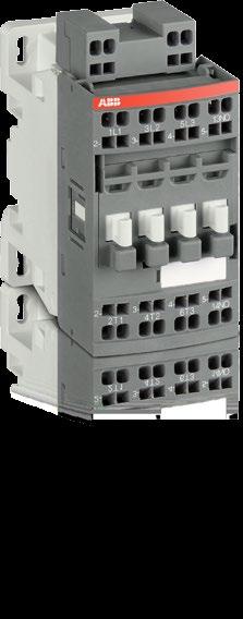
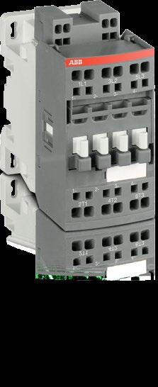
8 AF09ZB..S... AF26ZB..S 3-pole contactors 4 to 11 kw DC operated - spring terminals for connection with standard ferrules AF09ZB-30-10S 1SBC101099F00 Description AF09ZB..S... AF26ZB..S 3-pole contactors comply with the latest railway rolling stock standards to allow the use of AC voltages and allow installation in passengers or driver cabins for trains frequently operating tunnels or undergrounds. They are mainly used for controlling 3-phase motors and power circuits up to 690 V AC and 220 V DC. These contactors are of the block type design with 3 main poles. designed in accordance to the applicable parts of IEC and EN standard shocks and vibration withstand conforming to IEC 673 (category 1, class B) fire and smoke safety compliance to european standard EN (HL2 hazard level) electronic coil interface accepting a wide AC control voltage range (0.85 Uc min Uc max. according to IEC ) including several Uc control voltages ( Uc according to IEC 60077) used for battery supply low coil consumption built-in surge suppression side by side mounting without restriction from -40 C up to +70 C add-on auxiliary contact blocks for front or side mounting and a wide range of accessories. AF26ZB-30-00S 1SBC101100F00 Ordering details IEC UL / CSA Supply Rated operational 3-phase General control power current motor use voltage Uc θ 40 C rating rating (IEC 60077) 400 V 480 V 600 V AC (1) AC-3 AC-1 Rated control circuit voltage Uc min. Uc max. (IEC ) Auxiliary contacts fitted Type Order code Weight kw A hp A V DC V DC kg ,, AF09ZB-30-10S-21 1SBL6059R AF09ZB-30-01S-21 1SBL6059R , 96, AF09ZB-30-10S-22 1SBL6059R AF09ZB-30-01S-22 1SBL6059R AF09ZB-30-10S-23 1SBL6059R AF09ZB-30-01S-23 1SBL6059R / ,, AF12ZB-30-10S-21 1SBL156059R AF12ZB-30-01S-21 1SBL156059R , 96, AF12ZB-30-10S-22 1SBL156059R AF12ZB-30-01S-22 1SBL156059R AF12ZB-30-10S-23 1SBL156059R AF12ZB-30-01S-23 1SBL156059R ,, AF16ZB-30-10S-21 1SBL176059R AF16ZB-30-01S-21 1SBL176059R , 96, AF16ZB-30-10S-22 1SBL176059R AF16ZB-30-01S-22 1SBL176059R AF16ZB-30-10S-23 1SBL176059R AF16ZB-30-01S-23 1SBL176059R ,, AF26ZB-30-00S-21 1SBL236059R , 96, AF26ZB-30-00S-22 1SBL236059R AF26ZB-30-00S-23 1SBL236059R (1) Other control voltages, see voltage code table. Pkg (1 pce) Main dimensions mm, inches " " " " " " " " 35 mm EN/IEC " AF09ZB..S, AF12ZB..S, AF16ZB..S " " " AF26ZB..S 35 mm EN/IEC " " 1SBC100046S Rev. A 6 ABB

9 AF09(Z)B..S... AF26(Z)B..S 3-pole contactors 4 to 11 kw AC operated - spring terminals for connection with standard ferrules AF09ZB-30-10S 1SBC101099F00 Description AF09(Z)B..S... AF26(Z)B..S 3-pole contactors comply with the latest railway rolling stock standards and allow installation in passengers or driver cabins for trains frequently operating tunnels or undergrounds. They are mainly used for controlling 3-phase motors and power circuits up to 690 V AC and 220 V DC. These contactors are of the block type design with 3 main poles. designed in accordance to the applicable parts of IEC and EN standard shocks and vibration withstand conforming to IEC 673 (category 1, class B) fire and smoke safety compliance to european standard EN (HL2 hazard level) electronic coil interface accepting sinusoïdal AC 50/60 Hz control supplies included inside the wide control voltage range Uc min.... Uc max of the contactor. Max. permitted control voltage must not be exceeded during voltage fluctuation defined according to IEC or EN (see technical data) built-in surge suppression side by side mounting without restriction from -40 C up to +70 C add-on auxiliary contact blocks for front or side mounting and a wide range of accessories. AF26ZB-30-00S 1SBC101100F00 Ordering details IEC UL / CSA Rated control circuit Rated operational 3-phase General voltage power current motor use Uc min. Uc max. θ 40 C rating rating (IEC ) (1) 400 V 480 V 600 V AC AC-3 AC-1 Auxiliary contacts fitted Type Order code Weight kw A hp A V AC 50/60 Hz kg AF09ZB-30-10S-21 1SBL6059R AF09ZB-30-01S-21 1SBL6059R AF09ZB-30-10S-22 1SBL6059R AF09ZB-30-01S-22 1SBL6059R AF09ZB-30-10S-23 1SBL6059R AF09ZB-30-01S-23 1SBL6059R AF09B-30-10S- 1SBL7059R AF09B-30-01S- 1SBL7059R / AF12ZB-30-10S-21 1SBL156059R AF12ZB-30-01S-21 1SBL156059R AF12ZB-30-10S-22 1SBL156059R AF12ZB-30-01S-22 1SBL156059R AF12ZB-30-10S-23 1SBL156059R AF12ZB-30-01S-23 1SBL156059R AF12B-30-10S- 1SBL157059R AF12B-30-01S- 1SBL157059R AF16ZB-30-10S-21 1SBL176059R AF16ZB-30-01S-21 1SBL176059R AF16ZB-30-10S-22 1SBL176059R AF16ZB-30-01S-22 1SBL176059R AF16ZB-30-10S-23 1SBL176059R AF16ZB-30-01S-23 1SBL176059R AF16B-30-10S- 1SBL177059R AF16B-30-01S- 1SBL177059R AF26ZB-30-00S-21 1SBL236059R AF26ZB-30-00S-22 1SBL236059R AF26ZB-30-00S-23 1SBL236059R AF26B-30-00S- 1SBL237059R (1) Other control voltages, see voltage code table. Pkg (1 pce) Main dimensions mm, inches " " " " " " " " 35 mm EN/IEC " AF09(Z)B..S, AF12(Z)B..S, AF16(Z)B..S " " " AF26(Z)B..S 35 mm EN/IEC " " 1SBC100045S Rev. A ABB 7
10 AF09(Z)B..S... AF26(Z)B..S 3-pole contactors Main accessories Contactor and main accessories (other accessories available) AF(Z)B..S contactor AF(Z)B..S contactor (without top mounted coil terminal block) Fixing clips AF(Z)B..S contactor CAT4-11..S 2-pole auxiliary contact and / coil terminal block BX4-CA Protective cover VM4 CA4..S 4-pole auxiliary contact block BX4-CA Protective cover CAL4-11S 2-pole auxiliary contact block Top or bottom mounted coil terminal block BX4 Protective cover CA4..S 1-pole auxiliary contact block Main accessory fitting details Many configurations of accessories are possible depending on whether these are front-mounted or side-mounted. Contactor types Main poles Built-in auxiliary contacts Front-mounted accessories Side-mounted accessories Auxiliary contact blocks Mechanical Auxiliary contact blocks interlock unit (between 2 contactors) Left side Right side 1-pole CA4..S 2-pole CAT4-11..S 4-pole CA4..S VM4 2-pole CAL4-11S Max. N.C. built-in and add-on N.C. auxiliary contacts: 4 N.C. max. on positions 1, 2, 3, 4 and 3 N.C. max. on positions 1 ±30, 5 AF09(Z)B..S... AF16(Z)B..S max. or 1 or max max. or 1 or or 1 AF09(Z)B..S... AF16(Z)B..S AF26(Z)B..S max. or 1 or max. or max. or 1 or or 1 1SBC101979S ABB
11 AF09(Z)B..S... AF26(Z)B..S 3-pole contactors Spring terminals for connection with standard ferrules Main accessories Ordering details (1) 1SBC101110F00 For contactors Auxiliary contacts Type Order code Pkg qty Weight (1 pce) kg CA4-10S CAL4-11S 1SBC1011F00 Front-mounted instantaneous auxiliary contact blocks AF09(Z)B... AF26(Z)B..S 1 0 CA4-10S-T 1SBN010119T CA4-01S-T 1SBN010119T AF09(Z)B... AF16(Z)B-30-10S 2 2 CA4-22MS 1SBN0105R CA4-31MS 1SBN0105R AF26(Z)B-30-00S 2 2 CA4-22ES 1SBN0105R CA4-31ES 1SBN0105R CA4-40ES 1SBN0105R CA4-22MS 1SBC101125F00 Side-mounted instantaneous auxiliary contact blocks AF09(Z)B... AF26(Z)B..S 1 1 CAL4-11S 1SBN0100R Front-mounted instantaneous auxiliary contact and / coil terminal blocks AF09(Z)B... AF16(Z)B-30-10S 1 1 CAT4-11MS 1SBN010153R AF26(Z)B-30-00S 1 1 CAT4-11ES 1SBN010153R AF09(Z)B... AF16(Z)B-30-01S 1 1 CAT4-11US 1SBN010153R CAT4-11ES 1SBC101128F00 1SBC101117F00 Mechanical interlock unit AF09(Z)B... AF26(Z)B..S VM4 1SBN030105T Note: VM4 includes 2 fixing clips (BB4) to maintain together both contactors. Additional coil terminal block AF09(Z)B... AF26(Z)B..S LDC4S 1SBN070157T Protective covers All 1-stack contactors BX4 1SBN110108T For 4-pole CA4..S and 2-pole CAT4..S auxiliary contact blocks BX4-CA 1SBN110109W VM4 1SBC1015F00 Mounting piece AF09(Z)B... AF26(Z)B..S BP38-4 1SBN112303T (1) See "Main accessory fitting details" table. BX4 1SBC101994S0201 LDC4S 1SBC1016F00 1SBC1018F00 BX4-CA 1SBC1083F00 BP38-4 ABB 9
12 AF09(Z)B..S... AF26(Z)B..S 3-pole contactors Technical data Main pole - Utilization characteristics according to IEC Contactor types AF09(Z)B..S AF12(Z)B..S AF16(Z)B..S AF26(Z)B..S Standards IEC / and EN / IEC , IEC , EN (applicable parts) Fire and smoke EN45545 (HL2, HL3) Rated operational voltage Ue max. 690 V Rated frequency (without derating) 50 / 60 Hz Conventional free-air thermal current Ith acc. to IEC , open contactors, θ 40 C 24 A 24 A 24 A 35 A With conductor cross-sectional area 2.5 mm² 2.5 mm² 2.5 mm² 4 mm² AC-1 Utilization category For air temperature close to contactor Ie / Rated operational current AC-1 θ 40 C 22 A 24 A 24 A 35 A Ue max. 690 V, 50/60 Hz θ 60 C 18 A 20 A 20 A 30 A θ 70 C 15 A 16 A 16 A 25 A With conductor cross-sectional area 2.5 mm² 2.5 mm² 2.5 mm² 4 mm² AC-3 Utilization category For air temperature close to contactor θ 60 C Ie / Max. rated operational current AC-3 (1) M 3 3-phase motors Rated operational power AC-3 (1) M r.p.m. 50 Hz 1800 r.p.m. 60 Hz 3-phase motors V 9 A 12 A 18 A 26 A V 9 A 12 A 18 A 26 A 415 V 9 A 12 A 18 A 26 A 0 V 9 A 12 A 18 A 26 A 500 V 9.5 A 12.5 A 15 A 23 A 690 V 7 A 9 A 10.5 A 17 A V 2.2 kw 3 kw 4 kw 6.5 kw V 4 kw 5.5 kw 7.5 kw 11 kw 415 V 4 kw 5.5 kw 9 kw 11 kw 0 V 4 kw 5.5 kw 9 kw 15 kw 500 V 5.5 kw 7.5 kw 9 kw 15 kw 690 V 5.5 kw 7.5 kw 9 kw 15 kw Rated making capacity AC-3 10 x Ie AC-3 acc. to IEC Rated breaking capacity AC-3 8 x Ie AC-3 acc. to IEC Short-circuit protection device for contactors without thermal overload relay - Motor protection excluded (2) Ue 500 V AC - gg type fuse 25 A 25 A 25 A 40 A Rated short-time withstand current Icw 1 s 300 A 300 A 300 A 700 A at 40 C ambient temperature, in free air from a cold state 10 s 150 A 150 A 150 A 350 A 30 s 80 A 80 A 80 A 225 A 1 min 60 A 60 A 60 A 150 A 15 min 24 A 24 A 24 A 35 A Maximum breaking capacity cos φ = 0.45 at 0 V 250 A 250 A 250 A 500 A at 690 V 106 A 106 A 106 A 200 A Power dissipation per pole Ie / AC W 1.1 W 1.1 W 1.8 W Ie / AC W 0.3 W 0.6 W 1 W Max. electrical switching frequency AC cycles/h AC cycles/h AC-2, AC cycles/h 150 cycles/h (1) For the corresponding kw/a or hp/a values of 1500 r.p.m, 50 Hz or 1800 r.p.m, 60 Hz, 3-phase motors, see "Motor rated operational powers and currents". (2) For the protection of motor starters against short circuits, see "Coordination with short-circuit protection devices". 1SBC100047S Rev. A 10 ABB
13 AF09(Z)B..S... AF16(Z)B..S 3-pole contactors Technical data Main pole - Utilization characteristics according to UL / NEMA / CSA Contactor types AF09(Z)B..S AF12(Z)B..S AF16(Z)B..S Standards UL 508, CSA C22.2 N Maximum operational voltage 600 V NEMA size 00 0 NEMA continuous amp rating Thermal current 9 18 NEMA maximum horse power ratings 1-phase, 60 Hz 115 V AC 1/3 hp 1 hp 230 V AC 1 hp 2 hp NEMA maximum horse power ratings 3-phase, 60 Hz 200 V AC 1-1/2 hp 3 hp 230 V AC 1-1/2 hp 3 hp 460 V AC 2 hp 5 hp 575 V AC 2 hp 5 hp UL / CSA general use rating 600 V AC 20 A 20 A 20 A With conductor cross-sectional area AWG 12 AWG 12 AWG 12 UL / CSA maximum 1-phase motor rating Full load current 120 V AC.8 A 16 A 16 A 240 V AC 10 A 12 A 12 A Horse power rating 120 V AC 3/4 hp 1 hp 1 hp 240 V AC 1-1/2 hp 2 hp 2 hp UL / CSA maximum 3-phase motor rating Full load current V AC 7.8 A 11 A 11 A V AC 6.8 A 9.6 A 15.2 A V AC 7.6 A 11 A A V AC 9 A 11 A 11 A Horse power rating V AC 2 hp 3 hp 3 hp V AC 2 hp 3 hp 5 hp V AC 5 hp 7-1/2 hp 10 hp V AC 7-1/2 hp 10 hp 10 hp Short-circuit protection device for contactors without thermal overload relay - Motor protection excluded Fuse rating 30 A 30 A 60 A Fuse type, 600 V J Maximum electrical switching frequency For general use 600 cycles/h For motor use 1200 cycles/h 1SBC100048S0201 ABB 11
14 AF09(Z)B..S... AF26(Z)B..S 3-pole contactors Technical data General technical data Contactor types AF09(Z)B..S AF12(Z)B..S AF16(Z)B..S AF26(Z)B..S Rated insulation voltage Ui acc. to IEC V acc. to UL / CSA 600 V - Rated impulse withstand voltage Uimp. 6 kv Electromagnetic compatibility Devices complying with IEC / EN Environments A EN Ambient air temperature close to contactor Operation Fitted with thermal overload relay C Without thermal overload relay C Storage C Climatic withstand Category B according to IEC Annex Q Maximum operating altitude (without derating) 3000 m Mechanical durability Number of operating cycles 10 millions operating cycles Maximum switching frequency 3600 cycles/h Shock and vibration withstand acc. to IEC 673 Category 1, class B Magnet system characteristics Contactor types AF09(Z)B..S AF12(Z)B..S AF16(Z)B..S AF26(Z)B..S Coil operating limits acc. to IEC DC supply (AF..ZB) at θ 70 C 0.85 x Uc min x Uc max (AF..B) at θ 60 C 0.85 x Uc min x Uc max; at θ 70 C 0.85 x Uc min... Uc max AC supply at θ 60 C 0.85 x Uc min x Uc max at θ 70 C 0.85 x Uc min... Uc max DC control voltage Rated control circuit voltage Uc (AF..ZB) V DC - (AF..B) V DC Coil consumption Average pull-in value (AF..ZB) W - (AF..B) 50 W Average holding value (AF..ZB) 1.7 W - (AF..B) 2 W PLC-output control (AFZB) 500 ma 24 V DC AC control voltage 50/60 Hz Rated control circuit voltage Uc (AF..ZB) V AC - (AF..B) V AC Coil consumption Average pull-in value (AF..ZB) 16 VA - (AF..B) 50 VA Average holding value (AF..ZB) 1.7 VA / 1.5 W - (AF..B) 2.2 VA / 2 W Max. permitted control voltage during voltage fluctuation defined acc. to IEC / EN Rated control circuit voltage / Max. permitted control voltage V AC 50/60 Hz / 75 V AC 50/60 Hz V AC 50/60 Hz / 150 V AC 50/60 Hz V AC 50/60 Hz / 275 V AC 50/60 Hz V AC 50/60 Hz / 550 V AC 50/60 Hz Drop-out voltage 60 % of Uc min. Operating time Between coil energization and: N.O. contact closing ms N.C. contact opening ms Between coil de-energization and: N.O. contact opening ms N.C. contact closing ms Mounting characteristics and conditions for use Contactor types AF09(Z)B..S AF12(Z)B..S AF16(Z)B..S AF26(Z)B..S Mounting positions Pos Pos. 4 Pos. 3 Mounting distances Fixing On rail according to IEC 60715, EN By screws (not supplied) Pos. 1 Pos Pos. 5 Max. N.C. built-in and add-on N.C. auxiliary contacts: see accessory fitting details for a 3-pole contactor AF09(Z)B..S... AF26(Z)B..S. The contactors can be assembled side by side 35 x 7.5 mm or 35 x 15 mm 2 x M4 screws placed diagonally 1SBC100049S ABB
15 AF09(Z)B..S... AF26(Z)B..S 3-pole contactors Technical data Connecting characteristics Contactor types AF09(Z)B..S AF12(Z)B..S AF16(Z)B..S AF26(Z)B..S Main terminals Spring terminals Connection capacity (min.... max.) Main conductors (poles) Rigid Solid ( 4 mm²) 1 x mm² mm² 2 x mm² mm² Flexible with non insulated ferrule 1 x mm² mm² 2 x mm² mm² Flexible with insulated ferrule 1 x mm² mm² 2 x mm² mm² Connection capacity acc. to UL/CSA 1 or 2 x AWG Stripping length 10 mm mm Auxiliary conductors (built-in auxiliary terminals + coil terminals) Rigid solid 1 x mm² 2 x mm² Flexible with non insulated ferrule 1 x mm² 2 x mm² Flexible with insulated ferrule 1 x mm² 2 x mm² Connection capacity acc. to UL/CSA 1 or 2 x AWG Stripping length 10 mm Degree of protection acc. to IEC / EN and IEC / EN Main terminals IP20 Coil terminals IP20 Built-in auxiliary terminals IP20 Screw terminals Flat Ø 3.5 1SBC100050S0201 ABB
16 AF09(Z)B..S... AF16(Z)B..S 3-pole contactors Technical data Built-in auxiliary contacts according to IEC Contactor types AF09(Z)B..S AF12(Z)B..S AF16(Z)B..S Rated operational voltage Ue max. 690 V Rated frequency (without derating) 50 / 60 Hz Conventional free air thermal current Ith - θ 40 C 16 A Ie / Rated operational current AC-15 acc. to IEC V 50/60 Hz 6 A V 50/60 Hz 4 A V 50/60 Hz 3 A 500 V 50/60 Hz 2 A 690 V 50/60 Hz 2 A Making capacity AC x Ie AC-15 acc. to IEC Breaking capacity AC x Ie AC-15 acc. to IEC Ie / Rated operational current DC- acc. to IEC V DC 6 A / 4 W 48 V DC 2.8 A / 4 W 72 V DC 1 A / 72 W 110 V DC 0.55 A / 60 W 125 V DC 0.55 A / 69 W 220 V DC 0.27 A / 60 W 250 V DC 0.27 A / 68 W 400 V DC 0.15 A / 60 W 500 V DC 0. A / 65 W 600 V DC 0.1 A / 60 W Short-circuit protection device gg type fuse 10 A Rated short-time withstand current Icw for 1.0 s 100 A for 0.1 s 0 A Minimum switching capacity 12 V / 3 ma with failure rate acc. to IEC Non-overlapping time between N.O. and N.C. contacts 2 ms Power dissipation per pole at 6 A 0.1 W Maximum electrical switching frequency AC cycles/h DC- 900 cycles/h Mechanically linked contacts acc. to annex L of IEC Built-in N.O. or N.C. auxiliary contacts and additional N.O. or N.C. auxiliary contacts (CA4..S, CAL4..S, CAT4..S aux. contact blocks) are mechanically linked contacts. Mirror contacts acc. to annex F of IEC Built-in N.C. auxiliary contacts or additional N.C. auxiliary contacts (CA4..S, CAL4..S, CAT4..S aux. contact blocks) are mirror contacts. Built-in auxiliary contacts according to UL / CSA Contactor types AF09(Z)B..S AF12(Z)B..S AF16(Z)B..S Maximum operational voltage 600 V AC, 600 V DC Pilot duty A600, Q600 AC thermal rated current 10 A AC maximum volt-ampere making 7200 VA AC maximum volt-ampere breaking 720 VA DC thermal rated current 2.5 A DC maximum volt-ampere making-breaking 69 VA 1SBC100051S0201 ABB
17 AF09(Z)B..S... AF26(Z)B..S 3-pole contactors DC circuit switching General The arc switching on DC is more difficult than on AC. For selecting a contactor it is essential to determine the current, the voltage and the L/R time constant of the controlled load For information, typical time constant values are quoted hereafter: non inductive loads such as resistance furnaces (L/R 1 ms), inductive loads such as shunt motors (L/R 2 ms) or series motors (L/R 7.5 ms) The addition of a resistor in parallel with an inductive winding helps in the elimination of the arcs All the poles required for breaking must be connected in series between the load and the source polarity not linked to earth (or chassis). Technical data The tables indicate for the standard contactors the Ie max. operating currents depending on: the utilization category (i.e. L/R) DC-1, DC-3, DC-5 as defined in the IEC publication, the operating voltage Ue and the pole coupling details. Ampere values quoted in these tables are valid for a C temperature close to the contactors, as long as these values do not exceed the AC-1. Ampere values for the corresponding ambient temperature Max. switching frequency: 300 cycles/h. Selection table Contactor types AF09(Z)B..S AF12(Z)B..S AF16(Z)B..S AF26(Z)B..S 3-pole Utilization category DC-1, L/R 1 ms 72 V 22 A 24 A 24 A 35 A 110 V 10 A 15 A 20 A V V V V 22 A 24 A 24 A 35 A 110 V 22 A 24 A 24 A 35 A 220 V 10 A 15 A 20 A - 72 V 22 A 24 A 24 A 35 A 110 V 22 A 24 A 24 A 35 A 220 V 22 A 24 A 24 A 35 A Utilization category DC-3, L/R 2 ms 72 V 22 A 24 A 24 A 35 A 110 V 6 A 7 A 8 A V V V 22 A 24 A 24 A 35 A 110 V 22 A 24 A 24 A 35 A 220 V 6 A 7 A 8 A - 72 V 22 A 24 A 24 A 35 A 110 V 22 A 24 A 24 A 35 A 220 V 22 A 24 A 24 A 35 A Utilization category DC-5, L/R 7.5 ms 72 V 9 A 12 A 16 A 20 A 110 V 4 A 4 A 4 A V V V 22 A 24 A 24 A 35 A 110 V 10 A 15 A 20 A 35 A 220 V 4 A 4 A 4 A - 72 V 22 A 24 A 24 A 35 A 110 V 22 A 24 A 24 A 35 A 220 V 9 A 12 A 16 A 20 A 1SBC101992S0201 ABB 15
18 AF09(Z)B..S... AF26(Z)B..S 3-pole contactors Electrical durability and utilization categories General Utilization categories determine the current making and breaking conditions relating to the characteristics of the loads to be controlled by the contactors. International standard IEC and European standard EN are the standards to be referred to. If Ic is the current to be broken by the contactor and Ie the rated operational current normally drawn by the load, then: Categories AC-1 and AC-3: Ic = Ie Category AC-2: Ic = 2.5 x Ie Category AC-4: Ic = 6 x Ie Generally speaking Ic = m x Ie where m is a multiple of the load operational current. On next pages, the curves corresponding to categories AC-1, AC-3 and AC-4 represent the electrical durability variation of standard contactors in relation to the breaking current Ic. Electrical durability is expressed in millions of operating cycles. Curve utilization mode Electrical durability forecast and contactor selection for categories AC-1, AC-2, AC-3 or AC-4 Note the characteristics of the load to be controlled: Operational voltage... Ue Current normally drawn... Ie (Ue / Ie / kw relation for motors, see "Motor rated operational powers and currents"). Utilization category... AC-1, AC-2, AC-3 or AC-4 Breaking current... Ic = Ie for AC-1 and for AC-3 ; Ic = 2.5 x Ie for AC-2 ; Ic = 6 x Ie for AC-4 Define the number of operating cycles N required. On the diagram corresponding to the operational category, select the contactor with the curve immediately above the intersection point (Ic ; N). Electrical durability forecast and contactor selection for mixed duty motor control: AC-3 (Ic = Ie) type switching off while "motor running" and, occasionally, AC-4 (Ic = 6 x Ie) type switching off while "motor accelerating" Note the characteristics of the motor to be controlled: Operational voltage... Ue Current normally drawn while "motor running"... Ie (Ue / Ie / kw relation for motors, see "Motor rated operational powers and currents") Breaking current for AC-3... Ic = Ie Breaking current for AC-4 while "motor accelerating"... Ic = 6 x Ie Percentage of AC-4 operating cycles... K (on the basis of the total number of operating cycles) Define the total number of operating cycles N required. Note the smallest contactor rating compatible for AC-3 (Ue / Ie) on Main pole utilization characteristic table (see Technical data ). For the selected contactor make a note of the following in relation to the voltage using diagram AC-3 in next pages: The number of operating cycles A for Ic = Ie (AC-3) The number of operating cycles B for Ic = 6 x Ie (AC-4) Calculate the estimated number of cycles N (N is always below A) N'= A K (A/B - 1) If N' is too low in relation to the target N, calculate the estimated number of cycles for a higher contactor rating. Case of uninterrupted duty For uninterrupted duty, some verifications of preventing maintenance are necessary to check the functionality of the concerned product (consult us). The combinated effect of environmental conditions and the proper temperature of the product may require some disposals. As a matter of fact, for this duty, the use duration prevails over the number of operating cycles. 1SBC100156S ABB
19 AF09(Z)B..S... AF26(Z)B..S 3-pole contactors Electrical durability Electrical durability for AC-1 utilization category - Ue 690 V. Ambient temperature 60 C Switching non-inductive or slightly inductive loads. The breaking current Ic for AC-1 is equal to the rated operational current of the load. Maximum electrical switching frequency: see "Technical data". Millions of operating cycles 10 AF09(Z)B..S AF12(Z)B..S AF16(Z)B..S AF26(Z)B..S Breaking current Ic (A) AF09(Z)B..S AF26(Z)B..S 3-pole contactors AC-1 electrical durability 1SBC100041S0201 ABB 17
20 AF09(Z)B..S... AF26(Z)B..S 3-pole contactors Electrical durability Electrical durability for AC-3 utilization category Switching cage motors: starting and switching off running motors. The breaking current Ic for AC-3 is equal to the rated operational current Ie (Ie = motor full load current). Maximum electrical switching frequency: see "Technical data". AC-3 - Ue 0 V - Ambient temperature 60 C Millions of operating cycles 10 AF09(Z)B..S AF12(Z)B..S AF16(Z)B..S AF26(Z)B..S Breaking current Ic (A) AF09(Z)B..S AF26(Z)B..S 3-pole contactors AC-3 electrical durability for Ue 0 V 1SBC100042S ABB
21 AF09(Z)B..S... AF26(Z)B..S 3-pole contactors Electrical durability Electrical durability for AC-4 utilization category Switching cage motors: starting, reverse operation and step-by-step operation. The breaking current Ic is equal to 6 x Ie for AC-4, keeping in mind that Ie is the motor rated operational current (Ie = motor full-load current). Maximum electrical switching frequency: see "Technical data". AC-4 - Ue 0 V - Ambient temperature 60 C Millions of operating cycles AF09(Z)B..S AF12(Z)B..S AF16(Z)B..S AF26(Z)B..S Breaking current Ic (A) 1SBC1000S0201 ABB 19
22 AF09(Z)B..S... AF26(Z)B..S 3-pole contactors - with spring terminals Terminal marking and positioning AF09(Z)B..S... AF26(Z)B..S contactors - AC / DC operated Standard devices without addition of auxiliary contacts 1L1 3L2 5L3 1L1 3L2 5L3 21 1L1 3L2 5L3 1L1 3L2 5L3 1L1 3L2 5L3 21 1L1 3L2 5L3 2T1 4T2 6T3 2T1 4T2 6T3 22 2T1 4T2 6T3 2T1 4T2 6T3 2T1 4T2 6T3 22 2T1 4T2 6T3 AF09(Z)B... AF16(Z)B S AF09(Z)B... AF16(Z)B S AF26(Z)B S AF09(Z)B... AF16(Z)B S AF09(Z)B... AF16(Z)B S AF26(Z)B S 1L1 3L2 5L3 1L1 3L2 5L3 1L1 3L2 5L L1 3L2 5L L1 3L2 5L3 21 2T1 4T2 6T3 2T1 4T2 6T3 2T1 4T2 6T3 2T1 4T2 6T T1 4T2 6T3 22 AF09(Z)B... AF16(Z)B S AF26(Z)B S AF26(Z)B S AF09(Z)B... AF26(Z)B S AF26(Z)B S Other possible contact combinations with auxiliary contacts added by the user 1L1 3L2 5L3 21 1L1 3L2 5L3 1L1 3L2 5L3 1L1 3L2 5L3 1L1 3L2 5L = = T1 4T2 6T3 Combination T1 4T2 6T3 2T1 4T2 6T3 2T1 4T2 6T3 2T1 4T2 6T3 Combination 11 = AF09(Z)B... AF16(Z)B S + CA4-01S Combination 11 = AF26(Z)B S + CA4-10S + CA4-01S 1L1 3L2 5L3 21 1L1 3L2 5L3 1L1 3L2 5L3 1L1 3L2 5L3 1L1 3L2 5L3 21 = = T1 4T2 6T3 Combination L1 3L2 5L T1 4T2 6T3 2T1 4T2 6T3 Combination 21 = AF09(Z)B... AF16(Z)B S + CAT4-11MS 2T1 4T2 6T3 2T1 4T2 6T3 Combination 32 = AF09(Z)B... AF16(Z)B S + CA4-22MS 2T1 4T2 6T3 Combination L1 3L2 5L3 X 21X X 21X 1L1 3L2 5L3 22X X = + 22X X 1L1 3L2 5L3 X 21X 2T1 4T2 6T3 Combination 21 = 2T1 4T2 6T3 CAL4-11S + AF09(Z)B... AF16(Z)B S 2T1 4T2 6T3 Combination 21 X 22X Note: Only AF..(Z)B contactor with DC control voltage V DC need to respect the connection polarities indicated close to the coil terminals: + for the positive pole and - for the negative pole. 1SBC101997S ABB
23 AF09(Z)B..S... AF16(Z)B..S 3-pole contactors - with spring terminals Main dimensions mm, inches " " " " ø " 2 x M U " " 35 mm EN/IEC " " " " AF09(Z)B..S, AF12(Z)B..S, AF16(Z)B..S " " AF09(Z)B..S, AF12(Z)B..S, AF16(Z)B..S " " " " " " " " " " 35 mm EN/IEC " " " 35 mm EN/IEC " AF09(Z)B..S, AF12(Z)B..S, AF16(Z)B..S + CA4..S 1-pole auxiliary contact block AF09(Z)B..S, AF12(Z)B..S, AF16(Z)B..S + CAL4-11S 2-pole auxiliary contact block " " " " " " " " " " " 35 mm EN/IEC " " 35 mm EN/IEC " AF09(Z)B..S, AF12(Z)B..S, AF16(Z)B..S + CA4..S 4-pole auxiliary contact block AF09(Z)B..S, AF12(Z)B..S, AF16(Z)B..S + CAT4..S 2-pole auxiliary contact and coil terminal block Note: contactor lateral distance to grounded component 2 mm 0.08" min. 1SBC101998S0201 ABB 21
24 AF26(Z)B..S 3-pole contactors - with spring terminals Main dimensions mm, inches " " " " ø " 2 x M U " " 35 mm EN/IEC " " " " AF26(Z)B..S " AF26(Z)B..S " " " " " " " " " " " 35 mm EN/IEC " " " 35 mm EN/IEC " AF26(Z)B..S + CA4..S 1-pole auxiliary contact block AF26(Z)B..S + CAL4-11S 2-pole auxiliary contact block " " " " " " " " " " " 35 mm EN/IEC " " 35 mm EN/IEC " AF26(Z)B..S + CA4..S 4-pole auxiliary contact block AF26(Z)B..S + CAT4..S 2-pole auxiliary contact and coil terminal block Note: contactor lateral distance to grounded component 2 mm 0.08" min. 1SBC101999S ABB
25 NF(Z)B 4 and 8 pole contactor relays Ordering details 4 and 8-pole contactor relays NFZB..S DC operated 24 NF(Z)B..S AC operated 25 Main accessories 26 Technical data Main pole - Utilization characteristics according to IEC 28 Main pole - Utilization characteristics according to UL / CSA 28 General technical data 29 Magnet system and mounting characteristics 29 Connecting characteristics 30 Terminal positioning and marking 31 Main dimensions 32 Voltage code table 40 ABB 23
26 NFZB..S 4 and 8-pole contactor relays DC operated - spring terminals for connection with standard ferrules NFZB22ES 1SBC101106F00 Description NFZB..S contactor relays comply with the latest railway rolling stock standards and allow installation in passengers or driver cabins for trains frequently operating tunnels or undergrounds. They are used for switching auxiliary and control circuits. These contactor relays are of the block type design with 4 or 8 main poles. designed in accordance to the applicable parts of IEC and EN standard shocks and vibration withstand conforming to IEC 673 (category 1, class B) fire and smoke safety compliance to european standard EN (HL2 hazard level) electronic coil interface accepting a wide DC control voltage range (0.85 Uc min Uc max. according to IEC ) including several Uc control voltages ( Uc according to IEC 60077) used for battery supply low coil consumption built-in surge suppression side by side mounting without restriction from -40 C up to +70 C add-on auxiliary contact blocks for front or side mounting and a wide range of accessories. NFZBES 1SBC101107F00 Ordering details Number of contacts (1) Other control voltages, see voltage code table Supply control voltage Uc (1) Rated control circuit voltage Uc min.... Uc max. Type Order code Weight Pkg (1 pce) (IEC 60077) (IEC ) V DC V DC kg 24,, NFZB22ES-21 1SBH6059R , 96, NFZB22ES-22 1SBH6059R NFZB22ES-23 1SBH6059R ,, NFZB31ES-21 1SBH6059R , 96, NFZB31ES-22 1SBH6059R NFZB31ES-23 1SBH6059R ,, NFZB40ES-21 1SBH6059R , 96, NFZB40ES-22 1SBH6059R NFZB40ES-23 1SBH6059R ,, NFZBES-21 1SBH6059R , 96, NFZBES-22 1SBH6059R NFZBES-23 1SBH6059R ,, NFZB62ES-21 1SBH6059R , 96, NFZB62ES-22 1SBH6059R NFZB62ES-23 1SBH6059R ,, NFZB80ES-21 1SBH6059R , 96, NFZB80ES-22 1SBH6059R NFZB80ES-23 1SBH6059R Main dimensions mm, inches " " " " " " " " " 35 mm EN/IEC " NFZB22ES, NFZB31ES, NFZB40ES " " " 35 mm EN/IEC " NFZBES, NFZB62ES, NFZB80ES 1SBC100053S Rev. A 24 ABB
27 NF(Z)B..S 4 and 8-pole contactor relays AC operated - spring terminals for connection with standard ferrules NFZB22ES 1SBC101106F00 Description NF(Z)B..S contactor relays comply with the latest railway rolling stock standards and allow installation in passengers or driver cabins for trains frequently operating tunnels or undergrounds. They are used for switching auxiliary and control circuits. These contactor relays are of the block type design with 4 or 8 main poles. designed in accordance to the applicable parts of IEC and EN standard shocks and vibration withstand conforming to IEC 673 (category 1, class B) fire and smoke safety compliance to european standard EN (HL2 hazard level) electronic coil interface accepting sinusoïdal AC 50/60 Hz control supplies included inside the wide control voltage range Uc min.... Uc max of the contactor. Max. permitted control voltage must not be exceeded during voltage fluctuation defined according to IEC or EN (see technical data). built-in surge suppression side by side mounting without restriction from -40 C up to +70 C add-on auxiliary contact blocks for front or side mounting and a wide range of accessories. NFZBES 1SBC101107F00 Ordering details Number of contacts Rated control circuit voltage Uc min.... Uc max. (IEC ) Type Order code Weight Pkg (1 pce) V AC 50/60 Hz kg NFZB22ES-21 1SBH6059R NFZB22ES-22 1SBH6059R NFZB22ES-23 1SBH6059R NFB22ES- 1SBH7059R NFZB31ES-21 1SBH6059R NFZB31ES-22 1SBH6059R NFZB31ES-23 1SBH6059R NFB31ES- 1SBH7059R NFZB40ES-21 1SBH6059R NFZB40ES-22 1SBH6059R NFZB40ES-23 1SBH6059R NFB40ES- 1SBH7059R NFZBES-21 1SBH6059R NFZBES-22 1SBH6059R NFZBES-23 1SBH6059R NFBES- 1SBH7059R NFZB62ES-21 1SBH6059R NFZB62ES-22 1SBH6059R NFZB62ES-23 1SBH6059R NFB62ES- 1SBH7059R NFZB80ES-21 1SBH6059R NFZB80ES-22 1SBH6059R NFZB80ES-23 1SBH6059R NFB80ES- 1SBH7059R Main dimensions mm, inches " " " " " " " " " 35 mm EN/IEC " NF(Z)B22ES, NF(Z)B31ES, NF(Z)B40ES " " " 35 mm EN/IEC " NF(Z)BES, NF(Z)B62ES, NF(Z)B80ES 1SBC100052S Rev. A ABB 25
28 NF(Z)B..S 4 and 8-pole contactor relays Main accessories Contactor relays and main accessories (other accessories available) NF(Z)B..S contactor relay Top or bottom mounted coil terminal block CAL4-11S 2-pole auxiliary contact block CA4..S 4-pole auxiliary contact block BX4-CA Protective cover BX4 Protective cover CA4..S 1-pole auxiliary contact block Main accessory fitting details Many configurations of accessories are possible depending on whether these are front-mounted or side-mounted. Contactor relay types Main poles Front-mounted accessories Auxiliary contact blocks Side-mounted accessories Auxiliary contact blocks Left side Right side 1-pole CA4..S 4-pole CA4..S 2-pole CAL4-11S Max. add-on N.C. auxiliary contacts: 3 N.C. max. on positions 1, 2, 3, 4 and 2 N.C. max. on positions 5 NF(Z)B ES 4 max. or ES 2 max Max. add-on N.C. auxiliary contacts: 4 N.C. max. on positions 1, 2, 3, 4 and 3 N.C. max. on positions 5 NF(Z)B ES 4 max. or max NF(Z)B ES ES 8 0 ES 1SBC101993S ABB
29 NF(Z)B..S 4 and 8-pole contactor relays Spring terminals for connection with standard ferrules Main accessories Ordering details (1) 1SBC101110F00 For contactors Auxiliary contacts Type Order code Pkg qty Weight (1 pce) kg CA4-10S 1SBC1011F00 Front-mounted instantaneous auxiliary contact blocks NF(Z)B..S 1 0 CA4-10S-T 1SBN010119T CA4-01S-T 1SBN010119T NF(Z)B..S 2 2 CA4-22NS 1SBN0105R CA4-31NS 1SBN0105R CA4-40NS 1SBN0105R CAL4-11S Side-mounted instantaneous auxiliary contact blocks NF(Z)B..S 1 1 CAL4-11S 1SBN0100R SBC101125F00 Additional coil terminal block NF(Z)B..S LDC4S 1SBN070157T CA4-22NS 1SBC1015F00 Protective covers All 1-stack contactor relays BX4 1SBN110108T For 4-pole CA4..S auxiliary contact blocks BX4-CA 1SBN110109W (1) See "Main accessory fitting details" table. BX4 1SBC101995S0201 LDC4S 1SBC1016F00 1SBC1018F00 BX4-CA ABB 27
30 NF(Z)B..S 4 and 8-pole contactor relays Technical data Contact utilization characteristics according to IEC Contactor relay types NF(Z)B..S Standards IEC / and EN / IEC , IEC , EN (applicable parts) Fire and smoke EN45545 (Hazard level HL2) Rated operational voltage Ue max. 690 V Conventional free-air thermal current Ith θ 40 C 16 A Rated frequency (without derating) 50 / 60 Hz Ie / Rated operational current AC-15 acc. to IEC V 50/60 Hz 6 A V 50/60 Hz 4 A V 50/60 Hz 3 A 500 V 50/60 Hz 2 A 690 V 50/60 Hz 2 A Making capacity AC x Ie AC-15 acc. to IEC Breaking capacity AC x Ie AC-15 acc. to IEC Ie / Rated operational current DC- acc. to IEC V DC 6 A / 4 W 48 V DC 2.8 A / 4 W 72 V DC 1 A / 72 W 110 V DC 0.55 A / 60 W 125 V DC 0.55 A / 69 W 220 V DC 0.27 A / 60 W 250 V DC 0.27 A / 68 W 400 V DC 0.15 A / 60 W 500 V DC 0. A / 65 W 600 V DC 0.1 A / 60 W Short-circuit protection device gg type fuse 10 A Rated short-time withstand current Icw for 1.0 s 100 A for 0.1 s 0 A Minimum switching capacity with failure rate acc. to IEC V / 3 ma 10-7 Non-overlapping time between N.O. and N.C. contacts 2 ms Power dissipation per pole at 6 A 0.1 W Max. electrical switching frequency AC cycles/h DC- 900 cycles/h Mechanically linked contacts (according to annex L of IEC ) Built-in N.O. or N.C. auxiliary contacts and additional N.O. or N.C. auxiliary contacts (CA4..S, CAL4..S aux. contact blocks) are mechanically linked contacts Contact utilization characteristics according to UL / CSA Contactor relay types NF(Z)B..S Standards UL 508, CSA C22.2 N Max. operational voltage 600 V AC, 600 V DC Pilot duty A600, Q600 AC thermal rated current 10 A AC maximum volt-ampere making 7200 VA AC maximum volt-ampere breaking 720 VA DC thermal rated current 2.5 A DC maximum volt-ampere making-breaking 69 VA 1SBC100054S ABB
31 NF(Z)B..S 4 and 8-pole contactor relays Technical data General technical data Contactor types Rated insulation voltage Ui acc. to IEC acc. to UL / CSA Rated impulse withstand voltage Uimp. Electromagnetic compatibility NF(Z)B..S 690 V 600 V 6 kv Devices complying with IEC / EN Environments A EN Ambient air temperature close to contactor Operation in free air C Storage C Climatic withstand Category B according to IEC Annex Q Maximum operating altitude (without derating) 3000 m Mechanical durability Number of operating cycles 20 millions operating cycles Maximum switching frequency 6000 cycles/h Shock and vibration withstand acc. to IEC 673 Category 1, class B Magnet system characteristics Contactor types NF(Z)B..S Coil operating limits acc. to IEC DC supply (NFZB) at θ 70 C 0.85 x Uc min x Uc max (NFB) at θ 60 C 0.85 x Uc min x Uc max; at θ 70 C 0.85 x Uc min... Uc max AC supply at θ 60 C 0.85 x Uc min x Uc max at θ 70 C 0.85 x Uc min... Uc max DC control voltage Rated control circuit voltage Uc (NFZB) V DC - (NFB) V DC Coil consumption Average pull-in value (NFZB) W - (NFB) 50 W Average holding value (NFZB) 1.7 W - (NFB) 2 W PLC-output control (NFZB) 500 ma 24 V DC AC control voltage 50/60 Hz Rated control circuit voltage Uc (NFZB) V AC - (NFB) V AC Coil consumption Average pull-in value (NFZB) 16 VA - (NFB) 50 VA Average holding value (NFZB) 1.7 VA / 1.5 W - (NFB) 2.2 VA / 2 W Max. permitted control voltage during voltage fluctuation defined acc. to IEC / EN Rated control circuit voltage / Max. permitted control voltage V AC 50/60 Hz / 75 V AC 50/60 Hz V AC 50/60 Hz / 150 V AC 50/60 Hz V AC 50/60 Hz / 275 V AC 50/60 Hz V AC 50/60 Hz / 550 V AC 50/60 Hz Drop-out voltage 60 % of Uc min. Operating time Between coil energization and: N.O. contact closing ms N.C. contact opening ms Between coil de-energization and: N.O. contact opening ms N.C. contact closing ms Mounting characteristics and conditions for use Contactor types NF(Z)B..S Mounting positions Pos Pos. 4 Pos. 3 Mounting distances Fixing On rail according to IEC 60715, EN By screws (not supplied) Pos. 1 Pos Pos. 5 Max. N.C. built-in and add-on N.C. auxiliary contacts: see accessory fitting details for a 3-pole contactor NF(Z)B..S. The contactor relays can be assembled side by side 35 x 7.5 mm or 35 x 15 mm 2 x M4 screws placed diagonally 1SBC100055S0201 ABB 29
32 NF(Z)B..S 4 and 8-pole contactor relays Technical data Connecting characteristics Contactor types Main terminals NF(Z)B..S Spring terminals Connection capacity (min.... max.) Pole and coil terminals Rigid solid 1 x mm² 2 x mm² Flexible with non insulated ferrule 1 x mm² 2 x mm² Flexible with insulated ferrule 1 x mm² 2 x mm² Connection capacity acc. to UL/CSA 1 or 2 x AWG Stripping length 10 mm Degree of protection acc. to IEC / EN and IEC / EN All terminals IP20 Screw terminals Flat Ø 3.5 1SBC100056S ABB
33 NF(Z)B..S contactor relays Terminal marking and positioning Standard devices without addition of auxiliary contacts NF(Z)B..22ES NF(Z)B..31ES NF(Z)B..22ES NF(Z)B..31ES NF(Z)B..40ES NF(Z)B..40ES NF(Z)B..ES NF(Z)B..62ES NF(Z)B..ES NF(Z)B..62ES NF(Z)B..80ES NF(Z)B..80ES Other possible contact combinations with auxiliary contacts added by the user = + = + + Combination 41E Combination 41 = NF(Z)B..31ES + CA4-10S Combination 42 = NF(Z)B..40ES + CA4-01S + CA4-01S Combination 42E X 23 X X 21X 21X 21X X 22X = + = + Combination 51E 22X 22X X 24 X Combination 51 = CAL4-11S + NF(Z)B..40ES Combination 62 = NF(Z)B..40ES + CA4-22NS Combination 62E Note: Only NFZ contactor relays with DC control voltage V DC need to respect the connection polarities indicated close to the coil terminals: + for the positive pole and - for the negative pole. 1SBC100001S0201 ABB 31
34 NF(Z)B..S contactor relays Main dimensions mm, inches " " " " ø " 2 x M U " " 35 mm EN/IEC " " " " NF(Z)B..22ES, NF(Z)B..31ES, NF(Z)B..40ES " " NF(Z)B..22ES, NF(Z)B..31ES, NF(Z)B..40ES " " " " " " " " " " 35 mm EN/IEC " " " 35 mm EN/IEC " NF(Z)B..22ES, NF(Z)B..31ES, NF(Z)B..40ES + CA4..S 1-pole auxiliary contact block NF(Z)B..22ES, NF(Z)B..31ES, NF(Z)B..40ES + CAL4-11S 2-pole auxiliary contact block " " " " " " " " " " " 35 mm EN/IEC " " " 35 mm EN/IEC " NF(Z)B..22ES, NF(Z)B..31ES, NF(Z)B..40ES + CA4..S 4-pole auxiliary contact block NF(Z)B..ES, NF(Z)B..62ES, NF(Z)B..80ES Note: Contactor relay lateral distance to grounded component 2 mm 0.08" min. 1SBC100037S ABB
35 Accessories for AF09(Z)B..S... AF26(Z)B..S Auxiliary contact blocks Electrical durability 36 Terminal positioning and marking 37 Other accessories 38 Voltage code table 40 ABB
36 Auxiliary contact blocks Spring terminals for connection with standard ferrules Description CA4-10S 1SBC101110F00 CAL4-11S 1SBC1011F00 The auxiliary contact blocks are used for the operation of auxiliary and control circuits for standard industrial environments. Types of auxiliary contact blocks for front mounting: CA4..S 1 or 4-pole block, with instantaneous N.O., N.C. contacts CAT4..S 2-pole block, front-mounted, instantaneous N.O. + N.C. contacts with / coil terminal connection on front face CAL4..S 2-pole block, with instantaneous N.O. + N.C. contacts clipped onto the right and/or left side of the contactors. Select the type of 2 or 4-pole auxiliary contact blocks CAT4 or CA4 (-..ES, -..MS, -..US or -..NS) according to the device type for compliance with the standard requirements (see terminal and marking positioning). The auxiliary contact blocks are equipped with spring terminals protected against accidental direct contact and bear the corresponding function marking. Ordering details (1) For contactors Auxiliary contacts Type Order code Pkg qty Weight (1 pce) kg CA4-22MS 1SBC101125F00 CAT4-11ES 1SBC101117F00 Front-mounted instantaneous auxiliary contact blocks AF09(Z)B..S... AF26(Z)B..S 1 0 CA4-10S-T 1SBN010119T pole NF(Z)B..S 0 1 CA4-01S-T 1SBN010119T AF09(Z)B..S... AF16(Z)B S 2 2 CA4-22MS 1SBN0105R CA4-31MS 1SBN0105R AF26(Z)B..S 2 2 CA4-22ES 1SBN0105R CA4-31ES 1SBN0105R CA4-40ES 1SBN0105R pole NF(Z)B..S 2 2 CA4-22NS 1SBN0105R CA4-31NS 1SBN0105R CA4-40NS 1SBN0105R Side-mounted instantaneous auxiliary contact blocks AF09(Z)B..S... AF26(Z)B..S NF(Z)B..S 1 1 CAL4-11S 1SBN0100R Front-mounted instantaneous auxiliary contact and / coil terminal blocks AF09(Z)B... AF16(Z)B S 1 1 CAT4-11MS 1SBN010153R AF26(Z)B..S 1 1 CAT4-11ES 1SBN010153R AF09(Z)B... AF16(Z)B S 1 1 CAT4-11US 1SBN010153R (1) For each contactor or contactor relay type, refer to "Accessory fitting details" table. 1SBC100038S0201 ABB
37 Auxiliary contact blocks - with spring terminals Technical data Types 1-pole CA4..S, 4-pole CA4..S, 2-pole CAT4..S, 2-pole CAL4..S Contact utilization characteristics according to IEC Standards IEC and EN Rated insulation voltage Ui acc. to IEC V Rated impulse withstand voltage Uimp. 6 kv Rated operational voltage Ue max V Conventional thermal current Ith - θ 40 C 16 A Rated frequency (without derating) 50/60 Hz Ie / Rated operational current AC-15 acc. to IEC V 50/60 Hz 6 A V 50/60 Hz 4 A V 50/60 Hz 3 A 500 V 50/60 Hz 2 A 690 V 50/60 Hz 2 A Making capacity 10 x Ie AC-15 acc. to IEC Breaking capacity 10 x Ie AC-15 acc. to IEC Ie / Rated operational current DC- acc. to IEC V DC 6 A / 4 W 48 V DC 2.8 A / 4 W 72 V DC 1 A / 72 W 110 V DC 0.55 A / 60 W 125 V DC 0.55 A / 69 W 220 V DC 0.27 A / 60 W 250 V DC 0.27 A / 68 W 400 V DC 0.15 A / 60 W 500 V DC 0. A / 65 W 600 V DC 0.1 A / 60 W Short-circuit protection device gg type fuse 10 A Rated short-time withstand current Icw for 1.0 s 100 A θ = 40 C for 0.1 s 0 A Minimum switching capacity 12 V / 3 ma with failure rate acc. to IEC Power dissipation per pole at 6 A 0.1 W Mechanical durability Number of operating cycles 10 millions operating cycles Max. switching frequency 3600 cycles/h Max. electrical switching frequency AC cycles/h DC- 900 cycles/h Mechanically linked contacts acc. to annex L of IEC Additional N.O. or N.C. auxiliary contacts (CA4..S, CAL4..S, CAT4..S) are mechanically linked contacts Mirror contacts acc. to annex F of IEC Additional N.C. auxiliary contacts (CA4..S, CAL4..S, CAT4..S) are mirror contacts Contact utilization characteristics according to UL / CSA Standards UL 508, CSA C22.2 N Max. operational voltage 600 V AC, 600 V DC Pilot duty A600, Q600 AC thermal rated current 10 A AC maximum volt-ampere making 7200 VA AC maximum volt-ampere breaking 720 VA DC thermal rated current 2.5 A DC maximum volt-ampere making-breaking 69 VA Connecting characteristics Connection capacity (min.... max.) Rigid solid 1 x mm² 2 x mm² Flexible with ferrule 1 x mm² 2 x mm² Flexible with insulated ferrule 1 x mm² 2 x mm² Connection capacity acc. to UL/CSA 1 or 2 x AWG Stripping length 10 mm Degree of protection acc. to IEC / EN and IEC / EN IP20 Screwdriver type Flat Ø 3.5 1SBC101717S0201 ABB 35
38 Auxiliary contact blocks for AF09(Z)B..S... AF26(Z)B..S contactors and NF(Z)B..S contactor relays - with spring terminals Electrical durability Electrical durability for AC-15 utilization category AC-15 utilization category according to IEC / EN : making current: 10 x Ie with cos ϕ = 0.7 and Ue breaking current: Ie with cos ϕ = 0.4 and Ue. These curves represent the electrical durability of the built-in or add-on auxiliary contacts in relation to the breaking current. The curves have been drawn for resistive and inductive loads up to 690 V, Hz. Million operating cycles Breaking current (A) AF09(Z)B..S... AF26(Z)B..S contactor built-in auxiliary contacts 1-pole and 4-pole CA4..S, 2-pole CAT4..S, 2-pole CAL4..S add-on auxiliary contacts. Example: Breaking current = 1 A On the opposite curve at intersection "O" 1 A the corresponding value for the electrical durability is approximately 2 millions operating cycles. Million operating cycles Breaking current (A) NF(Z)B..S contactor relays. (For add on auxiliary contacts see curve above). Electrical durability for DC- utilization category DC- utilization category according to IEC / EN : making and breaking current Ie and Ue. Breaking power (W) Voltage (V) cycles cycles cycles AF09(Z)B..S... AF26(Z)B..S contactor built-in auxiliary contacts 1-pole and 4-pole CA4..S, 2-pole CAT4..S, 2-pole CAL4..S add-on auxiliary contacts, NF(Z)B..S contactor relays. Example: Control of DC electro-magnet: Ue voltage = 72 V DC and breaking power = 70 W. On the opposite curve at intersection "O" 72 V / 70 W the corresponding value for the electrical durability is approximately 2 millions operating cycles. 1SBC100039S ABB
39 Add-on auxiliary contacts - with spring terminals Terminal marking and positioning 1-pole auxiliary contacts CA4-01S -4 CA4-10S 2-pole auxiliary contacts X / X 21X / 32X 31X / 22X X / X X / X 22X / 31X CAL4-11S (Left side-mounted) 32X / X / CAL4-11S (Right side-mounted) 21X X CAT4-11MS CAT4-11ES CAT4-11US 4-pole auxiliary contacts CA4-40NS CA4-40ES CA4-31NS CA4-31ES CA4-31MS CA4-22NS CA4-22ES CA4-22MS 1SBC101681S0201 ABB 37

. AF09(Z)B..S... AF26(Z)B..S VM4 1SBN030105T1000 10 0.")
B..S... AF26(Z)B.")

40 Other accessories VM4 1SBC101128F00 Ordering details For contactors Type Order code Pkg qty Weight (1 pce) kg BB4 1SBC101127F00 Mechanical interlock unit VM4 mechanical interlock unit for the interlocking of two AF contactors. When mounted between two contactors without additional width, the VM4 mechanical interlock unit prevents one of the contactors from closing as long as the other contactor is closed. The mechanical interlock unit includes 2 fixing clips (BB4). AF09(Z)B..S... AF26(Z)B..S VM4 1SBN030105T LDC4S 1SBC1018F00 BX4-CA BA4 1SBC1015F00 BX4 BP38-4 1S160101F00 1SBC1016F00 1SBC1083F00 Fixing clips AF09(Z)B..S... AF26(Z)B..S BB4 1SBN110120W Additional coil terminal block - with spring terminals Additional coil terminal block for a bottom access to the coil terminals of contactors or contactor relays. AF09(Z)B..S... AF26(Z)B..S and NF(Z)B..S LDC4S 1SBN070157T Protective covers Sealable and transparent protective covers BX4 and non-removable BX4-CA to protect the devices against accidental contact. All 1-stack contactors and contactor relays BX4 1SBN110108T For 4-pole CA4 and 2-pole CAT4 auxiliary contact blocks BX4-CA 1SBN110109W Mounting piece Mounting piece for replacement of A / AL26... A / AL40 contactors fixed by screws by AF contactors in 45 mm width. AF09(Z)B..S... AF26(Z)B..S BP38-4 1SBN112303T Function markers Box of 16 blank cards (16 markers by card) printable on HTP500 thermal transfer printer and AMS 500 marking table to identify your contactors, overload relays or manual motor starters. Marker dimensions: 7 x 20 mm (.276" x.787"). Box of 16 blank cards BA4 1SN35156R AMS 500 support plate for 8 BA4 SPRC 1 1SNA360010R HTP500 support plate HTP500-BA4 1SN35712R Test block BDT4 test block is suitable for switching on contactor off-load. Marking on the block indicates the contactor type to fit with. AF(Z)B..S, NF(Z)B..S BDT4 1SBN110122T SBC100041V00 BDT4 Main dimensions mm, inches " " BX " " " " BP38-4 ø " M U " 54 2." " 1SBC100040S Rev. A 38 ABB
AF09... AF30 3-pole Contactors up to 20 HP / 480 VAC
 AF0... AF0 -pole Contactors up to 20 HP / 480 VAC Contactors and Overload Relays Overview...2 AF0... AF0 -pole Contactors Ordering Details...4 Main Technical Data...20 DC Circuit switching...2 Main Accessory
AF09... AF30 3-pole Contactors up to 25 HP / 600 VAC
 AF09... AF0 -pole Contactors up to 25 HP / 600 VAC Contactors and Overload Relays Overview.../0 AF09... AF0 -pole Contactors.../2 Main Technical Data.../8 Main Accessory Fitting Details.../2 Main Accessory.../24
AF09... AF38 4-pole Contactors AC / DC Operated - with Screw Terminals
 AF09... AF38 4-pole Contactors AC / DC Operated - with Screw Terminals 25 to 55 A culus CE Application AF09... AF38 4-pole contactors are used for controlling power circuits up to 600 V AC and 240 V DC.
AF / AF30Z stack 3-pole Contactors AC / DC Operated - with Screw Terminals
 Technical Datasheet 1SBC101415D0201 25/03/11 AF30-30-11-.. / AF30Z-30-11-.. 2-stack 3-pole Contactors AC / DC Operated - with Screw Terminals AF30(Z) contactors are used for controlling power circuits
AF / AF16Z pole Contactors AC / DC Operated - with Screw Terminals
 Technical Datasheet 1SBC101408D0201 25/03/11-30-01-.. / Z-30-01-.. 3-pole Contactors AC / DC Operated - with Screw Terminals (Z) contactors are used for controlling power circuits up to 690 V AC and 220
AF / AF09Z pole Contactors AC / DC Operated - with Screw Terminals
 Technical Datasheet SBC042D020 06/04/ -22-00-.. / Z-22-00-.. 4-pole Contactors AC / DC Operated - with Screw Terminals (Z) contactors are used for controlling power circuits up to 690 V AC and 440 V DC.
AF / AF38Z pole Contactors AC / DC Operated - with Screw Terminals
 Technical Datasheet 1SBC101412D0201 25/03/11-30-00-.. / Z-30-00-.. 3-pole Contactors AC / DC Operated - with Screw Terminals (Z) contactors are used for controlling power circuits up to 690 V AC and 220
AF40... AF96 3-pole contactors Technical data
 Main pole - Utilization characteristics according to IEC Standards IEC 60947- / 60947-4- and EN 60947- / 60947-4- Rated operational voltage Ue max. 690 V Rated frequency (without derating) 50 / 60 Hz Conventional
AF / AF09Z pole Contactors AC / DC Operated - with Screw Terminals
 Technical Datasheet 1SBC101419D0201 06/04/11-40-00-.. / Z-40-00-.. 4-pole Contactors AC / DC Operated - with Screw Terminals (Z) contactors are used for controlling power circuits up to 690 V AC and 440
AF40... AF96 3-pole contactors 30 to 60 hp at 480 V AC AC / DC operated with 1 N.O. + 1 N.C. auxiliary contacts
 AF4... AF96 -pole contactors to 6 hp at 48 V AC AC / DC operated with N.O. N.C. auxiliary contacts Description AF4... AF96 contactors are mainly used for controlling -phase motors and power circuits up
NF31E-.. / NFZ31E-.. Contactor Relays AC / DC Operated - with Screw Terminals
 Technical Datasheet 1SBC101428D0201 28/03/11 -.. / NFZ31E-.. Contactor Relays AC / DC Operated - with Screw Terminals NF(Z) contactor relays are used for switching auxiliary and control circuits. NF(Z)
249.1 m3/h m3/h 7.23 MW m3/h 50.0 m3/h
 No Filter 81.6 % Auto 9.1 m3/h 250.0 m3/h Auto 99.7 m3/h 100.0 m3/h Auto 91.3 m3/h 92.0 m3/h Auto 40.0 m3/h 7. MW Auto 50.7 m3/h 50.0 m3/h 7.2 % Auto.6 % 45.0 % ABB NF Contactor Relays Overview...3 Ordering
AF / AF12Z pole Contactors AC / DC Operated - with Screw Terminals
 Technical Datasheet 1SBC101404D0201 24/03/11-30-10-.. / Z-30-10-.. 3-pole Contactors AC / DC Operated - with Screw Terminals (Z) contactors are used for controlling power circuits up to 690 V AC and 220
Auxiliary contact blocks - with spring terminals Accessories
 Auxiliary contact blocks - with spring terminals Accessories CA3-10S 1SBC101037F0014 Description The auxiliary contact blocks are used for the operation of auxiliary circuits and control circuits. CA3
Star Series Motor protection & control
 Contact us ABB Inc. Low Voltage Control Products 16250 W. Glendale Drive New Berlin, WI 53151 Phone: 888-385-1221 Fax: 800-726-41 USA Technical support & Customer Service: 888-385-1221, Option 4 7:30AM
ASL09..S 3-pole Contactors - Spring Terminals
 4 kw 5 hp ASL09..S 3-pole Contactors - Spring DC Operated Description - 3-pole contactors with spring terminals, - N.C. or N.O. built-in auxiliary contact, - Low coil consumption, - Polarity on the coil
Short form catalogue. Motor protection & control
 Short form catalogue Star Series Motor protection & control Motor Protection and Control up to 25 HP / 600 VAC Overview...2 Contactors and Overload Relays...11 4-pole Contactors...41 Control Relays...59
VB6, VB7 3-pole mini reversing contactors with screw terminals 4 to 5.5 kw AC operated
 VB6, VB7 -pole mini reversing contactors with screw terminals 4 to 5.5 kw AC operated VB7-0-10 2CDC211006F0011 Description VB6, VB7 -pole compact design reversing contactors are space optimized control
AE 9... AE 40 Contactors NE... Contactor Relays
 Technical data AE 9... AE 0 Contactors NE... Contactor Relays AE 9... AE 0 Contactors NE.. Contactor Relays Contents AE 9... AE 0 Contactors Description... 2 Ordering Details... 3 Technical Data... Terminal
B6, B7, BC6, BC7, TBC7 3- and 4-pole mini contactors VB6, VB7, VBC6, VBC7 3- and 4-pole mini reversing contactors Technical data
 B6, B7, BC6, BC7, TBC7 - and 4-pole mini contactors VB6, VB7, VBC6, VBC7 - and 4-pole mini reversing contactors Main pole Utilization characteristics according to IEC Standards IEC/EN 60947-1, IEC/EN 60947-4-1
NSL..S 4-pole / 8-pole Contactor Relays - Spring Terminals
 NSL..S 4-pole / 8-pole Contactor Relays - Spring DC Operated Description - 1-stack contactor relays: 4-pole, - 2-stack contactor relays: 8-pole, - Mechanically linked contact elements available, - Low
UL & CSA Technical data A/AE9 A/AE/AF110, AL9 AL40 AC & DC operated
 11Across the line UL & CSA Technical data A/AE9 A/AE/AF110, AL9 AL40 AC & DC operated contactor frame size A/AE/AL A/AE/AL A/AE/AL A/AE/AL A/AE/AL A/AE/AL A/AE/AF A/AE/AF A/AE/AF A/AE/AF A/AE/AF A/AE/AF
Mini contactors B6, BC6 with 3 pole
 Data sheet Mini contactors B6, BC6 with 3 pole Mini contactors from ABB are used for remotely ling motors and other loads wherever space is at a premium. These devices feature hum free coils, shallow depth,
TAE pole Contactors
 TAE9...26 3-pole Contactors d.c. operated with double-winding coil SB8033C3 Utilisation TAE9 to TAE26 contactors are a compliment to the DC control contactor range. The coils have large voltage ranges
Description. Positive safety relays
 Type N & KC Positive safety Description A.C. or D.C. operated DIN rail or panel mounting 600 volt heavy duty design, A600-10 amp, Q300-5 amp Snap-on accessories available: 1 & 4 pole adder deck Pneumatic
TeSys contactors. Use in category DC-1 (resistive loads; time constant L/R y 1 ms) Rated operational current Ie. to be wired in series
 Rated operational current Ie. to be wired in series") Selection 3-pole shockproof contactors FG d.c. supply Selection guide for utilisation categories DC-1 to DC-5 Use in category DC-1 (resistive loads; time constant L/R y 1 ms) Rated operational current
Selection 3-pole shockproof contactors FG d.c. supply Selection guide for utilisation categories DC-1 to DC-5 Use in category DC-1 (resistive loads; time constant L/R y 1 ms) Rated operational current
AF09... AF38 3-pole contactors 4 to 18.5 kw, AC / DC operated
 AF09... AF3 3-pole contactors 4 to 1.5 kw, AC / DC operated AF09-30-10 AF09... AF3 contactors are mainly used for controlling 3-phase motors and power circuits up to 690 V AC and 220 V DC. These contactors
Brochure. Motor protection and control DRAS enclosed direct-on-line starters
 Brochure Motor protection and control DRS enclosed direct-on-line starters DRS09 DRS16 enclosed direct-on-line starters 4 to 7.5 kw, protected by thermal overload relays C or DC operated DRS + T16 to
Short form catalogue Motor protection and control Block contactors and overload relays
 Short form catalogue Motor protection and control Block contactors and overload relays Motor rated operational powers and currents The currents given below concern standard three-phase four-pole cage motors
Electronic overload relay EF65, EF96 and EF146
 Data sheet Electronic overload relay EF65, EF96 and EF146 Electronic overload relays are the alternative to the thermal overload relays. An electronic overload relay offers reliable and fast protection
Industrial Contactors CTX 3 3P 185A - 800A
 87045 LIMOGES Cedex Telephone: +33 5 55 06 87 87 FAX: +33 5 55 06 88 88 Industrial Contactors CONTENTS PAGES 1. Description - Use... 1 2. Range... 1 3. Overall dimensions... 1 4. Installation - Connection...
Electronic overload relays EF205 and EF370
 Data sheet Electronic overload relays EF205 and EF370 Electronic overload relays offer reliable protection in case of overload and phase-failure. They are the alternative to thermal overload relays. Motor
US Catalog. Motor protection and control AF Range contactors & overload relays
 US Catalog Motor protection and control AF Range contactors & overload relays Motor rated operational powers and currents The currents given below concern standard three-phase four-pole cage motors (500
DBL distribution blocks 3x1 pole
 TECHNICAL DATASHEET 1SNC166019D0201 - CATALOGUE PAGE 1SNC166020S0201 DBL distribution blocks 3x1 pole 84.6 3.33" 25 0.98" 32.5 1.28" 28.2 1.11" 23.5 0.93" 14.7 0.58" 36.3 1.43" 75 2.95" 62 2.44" 50.7 2"
Contactors. Mini-contactors type LC1-SKGC for use in modular panels. Conforming to standards IEC/EN , IEC/EN , NF C , VDE 0660
 Characteristics Environment Rated insulation voltage (Ui) Conforming to IEC/EN 60947-1, V 690 IEC/EN 60947-4-1, VDE 0110 gr C, CSA - n 14, UL 508.1 Conforming to standards IEC/EN 60947-1, IEC/EN 60947-4-1,
Manual motor starter MS116
 Data sheet Manual motor starter MS116 Manual motor starters are electromechanical protection devices for the main circuit. They are used mainly to switch motors manually ON/OFF and protect them fuse less
Thermal overload relay TF65 and TF96
 Data sheet Thermal overload relay TF65 and TF96 Thermal overload relays are economic electromechanical protection devices for the main circuit. They are used mainly to protect motors against overload and
Manual motor starter magnetic only MO325
 Data sheet Manual motor starter magnetic only MO325 Manual motor starters magnetic only are electromechanical protection devices for the main circuit. They are used mainly to switch motors manually ON/OFF
Thermal overload relay TF140DU and TF140DU-V1000
 Data sheet Thermal overload relay TF140DU and TF140DU-V1000 Thermal overload relays are economic electromechanical protection devices for the main circuit. They are used mainly to protect motors against
TeSys contactors 5. Characteristics 5. Mini-contactors TeSys LC1 SK and LP1 SK. Environment Rated insulation voltage (Ui) 5/30
 5/30") Characteristics TeSys contactors Mini-contactors TeSys LC SK and LP SK Environment Rated insulation voltage (Ui) Conforming to 0, VDE 00 gr C,BS, CSA - n, UL 0 V 0 Conforming to standards IEC 0, NF C -0,
Characteristics TeSys contactors Mini-contactors TeSys LC SK and LP SK Environment Rated insulation voltage (Ui) Conforming to 0, VDE 00 gr C,BS, CSA - n, UL 0 V 0 Conforming to standards IEC 0, NF C -0,
Manual motor starter MS132
 Data sheet Manual motor starter MS132 Manual motor starters are electromechanical protection devices for the main circuit. They are used mainly to switch motors manually ON/OFF and protect them fuse less
Manual motor starter MS132
 Data sheet Manual motor starter MS132 Manual motor starters are electromechanical protection devices for the main circuit. They are used mainly to switch motors manually ON/OFF and protect them fuse less
ZK2.5-SP-4P PI-Spring Terminal Blocks Disconnect with plug - with test socket
 Technical Datasheet 1SNK1659D01 Catalogue Page 1SNK160S01 ZK2.5-SP-P PI-Spring Terminal Blocks Disconnect with plug - with test socket The flexible solution for fitting the component of your choice in
US catalog. R contactors Control of AC and DC power circuits up to 5000 A
 US catalog R contactors Control of AC and DC power circuits up to 5000 A Motor rated operational powers and currents The currents given below concern standard three-phase four-pole cage motors (1500 r.p.m.
Characteristics TeSys contactors 0 TeSys k contactors and reversing contactors
 90 Characteristics TeSys contactors 0 TeSys k contactors and reversing contactors Environment characteristics Conforming to standards IEC 60947, NF C 63-110, VDE 0660, BS 5424 Product certifications LCp
AF series contactors (9 2650)
") R E32527 R E39322 contactors General purpose and motor applications AF series contactors (9 2650) 3- & 4-pole contactors General purpose up to 2700 A Motor applications up to 50 hp, 900 kw NEMA Sizes 00
R E32527 R E39322 contactors General purpose and motor applications AF series contactors (9 2650) 3- & 4-pole contactors General purpose up to 2700 A Motor applications up to 50 hp, 900 kw NEMA Sizes 00
ZK2.5-D-CH PI-Spring Terminal Blocks Component holder
 Technical Datasheet SNK6066D00 Catalogue Page ZK.-D-CH PI-Spring Terminal Blocks Component holder Protect your circuit with one N4007 diode. SNK60V004 SNK009F0000 3D CAD outline drawings available on "Control
ZS35-PEN Screw Clamp Terminal Blocks Ground + Neutral
 Technical Datasheet SNK6047D00 Catalogue Page ZS35-PEN Screw Clamp Terminal Blocks Ground + Neutral Simplify your PE.N connection with ZS35-PE block connected to ZS35-BL through a premounted jumper. SNK6063F004
Thermal Overload Relays
 Data Sheet Thermal Overload Relays Ex9RD Series Ex9RD93 Ex9RD25 www.noarkusa.com NOARK Ex9RD Series Thermal overload relays are economic electromechanical protection devices for the main circuit. They
ZK2.5-SF-R PI-Spring Terminal Blocks For 5x20 fuses - with blown fuse indicator
 Technical Datasheet SNK605D00 Catalogue Page SNK60S00 ZK.5-SF-R PI-Spring Terminal Blocks For 5x0 fuses - with blown fuse indicator - Protect your circuits with 5x0 fuse terminal blocks compliant with
Manual motor starter MS116
 Data sheet Manual motor starter MS116 Manual motor starters are electromechanical protection devices for the main circuit. They are used mainly to switch motors manually ON/OFF and protect them fuse less
ZS4-D-CH Screw Clamp Terminal Blocks Component holder
 Technical Datasheet SNK6090D00 Catalogue Page ZS4-D-CH Screw Clamp Terminal Blocks Component holder Protect your circuit with one N4007 diode. SNK64V004 SNK008F0000 3D CAD outline drawings available on
ZS6-D1-PE Screw Clamp Terminal Blocks Double deck with 1 ground circuit
 Technical Datasheet SNK649D00 Catalogue Page ZS6-D-PE Screw Clamp Terminal Blocks Double deck with ground circuit - Save space with double deck ground terminal blocks aligned with ZS6-D double deck terminal
ZS4-D2-S-T Screw Clamp Terminal Blocks Double deck with 1 disconnect circuit with test socket screws and 1 feed-through circuit
 Technical Datasheet SNK607D00 Catalogue Page SNK607S00 ZS4-D-S-T Screw Clamp Terminal Blocks Double deck with disconnect circuit with test socket screws and feed-through circuit Find the same functionalities
Manual motor starter MS132
 Data sheet Manual motor starter MS132 Manual motor starters are electromechanical protection devices for the main circuit. They are used mainly to switch motors manually ON/OFF and protect them fuse less
ZS6-S Screw Clamp Terminal Blocks Disconnect with blade
 Technical Datasheet SNK646D00 Catalogue Page ZS6-S Screw Clamp Terminal Blocks Disconnect with blade - Ease your disconnect operations with the disconnect blade operated by hand or with a screwdriver,
ZS4-SF1 Screw Clamp Terminal Blocks For 5 x 20 and 5 x 25 fuses
 Technical Datasheet SNK6D00 Catalogue Page ZS-SF Screw Clamp Terminal Blocks For 5 x 0 and 5 x 5 fuses Protect your circuit with 5x5 and 5x0 fuse terminal blocks, compliant with IEC 607-7-3 standard (fuse
ZK2.5-SP PI-Spring Terminal Blocks Disconnect with plug - with test sockets
 Technical Datasheet SNK603D00 Catalogue Page SNK6038S00 ZK.5-SP PI-Spring Terminal Blocks Disconnect with plug - with test sockets The flexible solution for fitting the component of your choice in series
ZS4-SF Screw Clamp Terminal Blocks For 5 x 20 fuses
 Technical Datasheet SNK60D00 Catalogue Page ZS-SF Screw Clamp Terminal Blocks For x 0 fuses - Protect your circuits with x0 fuse terminal blocks compliant with IEC 607-7-3 standard (fuse not supplied with
ZP2.5-PE Spring Terminal Block Ground
 Technical Datasheet 1SNK162002D0201.indd 08/06/11 ZP2.5-PE Spring Terminal Block Ground Catalogue Page Improve the safety of your installation in the event of a short-circuit thanks to our screwless rail
ZS4-SF1-T Screw Clamp Terminal Blocks For 5 x 20 and 5 x 25 fuses - with test socket
 Technical Datasheet 1SNK166D001 Catalogue Page ZS-SF1-T Screw Clamp Terminal Blocks For x 0 and x fuses - with test socket - Protect your circuit with x and x0 fuse terminal blocks (fuse not supplied with
ZS10-ST Screw Clamp Terminal Blocks Test disconnect with sliding link
 Technical Datasheet SNK656D0 Catalogue Page ZS-ST Screw Clamp Terminal Blocks Test disconnect with sliding link - Secure your disconnect operations in control circuits with the robust sliding link operated
AF series contactors (9 2650)
") R E32527 R E39322 contactors General purpose and motor applications AF series contactors (9 2650) 3- & 4-pole contactors General purpose up to 2700 A Motor applications up to 50 hp, 900 kw NEMA Sizes 00
R E32527 R E39322 contactors General purpose and motor applications AF series contactors (9 2650) 3- & 4-pole contactors General purpose up to 2700 A Motor applications up to 50 hp, 900 kw NEMA Sizes 00
ZS4-SF1-R Screw Clamp Terminal Blocks For 5 x 20 and 5 x 25 fuses - with blown fuse indicator
 Technical Datasheet SNK63D00 Catalogue Page SNK63S00 ZS-SF-R Screw Clamp Terminal Blocks For x 0 and x fuses - with blown fuse indicator - Protect your circuit with x and x0 fuse terminal blocks (fuse
ZS10-S-R2 Screw Clamp Terminal Blocks Disconnect with lever
 Technical Datasheet SNK6D0 Catalogue Page ZS-S-R2 Screw Clamp Terminal Blocks Disconnect with lever Simplify the disconnect operations for the disconnect terminal blocks installed next to fuse terminal
ZS4-T3 Screw Clamp Terminal Blocks Triple deck with 3 feed-through circuits
 Technical Datasheet 1SNK1107D001 Catalogue Page 1SNK1107S001 ZS4-T Screw Clamp Terminal Blocks Triple deck with feed-through circuits Save space: independent circuits in just. mm 0.0 in spacing, - Fit
Controls. CONTACTORS CWB Line (up to 40A)
") Controls CONTACTORS CWB Line (up to 40A) 0800 367 934 Contactors CWB Line (up to 40A) CONTACTORS CWB Line (up to 40A) Summary New WEG CWB Contactors 4 The Technology Within 6 Energy Savings 7 Easy Panel
Controls CONTACTORS CWB Line (up to 40A) 0800 367 934 Contactors CWB Line (up to 40A) CONTACTORS CWB Line (up to 40A) Summary New WEG CWB Contactors 4 The Technology Within 6 Energy Savings 7 Easy Panel
ZS50-PE Screw Clamp Terminal Blocks Ground
 Technical Datasheet SNK607D00 Catalogue Page ZS0-PE Screw Clamp Terminal Blocks Ground - Reliable electrical and mechanical contact with the rail that exceeds the requirements of the IEC 60947-7- terminal
ZK4-PE PI-Spring Terminal Blocks Ground
 Technical Datasheet SNK60D00 Catalogue Page SNK60S00 ZK-PE PI-Spring Terminal Blocks Ground Improve the safety of your installation in the event of a short-circuit thanks to our screwless rail contact:
ZS4-S Screw Clamp Terminal Blocks Disconnect with blade
 Technical Datasheet SNK6D00 Catalogue Page SNK6S00 ZS4-S Screw Clamp Terminal Blocks Disconnect with blade - Ease your disconnect operations with the disconnect blade operated by hand or with a screwdriver,
ZP2.5-4P Spring Terminal Block Feed-through
 Technical Datasheet 1SNK162005D0201.indd 08/06/11 ZP2.5-4P Spring Terminal Block Feed-through Catalogue Page Thanks to the ZP2.5-4P, PI-Spring terminal block: Save time and connect directly rigid and flexible
ZS4-SF1-R Screw Clamp Terminal Blocks For 5 x 20 and 5 x 25 fuses - with blown fuse indicator
 Technical Datasheet SNK63D00 Catalogue Page SNK63S00 ZS-SF-R Screw Clamp Terminal Blocks For x 0 and x fuses - with blown fuse indicator - Protect your circuit with x and x0 fuse terminal blocks (fuse
ZK2.5-D1-PE PI-Spring Terminal Blocks Double deck with 1 ground circuit
 Technical Datasheet SNK6040D00 Catalogue Page SNK604S00 ZK.-D-PE PI-Spring Terminal Blocks Double deck with ground circuit Improve the safety of your installation in the event of a short-circuit thanks
ZS10-PE Screw Clamp Terminal Blocks Ground
 Technical Datasheet SNK606D00 Catalogue Page ZS0-PE Screw Clamp Terminal Blocks Ground Improve the safety of your installation in the event of a short-circuit thanks to our screwless rail contact: - Rail
ZS6-3S Screw Clamp Terminal Blocks Feed-through with 3 connections
 Technical Datasheet SNK663D00 Catalogue Page SNK667S00 ZS6-3S Screw Clamp Terminal Blocks Feed-through with 3 connections - Recommended for energy markets and highly demanding applications requiring that
ZS4-PE Screw Clamp Terminal Blocks Ground
 Technical Datasheet SNK60D0 Catalogue Page SNK60S0 ZS4-PE Screw Clamp Terminal Blocks Ground Improve the safety of your installation in the event of a short-circuit thanks to our screwless rail contact:
ZS35 Screw Clamp Terminal Blocks Feed-through
 Technical Datasheet SNK609D00 Catalogue Page ZS3 Screw Clamp Terminal Blocks Feed-through Closed terminal block: - No end section needed, - Optimized rigidity, - Perfectly adapted to solar applications:
Modular contactors and relays
 pages /4 to / pages /8 and /9 pages /10 and /11 pages /12 and /13 Presentation and standards Presentation Designed for use in modular panels and enclosures, these contactors feature : i Easy installation
ZK6 PI-Spring Terminal Blocks Feed-through
 Technical Datasheet SNK69D0 Catalogue Page SNK69S0 ZK6 PI-Spring Terminal Blocks Feed-through Combine high performance with compact dimensions: - 000 V AC / DC IEC 600 V UL, - Opt for the best marking
ZS4-PE Screw Clamp Terminal Blocks Ground
 Technical Datasheet SNK600D00 Catalogue Page ZS4-PE Screw Clamp Terminal Blocks Ground Improve the safety of your installation in the event of a short-circuit thanks to our screwless rail contact: - Rail
Contactors type AF1350-AF1650
 Contactors type AF1350-AF1650 a.c./d.c. Operated - Wide voltage range Electronic Coil Interface Application The AF1350 and 1650 are compact 3-pole contactors designed for AC-1 applications, but can also
ZK4-4P PI-Spring Terminal Blocks Feed-through with 4 connections
 Technical Datasheet 1SNK167D01 Catalogue Page 1SNK16S01 ZK4-4P PI-Spring Terminal Blocks Feed-through with 4 connections Find all the features of the ZK4 terminal block with the added option of distributing
ZK2.5-4P PI-Spring Terminal Blocks Feed-through with 4 connections
 Technical Datasheet SNK60D00 Catalogue Page SNK605S00 ZK.5-P PI-Spring Terminal Blocks Feed-through with connections Find all the features of the ZK.5 terminal block with the added option of distributing
Micro Contactor MA Series
 Relay-sized contactor, making it the world s smallest >3mm contact clearance acc. to IEC 60335-1 for Safety Applications Reversing contactor with mechanical interlock 3 Pole and 1 Aux. Contact NO or NC
ZS6-4S Screw Clamp Terminal Blocks Feed-through with 4 connections
 Technical Datasheet 1SNK166D01 Catalogue Page 1SNK166S01 ZS6-4S Screw Clamp Terminal Blocks Feed-through with 4 connections - High density wiring (one potential distribution on 4 independent screw clamps)
B115...B180 RF200 RFN200 B250...B400 RF400 RFN400
 Page -2 Page -4 Page -6 FOR BG SERIES MINI-CONTACTORS Type RF9, phase failure sensitive, manual resetting Type RFA9, phase failure sensitive, automatic resetting Type RFN9, non-phase failure sensitive,
ZS6 Screw Clamp Terminal Blocks Feed-through
 Technical Datasheet SNK6008D00 Catalogue Page ZS6 Screw Clamp Terminal Blocks Feed-through Save space by connecting conductors up to 6 mm² (without insulated ferrule, CB certified) 0 AWG in just 6 mm 0.36
ZS10 Screw Clamp Terminal Blocks Feed-through
 Technical Datasheet SNK6004D00 Catalogue Page SNK6004S00 ZS0 Screw Clamp Terminal Blocks Feed-through Save space by connecting conductors up to 0 mm² (CB certified) 6 AWG in just 8 mm 0. in spacing. SNK6008F004
ZK2.5-PE-4P PI-Spring Terminal Blocks Ground with 4 connections
 Technical Datasheet 1SNK16D01 Catalogue Page 1SNK1641S01 ZK.5-PE-4P PI-Spring Terminal Blocks Ground with 4 connections Improve the safety of your installation in the event of a short-circuit thanks to
ZS4 Screw Clamp Terminal Blocks Feed-through
 Technical Datasheet SNK60D0 Catalogue Page SNK60S0 ZS4 Screw Clamp Terminal Blocks Feed-through Save space by connecting conductors up to 4 mm² (CB certified) AWG in just. mm 0. in spacing. SNK60F00 SNK0000F0000
System pro M compact Miniature Circuit Breaker SU200M for branch circuit protection acc. to UL 489
 System pro M compact Miniature Circuit Breaker SU200M for branch circuit protection acc. to UL 489 2CDC021004S0014 2CDC021046S0014 The miniature circuit breaker SU 200 M is ABB s solution for UL 489 branch
Contactors : Wide band AC / DC operated
 Contactors : Wide band AC / DC operated NF / s Wide band AC / DC Operated - with Screw Terminals Description NF / include an electronic coil interface accepting a wide control voltage Uc min.... Uc max.
ZK2.5-4P PI-Spring Terminal Blocks Feed-through with 4 connections
 Technical Datasheet 1SNK161D01 Catalogue Page 1SNK165S01 ZK.5-4P PI-Spring Terminal Blocks Feed-through with 4 connections Find all the features of the ZK.5 terminal block with the added option of distributing
Motor Starting Solutions Open Type Version, in Kit Form
 Motor Starting Solutions Open Version, in Kit Form Starters Protected by Manual Motor Starters Direct-On-Line Starters I> Reversing Starters I> MS... Manual motor starter MS... Manual motor starter BEA...
RSB1A160B7 interface plug-in relay - Zelio RSB - 1 C/O - 24 V AC - 16 A
 Characteristics interface plug-in relay - Zelio RSB - 1 C/O - 24 V AC - 16 A Stock Code: Stock - Normally stocked in distribution facility Price*: 4.20 USD Complementary Shape of pin Jul 8, 2015 Main Commercial
CTX 3 Control relays Cat. N (s) : /06/09..14/16/19..24/26/29
 : /06/09..14/16/19..24/26/29") 87045 LIMOGES Cedex Telephone: +33 5 55 06 87 87 FAX: +33 5 55 06 88 88 CTX 3 Control relays Cat. N (s) : 4 168 00..04/06/09..14/16/19..24/26/29 CONTENTS PAGES 1. Description - Use... 1 2. Range... 1 3.
87045 LIMOGES Cedex Telephone: +33 5 55 06 87 87 FAX: +33 5 55 06 88 88 CTX 3 Control relays Cat. N (s) : 4 168 00..04/06/09..14/16/19..24/26/29 CONTENTS PAGES 1. Description - Use... 1 2. Range... 1 3.
ZS6 Screw Clamp Terminal Blocks Feed-through
 Technical Datasheet SNK608D0 Catalogue Page SNK608S0 ZS6 Screw Clamp Terminal Blocks Feed-through Save space by connecting conductors up to 6 mm² (CB certified) AWG in just 6 mm 0.6 in spacing. SNK6F004
ZDP Pluggable Terminal Blocks Feed-through
 Technical Datasheet 1SNK161D01 Catalogue Page 1SNK161S01 ZDP.- Pluggable Terminal Blocks Feed-through - Save in flexibility, reliability and simplicity thanks to the pluggable terminal blocks ZDP, - They
Panorama. Contactors Motor protection Accessories
 Panorama Contactors Motor protection Accessories Extensive range of contactors High performance contactors for your applications from 9 to 5000 A Mini contactors for compact equipments - up to 5.5 kw /
System pro M compact Supplementary protector S 200 PR for ring-tongue applications acc. to UL1077
 Data Sheet System pro M compact Supplementary protector S 200 PR for ring-tongue applications acc. to UL1077 2CDC021026S0011 2CDC021016S0012 The S 200 PR is a high-performance supplementary protector with