PRE-DELIVERY INSPECTION CHECK LIST
|
|
|
- Arleen Day
- 5 years ago
- Views:
Transcription
1 PRE-DELIVERY INSPECTION CHECK LIST General Remove wrapping and wash unit, removing all road debris. (Road salt, mud, snow, etc.) Inspect paint, decals and general appearance of unit. Verify that the owner s manual is in the manual storage tube. Verify SLOW MOVING VEHICLE sign (SMV) is on unit (if applicable and now installed for traffic) Verify that jacks are with the unit and function properly. Check wheel bolts for proper torque. Check for proper tire pressure (PSI). Verify that the wheel hubs are lubricated. Verify that locking pins and / or ram locks are in place. Lubricate all components as per operators manual recommendation. Check that all bolts and fasteners are at the proper torque specifications. (NOTE: All capscrews that have lock nuts that join moving pieces should not be tightened completely, they must allow movement. i.e. spring pressure kits, rock shaft connector, draft arm, etc. Check sprocket alignment and chain tension. (If applicable) Check locking collars and set screws for proper tension. (If applicable) Verify operation of lights. (If applicable) Verify the unit moves IN and OUT of transport without any binding. Verify that tires are tracking properly when in transport mode. Hydraulics Insure that all hydraulic hoses are routed properly and secured. Verify that all hydraulic fittings / hoses are secure and there are no oil leaks. Inspect all cylinders for leakage and the cylinder shaft for rust, pits, or scratches. Verify operation of all hydraulic functions - Cycle hydraulic cylinders to remove air from the system. Delivery Verify that The customer is aware of warning decals and proper jack placement for transport.. Verify that The customer is aware of proper operation and transportation of the unit. Verify that The customer has received an operators manual. Explain all maintenance and service intervals to the customer (From operators manual). Advise the customer of grease zerk locations and maintenance schedules. Level the unit per operators manual and instruct the customer on the proper procedures.
2
3 P.O. Box 328 IMPERIAL, SASKATCHEWAN, CANADA S0G 2J0 TELEPHONE: (306) Fax: (306) SERVICE & WARRANTY POLICY Rite Way Manufacturing Co. Ltd. (hereafter referred to as Rite Way) warrants each new machine to be free from defects in materials and workmanship for a period of one (1) year from date of purchase under normal agricultural use and service. In addition, Rite Way will supply at no charge, (F.O.B Rite Way Factory) any part that has failed within the 2nd year. Rite Way s obligation under this warranty is limited to the repair or replacement of any defective parts of the equipment at its own discretion. Any alterations, modifications or additions done to a finished product will void this warranty unless prior written permission from Rite Way is obtained. Items that are not manufactured by Rite Way are covered by the warranty of the supplier of these items. We will therefore extend, without assuming any responsibility, any warranty given to us by our suppliers. This warranty shall-not apply to any machine, that in the company s judgment has been subjected to misuse, negligence or accident. In no event shall the owner be entitled to recover costs for incidental, special or consequential damages such as, but not limited to; Loss of crop, loss of profit or revenue, other commercial losses, inconvenience or rental costs. This warranty shall not apply unless Rite Way or its designated dealer is promptly notified of claimed defects and the allegedly defective part is held for inspection. Repair parts purchased for machines Out of Warranty, are warranted to be free from defects in material and workmanship under normal use and service for a period of ninety (90) days from the date of delivery to the customer. The warranty shall only become valid when delivery notification for warranty is received by Rite Way within 20 days of the completion of sale. OWNER S / USERS OBLIGATION: It is the responsibility of the user to read the Operators Manual and understand the safe and correct operating procedures as it pertains to the operation of the product, and to lubricate and maintain the product according to the maintenance schedule in the manual. The user is responsible for inspecting the machine, and for having parts repaired or replaced when continued use of the product could cause damage or excessive wear to any other parts. It is the user s responsibility to deliver their machine to a Rite Way dealer for service or replacement of defective parts which are covered by the standard warranty. Rite Way will not be held responsible for charges such as transportation, fuel, lodging when a dealer / dealer representative travels to a customer location for warranty or inspection.
4
 A WARRANTY REGISTRATION CLAIM FORM MUST BE ON FILE AT RITE WAY MFG. TO VALIDATE WARRANTY.")
5 P.O. Box 328 IMPERIAL, SASKATCHEWAN, CANADA S0G 2J0 TELEPHONE: (306) Fax: (306) SERVICE AND WARRANTY CLAIMING PROCEDURES 1) ALL CLAIMS MUST BE HANDLED THROUGH A DEALER / DISTRIBUTOR. CLAIMS MUST BE SUBMITTED ON A PROPERLY COMPLETED CLAIM FORM WITHIN 30 DAYS FROM DATE OF REPAIR. 2) A WARRANTY REGISTRATION CLAIM FORM MUST BE ON FILE AT RITE WAY MFG. TO VALIDATE WARRANTY. 3) DEFECTIVE PARTS ARE TO BE HELD AT THE DEALER / DISTRIBUTOR PLACE OF BUSINESS UNTIL THE WARRANTY CLAIM FORM HAS BEEN PROCESSED BY RITE WAY MFG. AND THE DISPOSITION OF PARTS HAS BEEN ADVISED. 4) PARTS THAT REQUIRE INSPECTION BY RITE WAY MFG. PERSONNEL MUST BE ACCOMPANIED BY A RETURN GOODS FORM NUMBER AND MUST BE FREIGHT PRE- PAID. RITE WAY WILL REFUND PRE-PAID FREIGHT CHARGES ON ANY ITEMS DETERMINED TO BE DEFECTIVE. 5) RITE WAY WILL NOT ASSUME RESPONIBILITY FOR REPAIRS OR EXPENSES INCURRED WITHOUT AUTHORIZATION. WARRANTY LABOUR IN EXCESS OF $ MUST BE AUTHORIZED BEFORE SUCH WORK IS PERFORMED AND PHOTOGRAPHS BEFORE AND AFTER REPAIRS ARE REQUIRED. 6) WARRANTY LABOUR IS TO BE CLAIMED ON THE WARRANTY CLAIM FORM, ONLY IF THE WARRANTY LABOUR WAS PERFORMED BY THE DEALER. TRAVEL TIME IS NOT COVERED BY WARRANTY AND SHOULD NOT BE INCLUDED. RITE WAY RESERVES THE RIGHT TO ADJUST OR ALLOCATE LABOUR TIMES AND VALUES BASED ON ITS EXPERIENCE OF THE COMPANY PERSONNEL PERFORMING SIMILAR FUNCTIONS. 7) IT IS THE RESPONIBILITY OF THE DEALER TO ENSURE THAT THE WARRANTY REGISTRATION FORMS ARE PROPERLY COMPLETED AND RETURNED TO RITE WAY MFG., IMPERIAL, SASK.
6
7 P.O. Box 328 Imperial, Saskatchewan Canada, S0G 2J0 Ph: (306) Fax: (306) Web Site: Swing Hitch Land Roller Table of Contents INTRODUCTION... 1 MANUAL DETAILS... 2 SPECIFICATIONS... 3 SAFETY RECOMMENDATIONS... 4 MAINTENANCE... 5 DECAL LOCATIONS... 7 OPERATING INSTRUCTIONS... 9 ASSEMBLY INSTRUCTIONS PERFECT HITCH DRUM END CAP ASSEMBLY SLIDING TELSCOPIC HITCH ARM ASSEMBLY SLIDING HITCH & MAIN FRAME ASSEMBLY TRANSPORT FRAME & MAIN FRAME ASSEMBLY SLOW MOVING SIGN & LIGHT ASSEMBLY HYDRAULIC ASSEMBLY CTD 812 HUB BEAKDOWN MONARCH 3-1/2 X 24 CYLINDER MONARCH 3-1/2 X 14 CYLINDER MONARCH 2 X 16 CYLINDER SIDE WIND PARKING JACK ACRE METER LOCATION GRADE CHART TORQUE CHART NOTES Oct. 2014
8 INTRODUCTION INTRODUCTION Thank you for making the decision to purchase a RITEWAY MACHINE. WE are pleased to welcome you as an owner of a product from RITWAY MFG. This product is the results of years of agricultural and engineering experience, and is built to give you many years of successful operating service. For the most in efficiency and operation of your 20 Swing Hitch Land Roller we have provided this Owner's Manual. Its preparation is the result of years of experience gained in field testing and normal usage of this, and similar implements. We urge you to carefully study this manual so that it will give you a thorough understanding of your 20 Swing Hitch Land Roller before operation. We also urge your care of this manual so that it will be available for future reference when needed. If your manual should become lost or destroyed, a new copy can be purchased from your RITE WAY MFG. dealer. We will also be happy to answer any questions you might have concerning the use or care of this product. 1
9 MANUAL DETAILS MANUAL DETAILS Unit Model Number 20 Swing Hitch Land Roller Manual Revision Number 1.0 Manual Revision Date Ø Manual Serial Number Range The area below is provided for the owner / end-user to make notes regarding the equipment. Owner / Equipment Information Serial Number of Unit Date of Purchase Dealer Name Dealer Address Dealer Phone Number Salesman Name Salesman Phone Number Notes: 2
10 SPECIFICATIONS SPECIFICATIONS General Information Working width of (6.0 m) with a working length of /2 (5.71 m) Transport width of 7-7 (3.31 m) with a transport length of 26-5 (8.34 m) Approximate working weight of 8,000 lbs. (3,630 kg) Adjustable hitch height c/w perfect hitch clevis Ø42 Drum (.500 to.600 wall thickness) Heavy duty Ø2-7/16 drum shaft and self-aligning roller bearing Two L x 15 Load Range F, 12 Ply highway service tires Base hitch (Perfect Hitch) Slow moving sign kit One 20,000 lb. safety chain Light kit Main Frame High profile frame design 8 x 4 x.250w tube Hydraulic System Standard unit requires 4 hydraulic banks Heavy duty hydraulic cylinders All hydraulic hoses Options Acre Meter Kit 3
11 MAINTENANCE SAFETY RECOMMENDATIONS 1. Read the manual thoroughly and understand before operating or working on the machine. 2. Study all safety and warning decals on the implement. 3. Most accidents occur because of neglect or carelessness. 4. Do not allow riders on the tractor or implement during operation. 5. Do not allow children on or near the machine. 6. Connect the implement hitch to the tractor before operating the hydraulic system. NOTE: Be aware of any hydraulic leaks. 7. Always throttle the tractor down and use caution when connecting the implement to the tractor hitch. NOTE: Never stand between the tractor and implement. 8. Lower the hitch jack onto firm ground and chock the tires when un-hooking implement from tractor. NOTE: Ensure the unit is on level ground prior to un-hooking tractor. 9. Exercise extra caution when working on hillsides or near ditches. 10. The tractor drawbar should be pinned during transport. The maximum speed while transporting the LAND ROLLER should be no more than 18 MPH (29 KPH). 11. Proceed carefully when performing maintenance on the LAND ROLLER. The roller should be on the ground in FIELD POSITION; however, if the nature of the work requires that the LAND ROLLER is in the raised position, being sure to lock cylinders into position. 12. Keep hands and feet from underneath the LAND ROLLER during adjusting procedures. 13. Leave the LAND ROLLER lowered to the ground in FIELD POSITION when not in use. DO NOT LOWER ON TO GROUND IN TRANSPORT POSITION. 14. Do not work on this machine when hydraulic system is under pressure. 15. Observe all laws and regulations when transporting unit on public roads. 16. Do not transport this machine on public roads unless all safety & maintenance checks have been completed. This machine will provide years of trouble-free & safe operation IF all maintenance and safety instructions are followed. 4
 after the first few hours of operation and frequently thereafter.")

12 MAINTENANCE MAINTENANCE Figure A Figure B Grease as indicated (every 8 hours). Repack wheel hubs after the first 500 Road Travel Miles. Visually inspect wheel bolts for tightness. Torque to 110 lbs ft (149 Nm) after the first few hours of operation and frequently thereafter. ANNUALLY Inspect wheel bearings for tightness. Check wheel bolts for tightness. Check tire pressure. Fill to recommended levels as stated on tire. Visually inspect all bolts for tightness and check for loose or worn components. ANNUAL STORAGE Coat any exposed hydraulic cylinder shafts with thick oil. Lock all applicable safety locks and pins in place. 5
 90 psi (620")

13 MAINTENANCE 12.5L x 15 Tire 12 Ply Tire Pressure (Load Range F) 90 psi (620 kpa) Wheel Nut, Stub Torque 110 lbs ft (149 nm) Figure C Roller Drum Bearing Locking Collar check After first 8 hours then annually Allen Screw Torque 10 lbs ft (13.5 Nm) Figure D 6


14 DECAL LOCATION DECAL LOCATIONS 7

15 DECAL LOCATION DECAL LOCATIONS ITEM # QTY PART # DESCRIPTION 1. x Amber Reflector 2. x Caution escaping fluid hazard, escaping hydraulic. 3. x Important Block wheels before Unhooking 4. x Red Reflector 5. x Warning Lower or Block Elevated Components. 6. x Warning Stand Clear Of Hitch Tongue When Unhooking. 7. x Serial Number Plate c/w rivets ( ) 8. x Attention Ensure That All Cylinder Shafts Are Retracted 9. x Grease Every 8 Hours 10. x Important Hydraulic Hose Application (three colours) 11. x Warning Check and Tighten Hub and Wheel Bolts 12. x Riteway Mfg. (Large) 13. x x Red Reflector Model Description Model Number: Example F1-20 HS Serial Number: Example Year Built Unit Size Unit Built 8
16 OPERATING INSTRUCTIONS OPERATING INSTRUCTIONS ALWAYS CHOOSE A LEVEL AREA TO EITHER FOLD OR UNFOLD THE LAND ROLLER INTO OR OUT OF TRANSPORT POSITION. Transport to Field Position 1. Park on level ground. 2. Remove each hydraulic axle cylinder lock up (item 10, page 15) and pin into position. 3. FROM INSIDE THE TRACTOR, lower the unit until the drum and frame are parallel to the ground and just off the ground surface. 4. Use the hydraulic swing to rotate the frame and drum Raise the main axles completely. 6. Begin rolling in field position. Field to Transport Position 1. STOP the tractor before trying to fold up the LAND ROLLER 2. Lift the unit slowly just off the ground. 3. Swing frame and drum back into transportation position. 4. Extend the axle cylinders completely. 5. Place each axle cylinder lock up (item 10, page 15) in place. 6. Unit is now ready for transportation. 9
17 General Information ASSEMBLY INSTRUCTIONS 10 ASSEMBLY INSTRUCTIONS 1. Carefully read all assembly instructions prior to assembling unit. 2. Study the general layout of the machine. 3. Assemble the unit in a large open area free of obstacles. 4. Reference to Left, Right, and Forward and Rear are always determined from the rear of the machine facing the direction of forward travel. 5. Removal of any paint over spray from inside bushings and pivot points eases installation. 6. Grease all points either during assembly or immediately after. 7. Double check wheel bolts. Main Frame and Drum Assembly 8. Place drum weldment (item 1, page 13) on blocks. 9. Lower main frame (item 2, page 13) onto drum, make sure drum shafts line up with main frame bearing slots. Block main frame on both sides as not to tip over. 10. Lower the main frame down on to drum shafts. Centre the drum in the main frame so the gap between the main frame and drum edge at both ends of the drum are equal. Place the bearing (item 5, page 13) over the shaft and lift the main frame to align the bearing bolt holes. 11. Bolt the bearings into place using 5/8 x 2-1/4 capscrews (item 11, page 13) and 5/8 stover lock nuts and flat washers. Install the eccentric locking collar with a punch and hammer (TIGHTEN IN THE SAME DIRECTION OF FORWARD TRAVEL). Tighten the set screw. Use the required spacers (items 17, 18, 19 or 20, page 13, as required) and place them over the shaft. Insert a 1/2 x 3-1/4 capscrew (item 10, page 13) c/w 1/2 stover lock nut and washer through the drum shaft and drum collar (refer to page 13 for drum shaft installation). This will complete the drum and bearing assembly. Repeat for other side. Transport Frame and Main Frame Axle Assembly 12. Install the transport frame weldment (item 5, page 19) onto main frame (item 4, page 19) using the transport pin (item 3, page 19) and 1/2 x 1-3/4 capscrews, washers and stover lock nuts. 13. Install the hydraulic cylinders to the main frame (item 2, page 19) to the main frame and transport frame weldments. The main frame connection will use the 1 x 3-1/2 cylinder pin and cotter pins (item 32 and 34, page 19) and the stroke connection will have to have the safety cylinder stop installed using the transport cylinder pin weldment (item 7, page 19) and 1 flat washer and cotter pin. Repeat for opposite side. 14. Extend the cylinders and place the safety cylinder stop over the shaft of the cylinder to prevent the cylinder from collapsing prior to the hydraulic fluid introduction. Use the 3/8 x 3 hitch pin and #9 hitch pin clips (items 17 and 33, page 19). 15. The axle stub mount weldments (item 6, page 19) can be installed using the 5/8 x 2 capscrews, flat washers and stover lock nuts. Repeat for opposite side. 16. The tire assemblies (item *, page 19) can now be mounted using the 9/16 wheel nut (item 25, page 19). Repeat for opposite side. Main Frame and Sliding Hitch Assembly 17. First slide the sliding hitch weldment (item 4, page 15) into the hitch arm weldment (item 3, page 15) pin together using 1 x 6-1/4 useable hitch pin (item 15, page 15). 18. Insert the hitch arm pivot axle weldment into the main frame weldment (item 8, page 17) use a 3/4" x 2 capscrew, stover lock nut and washer. 19. Make sure the hitch arm weldment has two (x2) Connex steel bushings (item 9, page 17) installed in the pivot point. Install the hitch arm weldment (item 2, page 17) on to the main frame (item 7, page 17), use the hitch arm pivot pin weldment (item 8, page 17) with the hydraulic hose bracket and pivot axle spacer (items 4 and 34, page 17) fasten down with 1 x 3 capscrew, flat washer and spring lock nut. The hydraulic in-line lock
18 ASSEMBLY INSTRUCTIONS valve can be installed now or wait until all the hydraulics are installed (this is the rough angles on all the hydraulic fittings.) 20. Install the hitch arm cylinder on the main frame (item 1, page 17) for the base use a 1" x 3-1/2 cylinder pin, and cotter pins. The stroke end will use the hydraulic stroke pin weldment (item 6, page 17) and 1 flat washer and cotter pin. 21. Install the cross member weldment (item 3, page 17) using 5/8 x 2 capscrew, flat washer and stover lock nut. Main Frame and Sliding Hitch Assembly Front Details 22. Install the hydraulic cylinder to the hitch assembly (item 1, page 16) using 1 x 3-1/2 cylinder pins and cotter pins. The hydraulic fittings can be installed now or when ready for all hydraulic hose installation (this is the rough angles on all the hydraulic fittings.) 23. Install the perfect hitch assembly (item 16, page 15) using 1 x 6-1/2 capscrews, flat washers and stover lock nuts. Mount the safety chain (item 12, page 15) using 1 x 3 capscrew, flat washer and stover lock nut. Mount the 24 shepherds hook hose standoff (item 11, page 15) using ½ stover lock nut and washer. The manual tube (item 17, page 15) can be mounted using the 3/8 x 1-1/4 capscrew, flat washer and stover lock nut. The tip and chain holder (item 33, page 15) can now be mounted to the hitch arm weldment using 1/2 x 1-1/4 capscrews, flat washers and stover lock nuts. Main Frame and Sliding Hitch Assembly Rear Details 24. With main frame in place lower hitch pivot cross weldment (item 4, page 15) on main frame (item 3, page 15), use 3/4 x 2-1/2 capscrew and 3/4 stover lock nut, (items 22 & 25, page 25). 25. Install the hydraulic lines, (refer to pages 21 & 22). Hydraulic Assembly 26. For a detailed overhead schematic refer to pages 23 and 24. Decals 27. For decal placement follow pages 7 and 8. Light Kit Assembly 28. For light kit placement follow page 28 Acre Meter Assembly 29. For acre meter placement follow page 30 Slow Moving Vehicle Sign Assembly 30. For slow moving vehicle sign placement follow page


19 PERFECT HITCH ASSEMBLY PERFECT HITCH This implement is equipped with a PERFECT HITCH. If using a clevis, bolt onto the bottom of the base hitch using a grade 8 bolt and stover lock nut, to ensure the vertical loads are taken by the base hitch. If no clevis is used the perfect hitch base should be used with the clevis slot facing up on the base hitch. The purpose of the Perfect Hitch is to allow the operator to always use the tractor draw pin and maintain a tight, flexible connection. The sliding V-block has a polyurethane cushion which is made to flex. The cushion also acts as a shock absorber to reduce driveline stress, giving driveline components longer life. Do not remove all the cushions! NOTE: INSTALL THE PERFECT HITCH COMPONENTS WITH BOLT HEAD ON THE BOTTOM AND THE TOP PLATE ON TOP. Always adjust the V-block to your tractor draw pin size. Hitch ( ) Clevis ( ) ITEM # QTY PART # DESCRIPTION Perfect Hitch (PPI-301VH) Clevis Option, Slotted (PPI-208VR) /4 Stover Lock Nut, NC, Gr.8, Pltd /4 x 5-1/2 Capscrew, NC, Gr.8, Pltd. ITEM# QTY PART# DESCRIPTION Base Hitch (PP1-301VH) PP1-302V Top Plate Perfect Hitch PP1-203VR V-Block PP1-205H Neoprene Cushion /4 x 3 Capscrew, NC, Gr.5, Pltd. 12

20 DRUM END CAP ASSEMBLY DRUM END CAP ASSEMBLY Coupling Nut Assembly 13
21 DRUM END CAP ASSEMBLY DRUM END CAP ASSEMBLY Coupling Nut Assembly ITEM # PART # DESCRIPTION Drum Weldment r3 Main Frame Weldment Ø3-11/16 x 1-15/16 Split Taper Bearing c/w Lock Collar Ø2-7/16 Eccentric Lock Collar, Pltd Ø2-7/16, 4 Bolt Flange Bearing, Ina /16 x 1-1/4 Capscrew, NC, Gr.5 Black /2" x 1-3/4 Capscrew, NC, Gr.5, Pltd /2" Stover Lock Nut, NC, Gr.8, Pltd /8 Stover Lock Nut, NF, Gr.8, Pltd /2" x 4 Capscrew, NC, Gr.8, Pltd /8 x 2-1/4 Capscrew, NF, Gr.8, Pltd /2" x 4-1/2 Socket Head Capscrew, NC, Gr.5, Pltd /2 Flat Washer, Pltd /8 SAE Flat Washer, Pltd /16 Spring Lock Washer, Black /2" Spring Lock Washer, Pltd Spacer, 3 OD x.250w CDSM 1/ Spacer, 3 OD x.250w CDSM 3/ Spacer, 3 OD x.240w CDSM 1/2" Spacer, 3 OD x.240w CDSM 1/ Drum Collar, Offset, 3-1/4 OD x.375w CDSM 7/ r1 Drum Shaft, Ø2-7/16 x 14-3/4 Long Half Section End Cap, Ø40-1/4, Painted * Back Bushing, Ø3-1/4 OD x.4375w CDSM 1-3/4 long * Weld on Bushing, Ø3-7/8 x 1-5/16 Machined Steel Hub * Offset Drum Cross Wld. c/w coupling nuts & no Drum Shaft 14

22 SLIDING TELESCOPIC HITCH ARM ASSEMBLY SLIDING TELSCOPIC HITCH ARM ASSEMBLY 15
23 SLIDING TELESCOPIC HITCH ARM ASSEMBLY SLIDING TELESCOPIC HITCH ARM ASSEMBLY ITEM # PART # DESCRIPTION Cylinder, 20tx16-112, (Mon # ) ¾ ORB Serial Number Plate Hitch Arm Weldment Sliding Hitch Weldment In-Line Lock Valve, 3/8 ORB /8 ORB M x 3/8 JIC Sw. F Straight Adapter /8 JIC M (x2) x 3/8 JIC M Sw. F (Branch ) - Tee /8 ORB M x 3/8 JIC M 90 Elbow /2 ORB M x 3/8 JIC M 90 Elbow ½ ORB M Plug (Allen Socket Head) Shepherd Hook Hose Standoff Safety Chain 20,000 lbs Black Plastic clamp Side Winder 3000 lbs. Parking Jack Hitch Pin c/w Chain 6-1/4 Useable PP1-301VH Perfect Hitch c/w PP1-301VH Storage Tube, Body Only Storage Tube, Cap only /8 Rivet x 1/8 x 1/ /8 x 1-1/4 Capscrew, NC, Gr.5, Pltd /2 x 1-1/4 Capscrew, NC, Gr.5, Pltd x 3 Capscrew, NC, Gr.5, Pltd x 6-1/2 Capscrew, NC, Gr.5, Pltd /8 x 3 Capscrew, NC, Gr.5, Pltd., Scotch-Grip /8 Stover Lock Nut, NC, Gr.5, Pltd /2 Stover Lock Nut, NC, Gr.5, Pltd Stover Lock Nut, NC, Gr.5, Pltd /8 Flat Washer, Pltd /2 Flat Washer, Pltd SAE Flat Washer, Pltd /16 x 1-3/4 Cotter Pin, Pltd x 3-1/2 Cylinder Pin, Pltd Tip and Chain Holder, Small, Painted 16

24 SLIDING HITCH & MAIN FRAME ASSEMBLY SLIDING HITCH & MAIN FRAME ASSEMBLY Field Position 17
25 SLIDING HITCH & MAIN FRAME ASSEMBLY SLIDING HITCH & MAIN FRAME ASSEMBLY ITEM # PART # DESCRIPTION /2 x 24 x 1-3/4 Monarch Cylinder, 3/4 ORB In Line Hitch Arm Weldment Cross Member Weldment Hydraulic Hose Bracket Weldment Safety Handle Weldment Hydraulic Stroke Pin Weldment, Ø1 x 4-1/4 overall, Pltd r3 Main Frame Weldment Hitch Arm Pivot Axle Weldment Connex Steel Bushing, Ø2-3/4 OD x 2 long In-line Lock Valve, 3/8 ORB Tee, 3/8 JIC M (x2 run) x 3/8 JIC Sw. F ( branch) Elbow, 3/8 ORB M x 3/8 JIC M Elbow, 1/2 ORB M x 3/8 JIC M Small Plastic Clamp /4 Grease Zerk, NF, Pltd /8 x 3 Hitch Pin, Pltd /16 x 2 Capscrew, NC, Gr.5, Pltd /8 x 2 Capscrew, NC, Gr.5, Pltd /4 x 2 Capscrew, NC, Gr.5, Pltd x 3 Capscrew, NC, Gr.5, Pltd /8 x 3 Capscrew, NC, Gr.5, Pltd. Scotch-Grip /8 Stover Lock Nut, NC, Gr.5, Pltd /4 Stover, NC, Gr.5, Pltd /16 Hex Flange Nut, NC, Gr.5, Pltd /16 Flat Washer, Pltd /8 Flat Washer, Pltd /8 Flat Washer, Pltd /4 Flat Washer, Pltd Flat Washer, Pltd Spring Lock Washer, Pltd /16 x 1-3/4 Cotter Pin, Pltd #9 Hitch Pin Clip, Pltd Bulk Head Nipple, 3/8 JIC M x 3/8 JIC M c/w Nut Hitch Arm Pivot Axle Spacer, Steel 18

26 TRANSPORT FRAME & MAIN FRAME ASSEMBLY TRANSPORT FRAME & MAIN FRAME ASSEMBLY 19
27 TRANSPORT FRAME & MAIN FRAME ASSEMBLY TRANSPORT FRAME & MAIN FRAME ASSEMBLY ITEM # PART # DESCRIPTION CTD 812 Hub Assembly c/w Cones THC Hydraulic Cylinder, 3/4 ORB 90, mon # Transport Pin Weldment, Ø1-1/2 x 7-7/8 useable r3 Main Frame Weldment Transport Frame Weldment, (Axle Legs) r1 Axle Stub Mount Weldment Transport Cylinder Pin Wld., Ø1 x 5-1/2 Overall Swing Hitch Roller Stopper c/w Plastic Insert (Safety Cylinder Stop), painted CTD Dust Cap DC Ø2-1/2 812 Spindle 11-3/4 long Wheel Rim 15 x 10 8 Bolt (offset minus 1-1/2 ) x 15 Tire Load range F (12 Ply) * Tire & Wheel Rim Assembly SE 17 Seal Adaptor, 1/2 ORB M x 3/8 JIC M Elbow, 1/2" ORB x 3/8 JIC M /4 NF Grease Zerk, Pltd /8 x 3 Hitch Pin, Pltd /2" x 1-3/4 Capscrew, NC, Gr.5, Pltd /16 x 4 Capscrew, NC, Gr.5, Pltd /8 x 2 Capscrew, NC, Gr.5, Pltd /2" Stover Lock Nut, NC, Gr.5, Pltd /8 Stover Lock Nut, NC, Gr.5, Pltd /16 Stover Lock Nut, NC, Gr.5, Pltd Castle Nut, NF, Gr.5, Pltd /16 Wheel Nut, NF, Gr.5, Pltd /16 Flat Washer, Pltd /2 Flat Washer, Pltd /8 Flat Washer, Pltd Flat Washer, Pltd ID SAE Flat Washer, Pltd /16 x 1-3/4 Cotter Pin, Black /16 x 1-3/4 Cotter Pin, Pltd #9 Hitch Pin Clip, Pltd x 3-1/2 Cylinder Pin, Pltd. 20

28 SLOW MOVING SIGN & LIGHT ASSEMBLY SLOW MOVING SIGN & LIGHT ASSEMBLY 21
29 SLOW MOVING SIGN & LIGHT ASSEMBLY SLOW MOVING SIGN & LIGHT ASSEMBLY ITEM # PART # DESCRIPTION r3 Main Frame Weldment Amber Warning Light c/w Male 2 Pronged Plug Red Warning Light c/w Male 2 Pronged Plug Slow Moving Sign Slow Moving Sign Spade /4 x 1 Capscrew, NC, Gr.5, Pltd /16 x 3/4 Capscrew, NC, Gr.5, Pltd /2" x 1-1/4 Capscrew, NC, Gr.5, Pltd /2" Stover Lock Nut, NC, Gr.5, Pltd /2" Hex Nut, NC, Gr.5, Pltd /4" Hex Flange Nut, NC, Gr.5, Pltd /16 Hex Flange Nut, NC, G.r5, Pltd /4" Flat Washer, Pltd /2" Flat Washer, Pltd SMV Sign & Light Bracket, Painted * SHR (F1-20 HS) Light Harness Kit All in one c/w Hitch Harness, 7 Point Plug, 18 (216 ) 4 Wire & 17 (204 ) Left (x2)& Right (x2) Leg 2 Wire all With Female 2 Pronged Plugs) 22

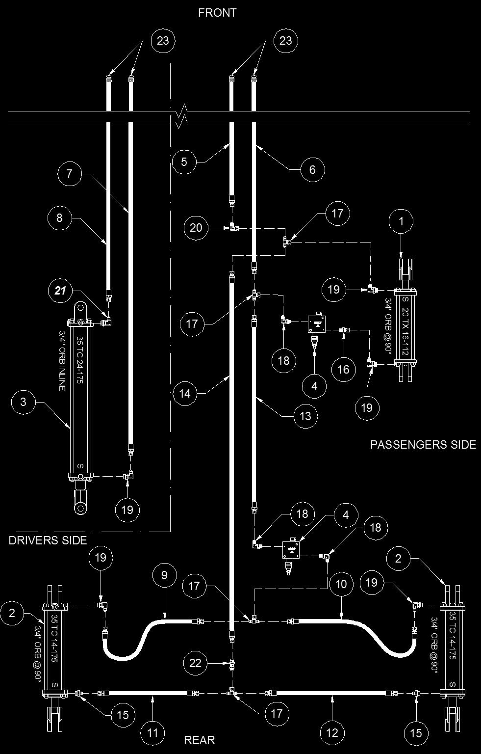
30 HYDRAULIC ASSEMBLY HYDRAULIC ASSEMBLY 23
31 HYDRAULIC ASSEMBLY ITEM # PART # DESCRIPTION HYDRAULIC ASSEMBLY TX Hydraulic Cylinder, 3/4 90 to Pin (Mon # ) THC Hydraulic Cylinder, 3/4 90º to Pin (Mon # ) TC Hydraulic Cylinder, 3/4 90º to Pin (Mon # ) In-Line Lock Valve (Superior # , Sun # SXCB-LAN-GNN) /8 Hose, 1/2 NPT M x 3/8 JIC Sw. F c/w Pioneer Tip ( ) /8 Hose, 1/2 NPT M x 3/8 JIC Sw. F c/w Pioneer Tip ( ) /8 Hose, 1/2 NPT M x 3/8 JIC Sw. F c/w Pioneer Tip ( ) /8 Hose, 1/2 NPT M x 3/8 JIC Sw. F c/w Pioneer Tip ( ) /8 Hose, 3/8 JIC Sw. F x 3/8 JIC Sw. F /8 Hose, 3/8 JIC Sw. F x 3/8 JIC Sw. F /8 Hose, 3/8 JIC Sw. F x 3/8 JIC Sw. F /8 Hose, 3/8 JIC Sw. F x 3/8 JIC Sw. F /8 Hose, 3/8 JIC Sw. F x 3/8 JIC Sw. F /8 Hose, 3/8 JIC Sw. F x 3/8 JIC Sw. F Adaptor, 1/2" ORB M x 3/8 JIC M Adaptor, 3/8 ORB M x 3/8 JIC Sw. F Tee, 3/8 JIC M (x2 Run) x 3/8 JIC Sw. F (Branch) Elbow, 3/8 ORB M x 3/8 JIC M Elbow, 1/2 ORB M x 3/8 JIC M Elbow, 3/8 JIC Sw. F x 3/8 JIC M Elbow, 1/2 ORB M x 3/8 M 90, Restricted Nipple, 3/8 JIC M x 3/8 JIC M, Bulkhead Pioneer Tip, 1/2 NPT F 24
 9.")
32 HUB BREAKDOWN CTD 812 HUB BEAKDOWN Drive In Stud & Wheel Nut ITEM # PART# DESCRIPTION Spindle, Bolt-in Style Ø2-1/2 x 11-3/4 long CTD Hub (Takes SE-17 Seal) Outer Cup, LM Inner Cup, DC17 Dust Cap Outer Bearing, Inner Bearing, SE-17 (For CTD-812 & CTD Hub) Castle Nut, NF, Pltd /16 x 1-3/4 Wheel Bolt (Not Shown) Spindle Washer, Plain /16 x 1-3/4 Cotter Pin, Plain CTD Hub Assembly /16 Wheel Nut (For CTD-812-1) /16 x 2-1/4 Wheel Stud (For CTD-812-1) 25
33 CYLINDER BREAKDOWN MONARCH 3-1/2 X 24 CYLINDER 35TC (3/4 ORB Inline) Riteway Part # Monarch Part # Check with parts prior to ordering ITEM # PART# DESCRIPTION Clevis Cap 3-1/2", 3/4 NF ORB Rod Cap 3-1/2", 3/4 ORB, 1-3/4" ID Piston 3-1/2 x 1- TL / TC Seal Hallite 605 Rod Ø1-3/4" Cylinder Tube, 3-1/2 x 24" - TL / TC Tie Rod, 5/8" x 24", NF, Gr.5 - TL / TC Cylinder Pin Ø1" x 3.37 for HP / COT Cotter Pin, 3/16 x 1-1/2 Hammer Lock, Pltd Socket Set Screw, 3/8" x 5/16, NF, Pltd Rod Clevis 1-1/2 x 1" - TL / TC /8 Hex Nut, NF, Gr.5, Black Piston Hex Nut, 1-1/4" ID, Gr.B Port Plug, 3/4", NF, Socket Head c/with O-Ring Seal Kit, RK 35L-175 Lion Hyd. Rep. Kit 26

34 CYLINDER BREAKDOWN MONARCH 3-1/2 X 14 CYLINDER 35THC (3/4 ORB 90 ) Riteway Part # Monarch Part # Check with parts man prior to ordering ITEM # PART# DESCRIPTION Clevis Cap 3-1/2-3/4 NF 90º Rod Cap 3-1/2-3/4 ORB, 1-3/43" ID Piston 3-1/2 x 1 - TL / TC Seal Hallite 605 Rod Ø1-3/4" x Cylinder Tube Tie Rod 5/8-14", NF, Gr.5, - TL / TC Cylinder Pin Ø1" x 3.37 for HP / COT Cotter Pin, 3/16 x 1-1/2 Hammer Lock, Pltd Socket Set Screw, 3/8 UNC x ½ KNUR Rod Clevis 1-1/4 ID x 1" /8 Hex Nut, NC, Gr.5, Black Piston Hex Nut 1-1/4 ID, Gr.B Port Plug 3/4, NF Socket Head c/with O-Ring Seal Kit, RK 35L-175 Lion Hyd. Rep. Kit 27

35 MONARCH 20 X 16 CYLINDER 20TX (3/4 ORB 90 ) Riteway Part # Monarch Part # DRAWING SHOWS PORTS IN LINE TO CYLINDER PINS CYLINDER BREAKDOWN Check with parts prior to ordering ITEM # PART# DESCRIPTION Clevis Cap /8 ORB- 1" Rod Cap /8" ORB - TX Piston TX Seal Hallite 605 Rod - 1-1/8"D Cylinder Tube x TX Tie Rod 5/16" TX - Washed Cylinder Pin Ø1" X 3.37" HP / COT Cotter Pin, 3/16 x 1-1/2 Hammer Lock Socket Set Screw, 3/8 UNC x ½ KNUR Rod Clevis 1 ID x 1" - TX /16 Hex Nut, NC, Gr.B, Black Plug 3/8-18 NPTF Dry Seal Seal Kit, RK 20L-112 Lion Hyd. Rep. Kit 28

36 SIDE WIND PARKING JACK lbs RITE WAY PART NUMBER SIDE WIND PARKING JACK BREAKDOWN Crank kit may not be available due to manufactures supplies ITEM # PART# DESCRIPTION Side Wind Crank Kit Gear Set Hitch Pin c/w Chain Screw Replacement Kit Inner Ram Assembly Capscrew - 1/4" x 3" UNC Lock Nut - 1/4" UNC Cover Body 29
37 ACRE METER LOCATION ACRE METER LOCATION ITEM # PART# DESCRIPTION ID Acre Meter Housing Model 4120 Acre Meter, Forester /2 x 1/2 Set Screw, NC, Black /2 x 4 Capscrew, NC, Gr. 5, Pltd /2 Nylon Lock Nut, NC, Pltd /2 Jam Nut, NC, Pltd /2 Plate Washer, NC, Pltd r1 Replaceable Drum Shaft (Ø2-7/16" x 14-3/4") To purchase an acre meter please contact Forster Industries, Toll Free # NOTE: Use Loc-Tite with jam nut when assembling to housing. DO NOT OVER TIGHTEN. 30

38 GRADE CHART GRADE CHART 31

39 TORQUE CHART TORQUE CHART 32
40 NOTES NOTES 33
FIXED HITCH LAND ROLLER. Operation & Maintenance Manual OPERATORS MANUAL & PART LIST
 FIXED HITCH LAND ROLLER Operation & Maintenance Manual OPERATORS MANUAL & PART LIST Contents SECTION 1 PAGE INTRODUCTION 1 MANUAL & EQUIPMENT DETAILS 2 SPECIFICATIONS 3 PRE-DELIVERY INSPECTION 4 SERVICE
RW 1200 ROCK WINDROWER. Table of Contents
 RITE WAY MFG. CO. LTD. P.O. Box 328 Imperial, Saskatchewan Canada, S0G 2J0 Ph: (306) 963-2180 Fax: (306) 963-2660 Web Site: www.ritewaymfg.com E-mail: info@ritewaymfg.com RW 1200 ROCK WINDROWER Table of
RITE WAY MFG. CO. LTD. P.O.
 CO. LTD. P.O. Box 328 Imperial, Saskatchewan Canada, S0G 2J0 Ph: (306) 963-280 Fax: (306) 963-2660 Web Site: www.ritewaymfg.com E-mail: info@ritewaymfg.com Table of Contents SPECIFICATIONS... WARNING...2
RITE WAY MFG. CO. LTD. P.O. Box 328 Imperial, Saskatchewan Canada, S0G 2J0 Ph: (306) Fax: (306) Web Site:
 Fax: (306) Web Site:") CO. LTD. P.O. Box 328 Imperial, Saskatchewan Canada, S0G 2J0 Ph: (306) 963-2180 Fax: (306) 963-2660 Web Site: www.ritewaymfg.com E-mail: info@ritewaymfg.com 28, 40, 50, 62 & 73 Table of Contents INTRODUCTION...
CO. LTD. P.O. Box 328 Imperial, Saskatchewan Canada, S0G 2J0 Ph: (306) 963-2180 Fax: (306) 963-2660 Web Site: www.ritewaymfg.com E-mail: info@ritewaymfg.com 28, 40, 50, 62 & 73 Table of Contents INTRODUCTION...
RITE WAY MFG. CO. LTD.
 P. O. Box 328 Imperial, Saskatchewan Canada, S0G 2J0 PH: (306) 963-2180 Web Site: www.ritewaymfg.com E-mail: info@ritewaymfg.com 33', 45', 55', 68' & 78' Solid Draft Arm Table of Contents INTRODUCTION...
MODEL 328 (306) : 8190 JUMBO HEAVY HARROW
 : 8190 JUMBO HEAVY HARROW") P. O. Box 328 Imperial, Saskatchewan Canada, S0G 2J0 PH: (306) 963-2180 Web Site: www.ritewaymfg.com E-mail: info@ritewaymfg.com 90 Solid Draft Arm Table of Contents INTRODUCTION... 1 SPECIFICATIONS...
P. O. Box 328 Imperial, Saskatchewan Canada, S0G 2J0 PH: (306) 963-2180 Web Site: www.ritewaymfg.com E-mail: info@ritewaymfg.com 90 Solid Draft Arm Table of Contents INTRODUCTION... 1 SPECIFICATIONS...
HIGH SPEED COMPACT DISC (HCD-32) Operation & Maintenance Manual OPERATORS MANUAL & PART LIST
 Operation & Maintenance Manual OPERATORS MANUAL & PART LIST") HIGH SPEED COMPACT DISC (HCD-32) Operation & Maintenance Manual OPERATORS MANUAL & PART LIST Quick Start Guide Hydraulic Connections to Tractor Yellow Lifting/lowering main frame and packers Black Disc
HIGH SPEED COMPACT DISC (HCD-32) Operation & Maintenance Manual OPERATORS MANUAL & PART LIST Quick Start Guide Hydraulic Connections to Tractor Yellow Lifting/lowering main frame and packers Black Disc
SAFETY. Hitchpole, centre frame 1. Centre frame wheels & roller 3. Centre & wing frames 5. Wing frame wheels & roller 9.
 MANUAL Hitchpole, centre frame 1 Centre frame wheels & roller 3 Centre & wing frames Wing frame wheels & roller 9 Hydraulics 11 Clearance lights 13 Operations 1 Safety, warranty 1 SAFETY Industrial Drive,
LAND MAINTENANCE REPAIR PARTS MANUAL BUSH HOG MODEL: 307 SECTION: 16
 BUSH HOG LAND MAINTENANCE REPAIR S MANUAL MODEL: 0 SECTION: P.O. Box 0 Selma, AL 0-0 () - () -00 Parts Ordering -00-0- Fax -00-- www.bushhog.com BUSH HOG / LAND MAINTENANCE REPAIR S MANUAL SEPTEMBER, 0
PARTS MANUAL. HD4SR and 12SR Auto Align Bale Skoop to 2017 K
 PARTS MANUAL 1998 to 2017 HD4SR and 12SR Auto Align Bale Skoop K34991-04 Table of Contents Section 1: Parts Breakdown...1-1 Bale Skoop Final Assembly... 1-2 Loader Assembly... 1-4 12SR - Grab Hook Assembly
EURO REEL
 Date Purchased Machine Serial No. Options The key number system in this parts book is arranged as follows: Please order parts by number - Key numbers with two circles denotes main assemblies. - Key numbers
BUSH HOG LAND MAINTENANCE REPAIR PARTS MANUAL MODEL: TD-1100 SECTION: 66
 BUSH HOG LAND MAINTENANCE REPAIR S MANUAL MODEL: TD-00 SECTION: 0 Griffin Ave. Selma, AL 0 () - () -00 Parts Ordering -00-0- Fax -00-- www.bushhog.com BUSH HOG/ LAND MAINTENANCE REPAIR S MANUAL JUNE, 00
4200 & 6200 Owner s Manual & Parts Book
 00 & 00 Owner s Manual & Parts Book Purchase Date Serial Number Model Number Tractor Model PN: - Dealer Date --0 Description Page To The Owner & Maintenance Safety Precautions & Torque Specifications Skid
FLX15 ROTARY CUTTERS PARTS MANUAL ATENCIÓN! LEA EL INSTRUCTIVO
 Published: /0 FLX ROTARY CUTTERS S/N A00000 A0000 inclusive PARTS MANUAL Part No. A0-00P An Operators Manual with IMPORTANT Safety, Assembly, Operation and Maintenance information was packaged with this
VR482 Hay Rake OPERATOR & PARTS MANUAL. Last Updated: May 12, 2014
 VR482 Hay Rake OPERATOR & PARTS MANUAL Last Updated: May 12, 2014 Bridgeview Manufacturing Inc. P.O. Box 4 Gerald, SK S0A 1B0 (306) 745-2711 www.bridgeviewmanufacturing.com bmi@sasktel.net Your Authorized
BUSH HOG LAND MAINTENANCE REPAIR PARTS MANUAL MODEL: 405 / 406 SECTION: 17
 BUSH HOG LAND MAINTENANCE REPAIR S MANUAL MODEL: 0 / 0 SECTION: 0 Griffin Ave. Selma, AL 0 () - () -00 Parts Ordering -00-0- Fax -00-- www.bushhog.com BUSH HOG/ LAND MAINTENANCE REPAIR S MANUAL SEPTEMBER,
KONGSKILDE 9200 DF Vertical Tillage - Assembly/Parts
 KONGSKILDE 9200 DF Vertical Tillage - Assembly/Parts Kongskilde 9200 *Model may not be exactly as shown. Kongskilde reserves the right to make changes to product designs and specifications without notice
450 & Slant Top Owner s Manual & Parts Book
 0 & 0 - Slant Top Owner s Manual & Parts Book Purchase Date Serial Number Model Number Tractor Model PN: - Dealer Date -- Contents Description Page To The Owner & Maintenance Safety Precautions & Torque
TWIN ROTARY RAKE PARTS BOOK MODEL
 TWIN ROTARY RAKE PARTS BOOK MODEL 2650 17.01135 This parts book is furnished for your convenience only. All parts must be purchased through an authorized dealer. Call us for a dealer near you. Issue Date:
WX540-LEU Trailer Log Splitter Parts Manual
 EMB Manufacturing Inc. Boomer Line St. Clements, On N0B M0 Canada Ph: (9) 99-98 Fax: (9) 99- www.embmfg.com WX0-LEU Trailer Log Splitter Parts Manual S/N E9USES00 & After Refer to the operators manual
WX540-LEU Trailer Log Splitter Parts Manual
 EMB Manufacturing Inc. Boomer Line St. Clements, On N0B M0 Canada Ph: (59) 99-98 Fax: (59) 99- www.embmfg.com WX50-LEU Trailer Log Splitter Parts Manual S/N E9USXDS000 & After Refer to the operators manual
KONGSKILDE 8200 DF Field Cultivator - Assembly/Parts
 KONGSKILDE 8200 DF Field Cultivator - Assembly/Parts Kongskilde 8200 Models 768236901 8236 Field Cultivator (36.5') 768238901 8238 Field Cultivator (38.5') 768240901 8240 Field Cultivator (40.5') 768242901
BUSH HOG LAND MAINTENANCE REPAIR PARTS MANUAL MODEL: 280 SERIES SECTION: 59
 BUSH HOG LAND MAINTENANCE REPAIR S MANUAL MODEL: 0 SERIES SECTION: P.O. Box 0 Selma, AL 0-0 () - () -00 Parts Ordering -00-0- Fax -00-- www.bushhog.com BUSH HOG/ LAND MAINTENANCE REPAIR S MANUAL JUNE,
LIMITED WARRANTY DISCLAIMER OF IMPLIED WARRANTIES & CONSEQUENTIAL DAMAGES
 Published 08/15 LIMITED WARRANTY Bush Hog warrants to the original purchaser of any new Bush Hog equipment, purchased from an authorized Bush Hog dealer, that the equipment be free from defects in material
PARTS CATALOG FOR. Mud Hog System II & System III 2-Speed Rear Wheel Drive FOR JOHN DEERE 9960, 9965 & 9970 COTTON PICKERS
 PARTS CATALOG FOR Mud Hog System II & System III 2-Speed Rear Wheel Drive FOR JOHN DEERE 9960, 9965 & 9970 COTTON PICKERS Mud Hog Model Numbers Tread Center MH System 9960 9965 & 9970 JD47601 JD47651 82-90
BUSH HOG LAND MAINTENANCE REPAIR PARTS MANUAL MODEL: 3414 SECTION: 67
 BUSH HOG LAND MAINTENANCE REPAIR S MANUAL MODEL: SECTION: 0 Griffin Ave. Selma, AL 0 () - () -00 Parts Ordering -00-0- Fax -00-- www.bushhog.com BUSH HOG/ LAND MAINTENANCE REPAIR S MANUAL July, 0 ROTARY
John Deere TLS TLS Tractors MANUAL
 John Deere 600-00 6-6 TLS - TLS Tractors MANUAL 00 John Deere 600-00 6-6 TLS - TLS Tractors Blade, pivot frame Hydraulics Tractor fit-up, mounting Operation, maintenance Previous hydraulic system Attachments
SOIL CONDITIONER OPERATORS MANUAL TF5S
 TF5S OPERATORS MANUAL Rev. 4.3.2017 SOIL CONDITIONER J. & M. Mfg. Co., Inc. 284 Railroad Street - P.O. Box 547 Fort Recovery, OH 45846 Ph: (419) 375-2376 Fax: (419) 375-2708 www.jm-inc.com Table Of Contents
530B ECOLO-TIGER MULCH CHISEL WARNING AND TAILIGHT KIT ECOLO-TIGER 530B
 04-01 WARNING AND TAILIGHT KIT ECOLO-TIGER 530B 04-01 WARNING AND TAILIGHT KIT ECOLO-TIGER 530B 2 27602311 1 HARNESS, WIRE, Front 3 27602221 1 HARNESS, WIRE, Rear (530B) 4 27602202 2 LIGHT ASSY., Red 5
PARTS MANUAL BALE KING V-RAKE VR810 GREEN AND YELLOW ITEM NUMBERS
 PARTS MANUAL BALE KING V-RAKE VR810 GREEN AND YELLOW ITEM NUMBERS MANUFACTURED BY: BRIDGEVIEW MANUFACTURING INC. P.O. BOX 4 GERALD, SASK. CANADA S0A 1B0 PHONE: (306) 745-2711 FAX: (306) 745-3364 TABLE
PARTS MANUAL SECTION 105 FLEX WING ROTARY CUTTER. Published 09/14
 8 FLEX WING ROTARY CUTTER Published 09/ PARTS MANUAL SECTION 0 An Operator s Manual was shipped with the equipment. The Operator s Manual is an integral part of the safe operation of this machine and must
Case STX/NH TJ
 Case STX/NH TJ 0-0 Tractors MANUAL Case STX/NH TJ 0-0 Tractors Blades, pivot frames Tractor fit-up Dlock, mounting Hydraulics Operation, maintenance Safety, warranty Industrial Drive, Box 0 Regina, Sask.
JOHN DEERE 9970 COTTON PICKERS
 PARTS CATALOG FOR Mud Hog System II Rear Wheel Drive FOR JOHN DEERE 9970 COTTON PICKERS Mud Hog Model Numbers Tread Center OEM Aftermarket JD40005 JD47655 82, 90, 94, 106 TUTHILL Drive Systems 9098 West
AG PRO SS Owner s Manual & Parts Book
 AG PRO SS Owner s Manual & Parts Book Purchase Date Serial Number Model Number Tractor Model Dealer PN: 63-19460 SN: 10204276-... Date 1-10-2017 Description Contents Page To The Owner, Maintenance, Safety
PARTS MANUAL THIS PAGE INTENTIONALLY LEFT BLANK. Ag-Bag International, Ltd. G7000 June Appendix A
 The parts manual is organized into groups, it is designed to make the locating of parts easier. The exploded drawings also show assembly paths. All parts listed are available from your authorized Ag-Bag
I-110 PARTS MANUAL Updated 3/21/01
 I-110 PARTS MANUAL Updated 3/21/01 Ashland Industries Inc. Hwy. 13 South P.O. Box 717 Ashland, WI. 54806 877-634-4622 Toll Free - phone 715-682-4622 phone 715-682-9717 fax www.ashlandind.com MODEL I-100,
2720/12720 PARTS MANUAL 72A SECTION FLEX WING ROTARY MOWER
 0/0 This Manual applies to models 0 and 0 that use a blade pan which measures. blade hole center to blade hole center. Also blades measure 8. from hole center to blade tip. See Section if these dimensions
K -HART. Coulter. Owner s Manual Model 1600, 1620, 1601, 1602, 1603
 K -HART INDUSTRIES LTD. www.khartindustries.com Coulter Owner s Manual Model 600, 620, 60, 602, 603 Box 520 Elrose, Saskatchewan S0L 0Z0 Canada Ph: (306)378-2258 Fax: (306)378-2926 E-mail:sales@khartindustries.com
BALE KING VR483. Hay Rake. Operator's & Parts Manual. Last Updated: April 27, Bridgeview Manufacturing Inc.
 BALE KING VR483 Hay Rake Operator's & Parts Manual Last Updated: April 27, 2015 P.O. Box 4 Gerald, Saskatchewan, Canada S0A 1B0 Phone: 1-306-745-2711 Fax: 1-306-745-3364 Email: bmi@sasktel.net www.bridgeviewmanufacturing.com
Mulching and Finishing Mowers MP and FP
 Mulching and Finishing Mowers MP and FP Parts Manual Locke Turf 0 Highway E, Opp, Alabama, () -00 Transport Wheel, Tire & Spindle MP and FP ALPHABETICAL INDEX CONTENTS PAGE 00 Hydraulic Cylinder (Rear)
Extreme Duty Grapple (Rock, Skeleton, Scrap & Tine) Operation and Maintenance Manual
 Operation and Maintenance Manual") Extreme Duty Grapple (Rock, Skeleton, Scrap & Tine) Operation and Maintenance Manual Revision Date: May 12, 2017 Skid Pro PO Box 982 Alexandria, MN 56308 Toll Free: 877-378-4642 www.skidpro.com TABLE OF
Extreme Duty Grapple (Rock, Skeleton, Scrap & Tine) Operation and Maintenance Manual Revision Date: May 12, 2017 Skid Pro PO Box 982 Alexandria, MN 56308 Toll Free: 877-378-4642 www.skidpro.com TABLE OF
Case IH MX Tractors MANUAL
 Case IH MX - 0 Tractors MANUAL Case IH MX - 0 Tractors Blade, pivot frame 1 Hydraulics Tractor fit-up, mounting Operation, maintenance Attachments 11 Safety, warranty 1 Industrial Drive, Box 0 Regina,
PARTS MANUAL VR 1214 BALE KING V-RAKE GREEN AND YELLOW NUMBERS
 PARTS MANUAL VR 1214 BALE KING V-RAKE GREEN AND YELLOW NUMBERS MANUFACTURED BY: BRIDGEVIEW MANUFACTURING INC. P.O. BOX 4 GERALD, SASK. CANADA S0A 1B0 PHONE: (306) 745-2711 FAX: (306) 745-3364 TABLE OF
New Holland & 8670A A Buhler Genesis 2145/2160/2180/2210
 New Holland 0-90 0A - 90A Buhler Genesis 1/10/10/ Tractors MANUAL 191 New Holland 0-90 0A - 90A Buhler Genesis 1/10/10/ Tractors Blade, pivot frame 1 Hydraulics Tractor fit-up, mounting Operation, maintenance
BALE KING GT40 Grain Feeder Operator's & Parts Manual Last Update: November 20, 2014 Bridgeview Manufacturing Inc - 1 -
 BALE KING GT40 Grain Feeder Operator's & Parts Manual Last Update: November 20, 2014 Bridgeview Manufacturing Inc - 1 - Your Authorized Dealer: Your Serial Number: The Serial Number is located on the tank.
11 ½" MODEL SINGLE CHAIN CONVEYOR
 11 ½" MODEL SINGLE CHAIN CONVEYOR USER S MANUAL 11 ½" Chain conveyor Revision 2011-05-31 2 CONTENTS WARRANTY...3 FOREWORD...4 SAFETY PRECAUTIONS...5 ASSEMBLY INSTRUCTIONS...6 SPECIFICATIONS...6 ASSEMBLING
PULLDOZER 1800/1800XL/2400/2400XL
 PULLDOZER 1800/1800XL/2400/2400XL Assembly and Parts Manual Bridgeview Manufacturing Inc. P.O. Box 4 Gerald, SK S0A 1B0 (306) 745-2711 www.bridgeviewmanufacturing.com bmi@sasktel.net 2 1. Component Information
PARTS CATALOG FOR. Mud Hog Rear Wheel Drive FOR. MF 9540/9550/9560, CAT 540C/550C/560C, Gleaner A540/A560, Fendt 6450R/9480R COMBINES
 PARTS CATALOG FOR Mud Hog Rear Wheel Drive FOR MF 9540/9550/9560, CAT 540C/550C/560C, Gleaner A540/A560, Fendt 6450R/9480R COMBINES Mud Hog Model Number: AG9896 A Product of Tuthill Drive Systems P.O.
BUSH HOG LAND MAINTENANCE REPAIR PARTS MANUAL MODEL: 280 SERIES SECTION: 59
 BUSH HOG LAND MAINTENANCE REPAIR S MANUAL MODEL: 0 SERIES SECTION: 0 Griffin Ave. Selma, AL 0 () () 00 Parts Ordering 00 0 Fax 00 www.bushhog.com BUSH HOG/ LAND MAINTENANCE REPAIR S MANUAL October, 0 0
OWNER S MANUAL Z SERIES TRACKS. Rev. 355_05
 OWNER S MANUAL Z SERIES TRACKS Rev. 355_05 LOEGERING 800-373-5441 15514 37 th Street SE 701-347-5441 Casselton, ND 58012 USA Fax: 701-347-4323 E-Mail: lmi@loegering.com Internet: www.loegering.com Loegering
MidCap Rotary Rake. Illustrated Parts Breakdown
 MidCap Rotary Rake Illustrated Parts Breakdown Page Page Page Page Page Page Page Page Page Page 0 Page Page Page Page Page Page Page Page Page Main Frame Transport Wheel Assembly Lift Arm Assembly Main
MODEL I-900 SCRAPER INDEX
 I-900 PARTS MANUAL Ashland Industries Inc. Hwy. 13 South P.O. Box 717 Ashland, WI. 54806 877-634-4622 Toll Free - phone 715-682-4622 phone 715-682-9717 fax www.ashlandind.com MODEL I-900 SCRAPER HOW TO
Model 35 PARTS MANUAL
 Model 35 PARTS MANUAL Version 3-2007 Ashland Industries Inc. 1115 Rail Drive P.O. Box 717 Ashland, WI. 54806 Ph: 877-634-4622 Toll Free Ph: 715-682-4622 Fx: 715-682-9717 www.ashlandind.com Model 35 Scraper
Parts Manual FRONT-FOLD BOOMS MODELS 80, 90 & 100 HYDRAULIC FOR TA1200 & TA1600 SPRAYERS. Serial Number B & Higher. Part No.
 Parts Manual FRONT-FOLD BOOMS MODELS 80, 90 & 100 HYDRAULIC FOR TA1200 & TA1600 SPRAYERS Serial Number B30970200 & Higher Part No. 408920 Front-Fold Booms 80 / 90 / 100 Introduction Foreward This symbol
MODEL 5120 Tire Repair Station
 MODEL 5120 Tire Repair Station 00-0049 Installation, Operation & Repair Parts Information Branick Industries, Inc. 4245 Main Avenue P.O. Box 1937 Fargo, North Dakota 58103 REV01182017 P/N: 81-0058G CAUTION
BUSH HOG LAND MAINTENANCE REPAIR PARTS MANUAL MODELS: RPM & RPM SECTION: 79
 BUSH HOG LAND MAINTENANCE REPAIR S MANUAL MODELS: -0 RPM & -000 RPM SECTION: 9 0 Griffin Ave. Selma, Al. 0 () - () -00 Parts Ordering -00-0- Fax -00-- www.bushhog.com April, 0 BUSH HOG/ LAND MAINTENANCE
PARTS MANUAL 3510, 3510-O, SECTION ROTARY MOWER
 , -O, ROTARY MOWER Published 0/ S MANUAL SECTION An Operator s Manual was shipped with the equipment. The Operator s Manual is an integral part of the safe operation of this machine and must be maintained
Post Driver Attachment
 Attachment (Shown with Optional Power Cell Rotator) Models - 600, 850 Safety Instructions This safety alert symbol indicates important safety messages in this manual. When you see this symbol, carefully
OWNER S GUIDE 8A DURALIFT II 13,200 LB. CAPACITY. Link Mfg. Ltd th St. N.E. Sioux Center, IA USA
 OWNER S GUIDE 8A000715 DURALIFT II 13,200 LB. CAPACITY Link Mfg. Ltd. 223 15th St. N.E. Sioux Center, IA USA 51250-2120 www.linkmfg.com QUESTIONS? CALL CUSTOMER SERVICE 1-800-222-6283 DEALER / INSTALLER:
New Holland TM CASE MXM
 New Holland TM - 90 CASE MXM - 90 Tractors MANUAL New Holland TM - 90 CASE MXM - 90 Tractors Blade, pivot frame Hydraulics Tractor fit-up, mounting Operation, maintenance 9 Previous hydraulic system Attachments
GRAIN DECK BELT CONVEYOR PARTS LIST SERIAL NOS
 GRAIN DECK BELT CONVEYOR PARTS LIST SERIAL NOS. 112000-115499 1 DISCHARGE ASSEMBLY - GRAIN BELT DRIVE OVER CONVEYOR SERIAL NOS. 112000-115499 2 REF # PART NO. DESCRIPTION QTY 1 C200760 Discharge Weldment
FX140 & FX140R Skidding Winch Parts Manual
 EMB Manufacturing Inc. 4144 Boomer Line St. Clements, On N0B 2M0 Canada Ph: (519) 699-9283 Fax: (519) 699-4146 www.wallensteinequipment.com FX140 & FX140R Skidding Winch Parts Manual S/N 514094 & After
Parts Book 612N, 812N, 642N, 842N, 862N 714NT, 814NT, 742NT, 842NT, 862NT
 Parts Book 612N, 812N, 642N, 842N, 862N 714NT, 814NT, 742NT, 842NT, 862NT Wishek Mfg. LLC 112 South 2nd Street PO Box 185 Wishek, ND 58495 (701) 452-2449 www.wishekmfg.com WARRANTY/ PARTS RETURN POLICY
OPERATION AND MAINTENANCE MANUAL WASP, Inc. United Airlines Shock Mount Cargo Cart Model No. A03439D
 OPERATION AND MAINTENANCE MANUAL WASP, Inc. United Airlines Shock Mount Cargo Cart Model No. A03439D WASP RECORD OF REVISIONS REV. ISSUE DATE BY REV. ISSUE DATE BY NO. DATE INSERTED NO. DATE INSERTED Original
TT4101 Rotary Tedder
 TT Rotary Tedder 0//0 Illustrated Parts Breakdown Page Page Page Page Page Page Page Page Page Page Page Tongue Assembly S/N S/N - Tongue Assembly S/N + Main Frame S/N - Main Frame S/N to Main Frame S/N
WX540 SERIES Trailer Log Splitter Parts Manual Starting with S/N s WX540L: 2E9US1115ES to 2E9US1115ES WX540: to
 EMB Manufacturing Inc. 4144 Boomer Line St. Clements, On N0B 2M0 Canada Ph: (519) 699-9283 Fax: (519) 699-4146 www.wallensteinequipment.com WX540 SERIES Trailer Log Splitter Parts Manual Starting with
WP235 Wood Processor Parts Manual
 EMB Manufacturing Inc. 4144 Boomer Line St. Clements, On N0B 2M0 Canada Ph: (519) 699-9283 Fax: (519) 699-4146 www.embmfg.com WP235 Wood Processor Parts Manual Starting with S/N 680035 Refer to the operators
MODEL EF Full Circle Tire Spreader
 MODEL EF Full Circle Tire Spreader Installation, Operation & Repair Parts Information Branick Industries, Inc. 4245 Main Avenue P.O. Box 1937 Fargo, North Dakota 58103 REV. 062917 P/N: 81-0050C CAUTION
OWNER S MANUAL. LOEGERING th Street SE Casselton, ND USA Fax:
 OWNER S MANUAL TRAIL BLAZERS and D SERIES TRACKS LOEGERING 800-373-5441 15514 37 th Street SE 701-347-5441 Casselton, ND 58012 USA Fax: 701-347-4323 E-Mail: lmi@loegering.com Internet: www.loegering.com
PARTS MANUAL SECTION R1, 2215RR1-540 RPM 12215R1, 12215RR1-1000RPM FLEX WING ROTARY CUTTER. Published 07/16
 225R, 225RR - 50 RPM 225R, 225RR - 000RPM FLEX WING ROTARY CUTTER Published 07/6 PARTS MANUAL SECTION 3 An Operator s Manual was shipped with the equipment. The Operator s Manual is an integral part of
Highline Manufacturing TopGun 1999 Page 1 A. TABLE OF CONTENTS... 1
 Highline Manufacturing TopGun 1999 Page 1 A. Table of Contents A. TABLE OF CONTENTS... 1 B. ASSEMBLY & INSTALLATIONS... 3 1. FLAIL DRUM ASSEMBLY... 3 2. FLAIL DRUM INSTALLATION... 4 3. FEED ROLLER ASSEMBLY...
CRUSTBUSTER OWNER / OPERATOR MANUAL
 CRUSTBUSTER OWNER / OPERATOR MANUAL MODEL # CB-1 CRUSTBUSTER Manufactured by: LEWIS BROTHERS MANUFACTURING, INC. Post Office Box 146 Baxley, GA 31513 Tel: (912) 367-4651 Fax: (912) 367-3958 5-2-17 1 INTRODUCTION
3308, 3308SH PARTS MANUAL SECTION ROTARY MOWER
 0, 0SH ROTARY MOWER Published / PARTS MANUAL SECTION 0 An Operator s Manual was shipped with the equipment. The Operator s Manual is an integral part of the safe operation of this machine and must be maintained
OPERATOR'S MANUAL & PARTS CATALOG 12 TON RUNNING GEAR
 Unverferth Grain Handling Systems OPERATOR'S MANUAL & PARTS CATALOG 1 TON RUNNING GEAR Model RGE- Unverferth Manufacturing Co., Inc. Box 7 Kalida, OH 8 Part No. 00 PH: 1-- FAX: 1--8 www.unverferth.com
4050A. Tire Changer. Parts Identification. For servicing single piece automotive and most light truck tire/wheel assemblies
 4050A Tire Changer For servicing single piece automotive and most light truck tire/wheel assemblies Parts Identification READ these instructions before placing unit in service KEEP these and other materials
KONGSKILDE 9100 Vertical Tillage - Spare Parts List
 KONGSKILDE 900 Vertical Tillage - Spare Parts List Kongskilde 900 Models 000000 9 Vertical Tillage (') 000000 9 Vertical Tillage (') 7990 9 Vertical Tillage (.') *Model may not be exactly as shown. Kongskilde
Soil Conditioners OPERATORS MANUAL. TF2 serial #2250 and higher TF212 TF215
 TF2 serial #2250 and higher TF212 TF215 OPERATORS MANUAL Rev.3.21.2018 Soil Conditioners J. & M. Mfg. Co., Inc. 284 Railroad Street - P.O. Box 547 Fort Recovery, OH 45846 Ph: (419) 375-2376 Fax: (419)
2820/12820 SECTION 103. This Manual applies to Models: 2820R1, 12820R1, 12820S1 2820RR1, 12820RR1, 12820SR1 FLEX WING ROTARY CUTTER/SHREDDER
 0/0 This Manual applies to Models: 0R, 0R, 0S 0RR, 0RR, 0SR FLEX WING ROTARY CUTTER/SHREDDER Published 0/ PARTS MANUAL SECTION 0 An Operator s Manual was shipped with the equipment. The Operator s Manual
TT4100 Rotary Tedder
 TT0 Rotary Tedder Serial numbers 0 and higher Illustrated Parts Breakdown Page Page Tongue Assembly S/N - Tongue Assembly S/N to Page Page Page Page Page Tongue Assembly S/N to Tongue Assembly S/N + Main
4750 Drill. Repair Parts
 4750 Drill Repair Parts #615997-2016 Identification Your CrustBuster drill is identified by a Serial Number and Model Number. Record these numbers in the spaces provided in this manual and refer to them
-HART. Packer Systems 20 Series
 -HART INDUSTRIES LTD. www.khartindustries.com Packer Systems Series Owners Manual Box 5 Elrose, Saskatchewan SL Z Canada Ph: (36)378-58 Fax: (36)378-96 E-mail:sales@khartindustries.com In Australia: DIRECT
-HART. Packer Systems 30 Series
 -HART INDUSTRIES LTD. www.khartindustries.com Packer Systems 3 Series Owners Manual Box 5 Elrose, Saskatchewan SL Z Canada Ph: (36)378-58 Fax: (36)378-96 E-mail:sales@khartindustries.com In Australia:
Drive End Bracket & Bearing. Drive End Bracket. Tandem Axle # #865733
 Drive End Bracket & Bearing #865089 1 06409700 1" Lock Collar 2 865733 Drive Bracket w/ Bearing 3 310037 End Drive Shaft Drive End Bracket #865733 1 03003100 Bearing 1" w/snap Ring 2 957795 Drive End Bracket
WP865 Wood Processor Parts Manual
 EMB Manufacturing Inc. 4144 Boomer Line St. Clements, On N0B 2M0 Canada Ph: (519) 699-9283 Fax: (519) 699-4146 www.wallensteinequipment.com WP865 Wood Processor Parts Manual S/N 2E9US1115FS660079 2E9US1115FS660139
DEBRIS BLOWER 2613 BLOWER ASSEMBLY PARTS CATALOG MODEL NO & UP. The TORO Company All Rights Reserved. FORM NO Rev.
 FORM NO. 01-505-0440 Rev. D MODEL NO. 44520-20101 & UP PARTS CATALOG DEBRIS BLOWER 2613 Part 1 61-005-0073 Hitch & Lower Housing 1 2 61-005-0121 Fan Housing 1 3 61-005-0061 Fan Assembly 1 4 01-113-0070
Operator s/parts Manual
 Operator s/parts Manual 3-Point Solid Stand Drills Pull Hitch Package Manufacturing, Inc. P.O. Box 5060 Salina, Kansas 67402-5060! Read the operator s manual entirely. When you see this symbol, the subsequent
BX7322 Adventurer Tow Bar Operator Manual & Installation Instructions
 Please visit www.blueox.com for the latest version of these installation instructions. BX7322 Operator Manual & Installation Instructions Serial Number (5,000 lb) 2 Inch Coupler 292-1263 Rev J Page 1 of
I-130 XL PARTS MANUAL Introduced 4/01/01
 I-130 XL PARTS MANUAL Introduced 4/01/01 Ashland Industries Inc. Hwy. 13 South P.O. Box 717 Ashland, WI. 54806 877-634-4622 Toll Free - phone 715-682-4622 phone 715-682-9717 fax www.ashlandind.com MODEL
Spike Tooth Harrow STH P Parts Manual. Copyright 2017 Printed 06/30/17
 Spike Tooth Harrow STH2024 30897 322-315P Parts Manual Read the Operator's Manual entirely. When you see this symbol, the subsequent instructions and warnings are serious - follow without exception. Your
12-20 (V6) - AG PRO PLUS
 - AG PRO PLUS") 12-20 (V6) - AG PRO PLUS Owner s Manual & Parts Book Purchase Date Serial Number Model Number Tractor Model Dealer PN: 6-18817 Date -17-201 Contents Description Page To The Owner, Warning, Maintenance
12-20 (V6) - AG PRO PLUS Owner s Manual & Parts Book Purchase Date Serial Number Model Number Tractor Model Dealer PN: 6-18817 Date -17-201 Contents Description Page To The Owner, Warning, Maintenance
EASY DUMP RD3100 / RD3106 (Standard)-(60/40 Split)-(60/40 Divider)- (70/30 Split with Bayne) USER S MANUAL
-(60/40 Split)-(60/40 Divider)- (70/30 Split with Bayne) USER S MANUAL") EASY DUMP RD3100 / RD3106 (Standard)-(60/40 Split)-(60/40 Divider)- (70/30 Split with Bayne) USER S MANUAL *** Important *** Read User s Manual Completely Prior to Operating Par-Kan Company Phone: 1-800-291-5487
EASY DUMP RD3100 / RD3106 (Standard)-(60/40 Split)-(60/40 Divider)- (70/30 Split with Bayne) USER S MANUAL *** Important *** Read User s Manual Completely Prior to Operating Par-Kan Company Phone: 1-800-291-5487
BANANA PEEL OWNER'S GUIDE # /98 $1.00
 BANANA PEEL OWNER'S GUIDE #1880 /98 $1.00 ILLUSTRATED PARTS BREAKDOWN ITEM PARJff DESCRIPTION QTY. ITEM PART# DESCRIPTION 1. 19171 SCREW #10-3 X 3/8 RHMS. 1863 FENDER B/P 3 3. 18306 FENDER B/P BRACE.
ALUMINUM & STEEL CAR CARRIERS
 OWNER'S MANUAL ALUMINUM & STEEL CAR CARRIERS INSTALLATION, OPERATION, MAINTENANCE & PARTS NOTE: MANUAL including SPECIFICATIONS, subject to change without notice All ratings specified are based on structural
HT46X Rotary Tedder. Illustrated Parts Breakdown. Center Section
 HTX Rotary Tedder Illustrated Parts Breakdown Page Page Page Page Page Page Page Page Page Page 0 Page Center Section Hydraulics Outer Wing Assembly Center Bolted Components Tine Rotor and Hardware Tilt
John Deere Tractors MANUAL
 John Deere 800-820 Tractors MANUAL 202 John Deere 800-820 Tractors Blade, pivot frame Cylinders & Hydraulics Main Frame, Brackets, Mounting Safety, Operation, Maintenance 9 Attachments Warranty 2 22 Industrial
Soil Conditioners OPERATORS MANUAL TF2 TF212 TF215. serial #2250 and higher
 TF2 TF212 TF215 serial #2250 and higher OPERATORS MANUAL Rev. 3.25.2015 Soil Conditioners J. & M. Mfg. Co., Inc. 284 Railroad Street - P.O. Box 547 Fort Recovery, OH 45846 Ph: (419) 375-2376 Fax: (419)
FRONT-FOLD BOOMS MODELS 80, 90 & 100 HYDRAULIC
 FRONT-FOLD BOOMS MODELS 80, 90 & 100 HYDRAULIC FOR TA1200, TA1600 & TA2400 SPRAYERS Serial Number B26720100 & Higher Part No. 407525 Front-Fold Booms 80 / 90 / 100 Introduction Foreward This symbol identifies
TABLE OF CONTENTS DESCRIPTION. Safety Instructions & Safety Sign Locations Operating Instructions Assembly Instructions...
 TABLE OF CONTENTS DESCRIPTION PAGE Warranty... 1 Safety Instructions & Safety Sign Locations... 2 Operating Instructions... 3 Assembly Instructions... 5 500 & 600 Snowblower Drawings... 8 500 & 600 Snowblower
OPERATION AND MAINTENANCE MANUAL WASP, Inc. 757 Towbar Model No. A01568D
 OPERATION AND MAINTENANCE MANUAL WASP, Inc. 757 Towbar Model No. A01568D WASP RECORD OF REVISIONS REV. ISSUE DATE BY REV. ISSUE DATE BY NO. DATE INSERTED NO. DATE INSERTED Original May 19/97 001 June 10/03
INSTALLATION MANUAL. CNH 5088, 6088, 7088 and 5130, 6130, 7130
 INSTALLATION MANUAL FOR Mud Hog Rear Wheel Drive FOR CNH 5088, 6088, 7088 and 5130, 6130, 7130 COMBINES Mud Hog Model Number: CNH42005 A Product of Tuthill Drive Systems P.O. Box 600 Brookston, Indiana