PULLDOZER 1800/1800XL/2400/2400XL
|
|
|
- Silas Perkins
- 5 years ago
- Views:
Transcription


1 PULLDOZER 1800/1800XL/2400/2400XL Assembly and Parts Manual Bridgeview Manufacturing Inc. P.O. Box 4 Gerald, SK S0A 1B0 (306) bmi@sasktel.net


2 2 1. Component Information (2400/1800) NOTE: ID Numbers and weights shown as 2400/1800, where different. Blade Weldment Main Frame Weldment 20743/ /20419 Weight = 10600/7200 lb Weight = 3800/3000 lb Hitch Weldment 20742/20422 Weight = 1700/1800 lb Axle Weldment 20745/20420 Weight = 5600/3000 lb Trencher Hitch Weldment 22107/22176 Weight = 2000/2100 lb Trencher 22013/22204 Weight = 1600/1100 lb Axle Collar Weldment Flasher Light Weldment 23339


3 3 Lift Cylinder Safety Lock Weldment Tilt Cylinder Safety Lock Weldment Blade Pin Weldment Trencher Safety Pin Trencher Depth Indicator Bracket Trencher Depth Indicator Arm Trencher Depth Indicator Linkage Blade Pin Collar Hitch Bulkhead Plate Hitch Bulkhead Plate


 / 20430")


 Spring Hose")

")
")
4 4 Rear Bulkhead Plate Angle Indicator Arm 21562/21553 Readout Bracket Blade Cutting Edge (4ft) / (6ft) Tires & Rims See Section 2.8 Hub & Spindles See Section 2.7 Hitch (Class 4) / (Class 4.5) Spring Hose Holder Hydraulic Cylinder (5"x24") / (3"x20") Lights (Red) / (Amber) (Grommet) / (Pigtail)

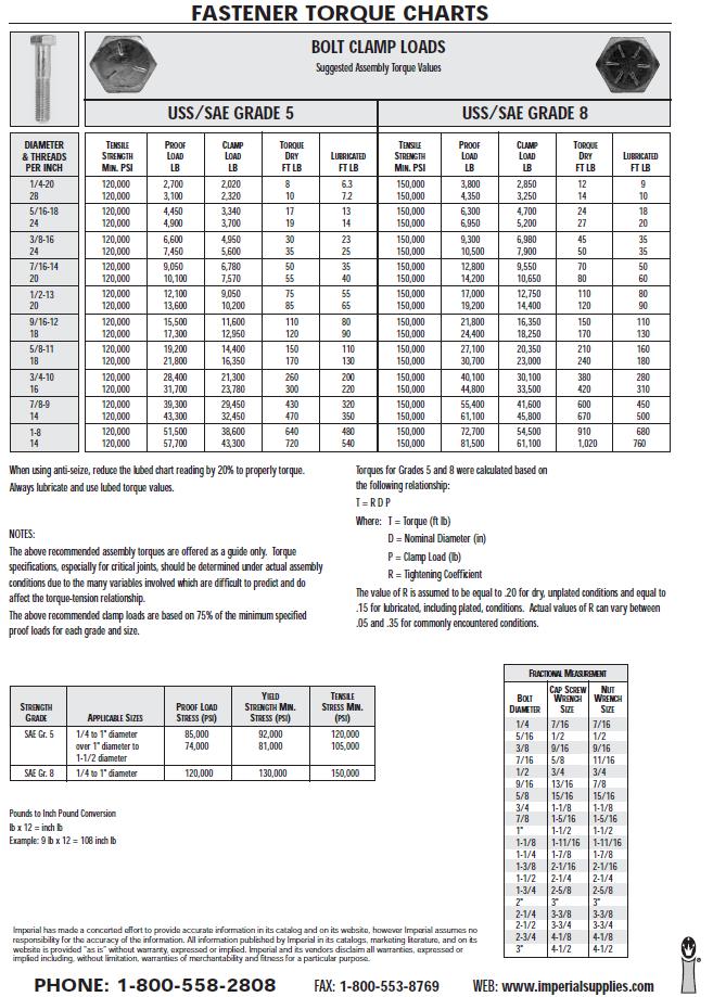
5 5 2. Body Assembly NOTE: Refer to component list at end for ID Numbers (in brackets). 1. Place the blade subassembly upright on a stable level surface. Make sure the blade is blocked appropriately for stability. 2. Using 1-1/2" bolts (20653), and hex nuts (20654) attach the hitch subassembly (or trencher hitch subassembly) to the neck of the blade subassembly. Washers (20434) must be placed one on each side of the blade and hitch plates. Note: These bolts must be lubricated and torqued to 1800 ft-lb. Figure 1 - Blade to hitch Attachment 3. Lift the main frame subassembly keeping it level and line it up with the mounting holes on the blade subassembly.
, blade pin collars (23342), 1/2 x 4 bolts (15574), and 1/2 nylon lock nuts (10241), attach the main frame to the blade.")
6 6 Figure 2 - Main frame to blade alignment 4. Using the blade pins (23338), blade pin collars (23342), 1/2 x 4 bolts (15574), and 1/2 nylon lock nuts (10241), attach the main frame to the blade. Figure 3 - Main frame attachment 5. Place blocks under main frame in order to maintain its horizontal position.
7 7 6. Attach the axle sub assembly to the main frame. Slide the axle into the main frame from the rear of the machine. Place the axle collar weldment onto the axle after sliding through the main frame. Then secure the axle in place with four 3/4 x 2 bolts (21243) and four 3/4 nylon lock nuts (10007). Figure 4 - Axle alignment 7. Assemble the hub and spindle. a) Insert rear bearing (3) into the hub housing. Install the seal (6) (with rubber lip to the outside (as shown). Lightly tap into place with a rubber mallet. b) Pack bearings full of grease (Mobil UNIREX EP2 GC-LB). Run grease around the inside of the hub with a spatula to fill the opening. c) Insert the spindle (2) as shown, with the shoulder up against the rear bearing. d) Insert front bearing (4), washer (9), and castle nut (8). e) Rotate the spindle a few times, then repack with grease. NOTE: Tighten after installed on machine. f) Tighten the castle nut until the bearings are tight, then back off one notch. Fix in place using the cotter pin (10). g) Install the dust cap (5), and gasket (7), using four 5/16" x 3/4" bolts (11).
8 8 Figure 5 - Hub and spindle assembly 8. Fasten the rim ( ) - ( ) to the hub using spherical washers (21151) and wheel nuts (20783). The flat side of the spherical washers should contact the surface of the rim with the spherical side against the wheel nuts. NOTE: Valve stem on outside. Figure 6 - Hub and wheel assembly Tire Size , 12 ply 28L-26, 16 ply Rim Size DW20A-26 DW25B-26 Tire Pressure 16 psi 24 psi Wheel Nut Torque 325 ft-lb 325 ft-lb
9 9 9. Install the spindle to the axle using 3/4" x 6-1/2" (20787) bolts and nylon lock nuts (10007). Figure 7 - Spindle to axle assembly 10. Bolt the hitch (Cat. 4 or Cat. 4.5) to the front of the hitch subassembly using two 1" x 7-1/2" Gr.8 NF bolts (21103), and Stover lock nuts (21104). Set to the desired height (usually centered) with the lettering on the top side. The Cat.4 hitch has two available pin sizes. Install the desired size by removing the snap ring from the bushing. Draw Pin Size (inches) Hitch Required Part NO 1.50 Flanged Bushing Category 4 * with 2" bushing installed, 2 Hole Pattern Category 4 * with 2" bushing installed, 3 Hole Pattern Category 5, 2 Hole Pattern Figure 8 - Hitch installation

10 3. Hydraulics Assembly NOTE: Hydraulic cylinders must be attached at the top first then pulled down into position. A hydraulic schematic will be attached at the back of the Hydraulics Assembly Section. 1. Align the 5 x 24 cylinders (20431) with the cylinder attachment holes on the blade subassembly (ports down, ram end to bottom). Insert 1-1/4 x 3-3/8 cylinder pins (20688) into the blade holes. Secure the cylinder pins with 3/16 x 2 cotter pins (11670). Figure 9-5x24" cylinder attachment (top) 2. Pull the piston ends of the cylinders down and align the clevis holes with the cylinder attachment holes on the Pulldozer's main frame. Align the lift cylinder locks (20630) with the clevis holes. Insert cylinder pins (20665) through the holes on the lift cylinder lock, cylinder clevis and main frame. Secure with 1 ¼ washers (16650) on outside of lift cylinder lock and 3/16 x 2 cotter pins (11670).
, align the clevis on the barrel end of the cylinder with the cylinder attachment hole on the top bar of the main frame (ports down).")
11 11 Figure 10-5x24" cylinder attachment (bottom) 3. Using a 3 x 20 hydraulic cylinder (20488), align the clevis on the barrel end of the cylinder with the cylinder attachment hole on the top bar of the main frame (ports down). Insert cylinder pin (10339) 1 x 2-7/8 through the clevis and cylinder attachment hole. Secure with 3/16 x 2 cotter pins (11670). Figure 11-3x20" cylinder attachment (top)
12 12 4. Pull the piston end of the cylinder down and align the clevis with the cylinder attachment hole on the Pulldozer's axle. Align the tilt cylinder lock (21228) with the clevis hole. Insert cylinder pin (20788) through the holes on the tilt cylinder lock, clevis, and axle. Secure with 1 flat washers (14472) on outside of cylinder locks and 3/16 x 2 cotter pins (11670). Figure 12-3x20" cylinder attachment (bottom) 5. Install cylinder port fittings: - Install 12MB-8MJ90 fittings to each port of the 5" cylinders - Install 6MB-6MJ90 fittings to each port of the 3" cylinders - Leave the fittings loose until the hoses are connected, then rotate to the position that works best for hose routing.
13 13 Figure 13 - Cylinder port fittings 6. Run hoses from cylinders to back of blade (see schematic at end of section). Install fittings on bulkheads as shown. NOTE: Do not install rear bulkhead plate until electrical wiring is complete Figure 14 - Rear bulkhead fittings
14 14 7. Attach hoses to frame and blade using hose clamps : - 1/2" clamps and cable clamps on blade (x3), along bottom of main frame (x2), and on the upright of the main frame (x1). - 1/2" clamps without cable clamps on front of main frame upper cross member (x1) - 3/8" clamps without cable clamps of rear of main frame upper cross member (x2) : - 1/2" clamps with cable clamps on blade (x3), along bottom of main frame (x2), and on the upright of the main frame (x1) Clamp assembly Tilt cylinders (2400 shown, 1800 has no clamps Lift cylinders Main frame Figure 15 - Rear hose routing - Tie any loose hoses together using zip ties or hose straps to complete the rear hose routing.

 Insert hoses into the hole in the")

15 15 8. Run tractor hoses: a) Attach hose fittings as shown below, tighten hoses to the bulkhead fitting, leave nut loose between the bulkhead and the hitch hose. Figure 16 - Hitch to tractor hose connection ITEM NO. DESCRIPTION QTY. 1 8MJBH-8MJ Bulkhead Nut 4 3 Tractor Hose 4 4 Hitch Hose 4 b) Insert hoses into the hole in the hitch, and run back to the rear bulkhead plate. Connect to the fittings, then bolt the rear bulkhead plate on. NOTE: Keep track of which hose is which. Figure 17 - Front bulkhead assembly c) Loosely place the hoses in the grooves in (1). The plate should go between the bulkhead flange and the nut.

 Bolt the assembled bulkhead plate to the hitch using 3/8\" x 1\" (13806) bolts.")
 Install pioneer fittings (17379) to the end of each hose and mark with heat shrink.")
16 16 d) Place under in between the bulkhead flange and the nut so the bulkhead fitting is clamped between the semi-circles on the two plates. Slide the lower plate up until flush with the other plate. Tighten the nuts on the lower side. e) Bolt the assembled bulkhead plate to the hitch using 3/8" x 1" (13806) bolts. NOTE: Do not do this step until the electrical wiring is run. f) Install pioneer fittings (17379) to the end of each hose and mark with heat shrink. - Green 1" runs to right tilt cylinder base/left tilt cylinder ram - Green 2" runs to right tilt cylinder ram/left tilt cylinder base - Red 1" runs to lift cylinder bases - Red 2" runs to lift cylinder rams
17 17 9. Bolt the spring hose holder (17967) to the front of the hitch as shown, using a 5/8" flat washer (13975) and nylon lock nut (10364). Loop hoses around to front of hitch and place in hose bracket. 10. Install a Velcro hose strap (17962) to the hoses where it splits from 4 to 2 on the back of the blade.
18 18
19 19 4. Electrical Assembly 1. Run main electrical cable (4-wire) through the hitch (see wiring diagram at end of section). It will run alongside the hydraulic lines, through the front bulkhead cover (using a grommet: 21428). Leave enough wire at the back for ease of making connections. Both bulkhead covers can then be installed. 2. Install 7-pin junction box (13668) to back of blade. First, a hole needs to be drilled in the junction box (see drawing) and then insert a grommet (21439) into it.
 to the end of each wire, and connect them to the posts (see wiring diagram). Pull back any slack in the cable towards the front of the machine. 3.")
20 20 Run cable through the hole, and bolt the junction box to the back of the blade using a 1/4" x 1" bolt. Split the end of the cable and separate the four wires. Attach a blue ring connector (21455) to the end of each wire, and connect them to the posts (see wiring diagram). Pull back any slack in the cable towards the front of the machine. 3. Connect the 7-pin trailer plug (12177) to the front of the machine as per the wiring diagram. 4. Attach each flasher light assembly to the blade using a 3/4" x 4-1/2 bolt (21460) and nylon lock nut (10007). Install cable clamps along the top of the blade on each side, and attach using 3/8" x 1" bolts (13806) and serrated flange nuts (10271). Figure 18 - Flasher light assembly
 to the bottom of the right tail light bracket.")
21 21 Install 2 grommets (21439) into each arm as shown. 5. Route the flasher electrical lines to the box and wire them in as per schematic. Figure 17: Flasher electrical lines route 6. Route the tail lights electrical line and wire it in to the box as per schematic. Install a grommet (21439) to the bottom of the right tail light bracket. The wire runs alongside the hydraulic lines on the main frame. Run a second wire between the tail lights through the main frame top tube. Install cap on junction box.
22 22 7. Install and wire all 6 lights (2 red , 4 amber ). A 3 wire, 90 degree pigtail (21422) should be plugged into the back of each light. A rubber grommet (21421) must also be placed around each light. Wire each pigtail to the cables as per the schematic. Solder and apply heat shrink to each joint to ensure a good connection. Shove each light into the holes until the grommet is properly seated. It should be a tight fit. Figure 19 - Amber light locations Figure 20 - Red light locations
23 23


24 24 5. Miscellaneous 1. There are 10 grease zerks installed on the Pulldozer that require grease before operation. There are 3 located where the main frame attaches to the blade (on each side), 2 where the axle attaches to the main frame, and two on the articulating hitch. Make sure all joints have sufficient grease. Figure 21 - Blade pin grease zerks Figure 22 - Axle pivot grease zerks
 or three (2400) 6 cutting edges (20430) and two 4 cutting edges (20428) using the scraper blade bolts (1800 x 45 2400 x 57) (20448) and ¾ nuts (1800 x 45 2400 x 57) (20606).")
25 25 Figure 23 - Articulating hitch grease zerks (x2) 2. After hooking up the Pulldozer to the tractor. Lift the blade off the ground and lock it in place. Then attach two (1800) or three (2400) 6 cutting edges (20430) and two 4 cutting edges (20428) using the scraper blade bolts (1800 x x 57) (20448) and ¾ nuts (1800 x x 57) (20606). Attach the 4 sections to the wings first, then the 6 sections to the center. Figure 24-4 Foot scraper blade attachment
 and nylon lock nuts (10241) as shown.")
26 26 Figure 25-6 Foot scraper blade attachment 3. Install the angle indicator arm. For both the 1800 and 2400, a different needle is required. It bolts to the axle collar using two 1/2" x 1-1/4" bolts (10240) and nylon lock nuts (10241) as shown. Angle Indicator Arm Figure 26 - Angle indicator install For the 2400 only, install the angle indicator readout bracket with the sticker facing the front, using two 3/8" x 1" (13806) bolts and the tapped holes in the top of the rear main frame tube.
27 27 Figure 27 - Angle indicator install - 24ft only For the 1800 only, install the sticker to the center of the top main frame tube. Set the angle indicator by leveling the blade side-to-side, then centering the needle on the center of the decal.
28 28 6. Trencher Option NOTE: For machines with the optional trencher, the hitch section is replaced with a special hitch. All other steps remain the same. All following steps can be done at any time after the hitch is installed. 1. Place the trencher arm underneath of the hitch, then lift it up into place and insert the pin (22099). Lock the pin in place using two 3/4" x 5" bolts (10803) and Stover lock nuts (11823). Lastly, install two 1/4" self-tapping grease zerks (16364) into the holes in the pivot pipe. Fill with grease until pipe is full. Figure 28 - Trencher install
 and serrated flange nuts (10271). 3. Install the depth indicator arm (22137) to the tabs on the top of the hitch using a 1/2\" x 3-1/4\" bolt and nylon lock nut.")
29 29 2. Place the indicator sticker ( ft, ft) onto the depth indicator bracket (27200) with the arrow pointing up. Then install the bracket to the tabs on the top of the hitch using four 3/8" x 1" carriage bolts (15718) and serrated flange nuts (10271). 3. Install the depth indicator arm (22137) to the tabs on the top of the hitch using a 1/2" x 3-1/4" bolt and nylon lock nut. The arm should pivot freely. Figure 29 - Depth indicator assembly 4. Install the depth indicator linkage (23341) to the welded on bolt on the ditcher (bushing end) using a 1/2" flat washer (11668) and nylon lock nut (10241). Install the other (slotted) end to the indicator arm using a 1/2" x 4-1/2" bolt (15574) and two serrated flange nuts (10273) to clamp the linkage. Make sure that the arm can still pivot up and down freely. The position within the slot will be set later.
30 30 5. Install 5" x 24" hydraulic cylinders (20431) with the ram on the ditcher side and the ports down. Secure at both ends with an 1-1/4" cylinder pin (20688) and two 3/16" cotter pins (11670). 6. Install 12MB - 8MJ90 fittings to each cylinder port, facing inwards and towards the front of the machine. Install two 8MJBH - 8MJT bulkhead tee fittings to the plate as shown, with the "tee" side towards the cylinders.
31 31 7. Run the hydraulic hoses. Two 22" hoses run from the top bulkhead fitting to the base end of the cylinders, and two 48" hoses run from the bottom bulkhead fitting to the ram end of the cylinders. NOTE: The 90 degree ends connect to the bulkhead. Finally, two 98" hoses run to the hitch of the machine. Install pioneer ends (8FB) to each hose, and yellow heat shrink marker (as shown). 8. Connect a tractor and charge the hydraulics. With the blade and the trencher tip both touching the ground, set the depth indicator to read "0". Lift the trencher into transport position and insert the safety lock (22136) and the lock pin (12050). ASSEMBLY IS NOW COMPLETE
32 32
33 33
PULLDOZER TRANSFORMER
 PULLDOZER TRANSFORMER 1870 1870XL Operator, Assembly & Parts Manual Last Updated: December 6, 2018 Bridgeview Manufacturing Inc. P.O. Box 4 Gerald, Saskatchewan, Canada S0A 1B0 Phone: 1-306-745-2711 Fax:
PULLDOZER TRANSFORMER
 PULLDOZER TRANSFORMER 1850 1850XL Operator, Assembly & Parts Manual Last Updated: August 28, 2018 Bridgeview Manufacturing Inc. P.O. Box 4 Gerald, Saskatchewan, Canada S0A 1B0 Phone: 1-306-745-2711 Fax:
PULLDOZER TRANSFORMER
 PULLDOZER TRANSFORMER 1850 1850XL Operator, Assembly & Parts Manual Last Updated: July 20, 2017 Bridgeview Manufacturing Inc. P.O. Box 4 Gerald, Saskatchewan, Canada S0A 1B0 Phone: 1-306-745-2711 Fax:
PULLDOZER TRANSFORMER
 PULLDOZER TRANSFORMER 2450 2450XL Operator, Assembly & Parts Manual Last Updated: July 19, 2018 Bridgeview Manufacturing Inc. P.O. Box 4 Gerald, Saskatchewan, Canada S0A 1B0 Phone: 1-306-745-2711 Fax:
VR482 Hay Rake OPERATOR & PARTS MANUAL. Last Updated: May 12, 2014
 VR482 Hay Rake OPERATOR & PARTS MANUAL Last Updated: May 12, 2014 Bridgeview Manufacturing Inc. P.O. Box 4 Gerald, SK S0A 1B0 (306) 745-2711 www.bridgeviewmanufacturing.com bmi@sasktel.net Your Authorized
BALE KING VR483. Hay Rake. Operator's & Parts Manual. Last Updated: April 27, Bridgeview Manufacturing Inc.
 BALE KING VR483 Hay Rake Operator's & Parts Manual Last Updated: April 27, 2015 P.O. Box 4 Gerald, Saskatchewan, Canada S0A 1B0 Phone: 1-306-745-2711 Fax: 1-306-745-3364 Email: bmi@sasktel.net www.bridgeviewmanufacturing.com
PARTS MANUAL BALE KING V-RAKE VR810 GREEN AND YELLOW ITEM NUMBERS
 PARTS MANUAL BALE KING V-RAKE VR810 GREEN AND YELLOW ITEM NUMBERS MANUFACTURED BY: BRIDGEVIEW MANUFACTURING INC. P.O. BOX 4 GERALD, SASK. CANADA S0A 1B0 PHONE: (306) 745-2711 FAX: (306) 745-3364 TABLE
PARTS MANUAL VR 1214 BALE KING V-RAKE GREEN AND YELLOW NUMBERS
 PARTS MANUAL VR 1214 BALE KING V-RAKE GREEN AND YELLOW NUMBERS MANUFACTURED BY: BRIDGEVIEW MANUFACTURING INC. P.O. BOX 4 GERALD, SASK. CANADA S0A 1B0 PHONE: (306) 745-2711 FAX: (306) 745-3364 TABLE OF
BALE KING VORTEX 3110 BALE KING GREEN & DEGELMAN BALE KING YELLOW MODELS
 PARTS MANUAL BALE KING VORTEX 3110 BALE KING GREEN & DEGELMAN BALE KING YELLOW MODELS MANUFACTURED BY: BRIDGEVIEW MANUFACTURING INC. P.O. BOX 4 GERALD, SASK. CANADA S0A 1B0 PHONE: (306) 745-2711 FAX: (306)
BALE KING VORTEX 3100 HD BALE KING GREEN & DEGELMAN BALE KING YELLOW MODELS
 PARTS MANUAL BALE KING VORTEX 3100 HD BALE KING GREEN & DEGELMAN BALE KING YELLOW MODELS MANUFACTURED BY: BRIDGEVIEW MANUFACTURING INC. P.O. BOX 4 GERALD, SASK. CANADA S0A 1B0 PHONE: (306) 745-2711 FAX:
MidCap Rotary Rake. Illustrated Parts Breakdown
 MidCap Rotary Rake Illustrated Parts Breakdown Page Page Page Page Page Page Page Page Page Page 0 Page Page Page Page Page Page Page Page Page Main Frame Transport Wheel Assembly Lift Arm Assembly Main
Drive End Bracket & Bearing. Drive End Bracket. Tandem Axle # #865733
 Drive End Bracket & Bearing #865089 1 06409700 1" Lock Collar 2 865733 Drive Bracket w/ Bearing 3 310037 End Drive Shaft Drive End Bracket #865733 1 03003100 Bearing 1" w/snap Ring 2 957795 Drive End Bracket
RITE WAY MFG. CO. LTD. P.O.
 CO. LTD. P.O. Box 328 Imperial, Saskatchewan Canada, S0G 2J0 Ph: (306) 963-280 Fax: (306) 963-2660 Web Site: www.ritewaymfg.com E-mail: info@ritewaymfg.com Table of Contents SPECIFICATIONS... WARNING...2
TT8101 Rotary Tedder
 TT0 Rotary Tedder Illustrated Parts Breakdown Page Front End Page Page Transport Axle Assembly Cylinder Linkage Page Guards Page Page Page Page Transport Lock Assembly Lift Frame Assembly Center Tunnel
KONGSKILDE 9200 DF Vertical Tillage - Assembly/Parts
 KONGSKILDE 9200 DF Vertical Tillage - Assembly/Parts Kongskilde 9200 *Model may not be exactly as shown. Kongskilde reserves the right to make changes to product designs and specifications without notice
HT46X Rotary Tedder. Illustrated Parts Breakdown. Center Section
 HTX Rotary Tedder Illustrated Parts Breakdown Page Page Page Page Page Page Page Page Page Page 0 Page Center Section Hydraulics Outer Wing Assembly Center Bolted Components Tine Rotor and Hardware Tilt
OWNER S MANUAL. PTO Generator Trailer ITEM # For use on 13000, 27500, and PTOG North Star Generators or Other PTO Generators up to 60kW.
 PTO Generator Trailer ITEM # 165959 For use on 13000, 27500, and 60000 PTOG North Star Generators or Other PTO Generators up to 60kW. M165959C PLACE MANUAL NAMEPLATE HERE OWNER S MANUAL 00641 Any Questions,
TT4100 Rotary Tedder
 TT0 Rotary Tedder Serial numbers 0 and higher Illustrated Parts Breakdown Page Page Tongue Assembly S/N - Tongue Assembly S/N to Page Page Page Page Page Tongue Assembly S/N to Tongue Assembly S/N + Main
TT4101 Rotary Tedder
 TT Rotary Tedder 0//0 Illustrated Parts Breakdown Page Page Page Page Page Page Page Page Page Page Page Tongue Assembly S/N S/N - Tongue Assembly S/N + Main Frame S/N - Main Frame S/N to Main Frame S/N
PARTS MANUAL. HD4SR and 12SR Auto Align Bale Skoop to 2017 K
 PARTS MANUAL 1998 to 2017 HD4SR and 12SR Auto Align Bale Skoop K34991-04 Table of Contents Section 1: Parts Breakdown...1-1 Bale Skoop Final Assembly... 1-2 Loader Assembly... 1-4 12SR - Grab Hook Assembly
530B ECOLO-TIGER MULCH CHISEL WARNING AND TAILIGHT KIT ECOLO-TIGER 530B
 04-01 WARNING AND TAILIGHT KIT ECOLO-TIGER 530B 04-01 WARNING AND TAILIGHT KIT ECOLO-TIGER 530B 2 27602311 1 HARNESS, WIRE, Front 3 27602221 1 HARNESS, WIRE, Rear (530B) 4 27602202 2 LIGHT ASSY., Red 5
BALE KING GT40 Grain Feeder Operator's & Parts Manual Last Update: November 20, 2014 Bridgeview Manufacturing Inc - 1 -
 BALE KING GT40 Grain Feeder Operator's & Parts Manual Last Update: November 20, 2014 Bridgeview Manufacturing Inc - 1 - Your Authorized Dealer: Your Serial Number: The Serial Number is located on the tank.
Parts Book 612N, 812N, 642N, 842N, 862N 714NT, 814NT, 742NT, 842NT, 862NT
 Parts Book 612N, 812N, 642N, 842N, 862N 714NT, 814NT, 742NT, 842NT, 862NT Wishek Mfg. LLC 112 South 2nd Street PO Box 185 Wishek, ND 58495 (701) 452-2449 www.wishekmfg.com WARRANTY/ PARTS RETURN POLICY
Fold Hydraulics Item Qty Part No. Description
 Fold Hydraulics 1 2 465385 Quick Coupler 3/4"-16 FOR 2 2 469882 Hose ½" x 468" (3/4 FJSw x 3/4 MOR) 3 2 469833 Hose ½" x 87" (3/4 FJSw) 4 4 465310 Adapter 90 (3/4 MOR x 3/4 JICM) 5 2 469866 Hose ½" x 230"
TT6101 Rotary Tedder
 TT0 Rotary Tedder 0/0/0 Illustrated Parts Breakdown Page Chassis Assembly Page Page Transport Axle Assembly S/N - Transport Axle Assembly S/N + Page Page Page Page Page Transport Lock Assembly Lift Frame
TEREX Woodsman 730 BRUSH CHIPPER
 Woodsman 730 BRUSH CHIPPER Parts Manual Customer Dealer S/N Frame # Date Woodsman 150 Commerce Drive, Farwell MI 486 Phone: (800) 953-553 Fax: (989) 588-487 Flipper Discharge Chute Hand Crank Belt Shield
RW 1200 ROCK WINDROWER. Table of Contents
 RITE WAY MFG. CO. LTD. P.O. Box 328 Imperial, Saskatchewan Canada, S0G 2J0 Ph: (306) 963-2180 Fax: (306) 963-2660 Web Site: www.ritewaymfg.com E-mail: info@ritewaymfg.com RW 1200 ROCK WINDROWER Table of
ALL PLANT & MIN TILL DRILL
 4000 SERIES ALL PLANT & MIN TILL DRILL OWNER S MANUAL ADDENDUM OPERATION MAINTENANCE REPAIR PARTS #608869 (03-08) 2 Table of Contents Precision Planting Metering System 5-9 Precision Planting Introduction
Parts Manual for PRO GEAR EXPRESS MID-SIZE WALK BEHIND MOWERS SERIES 0 & 1 POWER UNIT MODEL SPE1250KW SPE140KW SPE150KH SPE151KW SPEL150KH
 Parts Manual for PRO GEAR EXPRESS MID-SIZE WALK BEHIND MOWERS SERIES 0 & 1 POWER UNIT MODEL SPE10KW SPE0KW SPE10KH SPE11KW SPEL10KH MOWER UNIT MODEL SPE30 SPE480 SPE31 SPE481 IT IS POLICY OF SNAPPER TO
ASSEMBLY MANUAL. 45-Foot Air Double Disc Drill. Amity Technology, LLC th Avenue North Fargo, ND (701)
") ASSEMBLY MANUAL 45-Foot Air Double Disc Drill Amity Technology, LLC 2800 7th Avenue North Fargo, ND 58102 (701) 232-4199 www.amitytech.com TABLE OF CONTENTS Main Frame 1 Wing Lock Towers 3 Wing Frames
ASSEMBLY MANUAL 45-Foot Air Double Disc Drill Amity Technology, LLC 2800 7th Avenue North Fargo, ND 58102 (701) 232-4199 www.amitytech.com TABLE OF CONTENTS Main Frame 1 Wing Lock Towers 3 Wing Frames
BUSH HOG LAND MAINTENANCE REPAIR PARTS MANUAL MODEL: TD-1100 SECTION: 66
 BUSH HOG LAND MAINTENANCE REPAIR S MANUAL MODEL: TD-00 SECTION: 0 Griffin Ave. Selma, AL 0 () - () -00 Parts Ordering -00-0- Fax -00-- www.bushhog.com BUSH HOG/ LAND MAINTENANCE REPAIR S MANUAL JUNE, 00
PRO HYDRO WALK BEHIND MOWERS MID-SIZE SERIES 3
 Parts Manual for MID-SIZE SERIES 3 POWER UNIT MODELS SPLH153KW SPLH173KW MOWER MODELS SPA361 SPA481 SPA521 SPA611 McDonough, GA, 30253 U.S.A. COPYRIGHT 2005 SNAPPER PRODUCTS, INC. ALL RIGHTS RESERVED.
250P Manure Spreader
 0P Manure Spreader Illustrated Parts Breakdown Page - Page Page Page Page Page Page Page Page Page Page Page Page Page Page - Page Page Page 0 Complete Front End PTO/Jack/Hitch Assembly Front Pulley Assembly
KONGSKILDE 8200 DF Field Cultivator - Assembly/Parts
 KONGSKILDE 8200 DF Field Cultivator - Assembly/Parts Kongskilde 8200 Models 768236901 8236 Field Cultivator (36.5') 768238901 8238 Field Cultivator (38.5') 768240901 8240 Field Cultivator (40.5') 768242901
601 N. Broadway Salina, KS Veris MSP3 EC/pH/OM Parts Manual
 601 N. Broadway Salina, KS 67401 Veris MSP3 EC/pH/OM Parts Manual MSP3 Sub-Assemblies 2 Table of Contents MSP 3150 Base Unit... 4, 5 Coulter Assembly... 6, 7 ph Sampler... 8-10 Electrode Holder... 11,
Highline Manufacturing TopGun 1999 Page 1 A. TABLE OF CONTENTS... 1
 Highline Manufacturing TopGun 1999 Page 1 A. Table of Contents A. TABLE OF CONTENTS... 1 B. ASSEMBLY & INSTALLATIONS... 3 1. FLAIL DRUM ASSEMBLY... 3 2. FLAIL DRUM INSTALLATION... 4 3. FEED ROLLER ASSEMBLY...
LAND MAINTENANCE REPAIR PARTS MANUAL BUSH HOG MODEL: 307 SECTION: 16
 BUSH HOG LAND MAINTENANCE REPAIR S MANUAL MODEL: 0 SECTION: P.O. Box 0 Selma, AL 0-0 () - () -00 Parts Ordering -00-0- Fax -00-- www.bushhog.com BUSH HOG / LAND MAINTENANCE REPAIR S MANUAL SEPTEMBER, 0
Mulching and Finishing Mowers MP and FP
 Mulching and Finishing Mowers MP and FP Parts Manual Locke Turf 0 Highway E, Opp, Alabama, () -00 Transport Wheel, Tire & Spindle MP and FP ALPHABETICAL INDEX CONTENTS PAGE 00 Hydraulic Cylinder (Rear)
Champion Series Zero-Turn Riders & Mower Decks
 Parts Manual Champion Series Zero-Turn Riders & Mower Decks HP Tractors Mfg. No. Description Champion, HP Zero-Turn Rider Champion, HP Zero-Turn Rider (CE) 0HP Tractors Mfg. No. Description Champion, 0HP
Parts Manual SERIES CVT Lawn Tractor. Model LT1040 CUB CADET LLC, P.O. BOX CLEVELAND, OHIO PRINTED IN U.S.A.
 Parts Manual CVT Lawn Tractor SERIES 000 Model LT00 PRINTED IN U.S.A. CUB CADET LLC, P.O. BOX CLEVELAND, OHIO -00 FORM -00C.fm (//00) SERIES 000 CVT LAWN TRACTORS TABLE OF CONTENTS DESCRIPTION PAGE Axle,
HOW TO ORDER PARTS: Unless this is done, we cannot provide prompt service or assure shipment of the correct parts.
 How to Order Parts HOW TO ORDER PARTS: IMPORTANT Parts must be ordered through your local authorized ASHLAND dealer. Be sure to state MODEL and SERIAL NUMBER of your machine, PART NUMBER, DESCRIPTION and
MODEL 45 SCRAPER INDEX
 MODEL 45 SCRAPER HOW TO ORDER PARTS: Be sure to state MODEL and SERIAL NO. of machine, PARTS NO., DESCRIPTION, and QUANTITY wanted. Unless this is done, we cannot provide prompt service or assure shipment
Trailer Parts. Brake Components. Axle Components. Suspensions. Lights & Electrical. Wheels & Tires. Loading Ramps. Couplers & Safety Chains
 Trailer Parts Brake Components Axle Components Suspensions Lights & Electrical Wheels & Tires Loading Ramps Couplers & Safety Chains Trailer Jacks Fenders Dump Trailer Parts Tilt SST Parts Decal Kits Brake
Model 1550 Series In-Row Ripper Parts Manual
 Model 1550 Series In-Row Ripper Parts Manual LANDOLL CORPORATION 1900 North Street Marysville, Kansas 66508 (785) 562-5381 800-428-5655 ~ WWW.LANDOLL.COM F-299-0111 01/2011 Table of Contents 1 Instructions
BALE KING 5100/5100TR
 BALE KING 5100/5100TR Bale Processor Operator's & Parts Manual Last Updated: August 11, 2015 P.O. Box 4 Gerald, Saskatchewan, Canada S0A 1B0 Phone: 1-306-745-2711 Fax: 1-306-745-3364 Email: bmi@sasktel.net
By: Bale King Bale processor OPERATOR & PARTS MANUAL (NORTH-AMERICA)
") By: Bale King 6100 Bale processor OPERATOR & PARTS MANUAL WWW.BRIDGEVIEWMANUFACTURING.COM (NORTH-AMERICA) BRIDGEVIEW MANUFACTURING INC P.O BOX 4, HWY 22 GERALD, SASK. S0A 1B0 CANADA Ph: 306-745-2711 Fax:
By: Bale King 6100 Bale processor OPERATOR & PARTS MANUAL WWW.BRIDGEVIEWMANUFACTURING.COM (NORTH-AMERICA) BRIDGEVIEW MANUFACTURING INC P.O BOX 4, HWY 22 GERALD, SASK. S0A 1B0 CANADA Ph: 306-745-2711 Fax:
PARTSBOOK. This part of the manual contains part numbers and illustrations based on the latest information available at the time of print.
 2 PARTSBOOK This part of the manual contains part numbers and illustrations based on the latest information available at the time of print. Hall Manufacturing, Inc. reserves the right to make changes at
Lime Spreader. Model SL6. Illustrated Parts Breakdown. Front Hydraulics Rear Hydraulics Manifold Components. Spinner Assembly
 Lime Spreader Model SL Illustrated Parts Breakdown Page Page Page Page Page Page Page Page Page Page 0 Front End Front Hydraulics Rear Hydraulics Manifold Components Floor & Apron Axle Assembly Apron Drive
PARTS MANUAL THIS PAGE INTENTIONALLY LEFT BLANK. Ag-Bag International, Ltd. G7000 June Appendix A
 The parts manual is organized into groups, it is designed to make the locating of parts easier. The exploded drawings also show assembly paths. All parts listed are available from your authorized Ag-Bag
RITE WAY MFG. CO. LTD.
 P. O. Box 328 Imperial, Saskatchewan Canada, S0G 2J0 PH: (306) 963-2180 Web Site: www.ritewaymfg.com E-mail: info@ritewaymfg.com 33', 45', 55', 68' & 78' Solid Draft Arm Table of Contents INTRODUCTION...
GRAIN DECK BELT CONVEYOR PARTS LIST SERIAL NOS
 GRAIN DECK BELT CONVEYOR PARTS LIST SERIAL NOS. 112000-115499 1 DISCHARGE ASSEMBLY - GRAIN BELT DRIVE OVER CONVEYOR SERIAL NOS. 112000-115499 2 REF # PART NO. DESCRIPTION QTY 1 C200760 Discharge Weldment
REAR ENGINE RIDER 42 MOWER SERIES 22
 Parts Manual for REAR ENGINE RIDER MOWER SERIES MODELS 1BVE CONTENTS DESCRIPTION PAGE(S) DESCRIPTION PAGE(S) WHEELS- TIRES... - FRONT END, STEERING.... - MAIN CASE... - DIFFERENTIAL, R. H. FENDER... 8-9
Parts Manual PZ Please read the operator manual carefully and make sure you understand the instructions before using the machine.
 Parts Manual PZ 60 967 045601-00 Please read the operator manual carefully and make sure you understand the instructions before using the machine. When you need spare parts or support in service questions,
BALE KING 5200/5200TR
 BALE KING 5200/5200TR Bale Processor Operator's & Parts Manual Last Updated: February 2018 P.O. Box 4 Gerald, Saskatchewan, Canada S0A 1B0 Phone: 1-306-745-2711 Fax: 1-306-745-3364 Email: bmi@sasktel.net
RITE WAY MFG. CO. LTD. P.O. Box 328 Imperial, Saskatchewan Canada, S0G 2J0 Ph: (306) Fax: (306) Web Site:
 Fax: (306) Web Site:") CO. LTD. P.O. Box 328 Imperial, Saskatchewan Canada, S0G 2J0 Ph: (306) 963-2180 Fax: (306) 963-2660 Web Site: www.ritewaymfg.com E-mail: info@ritewaymfg.com 28, 40, 50, 62 & 73 Table of Contents INTRODUCTION...
CO. LTD. P.O. Box 328 Imperial, Saskatchewan Canada, S0G 2J0 Ph: (306) 963-2180 Fax: (306) 963-2660 Web Site: www.ritewaymfg.com E-mail: info@ritewaymfg.com 28, 40, 50, 62 & 73 Table of Contents INTRODUCTION...
WP865 Wood Processor Parts Manual
 EMB Manufacturing Inc. 4144 Boomer Line St. Clements, On N0B 2M0 Canada Ph: (519) 699-9283 Fax: (519) 699-4146 www.wallensteinequipment.com WP865 Wood Processor Parts Manual S/N 2E9US1115FS660079 2E9US1115FS660139
3. FRAME 1. SAFETY 2. PREPARATION 4. TRANSMISSION 5. DRIVE 6. ROW UNIT 7. OPTIONAL EQUIPMENT
 TABLE OF CONTENTS 1. SAFETY 2. PREPARATION 3. FRAME 4. TRANSMISSION 5. DRIVE 6. ROW UNIT 7. OPTIONAL EQUIPMENT FRAME 7" x 7" Stacker Bar STACKER BAR The Stacker Bar includes a heavy 3/8 wall tubing, 14
PIÈCES DÉTACHÉES. Chasse-neige. Révision 10/
 PIÈCES DÉTACHÉES Chasse-neige 555 860 Révision 10/2004 Y v a n B é a l - 2 1, a v. d e l A g r i c u l t u r e - B. P. 1 6 Z. I. d u B r é z e t - 6 3 0 1 4 C l e r m o n t - F e r r a n d C e d e x 2
Lime Spreader. Model SL6. Illustrated Parts Breakdown. Front Hydraulics Rear Hydraulics Manifold Components. Spinner Assembly
 Lime Spreader Model SL Illustrated Parts Breakdown Page Page Page Page Page Page Page Page Page Page 0 Front End Front Hydraulics Rear Hydraulics Manifold Components Floor & Apron Axle Assembly Apron Drive
TWIN ROTARY RAKE PARTS BOOK MODEL
 TWIN ROTARY RAKE PARTS BOOK MODEL 2650 17.01135 This parts book is furnished for your convenience only. All parts must be purchased through an authorized dealer. Call us for a dealer near you. Issue Date:
H.I.T Truck Tire Changer. Parts Identification
 H.I.T. 6000 Truck Tire Changer READ these instructions before placing unit in service KEEP these and other materials delivered with the unit in a binder near the machine for ease of reference by supervisors
J Parts catalog
 J-00 English version EDITION - 0/007 CODE - 979 Parts catalog MÁQUINAS AGRÍCOLAS JACTO S.A. Rua Dr. Luiz Miranda, 50 750-000 - Pompéia - SP - Brasil Tel.: +55 05-00 - Fax: +55 5 0 E-mail: export@jacto.com.br
Parts Manual for LAWN TRACTORS MANUAL CLUTCH HYDRO DRIVE SERIES F MODELS LT145H33FBV LT145H38FBV ELT145H33FBV
 Parts Manual for LAWN TRACTORS MANUAL CLUTCH HYDRO DRIVE SERIES F MODELS LT145H33FBV LT145H38FBV ELT145H33FBV IT IS THE POLICY OF SNAPPER TO IMPROVE ITS PRODUCTS WHENEVER IT IS POSSIBLE AND PRACTICAL TO
UST TB-10. Complete Trailer... Pg.1. Axles, Winches, Bunks, and Fenders... Pg.3
 UST-5500-78-TB-10 Complete Trailer... Pg.1 Axles, Winches, Bunks, and Fenders... Pg.3 TANDEM AXLE TRAILERS 31 32 36 42 34 35 38 37 10 24 39 17 40 2 7 8 9 18 41 16 1 23 4 5 13 14 15 20 11 21 6 23 14 22
18. REAR WHEEL/SUSPENSION
 18. REAR WHEEL/SUSPENSION SYSTEM COMPONENTS 182 REAR AXLE/BEARING HOLDER 187 SERVICE INFORMATION 183 REAR SHOCK ABSORBER 1816 TROUBLESHOOTING 186 SHOCK LINKAGE 1818 REAR WHEEL 187 SWINGARM 1820 181 SYSTEM
RZT TWIN STICK HYDRO DRIVE 250 Z 44" & 50" SERIES 0
 Parts Manual for RZT TWIN STICK HYDRO DRIVE 250 Z 44" & 50" SERIES 0 MODEL ERZT185440BVE RZT22500BVE2 McDonough, GA, 30253 U.S.A. COPYRIGHT 2006 SNAPPER PRODUCTS, INC. ALL RIGHTS RESERVED. Revision 1,
Trailer Parts. Brake Components. Axle Components. Suspensions. Lights & Electrical. Wheels & Tires. Loading Ramps. Couplers & Safety Chains
 Trailer Parts Brake Components Axle Components Suspensions Lights & Electrical Wheels & Tires Loading Ramps Couplers & Safety Chains Trailer Jacks Fenders Dump Trailer Parts Tilt SST Parts Decal Kits Brake
Reproduction. Not for. Signature Pro Dual Stage Snowthrowers. Parts Manual. Attachment
 Parts Manual Attachment Signature Pro Dual Stage Snowthrowers Mfg. No. Description 1695656 P1628EX, 15.5TP 28" Two-Stage Snowthrower (CE/Export) 1695657 P1732EX, 16.5GT 32" Snowthrower (CE/Export) 1695658
PULLDOZER Scraper Pan Operator s & Assembly Manual. Last Updated: July 27, 2017
 1220 Scraper Pan Operator s & Assembly Manual Last Updated: July 27, 2017 Bridgeview Manufacturing Inc. P.O. Box 4 Gerald, Saskatchewan, Canada S0A 1B0 Phone: 1-306-745-2711 Fax: 1-306-745-3364 Email:
GSN-8 Spreader. Illustrated Parts Breakdown. Page 1 Front End Assembly Page 2 Axle Assembly Page 3 Floor & Apron Page 4 Pump Assembly
 GSN- Spreader Illustrated Parts Breakdown Page Front End Assembly Page Axle Assembly Page Floor & Apron Page Pump Assembly Page Hydraulics Page Manifold Components Page Manifold Cover Page Gearbox Components
Land Cruiser FJ80 and FZJ80 Double Swingout Rear Bumper Installation Instructions PRELIMINARY
 Land Cruiser FJ80 and FZJ80 Double Swingout Rear Bumper Installation Instructions Fits 1991-1997 80 Series Land Cruiser / Lexus LX450 PRELIMINARY Thank you for purchasing a Rear Bumper for your Land Cruiser.
H.I.T Truck Tire Changer. Parts Identification
 H.I.T. 6000 Truck Tire Changer Parts Identification READ these instructions before placing unit in service KEEP these and other materials delivered with the unit in a binder near the machine for ease of
Parts Manual for PRO GEAR EXPRESS MID-SIZE WALK BEHIND MOWERS SERIES 0 & 1 POWER UNIT MODELS MOWER MODELS SPE140KW SPE151KW SPEL150KH
 Parts Manual for MID-SIZE WALK BEHIND MOWERS SERIES 0 & 1 POWER UNIT MODELS SPE1250KW SPE131KW SPE140KW SPE150KH SPE151KW SPEL150KH MOWER MODELS SPE360 SPE361 SPE481 McDonough, GA, 30253 U.S.A. COPYRIGHT
MODEL 328 (306) : 8190 JUMBO HEAVY HARROW
 : 8190 JUMBO HEAVY HARROW") P. O. Box 328 Imperial, Saskatchewan Canada, S0G 2J0 PH: (306) 963-2180 Web Site: www.ritewaymfg.com E-mail: info@ritewaymfg.com 90 Solid Draft Arm Table of Contents INTRODUCTION... 1 SPECIFICATIONS...
P. O. Box 328 Imperial, Saskatchewan Canada, S0G 2J0 PH: (306) 963-2180 Web Site: www.ritewaymfg.com E-mail: info@ritewaymfg.com 90 Solid Draft Arm Table of Contents INTRODUCTION... 1 SPECIFICATIONS...
Parts Manual. Models: ZCBI48180 MANUAL NO REV. IR (12/01/03)
") Parts Manual Models: ZCBI880 MANUAL NO. 0989 REV. IR (/0/0) INDEX MAIN FRAME ASSEMBLY... - CONSOLE ASSEMBLY... 8 CASTER ASSEMBLY... 9 MOTION CONTROL ASSEMBLY... 0- MOTION CONTROL LEVERS... - DECK LIFT
Parts Manual Models: ZCBI880 MANUAL NO. 0989 REV. IR (/0/0) INDEX MAIN FRAME ASSEMBLY... - CONSOLE ASSEMBLY... 8 CASTER ASSEMBLY... 9 MOTION CONTROL ASSEMBLY... 0- MOTION CONTROL LEVERS... - DECK LIFT
INSTRUCTION MANUAL ALL TERRAIN PALLET TRUCK HAND PALLET TRUCK
 INSTRUCTION MANUAL ALL TERRAIN PALLET TRUCK HAND PALLET TRUCK WARNING! 1. Read and understand instruction manual before using the pallet truck. 2. Do not place hands or feet under the pallet truck at any
EUROPEAN REAR ENGINE RIDER SERIES 20
 Parts Manual for EUROPEAN REAR ENGINE RIDER SERIES 20 MODEL E281320BE E331520KVE McDonough, GA, 30253 U.S.A. Briggs & Startton Yard Power Products Group Copyright 2006 Briggs & Startton Corporation Milwaukee,
Lime Spreader. Model SL10. Illustrated Parts Breakdown. Hydraulic System Hydraulic Manifold. Twin Speed Reducer
 Lime Spreader Model SL0 Illustrated Parts Breakdown Page Page Page Page Page Page Page Page Page Page 0 Front End Hydraulic System Hydraulic Manifold Switch Box Floor & Apron Axle Assembly Apron Drive
I-110 PARTS MANUAL Updated 3/21/01
 I-110 PARTS MANUAL Updated 3/21/01 Ashland Industries Inc. Hwy. 13 South P.O. Box 717 Ashland, WI. 54806 877-634-4622 Toll Free - phone 715-682-4622 phone 715-682-9717 fax www.ashlandind.com MODEL I-100,
13AU609H063 (1999) Page 1 of 25 Axle & Wheels Front And Steering Assembly
 Page 1 of 25 Axle & Wheels Front And Steering Assembly") 13AU609H063 (1999) Page 1 of 25 Axle & Wheels Front And Steering Assembly 13AU609H063 (1999) Page 2 of 25 Axle & Wheels Front And Steering Assembly 1 683-0304 1 S Frame 2 710-0604A 1 /P Self-tapping Screw,
13AU609H063 (1999) Page 1 of 25 Axle & Wheels Front And Steering Assembly 13AU609H063 (1999) Page 2 of 25 Axle & Wheels Front And Steering Assembly 1 683-0304 1 S Frame 2 710-0604A 1 /P Self-tapping Screw,
TRANSPORT AUGER TUBE / UNDERCARRIAGE / DRIVE COMPONENTS. INDEX Section L
 INDEX Section L TRANSPORT AUGER TUBE / UNDERCARRIAGE / DRIVE COMPONENTS TRANSPORT AUGER TUBE / UNDERCARRIAGE/ TF WHEEL MOVE L Description Page TF3, TF3, TF03, TF03 Basic Auger...L-3 TF, TF0 Basic Auger...L-
PARTS BOOK PARTS BOOK CATALOG
 PARTS BOOK PARTS BOOK CATALOG BOOM FLEXWING MOWER MOWERS HEADS ROTARY 15 CUT FLAIL DRAWBAR SAW HEAD MOUNT DITCHER DIAMOND MOWERS, LLC 350 E 60 th St. North Sioux Falls, SD 57104 FOR WARRANTY CALL DIAMOND
72K850ZP PARTS MANUAL
 7 2 K 8 5 0 Z P PARTS MANUAL 72 MID-CUT GAS ENGINE OPTION SECTION 72 MID-CUT DECK ASSEMBLY 72" Mid-Cut Deck Assembly # PART NO. QTY DESCRIPTION 1 582096 1 72" MC DECK WELDMENT 2 582098 1 72" DECK CHANNEL
KARAVAN T R A I L E R S
 C 0 MJH B 036 KMH 06--2 04-0-0 ADDED (4)2-0036. REPLACED 8-0003 WITH 8-00049; -0002 WITH -00 - (2X); -00046 WITH -00330; -0004 WITH -0006; -00048 WITH -0006.X 0.00.XXXX 0.00 OF NOTES:.) WINCH SHOULD BE
KMW PARTS PRICE LIST 1860 LOADER 2014 PART # PART DISCRIPTION LIST PRICE
 PART # PART DISCRIPTION LIST PRICE 0595-3084 Decal Warning $5.28 0595-3001 Decal Warning $1.92 0595-3002 Decal Danger $2.28 0595-3003 Decal Warning $2.16 0595-3004 Decal Warning $2.04 0595-3088 Decal KMW
LAWN TRACTORS ELECTRIC CLUTCH HYDRO DRIVE SERIES "G"
 Parts Manual for LAWN TRACTORS ELECTRIC CLUTCH HYDRO DRIVE SERIES "G" MODEL LT160H42GBV LT160H42GBV2 LT180H48GBV2 WLT160H42GBV WLT180H48GBV2 McDonough, GA, 30253 U.S.A. COPYRIGHT 2006 SNAPPER PRODUCTS,
Reproduction. Not for HYDRO DRIVE 46" 22 HP ZTR 360Z SERIES. Parts Manual for ZT2246
 Parts Manual for HYDRO DRIVE 46" 22 HP ZTR 360Z SERIES Model No. Description 2691316-00 ZT2246 Briggs & Stratton Yard Power Products Group 3515 N. 124 Street / PO Box 702 Wauwatosa, WI 53222 U.S.A. 800-935-2967
LAWN TRACTORS MANUAL CLUTCH HYDRO DRIVE SERIES "G"
 Parts Manual for LAWN TRACTORS MANUAL CLUTCH HYDRO DRIVE SERIES "G" MODEL ELT145H33GBV LT145H33GBV LT145H38GBV LT150H38GKV WLT145H38GKV McDonough, GA, 30253 U.S.A. COPYRIGHT 2006 SNAPPER PRODUCTS, INC.
Serial #
 Serial #155000-155999 January 2015 Blank page GENERATION 2 PARTS MANUAL DESCRIPTION PAGE TABLE OF CONTENTS 1 MAINFRAME ASSEMBLY 2-3 EXTENSION ARM ASSEMBLY 4-5 BASKET HANGER, FRAME, & LIFT ASSEMBLY 6-7
Parts Manual RAM 44 / RAM 50 / RAM MAG 44 / RAM MAG 50 / RAM MAG 50 / RAM MAG 44 / RAM
 Parts Manual RAM 44 / 968999551 RAM 50 / 96899955 RAM MAG 44 / 968999559 RAM MAG 50 / 968999561 RAM MAG 50 / 96899956 RAM MAG 44 / 968999650 RAM MAG 50 / 968999651 Please read the operator s manual carefully
Reproduction. Not for HYDRO DRIVE 46" 22 HP ZTR 360Z SERIES. Parts Manual for ZT2246
 Parts Manual for HYDRO DRIVE 46" 22 HP ZTR 360Z SERIES Model No. Description 2691316-00 ZT2246 Briggs & Stratton Yard Power Products Group 3515 N. 124 Street / PO Box 702 Wauwatosa, WI 53222 U.S.A. 800-935-2967
REAR ENGINE RIDER EUROPEAN SERIES 22
 Parts Manual for REAR ENGINE RIDER EUROPEAN SERIES 22 MODELS E2822BE E2822BE E1522KVE CONTENTS DESCRIPTION PAGE(S) DESCRIPTION PAGE(S) WHEELS, TIRES...2, DRIVE DISC ASSEMBLY... 22 FRONT END, STEERING...4,
NORTHSTAR TRAILERS. Assembly Guide for SPORTSTAR II Trailer
 NORTHSTAR TRAILERS Assembly Guide for SPORTSTAR II Trailer Congratulations! You are the proud owner of a NORTHSTAR trailer. Please follow the instructions and steps in this manual for proper assembly.
HANDLEBAR AND CONSOLE ASSEMBLY
 Section 6 Parts List HANDLEBAR AND CONSOLE ASSEMBLY 4 33 47 4 49 7 3 78 4 97 46 44 37 38 37 48 39 35 36 34 7 3 4 5 45 4 3 4 0 33 9 96 80 6 300 84 9 5 30 4 9 30 4 3 43 97 0 43 3 68 9 9 Models 753B, F753B
MODEL 25 SCRAPER INDEX
 MODEL 25 SCRAPER HOW TO ORDER PARTS Be sure to state MODEL and SERIAL NO. of machine, PARTS NO., DESCRIPTION, and QUANTITY wanted. Unless this is done, we cannot give you prompt service or send the correct
HYDRAULIC ASSEMBLY (TE) MODELS: ,
 MODELS: ,") 6 HYDRAULIC ASSEMBLY (TE) 6 6 0 6 MODELS: 6, 60 0 0 0 0 0 0 6 0 6 HYDRAULIC ASSEMBLY (TE) MODELS: 6, 60........ FITTING, STRAIGHT, F600---0... 6..... FITTING, STRAIGHT... 6..... FITTING, F600-6-6-0........
6 HYDRAULIC ASSEMBLY (TE) 6 6 0 6 MODELS: 6, 60 0 0 0 0 0 0 6 0 6 HYDRAULIC ASSEMBLY (TE) MODELS: 6, 60........ FITTING, STRAIGHT, F600---0... 6..... FITTING, STRAIGHT... 6..... FITTING, F600-6-6-0........
HR24TS Rotary Rake. Serial Numbers and higher. Illustrated Parts Breakdown. Guards and Guard Arm, Front Hay Curtain Mount.
 HRTS Rotary Rake Serial Numbers 00 and higher Illustrated Parts Breakdown Page Page Page Page Page Page Page Page Page Page 0 Page Page Page Page Page Page Page Page Page Page 0 Tongue Front Frame Guards
BUSH HOG LAND MAINTENANCE REPAIR PARTS MANUAL MODEL: 405 / 406 SECTION: 17
 BUSH HOG LAND MAINTENANCE REPAIR S MANUAL MODEL: 0 / 0 SECTION: 0 Griffin Ave. Selma, AL 0 () - () -00 Parts Ordering -00-0- Fax -00-- www.bushhog.com BUSH HOG/ LAND MAINTENANCE REPAIR S MANUAL SEPTEMBER,
Kinze 3000 Series Row Unit. Hydraulic Actuator Installation Instructions PN: ENG REV. A
 Kinze 3000 Series Row Unit Hydraulic Actuator PN: 2006428-ENG REV. A Installation Overview Required Parts Part Number Qty * Description 4003011 1 HYDRAULIC ACTUATOR ASSY. (INCLUDES MOUNTING HARDWARE) 4003458
Model 960 Double Delivery and Triple Delivery HARVEST HEADERS PARTS CATALOG
 Model 960 Double Delivery and Triple Delivery HARVEST HEADERS PARTS CATALOG with Adapters for: Model 7000 Self-Propelled Windrower Model 9000 Self-Propelled Windrower John Deere 7720, 8820, 9500, 9600