R V N SERIES. High Reliability High Rigidity High Precision Gear Reducers
|
|
|
- Silvester Rice
- 6 years ago
- Views:
Transcription


1 TM R V N SERIES High Reliability High Rigidity High Precision Gear Reducers
2 Nabtesco's s technologies es supporting society Contributing to society with our Moving it. Stopping it. technologies Nabtesco manufactures products which are used in everyday life. Our high-accuracy components are essential for moving objects; they may be rarely visible, but are the foundation of everyday objects that you see moving and wonder how. Nabtesco s technologies are found throughout objects that move and stop people s lives. Doors Robots Precision reduction gears precisely move and stop industrial robots. Nabtesco technology opens and closes automatic doors in buildings and platform doors at train stations. Construction machinery Running motors and control valves start and stop hydraulic excavators. Nabtesco technologies are at work in many areas of our daily lives. Wind turbines The drive units for wind turbine generators control the orientation of the wind turbine and the angle of the blades. Bullet trains Brakes and doors ensure safety and comfort for the world-famous Shinkansen bullet trains. Tankers The engine remote control systems for vessels move and stop large vessels. Airplanes The flight control systems are crucial for the flight safety of aircraft.
3 CONTENTS Who is Nabtesco? The key words for Nabtesco are motion control. We use our strengths in the fi elds of component and systems technologies to develop highly creative products. Through the Nabtesco Group as a whole, we can also utilize our advantage of expertise to maximum effect in order to further enhance these strengths. In the air, on land and at sea, we have a leading share in various fi elds of both international and domestic markets. Nabtesco will continue to evolve by utilizing its strengths in many fi elds and by exploring the possibilities of the future. What is the RV N SERIES? Examples of uses for the RV N SERIES Principle of speed reduction RV N SERIES model code Rating table External dimensions Technical Information Considering the use of the RV TM N SERIES Glossary NABCO Ltd. Established 195 Teijin Seiki Co., Ltd. Established 1944 Business Merger in 3 Motion control Product Selection Product selection flowchart Model code selection examples Allowable moment diagram Technical Data No-load running torque Low temperature characteristic Calculation of tilt angle and torsion angle April Initiation of hydraulic equipment business alliance October 3 Business merger The business alliance between Teijin Seiki and NABCO on hydraulic equipment projects was the beginning of a mutual confirmation by the companies of the other s product configuration, core technologies, corporate strategies and corporate culture. This led to a common recognition that a business merger would be an extremely effective means of increasing corporate value and achieving long-term development. Based on this mutual judgment, in 3 an equity transfer was conducted to establish Nabtesco as a pure holding company, with both firms as wholly owned subsidiaries. After a year of preparation, both companies were absorbed and amalgamated by means of a short form merger, and Nabtesco was transitioned to an operating holding company. Design Points Reduction gear installation components Input gears Lubricant VIGOGREASE Appendix Inertia moment calculation formula Troubleshooting checksheet APPLICATION WORKSHEET Grease VIGOGREASE RE Ordering Information


 robot")


4 What is the RV TM N SERIES? RV TM reduction gears, already top sellers in the robotics industry, now evolved even further!! Compact N Series gears deliver great potential!! 6% share of the global market for industrial (verticalarticulated) robot joints * Based on Nabtesco studies Based on our RV reduction gears which achieve 4 million units already shipped, the new RV N SERIES models have been made even more compact and lightweight.

")


")
 Outside")


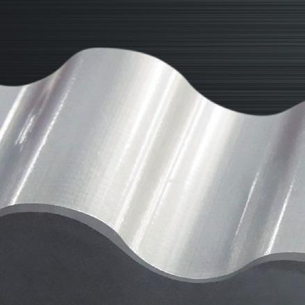
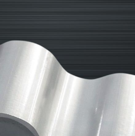
5 RV N SERIES features Smaller Lighter (Compared with our existing products) External dimensions to % smaller (Compared with our existing products) Weight 16 to 36% lighter Model size comparison Model Rated Torque (Nm) Allowable moment (Nm) Allowable thrust (N) Weight (kg) Outside diameter (mm) RV-4E 41 1,666 5, The same basic performance Compact and Lightweight RV-4N 41 1,66 5, Space-saving design for a wide range of uses Robotics Machine tools Food industry Energy Wood processing Semiconductors Medical care Transportation Inspection / measurement 3

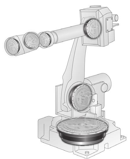


6 Examples of uses for the RV N SERIES TM Vertical-articulated robot (joint shaft) SCARA robot Machine tool (turret of lathe) Machine tool ATC magazine 4
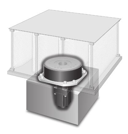
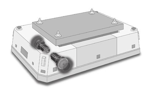
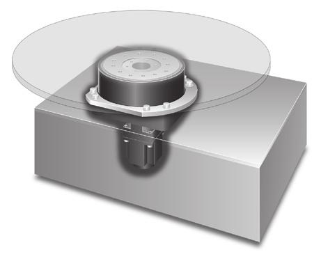
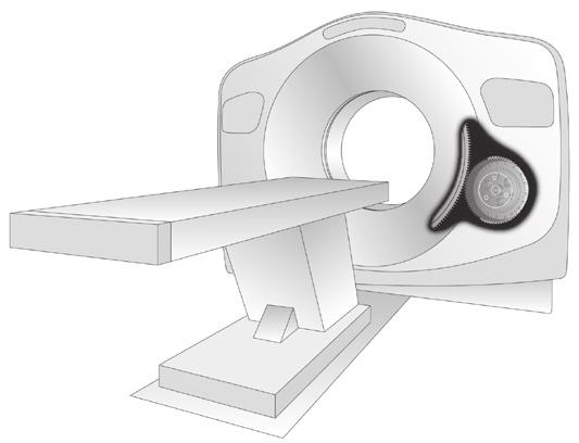


7 Glass substrate/wafer rotation and positioning Positioning turntable Cover open/close and reverser er Medical device AGV drive 5


8 Principle of speed reduction The RV is a -stage reduction gear. 1st stage Spur gear reduction An input gear engages with and rotates spur gears that are coupled to crankshafts. Several overall gear ratios can be provided by selecting various first stage ratios. nd stage Epicyclic gear reduction Crankshafts driven by the spur gears cause an eccentric motion of two epicyclic gears called RV gears that are offset 1 degrees from one another to provide a balanced load. The eccentric motion of the RV gears causes engagement of the cycloidal shaped gear teeth with cylindrically shaped pins located around the inside edge of the case. In the course of one revolution of the crankshafts the teeth of the RV gear move the distance of one pin in the opposite direction of the rotating cranks. The motion of the RV gear is such that the teeth remain in close contact with the pins and multiple teeth share the load simultaneously. The output can be either the shaft or the case. If the case is fixed, the shaft is the output. If the shaft is fixed, the case is the output. Mechanism block diagram Case Pin RV gear Output Input gear Spur gear Shaft Crankshaft nd reduction 1st reduction Speed Ratio The speed ratio is calculated using the formula to the right. R =1+ = 1 R Z Z1 Z4 R : Speed ratio Z1 : Number of teeth on input gear Z : Number of teeth on spur gear Z3 : Number of teeth on RV gear Z4 : Number of pins i : Reduction ratio 6
9 RV TM N SERIES model code Product code RV - 1 N A Model code Frame number Series code Ratio code Input gear code Drawing 5 41, 1, 17.66, 16, 137, P , 1, 15, 16, 141, P. 6 41, 1, 1.17, 11, , 161 P.1 41, 1, 11, 19, 141, 171 P.13 RV 1 N 41, 1, 1.17, 11, 141, 161 A: Standard gear A P.14 41, 1, 1.17, 11, , 161 B: Standard gear B Z: Special or no gear P , 1, 1.1,.1, 6, 1 P , 93, 7, 139, 16, P , 15, 13, 144, 9, P ,, 14.44, 9, 13, 3.5 Refer to pgs. 36 and 37. P.19 *Contact us for more information on this model. Direction of rotation and gear ratio The overall speed ratio i (of the First and Second reduction stages) will differ between shaft rotation and case rotation, and can be calculated from the speed ratio. Shaft rotation Same direction with input Case rotation Reverse direction against input Input Input Output Output The sign "i" in the above equations signifies the output shaft rotation in the same direction as the input shaft."-" signifies the same in the reverse direction. 7
10 Rating table Model RV-5N RV-4N RV-6N RV-N RV-1N RV-N RV-16N RV-3N RV-5N RV-7N R Speed ratio Ratio code Shaft rotation Case rotation /3 3/ /13 1/ /13 1/ /17 17/ /13 1/ /17 17/ /17 17/ /13 1/ / /.1 379/19 36/ /19 34/19 T Rated torque (Note 5) N Rated output Speed K (L 1 ) Rated service life T S1 Allowable acceleration/ deceleration torque T S Momentary maximum allowable torque (Nm) (rpm.) (h) (Nm) (Nm) 45 6, 61 1,5 41 6, 1,9,5 6 6, 1,5 3, 74 6, 1,96 3,9 1, 6,,5 5, 1,5 6, 3,6 6, 1,6 6, 4,, 3,74 6, 9,31 1,6 4,9 6, 1,5 4,5 7, 6, 17,5 35, Note: 1. The allowable output speed will differ depending upon the duty ratio, load, and ambient temperature. Contact us regarding use above the allowable output speed Ns1 with a 4% duty ratio.. The allowable moment will differ depending on the thrust load. Check the allowable moment diagram (P. 9). 3. The inertia moment value is for the reduction gear. It does not include the inertia moment for the input gear. 4. For the moment rigidity and torsional rigidity, refer to the calculation of tilt angle and the torsion angle (p. 3).
11 N S Allowable Output Speed (Note 1) Duty ratio: 1% N S1 Allowable Output Speed (Note 1) Duty ratio: 4% Backlash Lost motion Angular transmission error (Max.) Startup effi ciency (Typical value) M O1 Allowable moment (Note ) M O Momentary allowable moment (Max.) I Reduced value of the inertia moment for the input shaft (Note 3) (rpm.) (rpm.) (arc.min.) (arc.min.) (arc.sec.) (%) (Nm) (Nm) (kgm ) (kg) , ,66 3, , 4, , 4, ,7 5, ,43 6, ,, ,5 14, ,, , 3, 1.71x x x x x x x x x x x x1-6.51x x1-5.6x1-5.33x x x x x x1-5.6x1-5.4x x x x1-5 5.x x x x1-5.59x x x1-5 5.x x x x x x1-4.95x x x x x1-4 3.x1-4.64x x1-9.5x1-7.44x1-6.16x1-5.6x1-4.16x1-1.61x1-1.x1-1.1x1-9.x1 -.4x1-7.46x1 - Note: 5. The rated torque is the value that produces the rated service life based on operation at the rated output speed; it does not indicate the maximum load. Refer to the Glossary (p.) and the Product selection fl owchart (p.3). 6. Contact us regarding speed ratios other than those listed above. 7. The specifi cations above are based on Nabtesco evaluation methods; this product should only be used after confi rming that it is appropriate for the operating conditions of your system. Weight
12 External dimensions Model : RV-5N Specifi cations and dimensions are subject to change without notice. 1
13 Model : RV-4N Specifi cations and dimensions are subject to change without notice.
14 Model : RV-6N Specifi cations and dimensions are subject to change without notice. 1
15 Model : RV-N Specifi cations and dimensions are subject to change without notice. 13
16 Model : RV-1N Specifi cations and dimensions are subject to change without notice. 14
17 Model : RV-N Specifi cations and dimensions are subject to change without notice.
18 Model : RV-16N Specifi cations and dimensions are subject to change without notice. 16
19 Model : RV-3N *Contact us for more information on this model. Specifi cations and dimensions are subject to change without notice. 17
20 Model : RV-5N Specifi cations and dimensions are subject to change without notice. 1
21 Model : RV-7N Specifi cations and dimensions are subject to change without notice. 19
22 Technical Information
23 Considering the use of the RV TM N SERIES This product features high precision and high rigidity, however, it is necessary to strictly comply with various restrictions and make appropriate to maximize the product s features. Please read this technical document thoroughly and select and adopt an appropriate model based on the actual operating environment, method, and conditions at your facility. Export When this product is exported from Japan, it may be subject to the export regulations provided in the Foreign Exchange Order and Export Trade Control Order. Be sure to take suffi cient precautions and perform the required export procedures in advance if the fi nal operating party is related to the military or the product is to be used in the manufacture of weapons, etc. Application If failure or malfunction of the product may directly endanger human life or if it is used in units which may injure the human body (atomic facilities, space equipment, medical equipment, safety units, etc.), examination of individual situations is required. Contact our agent or nearest business offi ce in such a case. Safety measures Although this product has been manufactured under strict quality control, a mistake in operation or misuse can result in breakdown or damage, or an accident resulting in injury or death. Be sure to take all appropriate safety measures, such as the installation of independent safeguards. Product specifications indicated in this catalog The specifi cations indicated in this catalog are based on Nabtesco evaluation methods. This product should only be used after confi rming that it is appropriate for the operating conditions of your system. Operating environment Use the reduction gear under the following environment: Location where the ambient temperature is between -1 C to 4 C. Location where the humidity is less than 5% and no condensation occurs. Location where the altitude is less than 1 m. Well-ventilated location Note 1: : Maintenance The standard replacement time for grease is, hours. However, when operation involves a reduction gear surface temperature above 4 C, the state of degradation of the lubricant should be checked in advance of that and the grease replaced earlier as necessary. Reduction gear temperature When the reduction gear is used under high load and at a high duty ratio, it may overheat and the surface temperature may exceed the allowable temperature. Be aware of conditions so that the surface temperature of the reduction gear does not exceed 6 C while it is in operation. There is a possibility of damage (to the product) if the surface temperature exceeds 6 C. Reduction gear output rotation angle Do not install the reduction gear at the following locations. Location where a lot of dust is collected. Outdoors that can be directly affected by wind and rain Location near the environment that contains combustible, explosive, or corrosive gases and flammable materials. Location that is heated due to heat transfer and radiation from peripherals and direct sun. Location where the performance of the servo motor can be affected by magnetic fields or vibration. If the required operating environment cannot be established/met, contact us in advance. When using the reduction gear under special conditions (clean room, equipment for food, concentrated alkali, high-pressure steam, etc.), contact our agent or nearest business office in advance. When the range of the rotation angle is small (1 degrees or less), the service life of the reduction gear may be reduced due to poor lubrication or the internal parts being subject to a concentrated load. Note: Contact us in case the rotation angle is 1 degrees or less. Manuals Safety information and detail product instructions are indicated in the operation manual. The operation manual can be downloaded from the following web address. 1
24 Glossary Rating service life The lifetime resulting from the operation with the rated torque and the rated output speed is referred to as the rated service life. Allowable acceleration/deceleration torque When the machine starts or stops, the load torque to be applied to the reduction gear is larger than the constant-speed load torque due to the effect of the inertia torque of the rotating part. In such a situation, the allowable torque during acceleration/deceleration is referred to as allowable acceleration/deceleration torque. Note: Be careful that the load torque, which is applied at startup and stop, does not exceed the allowable acceleration/deceleration torque. Momentary maximum allowable torque A large torque may be applied to the reduction gear due to execution of emergency stop or by an external shock. In such a situation, the allowable value of the momentary applied torque is referred to as momentary maximum allowable torque. Note: Be careful that the momentary excessive torque does not exceed the momentary maximum allowable torque. Load torque Momentary max torque Max torque for startup Constant torque Max torque for stop Time Allowable output speed The allowable value for the reduction gear s output speed during operation without a load is referred to as the allowable output speed. Notes: Depending on the conditions of use (duty ratio, load, ambient temperature), the reduction gear temperature may exceed 6 C even when the speed is under the allowable output speed. In such a case, either take cooling measures or use the reduction gear at a speed that keeps the surface temperature at 6 C or lower. Duty ratio The duty ratio is defined as the ratio of the sum total time of acceleration, constant, and deceleration to the cycle time of the reduction gear. Torsional rigidity, lost motion, backlash When a torque is applied to the output shaft while the input shaft is fixed, torsion is generated according to the torque value. The torsion can be shown in the hysteresis curves. The value of b/a is referred to as torsional rigidity. The torsion angle at the mid point of the hysteresis curve width within ±3% of the rated torque is referred to as lost motion. The torsion angle when the torque indicated by the hysteresis curve is equal to zero is referred to as backlash. Hysteresis curve Startup Efficiency The efficiency of the moment when the reduction gear starts up is referred to as startup efficiency. No-load running torque (input shaft) The torque for the input shaft that is required to run the reduction gear without load is referred to as no-load running torque. Allowable Moment and Maximum Thrust Load The external load moment may be applied to the reduction gear during normal operation. The allowable values of the external moment and the external axial load at this time are each referred to as allowable moment and maximum thrust load. Angular transmission error The angular transmission error is defined as the difference between the theoretical output angle of rotation (when there are input instructions for an arbitrary rotation angle) and the actual output angle of rotation. Angular transmission error (sec) Backlash Torsion angle ±3% Rated Torque ±1% Rated Torque 3 sec b Lost motion a One revolution of the output shaft (degrees)
25 Product selection Product selection flowchart Step 1. Set items required for selection. Setting of equipment to be verified Reduction gear mounting direction NO Review load conditions. Re-evaluate operation pattern. YES Setting of operation conditions Weight of the equipment to be verified Cycle time Configuration of the equipment to be verified Operating hours per day Rotation angle Operating days per year Rotation time Step. Verify the operating environment. Checking of operating environment Ambient temperature Locations where the product Humidity cannot be installed Altitude (Refer to page 1.) Ventilation Reduction gear surface temperature Compatible NO YES Step 3. Verify the reduction gear load. 1.Calculation of inertia moment.calculation of constant torque 3.Setting of input type 4.Setting of operation pattern 5.Calculation of inertia torque 6.Calculation of load torque 7.Calculation of average speed and average load torque Step 4. Select a reduction gear. Calculate the rated torque that satisfies the required life and select a reduction gear. NO Reduction gear selection method(1) YES Reduction gear selection method() Select a reduction gear based on the calculated rated torque. Tentatively select a reduction gear model. Verify the maximum torque for startup. TA T S1 NO Verify the maximum torque for startup. T A T S1 NO YES YES Verify the output speed. N N S YES NO Verify the output speed. N N S YES Verify the thrust load W Allowable thrust. NO NO Verify the thrust load W Allowable thrust. YES NO YES Verify the moment load. M M O NO YES Examine the moment load. M O M YES NO Reconsider the appropriate model. YES NO Verify the service life. L L ex YES NO Reconsider the appropriate model. YES NO Determine the reduction gear model. 3
26 Product selection Model code selection examples With horizontal rotational transfer Step 1. Set the items required for selection. Setting item Setting a Work P.C.D.:D Reduction gear mounting direction Equipment weight to be considered Vertical shaft installation b W A Disk weight (kg) 1 W B Work weight (kg) 4 pieces Equipment configuration to be considered D 1 Disk: D dimension (mm) 1, a Work piece: a dimension (mm) 1 Fixing component Reduction gear D1 Servo motor Equipment to be verified: Work Equipment to be verified: Disk Motor flange b Work piece: b dimension (mm) 3 D Work piece: P.C.D. (mm) 1, Operation conditions Rotation angle ( )* 1 1 [t 1 +t +t 3 ] Rotation time (sec).5 [t 4 ] Cycle time (sec) Q 1 Equipment operation hours per day (hours/day) 1 Q Equipment operation days per year (days/year) 365 *1. When the range of the rotation angle is small (1 degrees or less), the rating life of the reduction gear may be reduced due to poor lubrication or the internal parts being subject to a concentrated load. Step. Verify the operating environment. Checkpoint S Ambient temperature ( C) -1 to +4 Standard value S1( C) Speed (rpm.) Load torque (Nm) 6 4 Time (s) S 1 Reduction gear surface temperature ( C) 6 or less -1 Note: Refer to Operating environment on p. 1 for values other than those listed above. Step 3-1. Examine the reduction gear load -1 S ( C) 4 Setting item Calculation formula Selection examples 1.Calculate the inertia moment based the calculation formula on page 4. I R Load inertia moment (kgm ) D1 WA 1, I R1 = WB a b D I R = + + WB 1 1, 1, 1, I R1 = Disk inertia moment I R = Work inertia I R = I R1 + I R n = Number of work pieces n 1, 1 1, I R1 = = 3.4 ( kgm ) I R = I R 1 =.7 = = 53.1 ( kgm) 1 1, 3 + 1, + 1, 1, 4.Examine the constant torque. T R Constant torque (Nm) Din TR = ( WA + WB ) 9. 1, μ μ = Friction factor Note: Use. for this example as the load is applied to the bearing of the RD reduction gear. Din = Rolling diameter: Use the pilot diameter which is almost equivalent to the rolling diameter in this selection calculation. Note: If the reduction gear model is not determined, select the following pilot diameter: Maximum pilot diameter: 353 (mm) T R ( ) 353 = , = 6.7(Nm) Step 3-: Proceed to p. 6. 4
27 With vertical rotational transfer Step 1. Set the items required for selection. Setting item Setting Reduction gear mounting direction Horizontal shaft installation Equipment weight to be considered Reduction gear Motor flange Servo motor Fixing component Equipment to be examined W C Mounted work weight (kg) 49 a Equipment configuration to be considered a a dimension (mm) 5 b b dimension (mm) 5 R R dimension (mm) 3 Operation conditions R Position of the center of gravity Rotation center b Rotation angle ( )* 1 9 [t 1 +t +t 3 ] Rotation time (sec) 1.5 [t 4 ] Cycle time (sec) Load torque (Nm) Q 1 Equipment operation hours per day (hours/day) 4 Q Equipment operation days per year (days/year) 365 *1. When the range of the rotation angle is small (1 degrees or less), the rating life of the reduction gear may be reduced due to poor lubrication or the internal parts being subject to a concentrated load. Rotation speed (rpm.) Step. Verify the operating environment. 6 Time (s) Checkpoint Standard value S Ambient temperature ( C) -1 to +4 S 1 Reduction gear surface temperature ( C) 6 or less Note: Refer to Operating environment on p. 1 for values other than those listed above. S1( C) 4-1 Step 3-1. Examine the reduction gear load -1 S ( C) 4 Setting item Calculation formula Selection examples 1.Calculate the inertia moment based the calculation formula on page 4. I R Load inertia moment (kgm ) = WC I R 1 a + b + W R C 1, 1, 1, 49 5 I R = + 1 1, = 7.6( kgm) 5 1, ,.Examine the constant torque. T R Constant torque (Nm) R TR = WC 9. 1, T R = = 1,537(Nm) 3 1, Step 3-: Proceed to p. 6. (Refer to With horizontal rotational transfer for selection examples.) 5
28 Step 3-. Set items required for selection Setting item Calculation formula Selection examples (With horizontal rotational transfer) (3) Set the acceleration/deceleration time, constant-speed operation time, and output speed. t 1 t t 3 N N 1 Acceleration time (sec) Constant-speed operation time (sec) Deceleration time (sec) Constant speed (rpm.) Average speed for startup N N 1 = (rpm.) The operation pattern does not need to be verifi ed if it is already set. If the operation pattern has not been determined, use the following formula to calculate the reference operation pattern. t1 = t3 = Rotation t1 + t + t3 N 36 6 t = Rotation t1 + t + t3 ( t1 + t3) Note: 1. Assume that t1 and t3 are the same. Note:. N = rpm. if the reduction gear output speed (N) is not known. Note: 3. If t1 and t3 is less than, increase the output speed or extend the rotation time. Examine the operation pattern using N = rpm. as the reduction gear output speed is unknown. 1 t1 = t 3 =.5 =.5( sec) 36 6 t =.5 (.5+.5) = 1.5 ( sec) t1 = t 3 =.5 (sec) t = 1.5 (sec) N = (rpm.) N1 = = 7. 5 (rpm.) N 3 Average speed for stop (rpm.) N = 3 N N 3 = = 7. 5 (rpm.) (4) Calculate the inertia torque for acceleration/deceleration. T A Inertia torque for acceleration (Nm) T = A IR ( N ) t 1 6 π T A 53.1 ( ) =.5 = 166.(Nm) π 6 T D Inertia torque for deceleration (Nm) T = D I R ( N ) t 3 π 6 T o 53.1 ( ) =.5 = 166.(Nm) π 6 (5) Calculate the load torque for acceleration/deceleration. T 1 Maximum torque for startup T1 = TA + TR (Nm) T R : Constant torque See page 4. T1 = = (Nm) T Constant maximum torque (Nm) T R T = 6.7 (Nm) T = T 3 Maximum torque for stop T1 = TA + TR (Nm) T R : Constant torque See page 4. T = = 16.1(Nm) (6)-1 Calculate the average speed. N m Average speed (rpm.) t1 N1+ t N+ t 3 N N m = t + t + t N m = = 1(rpm.) (6)- Calculate the average load torque. T m Average load torque (Nm) 1 3 t T1 + t T + t3 T N N N = m t N + t N + t N T T m = =.3 (Nm) 1 3 Go to Page 7 if the reduction gear model is verified based on the required life. Go to Page if the service life is verified based on the reduction gear model. 6
29 Step 4. Select a reduction gear Reduction gear selection method (1) Calculate the required torque based on the load conditions and required life and select a reduction gear. Setting item Calculation formula Selection examples (With horizontal rotational transfer) (1) Calculate the rated torque for the reduction gear that satisfi es the required life. L ex Required life (year) Based on the operation conditions 5 years Q 1cy Number of cycles per day Q1 6 6 Q (times) 1 cy = t4 Q1 cy = =,16 (times) Q 3 Operating hours of reduction gear per day (h) Q1 cy ( t1+ t + t3 ) Q3 = 6 6,16 ( ) Q3 = 6 6 = 1.5( h) Q 4 Operating hours of reduction Q gear per year (h) 4 = Q3 Q Q4 = = 54 ( h) Lhour = 54 5 L hour Reduction gear service life (h) Lhour = Q 4 Lex =,74 ( h) T O' Reduction gear rated torque that satisfi es the required life (Nm) 1 Lhour T' N = T 3 m m K N K : Reduction gear rated life (h) N : Reduction gear rated output speed (rpm.) T' =.3 1 3,74 1 6, = 1.5(Nm) () Select a reduction gear model based on the calculated rated torque. Tentative selection of the reduction gear model and actual reduction ratio W 1 L 1 W L M Radial load (N) Distance to the point of radial load application (mm) Thrust load (N) Distance to the point of thrust load application (mm) Calculation of the moment load (Nm) Determination of the reduction gear model Tentatively select a reduction gear model that T is equal to or greater than T. Then check that T S1 of the tentatively selected model is equal to or greater than the maximum torque for startup T 1 and N S of the tentatively selected model is equal to or greater than the output speed N. If the tentatively selected reduction gear is outside of the specifi cations, increase the reduction gear model. T S1, Ns: Refer to the rating table on page. NS: The allowable output speed varies depending on the actual reduction ratio. Tentatively select the actual reduction ratio alongside the allowable output speed. L W1 W L1 a b W1 ( L 1+ b-a) + W L M = 1, a,b: Refer to the calculation of the tilt angle on page 3. From the allowable moment diagram on Page 9 Thrust load Moment load Select a reduction gear for which the above fall within the allowable moment diagram. The actual reduction ratio is determined based on the motor speed, input torque, and inertia moment. Check with the motor manufacturer. Selection of the motor fl ange and bushing. Motor momentary maximum T M1 Determine based on the motor specifi cations. torque (Nm) T M1OUT Maximum torque generated at the output shaft for the reduction gear (Nm) TM 1out = TM 1 R R :Actual reduction ratio :Startup efficiency(%) Note: If the maximum torque generated at the output shaft for the reduction gear exceeds the momentary maximum allowable torque, impose a limitation on the motor torque value. Also, ensure that the shock torque, due to an emergency stop, is the same as or lower than the momentary maximum allowable torque. Tentatively select RV-5N (T = 45 Nm) based on the calculated rated torque. Rated torque: 45 (Nm) 1.5 (Nm) Allowable acceleration/deceleration torque: 613 (Nm) (Nm) Allowable output speed: 57 (rpm.) (when the actual reduction ratio is 33.45) is equal to or greater than (rpm.), tentatively selecting RV-5N should be no problem. (N) (mm) W = ( 1 + 4) 9. =,54 ( N) (mm) As dimension a =.1 (mm) and dimension b =.4 (mm): ( ) +,54 M = 1, = (Nm) For this example, Thrust load W =,54 (N) Moment load M = (N) As the above values are within the RV-5N allowable moment diagram, RV-5N is selected. For example, TM1 = 5 (Nm) For example, calculate the maximum torque generated at the output shaft for the reduction gear based on the specifi - cations when RV-5N was selected. T = M1out TM 1 R = = 3,1 (Nm) 1 As TM1out is equal to or greater than Ts (1,33 Nm), a limitation is required for the motor torque. 7
30 Reduction gear selection method (): Tentatively select a reduction gear model and evaluate the service life. Setting item Calculation formula Selection examples (With horizontal rotational transfer) (1) Select a reduction gear model based on the maximum torque for startup T1, output speed N, thrust load, and moment load. Tentative selection of the reduction gear model and actual reduction ratio If TS1 of the tentatively selected model is equal to or greater than the maximum torque for startup T1 and the tentatively selected model is outside of the reduction gear specifi cations, upgrade the reduction gear model. TS1, Ns: Refer to the rating table on page. NS: The allowable output speed varies depending on the actual reduction ratio. Tentatively select the actual reduction ratio alongside the allowable output speed. W 1 R adial load (N) (N) L 1 Distance to the point of radial load application (mm) (mm) W L M Thrust load (N) Distance to the point of thrust load application (mm) Calculation of the moment load (Nm) L W1 W L1 a b W1 ( L 1+ b-a) + W L M = 1, a,b: Refer to the calculation of the tilt angle on page 3. From the rating table on page : Allowable acceleration/deceleration torque: 613 (Nm) (Nm) Allowable output speed: 57 (rpm.) is equal to or greater than (rpm.), tentatively select RV-5N. W = ( 1 + 4) 9. =,54 ( N) (mm) RV-5N As dimension a =.1 (mm) and dimension b =.4 (mm): ( ) +,54 M = 1, = (Nm) Determination of the reduction gear model From the allowable moment diagram on Page 9 Thrust load Moment load Select a reduction gear for which the above fall within the allowable moment diagram. The actual reduction ratio is determined based on the motor speed, input torque, and inertia moment. Check with the motor manufacturer. For this example, Thrust load W =,54 (N) Moment load M = (N) As the above values are within the RV-5N allowable moment diagram, RV-5N is selected. () Calculate the reduction gear service life and compare to the required life. L h Life (h) N L h = 6, N m T T m 1 3 L h = 6, 1 = 17, Q 1cy Number of cycles per day (times) = Q1 cy = =,16 (times) Q1 6 Q1 cy t 4 Q 3 Operating hours per day (h) Q1 ( t1+ t + t 3) Q3 = 6 6,16 ( ) Q3 = = 1. 5 ( h) 6 6 Q 4 Operating hours per year (h) Q 4 = Q3 Q Q4 = = 54( h) L year Reduction gear service life (year) Lyear L 17,4 = Lyear = = ( year) 54 h Q 4 L ex Required life (year) Based on the required specifi cations. If the required life is longer than the service life, upgrade the reduction gear model and re-calculate the service life. Cautions for selecting a motor Motor momentary maximum T M1 Determine based on the motor specifi cations. torque (Nm) T M1OUT Maximum torque generated at the output shaft for the reduction gear (Nm) T R R M 1out = TM 1 :Actual reduction ratio :Startup efficiency(%) Note: If the maximum torque generated at the output shaft for the reduction gear exceeds the momentary maximum allowable torque, impose a limitation on the motor torque value. Also, ensure that the shock torque, due to an emergency stop, is the same as or lower than the momentary maximum allowable torque. As Lex 5 (year) is equal to or less than (year), the reduction gear model is RV-5N. For example, TM1 = 5 (Nm) For example, calculate the maximum torque generated at the output shaft for the reduction gear based on the specifi - cations when RV-5N was selected. TM1out = TM 1 R = = 3,1 (Nm) 1 As TM1out is equal to or greater than Ts (1,5 Nm), a limitation is required for the motor torque.
31 Product selection Allowable moment diagram RV-5N, 4N, 6N, N, 1N 1, 9, RV-1N Thrust Load (N) 6,53 5, 5, 4,1 3,7 3,57 3,3,61 RV-4N RV-5N RV-6N RV-N 1,3 74 1,66 1,6,,16,7 75 1,49 1,77, Allowable Moment (Nm) 3, RV-N, 16N, 3N, 5N, 7N 5, 44, Thrust Load (N) 3, 5, 14,7 13, 1,1 1,63 7,45 5,41 5, 7,, 16,,5 3,43 4,1,,79 4, 7,56,1 Allowable Moment (Nm) 9
32 Technical data No-load running torque Use the following formula to calculate the no-load running torque converted to the motor shaft. No-load running torque converted to the motor shaft (Nm) = Torque converted into the output shaft (Nm) R (R: speed ratio value) [Measurement conditions] Lubricant: Grease (VIGOGREASE RE) Note: The values in the following graphs are for the reduction gear alone, and indicate the average values after the break-in period. RV-5N, 4N, 6N No-load running torque (Reduced for the output shaft) (Nm) 1 6N 16 4N N Output shaft rotation speed (rpm.) RV-N, 1N, N, 16N No-load running torque (Reduced for the output shaft) (Nm) 35 16N N 3 1N 5 N Output shaft rotation speed (rpm.) RV-3N, 5N, 7N No-load running torque (Reduced for the output shaft) (Nm) 1 7N 5N 1 6 3N Output shaft rotation speed (rpm.) 3
33 Technical data Low temperature characteristic When the RV-N reduction gear is used at a low temperature, viscosity of lubricant increases and causes a larger no-load running torque. The no-load running torque at low temperature is shown below. [Measurement conditions] Input speed:, rpm. Use the following formula to calculate the no-load running torque converted to the motor shaft. Lubricant: Grease (VIGOGREASE RE) Torque converted into the output shaft (Nm) No-load running torque converted to the motor shaft (Nm) = (R: speed ratio value) R RV-5N, 4N, 6N No-load running torque (Reduced value for the output shaft) (Nm) 7 6 6N 5 4 4N 3 5N Case temperature [ C] RV-N, 1N, N, 16N No-load running torque (Reduced value for the output shaft) (Nm) 1,6 16N 1,4 1, 1, N 1N N Case temperature [ C] RV-3N, 5N, 7N Note: Contact us regarding use of the RV-7N at a low-temperature environment. No-load running torque (Reduced value for the output shaft) (Nm) 6, 5N 5, 4, 3N 3,, 1, Case temperature [ C] 31
34 Technical data Calculation of tilt angle and torsion angle Calculation of tilt angle When a load moment occurs with an external load applied, the output shaft will tilt in proportion to the load moment (If R3 is larger than b, and R is larger than c/) The moment rigidity indicates the rigidity of the main bearing, and it is represented by the load moment value required for tilting the main bearing by 1 arc.min. Output shaft installation surface = W1l1 Wl M1 3 : Tilt angle of the output shaft (arc.min.) M1 : Moment rigidity (Nm/arc.min.) W1, W : Load (N) l1, l : Distance to the point of load application (mm) l1 :l l : Distance from the output shaft installation surface to the point of load application (mm) Model Moment rigidity (central value) Nm/arc.min. Dimensions (mm) a b c Model Moment rigidity (central value) Nm/arc.min. Dimensions (mm) a b c RV-5N RV-N 1, RV-4N RV-16N, RV-6N 1, RV-3N 5, RV-N 1, RV-5N 6, RV-1N 1, RV-7N 9, Calculation of torsion angle Calculate the torsion angle when the torque is applied in a single direction, using an example of RV-16N. 1) When the load torque is 3 Nm...Torsion angle (ST 1 ) When the load torque is 3% or less of the rated torque 3 ST1 = 4. 1 (arc.min.) =.31(arc.min.) or less ) When the load torque is 1,3 Nm...Torsion angle (ST ) When the load torque is more than 3% of the rated torque ST = 1 1, = 1.(arc.min.) Note: 1. The torsion angles that are calculated above are for a single reduction gear. Model RV-5N RV-4N RV-6N RV-N RV-1N Torsional rigidity (central value) Nm/arc.min Lost motion arc.min. Lost motion Measured torque Nm Backlash arc.min. ±7.35 ± ±1. 1. ±3.5 ±3. Model RV-N RV-16N RV-3N RV-5N RV-7N Torsional rigidity (central value) Nm/arc.min ,6,6 Lost motion Lost motion Measured torque arc.min. Nm ±36. ±4. 1. ± ±147 ±1 Backlash arc.min. 1. 3
35 Design points Reduction gear installation components Installation of the reduction gear and mounting it to the output shaft When installing the reduction gear and mounting it to the output shaft, use hexagonal socket head cap screws and tighten to the torque, as specified below, in order to satisfy the momentary maximum allowable torque, which is noted in the rating table. The use of the Belleville spring washers are recommended to prevent the bolt from loosening and protect the bolt seat surface from flaws. <Bolt tightening torque and tightening force> Hexagon socket head cap screw nominal size x pitch (mm) Tightening torque (Nm) Tightening force F (N) Bolt specification M5. M6 1. M 1.5 M1 1.5 M M ±.49.6 ± ± ± ± ±.9 9,31 13,1 3,96 3, 55,36 13,41 Hexagon socket head cap screw JIS B 76 or equivalent (ISO 476) Strength class JIS B or equivalent (ISO 9-1) Thread JIS B 5 6 g or class or Equivalent Note: 1. The tightening torque values listed are for steel or cast iron material.. If softer material, such as aluminum or stainless, is used, limit the tightening torque. Also take the transmission torque and load moment into due consideration. <Calculation of allowable transmission torque of bolts> D T = F 1, n T F D μ n Allowable transmission torque by tightening bolt (Nm) Bolt tightening force (N) Bolt mounting P.C.D (mm) Friction factor μ=.: When grease remains on the mating face. μ=.: When grease is removed from the mating face. Number of bolts (pcs.) <Serrated lock washer external teeth for hexagonal socket head cap screw> Name:Belleville spring washer (made by Heiwa Hatsujyo Industry Co., Ltd.) Corporation symbol: CDW-H-Nominal size CDW-L-5 (Only for M5) Material: S5C to S7C Hardness: HRC 4 to 4 (Unit: mm) ID and OD of Belleville Nominal spring washer size d t H Basic D size d H t D Note: When using any equivalent washer, select it with special care given to its outside diameter. 33
36 Design of the motor mounting flange In order to avoid contact with reduction gear components, refer to the sizes indicated in the Outer dimensions drawings when designing the motor mounting flange. Note: The size and number of bolts for the motor mounting flange should be determined with the torque and moment taken into consideration, and should be positioned in line with the reduction gear s case mounting holes. After installing the reduction gear, we recommend installing an add/drain grease fitting to enable grease replacement. An installation example is shown below. Use the specified tightening torque to uniformly tighten the hexagonal socket head cap screws (with corresponding conical spring washers). Design the motor mounting flange to the following accuracy. Case mounting holes If the installation accuracy is poor, it will result in vibration and noise. Add/Drain grease fitting <Installation accuracy> Model Concentricity tolerance mm Model Concentricity tolerance mm RV-5N MAX.3 RV-N MAX.3 RV-4N MAX.3 RV-16N MAX.3 RV-6N MAX.3 RV-3N MAX.5 RV-N MAX.3 RV-5N MAX.5 RV-1N MAX.3 RV-7N MAX.5 O-Ring (I) Suited O-rings for O-Ring (I) in the diagram above are indicated in the following tables. Refer to these tables when designing seals for the installation components. <O-Ring (I)> Model O-ring number Model O-ring number RV-5N S RV-N AS RV-4N AS56-9 RV-16N AS56-17 RV-6N AS56-5 RV-3N AS56-7 RV-N AS56-5 RV-5N AS56-75 RV-1N AS RV-7N G34-1A Design of the case and shaft installation components Align the case bolt holes with the taps on the installation components, and the taps on the shaft with the installation component bolt holes, and install the case with the designated number of bolts. Use the specified tightening torque to uniformly tighten the hexagonal socket head cap screws (with corresponding conical spring washers). Use either the outside or inside fit for the shaft. After installing the reduction gear, we recommend installing an add/drain grease fitting to enable grease replacement. An installation example is shown at right. Bolt holes for shaft installation component Outside fit Inside fit Add/Drain grease fitting Note: Since the sizes of the bolts for tightening the shaft differ, always verify after installation that each bolt has been tightened at the specified torque. Tap for case installation component Conical spring washer 34
37 Suited O-rings for O-Ring (I) in the diagram above are indicated in the following tables. Refer to these tables when designing seals for the installation components. <For RV-5N, 4N, 6N, N, 1N and N models> Seal with Diestat or other comparable product. Seals for the conical spring washers are not necessary. <For RV-16N, 3N, 5N and 7N models> Shaft installation component Add/Drain grease fitting Shaft installation component Add/Drain grease fitting O-ring (II) O-ring (II) groove detailed view Note: The output shaft on these models does not have an O-ring groove. Prepare a groove for an O-ring in the shaft installation component. Use Daistat or other comparable product to seal the tightening side of the shaft installation component bolt. Note: Use an O-ring groove on the reduction gear output surface for these models. <O-Ring (II)> Model Bearing number O-ring groove dimensions O.D. (D) Depth (H) Width (G) Model Bearing number O-ring groove dimensions O.D. (D) Depth (H) Width (G) RV-5N G5 9±.1.4± / RV-N G145 ±.1.4± / RV-4N G 5±.1.4± / RV-16N G13 Use the reduction gear O-ring groove. RV-6N G13 135±.1.4± / RV-3N G145 Use the reduction gear O-ring groove. RV-N G13 135±.1.4± / RV-5N G Use the reduction gear O-ring groove. RV-1N G145 ±.1.4± / RV-7N G Use the reduction gear O-ring groove. When an O-ring cannot be used for structural reasons, use one of the liquid gaskets or other sealant indicated in the following table. Refer to the diagram at right and apply the sealant so that it does not get inside the reduction gear and does not leak out of the shaft installation bolt hole. Example application <Recommended liquid sealant> Name (Manufacturer) ThreeBond 1 (ThreeBond Co.) HermeSeal SS-6F (Nihon Hermetics Co.) Loctite 5 (Henkel) Characteristics and applications Silicone-based, solventless type Semi-dry gasket One-part, non-solvent elastic sealant Metal contact side (flange surface) seal Any product basically equivalent to ThreeBond 1 Anaerobic flange sealant Metal contact side (flange surface) seal Note: 1. Do not use for copper or a copper alloy.. Contact us regarding use under special conditions (concentrated alkali, high-pressure steam, etc.). Area to apply liquid sealant 35
38 Design points Input gears Installation of the input gear The following shows examples of the shape of the servo motor shaft and installation of the input gear. Refer to the following diagram when designing the input gear. (The setscrew, drawbolt, and hex nut must be supplied by your company.) Note: Locate the setscrew to the motor side of the oil seal contact. <For straight shafts> Without internal threads in the servo motor Setscrew With internal threads in the servo motor Seal with a seal washer or other washer. <For tapered shafts> With male screw on the servo motor Seal with a seal washer or other washer. Hexagonal socket head cap screw Hex nut Drawbolt Design of the input gear Use a standard input gear and drill holes to anchor the motor shaft and prepare the oil seal surface. The oil seal surface should be the value indicated by D in the Dimensions table, and the LB section should be finished by plunge grinding. Standard input gears come equipped with center holes on both-sides. Polish the outside diameter of area D1 to achieve the reference level and then perform processing of the inside diameter of the anchor holes for the motor shaft. Parts not indicated in the Dimensions table should have a minimum thickness of 3 mm. Note: When incorporating an input gear, be careful not to obstruct the spur gear and thus damage the gear. Damage to the gear will result in abnormal noise. <Shape of the standard input gear> LF <Standard input gear A> D (Plunge cutting range) D4 LD LE LA LC MIN (Motor shaft tip position) L LB (Plunge cutting range) Carburizing prevention range D3 MAX D1 <Standard input gear B> LA L D (Plunge cutting range) D4 LD LE LC MIN (Motor shaft tip position) LB (Plunge cutting range) Carburizing prevention range D3 MAX D1 36
39 <Model: RV-5N> D Standard input gear A Standard input gear B (unit:mm) Ratio Motor shaft diameter: less than mm Motor shaft diameter: mm or more LF Before After D3 D4 LE LD +. code plunge plunge L LA LB LC D1 L LA LB LC D1 cutting cutting h <Model: RV-4N> D Standard input gear A Standard input gear B (unit:mm) Ratio Motor shaft diameter: less than 3 mm Motor shaft diameter: 3 mm or more LF Before After D3 D4 LE LD +. code plunge plunge L LA LB LC D1 L LA LB LC D1 cutting cutting h <Model: RV-6N> D Standard input gear A Standard input gear B (unit:mm) Ratio Motor shaft diameter: less than 3 mm Motor shaft diameter: 3 mm or more LF Before After D3 D4 LE LD +. code plunge plunge L LA LB LC D1 L LA LB LC D1 cutting cutting h <Model: RV-N> D Standard input gear A Standard input gear B (unit:mm) Ratio Motor shaft diameter: less than 3 mm Motor shaft diameter: 3 mm or more LF Before After D3 D4 LE LD +. code plunge plunge L LA LB LC D1 L LA LB LC D1 cutting cutting 55h <Model: RV-1N> (unit:mm) Ratio code LF 73.9 Before plunge cutting 6.4 D After plunge cutting 6h D D4 9 LE LD Standard input gear A Motor shaft diameter: 4 mm or less LA LB LC D1 L <Model: RV-N> (unit:mm) Ratio code LF 76. Before plunge cutting 6.4 D After plunge cutting 6h D D4 9 LE LD Standard input gear A Motor shaft diameter: 4 mm or less LA LB LC D1 L <Model: RV-16N> (unit:mm) Ratio code LF 3.4 Before plunge cutting 65.4 D After plunge cutting 65h D D4 9 LE LD Standard input gear A Motor shaft diameter: 4 mm or less LA LB LC D1 L <Model: RV-3N> (unit:mm) Ratio code LF Before plunge cutting D After plunge cutting h D D4 LE LD Standard input gear A Motor shaft diameter: less than 55 mm L LA LB LC D Standard input gear B Motor shaft diameter: 55 mm or more L LA LB 1 LC D1 7 <Model: RV-5N> D Standard input gear A Standard input gear B (unit:mm) Ratio Motor shaft diameter: less than 55 mm Motor shaft diameter: 55 mm or more LF Before After D3 D4 LE LD +. code plunge plunge L LA LB LC D1 L LA LB LC D1 cutting cutting h <Model: RV-7N> D Standard input gear A Standard input gear B (unit:mm) Ratio Motor shaft diameter: less than 55 mm Motor shaft diameter: 55 mm or more LF Before After D3 D4 LE LD +. code plunge plunge L LA LB LC D1 L LA LB LC D1 cutting cutting 65h
Precision Reduction Gear RV TM. N Series
 Precision Reduction Gear RV TM N Series Nabtesco's technologies o es supporting port society Contributing to society with our Moving it. Stopping it. technologies Nabtesco manufactures products which are
Precision Reduction Gear RV TM. E Series / C Series / Original Series
 Precision Reduction Gear RV TM E Series C Series Original Series Nabtesco's technologies o es supporting port society Contributing to society with our Moving it. Stopping it. technologies Nabtesco manufactures
Precision Reduction Gear RV TM Compact Actuator
 Precision Reduction Gear RV TM Compact Actuator AF Series Nabtesco's technologies o es supporting port society Contributing to society with our Moving it. Stopping it. technologies Nabtesco manufactures
Precision Reduction Gear RV TM. Precision Gearhead. RD2 Series
 Precision Reduction Gear RV TM Precision Gearhead RD Series Nabtesco's technologies supporting society Contributing to Society with Our Moving it. Stopping it. Technologies Nabtesco manufactures products
Precision Reduction Gear RV TM
 Precision Reduction Gear RV TM Turntable Gearhead RS Series Nabtesco's technologies supporting society Contributing to society with our Moving it. Stopping it. technologies Nabtesco manufactures products
GAM New Products 2018
 GAM New Products 218 GPL ROBOTIC PLANETARY GCL ROBOTIC CYCLOIDAL EPR RIGHT ANGLE BEVEL PLANETARY VP PRECISION PLUS SPIRAL BEVEL GAM Can. GAM Company Overview About GAM Founded in 199 by Gary A. Michalek,
NEW LM Actuator. US Only. Optimal for high speed and long stroke Long term maintenance-free operation is actualized Lightweight, compact structure
 NEW LM Actuator Optimal for high speed and long stroke Long term maintenance-free operation is actualized Lightweight, compact structure TY US Only CATALOG No.352E Structure of Model TY This belt drive
The CSF-mini series now includes Ultra Flat models with High-Moment Stiffness
 New Product News Vol. 22 Toll Free Speed Phone (877) SERVO98 Sensor Toll Reducer Free Fax (877) SERV99 Controller Motor Other System Elements Driver The CSF-mini series now includes Ultra Flat models with
High performance metal disk coupling SERVOFLEX SFF (N)
") High performance metal disk coupling SERVOFLEX SFF (N) Best design for the latest servo motor SERVOFLEX for feed shaft which introduce the high precision clamp method Coupling outer diameter, lineup for
High performance metal disk coupling SERVOFLEX SFF (N) Best design for the latest servo motor SERVOFLEX for feed shaft which introduce the high precision clamp method Coupling outer diameter, lineup for
Courtesy of Steven Engineering, Inc - (800) PATENTED
 PATENTED") PRECISION RING DRIVE SYSTEMS Based on Nexen s innovative Roller Pinion technology, Nexen Ring Drive Systems come complete with a precision grade, high capacity bearing and drive mechanism in a rigid housing.
PRECISION RING DRIVE SYSTEMS Based on Nexen s innovative Roller Pinion technology, Nexen Ring Drive Systems come complete with a precision grade, high capacity bearing and drive mechanism in a rigid housing.
HPN Gearhead Series. 5 Sizes. Easy mounting to a wide variety of servomotors
 HPN Value Series Size,, 0,, Peak Torque 9Nm ~ Nm Reduction Single stage: : to 0:, Two stage: : to : Sizes Backlash Single stage: < arcmin, Two stage: < arcmin High Efficiency Up to 9% Output Bearing A
GPL Series Robotic Planetary Gearboxes
 GPL Series Robotic Planetary Gearboxes Robotic Planetary Gearboxes GM s GPL Series Robotic Planetary Gearboxes provide the lowest backlash and high tilting rigidity for horizontal and vertical robotic
Nabtesco Reducers Introduction
 NMCE13029 2013/9/25 Nabtesco Reducers Introduction Nabtesco gear reducers are cycloidal drives, designed for use in high load, precision, extreme bending moment, and any other application were positioning
Automation for a Changing World. Delta Planetary Gearbox PS High Precision Series.
 Automation for a Changing World Delta Planetary Gearbox PS High Precision Series www.deltaww.com PS Series Planetary Gearbox PS High Precision Series The PS Series Planetary Gearbox features many advantages
COUPLINGS Flexible Couplings and Hub-shaft Connections
 COUPLINGS Flexible Couplings and Hub-shaft Connections Flexible Couplings and Hub-shaft Connections COUPLINGS Atención al Cliente 902 208 608 461 Imai-Minami-cho, Nakahara-Ku, Kawasaki-City, Kanagawa,
Inner block. Grease nipple. Fig.1 Structure of LM Guide Actuator Model KR
 LM Guide ctuator Model LM Guide + all Screw = Integral-structure ctuator Stopper Housing all screw Inner block Grease nipple Outer rail earing (supported side) Housing Stopper Double-row ball circuit earing
Corrected Load Torque= Load torque applied to gearbox X Service factor (See Table 1) Service factors (Sf)
 Service factors (Sf)") Selection Guide Selection Guide Essential data for selection Load torque, type of prime mover, input speed, speed ratio, running time, coupling method, and frequency of start and stop. Selection Procedure
Selection Guide Selection Guide Essential data for selection Load torque, type of prime mover, input speed, speed ratio, running time, coupling method, and frequency of start and stop. Selection Procedure
Highest Performance: Dyna Series
 Highest Performance: Dyna Series The Dyna Series is our highest performance right-angle gear reducer utilizing sophisticated hypoid gearing. The benefit of hypoid gearing is that it combines the space
240 g. 290 g. Electric Actuators Series LEPY/LEPS. Miniature Rod Type/Miniature Slide Table Type
 Electric Actuators Series / Miniature Rod Type/Miniature Slide Table Type RoHS Compact and lightweight Rod Type Series Weight 24 g 6-25 Maximum pushing force: 5 N Positioning repeatability:.5 mm Possible
Electric Rotary Table
 Electric Rotary Table Series LER RoHS H Step Motor (Servo/24 VDC) Low profile New Continuous Basic type [mm] rotation Model H specification LER1 42 LER3 53 LER5 68 High precision type [mm] Model H LERH1
EJP SERIES Right-angle Worm
 EJP SERIES T he EJP series is ideal for demanding applications requiring high efficiency, torsional rigidity and zero backlash. It s lightweight, black anodized aluminum housing and dual input/output seals
Highest Precision: Dyna Series
 Highest Precision: Dyna Series GAM can. Just ask! If you don t see exactly what you need, let us know. We can modify the Dyna Series gearboxes to meet your needs. Page 3 provides a list of commonly requested
Series CRB2. Rotary Actuator Vane Style. Size: 10, 15, 20, 30, 40 CRB2 CRBU2 CRB1 MSU CRJ CRA1 CRQ2 MSQ MRQ D- 20- Series Variations.
 Rotary Actuator Vane Style Series :,,,, 4 1 Series Variations Standard Vane type Port location Rotating angle Shaft type Fluid (S) ouble vane () Side ported (Nil) Axial ported (E) 9 18 27 ouble shaft W
Focus on Sci. & Tech. Grasp Details
 Focus on Sci. & Tech. Grasp Details B Series Safety brake, adopts modular design and has multiple functions, which can facilitate super rapid response with its professionally designed for low power electromagnetic
RH Series. Features. Structure. High resolution High resolution of maximum 400,000 pulses/revolution ( /pulse) combining a HarmonicDrive.
 combining a HarmonicDrive.") RH Series The RH series includes compact and high-torque DC servo actuators with a high rotational accuracy combining a speed reducer HarmonicDrive for precision control and a DC servo motor. A combination
RH Series The RH series includes compact and high-torque DC servo actuators with a high rotational accuracy combining a speed reducer HarmonicDrive for precision control and a DC servo motor. A combination
Features of the LM Guide
 Features of the Functions Required for Linear Guide Surface Large permissible load Highly rigid in all directions High positioning repeatability Running accuracy can be obtained easily High accuracy can
NSK Product Lineup for Machine Tools
 NSK Product Lineup for Machine Tools We have two general catalogs on Super Precision and Precision Machine Components available, which contain detailed information related to our bearings and linear products.
HKS Short Cup Component. HKS Photo
 HKS Short Cup Component HKS Photo FEATURES Zero backlash Precise positional accuracy High ratio High torque +/- 5 arc second repeatability LOADING ANALYSIS Normal operating conditions involve momentary
Slotted nut NMG. Housing nut GWR. Bosch Rexroth AG. for economical constructions. a min. 0,3. M A = tightening torque of slotted nut.
 R310EN 3301 (2009.08) Precision Ball Screw Assemblies Bosch Rexroth AG 113 Slotted nut NMG for economical constructions B D d d1 b M A = tightening torque of slotted nut a min. 0,3 Polyamide insert Designation
Gearheads H-51. Gearheads for AC Motors H-51
 Technical Reference H-51 for AC Since AC motor gearheads are used continuously, primarily for transmitting power, they are designed with priority on ensuring high permissible torque, long life, noise reduction
Electric Rotary Table Series LER
 Electric Rotary Table Series RoHS Low profile type [mm] Model H 1 42 3 53 5 68 Continuous rotation tion Rotation angle: 36 Page 47 H High precision type [mm] Model H H1 49 H3 62 H5 78 H G Shock-less/High
NEW. TwinSpin G. Perfection improved
 NEW TwinSpin G Perfection improved TwinSpin G A New Generation of Reduction Gears About 04 Product 06 Innovations 10 Specifications 17 Contact 24 SPINEA, s.r.o. 2017. All rights reserved. Reproduction
Technical Specifications
 Technical Specifications Overview RollerDrive CNC The answer for a CNC rotary axis Pure Motion By Zero-Backlash Technology TM The RollerDrive CNC, a CNC rotary table, is designed to fulfill the demands
Bevel gearboxes. Catalogue
 Bevel gearboxes Catalogue INDEX Bevel gearbox description... page 2 Manufacturing features... page 2 Materials and components... page 4 Bevel gearbox selection... page 5 Thermal power limit... page 7
HARMONIC GEARHEAD. Features & Benefits Specifications... 53
 HARMOIC GEARHEAD exen s revolutionary (HG) is the perfect combination of size and precision. Use the integrated with exen s RPS Pinion (HGP) to create a true backlash-free solution from the motor to the
Highest Precision: Dyna Series
 GAM can. Just ask! If you don t see exactly what you need, let us know. We can modify the Dyna Series gearboxes to meet your needs. Page 3 provides a list of commonly requested modifications to give you
Highest Performance: Dyna Series
 Highest Performance: Dyna Series GAM can. If you don t see exactly what you need, let us know. We can modify the Dyna Series gearboxes to meet your needs. Page provides a list of commonly requested modifications
Backlash Free Geared-Motors with Integrated Controllers
 Product Data Backlash Free Geared-Motors with Integrated Controllers JVL offers a unique combination of integrated servo motors-mac motor - or integrated stepper motors - QuickStep - together with backlash
EX Series. Electric Actuators for Ball and Butterfly Valves
 EX Series Electric Actuators for Ball and Butterfly Valves Next-Generation Electric Actuator Realization of Upgraded General-Purpose Actuators The modularization and adoption of the common parts have brought
Flexible Couplings and Hub-shaft Connections COUPLINGS
 Flexible Couplings and Hub-shaft Connections COUPLINGS High-reliability Metal Plate Spring Format Realizing Its Best Shape Through Finite Element Analysis is an ultrahigh-rigidity flexible coupling derived
Ball. Ball cage. Fig.1 Structure of Caged Ball LM Guide Actuator Model SKR
 Caged all LM Guide Actuator Model Inner block all screw shaft Grease nipple Outer rail all cage all Structure and Features Fig.1 Structure of Caged all LM Guide Actuator Model Caged all LM Guide Actuator
10 million cycles. Improved durability. Shock Absorber/Soft type. RJ Series. Maximum operating cycles M6, M8, M10, M14, M20, M27
 Shock Absorber/Soft type Series M, M, M, M, M, M Improved durability RoS Long-term continuous operation has been realized by employing the pre-load mechanism, newly-developed oil seals. Maximum operating
Precision Modules PSK. The Drive & Control Company
 Precision Modules PSK The Drive & Control Company 2 Bosch Rexroth Coporation Precision Modules PSK R310A 2414 (2008.07) Linear Motion and Assembly Technologies Ball Rail Systems Roller Rail Systems Linear
506E. LM Guide Actuator General Catalog
 LM Guide Actuator General Catalog A LM Guide Actuator General Catalog A Product Descriptions 506E Caged Ball LM Guide Actuator Model SKR.. A2-4 Structure and Features... A2-4 Caged Ball Technology... A2-6
ZERO BACKLASH GEARING
 ZERO BACKLASH GEARING Based on Nexen s innovative Roller Pinion technology, the Geared Bearing comes complete with a gear and a precision grade, high capacity bearing. With a wide range of sizes and ratios,
Product overview. 10 Bosch Rexroth Corporation Compact Modules R310A 2602 ( ) Compact Modules CKK. Compact Modules with ball screw drive (CKK)
 Compact Modules CKK. Compact Modules with ball screw drive (CKK)") 10 Bosch Rexroth Corporation R310A 2602 (2008.09) CKK with ball screw drive (CKK) Product overview are precision, ready-to-install linear motion systems characterized by their high performance and compact
10 Bosch Rexroth Corporation R310A 2602 (2008.09) CKK with ball screw drive (CKK) Product overview are precision, ready-to-install linear motion systems characterized by their high performance and compact
SUMMARY. Contents. Chapter
 SUMMARY Chapter Contents 1 General information...2 1.1 Symbols and units of measurement...2 1.2 Features of MP series...3 1.3 Versions...4 1.4 Selecting the gear unit...5 1.5 Service life of bearings...6
Electric Rotary Table
 Electric Rotary Table Series RoHS Model H 1 3 5 42 Rotation angle: 36 Page 47 53 68 H 49 G Model H1 H3 H5 High precision type [mm] 62 78 Max. speed: 42 /sec (7.33 rad/sec) Max. acceleration/deceleration:
SHS. Caged Ball LM Guide Global Standard Size Model SHS. Point of Selection. Point of Design. Options. Model No. Precautions on Use
 Caged Ball LM Guide Global Standard Size Model LM block LM rail Endplate End seal 45 Ball Ball cage Cross section 45 * For the Ball Cage, see. Point of Selection Point of Design Options Model No. Precautions
Information. Model LEYG16 LEYG25 LEYG32
 Information A rod type with guide newly added! Compatible with slide-bearing and ball-bushing bearing. Compatible with moment load and stopper (slide bearing). Speed control/positioning: ax. points Positioning
1.2 Selecting the gear unit Service life of bearings Version and input section Mounting positions TR
 SUMMARY 1 General information... 3 1.1 Symbols, units and definitions... 3 1.2 Selecting the gear unit... 4 1.3 Service life of bearings... 6 2 Features of TR series... 8 3 Ordering code... 10 3.1 Version
NSK Standard Ball Screws High Speed SS Series
 NSK Standard Ball Screws igh Speed SS Series NSK s high speed and low noise ball screws provide high-level performance for drive systems of industrial machines such as those used in manufacturing. standard
Stepper Motors ver ver.5
 A Stepper s Stepper s A-1 Overview... A-2 Overview and... A-15 & Stepper and RK Series A-16 RK... A-47... A-51 Stepper Series A-52 Stepper Series A-8 See Full Product Details Online www.orientalmotor.com
The STH is a mid-range speed and torque gear reducer that
 -SERIES The is a mid-range speed and torque gear reducer that sets a new standard for rotary positioning performance at an exceptional price point. A SHIMPO ABLE planetary gearbox is the interface between
planetroll Planetary Gearheads
 planetroll Planetary Gearheads www.diequa.com 630-980-1133 Overview Planetary Servo Gearheads by Planetroll German Engineered - Ecomically Priced The Planetdrive series of precision planetary servo gearheads
Support Units. FA Units
 Support Units FA Units Sungil Support Units EK, EF Type Support Units BK, BF Type Support Units AK, AF Type Support Units FK, FF Type Support Units Support Units Sungil Support Units Lock Nut Joint Unit
LM Guide Actuator KR. For details, visit THK at CATALOG No E. Product information is updated regularly on the THK website.
 LM Guide Actuator KR For details, visit THK at www.thk.com Product information is updated regularly on the THK website. CATALOG No.209-10E Integrated LM Guide and all Screw High-rigidity / High-precision
PRODUCT OVERVIEW HIGHEST PRECISION
 PRODUCT OVERVIEW If you need high precision gear reducers at a reasonable cost and you value innovation and excellent service, take a close look at our product line. You ll find a wide range of products
240 g. 290 g. Compact and lightweight. Electric Actuators. LEPY/LEPS Series. Miniature Rod Type/Miniature Slide Table Type
 Electric Actuators LEPY/LEPS Series Miniature Rod Type/Miniature Slide Table Type Compact and lightweight Rod Type LEPY Series Weight 24 g LEPY6-25 3 mm 2.5 mm Slide Table Type LEPS Series Weight 29 g
TS Series Return-to-Home Gear Reducer
 TS Series Return-to-Home Gear Reducer I. OVERVIEW The TS Series Return-to-Home Gear Reducer is a high accuracy, high reliability in-line gear reducer that combines a conventional planetary gear set with
Table of Contents. Features and Configurations 02. Principle of Operation 03. Specifications 04. Technical Information
 Table of Contents eatures and Configurations 2 Principle of Operation 3 Specifications 4 Technical Information Considering the use of the GH SRIS Glossary Selection low Chart Performance xternal imension
Linear Bushing General Catalog
 General Catalog A Technical Descriptions of the Products B Product Specifications (Separate) Features and Types... Features of the... Structure and features... Dedicated Shafts for Model LM... Standard
SPV Series Slides OPERATING MANUAL. Table of contents 1 Introduction Compliance with the EC Directives Names of parts...
 HL-17012 SPV Series Slides OPERATING MANUAL Thank you for purchasing an Oriental Motor product. This Operating Manual describes product handling procedures. Please read this Operating Manual and the separate
Linear Drive with Toothed Belt and Integrated Guide with Recirculating Ball Bearing Guide with Roller Guide Series OSP-E..BHD
 Linear Drive with and Integrated Guide with Recirculating Ball Bearing Guide with Roller Guide Contents Description Page Overview 11-14 Version with Recirculating Ball Bearing Guide Technical Data 15-17
Electric Rotary Table
 Electric Rotary Table LER Series H Low profile [mm] Model H LER1 42 LER3 53 LER5 68 High precision [mm] Model H LERH1 49 LERH3 62 LERH5 78 Continuous rotation specification RoHS Rotation angle: 36 Pages
Stopping Accuracy of Brushless
 Stopping Accuracy of Brushless Features of the High Rigidity Type DGII Series Hollow Rotary Actuator The DGII Series hollow rotary actuator was developed for positioning applications such as rotating a
TQ-TQK-TR-MP LC-LCK-SL-KR Series. Precision Planetary Gearboxes
 TQ-TQK-TR-MP LC-LCK--KR Series Precision Planetary Gearboxes OUR PRODUCTS AT A GLANCE PRODUCT INLINE RIGHT ANGLE PRODUCT LINE-UP CONFIGURATIONS HIGH PERFORMANCE NEW TQ NEW TQK Yes Yes Highest Precision
TORQUE TRANSDUCER TMHFB-*NM (for Torque Transducer) Instruction Manual. MinebeaMitsumi Inc. Sensing Device Business Unit
 Instruction Manual. MinebeaMitsumi Inc. Sensing Device Business Unit") TORQUE TRANSDUCER TMHFB-*NM (for Torque Transducer) Instruction Manual MinebeaMitsumi Inc. Sensing Device Business Unit Please read this manual thoroughly before attempting to use the equipment. Be sure
TORQUE TRANSDUCER TMHFB-*NM (for Torque Transducer) Instruction Manual MinebeaMitsumi Inc. Sensing Device Business Unit Please read this manual thoroughly before attempting to use the equipment. Be sure
F4C-D. No. F2002E-2. No. F2002E-2.0 CW23
 F4C-D CW23 No. F2002E-2.0 No. F2002E-2 1. Construction 1 2. Application Examples 3 3. Nomenclature 4 4. Products 4 5. Speed Ratio & Rotation Direction 4 6. Standard Specifications 5 7. Rating 6 8. Engineering
High precision dual rubber coupling STEPFLEX STF
 High precision dual rubber coupling STEPFLEX STF STEPFLEX High-damping couplings Our newly developed laminated rubber element achieves high damping and low reaction force. Their unitized construction with
CW19. No. F2002E-1.2
 CW19 No. F2002E-1.2 1. Construction 1 2. Application Examples 3 3. Nomenclature 4 4. Products 4 5. Speed Ratio & Rotation Direction 4 6. Operating Principles 5 7. Rating 6 8. Engineering Data 10 9. Main
Your motor and driver can be used together! Manufacturers of compatible motors: 8 companies. Ball screw drive. Series LEJS. Size
 Motorless Type Electric Actuators New RoHS Your motor and driver can be used together! Manufacturers of compatible motors: companies Mitsubishi Electric Corporation SANYO DENKI CO., LTD. Panasonic Corporation
Precision Modules PSK
 Precision Modules PSK 2 Bosch Rexroth AG Precision Modules PSK R999000500 (2015-12) Identification system for short product names Short product name Example:: P S K - 050 - N N - 1 System = Precision Module
Fig. 1 Limits for installation angle
 4-1) Location of installation Ambient temperature: 15 to 105 F Ambient humidity: 85% max. Ambient atmosphere: There shall be no corrosive gas, explosive gas, or steam. The installation space shall be well
High-Efficiency AR Series. RK Series /0.72 /Geared. CRK Series. RBK Series. CMK Series. 2-Phase Stepping Motors A-278.
 A Stepping Motors Stepping Motors Introduction A-2 Introduction AC Power Supply Input Stepping Motor and Driver Packages A-17 DC Power Supply Input Stepping Motor and Driver Packages Stepping Motors (Motor
PRECISION MOTION CONTROL
 PRECISION MOTION CONTROL Application & Selection Guide RPS System 5 Racks 9 ROLLER PINION TECHNOLOGY Gears 15 Pinions & Accessories 21 Precision Ring Drive System 31 RPS System Life 43 Harmonic Gearhead
Low backlash planetary gearboxes. Phone: Fax: Web: -
 Low backlash planetary gearboxes P R O D U C T C H A R A C T E R I S T I C S L O W B A C K L A S H P L A N E T A R Y G E A R B O X E S The planetary gearbox consists of the coaxial sun gear, planet carrier
1.2 Selecting the gear unit Service life of bearings Version and input section Mounting positions MP
 SUMMARY 1 General information... 3 1.1 Symbols, units and definitions... 3 1.2 Selecting the gear unit... 4 1.3 Service life of bearings... 6 2 Features of MP series... 8 3 Ordering code... 10 3.1 Version
Driveshafts for Industrial Applications
 Driveshafts for Industrial Applications Table of Contents 1 Dana: Driveshaft engineering experts 4 Survey of GWB TM driveshaft series with design features and preferred applications 8 Special designs of
High Performance: EPR Series
 High Performance: EPR Series GAM can. If you don t see exactly what you need, let us know. We can modify the EPR Series gearboxes to meet your needs. Page 4 provides a list of commonly requested modifications
ACTUATORS GENERAL CATALOG
 CAD drawing data catalog is available. ACTUATORS GENERAL CATALOG ROTARY ACTUATORS VANE TYPE SERIES CONTENTS RAN (Standard Type) Basic Model and Configuration 259 Specifications 26 Order Codes 264 Dimensions
ACTIVAL Two-way Ball Valve with Threaded-end Connection
 Specifications/Instructions ACTIVAL Two-way Ball Valve with Threaded-end Connection General ACTIVAL Model VY5302A is a two-way ball valve with threaded-end connection (ISO 7-1: 1994). It proportionally
The Available Solution CYCLO DRIVE. Gearmotors & Speed Reducers. Series
 The Available Solution CYCLO DRIVE Gearmotors & Speed Reducers 6000 Series WHAT DO YOU THINK OF THIS? THESE ARE THE ADVANTAGES OF THE NEWEST CYCLO, 6000 SERIES: More frame sizes, gear ratios and motor
Compact Modules. with ball screw drive and toothed belt drive R310EN 2602 ( ) The Drive & Control Company
 The Drive & Control Company") with ball screw drive and toothed belt drive R310EN 2602 (2007.02) The Drive & Control Company Bosch Rexroth AG Linear Motion and Assembly Technologies Ball Rail Systems Roller Rail Systems Linear Bushings
with ball screw drive and toothed belt drive R310EN 2602 (2007.02) The Drive & Control Company Bosch Rexroth AG Linear Motion and Assembly Technologies Ball Rail Systems Roller Rail Systems Linear Bushings
Cross Roller Guide/Ball Guide General Catalog
 General Catalog A Product Descriptions Features and Types... A7-2 Features of the.. A7-2 Structure and Features... A7-2 Types of the.. A7-3 Types and Features... A7-3 Point of Selection... A7-4 Rated Load
Precision Drives Precision Gears Performance in Accuracy
 Precision Gears Performance in Accuracy Your addition in transmission. The foundations were laid over 100 years ago: In the small mill belonging to the Stephan family in the 1890s, everything already
ACTUATORS GENERAL CATALOG
 CAD drawing data catalog is available. ACTUATORS GENERAL CATALOG ROTARY ACTUATORS PISTON TYPE SERIES CONTENTS Features 1223 Specifications 1224 Inner Construction, Major Parts and Materials 1226 Order
AZ Series Motor OPERATING MANUAL. Introduction. Safety precautions. CE Marking
 HM-6244-3 OPERATING MANUAL Closed Loop Stepping and Driver Package AZ Series Introduction Before use Only qualified personnel should work with the product. Use the product correctly after thoroughly reading
PRECISION RING DRIVE SYSTEMS
 Application & Selection Guide Features & Benefits Selection Process PRECISION RING DRIVE SYSTEMS Based on Nexen s innovative Roller Pinion technology, Nexen Ring Drive Systems come complete with a precision
Precision in Accuracy
 Your addition in transmission. Precision in Accuracy MELIOR MOTION PRECISION GEARBOX PSH-D SPECIAL PRECISION GEARBOXES The Premium Group Premium Stephan Hameln, Germany Design, development and production
SINGLE PHASE TEFC CAGE MOTORS
 SINGLE PHASE TEFC CAGE MOTORS 2 SINGLE PHASE TEF CAGE MOTORS Mechanical protection: IP 54 Voltage: 220 V, 50 Hz Type Output power P N kw Rated speed n N min -1 Efficiency % Power factor cos Rated current
HPG CSF-GH Helical Gearhead Series. Sizes. New Two-Stage Ratios Coming Soon!
 HPG CSF-GH Helical Gearhead Series HPG Helical Series High-Performance Gearhead for Servomotors HPG Helical Series Size 11, 14,, 32 Peak torque 5 4 Reduction ratio 3:1 to :1 Low backlash New Two-Stage
5-Phase Stepper Motor
 Ordering Information Application model: Standard shaft type, Hollow shaft type, Shaft type+ A 8K M 5 6 6 B Motor type Motor phase Rated current Max. Holding torque Shaft type Motor length : provides single
Series MSU. Rotary Table Vane Style. High Precision. Size: 1, 3, 7, 20 CRB2 CRBU2 CRB1 MSU CRJ CRA1 CRQ2 MSQ MRQ D mm or less.
 Rotary Table Vane Style Series Size: 1, 3, 7, 20 Table top deflection mm or less High Precision Peripheral table deflection mm or less Series B Series A 11-5-1 Rotary High precision type Size: 1, 3, 7,
Compact Slide. Series MXH ø6, ø10, ø16, ø20
 Compact Slide Series ø, ø, ø, ø The use of an endless track linear guide produces a table cylinder having excellent rigidity, linearity and non-rotating accuracy. Endless track linear guide Series Variations
CHAPTER 15 WINCH MAINTENANCE. This chapter contains maintenance instructions for disassembly and repair of winch components at the Direct
 CHAPTER 15 WINCH MAINTENANCE This chapter contains maintenance instructions for disassembly and repair of winch components at the Direct 15-1. INTRODUCTION Support maintenance level. Some subassemblies
Comparison Chart. extremely difficult. Finally, separated components can rarely be re-used.
 JAN 2014 Traditional Connections Why Go Keyless Keyed Bushing Systems Both QD and Taper-Lock bushing and weld-on hub systems are popular component mounting technologies. Yet both are ultimately keyed connections
Electric Actuators. New. Motorless Type. Series LE. Your motor and driver can be used together! Manufacturers of compatible motors: 8 companies
 Motorless Type Electric Actuators New RoHS Your motor and driver can be used together! Manufacturers of compatible motors: companies Mitsubishi Electric Corporation SANYO DENKI CO., LTD. Panasonic Corporation
ZF Friedrichshafen AG Special Driveline Technology. Planetary gearboxes for servomotors
 ZF Friedrichshafen G Special Driveline Techlogy Planetary gearboxes for servomotors 2 ZF-Servoplan CG Compact Gearbox ZF-Duoplan 2K Two-speed Gearboxes ZF-Ecolift Elevator Gearboxes ZF-Tiratron Hysteresis
...components in motion. Miniature Linear Guideways
 ...components in motion Miniature Linear Introduction Miniature linear guideway systems are widely used throughout industry for precise, compact applications. Precise and Stainless The gothic arch shape