Flexible Couplings and Hub-shaft Connections COUPLINGS
|
|
|
- Christina Lindsey
- 6 years ago
- Views:
Transcription

1 Flexible Couplings and Hub-shaft Connections COUPLINGS

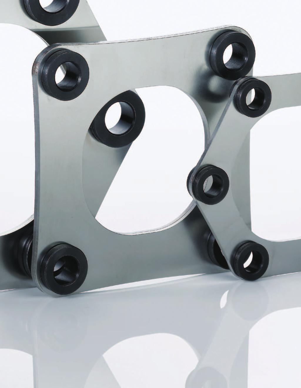
2 High-reliability Metal Plate Spring Format Realizing Its Best Shape Through Finite Element Analysis is an ultrahigh-rigidity flexible coupling derived from Miki Pulley's unique development capability. It has gained high reliability by its layered plate spring format as its best shape, which is rigid in the torsional direction and flexible in the bending asymmetrical and axial directions. is also available in a variety of models to cover a wide range of fields and purposes, and this full selection contributes to the higher precision and efficiency of instruments. S E R VO FLE X 4
3 5


 is applied for the plate spring shape and strength design of each model, which are important for the")
4 S E R V O F L E X High-reliability Metal Plate Spring Format When jointing a shaft to another shaft, it is extremely difficult to precisely center these two shafts. It is even more difficult to maintain the centering due to problems such as shaft deflection and shaft thermal expansion as a result of operating machine equipment, support block distortion after long hours of use, abrasion of the bearing, and for other reasons. The role of flexible couplings is not only simply to joint the driving shaft and driven shaft but also to resolve the above problems by selecting appropriate flexible couplings suitable for each purpose. Optimal Design by 3D-CAD and FEM An optimal design using the advanced finite element method (FEM) is applied for the plate spring shape and strength design of each model, which are important for the performance of the couplings, and thorough model analysis is performed by 3D-CAD. TORQUE THRUST BENDING RADIAL Ultrahigh-rigidity Metal Plate Spring Flexible Couplings A layered metal plate spring is adopted for the power transmission part of, enabling ideal performance of the flexible coupling, which is rigid in the torsional direction and flexible in the bending asymmetrical and axial directions. 2, Torsional rigidity [N m/rad] 15, 1, 5, SFS-SS SFC-SA2 SFC-DA2 Types of coupling Pin bush Oldham Cross-slit Heli-cal 6


5 FLEXIBLE COUPLINGS No Backlash The power transmission of is performed entirely by a friction lock, enabling no backlash, accurate shaft rotation, and ultraprecision control operation. Elastic (metal) coupling Metal plate spring: SERVOFLEX Elastic (rubber and resin) coupling Rubber, resin compression and resin plate spring, etc Corrected coupling Oldham, pin bush, etc. No Backlash Pseudo backlash Backlash Heat Rejection The stainless-steel plate spring reduces thermal conduction from a servo motor to the driven shaft, which also reduces variations in accuracy caused by thermal expansion. A B C A B C Temperature [ C] Time [min] 7


6 S E R V O F L E X Full Selection SFC MODEL ò Superbly strong high-strength aluminum alloy adopted ò Low inertia achieved by the shaft diameter interlock-type hub outer diameter ò No hazardous substances used, RoHS Directive compliant ò High-rigidity single element ò High-flexibility double element ò Taper shaft-compatible adapter ò Clamp mounting only with one bolt SFS MODEL ò Wide selection ò High-rigidity single element ò High-flexibility double element ò Floating shaft suitable for long shaft intervals ò Taper shaft-compatible hub ò Selectable from finished-assembly products and parts-delivered products ò Shaft bore design freely made from a pilot bore and a simple, strong friction lock 8

7 FULL LINEUP SFF SFM MODEL ò SFM for the machine tool main shaft, SFF for the feed shaft ò The main shaft-compatible type allows a maximum rotation speed of 2 min 1. ò High-precision mounting by using an excellent centering mechanism ò Irregularity removed to the extent possible and wind roar lowered during high-speed rotation ò High-rigidity single element ò High-flexibility double element SFH MODEL ò Ultrahigh torque transmission of 8 N m ò Unique plate spring shape in order to equally combine high torque transmission and flexibility ò High-rigidity single element ò High-flexibility floating shaft ò Shaft bore design freely made from a pilot bore 9


8 SFC MODEL SFC : A Wide Selection of Metal Plate Spring Couplings Made of High-power Aluminum Alloy Two types of couplings, either a rigid type with one element or a flexible type with two elements using a spacer, can be selected. The clamp method, an easy and exact installation method with no backlash, is adopted for the shaft installation method. Moreover, it is compatible with the taper shaft by using an adapter. It also complies with the EU Restriction of Hazardous Substances Directive, RoHS Directive that prohibits six hazardous substances such as mercury, lead, and others. PLATE SPRING OF IDEAL FORM High Rigidity, High Flexibility An ideal-shaped plate spring, designed based on thorough analysis using the advanced finite element method (FEM) is applied for the element. Two types of couplings, either a high-rigidity type with one element or a high-flexibility type with two elements using a spacer, can be selected. TORQUE THRUST BENDING RADIAL 1

9 A Wide Range of Installation Methods ò By adoption of the clamp method, installation is easy and exact. ò The servo motor taper shaft can be optionally supported. SFC SFC MODEL 11


10 SFC MODEL SFC High-strength aluminum alloy hub SFC Clamp lock High-rigidity single element High-flexibility double element SFC- SA2- B- B SFC- DA2- B- B + Taper shaft compatible High-rigidity single element SFC- SA2- B- BC High-flexibility double element SFC- DA2- B- BC Structure and Material SFC-SA2 Clamp bolt material: SCM435 Surface treatment: Solid lubricant film treatment SFC-DA2 Clamp bolt material: SCM435 Surface treatment: Solid lubricant film treatment Element material: Plate spring SUS34 Collar SUS34* 1 Element material: Plate spring SUS34 Collar SUS34* 1 Clamp hub material: High-strength aluminum alloy Surface treatment: Anodic coating film treatment Clamp hub material: High-strength aluminum alloy Surface treatment: Anodic coating film treatment Spacer material: High-strength aluminum alloy Surface treatment: Anodic coating film treatment Bolt material: SCM435 Surface treatment: Trivalent chromate treatment* 2 Bolt material: SCM435 Surface treatment: Trivalent chromate treatment * 2 SFC-SA2/DA-BC Clamp bolt material: SCM435 Surface treatment: Solid lubricant film treatment Element material: Plate spring SUS34 Collar SUS34 * The collar material of the items marked with *1 is S45C from size #8 to size #1, using trivalent chromium for the surface treatment. * The bolt surface treatment of the items marked with *2 is antirust coating from size #8 to size #1. Clamp hub material: High-strength aluminum alloy Surface treatment: Anodic coating film treatment Bolt material: SCM435 Surface treatment: Trivalent chromate treatment Taper adapter material: Equivalent of S45C Surface treatment: Black oxide finish 12


11 Wide Range of Installation Methods The clamp method is adopted for the method of mounting on the shaft, so it is easy to finish only by tightening the right and left sides. Power transmission is performed entirely by a friction lock. There is no backlash. A specialized jig is used for assembling couplings, so high-precision concentricity is ensured. It is also compatible with the servo motor taper shaft by installing a taper adapter. Taper adapter option SFC Ultralow Inertia The outer diameter of the clamp hub is designed so the outer diameter dimension interlocks with the bore diameter that customers adopt. By using a small bore diameter to shrink the outer diameter, it is possible to keep the inertia to the minimum required. One of three pattern shapes is determined automatically according to the combination of bore diameters to be adopted. TYPE A TYPE B TYPE C SFC MODEL 13
12 SFC MODEL SFC-SA2 SFC Specification Model Permissible tourque [N m] Max. permissible misalignment Parallel offset Angular misalignment [ ] Axial displacement Max. rotation speed [min 1 ] Torsional stiffness [N m/rad] Radial displacement [N/mm] Shape TYPE Moment of inertia SFC-5SA ± C SFC-1SA ± C SFC-2SA ± C A SFC-3SA ± B C SFC-35SA ± C A SFC-4SA ± B C A SFC-5SA ± B C A SFC-6SA ± B C SFC-8SA ± C SFC-9SA ± C SFC-1SA ± C * The indicated values in the moment of inertia and mass are measured with the maximum bore diameter. * The torsional stiffness indicates the actual measurement value of element. [kg m 2 ] Mass [kg] Price Dimensions TYPE A TYPE B TYPE C L L L S LF S LF S LF C C M M M d2 C K C A D N A1 D N D A2 D d2 d2 Model * 1 d2* 1 D N L LF S A1 A2 C K M Min. Max. Min. Max. Tightening torque [N m] SFC-5SA M2.4 to.5 C C5S2B1 SFC-1SA * M2.5* 3 1. to 1.1* 3 C C1S2B1 SFC-2SA M to 1.1 C C2S2B A C3S2B SFC-3SA2 5 1 Over M3 1.5 to 1.9 B C3S2B2 Over 1 14 Over C C3S2B3 SFC-35SA M4 3.4 to 4.1 C C35S2B A C4S2B SFC-4SA Over M4 3.4 to 4.1 B C4S2B2 Over Over C C4S2B A C5S2B1 38 SFC-5SA Over M5 7. to 8.5 B C5S2B2 Over Over C C5S2B A C6S2B1 46 SFC-6SA Over M6 14 to 15 B C6S2B2 Over 24 3 Over C C6S2B3 SFC-8SA M8 27 to 3 C C8S2B1 SFC-9SA M8 27 to 3 C C9S2B1 SFC-1SA M8 27 to 3 C C1S2B1 * *1 The torque permitted could be limited depending on the bore diameter. Refer to the Standard bore diameter on page15. * *2 indicates the value when or d2 is ø4 to ø7. It will be.6 if or d2 is ø8. * *3 indicates the value when or d2 is ø4 to ø7. It will be M2 if or d2 is ø8. The tightening torque of M2 is.4 to.5n m. +.1 * The dimensional tolerance of the target shaft is h7. However, for a shaft diameter of ø35, the tolerance is Contact us for tolerances other than h7. Shape TYPE Unit CAD file No. 14

13 Standard bore diameter Model SFC-5SA2 SFC-1SA2 Standard bore diameter d ò ò ò ò ò ò ò ò ò SFC-2SA2 1.2 ò ò ò ò ò ò ò SFC-3SA ò ò ò ò ò ò ò ò ò SFC-35SA2 ò ò ò ò ò ò ò ò ò SFC-4SA2 9 ò ò ò ò ò ò ò ò ò ò ò SFC-5SA2 22 ò ò ò ò ò ò ò ò ò ò ò ò SFC-6SA2 51 ò ò ò ò ò ò ò ò ò ò ò ò SFC-8SA2 ò ò ò ò ò ò ò ò SFC-9SA2 ò ò ò ò ò ò ò SFC-1SA2 ò ò ò ò ò * The bore diameters with value or marked ò are supported as standard bore diameter. * The permissible torque of small bore diameter indicated in the column with value is limited by the shaft locking mechanism. The value indicates its operating torque [N m]. * For bore diameters other than those above, processing cost is added to the standard price. SFC Optional: Taper shaft compatible Specification SFC- SA2- B- BC Model Moment of inertia [kg m 2 ] Shape TYPE B Shape TYPE C Shape TYPE B Mass [kg] Shape TYPE C Price SFC-5SA2- B-11BC SFC-5SA2- B-14BC SFC-5SA2- B-16BC SFC-6SA2- B-16BC Dimensions SFC- SA2- B- BC A1 L LC LF LA da DA D M A2 +.3 W +.3 T C A D Model CAD file No. Shape TYPE B Shape TYPE C SFC-5SA2- B-11BC C5S2C1 C5S2C2 SFC-5SA2- B-14BC C5S2C3 C5S2C4 SFC-5SA2- B-16BC C5S2C5 C5S2C6 SFC-6SA2- B-16BC C6S2C1 C6S2C2 TYPE B TYPE C C Taper 1/1 WA Model W T WA LA da DA L D LC LF C A1 A2 M SFC-5SA2- B-11BC B-14BC M5 - B-16BC SFC-6SA2- B-16BC M6 * The shape type is either TYPE B or TYPE C. Unit Ordering Information SFC SA2-14 B - 15 B Size Type: SA2 Single element, aluminum hub Bore diameter: -d2 B: Clamp hub BC: Taper adapter The latest CAD data can be downloaded from our website. ht tp://w w w.mikipulley.co.jp/ C A D The CAD mark indicates that CAD data is available by CD-ROM. The CAD file No. represents the file name in the CD-ROM. 15
14 SFC MODEL SFC-DA2 SFC Specification Model Permissible torque [N m] Max. permissible misalignment Parallel offset Angular misalignment [ ] Axial displacement Max. rotation speed [min 1 ] Torsional stiffness [N m/rad] Radial displacement [N/mm] Shape TYPE Moment of inertia [kg m 2 ] SFC-5DA (one side) ± C SFC-1DA (one side) ± C SFC-2DA (one side) ± C SFC-3DA (one side) ± Mass [kg] Price A B C SFC-35DA (one side) ± C SFC-4DA SFC-5DA SFC-6DA (one side) 1 (one side) 1 (one side) ± ± ± A B C A B C A B C SFC-8DA (one side) ± C SFC-9DA (one side) ± C SFC-1DA (one side) ± C * The indicated values in the moment of inertia and mass are measured with the maximum bore diameter. * The torsional stiffness indicates the actual measurement value of element. Dimensions TYPE A TYPE B TYPE C L L S LP S LF LP LF C C M M M L S LP LF C K C A D N A1 d3 D N d3 d2 D A2 d3 d2 D d2 Model * 1 d2* 1 D N L LF LP S A1 A2 C d3 K M Min. Max. Min. Max. Tightening torque [N m] Shape TYPE Unit CAD file No. SFC-5DA M2.4 to.5 C C5D2B1 SFC-1DA * M2.5* 3 1. to 1.1* 3 C C1D2B1 SFC-2DA M to 1.1 C C2D2B A C3D2B SFC-3DA2 5 1 Over M3 1.5 to 1.9 B C3D2B2 Over 1 14 Over C C3D2B3 SFC-35DA M4 3.4 to 4.1 C C35D2B A C4D2B SFC-4DA Over M4 3.4 to 4.1 B C4D2B2 Over Over C C4D2B A C5D2B1 38 SFC-5DA Over M5 7. to 8.5 B C5D2B2 Over Over C C5D2B A C6D2B1 46 SFC-6DA Over M6 14 to 15 B C6D2B2 Over 24 3 Over C C6D2B3 SFC-8DA M8 27 to 3 C C8D2B1 SFC-9DA M8 27 to 3 C C9D2B1 SFC-1DA M8 27 to 3 C C1D2B1 * *1 Permissible torque could be limited depending on the bore diameter. Refer to the Standard bore diameter on page 17. * *2 indicates the value when or d2 is ø4 to ø7. It will be 6. if or d2 is ø8. * *3 indicates the value when or d2 is ø4 to ø7. It will be M2 if or d2 is ø8. The tightening torque of M2 is.4 to.5n m. +.1 * The dimensional tolerance of the target shaft is h7. However, for a shaft diameter of ø35, the tolerance is Contact us for tolerances other than h7. 16

15 Standard bore diameter Model SFC-5DA2 SFC-1DA2 Standard bore diameter d ò ò ò ò ò ò ò ò ò SFC-2DA2 1.2 ò ò ò ò ò ò ò SFC-3DA ò ò ò ò ò ò ò ò ò SFC-35DA2 ò ò ò ò ò ò ò ò ò SFC-4DA2 9 ò ò ò ò ò ò ò ò ò ò ò SFC-5DA2 22 ò ò ò ò ò ò ò ò ò ò ò ò SFC-6DA2 51 ò ò ò ò ò ò ò ò ò ò ò ò SFC-8DA2 ò ò ò ò ò ò ò ò SFC-9DA2 ò ò ò ò ò ò ò SFC-1DA2 ò ò ò ò ò * The bore diameters with value or marked ò are supported as standard bore diameter. * The permissible torque of small bore diameter indicated in the column with value is limited by the shaft locking mechanism. The value indicates its operating torque [N m]. * For bore diameters other than those above, processing cost is added to the standard price. SFC Optional: Taper shaft compatible Specification SFC- DA2- B- BC Model Moment of inertia [kg m 2 ] Shape TYPE B Shape TYPE C Shape TYPE B Mass [kg] Shape TYPE C Price SFC-5DA2- B-11BC SFC-5DA2- B-14BC SFC-5DA2- B-16BC SFC-6DA2- B-16BC Dimensions A1 L LC LF LA Model CAD file No. Shape TYPE B Shape TYPE C SFC-5DA2- B-11BC C5D2C1 C5D2C2 SFC-5DA2- B-14BC C5D2C3 C5D2C4 SFC-5DA2- B-16BC C5D2C5 C5D2C6 SFC-6DA2- B-16BC C6D2C1 C6D2C2 A2 SFC- DA2- B- BC da DA D +.3 W +.3 T C A D TYPE B TYPE C C Taper 1/1 M WA Model W T WA LA da DA L D LC LF C A1 A2 M SFC-5DA2- B-11BC B-14BC M5 - B-16BC SFC-6DA2- B-16BC M6 * The shape type is either TYPE B or TYPE C. Unit Ordering Information SFC DA2-14 B - 15 B Size Type: DA2 Double element, aluminum hub Bore diameter: -d2 B: Clamp hub BC: Taper adapter The latest CAD data can be downloaded from our website. ht tp://w w w.mikipulley.co.jp/ C A D The CAD mark indicates that CAD data is available by CD-ROM. The CAD file No. represents the file name in the CD-ROM. 17
16 SFC MODEL Design Check Items SFC Spring characteristics ò Axial Load and Displacement Amount SFC- SA SA2 7 8SA2 9SA2 6 Load [N] SA2 1SA2 5SA2 3SA2 5SA2 2SA2 4SA2 6SA Displacement ò Axial Load and Displacement Amount SFC- DA DA2 7 8DA2 9DA2 6 Load [N] DA2 4DA2 6DA DA2 3DA2 5DA2 2DA2 5DA Displacement ò Parallel Offset Direction Load and Displacement Amount SFC- DA DA2 25 9DA2 Load [N] DA2 8DA DA2 4DA2 35DA2 5DA2 1DA2 5DA Parallel offset 18
17 Selection procedure (1) Calculate torque Ta applied to the coupling based on the motor output P and coupling operating rotation speed n. Ta [N m] = 955 Td = Ta K (see below) P [kw] n [min 1 ] (2) Calculate corrected torque Td applied to the coupling after deciding the service factor K based on load conditions. Load character Constant Fluctuations: Slight Fluctuations: Medium Fluctuations: Large In servo motor drive, multiply the service factor K=1.2 to 1.5 by the maximum torque of servo motor Ts. Td = Ts (1.2 to 1.5) (3) Select a coupling size with permissible torque Tn that becomes equal or greater than the corrected torque Td. Tn Td (4) Depending on the bore diameters, the coupling permissible torque may be limited. Refer to the Specification and Standard bore diameter. (5) Confirm if the required shaft diameter does not exceed the maximum bore diameter of the selected size. For machines whose load torques periodically fluctuate drastically, contact us. SFC Simplified selection The table indicates suitable sizes based on the rated output, rated torque and maximum torque of general-purpose servo motors. Since torque characteristics of servo motors differ depending on the manufacturer, select the coupling size after confirming the specification of the manufacturer. Servo motor specification Compatible coupling specification Rated output [kw] Rated revolution [min 1 ] Rated torque [N m] Max. torque [N m] Shaft dia. Single element Double element Max. bore Model (SFC- SA2) Model (SFC- DA2) dia SA2 1DA SA2 2DA SA2 3DA SA2 35DA SA2 5DA SA2 5DA SA2 5DA SA2 4DA SA2 6DA SA2 5DA SA2 5DA SA2 8DA SA2 6DA SA2 5DA SA2 8DA SA2 5DA SA2 9DA SA2 8DA SA2 6DA SA2 8DA SA2 6DA SA2 9DA2 35 The latest CAD data can be downloaded from our website. ht tp://w w w.mikipulley.co.jp/ C A D The CAD mark indicates that CAD data is available by CD-ROM. The CAD file No. represents the file name in the CD-ROM. 19
18 SFC MODEL Design Check Items SFC Feed-screw systems (1) Oscillation phenomena of servo motors If the eigenfrequency of the entire feed-screw system is under 4 to 5Hz, oscillation may occur depending on the gain adjustment of the servo motor. The problems can be avoided by raising the eigenfrequency of the mechanical system or adjusting the tuning function (filter function) of the servo motor. Contact us for unclear points concerning oscillation phenomena of servo motors. (2) Resonance caused by stepping motors Resonance can occur within a certain speed range due to the pulsation frequency of the stepping motor and the eigenfrequency of the entire system. Resonance can be avoided by not applying the resonant rotation speed, or by reviewing the eigenfrequency in the design phase. Contact us for unclear points concerning resonance of stepping motors. How to evaluate the eigenfrequency of feed-screw system Mounting The concentricity of the right and left bore diameters is ensured by adjusting with an specialized jig. However, the assembly accuracy may be disturbed if a strong impact is given to the product. Please handle it with care. (1) Confirm the clamping bolts are loosened. Remove the rust, dust and oil content on the inside diameter surface of the shaft and coupling. (Wipe off the oil content completely with a waste cloth, etc.) (2) Insert the coupling into the shaft. At this time, do not apply more than necessary force such as compression or pulling to the element part of the coupling. After the coupling is mounted into the motor, do not apply excessive compression when inserting the coupling into the mating shaft. (3) Confirm the two clamping bolts are loosened and the coupling is movable to the axial and rotative directions. If it does not move smoothly, adjust centering of both shafts again. If the concentricity can not be confirmed with the method described above, confirm the mounting accuracy by other measures. Axial direction (1) Select the coupling according to the normal operating torque and maximum torque of the servo motor/stepping motor. (2) In the following feed-screw system, evaluate the entire eigenfrequency: Nf from the torsional stiffness: k of the coupling and feed screw, the moment of inertia: J1 of the driving side and the moment of inertia: J2 of the driven side. Rotative direction Motor Coupling Feed screw Table (4) Make sure that the insertion length of the coupling into the shaft is kept in the position so that the target shaft is in contact with the entire length of the flange (LF dimension) as illustrated below. Bearing LF LF Nf: Eigenfrequency of the entire feed-screw system [Hz] k: Torsional stiffness of the coupling and feed screw [N m/rad] J1: Moment of inertia of the driving side J2: Moment of inertia of the driven side J1 J2 Size LF dimension
19 (5) As a principle, the target shaft is a circular shaft. However, if shafts other than a circular shaft have to be used for a certain reason, be careful with the shaft installation position as illustrated below. (Note that key slot, D-cut, etc. must not be processed on the filling side of the part.) Certain shaft installation positioning may result in damage to the coupling itself and lowering of shaft-retaining force. It is recommended to use a circular shaft for fully satisfactory coupling performance. Coupling bore diameter surface treatment For the SFC model, depending on the process, although there are two types of parts, one with bore diameter surface treatment such as additional processing and key slot processing and the other without surface treatment, there is no problem in terms of performance of the couplings. Contact us for advice regarding whether bore diameter surface treatment should be used according to the customers conditions of use. SFC ò Example of Good Mounting ò Example of Bad Mounting (6) After checking that no force such as compression, tension, etc. is applied to the axial direction, the shaft is retained so that the whole length of the clamp hub is in contact with both shafts, and two clamp bolts are tightened at an appropriate torque value. To tighten the clamp bolts, a calibrated torque wrench is used within the range of the clamp bolt-tightening torque as shown in the table below. Size Clamp bolt Tightening torque [N m] 5 M2 (.4 to.5) 1 M2 (.4 to.5) 1 M2.5 (1. to 1.1) 2 M2.5 (1. to 1.1) 3 M3 (1.5 to 1.9) 35 M4 (3.4 to 4.1) 4 M4 (3.4 to 4.1) 5 M5 (7. to 8.5) 6 M6 (14 to 15) 8 M8 (27 to 3) 9 M8 (27 to 3) 1 M8 (27 to 3) * If the bore diameter is ø8, size 1 will be M2. * For the above tightening torque, solid lubricant film treatment is applied to the bolt and the torque coefficient is.18. * The value of the tightening torque is between the minimum and the maximum values. The bolts should be tightened by the tightening torque within this range. ò Solid lubricant film treatment is applied to the clamp bolt, so make sure that Miki Pulley s specified clamp bolt is used and no coatings such as oil, etc. are applied. If any coating is applied to the surface, the clamp bolt, the coupling itself, and other parts might be damaged due to excessive shaft force. The latest CAD data can be downloaded from our website. ht tp://w w w.mikipulley.co.jp/ C A D The CAD mark indicates that CAD data is available by CD-ROM. The CAD file No. represents the file name in the CD-ROM. 21


20 SFS MODEL : A Wide Selection of Metal Plate Spring Couplings Made of Steel SFS Three types of couplings, either a high-rigidity type with one element, a high-flexibility type with two elements using a spacer, or a floating shaft with configurable spacer length can be selected. A variety of methods are available for mounting on a shaft such as a friction lock compatible with a large diameter, a highprecision friction lock, a taper shaft-compatible method, and others. The pilot bore item has also been standardized, enabling methods such as the key/set screw method, shrink fit-compatible method, and others. PLATE SPRING OF IDEAL FORM High Rigidity, High Flexibility An ideal-shaped plate spring, designed based on thorough analysis using the advanced finite element method (FEM), is applied for the element. Three types of couplings, either a high-rigidity type with one element, a high-flexibility type with two elements using a spacer, or a floating shaft with configurable spacer length can be selected. TORQUE THRUST BENDING RADIAL 22

21 Available to Assemble in Parts ò The product can be delivered in parts, so that this can be used even for designs where parts cannot be mounted on the finished item. S, W, and G types ò A finished-assembly product is also available as a standard. SS and DS types SFS SFS MODEL 23

22 SFS MODEL General-purpose steel hub SFS Pilot bore High-rigidity single element SFS- S High-flexibility double element SFS- W Double-element floating shaft SFS- G SFS Key/set screw item High-rigidity single element High-flexibility double element Double-element floating shaft SFS- S- H- H SFS- W- H- H SFS- G- H- H High-precision friction lock High-rigidity single element SFS- S- M- M High-flexibility double element SFS- W- M- M Double-element floating shaft SFS- G- M- M + Taper shaft supporting High-rigidity single element SFS- S- M- C High-flexibility double element SFS- W- M- C Double-element floating shaft SFS- G- M- C Large-diameter friction lock High-rigidity single element SFS- SS- K- K High-flexibility double element SFS- DS- K- K Structure and Material SFS-S Element material: Plate spring SUS34 Collar Equivalent of S45C Flange hub material: Equivalent of S45C Surface treatment: Black oxide finish Reamer bolt material: SCM435 Surface treatment: Black oxide finish SFS-W Spacer material: Equivalent of S45C Surface treatment: Black oxide finish Flange hub material: Equivalent of S45C Surface treatment: Black oxide finish Element material: Plate spring SUS34 Collar Equivalent of S45C Reamer bolt material: SCM435 Surface treatment: Black oxide finish SFS-SS Hexagon socket head cap screw: Equivalent of SCM435 Surface treatment: Black oxide finish Element material: Plate spring SUS34 Collar Equivalent of S45C Sleeve material: Equivalent of S45C Surface treatment: Black oxide finish Flange material: Equivalent of S45C Surface material: Black oxide finish Pressure bolt material: SCM435 Surface material: Black oxide finish SFS-DS Spacer material: Equivalent of S45C Surface treatment: Black oxide finish Element material: Plate spring SUS34 Collar Equivalent of S45C Sleeve material: Equivalent of S45C Surface treatment: Black oxide finish Flange material: Equivalent of S45C Surface treatment: Black oxide finish Pressure bolt material: SCM435 Surface treatment: Black oxide finish SFS-G SFS-S-M-M SFS-S-M-C Element material: Plate spring SUS34 Collar Equivalent of S45C Pressure bolt material: SCM435 Surface treatment: Black oxide finish Reamer bolt material: SCM435 Surface treatment: Black oxide finish Spacer material: Carbon steel Surface treatment: Black oxide finish or coating Reamer bolt material: SCM435 Surface treatment: Black oxide finish Flange material: Equivalent of S45C Surface treatment: Black oxide finish Flange material: Equivalent of S45C Surface treatment: Black oxide treatment Flange hub material: Equivalent of S45C Surface treatment: Black oxide finish Reamer bolt material: SCM435 Surface treatment: Black oxide finish Element material: Plate spring SUS34 Collar Equivalent of S45C Sleeve material: Equivalent of S45C Surface treatment: Black oxide finish Element material: Plate spring SUS34 Collar Equivalent of S45C 24


23 Installing the Shaft on the Coupling A variety of methods are available for mounting on a shaft such as the friction lock compatible with a large diameter, a high-precision friction lock, a taper shaftcompatible method, and others. The pilot bore item has also been standardized, enabling designs freely by customers such as the key/set screw method, shrink fit-compatible method, and others. High-Precision Friction Lock Type + High-Precision Friction Lock Type SFS- S- M- M High-Precision Friction Lock Type + Taper Shaft Type SFS- S- M- C Pilot Bore Type Bore processing can be performed freely because the product is provided only with a drilled hole. Key/Set Screw Type This is a finished product using key slot processing, bore processing, and set screw processing based on Miki Pulley s standard bore processing specifications. The parts can be assembled immediately after delivery to the customer. Target model: SFS- S, SFS- W, SFS- G * Indicate the nominal bore diameter (blank, H, N) after the model. E.g.) SFS- S- H- N High-Precision Friction Lock Type A double-taper lock part is allocated to the coupling, so high-precision installation is achieved by high locking force and rigidity with the shaft. Target model: SFS- S, SFS- W, SFS- G * Indicate the nominal bore diameter (M) after the model. E.g.) SFS- S- M- M SFS Large-Diameter Shaft- Supporting Friction Lock Type + Large-Diameter Shaft- Supporting Friction Lock Type SFS- SS- K- K Taper Shaft Type Direct installation on the servo motor taper shaft is achieved. Target model: SFS- S, SFS- W, SFS- G * Indicate the nominal bore diameter (C) after the model. E.g.) SFS- S- M- C Large Diameter-Supporting Friction Lock Type Locking force is high as a result of the single-taper lock method. Shafts larger than the size of the coupling are also compatible. Target model: SFS- SS, SFS- DS * Indicate the nominal bore diameter (K) after the model. E.g.) SFS- SS- K- K S F S M O D E L 25
24 SFS MODEL SFS-S Specification SFS Model Permissible torque [N m] Max. permissible misalignment Angular misalignment [ ] Axial displacement Max. rotation speed [min -1 ] Torsional stiffness [N m/rad] Radial displacement [N/mm] Moment of inertia [kg m2] SFS-5S 2 1 ± SFS-6S 4 1 ± SFS-6S- M- M 4 1 ± SFS-6S- M-11C 4 1 ± SFS-6S- M-16C 4 1 ± SFS-8S 8 1 ± SFS-8S- M- M 8 1 ± SFS-8S- M-16C 8 1 ± SFS-9S 18 1 ± SFS-9S- M- M 18 1 ± SFS-9S- M-16C 18 1 ± SFS-1S 25 1 ± SFS-1S- M- M 25 1 ± SFS-12S 45 1 ± SFS-12S- M- M 45 1 ± SFS-14S 8 1 ± SFS-14S-35M-35M 58 1 ± * The indicated values in the moment of inertia and mass are measured with the maximum bore diameter. * The price of SFS- S is applied to the case of the pilot bore. Mass [kg] Price Dimensions SFS- S S L LF F C A D K D N dv Reamer bolt M Model d2 Pilot bore Min. Max. * For additional processing, refer to the "Standard bore processing specification" on page 32. * Pilot bores are drilled bores. D N L LF S F K M CAD file No. SFS-5S M5 22 SFS-S1 SFS-6S M6 25 SFS-S2 SFS-8S M6 29 SFS-S3 SFS-9S M8 36 SFS-S4 SFS-1S M8 36 SFS-S5 SFS-12S M1 45 SFS-S6 SFS-14S M12 54 SFS-S7 Unit Ordering Information SFS - 1 S - 25 H - 3 H Size Type: S Single element Bore diameter: - d2 with standard bore processing Blank: Previous edition JIS (Class 2) compliant H: New JIS compliant N: New standard motor compatible * Blank if bore processing is not required 26

25 Dimensions SFS- S- M- M C A D Screw bore for dismounting M2 C M1 D N1 LF1 S L LF2 C M1 d2 N2 Reamer bolt M K Screw bore for dismounting M2 Model SFS-6S SFS-8S SFS-9S SFS-1S SFS-12S SFS-14S CAD file No. 12M 14M 15M SFS-M11 SFS-M12 SFS-M13 15M 16M 2M 22M SFS-M14 SFS-M15 SFS-M16 SFS-M17 25M 28M 35M SFS-M18 SFS-M19 SFS-M11 25M 28M 3M 35M SFS-M21 SFS-M22 SFS-M23 SFS-M24 3M 35M SFS-M25 SFS-M26 35M SFS-M27 * CAD data is provided for one flange for each bore diameter. Use the data in combination. SFS Unit Model Bore dia. d2 D N1 N2 L LF1 LF2 S C K M M1 M2 SFS-6S M- M M M5 2-M5 SFS-8S M- M M M6 2-M6 SFS-9S M- M M-35M M M6 2-M6 SFS-1S M- M M M6 2-M6 SFS-12S M- M* M M8 2-M8 SFS-14S 35M-35M M M8 2-M8 * *1 The permissible torque of SFS-12S-3M- M is limited by the shaft locking mechanism of ø3 and will be 38N m. +.1 * The dimensional tolerance of the target shaft is h7. However, for a shaft diameter of ø35, the tolerance is Ordering Information Dimensions SFS - 1 S - 25 M - 3 M Size SFS- S- M- C Type: S Single element Bore diameter: - d2 M: Friction locking Screw bore for dismounting M2 C M1 D N1 LF1 L LF2 S J d4 N2 Taper 1/1 K C A D W T Model SFS-6S SFS-8S SFS-9S CAD file No. 12M 14M 15M 11C 16C SFS-M11 SFS-M12 SFS-M13 SFS-C1 SFS-C2 15M 16M 2M 22M 16C SFS-M14 SFS-M15 SFS-M16 SFS-M17 SFS-C3 25M 28M 16C SFS-M18 SFS-M19 SFS-C4 * CAD data is provided for one flange for each bore diameter. Use the data in combination. Reamer bolt M d2 Unit Model Bore dia. d2 Ordering Information W +.3 SFS - 8 S - 2 M - 16 C Size T +.3 d4 J D N1 N2 L LF1 LF2 S C K M M1 M2 SFS-6S M-11C M-16C M M5 2-M5 SFS-8S M-16C M M6 2-M6 SFS-9S M-16C M M6 2-M6 * The dimensional tolerance of the target shaft of the friction lock-side hub is h7. Type: S Single element Bore diameter: - d2 M: Friction locking C: Taper shaft compatible The latest CAD data can be downloaded from our website. ht tp://w w w.mikipulley.co.jp/ C A D The CAD mark indicates that CAD data is available by CD-ROM. The CAD file No. represents the file name in the CD-ROM. 27
26 SFS MODEL SFS-W Specification SFS Model Permissible torque [N m] Max. permissible misalignment Parallel offset Angular misalignment [ ] Axial displacement Max. rotation speed [min -1 ] Torsional stiffness [N m/rad] Radial displacement [N/mm] Moment of inertia [kg m 2 ] SFS-5W (one side) ± SFS-6W (one side) ± SFS-6W- M- M (one side) ± SFS-6W- M-11C (one side) ± SFS-6W- M-16C (one side) ± SFS-8W (one side) ± SFS-8W- M- M (one side) ± SFS-8W- M-16C (one side) ± SFS-9W (one side) ± SFS-9W- M- M (one side) ± SFS-9W- M-16C (one side) ± SFS-1W (one side) ± SFS-1W- M- M (one side) ± SFS-12W (one side) ± SFS-12W- M- M (one side) ± SFS-14W (one side) ± SFS-14W-35M-35M (one side) ± * The indicated values in the moment of inertia and mass are measured with the maximum bore diameter. * The price of SFS- W is applied to the case of the pilot bore. Mass [kg] Price Dimensions SFS- W LP L S LF F C A D K dv D N d3 Reamer bolt M Model d2 Pilot bore Min. Max. * For additional processing, refer to the Standard bore processing specification on page 32. * Prepared bores are drilled bores. D N L LF LP S F d3 K M CAD file No. SFS-5W M5 15 SFS-W1 SFS-6W M6 18 SFS-W2 SFS-8W M6 2 SFS-W3 SFS-9W M8 27 SFS-W4 SFS-1W M8 27 SFS-W5 SFS-12W M1 32 SFS-W6 SFS-14W M12 38 SFS-W7 Unit Ordering Information SFS - 1 W - 25 H - 3 H Size Type: W Double element Bore diameter: - d2 with standard bore processing Blank: Previous edition JIS (Class 2) compliant H: New JIS compliant N: New standard motor compatible * Blank if bore processing is not required 28

27 Dimensions SFS- W- M- M C A D Screw bore for dismounting M2 D N1 M1 C LF1 L S LP S d3 LF2 C d2 N2 K M1 Reamer bolt M Screw bore for dismounting M2 Model SFS-6W SFS-8W SFS-9W SFS-1W SFS-12W SFS-14W CAD file No. Spacer 12M 14M 15M SFS-W8 SFS-M11 SFS-M12 SFS-M13 Spacer 15M 16M 2M 22M SFS-W9 SFS-M14 SFS-M15 SFS-M16 SFS-M17 Spacer 25M 28M 35M SFS-W1 SFS-M18 SFS-M19 SFS-M11 Spacer 25M 28M 3M 35M SFS-W11 SFS-M21 SFS-M22 SFS-M23 SFS-M24 Spacer 3M 35M SFS-W12 SFS-M25 SFS-M26 Spacer 35M SFS-W13 SFS-M27 * CAD data is provided for one flange for each bore diameter. Use the data in combination. SFS Unit Model Bore dia. d2 D N1 N2 L LF1 LF2 LP S C d3 K M M1 M2 SFS-6W M- M M M5 2-M5 SFS-8W M- M M6 2 4-M6 2-M6 SFS-9W M- M M-35M M M6 2-M6 SFS-1W M- M M M6 2-M6 SFS-12W M- M* M M8 2-M8 SFS-14W 35M-35M M M8 2-M8 * *1 The permissible torque of SFS-12W-3M- M is limited by the shaft fixing mechanism of ø3 and will be 38N m. +.1 * The dimensional tolerance of the target shaft is h7. However, for a shaft diameter of ø35, the tolerance is Ordering Information Dimensions SFS - 1 W - 25 M - 3 M Size SFS- W- M- C Type: W Double element Bore diameter: - d2 M: Friction locking Screw bore for dismounting M2 D N1 C LF1 L S LP S d3 LF2 J d4 N2 d2 Taper 1/1 K T C A D W Model CAD file No. SFS-6W Spacer 12M 14M 15M 11C 16C SFS-W8 SFS-M11 SFS-M12 SFS-M13 SFS-C1 SFS-C2 SFS-8W Spacer 15M 16M 2M 22M 16C SFS-W9 SFS-M14 SFS-M15 SFS-M16 SFS-M17 SFS-C3 SFS-9W Spacer 25M 28M 16C SFS-W1 SFS-M18 SFS-M19 SFS-C4 * CAD data is provided for one flange for each bore diameter. Use the data in combination. M1 Reamer bolt M Unit Model Bore dia. d2 W +.3 T +.3 d4 J D N1 N2 L LF1 LF2 LP S C d3 K M M1 M2 SFS-6W M-11C M-16C M M5 2-M5 SFS-8W M-16C M6 2 4-M6 2-M6 SFS-9W M-16C M M6 2-M6 * The dimensional tolerance of the target shaft of the friction lock-side hub is h7. Ordering Information SFS - 8 W - 2 M - 16 C Size Type: W Double element Bore diameter: - d2 M: Friction locking C: Taper shaft compatible The latest CAD data can be downloaded from our website. ht tp://w w w.mikipulley.co.jp/ C A D The CAD mark indicates that CAD data is available by CD-ROM. The CAD file No. represents the file name in the CD-ROM. 29
28 SFS MODEL SFS-G Specification SFS Model Permissible torque [N m] Max. permissible misalignment Parallel offset Angular misalignment [ ] Axial displacement Max. rotation speed [min -1 ] Torsional stiffness [N m/rad] Radial displacement [N/mm] Moment of inertia [kg m 2 ] SFS-5G (one side) ± SFS-6G (one side) ± SFS-6G- M- M (one side) ± SFS-6G- M-11C (one side) ± SFS-6G- M-16C (one side) ± SFS-8G (one side) ± SFS-8G- M- M (one side) ± SFS-8G- M-16C (one side) ± SFS-9G (one side) ± SFS-9G- M- M (one side) ± SFS-9G- M-16C (one side) ± SFS-1G (one side) ± SFS-1G- M- M (one side) ± SFS-12G (one side) ± SFS-12G- M- M (one side) ± SFS-14G (one side) ± SFS-14G-35M-35M (one side) ± * The indicated values in the moment of inertia and mass are measured with the maximum bore diameter. * The price of SFS- G is applied to the case of the pilot bore. Mass [kg] Price Dimensions SFS- G L LS S LF F C A D K D N d2 Reamer bolt M Model d2 Pilot bore Min. Max. D N L LF LS S F K M CAD file No. SFS-5G M5 22 SFS-G1 SFS-6G M6 25 SFS-G2 SFS-8G M6 29 SFS-G3 SFS-9G M8 36 SFS-G4 SFS-1G M8 36 SFS-G5 SFS-12G M1 45 SFS-G6 SFS-14G M12 54 SFS-G7 * Specify the required LS dimensions when requesting products other than the above LS dimensions. Contact us if the LS is equal or greater than 1. * Pilot bores are drilled bores. For additional processing, refer to the "Standard bore processing specification" on page 32. Unit Ordering Information SFS - 1 G - 25 H - 3 H Size Type: G Double element Floating shaft LS=5 Length of spacer * Blank if standard spacer Bore diameter: - d2 with standard bore processing Blank: Previous edition JIS (Class 2) compliant H: New JIS compliant N: New standard motor compatible * Blank if bore processing is not required 3

29 Dimensions SFS- G- M- M C A D Screw bore for dismounting M2 D N1 C LF1 S LS S LF2 M1 L C d2 N2 M1 Reamer bolt M K Screw bore for dismounting M2 Model SFS-6G SFS-8G SFS-9G SFS-1G SFS-12G SFS-14G CAD file No. Spacer 12M 14M 15M SFS-G8 SFS-M11 SFS-M12 SFS-M13 Spacer 15M 16M 2M 22M SFS-G9 SFS-M14 SFS-M15 SFS-M16 SFS-M17 Spacer 25M 28M 35M SFS-G1 SFS-M18 SFS-M19 SFS-M11 Spacer 25M 28M 3M 35M SFS-G11 SFS-M21 SFS-M22 SFS-M23 SFS-M24 Spacer 3M 35M SFS-G12 SFS-M25 SFS-M26 Spacer 35M SFS-G13 SFS-M27 * CAD data is provided for one flange for each bore diameter. Use the data in combination. SFS Unit Model Bore dia. d2 D N1 N2 L LF1 LF2 LS S C K M M1 M2 SFS-6G M- M M M5 2-M5 SFS-8G M- M M6 2 4-M6 2-M6 SFS-9G M- M M-35M M M6 2-M6 SFS-1G M- M M M6 2-M6 SFS-12G M- M* M M8 2-M8 SFS-14G 35M-35M M M8 2-M8 * *1 The permissible torque of SFS-12G-3M- M is limited by the shaft locking mechanism of ø3 and will be 38N m. +.1 * The dimensional tolerance of the target shaft is h7. However, for a shaft diameter of ø35, the tolerance is * Specify the required LS dimensions when requesting products other than the above LS dimensions. Contact us if the LS is equal or greater than 1. Ordering Information SFS - 1 G - 25 M - 6 M Size Type: G Double element, Floating shaft LS=5 Bore diameter: - d2 M: Friction locking Length of spacer * Blank if standard spacer Dimensions SFS- G- M- C Screw bore for dismounting M2 D N1 C LF1 S LS S L LF2 d4 N2 d2 Taper 1/1 K T C A D W Model SFS-6G SFS-8G SFS-9G CAD file No. Spacer 12M 14M 15M 11C 16C SFS-G8 SFS-M11 SFS-M12 SFS-M13 SFS-C1 SFS-C2 Spacer 15M 16M 2M 22M 16C SFS-G9 SFS-M14 SFS-M15 SFS-M16 SFS-M17 SFS-C3 Spacer 25M 28M 16C SFS-G1 SFS-M18 SFS-M19 SFS-C4 * CAD data is provided for one flange for each bore diameter. Use the data in combination. M1 Reamer bolt M Unit Model Bore dia. d2 W +.3 T +.3 d4 J D N1 N2 L LF1 LF2 LS S C K M M1 M2 SFS-6G M-11C M-16C M M5 2-M5 SFS-8G M-16C M6 2 4-M6 2-M6 SFS-9G M-16C M M6 2-M6 * The dimensional tolerance of the target shaft of the friction lock-side hub is h7. * Specify the required LS dimensions when requiring products other than the above LS dimensions. (Ex: SFS-1G LS=5) Contact us if the LS is greater than or equal to 1. Ordering Information SFS - 8 G - 2 M - 16 C Size Type: G Double element, Floating shaft LS=5 Length of spacer * Blank if standard spacer Bore diameter: - d2 M: Friction locking C: Taper shaft compatible The latest CAD data can be downloaded from our website. ht tp://w w w.mikipulley.co.jp/ C A D The CAD mark indicates that CAD data is available by CD-ROM. The CAD file No. represents the file name in the CD-ROM. 31
30 SFS MODEL Standard Bore Processing Specification Dimensions SFS Bore processing is available upon request. Products are stored with pilot bores. Bores are machined based on the following specification. Assign as described below when ordering. E.g.) SFS-1W 32H-38H The positions of set screws will not be on the same plane. For the standardized sizes other than described below, refer to the technical data at the end of the catalog. SFS-S T1 W1 M M W2 T2 d2 SFS-W T2 d2 SFS-G M W2 T2 W1 T1 M M d2 W1 W2 M T1 Unit Previous edition JIS (Class 2) compliant New JIS compliant New standard motor compatible Nominal bore dia. Bore diameter (-d2) Key slot width (W1 W2) Key slot height (T1 T2) Set screw bore (M) Nominal bore dia. Bore diameter (-d2) Key slot width (W1 W2) Key slot height (T1 T2) Set screw bore (M) Nominal bore dia. Bore diameter (-d2) Key slot width (W1 W2) Key slot height (T1 T2) Set screw bore (M) Tolerance H7, H8 E9 +.3 Tolerance H7 H9 +.3 Tolerance G7,F7 H M M M M M4 12H M M4 14H M4 14N * Below ø11 of New JIS compliant and below ø11 of New standard motor compatible have the same contents as Previous JIS compatible (Class 2) M M4 15H M M4 16H M M4 17H M M4 18H M M4 19H M5 19N M M4 2H M M6 22H M M6 24H M6 24N M M6 25H M M6 28H M6 28N M M6 3H M M8 32H M M8 35H M M8 38H M8 38N M M8 4H M M8 42H M8 42N M M8 45H M M8 48H M1 48N M M8 5H M M1 55H M1 55N M M1 56H M M1 6H M1 6N M1 Distance from the edge surface of set screw Size Distance
31 Centering and finishing in flange bore drilling If customers are planning to apply bore diameter processing using pilot bore items by themselves, the instructions below should be followed: ò Centering ò SHPANNRING specification According to Figure A, check the center run-out of each size by the flange hub outer diameter. Adjust the chuck to achieve the following accuracy and finish the inner diameter. d.2.2 Finish as illustrated in Figure B when processing to apply the locking method according to SPANNRING. 6.3 E SFS Chuck Flange 1.6 C.5 C.5 C R Combination of standard bore diameter Details of the E portion A type using a friction lock for mounting on the shaft The combinations of the standard bore diameter of (SFS- S/W/ G- M- M) are as follows: SFS-6 Standard bore diameter Standard bore diameter d2 12M 14M 15M 16M 2M 22M 25M 28M 3M 35M 12M ò ò ò 14M ò ò 15M ò SFS-8 Standard bore diameter Standard bore diameter d2 12M 14M 15M 16M 2M 22M 25M 28M 3M 35M 15M ò ò ò ò 16M ò ò ò 2M ò ò 22M ò SFS-9 Standard bore diameter Standard bore diameter d2 12M 14M 15M 16M 2M 22M 25M 28M 3M 35M 25M ò ò ò 28M ò ò SFS-1 Standard bore diameter Standard bore diameter d2 12M 14M 15M 16M 2M 22M 25M 28M 3M 35M 25M ò ò ò ò 28M ò ò ò 3M ò ò 35M ò SFS-12 Standard bore diameter Standard bore diameter d2 12M 14M 15M 16M 2M 22M 25M 28M 3M 35M 3M M ò SFS-14 Standard bore diameter d2 12M 14M 15M 16M 2M 22M 25M 28M 3M 35M Standard bore diameter 35M ò * The bore diameters with value or marked ò are supported as standard bore diameter. * The permissible torque of small bore diameter indicated in the column with value is limited by the shaft locking mechanism. The value indicates its operating torque [N m]. The latest CAD data can be downloaded from our website. ht tp://w w w.mikipulley.co.jp/ C A D The CAD mark indicates that CAD data is available by CD-ROM. The CAD file No. represents the file name in the CD-ROM. 33
32 SFS MODEL SFS-SS Specification SFS Model Permissible torque [N m] Max. permissible misalignment Parallel offset Angular misalignment [ ] Axial displacement Max. rotation speed [min -1 ] * The indicated values in the moment of inertia and mass are measured with the maximum bore diameter. Torsional stiffness [N m/rad] Radial displacement [N/mm] Moment of inertia [kg m 2 ] SFS-8SS ± SFS-9SS ± SFS-1SS ± SFS-12SS ± SFS-14SS ± Mass [kg] Price Dimensions L S LF C K M C A D D N1 d2 N2 Pressure bolt M1 Screw bore for dismounting M2 H Unit Model D L d2 N1 N2 LF S C K H M M1 M2 SFS-8SS SFS-9SS SFS-1SS SFS-12SS SFS-14SS drill M8 4-M6 2-M drill M8 4-M6 2-M drill M8 4-M6 2-M drill M1 4-M6 2-M M M drill M12 4-M8 2-M M M8 * The combination of and d2 is not available if both bore diameters are equal or greater than the dimension K. Refer to the Combination of standard bore diameters. +.1 * The dimensional tolerance of the target shaft is h7. However, for a shaft diameter of ø35, the tolerance is Model SFS-8SS SFS-9SS SFS-1SS SFS-12SS SFS-14SS CAD file No. ø22 ø25 ø28 ø3 ø32 ø35 SFS-SS1 SFS-SS2 SFS-SS3 SFS-SS4 SFS-SS5 SFS-SS6 ø32 ø35 ø38 ø4 ø42 ø45 ø48 SFS-SS7 SFS-SS8 SFS-SS9 SFS-SS1 SFS-SS11 SFS-SS12 SFS-SS13 ø35 ø38 ø4 ø42 ø45 ø48 ø5 ø52 ø55 ø6 SFS-SS14 SFS-SS15 SFS-SS16 SFS-SS17 SFS-SS18 SFS-SS19 SFS-SS2 SFS-SS21 SFS-SS22 SFS-SS23 ø38 ø4 ø42 ø45 ø48 ø5 ø52 ø55 ø6 ø62 ø65 ø7 SFS-SS24 SFS-SS25 SFS-SS26 SFS-SS27 SFS-SS28 SFS-SS29 SFS-SS3 SFS-SS31 SFS-SS32 SFS-SS33 SFS-SS34 SFS-SS35 ø45 ø48 ø5 ø52 ø55 ø6 ø62 ø65 ø7 ø75 ø8 SFS-SS36 SFS-SS37 SFS-SS38 SFS-SS39 SFS-SS4 SFS-SS41 SFS-SS42 SFS-SS43 SFS-SS44 SFS-SS45 SFS-SS46 * CAD data is provided for one flange for each bore diameter. Use the data in combination. 34

33 Combination of standard bore diameter SFS-8SS Standard bore diameter Standard bore diameter d ò ò ò ò ò ò 25 ò ò ò ò ò 28 ò ò ò ò 3 ò ò ò 32 ò ò 35 ò SFS SFS-9SS Standard bore diameter Standard bore diameter d ò ò ò ò ò ò ò 35 ò ò ò ò ò ò 38 ò ò ò ò ò 4 ò ò ò ò SFS-1SS Standard bore diameter Standard bore diameter d ò ò ò ò ò ò ò ò ò ò 38 ò ò ò ò ò ò ò ò ò 4 ò ò ò ò ò ò ò ò 42 ò ò ò ò ò ò ò 45 ò ò ò ò ò ò SFS-12SS Standard bore diameter Standard bore diameter d SFS-14SS Standard bore diameter Standard bore diameter d ò ò ò ò ò ò ò ò ò ò ò 48 ò ò ò ò ò ò ò ò ò ò 5 ò ò ò ò ò ò ò ò ò 52 ò ò ò ò ò ò ò ò 55 ò ò ò ò ò ò ò 6 ò ò ò ò ò ò * The bore diameters with value or marked ò are supported as standard bore diameter. * The permissible torque of small bore diameter indicated in the column with value is limited by the shaft locking mechanism. The value indicates its operating torque [N m]. Ordering Information SFS - 8 SS - 25 K - 3 K Size Type: SS Single element Bore diameter: - d2 K: Friction locking The latest CAD data can be downloaded from our website. ht tp://w w w.mikipulley.co.jp/ C A D The CAD mark indicates that CAD data is available by CD-ROM. The CAD file No. represents the file name in the CD-ROM. 35
34 SFS MODEL SFS-DS Specification SFS Model Permissible torque [N m] Max. permissible misalignment Parallel offset Angular misalignment [ ] Axial displacement Max. rotation speed [min -1 ] * The indicated values in the moment of inertia and mass are measured with the maximum bore diameter. Torsional stiffness [N m/rad] Radial displacement [N/mm] Moment of inertia [kg m 2] SFS-8DS (one side) ± SFS-9DS (one side) ± SFS-1DS (one side) ± SFS-12DS (one side) ± SFS-14DS (one side) ± Mass [kg] Price Dimensions L K LP S LF C M Screw bore for dismounting M2 C A D D N1 d3 d2 N2 Pressure bolt M1 H Model D L d2 N1 N2 LF LP S C d3 K H M M1 M2 SFS-8DS SFS-9DS SFS-1DS SFS-12DS SFS-14DS Unit drill M8 4-M6 2-M drill M8 4-M6 2-M drill M8 4-M6 2-M drill M1 4-M6 2-M M M drill M12 4-M8 2-M M M8 * The combination of and d2 is not available if both bore diameters are equal or greater than the dimension K. Refer to the Combination of standard bore diameters. +.1 * The dimensional tolerance of the target shaft is h7. However, for a shaft diameter of ø35, the tolerance is Model SFS-8DS SFS-9DS SFS-1DS SFS-12DS SFS-14DS CAD file No. Spacer ø22 ø25 ø28 ø3 ø32 ø35 SFS-DS1 SFS-SS1 SFS-SS2 SFS-SS3 SFS-SS4 SFS-SS5 SFS-SS6 Spacer ø32 ø35 ø38 ø4 ø42 ø45 ø48 SFS-DS2 SFS-SS7 SFS-SS8 SFS-SS9 SFS-SS1 SFS-SS11 SFS-SS12 SFS-SS13 Spacer ø35 ø38 ø4 ø42 ø45 ø48 ø5 ø52 ø55 ø6 SFS-DS3 SFS-SS14 SFS-SS15 SFS-SS16 SFS-SS17 SFS-SS18 SFS-SS19 SFS-SS2 SFS-SS21 SFS-SS22 SFS-SS23 Spacer ø38 ø4 ø42 ø45 ø48 ø5 ø52 ø55 ø6 ø62 ø65 ø7 SFS-DS4 SFS-SS24 SFS-SS25 SFS-SS26 SFS-SS27 SFS-SS28 SFS-SS29 SFS-SS3 SFS-SS31 SFS-SS32 SFS-SS33 SFS-SS34 SFS-SS35 Spacer ø45 ø48 ø5 ø52 ø55 ø6 ø62 ø65 ø7 ø75 ø8 SFS-DS5 SFS-SS36 SFS-SS37 SFS-SS38 SFS-SS39 SFS-SS4 SFS-SS41 SFS-SS42 SFS-SS43 SFS-SS44 SFS-SS45 SFS-SS46 * CAD data is provided for one flange for each bore diameter. Use the data in combination. 36
35 Combination of standard bore diameter SFS-8DS Standard bore diameter Standard bore diameter d ò ò ò ò ò ò 25 ò ò ò ò ò 28 ò ò ò ò 3 ò ò ò 32 ò ò 35 ò SFS SFS-9DS Standard bore diameter Standard bore diameter d ò ò ò ò ò ò ò 35 ò ò ò ò ò ò 38 ò ò ò ò ò 4 ò ò ò ò SFS-1DS Standard bore diameter Standard bore diameter d ò ò ò ò ò ò ò ò ò ò 38 ò ò ò ò ò ò ò ò ò 4 ò ò ò ò ò ò ò ò 42 ò ò ò ò ò ò ò 45 ò ò ò ò ò ò SFS-12DS Standard bore diameter Standard bore diameter d SFS-14DS Standard bore diameter Standard bore diameter d ò ò ò ò ò ò ò ò ò ò ò 48 ò ò ò ò ò ò ò ò ò ò 5 ò ò ò ò ò ò ò ò ò 52 ò ò ò ò ò ò ò ò 55 ò ò ò ò ò ò ò 6 ò ò ò ò ò ò * The bore diameters with value or marked ò are supported as standard bore diameter. * The permissible torque of small bore diameter indicated in the column with value is limited by the shaft locking mechanism. The value indicates its operating torque [N m]. Ordering Information SFS - 9 DS - 35 K - 48 K Size Type: DS Double element Bore diameter: - d2 K: Friction locking The latest CAD data can be downloaded from our website. ht tp://w w w.mikipulley.co.jp/ C A D The CAD mark indicates that CAD data is available by CD-ROM. The CAD file No. represents the file name in the CD-ROM. 37
36 SFS MODEL Design Check Items SFS Selection procedure (1) Calculate torque Ta applied to the coupling based on the motor output P and coupling operating rotation speed n. Ta [N m] = 955 (2) Calculate corrected torque Td applied to the coupling after deciding the service factor K based on load conditions. Td = Ta K (see below) P [kw] n [min 1 ] Load character Constant Fluctuations: Slight Fluctuations: Medium Fluctuations: Large How to evaluate the eigenfrequency of feed-screw system (1) Select the coupling according to the normal operating torque and maximum torque of the servo motor/stepping motor. (Refer to the selection procedure on the left.) (2) In the following feed-screw system, evaluate the entire eigenfrequency: Nf from the torsional stiffness: K of the coupling and feed screw, the moment of inertia: J1 of the driving side and the moment of inertia: J2 of the driven side. Motor Coupling Feed screw Table Bearing In servo motor drive, multiply the service factor K=1.2 to 1.5 by the maximum torque of servo motor Ts. Td = Ts (1.2 to 1.5) (3) Select the size in order that the coupling permissible torque Tn becomes equal or greater than the corrected torque Td. Tn Td (4) Depending on the bore diameters, the coupling permissible torque may be limited. Refer to the Specification and Standard bore diameter. (5) Confirm if the required shaft diameter does not exceed the maximum bore diameter of the coupling. For machines whose load torques periodically fluctuate drastically, contact us. Feed-screw systems ò Oscillation phenomena of servo motors If the eigenfrequency of the entire feed-screw system is under 4 to 5Hz, oscillation may occur depending on the gain adjustment of the servo motor. An oscillation phenomenon of a servo motor occurs mainly by the problem of the eigenfrequency of the entire feed-screw system and the electric control system. These problems can be avoided by raising the eigenfrequency of the mechanical system from the design phase or adjusting the tuning function (filter function) of the servo motor. ò Resonance caused by stepping motors It is a phenomenon that occurs within a certain rotation speed range by the pulsation frequency of the stepping motor and the eigenfrequency of the entire system. Resonance can be avoided by not applying the resonant rotation speed, or by reviewing the eigenfrequency in the design phase. Operating limit rotation speed For the SFS-G long spacer type, the rotation speed at which it can be operated differs according to the spacer length selected. Check the table below and make sure that the rotation speed to be used is lower than or equal to the operating limit rotation speed. If the maximum rotation speed is specified by type, this specified rotation speed will be used as the upper limit. Operating limit rotation speed [min 1 ] Nf: Eigenfrequency of the entire feed-screw system [Hz] k: Torsional stiffness of the coupling and feed screw [N m/rad] J1: Moment of inertia of the driving side [kg m 2 ] J2: Moment of inertia of the driven side [kg m 2 ] J SFS-5G SFS-6G SFS-8G SFS-9G SFS-1G SFS-12G SFS-14G J2 Contact us for unclear points concerning ocsillation phenomena of servo motors and resonance of stepping motors Floating length 38
37 Mounting (SFS-S/W/G-M-M type) SFS-S/W/G types are parts-delivered products. Shafts are linked after installing the flange hub on each shaft, centering the flange hub, and finally installing the element (spacer). SFS-S/W/G-M-M type can even insert shafts after assembling couplings by installing elements on the flange hub and centering them. When doing so, see mounting method of SFS-SS/DS models. LF S Reamer bolt Pressure bolt LF Collar Element Flange Sleeve Hexagon nut (1) Tighten the pressure bolts of the flange, and make sure that the sleeve is free. Remove dust, dirt, and oil, etc. from the shaft and the inner diameter of the coupling. (Grease should be wiped away with a waste cloth, etc. or by degreasing as required.) (2) Make sure that the insertion length of the coupling into the shaft is kept in the position so that the target shaft is in contact with the entire length of the flange (LF dimension) as illustrated below. After this, refer to the following drawing for the sequence to tighten the pressure bolts, and make sure that the bolts are tightened equally little by little diagonally. (6) To tighten reamer bolts and pressure bolts, use a calibrated torque wrench at the tightening torque as shown in the table below for all the bolts. Coupling size Reamer bolt M5 M6 M6 M8 M8 M1 M12 Tightening torque [N m] Pressure bolt M5 M6 M6 M6 M6 M8 M8 Tightening torque [N m] Mounting (SFS-SS/DS type) SFS-SS/DS types are finished-assembly products. The concentricity of the right and left inner diameters of the coupling is set by assembling the parts with high precision using a specialized jig. Be careful when handling the product in case of a strong shock to the coupling because it might be damaged during use due to the assembly accuracy cannot be maintained. (1) Make sure that the pressure bolts of the coupling are loosened, and remove dust, dirt, and oil, etc. from the shaft and the inner diameter of the coupling. (Grease should be wiped away with a cloth, etc. or by degreasing as required.) (2) When inserting the coupling into the shaft, make sure that no excessive force such as compression, tension, etc. is applied to the element. Especially when inserting the coupling into the target shaft after installing on the other shaft, be careful because excessive compression force might be applied by mistake. (3) Confirm if the pressure bolts are loosened and the coupling is movable to the axial and rotative directions. If it does not move smoothly, adjust centering of both shafts again. (4) Make sure that the dimension between flange hub parts (S dimension) is kept within the axial displacement tolerance set for the basic value. However, this value is a permissible value assuming that both parallel offset and angular misalignment values are zero. Adjust the value to be as small as possible. SFS (3) Install the other flange on the target shaft as in (1) and (2). (4) Make sure that the dimension between flange hub parts (S dimension) is kept within the axial displacement tolerance set for the basic value. However, this value is a permissible value assuming that both parallel offset and angular misalignment values are zero. Adjust the value to be as small as possible. (5) Make sure that the insertion length of the coupling into the shaft is kept in the position so that the target shaft is in contact with the entire length of the flange hub of the coupling (LF dimension) as illustrated below. After this, refer to the following drawing for the sequence to tighten the pressure bolts, and make sure that the bolts are tightened equally little by little diagonally. LF S LF Pressure bolt Coupling size S dimension (5) Insert an element into the space between the two flanges and mount it with the reamer bolts for element fixing. Check that element is not deformed. If any deformation is found, the following can be considered: unnecessary force has been applied in the axial direction or there is a lack of lubrication among the collar, bolts, and plate spring. Adjust the deformation so that it is corrected to normal. On the reamer bolt-bearing surface, this might be improved by coating a small amount of machine oil. However, do not use oils such as those containing molybdic extreme-pressure agents. Coupling size S dimension LF dimension (6) A calibrated torque wrench is used to tighten the pressure bolts, and the following appropriate tightening torques are used for tightening all the pressure bolts. Coupling size Pressure bolt M6 M6 M6 M6 M8 Tightening torque [N m] The latest CAD data can be downloaded from our website. ht tp://w w w.mikipulley.co.jp/ C A D The CAD mark indicates that CAD data is available by CD-ROM. The CAD file No. represents the file name in the CD-ROM. 39
38 SFS MODEL Design Check Items Centering method Dismounting SFS ò Parallel Offset (ε) Fix the dial gauge on one side of the shaft and read the run-out of the outer periphery of the other flange while rotating the shaft. The models (SFS-S and SS types) with one pair of elements (plate springs) do not allow parallel offset and should be moved close to. For Models whose full length can be set freely (SFS-G type), use the following formula to calculate the permissible parallel offset values. ε = tan θ LG (1) Confirm if any torque or axial direction load does not act on the coupling. (Torque may be applied to the coupling when a safety break control system is activated. Make sure no torque is applied to the coupling.) (2) Loosen all the pressure bolts about 2mm from the bearing surface. SFS-S/W/G type SFS-SS/DS type About 2mm About 2mm ε : Permissible parallel offset θ : 1 LG ò Anglular Misalignment (θ) LS = LS+S LS: Full length of space S : Dimension between flange on one side and spacer Fix the dial gauge on one side of the shaft and read the run-out of the end surface near the outer periphery of the other flange while rotating the shaft. Adjust run-out B so that (θ 1 ) can be accomplished. In the tapered shaft fastening method that tightens the pressure bolts from the axial direction, the sleeve has a selflocking mechanism so that loosening the bolts does not release fastening of the flange hub and shaft. (In some cases, fastening power could be released by just loosening the pressure bolts.) Therefore, a space for inserting a dismounting screw must be considered in the coupling design phase. If there is no space in the axial direction, contact us for further information. (3) Remove two pressure bolts loosened in (2) and insert them into the two screw bores for dismounting located on the sleeve. Tighten them alternately little by little. Fastening of the flange hub and shaft will be released. B = D tan θ D B: Run-out D: Flange outer diameter θ : 1 S ò Axial Displacement (S) The face-to-face dimension between flange hubs (S) must be within the permissible error of the axial displacement in the basic value. However, the value is allowable when the parallel offset and angular misalignment are assumed to be (zero). Adjust to achieve them to be as small as possible. * The S dimension of SFS-S/SS is a dimension between two flange hubs. The S dimension of SFS-W/G/DS is a dimension between a flange and a spacer. 4
39 Example of mounting SFS-S/W/G type ò SFS-S-M-M X Pressure bolt This is a combination of high-precision friction lock flanges. In this case, shafts can be jointed together after finishing the coupling. Ball screw shaft Servo motor shaft (Straight) SFS N Screw bore for dismounting X X Coupling size Pressure bolt nominal desig. length M5 2 M6 24 M6 24 M6 24 M8 25 M8 25 Recommended N dimensions SFS-SS/DS type X ò SFS-S-M-C This is a combination of a high-precision friction lock flange and taper shaft-compatible flange. They are assembled by tightening the servo motor shaft ends with nuts. Ball screw shaft Servo motor shaft (1/1 taper) X Pressure bolt Screw bore for dismounting N X X Coupling size Pressure bolt nominal desig. length M6 22 M6 22 M6 24 M6 24 M8 35 Recommended N dimensions ò SFS-S This is an example of a pilot bore-type flange hub processed for Miki Pulley s shaft lock, POSI LOCK PSL-K, and jointed with a straight shaft. Ball screw shaft POSI LOCK PSL-K POSI LOCK PSL-K Servo motor shaft (Straight) The latest CAD data can be downloaded from our website. ht tp://w w w.mikipulley.co.jp/ C A D The CAD mark indicates that CAD data is available by CD-ROM. The CAD file No. represents the file name in the CD-ROM. 41


40 SFF SFM MODEL Two Standardized Models Durable under the Harsh Specifications Required for Machine Tools SFF SFM A selection of SFF models is available for use by the feed shaft, and a selection of SFM models is available for use by the main shaft. Two types of couplings, either a high-rigidity type with one element or a high-flexibility type with two elements using a spacer, can be selected respectively. In particular, the SFM model that has been developed for the main shaft of machine tools allows a maximum rotation speed of 2, min -1 and is capable of substantially lowering wind roar during high-speed rotation by the design that lowers the coupling circumference or edge irregularity to the extent possible. It is mounted by a high-reliability friction lock. Extremely high-precision mounting is realized by using a centering mechanism. PLATE SPRING OF IDEAL FORM High Rigidity, High Flexibility A plate spring with an ideal shape through design based on thorough analysis using the advanced finite element method (FEM) is applied for the element. This is available with a choice between the high-rigidity type with one element and the high-flexibility type with two elements using a spacer. TORQUE THRUST BENDING RADIAL 42

41 High-speed Rotation, High-precision Positioning ò The coupling specially designed for high-speed applications allows a maximum rotation speed of 2, min -1. SFM model ò Centering mechanisms are set for both the flange and pressure flange to achieve high-precision positioning. SFM model SFF SFM SFF SFM MODEL 43


42 SFF SFM MODEL for machine tools SFF for the feed shaft Friction lock High-rigidity single element High-flexibility double element SFF- SS- K- K SFF- DS- K- K SFM for the main shaft High-precision friction lock High-rigidity single element High-flexibility double element SFM- SS- K- K SFM- DS- K- K SFF SFM The Maximum Rotation Speed of 2, min -1 Realized The coupling specially designed for high-speed applications allows a maximum rotation speed of 2, min ¹. Stable power transmission at high-speed rotation is ensured. SFM model High-precision Positioning Centering mechanisms are set for both the flange and pressure fl ange to achieve high-precision positioning. SFM model Sleeve Flange Low Noise The outer circumference of the plate spring is covered with a fl ange and pressure bolts are installed on the pressure fl ange to reduce irregularities of shape to the extent possible. Wind roar during high-speed rotation can be dramatically reduced. SFM model 44


43 Structure and Material SFF-SS Hexagon socket head cap screw: Equivalent of SCM435 Surface treatment: Black oxide finish SFF-DS Flange material: Equivalent of S45C Surface treatment: Black oxide finish Sleeve material: Equivalent of S45C Surface treatment: Black oxide finish Sleeve material: Equivalent of S45C Surface treatment: Black oxide finish Flange material: Equivalent of S45C Surface treatment: Black oxide finish Element material: Plate spring SUS34 Collar Equivalent of S45C Pressure bolt material: SCM435 Surface treatment: Black oxide finish Sleeve material: Equivalent of S45C Surface treatment: Black oxide finish Element material: Plate spring SUS34 Collar Equivalent of S45C Pressure bolt material: SCM435 Surface treatment: Black oxide finish SFF SFM SFM-SS Hexagon socket head cap screw: Equivalent of SCM435 Surface treatment: Black oxide finish SFM-DS Flange material: Equivalent of S45C Surface treatment: Black oxide finish Sleeve material: Equivalent of S45C Surface treatment: Black oxide finish Sleeve material: Equivalent of S45C Surface treatment: Black oxide finish Flange material: Equivalent of S45C Surface treatment: Black oxide finish Spacer material: Equivalent of S45C Surface treatment: Black oxide finish Element material: Plate spring SUS34 Collar Equivalent of S45C Element material: Plate spring SUS34 Collar Equivalent of S45C Pressure bolt material: SCM435 Surface treatment: Black oxide finish Pressure bolt material: SCM435 Surface treatment: Black oxide finish SFF SFM MODEL 45
44 SFF SFM MODEL SFF-SS Specification Model Permissible torque [N m] Max. permissible misalignment Parallel offset Angular misalignment [ ] Radial displacement Max. rotation speed [min -1 ] * The indicated values in the moment of inertia and mass are measured with the maximum bore diameter. * The torsional stiffness indictes the value of element. Torsional stiffness [N m/rad] Radial displacement [N/mm] Moment of inertia [kg m 2 ] SFF-7SS ± SFF-8SS ± SFF-9SS ± SFF-1SS ± Mass [kg] Price SFF SFM Dimensions Screw bore for dismounting M2 Pressure bolt M1 M L S LF C C A D K H N1 d2 N2 D Model D L d2 N1 N2 LF S C K H M M1 M2 SFF-7SS SFF-8SS SFF-9SS SFF-1SS M6 4-M6 2-M M8 4-M6 2-M6 * The combination of and d2 is not available if both bore diameters are greater than the dimension K. Refer to the Combination of standard bore diameters. Unit M8 6-M6 3-M M8 6-M6 3-M6 Model SFF-7SS SFF-8SS SFF-9SS SFF-1SS * CAD data is provided for one flange for each bore diameter. Use the data in combination. CAD file No. ø18 ø19 2 ø22 ø24 ø25 ø28 ø3 ø32 ø35 SFF-SS1 SFF-SS2 SFF-SS3 SFF-SS4 SFF-SS5 SFF-SS6 SFF-SS7 SFF-SS8 SFF-SS9 SFF-SS1 ø22 ø24 ø25 ø28 ø3 ø32 ø35 SFF-SS11 SFF-SS12 SFF-SS13 SFF-SS14 SFF-SS15 SFF-SS16 SFF-SS17 ø28 ø3 ø32 ø35 ø38 ø4 ø42 ø45 ø48 SFF-SS18 SFF-SS19 SFF-SS2 SFF-SS21 SFF-SS22 SFF-SS23 SFF-SS24 SFF-SS25 SFF-SS26 ø32 ø35 ø38 ø4 ø42 ø45 ø48 ø5 ø52 ø55 ø6 SFF-SS27 SFF-SS28 SFF-SS29 SFF-SS3 SFF-SS31 SFF-SS32 SFF-SS33 SFF-SS34 SFF-SS35 SFF-SS36 SFF-SS37 46

45 Combination of standard bore diameter SFF-7SS Standard bore diameter Standard bore diameter d ò ò ò ò ò ò ò ò ò ò 19 ò ò ò ò ò ò ò ò ò 2 ò ò ò ò ò ò ò ò 22 ò ò ò ò ò ò ò 24 ò ò ò ò ò ò 25 ò ò ò ò ò 28 ò ò ò ò 3 ò ò ò SFF-8SS Standard bore diameter Standard bore diameter d ò ò ò ò ò ò ò 24 ò ò ò ò ò ò 25 ò ò ò ò ò 28 ò ò ò ò 3 ò ò ò 32 ò ò 35 ò SFF SFM SFF-9SS Standard bore diameter Standard bore diameter d ò ò ò ò ò ò ò ò ò 3 ò ò ò ò ò ò ò ò 32 ò ò ò ò ò ò ò 35 ò ò ò ò ò ò 38 ò ò ò ò ò 4 ò ò ò ò 42 ò ò ò 45 ò ò 48 ò SFF-1SS Standard bore diameter Standard bore diameter d ò ò ò ò ò ò ò ò ò ò ò 35 ò ò ò ò ò ò ò ò ò ò 38 ò ò ò ò ò ò ò ò ò 4 ò ò ò ò ò ò ò ò 42 ò ò ò ò ò ò ò 45 ò ò ò ò ò ò 48 ò ò ò ò ò 5 ò ò ò ò 52 ò ò ò 55 ò ò Ordering Information SFF - 8 S S - 25 K K - 3 K K Size Type S: Single element type Material S: Steel Bore dia. 1 Bore dia. 2 Locking method K: Friction locking Mating shaft tolerance Blank: h7 K: k6 M: m6 J: j6 S: Locking method K: Friction locking Mating shaft tolerance Blank: h7 K: k6 M: m6 J: j6 S: The latest CAD data can be downloaded from our website. ht tp://w w w.mikipulley.co.jp/ C A D The CAD mark indicates that CAD data is available by CD-ROM. The CAD file No. represents the file name in the CD-ROM. 47
46 SFF SFM MODEL SFF-DS Specification Model Permissible torque [N m] Max. permissible misalignment Parallel offset Angular misalignment [ ] Axial displacement Max. rotation speed [min -1 ] Torsional stiffness [N m/rad] Radial displacement [N/mm] Moment of inertia [kg m 2 ] SFF-7DS (one side) ± SFF-8DS (one side) ± SFF-9DS (one side) ± SFF-1DS (one side) ± * The indicated values in the moment of inertia and mass are measured with the maximum bore diameter. * The torsional stiffness indictes the value of element. Mass [kg] Price SFF SFM Dimensions Screw bore for dismounting M2 M L LP S LF C C A D Pressure bolt M1 K H d3 N1 d2 N2 D Model D L d2 N1 N2 LF LP S C d3 K H M M1 M2 SFF-7DS 7 78 SFF-8DS SFF-9DS SFF-1DS M6 4-M6 2-M M8 4-M6 2-M M8 6-M6 3-M M8 6-M6 3-M6 * The combination of and d2 is not available if both bore diameters are equal or greater than the dimension K. Refer to the Combination of standard bore diameters. Unit Model SFF-7DS SFF-8DS SFF-9DS SFF-1DS CAD file No. Spacer ø18 ø19 ø2 ø22 ø24 ø25 ø28 ø3 ø32 ø35 SFF-DS1 SFF-SS1 SFF-SS2 SFF-SS3 SFF-SS4 SFF-SS5 SFF-SS6 SFF-SS7 SFF-SS8 SFF-SS9 SFF-SS1 Spacer ø22 ø24 ø25 ø28 ø3 ø32 ø35 SFF-DS2 SFF-SS11 SFF-SS12 SFF-SS13 SFF-SS14 SFF-SS15 SFF-SS16 SFF-SS17 Spacer ø28 ø3 ø32 ø35 ø38 ø4 ø42 ø45 ø48 SFF-DS3 SFF-SS18 SFF-SS19 SFF-SS2 SFF-SS21 SFF-SS22 SFF-SS23 SFF-SS24 SFF-SS25 SFF-SS26 Spacer ø32 ø35 ø38 ø4 ø42 ø45 ø48 ø5 ø52 ø55 ø6 SFF-DS4 SFF-SS27 SFF-SS28 SFF-SS29 SFF-SS3 SFF-SS31 SFF-SS32 SFF-SS33 SFF-SS34 SFF-SS35 SFF-SS36 SFF-SS37 * CAD data is provided for one flange for each bore diameter. Use the data in combination. 48
47 Combination of standard bore diameter SFF-7DS Standard bore diameter Standard bore diameter d ò ò ò ò ò ò ò ò ò ò 19 ò ò ò ò ò ò ò ò ò 2 ò ò ò ò ò ò ò ò 22 ò ò ò ò ò ò ò 24 ò ò ò ò ò ò 25 ò ò ò ò ò 28 ò ò ò ò 3 ò ò ò SFF-8DS Standard bore diameter Standard bore diameter d ò ò ò ò ò ò ò 24 ò ò ò ò ò ò 25 ò ò ò ò ò 28 ò ò ò ò 3 ò ò ò 32 ò ò 35 ò SFF SFM SFF-9DS Standard bore diameter Standard bore diameter d ò ò ò ò ò ò ò ò ò 3 ò ò ò ò ò ò ò ò 32 ò ò ò ò ò ò ò 35 ò ò ò ò ò ò 38 ò ò ò ò ò 4 ò ò ò ò 42 ò ò ò 45 ò ò 48 ò SFF-1DS Standard bore diameter Standard bore diameter d ò ò ò ò ò ò ò ò ò ò ò 35 ò ò ò ò ò ò ò ò ò ò 38 ò ò ò ò ò ò ò ò ò 4 ò ò ò ò ò ò ò ò 42 ò ò ò ò ò ò ò 45 ò ò ò ò ò ò 48 ò ò ò ò ò 5 ò ò ò ò 52 ò ò ò 55 ò ò Ordering Information SFF - 8 D S - 25 K K - 3 K K Size Type D: Double element type Material S: Steel Bore dia. 1 Bore dia. 2 Locking method K: Friction locking Mating shaft tolerance Blank: h7 K: k6 M: m6 J: j6 S: Locking method K: Friction locking Mating shaft tolerance Blank: h7 K: k6 M: m6 J: j6 S: The latest CAD data can be downloaded from our website. ht tp://w w w.mikipulley.co.jp/ C A D The CAD mark indicates that CAD data is available by CD-ROM. The CAD file No. represents the file name in the CD-ROM. 49
48 SFF SFM MODEL SFM-SS Specification Model Permissible torque [N m] Max. permissible misalignment Parallel offset Angular misalignment [ ] Axial displacement Max. rotation speed [min -1 ] Torsional stiffness [N m/rad] Radial displacement [N/mm] Moment of inertia [kg m 2 ] SFM-9SS ± SFM-1SS ± SFM-12SS ± SFM-14SS ± * The indicated values in the moment of inertia and mass are measured with the maximum bore diameter. * The torsional stiffness indictes the value of element. Mass [kg] Price SFF SFM Dimensions K M S L LF Screw bore for dismounting M2 H D N1 N2 d2 Pressure bolt M1 Model D L d2 N1 N2 LF S K H M M1 M2 CAD file No. SFM-9SS SFM-1SS 1 76 SFM-12SS SFM-14SS M8 6-M6 3-M M8 6-M6 3-M M1 6-M6 3-M M12 6-M8 3-M8 * The combination of and d2 is not available if both bore diameters are equal or greater than the dimension K. Refer to the Combination of standard bore diameters. Unit 5

49 Combination of standard bore diameter SFM-9SS Standard bore diameter Standard bore diameter d ò ò ò ò ò ò ò ò ò 3 ò ò ò ò ò ò ò ò 32 ò ò ò ò ò ò ò 35 ò ò ò ò ò ò 38 ò ò ò ò ò 4 ò ò ò ò 42 ò ò ò 45 ò ò 48 ò SFM-1SS Standard bore diameter Standard bore diameter d ò ò ò ò ò ò ò ò ò ò ò 35 ò ò ò ò ò ò ò ò ò ò 38 ò ò ò ò ò ò ò ò ò 4 ò ò ò ò ò ò ò ò 42 ò ò ò ò ò ò ò 45 ò ò ò ò ò ò 48 ò ò ò ò ò 5 ò ò ò ò 52 ò ò ò 55 ò ò SFF SFM SFM-12SS Standard bore diameter Standard bore diameter d ò ò ò ò ò ò ò ò ò ò ò ò 4 ò ò ò ò ò ò ò ò ò ò ò 42 ò ò ò ò ò ò ò ò ò ò 45 ò ò ò ò ò ò ò ò ò 48 ò ò ò ò ò ò ò ò 5 ò ò ò ò ò ò ò 52 ò ò ò ò ò ò 55 ò ò ò ò ò 6 ò ò ò ò 62 ò ò ò 65 ò ò SFM-14SS Standard bore diameter Standard bore diameter d ò ò ò ò ò ò ò ò ò ò ò 48 ò ò ò ò ò ò ò ò ò ò 5 ò ò ò ò ò ò ò ò ò 52 ò ò ò ò ò ò ò ò 55 ò ò ò ò ò ò ò 6 ò ò ò ò ò ò 62 ò ò ò ò ò 65 ò ò ò ò 7 ò ò ò 75 ò ò Ordering Information SFM - 9 S S - 28 K K - 3 K K - G 2.5 / 15 Size Bore dia. 1 Bore dia. 2 Practical max. rotation speed (min 1 ) Type S: Single element type Material S: Steel * Balance class and practical max. rotation speed are options available on request. Locking method K: Friction locking Mating shaft tolerance Blank: h6 J: j6 K: k6 +.1 S: 35 M: m6 Locking method K: Friction locking Balance class Mating shaft tolerance Blank: h6 J: j6 K: k6 +.1 S: 35 M: m6 The latest CAD data can be downloaded from our website. ht tp://w w w.mikipulley.co.jp/ C A D The CAD mark indicates that CAD data is available by CD-ROM. The CAD file No. represents the file name in the CD-ROM. 51
50 SFF SFM MODEL SFM-DS Specification Model Permissible torque [N m] Max. permissible misalignment Parallel offset Angular misalignment [ ] Axial displacement Max. rotation speed [min -1 ] Torsional stiffness [N m/rad] Radial displacement [N/mm] Moment of inertia [kg m 2 ] SFM-9DS (one side) ± SFM-1DS (one side) ± SFM-12DS (one side) ± SFM-14DS (one side) ± * The indicated values in the moment of inertia and mass are measured with the maximum bore diameter. * The torsional stiffness indictes the value of element. Mass [kg] Price SFF SFM Dimensions K M L LP S LF Screw bore for dismounting M2 H d3 D N1 d2 N2 Pressure bolt M1 Model D L d2 N1 N2 LF LP S d3 K H M M1 M2 CAD file No. SFM-9DS SFM-1DS 1 94 SFM-12DS SFM-14DS M8 6-M6 3-M M8 6-M6 3-M M1 6-M6 3-M M12 6-M8 3-M8 * The combination of and d2 is not available if both bore diameters are equal or greater than the dimension K. Refer to the Combination of standard bore diameters. +.1 * The dimensional tolerance of the target shaft is h7. However, for a shaft diameter of ø35, the tolerance is Unit 52

51 Combination of standard bore diameter SFM-9DS Standard bore diameter Standard bore diameter d ò ò ò ò ò ò ò ò ò 3 ò ò ò ò ò ò ò ò 32 ò ò ò ò ò ò ò 35 ò ò ò ò ò ò 38 ò ò ò ò ò 4 ò ò ò ò 42 ò ò ò 45 ò ò 48 ò SFM-1DS Standard bore diameter Standard bore diameter d ò ò ò ò ò ò ò ò ò ò ò 35 ò ò ò ò ò ò ò ò ò ò 38 ò ò ò ò ò ò ò ò ò 4 ò ò ò ò ò ò ò ò 42 ò ò ò ò ò ò ò 45 ò ò ò ò ò ò 48 ò ò ò ò ò 5 ò ò ò ò 52 ò ò ò 55 ò ò SFF SFM SFM-12DS Standard bore diameter Standard bore diameter d ò ò ò ò ò ò ò ò ò ò ò ò 4 ò ò ò ò ò ò ò ò ò ò ò 42 ò ò ò ò ò ò ò ò ò ò 45 ò ò ò ò ò ò ò ò ò 48 ò ò ò ò ò ò ò ò 5 ò ò ò ò ò ò ò 52 ò ò ò ò ò ò 55 ò ò ò ò ò 6 ò ò ò ò 62 ò ò ò 65 ò ò SFM-14DS Standard bore diameter Standard bore diameter d ò ò ò ò ò ò ò ò ò ò ò 48 ò ò ò ò ò ò ò ò ò ò 5 ò ò ò ò ò ò ò ò ò 52 ò ò ò ò ò ò ò ò 55 ò ò ò ò ò ò ò 6 ò ò ò ò ò ò 62 ò ò ò ò ò 65 ò ò ò ò 7 ò ò ò 75 ò ò Ordering Information SFM - 9 D S - 28 K K - 3 K K - G 2.5 / 15 Size Bore dia. 1 Bore dia. 2 Practical max. rotation speed (min 1 ) Type D: Double-element type Material S: Steel * Balance class and practical max. rotation speed are options available on request. Locking method K: Friction locking Mating shaft tolerance Blank: h6 J: j6 K: k6 +.1 S: 35 M: m6 Locking method K: Friction locking Balance class Mating shaft tolerance Blank: h6 J: j6 K: k6 +.1 S: 35 M: m6 The latest CAD data can be downloaded from our website. ht tp://w w w.mikipulley.co.jp/ C A D The CAD mark indicates that CAD data is available by CD-ROM. The CAD file No. represents the file name in the CD-ROM. 53
52 SFF SFM MODEL Design Check Items Mounting SFF/SFM models are finished-assembly products. The concentricity of the right and left inner diameters of the coupling is set by assembling the parts with high precision using a specialized jig. Be careful when handling the product in the case of a strong shock to the coupling because it might be damaged during use due to assembly accuracy unable to be maintained. (1) Make sure that the pressure bolts of the coupling are loosened, and remove dust, dirt, and oil, etc. from the shaft and the inner diameter part of the coupling. (Grease should be wiped away with a cloth, etc., or by degreasing as required.) SFF model SFM model SFF SFM (2) When inserting the coupling into the motor shaft, make sure that no excessive force such as compression, tension, etc. is applied to the element. (3) Make sure that the insertion length of the coupling into the motor shaft is kept in the position where the target shaft is in contact with the entire length of the flange hub of the coupling (LF dimension) as illustrated below. SFF model LF SFM model LF LF LF Coupling size (SFF-SS/DS) Pressure bolt M6 M6 M6 M6 Tightening torque [N m] Coupling size (SFM-SS/DS) Pressure bolt M6 M6 M6 M8 Tightening torque [N m] (7) Confirm if the pressure bolts of the motor shaft side are tightened to the specified torque and the value of parallel offset is small enough. Size (SFF-SS/DS) LF (8) Fix the motor mounted coupling in the machine. At this time, adjust the motor mounting position (inlay) while inserting the coupling into the spindle or feed screw. Check if there is no deformation of the plate spring. Also check if the insertion length of the mating shaft is the dimension LF of the dimension table. (9) The space between flange hubs (S) must be within the permissible error of the axial displacement in the basic value table. However, the value is allowable when the parallel offset and angular misalignment are assumed to be (zero). Adjust to achieve them to be as small as possible. Size (SFM-SS/DS) LF SFF model SFM model (4) Tighten the pressure bolts lightly diagonally by using a bore for rotation prevention. S S (5) Apply a dial gauge to the flange edge or outer diameter of the motor side. While rotating the motor shaft lightly by hand, perform hammer adjustment on the flange periphery and edge so that the parallel offset will be reduced to as close as zero. Size (SFF-SS/DS) S dimensions Size (SFM-SS/DS) S dimensions (6) While performing hammer adjustment, tighten the pressure bolts in sequence. Finally, use a calibrated torque wrench and tighten all the pressure bolts at the appropriate tightening torque as shown in the table below. Also, refer to the following drawing for the sequence to tighten the pressure bolts, and make sure that the bolts are tightened equally. (1) As in the sequence for the pressure bolts on the motor shaft side, sequentially tighten the pressure bolts on either the spindle side or the feed screw side. Finally, tighten the bolts at the appropriate tightening torque. (11) As a countermeasure against initial loosening of the pressure bolts, it is recommended to additionally tighten the bolts with the appropriate tightening torque after a certain period of operation. 54
53 Dismounting (1) Confirm if any torque or axial direction load does not act on the coupling. Torque may be applied to the coupling when a safety break control system is activated. Make sure no torque is applied to the coupling. (2) Loosen all the bolts pressurizing the sleeve. For the SFM model, loosen the bolts about 2mm from the sleeve edge. For the SFF model, loosen the bolts about 2mm from the bearing surface. SFF model About 2mm SFM model About 2mm (3) Remove three pressure bolts loosened in (2) (two bolts for the sizes 7 and 8 of SFF model) and insert them into the screw bores for dismounting located on the sleeve. Tighten them alternately little by little. Locking of the flange hub and shaft will be released For the SFM model, hexagon socket head cap screws are used as its pressure bolt. Therefore, a space for L wrench must be considered in the design phase. If there is not a space in the axial direction, insert a flat-head screwdriver into the A part and tap in a direction perpendicular to the shaft, or use the principle of leverage to release locking. At this time, take extra care not to damage the coupling or pressure bolt. SFF model Part A SFM model Part A SFF SFM In the tapered shaft fastening method that tightens the pressure bolts from the axial direction, the sleeve has a selflocking mechanism so that loosening the bolts does not release locking of the flange hub and shaft. (In some cases, locking force could be released by just loosening the pressure bolts.) Therefore, a space for inserting a dismounting screw must be considered in the coupling design phase. SFF model X X 28 X-X SFM model X X *39 *34 X-X Note) In the case of SFM-14, apply dimension with *. The latest CAD data can be downloaded from our website. ht tp://w w w.mikipulley.co.jp/ C A D The CAD mark indicates that CAD data is available by CD-ROM. The CAD file No. represents the file name in the CD-ROM. 55


 and torque transmission using six bolts.")
54 SFH MODEL The Largest Model Among : Metal Plate Spring Couplings The maximum flange outer diameter is ø 262 mm and the permissible torque is 8 N m. The most rigid S type has a torsional stiffness of 1,78, N m/rad at maximum. This series is available with the high-flexibility G type, where a high-rigidity single-element S type and two elements are positioned respectively and are jointed with a floating shaft at the middle part. This is also available for length setting according to customers requests. PLATE SPRING OF IDEAL FORM SFH High Rigidity, High Flexibility A high transmission torque has been realized by thorough analysis using the advanced finite element method (FEM) and torque transmission using six bolts. This is available with a choice between the high-rigidity type with one element and the other type with a configurable spacer length. TORQUE THRUST BENDING RADIAL 56

55 Specially Designed for Realizing High Transmission Torque ò High transmission torque has been realized by thorough analysis using the advanced finite element method and torque transmission using six bolts. ò The floating shaft type is also available with flexible length setting according to customers requests. SFH-G type SFH SFH MODEL 57


56 SFH MODEL High-transmission-torque SFH Pilot bore item +Key/set screw processing High-rigidity single element High-flexibility double element Floating shaft length indication High-rigidity single element High-flexibility double element Floating shaft length indication SFH- S SFH- G SFH- G LS= SFH- S- H- H SFH- G- H- H SFH- G- H- H LS= Structure and Material SFH SFH-S Element material: Plate spring SUS34 Colalr Equivalent of S45C SFH-G Element material: Plate spring SUS34 Collar Equivalent of S45C Spacer material: Equivalent of S45C Surface treatment: Black oxide finish Reamer bolt material: SCM435 Surface treatment: Black oxide finish Flange hub material: Equivalent of S45C Surface treatment: Black oxide finish Reamer bolt material: SCM435 Surface treatment: Black oxide finish Flange hub material: Equivalent of S45C Surface treatment: Black oxide finish 58
 and torque transmission using six bolts.")


57 Specially Designed for Realizing High Transmission Torque A high transmission torque has been realized by thorough analysis using the advanced finite element method (FEM) and torque transmission using six bolts. Available to Assemble in Parts The product can be delivered in parts, so that this can be used even for designs where parts cannot be mounted on the finished item. Freely Chosen Mounting Method This can also be provided with pilot bore items. The mounting method can be selected freely from other than the key/set screw method such as the embedding friction lock element or shaft fixing using shrink fitting. SFH SFH MODEL 59
![SFH MODEL SFH-S Specification Model Permissible torque [N m] Max. permissible misalignment Parallel offset Angular misalignment [ ] Axial displacement Max.](/docs-images/80/80670927/images/58-0.jpg "rotation speed [min 1 ] Torsional stiffness [N m/rad] Radial displacement [N/mm] Moment of inertia SFH-15S 7 1 ±.4 59 15 244 12.48 1 3 4.66 SFH-17S 13 1 ±.5 51 284 224 26.88 1 3 7.49 SFH-19S 2 1 ±.")
58 SFH MODEL SFH-S Specification Model Permissible torque [N m] Max. permissible misalignment Parallel offset Angular misalignment [ ] Axial displacement Max. rotation speed [min 1 ] Torsional stiffness [N m/rad] Radial displacement [N/mm] Moment of inertia SFH-15S 7 1 ± SFH-17S 13 1 ± SFH-19S 2 1 ± SFH-21S 4 1 ± SFH-22S 5 1 ± SFH-26S 8 1 ± * The indicated values in the moment of inertia and mass are measured with the maximum bore diameter. * The price of SFH- S is applied to the case of the pilot bore. [kg m 2 ] Mass [kg] Price Dimensions F L SFH LF S LF K D N Reamer bolt M d2 Model d2 Pilot bore Min. Max. D N L LF S F K M SFH-15S M8 x 36 SFH-17S M1 x 45 SFH-19S M12 x 55 SFH-21S M16 x 6 SFH-22S M16 x 6 SFH-26S M2 x 8 * Pilot bores are drilled bores. For additional processing, refer to the Standard bore processing specification on page 62. Unit CAD file No. Ordering Information SFH - 15 S - 38 H - 38 H Size Type: S Single element Bore diameter: - d2 with standard bore processing Blank: Previous edition JIS (Class 2) compliant H: New JIS compliant N: New standard motor compatible * Blank if bore processing is not required 6
59 SFH MODEL SFH-G Specification Model Permissible torque [N m] Max. permissible misalignment Parallel offset Angular misalignment [ ] Axial displacement Max. rotation speed [min -1 ] Torsional stiffness [N m/rad] Radial displacement [N/mm] Moment of inertia SFH-15G (one side) ± SFH-17G (one side) ± SFH-19G (one side) ± SFH-21G (one side) ± SFH-22G (one side) ± SFH-26G (one side) ± * The indicated values in the moment of inertia and mass are measured with the maximum bore diameter. * The price of SFH- G is applied to the case of the pilot bore. [kg m 2 ] Mass [kg] Price Dimensions F L LF S LS S LF K D N SFH Reamer bolt M d2 Model d2 Pilot bore Min. Max. D N L LF LS S F K M SFH-15G M8 x 36 SFH-17G M1 x 45 SFH-19G M12 x 55 SFH-21G M16 x 6 SFH-22G M16 x 6 SFH-26G M2 x 8 * Specify the required LS dimensions when requiring products other than the above LS dimensions. Contact us if the LS is equal or greater than 1. * Pilot bores are drilled bores. For additional processing, refer to the Standard bore processing specification on page 62. Unit CAD file No. Ordering Information SFH - 15 G - 38 H - 38 H LS=5 Size Length of spacer * Blank if standard spacer Type: G Double element Floating shaft Bore diameter: - d2 with standard bore processing Blank: Previous edition JIS (Class 2) compliant H: New JIS compliant N: New standard motor compatible * Blank if bore processing is not required The latest CAD data can be downloaded from our website. ht tp://w w w.mikipulley.co.jp/ C A D The CAD mark indicates that CAD data is available by CD-ROM. The CAD file No. represents the file name in the CD-ROM. 61
60 SFH MODEL Standard Bore Pprocessing Specification Dimensions Bore processing is available upon request. Products are stored with pilot bores. Bores are machined based on the following specification. Assign as described below when ordering. E.g.) SFH-15S-32H-35H The positions of set screws will not be on the same plane. For the standardized sizes other than described below, refer to the technical data at the end of the catalog. SFH-S SFH-G W1 T2 W2 W1 W2 T1 T1 T2 d2 M M M M d2 Unit Previous edition JIS (Class 2) compliant New JIS compliant New standard motor compatible SFH Nominal bore dia. Bore diameter (-d2) Key slot width (W1 W2) Key slot height (T1 T2) Set screw bore (M) Nominal bore dia. Bore diameter (-d2) Key slot width (W1 W2) Key slot height (T1 T2) Set screw bore (M) Nominal bore dia. Bore diameter (-d2) Key slot width (W1 W2) Tolerance H7 E9 Tolerance H7 H9 Tolerance G7, F7 H M6 22H M M6 24H M6 24N M M6 25H M M6 28H M6 28N M M6 3H M M8 32H M M8 35H M M8 38H M8 38N M M8 4H M M8 42H M8 42N M M8 45H M1 Key slot height (T1 T2) Set screw bore (M) M8 48H M1 48N M M1 5H M M1 55H M1 55N M M1 56H M M1 6H M1 6N M M1 65H M1 65N M M1 7H M M1 75H M1 75N M M1 8H M M12 85H M12 85N M M12 9H M M12 95H M12 95N M M12 1H M M12 115H M12 Distance from the edge surface of set screw Size Distance Centering and finishing in flange bore drilling SFH model is a parts-delivered product. According to the figure right, check the center run-out of each size by the flange hub outer diameter. Adjust the chuck to achieve the following accuracy and finish the inner diameter. Chuck d Flange hub
61 SFH MODEL Design Check Items Selection procedure How to evaluate the eigenfrequency of feed-screw system (1) Calculate torque Ta applied to the coupling based on the motor output P and coupling operating rotation speed n. Ta [N m] = 955 (2) Calculate corrected torque Td applied to the coupling after deciding the service factor K based on load conditions. Td = Ta K (see below) P [kw] n [min 1 ] Load character Constant Fluctuations: Slight Fluctuations: Medium Fluctuations: Large (1) Select the coupling according to the normal operating torque and maximum torque of the servo motor/stepping motor. (See the selection procedure on the left.) (2) In the following feed-screw system, evaluate the entire eigenfrequency: Nf from the torsional stiffness: K of the coupling and feed screw, the moment of inertia: J1 of the driving side and the moment of inertia: J2 of the driven side. Motor Coupling Feed screw Table Bearing In servo motor drive, multiply the service factor K=1.2 to 1.5 by the maximum torque of servo motor Ts. Td = Ts (1.2 to 1.5) (3) Select the size in order that the coupling permissible torque Tn becomes equal or greater than the corrected torque Td. Tn Td (4) Depending on the bore diameters, the coupling permissible torque may be limited. Refer to the Specification and Standard bore diameter. (5) Confirm if the required shaft diameter does not exceed the maximum bore diameter of the coupling. For machines whose load torques periodically fluctuate drastically, contact us. Nf: Eigenfrequency of the entire feed-screw system [Hz] k : Torsional stiffness of the coupling and feed screw [N m/rad] J1: Moment of inertia of the driving side [kg m 2 ] J2: Moment of inertia of the driven side [kg m 2 ] J1 J2 SFH Feed-screw systems ò Oscillation phenomena of servo motors If the eigenfrequency of the entire feed-screw system is under 4 to 5Hz, oscillation may occur depending on the gain adjustment of the servo motor. An oscillation phenomenon of a servo motor occurs mainly by the problem of the eigenfrequency of the entire feed-screw system and the electric control system. These problems can be avoided by raising the eigenfrequency of the mechanical system from the design phase or adjusting the tuning function (filter function) of the servo motor. ò Resonance caused by stepping motors It is a phenomenon that occurs within a certain rotation speed range by the pulsation frequency of the stepping motor and the eigenfrequency of the entire system. Resonance can be avoided by not applying the resonant rotation speed, or by reviewing the eigenfrequency in the design phase. Contact us for unclear points concerning ocsillation phenomena of servo motors and resonance of stepping motors. The latest CAD data can be downloaded from our website. ht tp://w w w.mikipulley.co.jp/ C A D The CAD mark indicates that CAD data is available by CD-ROM. The CAD file No. represents the file name in the CD-ROM. 63
62 SFH MODEL Design Check Items Operating limit rotation speed For the SFH-G long spacer type, the rotation speed at which it can be operated differs according to the spacer length selected. Check the table below and make sure that the operating rotation speed is equal or lower than the operating limit rotation speed. (2) Insert a flange hub into the target shaft. Make sure that the insertion length of the coupling is maintained so that the target shaft is in contact with the entire length of the flange hub (LF dimension) as illustrated below SFH-15G SFH-17G SFH-19G SFH-21G SFH-22G SFH-26G SFH-S type SFH-G type LF LF LF LF SFH Operating limit rotation speed [min 1 ] Mounting Floating length Coupling size (SFH-S/G) LF dimension (3) Install the other flange hub on the target shaft as in (1) and (2). (4) Center the shaft (parallel offset and angular misalignment) with the flange hub inserted and adjust the shaft intervals. (5) For the SFH-S type, move the flange hub parallel to the shaft, insert an element between the two flange hubs, and temporarily assemble it using reamer bolts, a collar, and hexagon nuts. For the SFH-G type, insert reamer bolts into both flanges from the flange side and temporarily assemble it using hexagon nuts through the element and collar. After doing this, move the flange hub parallel to the shaft, insert a spacer between the two flange hubs, and temporarily assemble it using reamer bolts, a collar, and hexagon nuts. (6) Make sure that the dimension between flange hub parts (S dimension) is kept within the axial displacement tolerance set for the basic value. However, this value is a permissible value assuming that both parallel offset and angular misalignment values are zero. Adjust the value to be as small as possible. The SFH model is a parts-delivered product. Shafts are linked after installing the flange hub on each shaft, centering the flange hub, and finally installing the element (spacer). The SFH-S type can even insert shafts after assembling couplings by installing elements on the flange hub and centering them. SFH-S type SFH-G type S S S Flange hub Reamer bolt Element Spacer Hexagon nut Collar (1) Remove dust, dirt, and oil, etc. from the shaft and the innerdiameter part of the flange hub. (Grease should be wiped away with a waste cloth, etc. or by degreasing as required.) Coupling size (SFH-S/G) S dimension (7) Check that the element is not deformed. If any deformation is found, the following can be considered: unnecessary force has been applied in the axial direction or there is a lack of lubrication among the collar, bolts, and plate spring. Adjust the deformation so that it is corrected to normal. On the reamer bolt-bearing surface, this might be improved by coating a small amount of machine oil. However, do not use oils such as those containing molybdic extreme-pressure agents. 64
63 Example of mounting (8) To tighten reamer bolts, use a calibrated torque wrench at the appropriate tightening torque for all the bolts. Coupling size (SFH-S/G) Reamer bolt M8 M1 M12 M16 M16 M2 Tightening torque [N m] ò SFH-G This is a combination of standard bore processed items. Although processing can be performed by Miki Pulley, customers can also drill the pilot bore items freely. (9) If key/set screw method is selected for mounting the flange hub to the shaft, fix the flange hub to the shaft with set screws. Centering method ò Parallel Offset (ε) Fix the dial gauge on one side of the shaft and read the runout of the outer periphery of the other flange while rotating the shaft. The models (SFH-S type) with one pair of elements (plate springs) do not allow parallel offset and should be moved close to. For Models whose full length can be set freely (SFH-G type), use the following formula to calculate the permissible parallel offset values. ε = tan θ LG ε : Permissible parallel offset θ : 1 ò SFH-S This is an example where a pilot bore-type flange hub is processed for POSI LOCK PSL-K, one of Miki Pulley s shaft locks, and combined with the standard pilot drilled bore flange hub. POSI LOCK PSL-K SFH LS = LS+S LS: Full length of space S : Dimension between flange on one side and spacer LG ò Anglular Misalignment (θ) Fix the dial gauge on one side of the shaft and read the run-out of the edge surface near the outer periphery of the other flange while rotating the shaft. Adjust run-out B so that (θ 1 ) can be accomplished. ò SFH-S Special This is a combination of a flange hub processed for the servo motor taper shaft and a flange hub processed for Miki Pulley s shaft lock PSL-G. D B = D tan θ POSI LOCK PSL-G S B: Run-out D: Flange outer diameter θ : 1 ò Radial Displacement (S) The face-to-face dimension between flange hubs (S) must be within the permissible error of the axial displacement in the basic value. However, the value is allowable when the parallel offset and angular misalignment are assumed to be (zero). Adjust to achieve them to be as small as possible. * The S dimension of SFH-S is a dimension between two flange hubs. The S dimension of SFH-G is a dimension between a flange hub and a spacer. The latest CAD data can be downloaded from our website. ht tp://w w w.mikipulley.co.jp/ C A D The CAD mark indicates that CAD data is available by CD-ROM. The CAD file No. represents the file name in the CD-ROM. 65


64 Customize At Miki Pulley, customized products according to customer needs are also developed using a thorough system. Useful products will surely be delivered to customers even if they are not satisfied with the catalog specifications. SFC model Specification without anodic coating film SFC model Specification for with a slit plate Customize The standard-specification SFC model applies anodic coating on its main body. Without coating the surface, generation of gas under a vacuum environment is prevented. It is also suitable for use of equipment such as semiconductor-manufacturing machines, etc. under a vacuum environment. SFC model Specification for with edge-part tap bores This specification supports position detection sensors such as encoders, photo sensors, etc. by installing a slit plate between hubs. SFC model Specification for with a long spacer By drilling tap bores on the hub edge, a position detection sensor such as slit plate, etc., can be installed. This is a specification for long intervals between installation shafts. It is also available for synchronization of the gantry mechanism, etc. 66


65 SFC model Assembly specification SFS-G type This is a special-order specification-assembled SFC model with POS LOCK (shaft lock) PSL-K, a timing pulley, and shaft. SFS model Electroless nickel plating specification This is a long spacer specification extending the standard SFS- G-type spacer. This specification is for long intervals between installation shafts. It is especially used for printing machines with a line shaft specification. SFF model W clamp specification Customize This is a specification with electroless nickel plating for the standard-specification SFS model. It is often requested under a clean environment. It is especially used for liquid crystal equipment, printing machines (film coaters), etc. The SFF model for machine tools normally uses friction locking by tightening from the axial direction. If the clamp method is used, work such as installation and position adjustment will be easier. Also, the SFF model has high rigidity because iron is used as its material. It is suitable for the feed shaft of machine tools. C U S T O M I Z E 67
66 Application SFC model for the 6-axis stage system SFC model for the θ -axis rotation stage SFC model for the θ -axis swivel stage SFC model for the gantry mechanism Application SFC model for the semiconductor wafer-lifting shaft SFC model wafer stage X-axis with a semiconductormanufacturing machine stepper for the Y-axis Wafer holder Wafer Ball screw Servo motor Ball screw Servo motor 68


67 SFM model for machine tools for the machining center main shaft SFF model for machine tools for the feed shaft of the X- and Z-axes on the numeric value control disk Application SFS-G type and SFH-G type for printing machines with line shaft specifi cations 69
68 Safety Precautions (Please read prior to use) Please read carefully through the instruction manual and the technical information for proper use and safety. In this manual, safety precautions are classified by "DANGER" and "CAUTION". DANGER ò When death or serious injury may result by mishandling 2. Mounting precautions DANGER ò Tighten bolts or screws completely. Depending on the tightening adjustment of bolt or screw, exceptionally dangerous situations such as product damage or performance degradation could occur. Always use a calibrated torque wrench and clamp at the tightening torque specified by Miki Pulley. CAUTION ò When disability or only physical damage may result by mishandling DANGER ò Do not turn on the power of the equipment. Equipment use (atomic energy, aerospace, medical treatment,transportation, or various safety devices) that may result in serious bodily injury or loss of life directly by mechanical failure or mishandling, careful examination is necessary. Contact us for further information. The company has taken all possible measures to produce a quality product; however, continuous rotational states when the clutch can not be disengaged or coasting of the machine when the brakes went off is envisioned as emergency. Please pay attention to safety measures in case anything goes wrong. 1. Structural precautions DANGER ò Use a safety cover. Touching the product during operation could cause injury. Place a safety cover to avoid any accident. Additionally, set up a safety mechanism for quick stop of the product when opening the cover. CAUTION It is very dangerous if the driving part starts by accident while mounting the product. Be sure that the main power of the equipment is turned off. ò Use the product within the specified maximum permissible misalignment. The installation of the product must be performed within the specified maximum permissible error. Using the product with more than the maximum permissible error could cause damage or adverse effect on the equipment. CAUTION ò Do not use any unspecified bolt or screw. DANGER ò Do not use the product in the presence of fire and explosive hazards. Using a bolt or screw that is not specified by our company could damage the product. Do not use any bolt or screw unspecified. Do not use the product near flammable liquids or in the presence of gas and other explosive air particles. CAUTION ò Wear protective equipment. DANGER ò Set up a safety mechanism To avoid any injury by stripping, spring pin or keyway, make sure to wear protective equipment such as safety glasses or gloves. Safety Precautions The driven and driving sides could be completely detached when the product is damaged. Set up a safety mechanism such as a safety brake to avoid any danger. CAUTION ò Carry and mount the product by using a hoist. Lifting of a heavy weight could cause back injury. Use a hoist when carrying or mounting the product. 96
69 3. Cautions during operation DANGER ò Do not exceed the permissible rated speed If the product is used in excess of more than its maximum rated permissible speed, very dangerous product damage could occur by a large vibration. CAUTION ò Make sure to operate the product within the specified maximum permissible misalignment. Using the product with more than the "maximum permissible misalignment" could cause damage or adverse effect on the equipment. Always operate the product within the specified "maximum permissible misalignment." DANGER ò Do not touch the product during operation. Due to the exposed rotor, touching the product during operation may cause injury. Make sure not to touch the product during operation. 4. Cautions for maintenance and inspection DANGER ò Do not turn on the power of the equipment. It is extremely dangerous if the driving part starts operating by accident while dismounting the product. Make sure that the main power of the equipment is off. CAUTION CAUTION CAUTION ò Do not use the product with more than the specified permissible transmission torque. Using the product with more than the specified permissible transmissing torque could cause damage or adverse effect on the equipment. ò When abnormal noises or vibrations occur, stop operation immediately. If abnormal noises or vibrations occur during operation, improper mounting should be considered. Do not leave the situation as it is. It may cause damage to the equipment itself. Also, for reasons other than above, the belts and other screws may loosen or become defective even if the product is mounted correctly. ò Do not use the product in an environment that could cause harmful effects. Do not use the product in an environment where chemicals may spill, humidity is high, or in hot or cold temperature. DANGER ò Do not dismantle the product. 5. Cautions for disposal DANGER CAUTION We will refuse to take responsibility as to the damaged product that is dismantled, remodeled or repaired by a third party except our company and the designated company. Therefore, for the product that the assembly process or procedure of dismantlement is described in the manual, we will not be responsible as well. Please use our service network for repair and dismantlement. ò Do not leave the product around where young children may play. ò Call for a waste-control-collection company for disposal. Please note that this safety precautions and specification described in each manual may be changed without prior notice. Contact Miki Pulley for additional information or questions on these precautions. CAUTION ò Do not use the product when the locing part is in a slip condition. Safety Precautions Using the product when the locking part is in a slip condition could over heat the product, which could cause damage to the equipment. 97
70 Technical Data Miki Pulley Couplings Standard Bore Processing Specification This standard bore processing specification is applicable to bore processing for (except SFC model), SPR FLEX, BAUMANN FLEX (except ZG and LM models), and CENTA FLEX of bore diameter 6mm to 65mm. However, other standard bore processing specifications set to each model respectively will have precedence if they exist, and may differ from this specification. ò Bore Processing Tolerances for Mating Shaft Tolerances Unless there is a special order, it is processed by H7. For bore processing below 1mm, it will be H8. Tolerances other than H7 require consultation. When pilot bores are additionally processed, the surface treatment of the processed portion is shaved. If an additional surface treatment after bore processing is required, contact us. Shaft tolerance h6 to h9 j6 k6 m6 * The j6, k6 and m6 are adopted as new standard motor shafts. Recommended bore tolerance H7 G7 F7 F7 ò Nominal Set Screw Diameters for Key Slot Key slot Basic dimension b2 Set screw nominal diameter 4 M4 5 M4 6 M5 7 M6 8 M6 1 M8 12 M8 14 M1 15 M1 16 M1 18 M1 * If this is not a special order, the positions of set screws will be 2 points, 9 apart from each other. * The positions for set screws may vary for some products. For more information, see the standard bore processing specification for each product. 9 2-M ò Key Slot Dimensions for Bore Diameters (following table) Unless there is a special order, it is processed by the former JIS (second class). For bore diameters under 12mm, key slots are not processed. ò Nominal Set Screw Diameters for Bore Diameters (without key slot) Previous edition JIS (Class 2) compliant Bore dia. Basic dimension b2 Tolerance (E9) Basic dimension t2 Tolerance Unit Keyway dimension b h 12 or more, 13 or less Over 13, 2 or less Over 2, 3 or less Over 3, 4 or less Over 4, 5 or less Over 5, 6 or less Over 6, 65 or less Bore dia. Set screw nominal diameter 6 or more, less than 12 M4 * If this is not a special order, the positions of set screws will be 2 points, 9 apart from each other. * The positions for set screws may vary for some products. For more information, see the standard bore processing specification for each product. 9 2-M New JIS compliant Unit Technical data Bore dia. Basic dimension b2 Tolerance (H9) Basic dimension t2 Tolerance Keyway dimension b h Over 12, 17 or less Over 17, 22 or less Over 22, 3 or less Over 3, 38 or less Over 38, 44 or less Over 44, 5 or less Over 5, 58 or less Over 58, 65 or less
71 Technical Data Dimensions and Tolerances of Parallel Keys and Key Slots b1 b2 t1 r1 t2 r2 b d h c or r d ò JIS (Excerpts from JIS B ) Cross section of shaft Cross section of bore Cross section of key Unit Nominal key dimension b h Applicable shaft diameter d b Basic Tolerance dimension (h9) Key dimension Basic dimension h Tolerance c or r Key slot dimension Basic Locking type Normal type r1 dimension of b1 Tolerance of b1 Tolerance b1 Tolerance and and b2 b1 and b2 (P9) (N9) (Js9) r2 t1 t2 Basic dimension Tolerance Basic dimension Tolerance to ± to to to h to to ± to to 6 to to ± to to to to to ± to to h to to ± to to to to to ± ò Previous JIS First Class (Excerpts form JIS B ) Unit Nominal key dimension b h Applicable shaft diameter d b Basic Tolerance dimension (p7) Key dimension h Basic Tolerance dimension (h9) c or r Basic dimension of b1 and b2 b1 Tolerance (H8) b2 Tolerance (F7) Key slot dimension r1 and r2 t1 Basic dimension or more, 13 or less Over 13, 2 or less Over 2, 3 or less Over 3, 4 or less Over 4, 5 or less Over 5, 6 or less Over 6, 7 or less Over 7, 8 or less Over 8, 95 or less Over 95, 11 or less Over 11, 125 or less Tolerance t2 Basic dimension Tolerance +.5 ò Previous JIS Second Class (Excerpts from JIS B ) Unit Nominal key dimension b h Applicable shaft diameter d Key dimension b h c Basic Tolerance Basic Tolerance or dimension (h8) dimension (h1) r Basic dimension of b1 and b2 b1 Tolerance (H9) b2 Tolerance (E) Key slot dimension r1 and r2 t1 Basic dimension or more, 13 or less Over 13, 2 or less Over 2, 3 or less Over 3, 4 or less Over 4, 5 or less Over 5, 6 or less Over 6, 7 or less Over 7, 8 or less Over 8, 95 or less Over 95, 11 or less Over 11, 125 or less Tolerance t2 Basic dimension Tolerance +.1 Technical data 99
72 Technical Data Permissible Dimensional Deviation of Shafts (Excerpts from JIS B 41) Measurement Classification d e f g h js j k m n p r Beyond Below d8 d9 e7 e8 e9 f6 f7 f8 g5 g6 h5 h6 h7 h8 h9 js5 js6 js7 j5 j6 k5 k6 m5 m6 n6 p6 r * The upper value in each column indicates the upper deviation, and the lower value in each column indicates the lower deviation ± 2.5 ± 4 ± 6 ± 3 ± 4.5 ± 7.5 ± 4 ± 5.5 ± 9 ± 4.5 ± 6.5 ± 1.5 ± 5.5 ± 8 ± 12.5 ± 6.5 ± 9.5 ± 15 ± 7.5 ± 11.5 ± 17.5 ± 9 ± 12.5 ± 2 ± 1 ± 14.5 ± 23 ± 11.5 ± 16 ± 26 ± 12.5 ± 18 ± 28.5 ± 13.5 ± 2 ± ± 16 ± 18 ± Unit [µm] Technical data 1
73 Technical Data Permissible Dimensional Deviation of Bores (Excerpts from JIS B 41) Measurement Classification E F G H Js J K M N P R Beyond Below E7 E8 E9 F6 F7 F8 G6 G7 H5 H6 H7 H8 H9 H1 Js6 Js7 J6 J7 K6 K7 M6 M7 N6 N7 P7 R ± 4 ± 6 * The upper value in each column indicates the upper deviation, and the lower value in each column indicates the lower deviation ± 4.5 ± ± 5.5 ± ± 6.5 ± ± 8 ± ± 9.5 ± 15 ± 11 ± 17.5 ± 12.5 ± 2 ± 14.5 ± 23 ± 16 ± 26 ± 18 ± 28.5 ± 2 ± ± Unit [µm] Technical data 11
74 r Technical Data Configuration and Dimension of Hexagon Bolts (Parts grade A) (Excerpts from JIS B ) 15 to 3 X d Chamfer the edge. It is not necessary for M4 and below. X portion closeup k k f The shaded area indicates the maximum and minimum range of fillet under head. e r s c s g (b) Incomplete thread 2P and below k da dw ds Nominal designation of screw (d) M3 M4 M5 M6 M8 M1 M12 (M14) M16 M2 M24 b (Reference) c Pitch of screw (P) l <l Minimum Maximum da Maximum ds Max. (Basic dimension) Minimum dw Minimum e Minimum f Maximum Nominal disig. (Basic dimension) k Minimum Maximum k' Minimum r Minimum s Max. (Basic dimension) Minimum * The nominal diameter in parentheses is preferably not to be used. Nominal designation of screw M3 M4 M5 M6 M8 M1 M12 (M14) M16 M2 M24 Unit Unit l l s and l g Nominal length (basic dimension) Min. Max. l s Min. l g Max. l s Min. l g Max. l s Min. l g Max. l s Min. l g Max. l s Min * The gray portion indicates the recommended nominal length ( l ). l g Max. l s Min. l g Max. l s Min. l g Max. l s Min. l g Max. l s Min. l g Max. l s Min. l g Max. l s Min. l g Max. Technical data 12
75 Technical Data Configuration and Dimension of Hexagon Socket Head Cap Screws (Excerpts from JIS B ) s e 12 (Min.) Internal chamfering can be performed on the hexagon socket. dk t K w Cone base r da ds s g Chamfer the edge. It is not necessary for M4 and below. d Incomplete thread (2P and below) b (Reference) Roundness Nominal designation of screw (d) M1.6 M2 M2.5 M3 M4 M5 M6 M8 M1 M12 (M14) M16 (M18) M2 Pitch of screw (P) b Reference Max. (Basic dimension)* dk Maximum * Minimum da Maximum ds Max. (Basic dimension) Minimum e Minimum f Maximum k Max. (Basic dimension) Minimum r Minimum Nominal disig. (Basic dimension) Minimum s Column Maximum Column t Minimum v Maximum dw Minimum w Minimum * Knurl the side surface of the head. In this case, the dk (Maximum) shall be the values marked *2. For side surfaces with no knurling, the dk shall be the values marked *1. * The column 1 of S (Maximum) is used for the strength class 8.8 and 1.9, and for the property class A2-5 and A2-7. The column 2 is applied to the strength class The column 1 can be applied to the strength class 12.9 by agreement of the parties concerned. * The nominal diameters in parentheses are preferably not to be used. dk V V Rounded or chamfered head 45 (Max.) r dw Chamfering The maximum state of the rad. under the head f r r da f (Max.) = 1.7r (Max.) da (Max.) ds (Max.) r (Max.) = 2 r (Min.) = Depending on the value of the appendix table ds Rounding or chamfering can be performed on the top or bearing surface of the head. Any burr should be removed. Unit Unit Nominal designation of screw M1.6 M2 M2.5 M3 M4 M5 M6 M8 M1 M12 (M14) M16 (M18) M2 l l s and l g Nominal length Min. Max. l s Min. l g Max. l s Min. l g Max. l s Min. l g Max. l s Min. l g Max. l s Min. l g Max. l s Min. l g Max * The gray portion indicates the recommended nominal length ( l ). The nominal length ( l ) that is shorter than the dashed line position indicates a complete thread. The incomplete thread length under head is about 3P. l s Min. l g Max. l s Min. l g Max. l s Min. l g Max. l s Min. l g Max. l s Min. l g Max. l s Min. l g Max. l s Min. l g Max. l s Min. l g Max. Technical data 13
76 Technical Data Mechanical Properties of Fasteners Made of Carbon Steel and Alloy Steel (Excerpts from JIS B 151-2) ò Mechanical Properties of Strength Category Hardness Mechanical properties Tensile strength Rm* 3 * 4 [N/mm 2 ] Vickers hardness HV Brinell hardness HB Rockwell hardness HRB HRC Strength category d 16 *1 d>16 *1 9.8 * Nominal , 1,2 Min ,4 1,22 Min Max. 22* Min Max. 29* Min Max. 95.* Min Max Surface hardness HV.3 Max. * 6 Lower yield point ReL* 7 Nominal [N/mm 2 ] Min % bearing force Rp.2* 8 Nominal ,8 [N/mm 2 ] Min ,1 Proof load stress Stress ratio [N/mm 2 ] Total elongation % Min Wedge tensile strength Must not be smaller than the minimum tensile strength Impact strength [J] Min Head percussion strength Must not be fractured Height of non-carburized part of screw thread E Min. 1/2H1 2/3H1 3/4H1 Depth of completely carburized part G Max..15 * *1: Bolts for steel structures of strength category 8.8 are categorized by nominal screw diameter of 12mm. * *2: Strength category 9.8 is applicable only to screws whose nominal diameter is 16mm or less. * *3: Minimum tensile strength is applicable to a nominal length of 2.5d or more. Minimum hardness is applied where the nominal length is smaller than 2.5d or where a tensile test cannot be conducted such as the head has a special profile. * *4: Tensile loads in tests conducted in a product state shall be the values calculated based on minimum tensile strength Rm min. * *5: The hardness of the tip of threaded parts of bolts, screws and studs shall be 25HV, 238HB or 99.5HRB or less. * *6: The surface hardness of products of 8.8 to 12.9 in strength category must not produce a difference of more than 3 points at Vickers hardness HV.3 compared with inner hardness. The surface hardness of products of 1.9 in strength category must not exceed 39HV. * *7: Where the lower yield point ReL cannot be measured,.2% bearing force Rp.2 shall be used. ReL values for strength categories 4.8, 5.8 and 6.8 are for calculation purposes only and are not values for testing. * *8: The yield stress ratio and minimum.2% bearing force Rp.2 in accordance with the method for expressing strength categories shall be used in tests of cut test pieces. These values may vary when products themselves are tested to obtain these values, due to the manufacturing method of the products, nominal screw diameter, or other factor. Partially decarburized layer E Evaluation of Condition of Carbon on Surface Pitch line Perfectly decarburized G H1 H1: Height of screw thread in a maximum substantive condition Base metal (non-carburized part) Values of H1 and E (Minimum) Unit E (Min.) Pitch of screw (P) H Strength category 8.8, Technical data 14
77 ò Mechanical Properties and Maximum Tightening Torque of Hexagon Socket Head Cap Screw (For coarse pitch thread of strength categories of 1.9 and 12.9) Supplementary information Nominal d Effective sectional area [mm2] Minimum tensile load [N] Yield load [N] Proof load [N] Permissible maximum axial force F [N] (Tf max.) Maximum tightening torque [N m] When K=.17 When K= M ,32 1,55 1,19 1,39 1,5 1, M ,15 2,53 1,94 2,27 1,72 2,1 1,36 1, M ,53 4,14 3,17 3,72 2,81 3,29 2,22 2, M ,23 6,14 4,71 5,52 4,18 4,88 3,3 3, M ,13 1,7 8,22 9,64 7,29 8,52 5,75 6, M ,8 17,3 13,3 15,6 11,8 13,8 9,3 1, M ,9 24,5 18,8 22,1 16,7 19,5 13,2 15, M ,1 44,6 34,3 4,2 3,4 35,5 24, 28, M ,3 7,8 54,3 63,7 48,1 56,3 38, 44, M ,7 13, 78,9 92,6 7, 81,8 55,2 64, M , 14, 18, 126, 95,5 112, 75,3 88, M , 192, 147, 172, 13, 152, 13, 121, M , 234, 18, 211, 159, 186, 126, 148, M , 299, 229, 269, 23, 238, 161, 188, M , 37, 284, 333, 252, 294, 199, 233, ,9 1,28 M , 431, 33, 388, 293, 342, 231, 271, 944 1,11 1,39 1,63 M , 56, 43, 54, 381, 445, 31, 353, 1,38 1,62 2,3 2,38 M , 684, 525, 616, 466, 544, 368, 431, 1,87 2,2 2,76 3,23 Remarks K: Torque coefficient 1. The minimum tensile load and proof load given in the above table are derived from JIS B Yield load = Bearing force (lower yield point) Effective sectional area 3. Value calculated by permissible maximum axial force.7 Yield stress, maximum tightening torque (Tfmax) = Torque coefficient (K) Permissible maximum axial force (F) Nominal diameter (d) 4. Value of torque coefficient Value of K =.17 For oil lubrication, clamped material SS4, finish of clamped surface about 25S, internal thread material SS4, internal thread accuracy 6g or class 2 Value of K =.25 For electrogalvanizing, clamped material SS4, finish of clamped surface about 25S, internal thread material SCM, internal thread accuracy 6g or class 2 Supplementary information Value of K =.35 will result in the table shown above if the internal thread material is SS4. Recommended tightening torque (Tf) Recommended tightening torque (Tf) varies due to dispersion of the initial tightening force depending on the tool used. Recommended tightening torque (Tf) = Value for each tool Maximum tightening torque (Tfmax) Value for each tool 1) When clamped by hand :.65 Tfmax. 3) By a torque wrench or by a wrench with limit on torque :.85 Tfmax. 2) By an impact driver or an electric driver :.75 Tfmax. 4) By a torque wrench :.9 Tfmax. Note: The foregoing values are for reference purposes only. When in use, calculate an appropriate tightening torque in accordance with JIS B 183, JIS B 184 or other standard. Technical data 15
78 Technical Data Configuration and Dimension of Hexagon Socket Set Screw (Excerpts from JIS B ) e s df The inlet of hexagon socket can be rounded or chamfered. 9 or 12 *1 t l d About 45 *2 Cone base dp t Incomplete thread (2P and below) Borer base e s df The inlet of hexagon socket can be rounded or chamfered. 9 or 12 *1 t l d About 45 *2 Cone base dp About 12 Incomplete thread (2P and below) t Borer base Nominal designation of screw (d) M1.6 M2 M2.5 M3 M4 M5 M6 M8 M1 M12 M16 M2 M24 dp dz Pitch (P) df Maximum Minimum Maximum Minimum **1 For the nominal length ( l ) that is shorter than the stepped double line, perform a 12 of chamfering. **2 The angle of approx. 45o corresponds to the slope portion below the core diameter. **3 e minimum= 1.14 x s minimum. Nominal diameter M1.6, M2 and M2.5 are excluded. **4 For s, use the specified hexagon socket gauge to examine. Almost the diameter of screw groove e* 3 Minimum s* 4 Maximum Designation t Nominal length Min. Max. Flat point Concave point l Minimum Minimum* Minimum* (Reference) Outline mass per 1 units / kg (Density:7.85kg/dm 3 ) * The upper value of *5 t minimum is applicable to the nominal length ( l ) shorter than the stepped double line. * The lower value of *6 t minimum is applicable to the nominal length ( l ) longer than the stepped double line. Remarks Technical data 1. The recommended nominal length ( l ) for nominal designation is indicated within the gray portion. 2. Dimensional symbols correspond to the JIS B The configuration of hexagon socket base can be either cone or borer base. For a borer base, the bore depth must not be 1.2 times or more than the hexagon socket depth t. 16
79 s l Technical Data Configuration and Dimension of Hexagon Bar Wrench (Spanner) (Excerpts from JIS B ) R About 9 e L Nominal designation of spanner Configuration/Dimension **1 The hardness corresponds to either Rockwell hardness or Vickers hardness. **2 A spanner will not be damaged by the torque or below. Avoid any abnormality such as unendurable torsion, deformation of hexagon shape or bending. Mechanical properties s e L I R Hardness (Min.)* 1 Proof torque* 2 Rockwell Vickers Max. Min. Max. Min. About About About [N m] hardness hardness HRC 545HV HRC 513HV HRC 485HV HRC 446HV Remarks Chamfering of spanner edge is not necessary if it can be inserted easily into the hexagon socket. If chamfering is required, leave the width across bolt (s) as shown in the right figure. Besides, the side surfaces of long and short shafts are at right angle to respective shafts. Therefore, it must not lean more than ±4. (Refer to the right figure.) Chamfering of spanner edge 9 ±4 Chamfering About 45 S Proof torque of strength class 45H (Reference) Nominal designation of screw (d) Proof torque [N m] Recommended tightening torque [N m] Spanner size M (2.6) (14) (18) Technical data 17
80 Technical Data Supplementary information How to Use Hexagon Socket Set Screws ò Shaft Diameter and Set Screw Size The impression of screw tip should clearly appear on the shaft cylinder surface. A correlation between non-tightening shaft diameter and set screw is shown as below. Screw tip impression Good example Bad example Correlation between set screw and shaft diameter shaft diameter (Example) Max. shaft diameter Min. shaft diameter set screw diameter ò If the Size of Set Screw Cannot be Enlarged Two set screws are sometimes used when a large shaft holding power is required. However, using two set screws does not necessarily mean that the shaft holding power becomes double. This is because shaft holding power is different depending on the open angle (alignment) between two set screws. The following diagram indicates the relationship between set screw open angle and shaft holding power. Set screw open angle and shaft holding power Magnification of shaft holding power per set screw ò Shaft Diameter and Shaft Holding Power The fixation limit (shaft holding power) of shaft and hub or flange is related to the friction factor between the tip of set screw and shaft. The fixation limit based on the data of examination results is described below. Non-tightening shaft diameter and shaft holding power (concave point) Shaft holding powe [N cm] 1, 5, 1, 5 2 M5 T = 441N cm M3 T = 98N cm * Shaft holding power of set screw is related to the size of non-tightening shaft diameter. ò Hardness and Shaft Holding Power M4 T = 216N cm Shaft diameter Shaft holding power decreases as hardness of non-tightening shaft increases. The relationship between hardness and shaft holding power is described below. Set screw and shaft hardness and shaft holding power Decreasing rate of shaft holding power 1..5 Set screw HRC Hardness of shaft [HRC] Set screw HRC Set screw open angle [ ] In the case of one. Technical data 18
81 ò Set Screw and Length of Fit Because of the widespread use of zinc die casting or iron sintered alloy as internal thread material, the allowable load of internal thread decreases, and which can be a source of trouble. However, it can be solved by increasing the thickness of internal thread part. The relationship between length of fit and material strength is described below. Strength of internal thread and set screw length of fit Lower limit of length of fit External thread outside diameter= JIS 2 Class max Pitch diameter of internal thread= MIN =Allowable shear stress of internal thread [N/mm 2 ] =98 =147 =196 =294 =392 ò Accuracy of Fit Between Shaft and Hub or Flange Bore As indicated below, shaft holding power does not decrease until shaft accuracy of h9. However, the effect of fit accuracy is expected in the actual use environment. Fit accuracy with bush bore and shaft holding power Decreasing rate of shaft holding power 1..5 Reference: h7 h8 h9 h Fit gap between bore and shaft Socket screw group technology How to select and use hexagon socket set screw Shaft diameter 15 M5 Concave point M5 Flat point h11 M3-98 M4-216 M5-441 M6-735 Nominal designation-tightening torque [N cm] ò Off-center Amount of Internal Thread Bore If the internal thread bore is not centered from the shaft center, the shaft holding power may decrease. The following is the examination results using M4 set screw. Off-center amount of set screw bore and shaft holding power a Set screw=m4 Shaft diameter= 1 1. Decreasing rate of shaft holding power Off-center amount a Technical data 19
82 Technical Data Torque Wrench ò SFC- SA2/DA2 (Clamp bolt) Nominal bolt size Tightening torque [N m] Torque driver (preset type) Hexagon bit Coupling size M2.4 to.5 N6LTDK SB 1.5mm 5,1 M to 1.1 N12LTDK SB 2mm 1,2 M3 1.5 to 1.9 N2LTDK SB 2.5mm 3 M4 3.4 to 4.1 N5LTDK SB 3mm 35,4 M5 7. to 8.5 N1LTDK SB 4mm 5 Nominal bolt size Tightening torque [N m] Torque wrench (preset type) Hexagon head Coupling size M6 14 to 15 N23LCK 23HCK 5mm 6 M8 27 to 3 N45LCK 45HCK 6mm 8,9,1 ò SFS- S/W/G (Pressure bolt) Nominal bolt size Tightening torque [N m] Torque wrench (single function type) Spanner head Coupling size M5 8 N12SPCK 8N m 23SCK 8mm 5 M6 14 N23SPCK 14N m 23SCK 1mm 6,8,9,1 M8 34 N45SPCK 34N m 45SCK 13mm 12,14 ò SFS- S/W/G (Reamer bolt) Nominal bolt size Tightening torque [N m] Torque wrench (single function type) Spanner head Coupling size M5 8 N12SPCK 8N m 23SCK 8mm 5 M6 14 N23SPCK 14N m 23SCK 1mm 6,8 M8 34 N45SPCK 34N m 45SCK 13mm 9,1 M1 68 N9SPCK 68N m 9SCK 17mm 12 M N18SPCK 118N m 18SCK 19mm 14 ò SFS- SS/DS (Pressure bolt) Nominal bolt size Tightening torque [N m] Torque wrench (single function type) Spanner head Coupling size M6 14 N23SPCK 14N m 23SCK 1mm 8,9,1,12 M8 34 N45SPCK 34N m 45SCK 13mm 14 ò SFF- SS/DS (Pressure bolt) Nominal bolt size Tightening torque [N m] Torque wrench (single function type) Spanner head Coupling size M6 1 N12SPCK 1N m 23SCK 1mm 7,8,9,1 ò SFM SS/DS (Pressure bolt) Nominal bolt size Tightening torque [N m] Torque wrench (single function type) Hexagon head Coupling size M6 14 N23SPCK 14N m 23HCK 5mm 9,1,12 M8 34 N45SPCK 34N m 45HCK 6mm 14 ò SFH- S/G (Reamer bolt) Nominal bolt size Tightening torque [N m] Torque wrench (single function type) Spanner head Coupling size M8 34 N45SPCK 34N m 45SCK 13mm 15 M1 68 N9SPCK 68N m 9SCK 17mm 17 M N18SPCK 118N m 18SCK 19mm 19 M16 3 N44SPCK 3N m 44SCK 24mm 21,22 Nominal bolt size Tightening torque [N m] Torque wrench (preset type) Spanner head Coupling size M2 57 N7LCK 7SCK 3mm 26 Technical data 11
83 ò ALS- R/Y/B (Set screw) Nominal set screw size Tightening torque [N m] Torque driver (preset type) Hexagon bit Coupling size M3 M N12LTDK N2LTDK N5LTDK N1LTDK SB 1.5mm SB 2mm SB 2.5mm SB 3mm Nominal set screw size Tightening torque [N m] Torque wrench (preset type) Hexagon head Coupling size M N23LCK N45LCK 23HCK 4mm 45HCK 5mm Nominal bolt size Tightening torque [N m] Torque driver (preset type) Hexagon bit Coupling size M2 M N6LTDK N12LTDK N2LTDK N1LTDK SB 1.5mm SB 2mm SB 2.5mm SB 4mm Nominal bolt size Tightening torque [N m] Torque wrench (preset type) Hexagon head Coupling size M N23LCK N45LCK 23HCK 5mm 45HCK 6mm 55 65,8 Nominal bolt size Tightening torque [N m] Torque wrench (preset type) Hexagon head Applicable size M N23LCK N45LCK N9LCK N18LCK 23HCK 5mm 45HCK 5mm 9HCK 5mm 18HCK 5mm 19 to 4 42 to 65 7 to 95 1 to 12 M4 M5 M1 ò ALS- R/Y/B (Clamp bolt) M2.5 M3 M8 M8 M1 M12 ò Torque driver (preset type) ò Bit N-LTDK SB ò Torque wrench (single function type) ò Hexagon head N-SPCK HCK ò Torque wrench (preset type) ò Spanner head N-LCK SCK Technical data ò PSL-G G-C (Clamp bolt) 111
84 Technical Data Physical and Mechanical Property of Metals ò Physical Property Metal material Ratio Longitudinal elastic modulus 1 3 [N/mm 2 ] Rigidity modulus 1 3 [N/mm 2 ] Thermal conductivity [W/(M k)] Thermal expansion 1 6 [1/k] Low-carbon steel (.8C to.12c) to to 11.6 Medium carbon steel (.4C to.5c) High-carbon steel (.8C to 1.6C) 7.81 to to 22 8 to to to 1.9 Chrome steel (SCr43) (3 to 47k) Chrome-molybdenum steel (SCM44) Martensitic stainless steel (SUS41) Austenitic stainless steel (SUS34) Tool steel (SKD6) (373k) 1.8 Gray iron (FC) 7.5 to to to to to 11.8 Nodular graphite cast iron (FCD) to Duralumin (A217-T4) Super duralumin (A224-T4) Extra super duralumin (A775-T6) Lautan (AC2A-T6) Silumin (AC3A-F) Aluminum casting alloy (AC4CH-T6) Aluminum die casting alloy (ADC12) Zinc die casting alloy (ZDC-2) ò Mechanical Property Metal material Yield point [N/mm 2 ] Tensile strength [N/mm 2 ] Hardness [HB] S2C-N to 174 S3C-N to 197 S3C-H to 212 S45C-N to 229 S45-H to 269 SS to 51 SCM to 352 SCM to 331 SUS or less SUS or less FC or less FC or less FC or less FC or less FCD or less FCD to 217 FCD to 241 A214-T A217-T A775-T Technical data 112
85 ò Approximate Converted Values of Steels to Rockwell Hardness of C Scale Rockwell C scale hardness (HRC) Vickers hardness (HV) Brinell hardness (HB) 1mm sphere Load 3kgf Standard sphere Tungsten carbide sphere A scale (HRA) Load 6kgf Diamond conical penetrator Rockwell hardness B scale (HRB) Load 1kgf Diameter 1.6mm (1/16in) sphere D scale (HRD) Load 1kgf Diamond conical penetrator Rockwell superficial hardness Diamond conical penetrator 15-N scale Load 15kgf 3-N scale Load 3kgf 45-N scale Load 45kgf Shore hardness (HS) Tensile strength [MPa] Approximate value) 1MPa= 1N/mm (739) (722) (75) (688) (67) (654) (634) (5) (487) (475) (464) (19.) (18.5) (18.) (17.5) (17.) (16.) (15.5) (14.5) (14.) (13.) (12.5) (11.5) (11.) Rockwell C scale hardness (HRC) (18) (18) (16) (16) (14) (14) (12) (12) (1) (1) (8) (8) (6) (6) (4) (4) (2) (2) () () * Boldface figures are derived from ASTM E 14. (Adjusted jointly by SAE, ASM and ASTM) * The figures in parentheses ( ) in the table are the ranges that are not frequently used and are shown for reference purposes only. Technical data 113
86 Technical Data Balance Quality of Rotation Equipment According to JIS B , balance quality is defined as a quantity that shows the balance of a rigid rotor and is a product between a specific unbalance and specified angular velocity. 1 G63 G16 ò Procedure for Deciding a Permissible Unbalance The following information (numerical values) on the rotor is required to determine a permissible unbalance. ò Maximum rotation speed at which the rotor will be used nmax ò Rotor mass m ò Rotor bearing position ò Position of balancing plane For more detailed calculations: ò Position of rotor mass center (center of gravity) is required. 1. A grade for balance quality is set based on the rotor type. The smaller the grade for balance quality, the higher the balancing accuracy. As explained in JIS, however, G1 and G.4 require particular caution. 2. The permissible specific residual unbalance eper is calculated based on the maximum rotation speed at which the rotor will actually be used. eper can be calculated from the following calculation formula or from the diagram on the right. Balance quality = e ω ω = 2πn/6 = n/9.55 n [min 1 ] ω [rad/s] Balance quality = e n The permissible specific residual unbalance is calculated based on the permissible specific residual unbalance and rotor mass. Permissible specific residual unbalance Uper = eperm [g mm] 4. Distribute actually the permissible specific residual unbalance to the unbalance of the balancing plane. (The distribution calculation method varies in accordance with the relationship among the bearing position, position and mass of balancing plane and position of the center of mass. For more information, refer to the explanation in JIS.) Permissible specific residual unbalance G25 G1 G4 G16 G G2.5 G1 G.4 Maximum rotation speed in practical operation ò Recommended Grade for Balance Quality for Various Rotating Machines (JIS B ) Balance quality grade Upper limit of balance quality mm/s (eper ω) Examples of rotor type G4 4 ò Rigidly-supported crank shafting* 2 of low-speed diesel engine for ship* 1 with odd number of cylinders G16 16 ò Rigidly-supported crank shafting* 2 of large two-cycle engine G63 63 ò Rigidly-supported crank shafting* 2 of large four-cycle engine ò Rigidly-supported crank shafting* 2 of diesel engine for ship* 1 G25 25 ò Rigidly-supported crank shafting* 2 of high-speed four-cylinder diesel engine* 1 G1 1 G4 4 G16 16 G G G1 1 ò Crank shafting of high-speed diesel engine* 1 with 6 cylinders or more for completed products of engines for automobiles, trucks and rolling stock (gasoline or diesel). ò Automotive wheels, rims, wheel sets and drive shafts ò Rigidly-supported high-speed four-cycle diesel engines* 1 with 6 cylinders or more ò Crank shafting* 2 of (gasoline or diesel) engines ò Crank shafting for automotive, truck and rolling stock engines* 2 ò Drive shafts with special requirement (propeller shaft, Cardan shaft) ò Crusher parts ò Parts for agricultural machinery ò Parts for engines (gasoline and diesel) for automobiles, trucks and rolling stock and crank shafting* 2 with 6 cylinders or more with special requirement ò Equipment for process plants ò Main-engine turbine wheels for ships (For merchant marine) ò Centrifugal separator drums ò Papermaking rolls, printing rolls ò Fans ò Aircraft gas turbine rollers after assembly ò Flywheels ò Pump impellers ò Parts for machine tools and general machinery ò Medium and large armatures of motors with a shaft center height of at least 8cm or more without special requirement ò Small armatures mainly for high-volume production for use in an environment less sensitive to vibration or with vibration isolation ò Parts for engines with special requirement ò Gas turbines, steam turbines and main turbines for ships (For merchant marine) ò Rigid turbo generator rotors ò Memory drums for computers and disc turbo compressors ò Main shafts for machine tools ò Medium and large armatures with special requirement ò Small armatures (Except for G6.3 and G1 conditions) ò Turbine drive pumps ò Rotating parts of tape recorders and acoustic equipment ò Abrasive wheel shafts of grinding machines ò Small armatures with special requirement G.4.4 ò Abrasive wheel shafts, abrasive wheels and armatures of precision grinding machines ò Gyroscopes * *1: Low-speed diesel engines are engines with a piston speed of 9m/s or less. High-speed diesel engines are engines with a piston speed of 1m/s or more. * *2: Crank shafting is an entire unit consisting of a crank shaft, flywheel, clutch, pulley, damper, rotating part of a connecting rod and other parts. *: The rotor mass of a completed engine product is the total mass of the entire crank shafting. 114

 Japanese, English,")


87 Please Consult Our Website. More information on new products and on events such as tradeshows 1Multilingual Website (4 languages) Japanese, English, Chinese (simplified characters) and Korean. * Some product information is available in Japanese only. 1 Top page 2 Downloading Latest information including a catalog, instruction manual and CAD data can be downloaded. 5 Instruction manual PDF page 4 Catalog PDF page 3 Product information page 2 Page for introduction of products 3 Enriched content Abundant information other than product information also provided. 8 International network information page 7 Tradeshow information page 6 Advertisement and selfintroduction page 115
COUPLINGS Flexible Couplings and Hub-shaft Connections
 COUPLINGS Flexible Couplings and Hub-shaft Connections Flexible Couplings and Hub-shaft Connections COUPLINGS Atención al Cliente 902 208 608 461 Imai-Minami-cho, Nakahara-Ku, Kawasaki-City, Kanagawa,
High performance metal disk coupling SERVOFLEX SFF (N)
") High performance metal disk coupling SERVOFLEX SFF (N) Best design for the latest servo motor SERVOFLEX for feed shaft which introduce the high precision clamp method Coupling outer diameter, lineup for
High performance metal disk coupling SERVOFLEX SFF (N) Best design for the latest servo motor SERVOFLEX for feed shaft which introduce the high precision clamp method Coupling outer diameter, lineup for
Design Check Items. Mounting SFF SFM MODEL
 SFF SFM MODEL Design Check Items Mounting SFF/SFM models are finished-assembly products. The concentricity of the right and left inner diameters of the coupling is set by assembling the parts with high
High precision dual rubber coupling STEPFLEX STF
 High precision dual rubber coupling STEPFLEX STF STEPFLEX High-damping couplings Our newly developed laminated rubber element achieves high damping and low reaction force. Their unitized construction with
Flexible Couplings and Hub-shaft Connections COUPLINGS
 Flexible ouplings and Hub-shaft onnections OUPLING Jaw ouplings With A implified tructure Tucking A Buffer Material Between Two Hubs Features of Buffer Material TAR FLEX, the flexible couplings, are derived
PARAFLEX Pin bushing Couplings That Keep Shaft Reaction Force from Mounting Misalignment Extremely Low
 Pin Bushing Pin Bushing stiffness flexibility damping Easy to mount and remove RoHS nominal tque 25 Be ranges φ3 ~ 22 Operating temperature [ ] -30 ~ 100 Backlash Extremely small size Driver Servo mot,
SERVOFLEX. High-stiffness and Low-inertia Servomotor Couplings. Metal Disc Couplings COUPLINGS
 Metal Disc ERVOFEX Metal Disc ERVOFEX Ultra-high ow inertia High response No backlash RoH Applications Machine tool, semiconductor manufacturing equipment, actuator, chip mounter, printing press, packing
POSI-LOCK. Connects the Shaft and Hub with the Wedging Action of the Tapered Surface. Mechanical Shaft Lock ETP BUSHINGS
 Mechanical Shaft ock POSI-OCK Mechanical Shaft ock POSI-OCK Application Machine tool, pump, molding machine, printing machine, palletizing robot, various jigs and tools Connects the Shaft and Hub with
CD Couplings SERIES A1C. MTY (81) MEX (55) QRO (442) DIST.
 MEX (55) QRO (442) DIST.") CD Couplings SERIES A1C ZERO-MAX CD COUPLINGS SERIES A1C For today s most demanding servo motor and motion control applications. CD Couplings Series A1C are precise, robust, and available in sizes and
CD Couplings SERIES A1C ZERO-MAX CD COUPLINGS SERIES A1C For today s most demanding servo motor and motion control applications. CD Couplings Series A1C are precise, robust, and available in sizes and
EJP SERIES Right-angle Worm
 EJP SERIES T he EJP series is ideal for demanding applications requiring high efficiency, torsional rigidity and zero backlash. It s lightweight, black anodized aluminum housing and dual input/output seals
Support Units. FA Units
 Support Units FA Units Sungil Support Units EK, EF Type Support Units BK, BF Type Support Units AK, AF Type Support Units FK, FF Type Support Units Support Units Sungil Support Units Lock Nut Joint Unit
SIT-LOCK self locking elements
 self locking elements Advantages of on the shaft-hub connection compared with traditional systems Easy assembly and disassembly Both actions take place by locking and unlocking the clamping screws with
SKF Disc Couplings. Selection
 SK Disc Couplings The SK disc coupling is the ideal solution in medium to high applications that require torsional rigidity, offer some allowance for misalignment, and do not require lubrication. These
Shaft Couplings Flange-Couplings Rigid Shaft Couplings Flexible Couplings
 Shaft Couplings Flange-Couplings Rigid Shaft Couplings Flexible Couplings 44 Edition 2013/2014 RINGSPANN Registered Trademark of RINGSPANN GmbH, Bad Homburg 2 Table of Contents Flange-Couplings Page Flange-Couplings
Highly Flexible Couplings ELPEX-B Series
 Siemens AG 2015 Highly Flexible Couplings ELPEX-B Series /2 Overview /2 Benefits /2 Application /2 Design / Technical data /5 Type EBWN /5 Selection and ordering data /6 Type EBWT /6 Selection and ordering
Inner block. Grease nipple. Fig.1 Structure of LM Guide Actuator Model KR
 LM Guide ctuator Model LM Guide + all Screw = Integral-structure ctuator Stopper Housing all screw Inner block Grease nipple Outer rail earing (supported side) Housing Stopper Double-row ball circuit earing
Length: L. Outer Dia. : D. Bore 2: d2. Bore 1: d1. BF Series
 Page 1 BF Jaw Coupling Surface Finish Available Body Sleeve Body Sleeve Aluminium Alloy Polyurethane Anodic oxidation None Clamp Screw Coupling assembled by pressing a polyurethane sleeve into hubs on
For advanced drive technology CLAMPEX. Shaft-Hub-Connection. KTR Precision Joints CLAMPEX
 technology CLAMPEX Shaft-Hub-Connection CLAMPEX KTR Precision Joints 07 technology Table of contents Page Brief information 09 Selection and calculation -5 CLAMPEX -Selection Shaft diameter = d 0 10 0
ELECTROMAGNETIC CLUTCH AND BRAKE UNITS
 -ACTUATED CLUTCHES AND BRAKES CLUTCH AND BRAKE UNITS Application Printing machinery, bookbinding machinery, woodworking machinery, semiconductor manufacturing equipment Connection and Release, Required
OVERLOAD CLUTCHES FOR INDEX DRIVES
 The Driving Force in Automation OVERLOAD CLUTCHES FOR INDEX DRIVES WARNING WARNING This is a controlled document. It is your responsibility to deliver this information to the end user of the CAMCO indexer.
Reducing Backlash / Increasing Rigidity Jaw Coupling Precision Jaw Oldham Helical Beam Disc coupling
 Precision Couplings A shaft coupling is a critical element in a robust and durable linear shaft drive. Misalignment of motor and drive shafts can cause loss of precision, noise and premature failure. By
TYPE TSC/TLC T SERIES METAL MEMBRANE COUPLINGS
 A Stainless Steel Flexible Discs B Overload Collars C Cartridge Transmission Unit D Anti-Fly Feature E Anti-Corrosion Treatment F Hubs with Puller Holes G Externally Wrenched Bolts H Large Shaft Diameters
Locking Assemblies Shrink Discs Rigid Couplings.
 M I N I Locking Assemblies Shrink Discs Rigid Couplings www.mav.it our company We are an Italian company world renowned for our creativity and ethics. Established in 1989 we have rapidly built a reputation
POWER TRANSMISSION RIGID COUPLINGS MINI MINI
 POWER TRANSMISSION RIGID COUPLINGS 2 RIGID COUPLINGS FEATURES The Mini coupling is a backlash-free, torsion proof, bending elastic and, above all, maintenance-free steel coupling made in one piece. It
Flexible Couplings 44
 Flexible Couplings 44 RINGSPANN Registered Trademark of RINGSPANN GmbH, Bad Homburg MTY (81) 83 54 10 18 Why RINGSPANN Flexible Couplings? No connection of shafts without clutches It is a well-known fact
Coupling description. Disc pack with bolts
 Coupling description RADEX -N couplings are designed to transmit torque between drive and driven components via steel hubs and flexible metallic elements commonly known as discs. The combination of these
8710 EN. Potentiometric Displacement Sensors. Models 8710, 8711
 Potentiometric Displacement Sensors Models 8710, 8711 Code: Delivery: Warranty: 8710 EN ex stock 24 months Model 8711 Model 8710 Application Displacement sensors models 8710 and 8711 with resistance tracks
ZERO-MAX SERVOCLASS COUPLINGS
 ZERO-MX SERVOLSS OUPLINGS For high performance servo motor and demanding motion control applications High torsional stiffness for precision positioning Eco-Friendly, dapted to RoHS Directive with no banned
Precision on the highest level
 6 - line Precision on the highest level The series is the standard Neugart inline high precision planetary gearhead for applications with very high precision requirements. Whether high torque density,
Shaft Couplings Tru-Line Flange-Couplings Rigid Shaft Couplings Flexible Couplings
 Shaft Couplings Tru-Line Flange-Couplings Rigid Shaft Couplings Flexible Couplings Edition 2015/2016 RINGSPANN Registered Trademark of RINGSPANN GmbH, Bad Homburg Table of Contents Tru-Line Flange-Couplings
Description Symbol Definition or explanation Rated torque T KN Torque that can continuously be transmitted over the entire permissible speed range
 Coupling selection Normally the is selected according to the nominal torque ( ) shown in the list of technical data, like all other coupling systems. In all cases the torque ( ) must exceed the maximum
Highest Precision: Dyna Series
 GAM can. Just ask! If you don t see exactly what you need, let us know. We can modify the Dyna Series gearboxes to meet your needs. Page 3 provides a list of commonly requested modifications to give you
CLAMP AND FLANGE COUPLINGS
 POWER TRANSMISSION RIGID COUPLINGS CLAMP AND FLANGE COUPLINGS 2 CLAMP AND FLANGE COUPLINGS RIGID COUPLINGS CLAMP AND FLANGE COUPLINGS FLANGE COUPLINGS DIN 116 Flange couplings are torsionally stiff, particularly
Features of the LM Guide
 Features of the Functions Required for Linear Guide Surface Large permissible load Highly rigid in all directions High positioning repeatability Running accuracy can be obtained easily High accuracy can
RING-flex. Torsionally Rigid Disc Couplings US Partner for performance 1. RINGFEDER Products are available from MARYLAND METRICS
 RINGFEDER Products are available from MARYLAND METRICS RING-flex Torsionally Rigid Disc Couplings US 008 Partner for performance RINGFEDER Products are available from MARYLAND METRICS P.O. Box 6 Owings
MINIATURE METAL BELLOWS COUPLINGS
 VERSATILE AND PRECISE. Courtesy of CMA/Flodyne/Hydradyne Motion Control Hydraulic Pneumatic Electrical Mechanical (800) 426-5480 www.cmafh.com MINIATURE METAL BELLOWS COUPLINS SERIES MK 0.05 10 Nm THE
Comparison Chart. extremely difficult. Finally, separated components can rarely be re-used.
 JAN 2014 Traditional Connections Why Go Keyless Keyed Bushing Systems Both QD and Taper-Lock bushing and weld-on hub systems are popular component mounting technologies. Yet both are ultimately keyed connections
PRECISION BELLOWS COUPLINGS
 PRECISION BELLOWS COUPLINGS Bellows couplings are used where precise rotation, high speeds, and dynamic motion must be transmitted. They exhibit zero backlash and a high level of torsional stiffness, offering
Standard with cone bushing. Backlash-free Safety Clutch
 EAS -Compact ratchetting clutch/synchronous clutch The Backlash-free Safety Clutch for Standard with cone bushing Packaging Machinery Machine Tools Paper Machinery Indexing Drives Servo Motors EAS -NC
RADEX -N Composite Operating/Assembly instructions
 1 of 14 RADEX -N is a torsionally stiff flexible steel lamina coupling. It is able to compensate for shaft misalignment, for example caused by thermal expansion, etc. note ISO 101. Drawn: 0.05.15 Kb/Wig
Highest Performance: Dyna Series
 Highest Performance: Dyna Series The Dyna Series is our highest performance right-angle gear reducer utilizing sophisticated hypoid gearing. The benefit of hypoid gearing is that it combines the space
Compact Modules. with ball screw drive and toothed belt drive R310EN 2602 ( ) The Drive & Control Company
 The Drive & Control Company") with ball screw drive and toothed belt drive R310EN 2602 (2007.02) The Drive & Control Company Bosch Rexroth AG Linear Motion and Assembly Technologies Ball Rail Systems Roller Rail Systems Linear Bushings
with ball screw drive and toothed belt drive R310EN 2602 (2007.02) The Drive & Control Company Bosch Rexroth AG Linear Motion and Assembly Technologies Ball Rail Systems Roller Rail Systems Linear Bushings
Lightweight. Geislinger Gesilco
 Lightweight Geislinger Gesilco The Geislinger Gesilco product range is based on more than 20 years of experience in developing fibre composite couplings and shafts. The maintenance-free composite membranes
For advanced drive technology CLAMPEX. Shaft-hub-connection. KTR Precision joints CLAMPEX
 technology CLAMPEX Shaft-hub-connection CLAMPEX KTR Precision joints 227 technology Table of contents Page Brief information 228 Selection and calculation 25-255 CLAMPEX -Selection Shaft diameter = d 0
TECHNICAL INFORMATION
 General Nomenclature Spherical Roller Bearings The spherical roller bearing is a combination radial and thrust bearing designed for taking misalignment under load When loads are heavy, alignment of housings
NSK Standard Ball Screws High Speed SS Series
 NSK Standard Ball Screws igh Speed SS Series NSK s high speed and low noise ball screws provide high-level performance for drive systems of industrial machines such as those used in manufacturing. standard
Couplings and Collars
 Couplings and Collars Selection Guide The couplings featured in this catalogue have been carefully selected to accoodate varying degrees of shaft misalignment whilst offering minimum distortion of rotation.
hydraulic actuated products EP: EP:
 In-house development Own manufacturing Sole distributor in Germany Working with distributors worldwide hydraulic actuated products EP: 0 812 397 EP: 1 666 748 Overview Hydraulic shrink disc SHS Standard
114 NOSE SEIKO CO.,LTD NOSE SEIKO CO.,LTD
 114 NOSE SEIKO CO.,LTD NOSE SEIKO CO.,LTD 115 and Part Code Applicable axis diameter Feature Part Code 5 ~ 3 General purpose cam follower with screwdriver groove on the stud head. Available with stainless
10 million cycles. Improved durability. Shock Absorber/Soft type. RJ Series. Maximum operating cycles M6, M8, M10, M14, M20, M27
 Shock Absorber/Soft type Series M, M, M, M, M, M Improved durability RoS Long-term continuous operation has been realized by employing the pre-load mechanism, newly-developed oil seals. Maximum operating
High-Efficiency AR Series. RK Series /0.72 /Geared. CRK Series. RBK Series. CMK Series. 2-Phase Stepping Motors A-278.
 A Stepping Motors Stepping Motors Introduction A-2 Introduction AC Power Supply Input Stepping Motor and Driver Packages A-17 DC Power Supply Input Stepping Motor and Driver Packages Stepping Motors (Motor
MIKI PULLEY STARFLEX. General-purpose Coupling of Simple Construction. Jaw Couplings COUPLINGS. Reduced Counterforfce. Various Types of Combinations
 Jaw IKI PUY TARFX OUPIN Jaw IKI PUY TARFX Application Driver achine tools, hydraulic equipment, pumps, fans, conveyors, textile machinery ervo motor, stepper motor, induction motor High damping High flexibility
Curved Jaw. In This Section: CJ Series GS Series. CJ-1
 In This Section: Series GS Series www.lovejoy-inc.com 49-1 Curved Jaw Safety Warning When using Lovejoy products, you must follow these instructions and take the following precautions. Failure to do so
MULTI CROSS RILLO. Highly flexible tyre coupling with taper bushings
 MULTI CROSS RILLO Highly flexible tyre coupling with taper bushings Maschinenfabrik Dipl.-Ing. Herwarth Reich GmbH Vierhausstr. 53 D-44807 Bochum P.O. Box 10 20 66 D-44720 Bochum Tel.: +49 / (0)234 / 959
Flexible couplings. Flexible Torsion shaft couplings... LB Coupling. BICO-TL Coupling...Technical data, Service faktor.
 Flexible couplings Flexible Torsion shaft couplings... LB Coupling...Technical data, Service faktor... Dimensions, Type of rubber BICO-TL Coupling...Technical data, Service faktor... Dimensions, Type of
DIST. AUTORIZADO MEX (55) QRO (442) MTY (81)
 QRO (442) MTY (81)") The Coupling For Today s Most Difficult Applications. The CD Coupling is a unique hybrid coupling, combining the best features found in both steel disc and elastomeric couplings. Through its new open arm
The Coupling For Today s Most Difficult Applications. The CD Coupling is a unique hybrid coupling, combining the best features found in both steel disc and elastomeric couplings. Through its new open arm
Ball. Ball cage. Fig.1 Structure of Caged Ball LM Guide Actuator Model SKR
 Caged all LM Guide Actuator Model Inner block all screw shaft Grease nipple Outer rail all cage all Structure and Features Fig.1 Structure of Caged all LM Guide Actuator Model Caged all LM Guide Actuator
506E. LM Guide Actuator General Catalog
 LM Guide Actuator General Catalog A LM Guide Actuator General Catalog A Product Descriptions 506E Caged Ball LM Guide Actuator Model SKR.. A2-4 Structure and Features... A2-4 Caged Ball Technology... A2-6
Rubber spring ROSTA. Suspension-Tensioner
 Rubber spring ROSTA Suspension-Tensioner A Unique Structure And Operation Principles As A Multi-Functional Mechanical Elements Carry Out Stable Tensioning, Vibration Absorption And Noise Reduction. Rubber
Torsionally Rigid Disc Couplings
 US 05 2016 Torsionally Rigid Disc Couplings Partner for Performance www.ringfeder.com Welcome to your system supplier for every aspect of power transmission RINGFEDER POWER TRANSMISSION We say what we
PRODUCT OVERVIEW HIGHEST PRECISION
 PRODUCT OVERVIEW If you need high precision gear reducers at a reasonable cost and you value innovation and excellent service, take a close look at our product line. You ll find a wide range of products
Please read these Operational Instructions carefully and follow them accordingly!
 Sizes 3 to 5 Please read these Operational Instructions carefully and follow them accordingly! Ignoring these Instructions may lead to malfunctions or to coupling failure, resulting in damage to other
BoWex FLE-PA. BoWex FLE-PAC. KTR-N Sheet: Edition: EN 1 of BoWex FLE-PA / FLE-PAC Operating/Assembly instructions
 1 of 17 is a torsionally rigid flange coupling. It is able to compensate for shaft misalignment, for example caused by manufacturing inaccuracies, thermal expansion, etc. BoWex FLE-PA BoWex FLE-PAC Drawn:
TLC. T Series Couplings. Product Description. Design Features
 TLC A Stainless Steel, Flexible Membranes B Overload Collars C Cartridge Transmission Unit D Anti-Fly Feature E Anti-Corrosion Treatment F Hubs with Puller Holes G Externally Wrenched Bolts H Large Shaft
Installation and Operational Instructions for ROBA -D Couplings Type 91_. _
 Please read the Installation and Operational Instructions carefully and follow them accordingly! Ignoring these Instructions may lead to malfunctions or to coupling failure, resulting in damage to other
CONTENT. 1. Syllabus 2. Introduction 3. Shaft 4. Coupling. Rigid coupling. Flange coupling. Sleeve (or) muff coupling Split muff coupling
 muff coupling Split muff coupling") UNIT II 1. Syllabus 2. Introduction 3. Shaft 4. Coupling Rigid coupling CONTENT Flange coupling Protected flange coupling Unprotected flange coupling Marine type flange coupling Sleeve (or) muff coupling
UNIT II 1. Syllabus 2. Introduction 3. Shaft 4. Coupling Rigid coupling CONTENT Flange coupling Protected flange coupling Unprotected flange coupling Marine type flange coupling Sleeve (or) muff coupling
RIGIFLEX -N RADEX -N. Steel laminae coupling. Steel laminae coupling. You will find continuously updated data in our online catalogue at
 117 Table of contents 117 Coupling selection steel laminae coupling 119 Description of coupling 121 General information 122 Types and applications 123 Technical data 124 Standard types 126 Special types
Bevel Gears. Catalog Number of KHK Stock Gears. Bevel Gears M BS G R. Gears. Spur. Helical. Gears. Internal. Gears. Racks. CP Racks.
 MHP High-Ratio Hypoid Ground Spiral G Ground Spiral 15 ~ 200 2 m1, 1.5 Page 456 m2 ~ 4 Page 458 m2 ~ 4 Page 460 Spur MBSA MBSB Finished Bore Spiral Spiral 1.5 ~ 4 SBZG Ground Zerol 1.5, 2 Helical m2 ~
(d) Bore Size Check from Dimensions table (page 112) that chosen flanges can accommodate required bores.
 Bore Size Check from Dimensions table (page 112) that chosen flanges can accommodate required bores.") Fenaflex Couplings The Fenaflex coupling is a highly flexible, torsionally elastic coupling offering versatility to designers and engineers with a choice of flange combinations to suit most applications.
Fenaflex Couplings The Fenaflex coupling is a highly flexible, torsionally elastic coupling offering versatility to designers and engineers with a choice of flange combinations to suit most applications.
Features of the LM Guide
 Features of the Functions Required for Linear Guide Surface Large permissible load Highly rigid in all directions High positioning repeatability Running accuracy can be obtained easily High accuracy can
introduction WARRAnTY / DiScLAiMeR OF unstated WARRAnTieS / LiMiTATiOn OF LiABiLiTY Warranty. Disclaimer of unstated warranties.
 BeLLOWS couplings Introduction Ruland Manufacturing Co., Inc. has been supplying carefully made products since 1937. We have manufactured everything from bicycle pumps to high pressure valves, including
C-FLEX BEARING CO., INC. 104 INDUSTRIAL DRIVE FRANKFORT, NY TEL: FAX:
 C-FLEX BEARING CO., INC. THE LEADER IN FLEXING METAL TECHNOLOGY. BEARINGS COUPLINGS BUSHINGS SUPERIOR TECHNOLOGY LOWEST COST ENVIRONMENTALLY FRIENDLY www.c-flex.com C-Flex Bearing Co., Inc. is a privately
RFC SPECIALTY LOCKING DEVICES
 RINGFEDER Products are available from MARYLAND METRICS P.O. Box 261 Owings Mills, MD 21117 USA email: sales@mdmetric.com web: http://mdmetric.com phones: (410)358-3130 (800)638-1830 faxes: (410)358-3142
AUTOFLEX DISC COUPLINGS
 AUTOFLEX DISC COUPLINGS Contents & Coupling Application Configurations Coupling Type Typical Application Series Page No Introduction - Disc Configuration 2 Coupling Selection 3 & 4 Service Factors High
Highest Precision: Dyna Series
 Highest Precision: Dyna Series GAM can. Just ask! If you don t see exactly what you need, let us know. We can modify the Dyna Series gearboxes to meet your needs. Page 3 provides a list of commonly requested
 heet: 1 of 22 Backlash-free, torsionally stiff and maintenance-free coupling Type with setscrew Type with clamping hubs Type KN (Taper hubs) Type M with setscrew Type M with clamping hubs Type PI 11-3379-883
KTR Torque Limiters Overload Protection Systems
 KT Torque Limiters Overload Protection Systems UFLEX - Friction Disk - Zero Backlash Ball Detent KT SI - Ball/oller Bearing Style KT SI Compact - Zero Backlash Ball Detent Catalog Contents (Metric) Page
TORQUE LIMITERS 211CDW 221CDW 231CDW 241CDW. Ball Detent Style THE ULTIMATE PROTECTION CARLSON-DIMOND & WRIGHT, INC.
 TORQUE LIMITERS Ball Detent Style 211CDW 221CDW 231CDW 241CDW THE ULTIMATE PROTECTION CARLSON-DIMOND & WRIGHT, INC. CDWdrives Torque Limiters Protect your equipment from costly downtime! 1 2 3 4 7 5 Features
Precision Modules PSK
 Precision Modules PSK 2 Bosch Rexroth AG Precision Modules PSK R999000500 (2015-12) Identification system for short product names Short product name Example:: P S K - 050 - N N - 1 System = Precision Module
TYPE TSC/TLC T SERIES FLEXIBLE DISC COUPLINGS
 TYPE TSC/TLC A Stainless steel flexible discs B Overload collars C Cartridge transmission unit D Anti-fly feature E Anti-corrosion treatment F Hubs with API puller holes G Robust hub bolt H Large shaft
For new perspectives. WPLE - line WPLE
 54 - line For new perspectives The is the logical refinement of our PLE series. This bevel gearbox series was designed especially for space-saving installation in a right-angle position of the motor/gearbox
FLEXIBLE AND TORSIONALLY RIGID. THE ULTIMATE COUPLING BELLOWS COUPLINGS. SERIES BK 15 10,000 Nm.
 FLEXIBLE AND TORSIONALLY RIGID. THE ULTIMATE COUPLING BELLOWS COUPLINGS SERIES BK 15 10,000 Nm TORSIONALLY STIFF METAL BELLOWS COUPLINGS Areas of application: Servo drives CNC axes Robotic axes Manipulators
Group 078
 1-078-080111 Group 078 EUROTEC TIRE COUPLINGS American Metric s eurotec tire couplings provide all the desirable features of an ideal flexible coupling, including Taper Lock installation. The eurotec tire
Backlash-free safety couplings. Backlash-free safety couplings. Product information. Optimal safety has a name: Guaranteed by two systems:
 ;;Engaged ;;Engaged Backlash-free safety couplings Product information Optimal safety has a name: Backlash-free safety couplings Guaranteed by two systems: ;;;; Locking Locking element - cylinder roller
The CSF-mini series now includes Ultra Flat models with High-Moment Stiffness
 New Product News Vol. 22 Toll Free Speed Phone (877) SERVO98 Sensor Toll Reducer Free Fax (877) SERV99 Controller Motor Other System Elements Driver The CSF-mini series now includes Ultra Flat models with
Candy Coup-Link OVER YEARS OF INNOVATION
 Candy Coup-Link Zero-backlash, flexible-shaft couplings High torque, excellent response Accommodates misalignment and shaft endplay Aluminum and stainless steel options Inch and metric bores available
Series CRB2. Rotary Actuator Vane Style. Size: 10, 15, 20, 30, 40 CRB2 CRBU2 CRB1 MSU CRJ CRA1 CRQ2 MSQ MRQ D- 20- Series Variations.
 Rotary Actuator Vane Style Series :,,,, 4 1 Series Variations Standard Vane type Port location Rotating angle Shaft type Fluid (S) ouble vane () Side ported (Nil) Axial ported (E) 9 18 27 ouble shaft W
Torque Limiter 320 Series Overview. Torque Limiter 320 Series
 Torque Limiter 0 Series Overview Torque Limiter 0 Series Torque Limiter 0 Series For more than 80 years, Autogard products have led the industry in overload protection with high-quality products, design
RINGFEDER KEYLESS SHAFT/HUB CONNECTIONS LOCKING ASSEMBLIES TM LOCKING ELEMENTS TM SHRINK DISCS W-300-2
 RINGFEDER KEYLESS SHAFT/HUB CONNECTIONS LOCKING ASSEMBLIES TM LOCKING ELEMENTS TM SHRINK DISCS W-300-2 1 Ringfeder Corporation Catalog W-300-1 Shaft-Hub Locking Devices Ringfeder unique frictional, keyless
Flexible. Light. Productive. LEG Long-stroke Gripper
 LEG Flexible. Light. Productive. LEG Long-stroke Gripper Light long-stroke gripper for flexible and highly dynamic handling of various components Field of Application For use in a clean working environment,
Shaft Couplings. Edition 2015/2016. Tru-Line Flange-Couplings Rigid Shaft Couplings Flexible Couplings
 Shaft Couplings Tru-Line Flange-Couplings Rigid Shaft Couplings Flexible Couplings Edition 2015/2016 RINGSPANN Registered Trademark of RINGSPANN GmbH, Bad Homburg 2 Table of Contents Tru-Line Flange-Couplings
BoWex FLE-PA DBGM BoWex-ELASTIC DBP
 BoWex FLE-PA DBGM BoWex-ELASTIC DBP Flange coupling for I. C.-engines BoWex BoWex-FLE-PA BoWex ELASTIC BoWex FLE-PA couplings are torsionally rigid curved-tooth flange couplings, made from a combination
10 Thrust ball bearings
 10 Thrust ball bearings Designs and variants.............. 1010 Single direction thrust ball bearings... 1010 Double direction thrust ball bearings.. 1010 Cages............................ 1010 Bearings
DESIGN OF MACHINE MEMBERS - I
 R10 Set No: 1 III B.Tech. I Semester Regular and Supplementary Examinations, December - 2013 DESIGN OF MACHINE MEMBERS - I (Mechanical Engineering) Time: 3 Hours Max Marks: 75 Answer any FIVE Questions
Caged Ball LM Guide Actuator SKR
 Caged Ball LM Guide Actuator SKR For details, visit THK at www.thk.com Product information is updated regularly on the THK website. CATALOG No.309-11E Integrated LM Guide and Ball Screw High-rigidity /
SCHMIDT-KUPPLUNG GmbH
 Controlflex About us Many years of experience For 50 years, we have been advising machine manufacturers as partners for compact coupling systems. Our experience in power transmission has given us extensive
Bearing retention and clearances
 Bearing retention and clearances Bearing retention 9 Radial retention 9 Axial retention 91 Positioning of single bearing assemblies 91 Positioning of two bearing assemblies 92 Axial retention processes
Sibre All Steel Couplings
 Overview Coupling is device to transmit torque from driving side to driven side and also has function of compensation of axial,radial,angular misalignment which generated by manufacturing, installation
TOOLFLEX Operating-/Assembly Instructions
 D-807 Rheine heet: 5810 EN 1 of 19 Backlash-free, torsionally stiff and maintenance-free coupling is a backlash-free, torsionally stiff and maintenance-free metal bellow-type coupling designed to be used
FLEXIBLE COUPLINGS - RIGID COUPLINGS Up to Nm of torque and 205 mm bores
 Edition 10/2014 www.comintec.it FLEXIBLE COUPLINGS - RIGID COUPLINGS Up to 130.000 Nm of torque and 205 mm bores (BACKLASH FREE) Technology for Safety FLEXIBLE COUPLINGS - RIGID COUPLINGS (BACKLASH FREE):