Lightweight. Geislinger Gesilco
|
|
|
- Wilfrid Holland
- 6 years ago
- Views:
Transcription

1 Lightweight Geislinger Gesilco


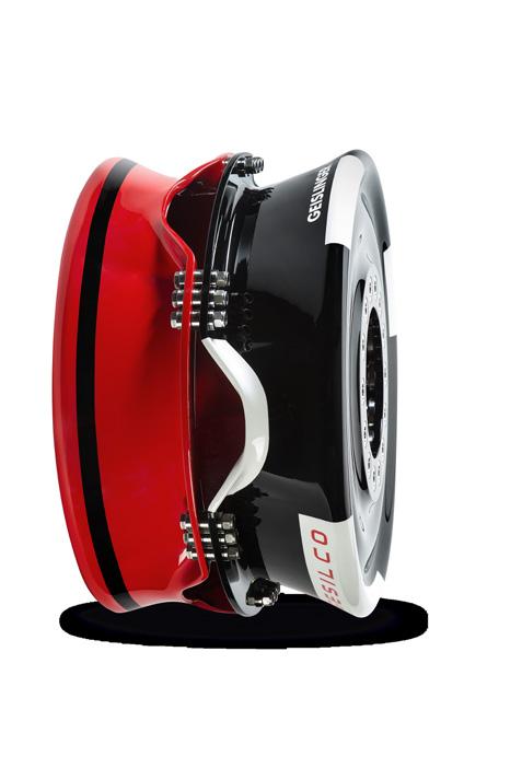
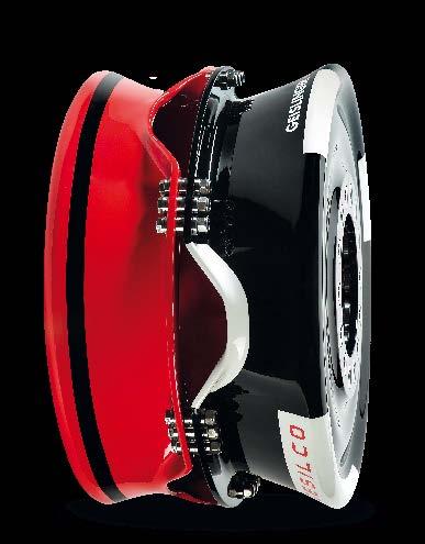
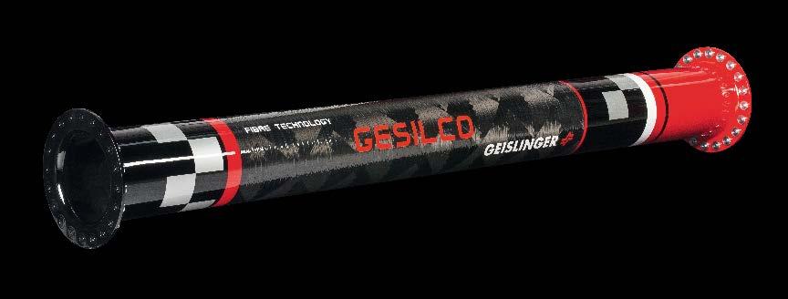
2 The Geislinger Gesilco product range is based on more than 20 years of experience in developing fibre composite couplings and shafts. The maintenance-free composite membranes enable a lightweight, highly flexible misalignment coupling design. Our corrugated carbon fibre membranes provide the lowest reaction force possible. This technology increases the system s reliability by protecting the drive line and bearings from overload. Different designs provide easy adaption to various connection interfaces. Description The main components of the Geislinger Gesilco coupling are: Maintenance-free composite membranes Composite shafts or one-piece intermediate sections Spacers for length adjustment to accommodate the installation situation Our couplings are made from advanced materials which are lifetime-calculated. They provide superior chemical resistance. Geislinger Gesilco shafts feature one-piece manufacturing with an included composite flange. This combination reduces the weight by approximately 50% compared to other composite shaft line solutions. Outstanding shock capabilities and excellent acoustic attenuation further underline its use in advanced vessels running at high speeds. Applications Marine Wind power Power generation Rail Industrial applications Gesilco Monobrane Advantages Lightweight Maintenance-free Excellent acoustic attenuation Low reaction force Gesilco Composhaft Technical Data Torque range: up to 16 MNm Ambient temperature: -45 C to 100 C Angular misalignments: up to 6 Gesilco Classic Coupling Geislinger Gesilco Disc
3 Preamble This catalog replaces all old catalog versions. The content of this catalog is indicative and - based on new developments -Geislinger reserves the right to change the content without prior notice. All duplication, reprinting and translation rights are reserved. Should you have questions, remarks or inquiries please contact us per (info@geislinger.com) or telephone ( ). The latest version of all Geislinger catalogs can be found on our website Geislinger.com. Geislinger GmbH, 5300 Hallwang, Austria
4 Index Gesilco Coupling Description... 2 Designation... 8 Selection Technical Data Examples Geislinger GmbH, 5300 Hallwang, Austria Gesilco Catalog / 53

5 Gesilco Coupling Description Gesilco Coupling Application The Geislinger Gesilco coupling has been designed to compensate for radial, axial and angular misalignments. This versatility allows Gesilco couplings to connect resiliently mounted engines to power trains and / or compensate for misalignments in virtually any other application. Due to the coupling s low mass and excellent sound insulation character, it is possible to economically design low noise installations that were formerly prohibitively expensive. Combination of a classic Geislinger torsionally elastic coupling and a Gesilco coupling results in an excellent functional separation of torsional isolation / damping (Geislinger Coupling) and high misalignment compensation (Gesilco coupling) with extremely low reaction forces. As an added benefit, a significantly reduced coupling length can be realized by mounting the classic Geislinger Coupling inside the Gesilco coupling. Some illustrations can be seen in the chapter Examples. Coupling Design The standard design of the patented Gesilco Butterfly BF coupling (Fig.1) consists of two membranes, an intermediate shaft and two flanges. Membranes, intermediate shafts and flanges are manufactured as a single piece, advanced composite structure. The halves of the coupling are bolted together at the flanges with fitted bolts. By use of variable thickness spacers, installation tolerances and centering recess can be compensated. At the inner radius of the membranes fitted steel ring inserts into drilled holes are foreseen. Prestressed screws are used to connect the membranes to the driving and driven components. Fig. 1 Membranes Flanges Inserts Fitted bolts Intermediate shaft Geislinger GmbH, 5300 Hallwang, Austria Gesilco Catalog / 53

.")

6 It is possible to adjust the Gesilco BF coupling to compensate for axial misalignment (i.e. washer thickness influences the overall length of the coupling): Fig. 2 HSO-Design: The Gesilco BF coupling inner flange bolts are mounted through the openings. See fig.3. Afterwards the coupling halves are turned into the operating position and bolted together. See fig. 4. Fig. 3 Fig. 4 Openings for mounting of inner flange bolts The modified design of the BF coupling is the Monobrane MB coupling (Fig. 5). This design has the same membrane design like the BF coupling but an intermediate flange which is arranged at a smaller diameter. This design allows the connection of the coupling directly to a Gesilco composite shaft. Geislinger GmbH, 5300 Hallwang, Austria Gesilco Catalog / 53
 consists of two membranes and an intermediate shaft made of advanced composites.")
7 Fig. 5 Flanges Composite shaft Membrane Intermediate shaft The standard design of the patented Gesilco Classic CI coupling (Fig.6) consists of two membranes and an intermediate shaft made of advanced composites. The membranes and the intermediate shaft are bonded together at the inside diameter of the membrane by a tapered collar. The membrane and tapered collar are constructed as a single piece. Fitted steel ring inserts at the outer radius of the membranes are inserted into the coupling for reinforcement. Pre-stressed screws are used to connect the membranes to the driving and driven components. Fig. 6 Membranes Inserts Intermediate shaft Geislinger GmbH, 5300 Hallwang, Austria Gesilco Catalog / 53

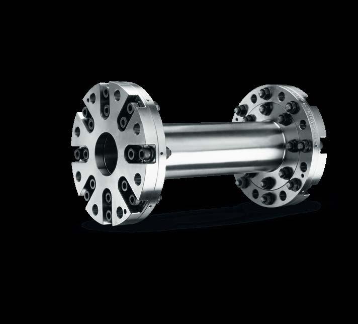
8 The standard design of the patented Gesilco Composhaft CS coupling (Fig.7) consists of two separate double membranes and an intermediate shaft made of advanced composites. The membranes and the intermediate shaft are bolted together at the flanges with fitted bolts. By use of variable thickness spacers, installation tolerances and centering recess can be compensated. Pre-stressed screws are used to connect the membranes to the driving and driven components. The Composhaft can transmit the same torque and the same misalignments with a smaller outer diameter compared to the Butterfly and Classic coupling. Fig. 7 Membranes Fitted bolts Intermediate shaft The Gesilco membranes are corrugated with decreasing wall thickness as the diameter increases. The superior advantages of the corrugated membrane design, in comparison to a flat membrane, are higher deflection capacity and lower, almost linear reaction forces. Geislinger GmbH, 5300 Hallwang, Austria Gesilco Catalog / 53

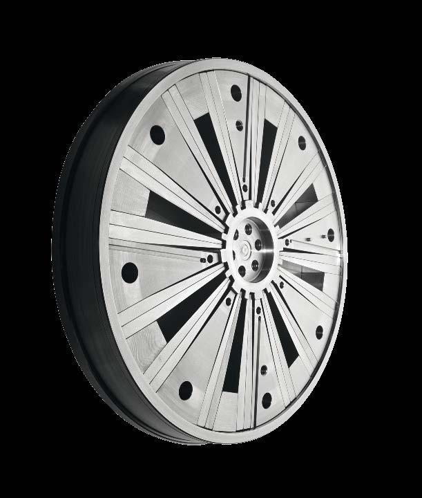
9 The standard design of the Gesilco Disc DI coupling (Fig.8) consists of one flat membrane, which is completely made of composite materials. The Disc is mainly used for diesel-electrically drives with single bearing generators. Due to the use of long-fibre reinforced composites the Gesilco Disc is able to carry the generator load and of providing very low reaction forces in case of thermal elongation. The mix of carbon fibre and glass fibre ensures high strength, excellent shock torque resistance (short circuit) and electrical isolation at the same time. The coupling is bolted at the outer diameter to the flywheel of the engine and at the inner diameter to the flange of the single bearing generator. Fig. 8 Flanges Inserts Membrane Coupling Materials Membranes and intermediate shafts of Gesilco couplings are made of advanced composites. Depending on the application, glass and carbon fibers with formulated epoxy resins are used. These materials, commonly used in aerospace structural applications, are processed by a special manufacturing method. This method provides highly consistent material properties from part to part. The membranes can be tailored to any required geometric and structural parameter. Filament wound, fiber reinforced tubes are used for the intermediate shafts. Glass fiber reinforced epoxy resins are non-magnetic and electrically non-conductive materials. Coupling Installation The coupling can be adapted to general installation parameters. Due to the Gesilco coupling s design flexibility, complicated installation configurations can be realized, according to customer s requirements. During the initial installation of a Gesilco coupling, care must be taken to ensure the static misalignments are minimized. This is important because a permanent static deflection decreases the lifetime of the coupling. Geislinger GmbH, 5300 Hallwang, Austria Gesilco Catalog / 53
10 Permissible Misalignments of a Gesilco Coupling Each Gesilco membrane is able to compensate for angular and axial misalignments. In order to compensate for axial misalignment, only one membrane is required. In radial direction, a single Gesilco membrane is relatively stiff. The combination of two membranes, coupled by a given length, allows for compensation of radial, angular and axial misalignments. Reaction forces caused by axial and angular deflections are nearly linear within a wide range. Sound Insulation Due to the advanced composite material s low mass, low axial and radial and homokinetic torque transmission, Gesilco couplings have excellent sound insulating properties in comparison with other couplings. Approvals Gesilco couplings have been developed in accordance with DIN/ISO 9001 standards. The couplings can be delivered with certificates from all major classification societies. Advantages of Gesilco Coupling Extremely low mass Highest degree of sound insulation Maintenance free Four standard Gesilco coupling designs are presented in this catalogue. Each design is presented with different levels of angular deflection capacity. The Composite material that comprises the coupling s membranes is asymmetrically arranged. Therefore, the couplings are defined as semi reversible. Geislinger GmbH, 5300 Hallwang, Austria Gesilco Catalog / 53
11 Designation The Coupling Designation has the following Significance CI 110/50/2H CI Gesilco coupling with internally located intermediate shaft (type Classic ) 110 nominal outside diameter of the coupling [cm] 50 series 2 number of membranes H semi reversible BF 100/50/2H BF Gesilco coupling with split intermediate shaft at the O.D. (type Butterfly ) 100 nominal outside diameter of the coupling [cm] 50 series 2 number of membranes H semi reversible CS 100/40/2H CS Gesilco coupling with double membranes and internally located intermediate shaft (type Composhaft ) 100 nominal outside diameter of the coupling [cm] 40 series 2 number of double membrane sets H semi reversible MB 90/35/1H MB Gesilco coupling with one membrane and two flanges (type Monobrane ) 90 nominal outside diameter of the coupling [cm] 35 series 1 number of membranes H semi reversible DI 70/2/1HS DI Gesilco Disc 70 nominal outside diameter of the coupling [cm] 2 series 1 number of double membrane sets H semi reversible S manufacturing technique Geislinger GmbH, 5300 Hallwang, Austria Gesilco Catalog / 53
12 Series Series 42 Series 50 Series 35 Series 40 Series 50 Series 35 Series 40 Series 60 Series 2 K w, = 48 mrad (type CI) max K w, = 55 mrad (type CI) max K w, = 40 mrad (type BF) max K w, = 45 mrad (type BF) max K w, = 55 mrad (type BF) max K w, = 40 mrad (type CS) max K w, = 44 mrad (type CS) max K w, = 55 mrad (type CS) max K w, = 1.75 mrad (type DI) max Coupling type BF series 35 and coupling type CS series 40 have corresponding torque range and connection dimensions. Coupling type BF series 35, 40 and 50 have corresponding connection dimensions with coupling type CS series 35 and 40. Geislinger GmbH, 5300 Hallwang, Austria Gesilco Catalog / 53
13 Selection The technical data for the coupling series mentioned above are given in the technical data section. The selection of a coupling should first take into account the required deflection capacity and then the required mean torque. Nominal Torque T KN The mean torque T is calculated from the engine power P and the engine speed n T P n T mean torque knm P engine power kw n engine speed min -1 The coupling size should be selected so that the nominal torque of the coupling T KN is higher than or equal to the mean torque to be transmitted. T KN T It should be noted that the selection of a coupling with a higher nominal torque than the application s operational mean torque (in the same series of membranes) does not result in a higher angular deflection capacity. Angular deflection capacity remains constant within the same series of membranes. Geislinger GmbH, 5300 Hallwang, Austria Gesilco Catalog / 53
14 Permissible Elastic Vibratory Torque T el for CI, BF and CS couplings In addition to the static nominal torque T KN the coupling can transmit a vibratory torque. Transient vibratory torque limit values (i.e. moving through resonances) and continuous vibratory torque limit values are shown in Fig.9. The lower the mean torque T is, the higher the permissible vibratory torque T el can be. The limit values shown in Fig. 9 must not be exceeded, even in the case of one cylinder misfiring. Fig. 9 Type H, semi reversible Y T T el. KN perm. elast vibratory torque nominal torque X T T KN mean torque nominal torque Reverse: Y = X Forward: 0 X 1 Y = X 1 < X 1.3 Y = 1.3 X The Gesilco Disc DI coupling has much higher vibratory torque limits, which are specified in the table on page 30. Geislinger GmbH, 5300 Hallwang, Austria Gesilco Catalog / 53
15 Permissible Transient Shock Torque for Gesilco couplings Transient shock torques up to 2.5 times of the nominal torque are allowed for a limited number of load cycles. Torsional Vibration Calculation For the purpose of analysis, the Gesilco coupling is basically considered a torsionally stiff coupling. In order to perform the necessary torsional vibration calculations, one must use: torsional es, mass moments of inertia and the undimensioned damping factors (given in the technical data section of the catalogue). The undimensioned damping factor is defined as the ratio of damping torque T d to elastic torque T e. κ T d T e T T d e undimensioned damping factor damping torque elastic torque Permissible Misalignment Values A coupling s lifetime can be theoretically determined by analyzing an applications load spectrum data (magnitudes and frequencies). In fact, misalignment capacities of the Gesilco coupling are defined by predetermined load cycle values. Therefore, the data tables that follow show angular deflection capacities (transient and continuous) along with their corresponding load cycles. Since the correct coupling selection is predominately influenced by the expected lifetime or load cycles, it is very important to determine accurate values for the required transient and continuous deflections. When accurate deflection data are available, a more suitable and economical coupling can be selected. Permissible combinations of angular and axial deformation of the coupling can be calculated using the formulas in the chapter Calculation of the Maximum Misalignment Capacity of various Gesilco Coupling Combinations. If it is required, axial and angular misalignment capacities can be shown for each coupling as load versus deflection diagrams (please contact Geislinger). Geislinger GmbH, 5300 Hallwang, Austria Gesilco Catalog / 53
16 Axial Misalignment Wa Geislinger Gesilco An axial misalignment W a is the deviation from the theoretical nominal length of the coupling. This deviation in length is caused by axial displacements of the adjoining shafts. Reasons for axial displacements include: errors in assembly distances, shaft movements, variations in foundations (i.e. resiliently mounted engines), or thermal expansion. Axial misalignments can be compensated using one or two membranes in series. K a, max (transient) is the maximum permissible axial misalignment capacity of one membrane and must not be exceeded during operation. Using the formula given in the selection guidelines, K a, max can be calculated from the maximum permissible angular deflection capacity K w, max (transient) and the geometry parameter i of the membrane. Radial Misalignment Wr Radial misalignment W r is the movement between driving and the driven shafts in a perpendicular direction (radial) to the axis of rotation. Radial misalignments can only be accommodated by use of two membranes with angular deflection capacity K w. Causes for radial misalignment are: assembly errors, shaft displacements, thermal expansions or elastically mounted driving or driven shafts. K w, max (transient) is the maximum permissible angular deflection capacity of one membrane and must not be exceeded by static and dynamic misalignments during operation. K w, max (transient) has constant value for each series. The maximum permissible radial misalignment capacity of the coupling depends on the bending length L b (distance between the planes of the membranes). Based on the bending length, K w, max (transient) and the formulas that follow, each coupling s max permissible misalignment capacity can be determined. Angular Misalignment Ww The angular misalignment W w is defined as the inclination of the axis of rotation between the driving and the driven sides of the coupling. Angular misalignment W w can be compensated by using one membrane with a given angular deflection capacity K w. K w, max (transient) is defined as the maximum permissible angular deflection of one membrane and should not be exceeded during operation. K w, max (transient) is constant for each series. The relationship between axial and angular misalignments is shown in the formulae of the following chapter. Geislinger GmbH, 5300 Hallwang, Austria Gesilco Catalog / 53
17 Calculation of the Maximum Misalignment Capacity Connection of two shafts using one Gesilco Membrane This combination compensates for axial W a and angular W w misalignments. W a W w W a W w Continuous ΔW w ΔW a i ΔK w Transient ΔW w ΔW a ΔK i w, max W a axial misalignment mm W w angular misalignment rad i geometric parameter of the membrane mm K w max. angular deflection of one membrane (continuous) rad K w, max max. angular deflection of one membrane (transient) rad (For values of K w, K w, max and i, see Technical Data ) Geislinger GmbH, 5300 Hallwang, Austria Gesilco Catalog / 53
18 Connection of two shafts using two Gesilco Membranes with an intermediate shaft (W-Arrangement) This combination compensates for axial W a and angular W w misalignments. For both membranes, it must be proven that the maximum angular misalignment does not exceed the coupling s maximum permissible angular deflection capacity. 2 x W a W w, 1 W a W a W a W a W w, 2 Continuous ΔW ΔW w, 1 w, 2 ΔW a ΔK i ΔW a ΔK i w w Transient ΔW ΔW w, 1 w, 2 ΔW a ΔK i ΔW a ΔK i w, max w, max W a axial misalignment mm W w,1 angle between input and intermediate shaft rad W w,2 angle between intermediate and output shaft rad i geometric parameter of the membrane mm K w max. angular deflection of one membrane (continuous) rad K w, max max. angular deflection of one membrane (transient) rad 1 First membrane 2 Second membrane ( K w, K w, max and i, see chapter Technical Data ) Geislinger GmbH, 5300 Hallwang, Austria Gesilco Catalog / 53
19 Connection of two shafts using two Gesilco Membranes with an Intermediate Shaft (Z-Arrangement) This combination compensates axial W a and radial W r misalignments L b 2 x W a W w W r W a W a W a W a Continuous Transient ΔW r ΔW a L i b ΔW ΔW r a L i b ΔK ΔK w w, max W a axial misalignment mm W w angular misalignment rad W r radial misalignment mm i geometric parameter of the membrane mm K w max. angular deflection of one membrane (continuous) rad K w, max max. angular deflection of one membrane (transient) rad L b bending length of the coupling mm ( K w, K w, max and i, see chapter Technical Data ) Geislinger GmbH, 5300 Hallwang, Austria Gesilco Catalog / 53
20 Number of Membranes Depending on the required deflection capacity of the coupling, one or two membranes can be installed. The number of membranes selected depends on technical and economical considerations. Speed n max The maximum permissible speed for each membrane type is given in the technical data section. Temperature and Humidity Proper selection of raw materials for the coupling depends on the desired service temperature and humidity. Normally, the Gesilco coupling is designed for an ambient temperature of 80 C continuous engine room operation and 100 C for short term engine room environment. Higher temperature raw materials can be delivered upon request. Flange Connections In order to connect the coupling to a flange or shaft by the best possible method, predefined flange designs are available. In addition, Geislinger is always prepared to manufacture other connections, if economically and technically feasible. Should other assembly dimensions be required, please contact Geislinger. Geislinger GmbH, 5300 Hallwang, Austria Gesilco Catalog / 53
21 Membrane`s Spring Rates Torsional Stiffness C T The Gesilco coupling can be considered torsionally stiff. Values for the torsional of membranes and intermediate shafts are given in the technical data section. Bending Stiffness C w The angular deflection W w of one Gesilco membrane produces a reaction moment M b which acts as a bending moment on the driving and driven shafts. The bending moment is proportional to the bending C w of the membrane. The reaction moment M b can be calculated as follows: M b = C w W w M b reaction moment knm C w bending knm/rad W w angular deflection rad Axial Stiffness C a The axial deflection W a of the Gesilco membrane produces a reaction force F a, which acts as an axial force on the driving and driven shafts. The axial force is proportional to the axial C a of the membrane. F a = C a W a F a axial reaction force N C a axial N/mm W a axial deflection mm Radial Loading of Gesilco Membranes Due to the Gesilco membrane s high radial, any radial loading of the membrane should be avoided. In the case of radial misalignment, a dual membrane coupling is necessary. Reaction Forces of Different Gesilco Coupling Combinations In the following chapter, the calculation of membrane reaction forces, due to torque and elastic deflection, are shown for different Gesilco coupling arrangements. For a given coupling arrangement, membranes of the same series and size are always used. Geislinger GmbH, 5300 Hallwang, Austria Gesilco Catalog / 53
22 Gesilco Coupling in W-Arrangement F W w1 W w, 1 T T T F a F a F a F a W a W a F M b1 b, 1 L b W a M b2 b, 2 F F W a W w2 F a F a F a F a W w, 2 T T T M t, 1 M t, 2 M t1 M t2 M M F a M M b, 1 b, 2 (M F C t, 1 t, 2 C a C w b, 1 w L ΔW b a TΔW TΔW ΔW ΔW M w, 1 w, 2 w, 1 w, 2 b, 2 ) rad M b reaction moment due to the membranes bending knm F radial reaction force N F a axial reaction force N T mean torque knm M t reaction moment due to the mean torque T knm C w bending knm/rad C a axial N/mm W a axial misalignment mm W w,1, W w,2 angular misalignment L b bending length m Geislinger GmbH, 5300 Hallwang, Austria Gesilco Catalog / 53
23 Gesilco Coupling in Z-Arrangement F W a T F a W w, 2 T W w, 1 W a M b, 1 M b, 2 F a L b F F a T M t, 1 M t, 2 F a T M M a M M b,1 b, 2 (M F t, 1 t, 2 C a b b,1 2C C r L C w 2 w w L b F C ΔW a TΔW TΔW ΔW ΔW M w,1 w, 2 w,1 w, 2 b, 2 ) M b reaction moment due to the membrane s bending knm F radial reaction force N F a axial reaction force N T mean torque knm M t reaction moment due to mean the torque T knm C w bending knm/rad C a axial N/mm C r radial N/mm W a axial misalignment mm W w,1, W w,2 angular misalignment rad L b bending length m Geislinger GmbH, 5300 Hallwang, Austria Gesilco Catalog / 53
24 Technical Data Coupling Type CI - Series 42 Mass elastic scheme I 1 I 1 I 2 I 2 Continuous, angular deflection capacity Transient, angular deflection capacity Shock angular deflection capacity K w = 14 mrad K w, max = 29 mrad K w, max = 48 mrad C T1 C T2 C T1 M Z M Undimensioned damping factor membrane M = Undimensioned damping factor interm. shaft Z = (I 1 without steel parts) Size Nominal torque Parameter Torsional membrane Torsional intermediate shaft Bending Axial Mass moment of inertia Bending length (min) Length Max. cent. recess Outer diameter Pitch circle dia. Bolt size Diameter Mass Max. speed T KN i C T1 C T2 C w C a I 1 I 2 Lb L1 L2max D1 D2 D3 D4 m n max knm mm MNm/rad MNm/rad knm/rad N/mm kgm 2 kgm 2 mm kg min -1 CI 44/42/2H Lb Lb M Lb 3000 CI 55/42/2H Lb Lb M Lb 2400 CI 69/42/2H Lb Lb M Lb 1900 CI 87/42/2H Lb Lb M Lb 1500 CI 110/42/2H Lb Lb M Lb 1200 value for one half of the coupling, L Lb All technical data are without warranty. Modifications of dimensions and design reserved. Geislinger GmbH, 5300 Hallwang, Austria Gesilco Catalog Version / 53
25 Technical Data Coupling Type CI - Series 50 Mass elastic scheme I 1 I 1 I 2 I 2 Continuous, angular deflection capacity K w = 17 mrad Transient, angular deflection capacity K w, max = 34 mrad Shock angular deflection capacity K w, max = 55 mrad Undimensioned damping factor membrane M = Undimensioned damping factor interm. shaft Z = C T1 C T2 C T1 M Z M (I 1 without steel parts) Size Nominal torque Parameter Torsional membrane Torsional intermediate shaft Bending Axial Mass moment of inertia Bending length (min) Length Max. cent. recess Outer diameter Pitch circle dia. Bolt size Diameter Mass Max. speed T KN i C T1 C T2 C w C a I 1 I 2 Lb L1 L2max D1 D2 D3 D4 m n max knm mm MNm/rad MNm/rad knm/rad N/mm kgm 2 kgm 2 mm kg min -1 CI 44/50/2H Lb Lb M Lb 3000 CI 55/50/2H Lb Lb M Lb 2400 CI 69/50/2H Lb Lb M Lb 1900 CI 87/50/2H Lb Lb M Lb 1500 CI 110/50/2H Lb Lb M Lb 1200 value for one half of the coupling, L Lb All technical data are without warranty. Modifications of dimensions and design reserved. Geislinger GmbH, 5300 Hallwang, Austria Gesilco Catalog Version / 53
26 Technical Data Coupling Type BF Series 35 Mass elastic scheme I 3 I 2 Continuous, angular deflection capacity Transient, angular deflection capacity Shock angular deflection capacity K w = 12 mrad K w, max = 24 mrad K w, max = 40 mrad I 2 C T1 C T2 C T2 C T1 M Z Z M I 1 Undimensioned damping factor membrane M = Undimensioned damping factor interm. shaft Z = (I 1 without steel parts) Size Nominal torque Parameter Torsional membrane Torsional intermediate shaft Bending Axial Mass moment of inertia Bending length (min) Length Max. cent. recess Inner diameter Cent. diameter Pitch circle dia. Flange dia. Bolt size Mass Max. speed T KN i C T1 C T2 C w C a I 1 I 2 I 3 Lb L1 L2max D2 D3 D4 D5 D6 m n max knm mm MNm/rad MNm/rad knm/rad N/mm kgm 2 kgm 2 kgm 2 mm kg min -1 BF 50/35/2H Lb Lb Lb M Lb 3500 BF 63/35/2H Lb Lb Lb M Lb 2800 BF 80/35/2H Lb Lb Lb M Lb 2200 BF 100/35/2H Lb Lb Lb M Lb 1800 BF 110/35/2H Lb Lb Lb M Lb 1600 BF 126/35/2H Lb Lb Lb M Lb 1400 value for one half of the coupling, L Lb All technical data are without warranty. Modifications of dimensions and design reserved. Geislinger GmbH, 5300 Hallwang, Austria Gesilco Catalog Version / 53
27 Technical Data Coupling Type BF Series 40 Mass elastic scheme I 3 I 2 I 1 I 2 I 1 Continuous, angular deflection capacity Transient, angular deflection capacity Shock angular deflection capacity K w = 13 mrad K w, max = 28 mrad K w, max = 45 mrad C T1 C T2 C T2 C T1 M Z Z M Undimensioned damping factor membrane M = Undimensioned damping factor interm. shaft Z = (I 1 without steel parts) Size Nominal torque Parameter Torsional membrane Torsional intermediate shaft Bending Axial Mass moment of inertia Bending length (min) Length Max. cent. recess Inner diameter Lent. diameter Pitch circle dia. Flange dia. Bolt size Mass Max. speed T KN i C T1 C T2 C w C a I 1 I 2 I 3 Lb L1 L2max D2 D3 D4 D5 D6 m n max knm mm MNm/rad MNm/rad knm/rad N/mm kgm 2 kgm 2 kgm 2 mm kg min -1 BF 50/40/2H Lb Lb Lb M Lb 3500 BF 63/40/2H Lb Lb Lb M Lb 2800 BF 80/40/2H Lb Lb Lb M Lb 2200 BF 100/40/2H Lb Lb Lb M Lb 1800 BF 110/40/2H Lb Lb Lb M Lb 1600 BF 126/40/2H Lb Lb Lb M Lb 1400 value for one half of the coupling, L Lb All technical data are without warranty. Modifications of dimensions and design reserved. Geislinger GmbH, 5300 Hallwang, Austria Gesilco Catalog Version / 53
28 Technical Data Coupling Type BF Series 50 Continuous, angular deflection capacity K w = 17 mrad Transient, angular deflection capacity K w, max = 34 mrad Shock angular deflection capacity K w, max = 55 mrad Undimensioned damping factor membrane M = Undimensioned damping factor interm. shaft Z = I 2 I 1 Mass elastic scheme I 2 I 3 C T1 C T2 C T2 C T1 M Z Z M (I 1 without steel parts) I 1 Size Nominal torque Parameter Torsional membrane Torsional intermediate shaft Bending Axial Mass moment of inertia Bending length (min) Length Max. cent. recess Inner diameter Cent. diameter Pitch circle dia. Flange dia. Bolt size Mass Max. speed T KN i C T1 C T2 C w C a I 1 I 2 I 3 Lb L1 L2max D2 D3 D4 D5 D6 m n max knm mm MNm/rad MNm/rad knm/rad N/mm kgm 2 kgm 2 kgm 2 mm kg min -1 BF 50/50/2H Lb Lb Lb M Lb 3500 BF 63/50/2H , Lb Lb Lb M Lb 2800 BF 80/50/2H Lb Lb Lb M Lb 2200 BF 100/50/2H Lb Lb Lb M Lb 1800 BF 110/50/2H Lb Lb Lb M Lb 1600 BF 126/50/2H Lb Lb Lb M Lb 1400 value for one half of the coupling, L Lb All technical data are without warranty. Modifications of dimensions and design reserved. Geislinger GmbH, 5300 Hallwang, Austria Gesilco Catalog Version / 53
29 Technical Data Coupling Type BF Series 50 HSO Continuous, angular deflection capacity K w = 14 mrad Transient, angular deflection capacity K w, max = 28 mrad Shock angular deflection capacity K w, max = 42 mrad Undimensioned damping factor membrane M = Undimensioned damping factor interm. shaft Z = I 2 I 1 Mass elastic scheme I 2 I 3 C T1 C T2 C T2 C T1 M Z Z M (I 1 without steel parts) I 1 Size Nominal torque Parameter Torsional membrane Torsional intermediate shaft Bending Axial Mass moment of inertia Bending length (min) Length Max. cent. recess Outer diameter Cent. diameter Pitch circle dia. Flange dia. Bolt size Mass Max. speed T KN i C T1 C T2 C w C a I 1 I 2 I 3 Lb L L2max D1 D3 D4 D5 D6 m n max knm mm MNm/rad MNm/rad knm/rad N/mm kgm 2 kgm 2 kgm 2 mm kg min -1 BF 50/50/2HSO M BF 63/50/2HSO , M BF 80/50/2HSO M value for one half of the coupling, L Lb All technical data are without warranty. Modifications of dimensions and design reserved. Geislinger GmbH, 5300 Hallwang, Austria Gesilco Catalog Version / 53
30 Technical Data Coupling Type CS Series 35 Mass elastic scheme I 1 I 2 I 3 I 3 I 1 Continuous, angular deflection capacity: K w = 12 mrad Transient, angular deflection capacity K w, max = 24 mrad Shock angular deflection capacity K w, max = 40 mrad Undimensioned damping factor membrane M = Undimensioned damping factor interm. shaft Z = C T1 C T2 C T3 C T2 C T1 Z M M M M (I 1 without steel parts) I 2 Size Nominal torque Parameter Torsional membrane Torsional intermediate shaft Bending Axial Mass moment of inertia Bending length (min) Length Max. cent. recess Length Outer diameter Inner diameter Cent. diameter Pitch circle dia. Flange dia. Bolt size Mass Max. speed T KN i C T1 C T2 C T3 C w C a I 1 I 2 I 3 Lb L1 L2max L3 D1 D2 D3 D4 D5 D6 m n max knm mm MNm/rad MNm/rad MNm/rad knm/rad N/mm kgm 2 kgm 2 kgm 2 mm kg min -1 CS 48/35/2H Lb Lb M Lb 2600 CS 56/35/2H Lb Lb M Lb 2300 CS 72/35/2H Lb Lb M Lb 1800 CS 90/35/2H Lb Lb M Lb 1400 CS 110/35/2H Lb Lb M Lb 1100 value for one half of the coupling, L Lb All technical data are without warranty. Modifications of dimensions and design reserved. Geislinger GmbH, 5300 Hallwang, Austria Gesilco Catalog Version / 53
31 Technical Data Coupling Type CS Series 40 Mass elastic scheme I 1 I 2 I 3 I 3 I 1 Continuous, angular deflection capacity Transient, angular deflection capacity Shock angular deflection capacity K w = 14 mrad K w, max = 28 mrad K w, max = 44 mrad C T1 C T2 C T3 C T2 C T1 Z M M M M I 2 Undimensioned damping factor membrane M = Undimensioned damping factor interm. shaft Z = (I 1 without steel parts) Size Nominal torque Parameter Torsional membrane Torsional intermediate shaft Bending Axial Mass moment of inertia Bending length (min) Length Max. cent. recess Length Outer diameter Inner diameter Cent. diameter Pitch circle dia. Flange dia. Bolt size Mass Max. speed T KN i C T1 C T2 C T3 C w C a I 1 I 2 I 3 Lb L1 L2max L3 D1 D2 D3 D4 D5 D6 m n max knm mm MNm/ra d MNm/rad MNm/rad knm/rad N/mm kgm 2 kgm 2 kgm 2 mm kg min -1 CS 48/40/2H Lb Lb M Lb 2600 CS 56/40/2H Lb Lb M Lb 2300 CS 72/40/2H Lb Lb M Lb 1800 CS 90/40/2H Lb Lb M Lb 1400 CS 110/40/2H Lb Lb M Lb 1100 value for one half of the coupling, L Lb All technical data are without warranty. Modifications of dimensions and design reserved. Geislinger GmbH, 5300 Hallwang, Austria Gesilco Catalog Version / 53
32 Technical Data Coupling Type CS Series 60 Mass elastic scheme I 1 I 2 I 3 I 3 I 1 Continuous, angular deflection capacity Transient, angular deflection capacity shock angular deflection capacity K w = 18 mrad K w, max = 36 mrad K w, max = 55 mrad C T1 C T2 C T3 C T2 C T1 Z M M M M I 2 Undimensioned damping factor membrane M = Undimensioned damping factor interm. shaft Z = (I 1 without steel parts) Size Nominal torque Parameter Torsional membrane Torsional intermediate shaft Bending Axial Mass moment of inertia Bending length (min) Length Max. cent. recess Length Outer diameter Inner diameter Cent. diameter Pitch circle dia. Flange dia. Bolt size Mass Max. speed T KN i C T1 C T2 C T3 C w C a I 1 I 2 I 3 Lb L1 L2max L3 D1 D2 D3 D4 D5 D6 m n max knm mm MNm/ra MNm/ra MNm/rad knm/ra N/mm kgm 2 kgm 2 kgm 2 mm kg min -1 d d d CS 50/60/2H Lb Lb M Lb 2800 CS 63/60/2H Lb Lb M Lb 2200 CS 80/60/2H Lb Lb M Lb 1800 CS 100/60/2H Lb Lb M Lb 1400 CS 110/60/2H Lb Lb M Lb 1300 CS 126/60/2H Lb Lb M Lb 1100 value for one half of the coupling, L Lb All technical data are without warranty. Modifications of dimensions and design reserved. Geislinger GmbH, 5300 Hallwang, Austria Gesilco Catalog Version / 53
33 Technical Data Coupling Type DI Angular deflection capacity K w = 1.75 mrad Undimensioned damping factor membrane M = Ø D2 Ø D4 Ø D3 Ø D1 Size SAE Nominal torque Vibratory torque Parameter Torsional Bending Axial Mass moment of inertia Outer diameter Inner diameter Outer Pitch circle Inner Pitch circle Bolt size Mass Max. speed T KN T el i C T C w C a I D1 D2 D3 D4 D5 m n max knm knm mm MNm/rad knm/rad N/mm kgm 2 mm kg min -1 DI 50/2/1HS M DI 60/2/1HS M DI 70/2/1HS M DI 90/2/1HS Tailor-made M DI 110/2/1HS Tailor-made M DI 140/2/1HS Tailor-made M All technical data are without warranty. Modifications of dimensions and design reserved. Geislinger GmbH, 5300 Hallwang, Austria Gesilco Catalog Version / 53
34 Examples Gesilco BF Coupling standard design Geislinger GmbH, 5300 Hallwang, Austria Gesilco Catalog Version / 53
35 Geislinger Gesilco BF Coupling with elastomer for acoustic optimization Geislinger GmbH, 5300 Hallwang, Austria Gesilco Catalog Version / 53
36 Gesilco BF Coupling + integrated Geislinger BE Coupling Geislinger GmbH, 5300 Hallwang, Austria Gesilco Catalog Version / 53
37 Geislinger Gesilco BF Coupling + Geislinger BE Coupling + internal hub Geislinger GmbH, 5300 Hallwang, Austria Gesilco Catalog Version / 53
38 Gesilco BF Coupling + Geislinger F Coupling Geislinger GmbH, 5300 Hallwang, Austria Gesilco Catalog Version / 53
39 Geislinger Gesilco BF Coupling + Geislinger BC Coupling with elastomer for acoustic optimation Geislinger GmbH, 5300 Hallwang, Austria Gesilco Catalog Version / 53
40 Geislinger Gesilco BF HSO design + Geislinger F Coupling Geislinger GmbH, 5300 Hallwang, Austria Gesilco Catalog Version / 53
41 Gesilco CI Coupling standard design Geislinger GmbH, 5300 Hallwang, Austria Gesilco Catalog Version / 53
42 Gesilco CF Coupling + Geislinger F Coupling Geislinger GmbH, 5300 Hallwang, Austria Gesilco Catalog Version / 53
43 Gesilco CI Coupling + Geislinger BE Coupling Geislinger GmbH, 5300 Hallwang, Austria Gesilco Catalog Version / 53
44 Gesilco BI Coupling + integrated Geislinger E Coupling Geislinger GmbH, 5300 Hallwang, Austria Gesilco Catalog Version / 53
45 Geislinger Gesilco CS Coupling Geislinger GmbH, 5300 Hallwang, Austria Gesilco Catalog Version / 53
46 CS Coupling + Geislinger BE Coupling with integrated flywheel Geislinger GmbH, 5300 Hallwang, Austria Gesilco Catalog Version / 53
47 Gesilco CS Coupling + Geislinger F Coupling Geislinger GmbH, 5300 Hallwang, Austria Gesilco Catalog Version / 53
48 Geislinger Gesilco CS Coupling + Geislinger BE Coupling Geislinger GmbH, 5300 Hallwang, Austria Gesilco Catalog Version / 53
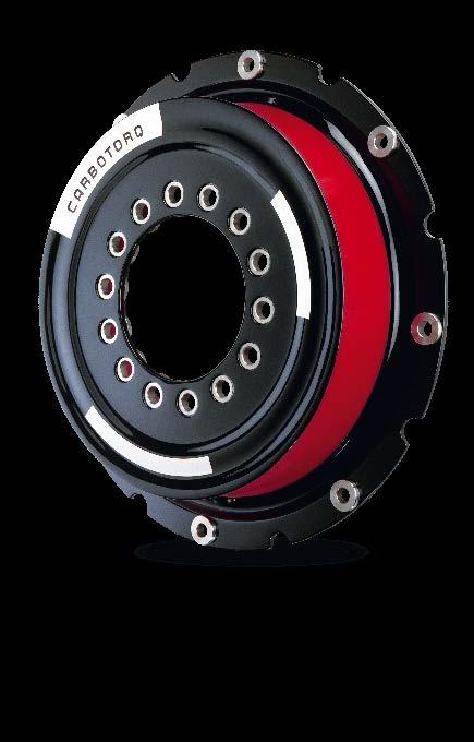
49 Geislinger Carbotorq with Gesilco Shaft and MB Coupling air supply Luftzufuhr air flow Luftstrom Geislinger GmbH, 5300 Hallwang, Austria Gesilco Catalog Version / 53
50 Geislinger MB Coupling Combination Geislinger GmbH, 5300 Hallwang, Austria Gesilco Catalog Version / 53
51 Geislinger Gesilco Disc Geislinger GmbH, 5300 Hallwang, Austria Gesilco Catalog Version / 53
52 Geislinger Compowind Coupling Geislinger GmbH, 5300 Hallwang, Austria Gesilco Catalog Version / 53
53 Compowind in geared wind turbine: rotating shaft with four-point suspension Rotor hub Gearbox Generator Compowind in direct-drive wind turbine: rotating shaft with fourpoint suspension Rotor hub Generator with bearings Geislinger GmbH, 5300 Hallwang, Austria Gesilco Catalog Version / 53
54 Compowind in geared wind turbine: king pin with two bearings and torque shaft Rotor hub Gearbox Generator Compowind in direct-drive wind turbine: king pin with two bearings and torque shaft Rotor hub Generator with bearings Geislinger GmbH, 5300 Hallwang, Austria Gesilco Catalog Version / 53
55 Compowind in geared wind turbine: rotating shaft with single momentum bearing Rotor hub Gearbox Generator Compowind in direct-drive wind turbine: rotating shaft with single momentum bearing Rotor hub Generator with bearings Geislinger GmbH, 5300 Hallwang, Austria Gesilco Catalog Version / 53
56 Compowind in direct-drive wind turbine: king pin with two bearings, hub connected to generator Rotor hub Generator with bearings Geislinger GmbH, 5300 Hallwang, Austria Gesilco Catalog Version / 53


57 Geislinger Coupling Geislinger Silenco Geislinger Carbotorq Geislinger Damper Geislinger Monitoring Geislinger Flexlink Geislinger Vdamp Geislinger Gesilco Geislinger Gesilco Shaft Geislinger GmbH, Hallwanger Landesstrasse 3, 5300 Hallwang/Salzburg, Austria, Tel , Fax , geislinger.com
LIGHTWEIGHT GEISLINGER GESILCO SHAFT
 LIGHTWEIGHT GEISLINGER GESILCO SHAFT GEISLINGER GESILCO SHAFT The Geislinger Gesilco shaft product range is based on more than 20 years experience in developing fibre composite couplings and shafts. The
THE FIBRE COMPOSITE PRODUCT LINE BY GEISLINGER
 THE FIBRE COMPOSITE BUILT TO LAST. THE COMPACT AND LIGHTWEIGHT GESILCO DESIGN PAVES THE WAY FOR GREAT OPPORTUNITIES. For 60 years Geislinger has been driven by its inventive spirit to develop innovative
MARINE RAIL MINING OIL & GAS POWER GENERATION
 MARINE RAIL MINING OIL & GAS POWER GENERATION . LEADERS IN ENGINEERING. RAIL OIL & GAS Geislinger develops and produces torsion- outstanding service life and a very high times, Geislinger locations and
Geislinger Damper. The smallest possible damper for each engine
 The Geislinger damper is capable of adjusting the natural frequency of a system and of reducing torsional vibration. Thus it reliably protects the crankshafts, camshafts, intermediate and propeller shafts
FATIGUE RESISTANT & MAINTENANCE- FREE GEISLINGER COMPOWIND
 FATIGUE RESISTANT & MAINTENANCE- FREE GEISLINGER COMPOWIND Courtesy of Vestas Wind Systems A/S GEISLINGER. LEADERS IN ENGINEERING. Geislinger develops and produces torsional vibration dampers, torsional
GEISLINGER MONITORING
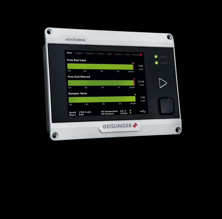
 GEISLINGER MONITORING GEISLINGER MONITORING The Geislinger Monitoring System (GMS) is a continuous monitoring and measuring system for rotating components. It is intended for use in a wide range of applications,
Introduction Components...3. Functional Description Features Standard Monitoring Functions Alarm Definition...
 Monitoring Index Introduction... 2 Components...3 Functional Description... 6 Features... 8 Standard Monitoring Functions... 9 Alarm Definition... 9 Technical Data...11 Miscellaneous...13 Applications...16
INTRODUCTION SBPT DIAPHRAGM COUPLING: FEATURES APPLICATION
 INTRODUCTION SBPT is an ISO 9001: 2000 certified company, specializing in Design and Manufactures of highly flexible Diaphragm Coupling since 1994. Advance analysis and manufacturing process have produced
PROPULSION EQUIPMENT DOCUMENTATION SHEET. Propulsion Equipment
 PROPULSION EQUIPMENT General Vessels like rescue boats, patrol boats and anchor handling boats have to show 100 percent performance, even in the most extreme conditions. These so called s pecial seagoing
CENTA POWER TRANSMISSION CENTAX-SEC CENTA X-SEC ENGLISH. Is this PDF up to date? click here for an update check!
 CENTA POWER TRANSMISSION --3-7 CENTAX-SEC ENGLISH Is this PDF up to date? click here for an update check! ONE SYSTEM. FULL FLEXIBILITY. SYSTEM COUPLING COMPONENTS APPLICATIONS TECHNICAL DATA SERVICE At
CENTA POWER TRANSMISSION CENTAMAX ENGLISH. Is this PDF up to date? click here for an update check!
 CENTA POWER TRANSMISSION CENTAMAX ENGLISH Is this PDF up to date? click here for an update check! CENTAMAX ROBUST. FOR TORSIONALLY ACTIVE DRIVES. SYSTEM COUPLING COMPONENTS TYPES APPLICATIONS TECHNICAL
Bell-house Mounted Arrangement. Highly Flexible K Coupling
 Bell-house Mounted Arrangement. Highly Flexible K Coupling K Couplings for bell-house mounted arrangements are the only coupling type providing a blind assembly connection. They are specially designed
Torsionally elastic couplings
 Torsionally elastic couplings Torsionally elastic couplings Industrial Brakes Thrusters Pressure Oil Pumps Couplings Hydraulic Buffers Cellular Buffers Rail Pliers Sheaves Hook Blocks Crane Rail Wheels
CENTAFLEX-A CF-A-17-15
 CENTA PRODUKT POWER TRANSMISSION DOKUMENTATION CF-A-17-15 ENGLISH Is this PDF up to date? click here for an update check! VERSATILE SUPERSTAR. FOR ALL APPLICATIONS. SYSTEM COMPONENTS/ADAPTATION AREAS OF
MULTI CROSS RILLO. Highly flexible tyre coupling with taper bushings
 MULTI CROSS RILLO Highly flexible tyre coupling with taper bushings Maschinenfabrik Dipl.-Ing. Herwarth Reich GmbH Vierhausstr. 53 D-44807 Bochum P.O. Box 10 20 66 D-44720 Bochum Tel.: +49 / (0)234 / 959
RIGIFLEX -N RADEX -N. Steel laminae coupling. Steel laminae coupling. You will find continuously updated data in our online catalogue at
 117 Table of contents 117 Coupling selection steel laminae coupling 119 Description of coupling 121 General information 122 Types and applications 123 Technical data 124 Standard types 126 Special types
Torsionally Stiff Steel Lamina Couplings. innovative quality products. optimal cost-performance ratio. certified according to DIN ISO 9001
 RGFLEX Torsionally Stiff Steel Lamina Couplings features: innovative quality products large-scale service optimal cost-performance ratio certified according to DN SO 0 worldwide net of distribution www.ktr.com
CLASSIFICATION OF ROLLING-ELEMENT BEARINGS
 CLASSIFICATION OF ROLLING-ELEMENT BEARINGS Ball bearings can operate at higher speed in comparison to roller bearings because they have lower friction. In particular, the balls have less viscous resistance
Flexible Couplings N-BIPEX Series
 Flexible Couplings Series /2 Overview /2 Benefits /2 Application /3 Function /3 Design /4 Technical specifications /6 Type BWN /6 Selection and ordering data /7 Spare and wear parts /7 Selection and ordering
C E NTA P OWER T R A NSMISSIO N CENTASTART-V C E N TA S TA RT-V ENGL ISH. Is this PDF up to date? click here for an update check!
 C E N TA S TA RT-V-- 05-17 C E NTA P OWER T R A NSMISSIO N ENGL ISH Is this PDF up to date? click here for an update check! Questions on product selection? We will gladly assist www.centa.info/contact
GKN Stromag highly flexible couplings for universal shafts Solutions for new technologies
 Product Catalogue Couplings GKN Stromag highly flexible couplings for universal shafts Solutions for new technologies Solutions for new technologies > The GKN Stromag IGE...FG concept > Highly flexible
Sibre All Steel Couplings
 Overview Coupling is device to transmit torque from driving side to driven side and also has function of compensation of axial,radial,angular misalignment which generated by manufacturing, installation
(d) Bore Size Check from Dimensions table (page 112) that chosen flanges can accommodate required bores.
 Bore Size Check from Dimensions table (page 112) that chosen flanges can accommodate required bores.") Fenaflex Couplings The Fenaflex coupling is a highly flexible, torsionally elastic coupling offering versatility to designers and engineers with a choice of flange combinations to suit most applications.
Fenaflex Couplings The Fenaflex coupling is a highly flexible, torsionally elastic coupling offering versatility to designers and engineers with a choice of flange combinations to suit most applications.
Highly Flexible Couplings ELPEX Series
 Siemens AG 2015 Highly Flexible Couplings ELPEX Series /2 Overview /2 Benefits /2 Application /2 Design /4 Configuration /5 Technical data /6 Types ENG/ENGS /6 Selection and ordering data /7 Types EFG/EFGS
1. Design with Composite Materials. 2. Customer Benefits. 3. New High Speed Composite Coupling Range
 Contents: 1. Design with Composite Materials 2. Customer Benefits 3. New High Speed Composite Coupling Range 1. Design with Composite Materials All high capacity dry couplings are today designed in steel
Shaft Couplings Tru-Line Flange-Couplings Rigid Shaft Couplings Flexible Couplings
 Shaft Couplings Tru-Line Flange-Couplings Rigid Shaft Couplings Flexible Couplings Edition 2015/2016 RINGSPANN Registered Trademark of RINGSPANN GmbH, Bad Homburg Table of Contents Tru-Line Flange-Couplings
Shaft Couplings Flange-Couplings Rigid Shaft Couplings Flexible Couplings
 Shaft Couplings Flange-Couplings Rigid Shaft Couplings Flexible Couplings 44 Edition 2013/2014 RINGSPANN Registered Trademark of RINGSPANN GmbH, Bad Homburg 2 Table of Contents Flange-Couplings Page Flange-Couplings
DYNAFLEX ELASTOMERIC FLEXIBLE COUPLINGS
 Page 103 of 124 Dynaflex LCR Series Couplings Rated: 4 to 135 hp at 2000 rpm LORD Dynaflex LCR Series Couplings are ring-type couplings developed to overcome numerous torsional problems associated with
Vibration damping precision couplings
 Vibration damping precision couplings In light of the advantages of elasticity, strength, resilience, and damping effects, elastomer materials are now being used in most areas of mechanical engineering.
Flexible Couplings RUPEX Series
 Flexible Couplings RUPEX Series /2 Overview /2 Benefits /2 Application /2 Design /4 Function /4 Technical data /6 Type RWN hub material grey cast iron /6 Selection and ordering data / Type RWS hub material
Standard with cone bushing. Backlash-free Safety Clutch
 EAS -Compact ratchetting clutch/synchronous clutch The Backlash-free Safety Clutch for Standard with cone bushing Packaging Machinery Machine Tools Paper Machinery Indexing Drives Servo Motors EAS -NC
Compact Modules. with ball screw drive and toothed belt drive R310EN 2602 ( ) The Drive & Control Company
 The Drive & Control Company") with ball screw drive and toothed belt drive R310EN 2602 (2007.02) The Drive & Control Company Bosch Rexroth AG Linear Motion and Assembly Technologies Ball Rail Systems Roller Rail Systems Linear Bushings
with ball screw drive and toothed belt drive R310EN 2602 (2007.02) The Drive & Control Company Bosch Rexroth AG Linear Motion and Assembly Technologies Ball Rail Systems Roller Rail Systems Linear Bushings
Inkoturn couplings. INKOMA - GROUP Couplings. Product description. Inkoturn couplings IKT. FRANCIS AND FRANCIS Ltd.
 Product description The INKOM Inkoturn coupling (IKT) is a flexible coupling with high torsional rigidity, which has been developed for applications requiring high speed and where shaft is present. INKOM
Flexible Couplings BIPEX Series
 Siemens AG 2011 Flexible Couplings BIPEX Series /2 Overview /2 Benefits /2 Application /3 Design /4 Technical data /5 Type BWN /5 Selection and ordering data /6 Type BWT /6 Selection and ordering data
Composite Long Shaft Coupling Design for Cooling Towers
 Composite Long Shaft Coupling Design for Cooling Towers Junwoo Bae 1,#, JongHun Kang 2, HyoungWoo Lee 2, Seungkeun Jeong 1 and SooKeun Park 3,* 1 JAC Coupling Co., Ltd., Busan, South Korea. 2 Department
Coupling description. Disc pack with bolts
 Coupling description RADEX -N couplings are designed to transmit torque between drive and driven components via steel hubs and flexible metallic elements commonly known as discs. The combination of these
Flexible Couplings and Hub-shaft Connections COUPLINGS
 Flexible Couplings and Hub-shaft Connections COUPLINGS High-reliability Metal Plate Spring Format Realizing Its Best Shape Through Finite Element Analysis is an ultrahigh-rigidity flexible coupling derived
Accessories smart additions for efficiency and intelligent performance
 smart additions for efficiency and intelligent performance Metal bellows couplings Perfectionists you can count on Metal bellows couplings are designed for the highest requirements in servo drive technology.
 heet: 1 of 22 Backlash-free, torsionally stiff and maintenance-free coupling Type with setscrew Type with clamping hubs Type KN (Taper hubs) Type M with setscrew Type M with clamping hubs Type PI 11-3379-883
TOOLFLEX RADEX -NC. Backlash-free shaft couplings: backlash-free flexible shaft couplings. backlash-free torsionally stiff bellow-type couplings
 Backlash-free shaft couplings: ROTEX GS backlash-free flexible shaft couplings TOOLFLEX backlash-free torsionally stiff bellow-type couplings RADEX -NC backlash-free torsionally stiff servo lamina coupling
TOOLFLEX Operating-/Assembly Instructions
 D-807 Rheine heet: 5810 EN 1 of 19 Backlash-free, torsionally stiff and maintenance-free coupling is a backlash-free, torsionally stiff and maintenance-free metal bellow-type coupling designed to be used
For advanced drive technology. Backlash-free shaft couplings: TOOLFLEX. Backlash-free shaft couplings ROTEX GS TOOLFLEX. Metal bellow-type couplings
 Backlash-free shaft couplings: ROTEX GS Backlash-free shaft couplings ROTEX GS TOOLFLEX TOOLFLEX Metal bellow-type couplings 9 Backlash-free shaft coupling Technical description ROTEX GS is a 3-part, axial
SCHMIDT-KUPPLUNG GmbH
 Schmidt-Kupplung SCHMIDT-KUPPLUNG GmbH Schmidt-Kupplung About us About us In the early 1960s Richard Schmidt developed of propulsion systems for rockets in a zero-gravity environment. Among the possible
BoWex FLE-PA. BoWex FLE-PAC. KTR-N Sheet: Edition: EN 1 of BoWex FLE-PA / FLE-PAC Operating/Assembly instructions
 1 of 17 is a torsionally rigid flange coupling. It is able to compensate for shaft misalignment, for example caused by manufacturing inaccuracies, thermal expansion, etc. BoWex FLE-PA BoWex FLE-PAC Drawn:
DYNAFLEX ELASTOMERIC FLEXIBLE COUPLINGS. Dynaflex Elastomeric Flexible Couplings.
 Page 87 of 124 Powertrain component life is determined by the load spectrum each component will experience during the machine s service life. Reciprocating engines, such as spark-ignited gasoline and compression-ignited
TYPE HSFE/HLFE/HTFE H SERIES HIGH PERFORMANCE COUPLINGS
 A High Strength Stainless Steel Flexible Membranes B Overload Collars C Flanged Connections D Shrouded bolts B C D A Product Description John Crane s HSFE/HLFE/HTFE s feature a factory assembled transmission
BoWex FLE-PA DBGM BoWex-ELASTIC DBP
 BoWex FLE-PA DBGM BoWex-ELASTIC DBP Flange coupling for I. C.-engines BoWex BoWex-FLE-PA BoWex ELASTIC BoWex FLE-PA couplings are torsionally rigid curved-tooth flange couplings, made from a combination
B.TECH III Year I Semester (R09) Regular & Supplementary Examinations November 2012 DYNAMICS OF MACHINERY
 Regular & Supplementary Examinations November 2012 DYNAMICS OF MACHINERY") 1 B.TECH III Year I Semester (R09) Regular & Supplementary Examinations November 2012 DYNAMICS OF MACHINERY (Mechanical Engineering) Time: 3 hours Max. Marks: 70 Answer any FIVE questions All questions
1 B.TECH III Year I Semester (R09) Regular & Supplementary Examinations November 2012 DYNAMICS OF MACHINERY (Mechanical Engineering) Time: 3 hours Max. Marks: 70 Answer any FIVE questions All questions
LTI Cooling Tower Drive Shafts
 LTI Cooling Tower Drive Shafts Highlights: Outstanding performance evolved from a helicopter heritage Designed specifically for cooling tower duty 100% fully integral carbon fiber epoxy construction. No
Highly Flexible Couplings ELPEX-S Series
 Highly Flexible Couplings ELPEX-S Series /2 Overview /2 Benefits /2 Application /2 Design /4 Function /4 Configuration /6 Technical data /9 Type E /9 Selection and ordering data /10 Type ESD /10 Selection
DRIVE-TECHNOLOGY INKOMA - GROUP. Inkoturn couplings
 INKOM-GROUPINKOM - DRIVE-TECHNOLOGY GROUP Inkoturn couplings INKOM-GROUP Headoffice Sitz der INKOM Maschinenbau GmbH Neue Reihe 44 D - 3862 Schandelah - Germany phone: +49/(0)5306-922-0 fax: +49/(0)5306-922-50
BACKLASH FREE AND STANDARD JAW COUPLING
 BACKLASH FREE AND STANDARD JAW COUPLING Up to 9.600 Nm of torque and 130 mm bore GAS/SG e GAS 25 Technology for Safety GAS/SG-ST - backlash free jaw coupling «in steel»: introduction Made in steel fully
TYPE HSRE/HLRE/HTRE H SERIES HIGH PERFORMANCE COUPLINGS
 A High Strength Stainless Steel Flexible Membranes B Overload Collars C Trim Balance Holes D Shrouded Bolts A C B D Product Description John Crane s Metastream HSRE/HLRE/HTRE reduced moment couplings use
III B.Tech I Semester Supplementary Examinations, May/June
 Set No. 1 III B.Tech I Semester Supplementary Examinations, May/June - 2015 1 a) Derive the expression for Gyroscopic Couple? b) A disc with radius of gyration of 60mm and a mass of 4kg is mounted centrally
Power Transmission Solutions
 RINGFEDER Products are available from MARYLAND METRICS Power Transmission Solutions 11 2011 Partners for performance RINGFEDER Products are available from MARYLAND METRICS P.O. Box 261 Owings Mills, MD
Highly Flexible Couplings ELPEX-B Series
 Siemens AG 2015 Highly Flexible Couplings ELPEX-B Series /2 Overview /2 Benefits /2 Application /2 Design / Technical data /5 Type EBWN /5 Selection and ordering data /6 Type EBWT /6 Selection and ordering
RADEX -N Composite Operating/Assembly instructions
 1 of 14 RADEX -N is a torsionally stiff flexible steel lamina coupling. It is able to compensate for shaft misalignment, for example caused by thermal expansion, etc. note ISO 101. Drawn: 0.05.15 Kb/Wig
BACKLASH FREE AND STANDARD JAW COUPLING
 BACKLASH FREE AND STANDARD JAW COUPLING Up to 9.600 Nm of torque and 130 mm bore GAS/SG e GAS 25 Technology for Safety 10-2018 GAS/SG-ST - backlash free jaw coupling «in steel»: introduction Made in steel
BoWex Curved-tooth gear coupling, shaft coupling. BoWex-ELASTIC High flexible flange coupling. MONOLASTIC Single-part, flexible flange coupling
 Curved-tooth gear coupling, shaft coupling Torsionally rigid flange coupling U.S. Patent 5,586,938 High flexible flange coupling Single-part, flexible flange coupling EP 0853203 U.S. Patent 6,117,017 Pump
Installation and Operating Instructions for ROBA -ES couplings Type 940. _. _ Sizes 14-48
 Table of contents: Please read and observe this Operating Instruction carefully. A possible malfunction or failure of the clutch and damage may be caused by not observing it. Page 1: - Table of contents
SKF Disc Couplings. Selection
 SK Disc Couplings The SK disc coupling is the ideal solution in medium to high applications that require torsional rigidity, offer some allowance for misalignment, and do not require lubrication. These
Innovative Power Transmission. Tooth Centre Distance. Curved Tooth Couplings High-Speed Series. owner s choice
 Innovative Power Transmission Tooth Centre Distance Curved Tooth Couplings High-Speed Series owner s choice Curved Tooth Couplings High-Speed Range Safety and Reliability The safety and reliability of
Description Symbol Definition or explanation Rated torque T KN Torque that can continuously be transmitted over the entire permissible speed range
 Coupling selection Normally the is selected according to the nominal torque ( ) shown in the list of technical data, like all other coupling systems. In all cases the torque ( ) must exceed the maximum
Axial Piston Fixed Motor A2FM
 Axial Piston Fixed Motor A2FM RE 91001/06.2012 1/46 Replaces: 09.07 Data sheet Series 6 Size Nominal pressure/maximum pressure 5 315/350 bar 10 to 200 400/450 bar 250 to 1000 350/400 bar Open and closed
Shaft Couplings. Edition 2015/2016. Tru-Line Flange-Couplings Rigid Shaft Couplings Flexible Couplings
 Shaft Couplings Tru-Line Flange-Couplings Rigid Shaft Couplings Flexible Couplings Edition 2015/2016 RINGSPANN Registered Trademark of RINGSPANN GmbH, Bad Homburg 2 Table of Contents Tru-Line Flange-Couplings
PRECISION BELLOWS COUPLINGS
 PRECISION BELLOWS COUPLINGS Bellows couplings are used where precise rotation, high speeds, and dynamic motion must be transmitted. They exhibit zero backlash and a high level of torsional stiffness, offering
For advanced drive technology CLAMPEX. Shaft-Hub-Connection. KTR Precision Joints CLAMPEX
 technology CLAMPEX Shaft-Hub-Connection CLAMPEX KTR Precision Joints 07 technology Table of contents Page Brief information 09 Selection and calculation -5 CLAMPEX -Selection Shaft diameter = d 0 10 0
In-house development Own manufacturing Sole distributor in Germany Working with distributors worldwide
 In-house development Own manufacturing Sole distributor in Germany Working with distributors worldwide External Clamping devices Overview 3073 Mini-Range For very low torque transmission Very small profile
High Speed Gears - New Developments
 High Speed Gears - New Developments by T. Oeeg Contents: 1. Introduction 2. Back to Back Test Bed 3. Radial Tilting Pad Bearings 3.1 Design 3.2 Test Results 3.3 Deformation Analysis 4. Axial Tilting Pad
TORQLIGHT SAFETY COUPLINGS
 LIGHTWEIGHT AND COMPACT single-position TOQLIGHT SAFETY COUPLINGS SEIES SL 10 700 Nm THE ULTIMATE COUPLING FOM 10 700 Nm SEIES SL DESIGN / FEATUES Extremely lightweight construction Up to 60 % weight reduction
AUTOFLEX DISC COUPLINGS
 AUTOFLEX DISC COUPLINGS Contents & Coupling Application Configurations Coupling Type Typical Application Series Page No Introduction - Disc Configuration 2 Coupling Selection 3 & 4 Service Factors High
ARCUSAFLEX-VSK. Highly torsionally fl exible coupling for drive shafts. Your drive is our strength. Your strength is our drive.
 ARCUSAFLEX-VSK Highly torsionally fl exible coupling for drive shafts Your drive is our strength. Your strength is our drive. Contents Page General technical description... 3 Design and function / Materials...
Highest Precision: SPL Series
 Highest Precision: SPL Series GAM can. Just ask! If you don t see exactly what you need, let us know. We can modify the SPL Series gearboxes to meet your needs. Page 3 provides a list of commonly requested
Locking Assemblies & Locking Elements
 US 01 2016 Locking Assemblies & Locking Elements Partner for Performance www.ringfeder.com Welcome to your system supplier for every aspect of power transmission Today s RINGFEDER POWER TRANSMISSION GMBH
CENTAMAX -B. Torsionally soft couplings with precompression for independently mounted units on rigid or soft mounts. Catalog CM-B-E-06-04
 Torsionally soft couplings with precompression for independently mounted units on rigid or soft mounts Catalog CM-B-E-06-04 Power Transmission Leading by innovation For many years we have been supplying
Bearings. Rolling-contact Bearings
 Bearings A bearing is a mechanical element that limits relative motion to only the desired motion and at the same time it reduces the frictional resistance to the desired motion. Depending on the design
R10 Set No: 1 ''' ' '' '' '' Code No: R31033
 R10 Set No: 1 III B.Tech. I Semester Regular and Supplementary Examinations, December - 2013 DYNAMICS OF MACHINERY (Common to Mechanical Engineering and Automobile Engineering) Time: 3 Hours Max Marks:
FLENDER Standard Couplings
 FLENDER Standard Couplings N-BIPEX FLENDER couplings Catalog MD 10.1 N Edition October 2016 Related catalogs ARPEX MD 10.2 High Performance Couplings Bucket Elevator Drives MD 20.2 E86060-K5710-A121-A1-7600
SIT-LOCK self locking elements
 self locking elements Advantages of on the shaft-hub connection compared with traditional systems Easy assembly and disassembly Both actions take place by locking and unlocking the clamping screws with
Torsionally Rigid Disc Couplings
 US 05 2016 Torsionally Rigid Disc Couplings Partner for Performance www.ringfeder.com Welcome to your system supplier for every aspect of power transmission RINGFEDER POWER TRANSMISSION We say what we
NEW. Cone Clamping Elements Trantorque Keyless Locking Devices for very small diameters from 3 mm. E03.050e
 Cone Clamping Elements Trantorque Keyless Locking Devices for very small diameters from 3 mm NEW E03.050e Backlash free positioning Excellent concentricity Quick mounting by central clamping nut Issue
Flexible Couplings BIPEX Series
 Siemens AG 2008 Flexible Couplings BIPEX Series /2 Overview /2 Benefits /2 Application /3 Design /4 Technical data /5 Type BWN /5 Selection and ordering data /6 Type BWT /6 Selection and ordering data
CONTENT. 1. Syllabus 2. Introduction 3. Shaft 4. Coupling. Rigid coupling. Flange coupling. Sleeve (or) muff coupling Split muff coupling
 muff coupling Split muff coupling") UNIT II 1. Syllabus 2. Introduction 3. Shaft 4. Coupling Rigid coupling CONTENT Flange coupling Protected flange coupling Unprotected flange coupling Marine type flange coupling Sleeve (or) muff coupling
UNIT II 1. Syllabus 2. Introduction 3. Shaft 4. Coupling Rigid coupling CONTENT Flange coupling Protected flange coupling Unprotected flange coupling Marine type flange coupling Sleeve (or) muff coupling
PK couplings. Product description. PK couplings
 Product description The INKOMA-PK coupling is machine component designed to transmit torque between axially parallel, radially offset shafts. The coupling permits both static and dynamic stepless adjustment
Product description. PK couplings
 Product description The INKOMA-PK coupling is machine component designed to transmit torque between axially parallel, radially offset shafts. The coupling permits both static and dynamic stepless adjustment
Product overview. 10 Bosch Rexroth Corporation Compact Modules R310A 2602 ( ) Compact Modules CKK. Compact Modules with ball screw drive (CKK)
 Compact Modules CKK. Compact Modules with ball screw drive (CKK)") 10 Bosch Rexroth Corporation R310A 2602 (2008.09) CKK with ball screw drive (CKK) Product overview are precision, ready-to-install linear motion systems characterized by their high performance and compact
10 Bosch Rexroth Corporation R310A 2602 (2008.09) CKK with ball screw drive (CKK) Product overview are precision, ready-to-install linear motion systems characterized by their high performance and compact
Axial Piston Fixed Pump A17FNO Series 10
 Axial Piston Fixed Pump A17FNO Series 10 RE 91510 Issue: 06.2012 Replaces: 03.2010 Size 125 Nominal pressure 250 bar Maximum pressure 300 bar For commercial vehicles Open circuit Features Fixed pump with
GEAR-COUPLINGS. Series LX GLX S-NX
 GEAR-COUPLINGS Series LX GLX S-NX CONTENTS Application 3 Quality and production 3 Design and characteristics 3 selection 4-5 Key connections 6 Shrink-fit connections 7 Standard design with one-piece housing
RBI HI-TEC INDUSTRIAL COUPLINGS
 HIGH TORQUE LOW COST RBI HI-TEC INDUSTRIAL COUPLINGS HI-TEC RBI COUPLING General purpose, cost effective range, which is manufactured in SG iron for torques up to 44253 Lb. Ft. The Standard Range Comprises
EXPANSION JOINT SELECTION GUIDE
 EXPANSION JOINT SELECTION GUIDE The proper selection and application of an expansion joint is the determining factor in its operation and life. Improper selection and application will lead to problems
High performance metal disk coupling SERVOFLEX SFF (N)
") High performance metal disk coupling SERVOFLEX SFF (N) Best design for the latest servo motor SERVOFLEX for feed shaft which introduce the high precision clamp method Coupling outer diameter, lineup for
High performance metal disk coupling SERVOFLEX SFF (N) Best design for the latest servo motor SERVOFLEX for feed shaft which introduce the high precision clamp method Coupling outer diameter, lineup for
MAIN SHAFT SUPPORT FOR WIND TURBINE WITH A FIXED AND FLOATING BEARING CONFIGURATION
 Technical Paper MAIN SHAFT SUPPORT FOR WIND TURBINE WITH A FIXED AND FLOATING BEARING CONFIGURATION Tapered Double Inner Row Bearing Vs. Spherical Roller Bearing On The Fixed Position Laurentiu Ionescu,
Flange couplings. Please note: torque increase. Types and operating description 196
 194 Flange couplings Types and operating description 196 BoWex FLE-PA BoWex FLE-PA 198 BoWex FLE-PAC 200 Selection according to SAE standard 202 Mounting dimensions according to SAE standard 203 Programme
LIGHTWEIGHT AND COMPACT. SERIES SL Nm. single-position multi-position. THE ultimate COUPLING from Nm
 LIGHTWEIGHT AND COMPACT L SAFETY COUPLINGS TOQLIGHT SEIES SL 5 700 Nm THE ultimate COUPLING from 5 700 Nm SEIES SL DESIGN / FEATUES Extremely lightweight construction Up to 60 % weight reduction in comparison
RING-flex. Torsionally Rigid Disc Couplings US Partner for performance 1. RINGFEDER Products are available from MARYLAND METRICS
 RINGFEDER Products are available from MARYLAND METRICS RING-flex Torsionally Rigid Disc Couplings US 008 Partner for performance RINGFEDER Products are available from MARYLAND METRICS P.O. Box 6 Owings
ARCUSAFLEX. Highly torsionally flexible rubber disc coupling for internal combustion engine drives
 Your drive is our strength. Your strength is our drive. Highly torsionally flexible rubber disc for internal combustion engine drives Contents Page General... 3 Types... 4 Technical data standard version
FLEXIBLE COUPLINGS - RIGID COUPLINGS Up to Nm of torque and 205 mm bores
 Edition 10/2014 www.comintec.it FLEXIBLE COUPLINGS - RIGID COUPLINGS Up to 130.000 Nm of torque and 205 mm bores (BACKLASH FREE) Technology for Safety FLEXIBLE COUPLINGS - RIGID COUPLINGS (BACKLASH FREE):
RM Flexible Disc Coupling
 RM Flexible isc RM Selection ata apacity (kw/rpm 1 Torque (knm....6. (RPM (kg ( kgm.g. (MNm/rad (MNm/rad/m (kgm ( kgm. 1.. 6.... 1 1. 6 9. 1 6.. 9.1. 1 1. 6 1... 9.1. 6 1.... 1.1 6 1. 9. 1. 1.1 1. 6..
2. Motion relationships and torques
 2. Motion relationships and torques 2.1 Rotation angle of a single joint as a function of defl ection angle ß 1 Input rotation angle 2 Output rotation angle If a single joint is deflected by angle ß and
TORSIONALLY RIGID COUPLING
 TORSIONALLY RIGID COUPLING Up to 130.000 Nm of torque and 205 mm bore GTR 7 Technology for Safety GTR - torsionally rigid coupling: introduction Made in steel fully turned with standard treatment of phosphating.