RINGFEDER KEYLESS SHAFT/HUB CONNECTIONS LOCKING ASSEMBLIES TM LOCKING ELEMENTS TM SHRINK DISCS W-300-2
|
|
|
- Evelyn Garrett
- 6 years ago
- Views:
Transcription

1 RINGFEDER KEYLESS SHAFT/HUB CONNECTIONS LOCKING ASSEMBLIES TM LOCKING ELEMENTS TM SHRINK DISCS W-300-2
2 1 Ringfeder Corporation Catalog W Shaft-Hub Locking Devices Ringfeder unique frictional, keyless shaft-hub locking devices provide an easily adjustable and releasable mechanical shrink-fit. They offer all the advantages of shrink-fits without the problems. Torque or axial loads are transmitted by radial clamping pressures and friction between the functional surfaces of the locking device, shaft and hub. Working Principle Applications Advantages Benefits Ringfeder shaft-hub locking devices are based on the inclined plane or taper principle. Clamping forces generated by torqued up locking screws are translated into predetermined contact pressures so as to create mechanical shrink-fit connections. Ringfeder frictional shaft-hub locking devices have successfully solved shaft-hub connection problems involving: Gears Rolls Cams Levers Winches Sprockets Flanges Couplings Brake drums Sheaves Flywheels Hand wheels Clutches Fan wheels Worm gears Bevel gears Helical gears Mixer shafts Crane wheels Bucket wheels Pump impellers Turbine rotors Conveyer pulleys Ship propellers Windmill propellers Rock-cutting heads Shaft-mounted gear units Elimination of keys, keyways or splines and associated fitting costs Completely tight fit around shaft no backlash Impervious to reversing, dynamic or shock loads Transmission of high torques and axial loads Reduced machining costs Easy installation, assembly and disassembly Easy axial and angular adjustments and timing 2 Catalog W-300-2


3 Product Overview 1 TM Locking Assemblies RfN 7012 These are the original Ringfeder Locking Assemblies TM featuring doubletapered thrust rings with selfreleasing tapers. They bridge relatively large fit clearances, are easy to install, adjust or remove, but are not self-centering. A precentering hub section is usually required. These units are most commonly used on applications in general engineering to transmit high torques and axial loads utilizing larger machining tolerances. Available sizes: INCH SERIES for shafts from 3/4 to dia. METRIC SERIES for shafts from 20 mm to 1000 mm dia. 2 INTERNAL Locking Assemblies TM RfN 7013 These Locking Assemblies TM are of single-taper design with a self-locking taper providing good self-centering action and concentricity, as well as increased torque capacity. A precentering hub section is not required. Integral push-off screws for disassembly are provided. These assemblies are available in two types: Straight-thru type: RfN Flange type: RfN Flange type units fix the hub positively against their extended flange preventing axial movement during tightening. Applied wherever self-centering action and good concentricity of mounted components are essential and hubs with straight-thru bores are used. Available sizes: INCH SERIES for shafts from 1 to 4 dia. METRIC SERIES for shafts from 20 mm to 150 mm dia. 3 EXTERNAL Shrink Discs RfN 4071, 4051, 4091 The Shrink Discs are external locking devices installed over hub projections. By tightening the locking screws, the locking collars exert radial forces on the tapered ring and on the hub. After bridging the fit clearances, radial clamping pressure is generated between shaft and hub establishing a solid, frictional connection. For adjustment or removal, just unscrew the bolts. Split Shrink Discs RfN 4071-SR, 4051-SR, 4091-SR They are basically the standard Shrink Discs with two separate half inner rings offering greater mounting versatility and allowing symmetrical hub designs. Split Shrink Discs can also be used as Half Shrink Discs transmitting half the catalog rated torque. Then, either clearance or tapered holes need to be provided in the hub for the locking screws., Applied for transmission of very high torques, particularly when external clamping is advantageous and excellent concentricity is required. Available sizes: The Shrink Discs accommodate both inch and metric shafts ranging from 0.75 to 34 dia. RfC Low Inertia Series Shrink Discs Sizes 10 to 50 for smaller shaft sizes. 4 5 Shrink Discs RfN 4171 This new RfN 4171 Shrink Disc employs a single, long, shallow taper instead of opposing tapers of the traditional Ringfeder three-piece series (RfN 4071). Better centering and concentricity result, making the Shrink Disc especially suitable for highspeed applications where balance is critical. Low Inertia Series Shrink Disc for Small Shafts Heavy Duty Shrink Discs 4091 for Smaller Shafts Installation is also simplified. When the fasteners are properly torqued, the installer has a visual aid to indicate correct installation, i.e., the inner ring face should be flush with the outer ring face. Available sizes: Shafts from 3/4 to 16.5, and torques from 136 lb-ft to 860,000 lb-ft. RfC Low Inertia Series Shrink Discs Sizes 10 to 50 for smaller shaft sizes a INTERNAL TM Locking Elements RfN 8006/GSA Locking Elements TMconsist of an internal and an external tapered ring. When axial force is exerted on a set of Locking Elements TM, radial clamping pressures are generated on the shaft and in the hub bore providing a frictional connection. Upon release of the clamping force, the hub can be adjusted or removed. Low Profile Torque Wrenches The ABC s of Locking Devices Applied for lower torques and smaller shafts. By varying the clamp force, number of Locking Element TMsets and clamping arrangements, different design configurations can be achieved. Available sizes: INCH sizes (GSA Series) for shafts from 1/4 to 3 dia. METRIC sizes (RfN 8006 Series) for shafts from 6 mm to 1000 mm dia Catalog W


 Locking Assemblies TM. Fig.")


4 2 Ringfeder Locking Assemblies TM RfN 7012 & RfN 7012-IN Ringfeder Locking Assemblies TM are completely self-contained, frictional shaft-hub locking devices. Designed to generate an easily adjustable and releasable mechanical shrink-fit, they have been used successfully for many years in heavy-duty applications to transmit high torques and dynamic loads and to provide timing and releasability. Application Examples Fig. 1: Drive Pulley Drive pulley with 280 mm dia. ( ) Locking Assemblies TM and bend pulley with 95 mm dia. (3.740 ) Locking Assemblies TM. Fig. 2: Lower Band Wheels Lower band wheels of a twin band saw fastened with 7 RfN 7012-IN Locking Assemblies TM. Fig. 3: Gears Gears fitted with RfN 7012 Locking Assemblies TM. Fig. 5: Drive Pulley Drive pulley of a gondola ski lift fastened with a 300 x 375 RfN 7012 Locking Assembly TM. Fig. 4: Sprockets Input shaft for 750 HP draw works showing applications of Locking Assemblies TM and adaptor flanges. Fig. 6: Pinion Gear Pinion gear and flywheel both mounted with RfN 7012 Locking Assemblies TM. Fig. 7: Cutter Heads Cutter heads fastened with Locking Assemblies TM. 4 Catalog W-300-2
5 Selection Guide 2 1. Determine the required shaft diameter (d) or maximum torque (M t ) to be transmitted: Torque M t = 5252 x HP (lb-ft) RPM If combined torsional and axial loads are to be transmitted, calculate the resulting torque as follows: M t res M t P ax d M t cat M t res = M t 2 + ( P ax x d ) 2 M t cat 24 = resultant torque to be transmitted = actual or maximum torque to be transmitted (lb-ft) = axial load/thrust to be transmitted (lbs) = shaft diameter (inches) = maximum transmissible torque (lb-ft) of Locking Assembly TM as specified 2. Select a Locking Assembly TM for the shaft diameter (d) from the specification tables and verify that the corresponding maximum transmissible torque (M t ) meets the torque requirement. If torque is the primary requirement, select the necessary torque (M t ) from the same specification tables and determine the corresponding shaft diameter (d). Note: Required peak torque should never exceed specified transmissible torque (M t ). To increase transmissible torque (M t ): a. Install 2 or 3 Locking Assemblies TM in series, increasing transmissible torque as follows: - with 2 Locking Assemblies TM : M trans. = 2 x M t - with 3 Locking Assemblies TM : M trans. = 3 x M t - (see Fig. 8: Hub Layout and Fig. 9). The hub must be long enough to accommodate the assemblies. b. Increase screw tightening torque (M A ) by up to 20%. Transmissible torque (M t ) and contact pressures (p, p ) increase proportionately. 3. Determine the recommended minimum hub outside diameter (D N ) for the Locking Assembly TM selected from the specification tables or calculate the hub outside diameter (D N ) by using the following equation: D N D x YP + C 3 x p YP - C 3 x p Where YP = yield point of hub material (lbs/sq.in.) p = p x d/d (lbs/sq.in.) B = min. 2 x I (inches); see Example C 3 = 0.6 (one locking assembly) C 3 = 0.8 (2 or 3 Locking Assemblies TM in series) 4. Verify that the hub length (B) is adequate for the selected Locking Assembly TM ; see Example. 5. Check the applicable machining tolerance for the shaft and hub bore in the specification tables. A surface finish of 125 micro-inches for shafts and bores is generally adequate. 6. Determine the required Locking Assembly TM by specifying the size (d x D) from Tables 1 & 2 followed by the series number, e.g.: 100 x 145 RfN Fig. 8: Hub Layout Typical layout for a Locking Assembly TM installation. Note: When accurate centering of the hub is required, establish a proper fit tolerance for the pilot or centering portion of the hub. EXAMPLE A spur gear is to be mounted on a dia. shaft capable of transmitting a peak torque of 5,750 lb-ft. The gear is made of 1040 AISI steel (Y.P. 36,000 psi). Select the proper Locking Assembly TM and determine the required hub dimensions and proper machining tolerances. 1. The shaft diameter is specified at The specification tables indicate that a 3-15/16 Locking Assembly TM is capable of transmitting a torque (M t ) of 6,944 lb-ft, more than the required amount. Select the 3-15/16 Locking Assembly TM. 3. The specification tables indicate that the selected 3-15/16 Locking Assembly TM requires a minimum hub outer diameter of based on Y.P. 36,000 psi hub material. 4. The hub length (B) should be 2 x L 1. Fig. 8 indicates that L 1 = Therefore, B = 2 x = (minimum). Since the gear must be concentric within.0025, specify the following fit tolerance for the pilot bore: shaft: / bore: / According to the specification tables, the machining tolerances for the selected Locking Assembly TM are as follows: shaft: +.000/ counter bore: -.000/ However, because of the concentricity requirements for the gear, tighter tolerances are needed for the shaft and pilot bore. The counter bore tolerances for the Locking Assembly TM are / (within the permissible limits and in accordance with the fit tolerance specified in Step 4 above). 6. Order the following assembly: Size RfN Series Metric: 100 x 145 RfN 7012 Inch: 3-15/16 RfN 7012-IN Catalog W
6 2 Fig. 9 Inch Series Locking Assemblies TM RfN 7012-IN Specifications Table 1: Inch Series Locking Assembly TM RfN 7012-IN Material: Medium Carbon Steel* d = nominal Locking Assembly TM I.D. = shaft O.D. T 1 = machining tolerances for shaft (d) D = nominal Locking Assembly TM O.D. = hub counter bore I.D. T 2 = machining tolerances for counter bore (D) L, I, L 1 = width dimensions, relaxed condition M t = maximum transmissible torque p = contact pressure between Locking Assembly TM and shaft d G = metric socket head cap screw size s = metric hex key size (across flats) M A = required tightening torque per locking screw (tighten with torque wrench) d D = metric pull-out thread (under zinc-plated screws only) D N = minimum hub O.D. for single-unit installation and based on Y.P. 36,000 psi hub material (for other hub materials calculate hub O.D. per step 3 of Selection Guide) Locking Assembly TM dimensions Locking screws DIN RfN max IN d T 1 D T 2 L I L 1 M t p Qty. size s M A d D D N Size inches lb-ft psi d G mm lb-ft inches 1-3/ M 6x M M 6x M / M 6x M / M 6x M / M 6x M / M 6x M / M 6x M / M 6x M / M 8x M / M 8x M / M 8x M / M 8x M / M 8x M M 8x M / M 8x M / M 8x M / M 8x M / M 8x M / M 8x M / M 8x M / M 8x M / M 10x M / M 10x M / M 10x M / M 10x M / M 10x M M 10x M / M 10x M / M 10x M / M 10x M / M 10x M / M 10x M / M 10x M / M 12x M M 12x M / M 12x M / M 12x M / M 12x M M 12x M / M 12x M M 12x M / M 14x M M 14x M / M 14x M / M 14x M *Stainless steel available upon request. Notes: B = at least 2 x I, preferably 2 x L 1 or more P ax = axial load (thrust capacity) = M t x 24 lbs (for M t in lb-ft) d p = constant pressure between Locking Assembly TM and hub bore Values of M t, p, P ax, and p are based on lightly oiled installation (coefficient of friction µ = 0.12) p = p x d D 6 Catalog W-300-2
7 Metric Series Locking Assemblies TM RfN 7012 Specifications 2 Table 2: Metric Series Locking Assembly TM RfN 7012 Material: Medium Carbon Steel* RfN Locking Assembly TM dimensions Locking screws DIN max. Size d T 1 D T 2 L I L 1 M t p Qty. size s M A d D D N mm inches lb-ft psi d G mm lb-ft inches 20 x M 6x M x M 6x M x M 6x M x M 6x M x M 6x M x M 6x M x M 6x M x M 6x M x M 6x M x M 6x M x M 8x M x M 8x M x M 8x M x M 8x M x M 8x M x M 8x M x M 8x M x M 10x M x M 10x M x M 10x M x M 10x M x M 10x M x M 10x M x M 12x M x M 12x M x M 12x M x M 12x M x M 12x M x M 12x M x M 12x M x M 14x M x M 14x M x M 14x M x M 14x M x M 16x M x M 16x M x M 16x M x M 18x M x M 18x M x M 20x M x M 20x M x M 22x M x M 22x M x M 22x M x M 22x M x M 24X M x M 24X M x M 24X M x M 24X M *Stainless steel available upon request. For larger sizes or additional information, request catalog S76A. Ordering Example Size RfN Series Metric: 100 x 145 RfN 7012 Inch: 3-15/16 RfN 7012-IN Catalog W

8 2 Design Examples Fig. 10: Locking Assembly TM Typical Ringfeder Locking Assembly TM connection. Fig. 11: Coupling Coupling half-mounted with a RfN 7012 Locking Assembly TM. Here, the shaft is stepped to permit the largest possible hub cross-section. Fig. 12: Impeller Impeller mounted with a RfN 7012 Locking Assembly TM. Here, the locking device is protected from moisture with a bolt-on cap. Fig. 13 Hub mounted using two RfN 7012 Locking Assemblies TM to transmit twice the torque. Fig. 14 Hub fastened with two RfN 7012 Locking Assemblies TM located at opposite ends of the hub. In this arrangement twice the torque is transmitted provided the hub length is less than four times the width of the Locking Assembly TM. Bores must be concentric to each other. Fig. 15: Flat-Belt Pulley Flat-belt pulley mounted with a RfN 7012 Locking Assembly TM. 8 Catalog W-300-2
9 Installation and Removal Instructions 2 INSTALLATION 1. Verify that all contact surfaces, including the screw threads and screw head bearing surfaces, are clean and lightly oiled. Note: Do NOT use Molybdenum Disulfide, Molykote or any other similar lubricants. 2. Slide the Locking Assembly TM onto the shaft and into the hub bore, aligning them as required. 3. Tighten the locking screws gradually in the sequence illustrated in Fig. 16: Tightening Sequence as follows: a) Hand-tighten 3 or 4 equally spaced locking screws until they make contact. Align and adjust the connection. b) Hand-tighten and take up all remaining locking screws. c) Use a torque wrench to tighten the screws further to approximately one-half the specified torque (M A ). d) Using the torque wrench tighten the screws to full tightening torque (M A ). e) Verify that the screws are completely tight by applying the specified tightening torque (M A ). NOTES a) Even tightening is best accomplished by turning each screw in increments of approximately 90º. b) For the final pass it is recommended to set the torque wrench by approximately 5% over the specified tightening torque (M A ) to compensate for any possible settling. INSTALLATION TOOLS Standard torque wrench with either 1/4, 3/8, 1/2 or 3/4 square drive and suitable torque range; see Table 3: Locking Assembly TM Tightening Data for specified tightening torques (M A ). Metric hexagonal-bit socket (Fig. 17: Square Drives) for torque wrench with suitable dimension across flats (s); see Table 3: Locking Assembly TM Tightening Data. Metric hexagonal key with across flats dimension (s). NOTE: DO NOT USE IMPACT WRENCH! Since the torque is transmitted by contact pressure and friction between the frictional surfaces, the condition of the contact surfaces and the proper tightening of the locking screws are important. Fig. 16: Tightening Sequence Tightening sequence for locking screws. REMOVAL Ringfeder Locking Assemblies TM are not self-locking. The individual rings are tapered so that the inner and outer rings spring apart after the last screw has been loosened. 1 Loosen the locking screws in several steps following a diametrically opposite sequence. Do not remove the screws completely. 2 Remove the hub and Locking Assembly TM from the shaft. REMOVAL TOOL Three pull-out bolts or threaded rods with metric thread (d D ) long enough for the specific application; see Table 3: Locking Assembly TM Tightening Data. Fig. 18: Rear Thrust Ring Jams If the rear thrust ring jams, tap lightly against the screw heads to make it snap back. Fig. 17: Square Drives 1/4, 3/8, 1/2 or 3/4 square drive Table 3: Locking Assembly TM Tightening Data Fig. 19: Front Thrust Ring Jams If the front thrust ring jams, remove the three zinc-plated screws to expose the pull-out threads (d D ) of the front thrust ring. Screw in suitable bolts or threaded rods and lightly tap in an outward direction to release the front thrust ring. The pullout threads have only 3 to 5 effective threads; they are unsuitable for strong pulling forces and should be used only to remove the Locking Assembly TM. Tightening Locking Assemblies TM Torque Screw M A Screw Size (d G ) Hex Key Square Pull-Out Thread RfN 7012 RfN 7012-IN (lb-ft) (Nm) Metric Size (s) Drive Size (d D ) Metric Metric Series Inch Series 20 x 47 to 40 x 65 1 to 1-1/ M 6 5 1/4 M 8 42 x 75 to 65 x /8 to 2-9/ M 8 6 1/4 M x 110 to 95 x /4 to 3-3/ M /8 M x 145 to 160 x /16 to M /8 M x 225 to 200 x /2 to 7-7/ M /2 M x 285 to 260 x M /2 M x 355 to 300 x M /2 M x 405 to 340 x M /4 M x 455 to 420 x M /4 M x 545 to 1000 x M /4 M 30 Catalog W


10 3 Ringfeder Locking Assemblies TM RfN 7013 & RfN 7013-IN SELF-CENTERING SINGLE-TAPER DESIGN Ringfeder RfN 7013 Locking Assemblies TM are a single-taper design with a self-locking taper. The assemblies provide good self-centering action and concentricity, as well as increased torque capacity. Integral push-off screws for disassembly are provided. The assemblies are suitable for hubs with straight-thru bores and narrow hubs. A precentering hub section is not required. These assemblies are available in two types: Straight-thru type: RfN Flange type: RfN Flange type units fix the hub positively against their extended flange to prevent axial movement during tightening. RfN RfN Applications and Design Examples Fig. 20 Hub mounted with a RfN Locking Assembly TM in a straight-thru bore. Fig. 21: Turbine Runner Turbine runner mounted with a Locking Assembly TM. Fig. 22 Hub mounted with a RfN Locking Assembly TM with countersunk flange. Fig. 23 Hub mounted with a RfN Locking Assembly TM in counterbore. Fig. 24 Hub mounted with a RfN Locking Assembly TM flange outside the hub bore. Fig. 25 Typical layout for a Locking Assembly TM installation. 10 Catalog W-300-2
11 Selection Guide 3 1. Determine the required shaft diameter (d) or maximum torque (M t ) to be transmitted: Torque M t = 5252 x HP (lb-ft) RPM If combined torsional and axial loads are to be transmitted, calculate the resulting torque as follows: M t res = M t 2 + ( P ax x d ) 2 M t cat 24 M t res = resultant torque to be transmitted M t = actual or maximum torque to be transmitted (lb-ft) P ax = axial load/thrust to be transmitted (lbs) d = shaft diameter (inches) M t cat = maximum transmissible torque (lb-ft) of Locking Assembly TM as specified Note: For hollow shaft applications, please consult Ringfeder Corporation. 2. Select a Locking Assembly TM for the shaft diameter (d) from the specification tables and verify that the corresponding maximum transmissible torque (M t ) meets the torque requirement. If torque is the primary requirement, select the necessary torque (M t ) from the same specification tables and determine the corresponding shaft diameter (d). Note: Required peak torque should never exceed specified transmissible torque (M t ). 3. Determine the recommended minimum hub outside diameter (D N ) for the Locking Assembly TM selected from the specification tables or calculate the hub outside diameter (D N ) as follows: D N D x YP + C 3 x p YP - C 3 x p YP = yield point of hub material (lbs/sq.in.) p = contact pressure (lbs/sq.in.) between Locking Assembly TM and hub (see Tables 4 or 5). C 3 = form factor depending on hub design (see Fig. 26, Fig. 27, or Fig. 28). 4. Determine the applicable machining tolerances for the shaft and hub bores in Table 4 or 5. The required surface finish for shaft and hub bores is RMS 63 or better, but surface finishes should not be RMS 8 or less. Ordering Example Size RfN Series Metric: 55 x 85 RfN Inch: 2-1/4 RfN IN B B B L 2 L 2 L 2 D N D N D N b D D D Fig. 26 C 3 = 0.6 Hub pre-centered on shaft B (hub width) 2 x L 2, b L tot Fig. 27 C 3 = 0.8 Straight-thru bore B (hub width) 2 x L 2 Fig. 28 C 3 = 1 (hub width) L 2 B < 2 x L 2 Ordering Example Size RfN Series Metric: 60 x 90 RfN Inch: 2-7/8 RfN IN Catalog W
12 3 Inch Series Locking Assemblies TM RfN 7013-IN Specifications Fig. 29 Ringfeder RfN Locking Assembly TM (hub moves freely axially during tightening). d = nominal Locking Assembly TM I.D. = shaft O.D. T 1 = machining tolerances for shaft (d) D = nominal Locking Assembly TM O.D. = hub counter bore I.D. T 2 = machining tolerances for counter bore (D) L tot, L, = width dimensions, relaxed condition L 1, L 2 M t = maximum transmissible torque p = contact pressure between Locking Assembly TM and shaft p = contact pressure between Locking Assembly TM and hub bore d G = metric socket head cap screw size s = metric hex key size (across flats) M A = required tightening torque per locking screw (tighten with torque wrench) D N = minimum hub O.D. for single-unit installation based on Y.P. of 36,000 psi hub material (for other hub materials calculate hub O.D. per step 3 of the Selection Guide) Fig. 30 Ringfeder RfN Locking Assembly TM (hub axially fixed during tightening). Notes P ax = axial load (thrust capacity) = M t x 24 lbs (for M t in lb-ft) d M t, P ax, p, and p are based on a lightly oiled installation (coefficient of friction µ = 0.12) Table 4: Inch Series Locking Assemblies TM RfN & IN Material: Medium Carbon Steel* Locking screws Locking Assembly RfN TM dimensions DIN max. Size d T 1 D T 2 L tot L L 1 L 2 D 1 M t p p Qty Size s M A D N inches inches lb-ft psi 1 ) 2 ) d G mm lb-ft inches M 6x / M 6x / M 6x / M 6x / M 6x / M 6x / M 8x / M 8x / M 8x / M 8x M 8x / M 8x / M 8x / M 8x / M 8x / M 8x / M 8x / M 8x / M 10x / M 10x / M 10x M 10x / M 10x / M 10x / M 10x / M 10x / M 10x M 10x ) Number of screws in type RfN ) The number of screws in type RfN is higher to compensate for increased friction when the hub is fixed * Stainless steel upon request 12 Catalog W-300-2
13 Table 5: Metric Series Locking Assemblies TM RfN & Material: Medium Carbon Steel* Metric RfN 7013 Specifications 3 Locking screws Locking Assembly RfN TM dimensions DIN max. Size d T 1 D T 2 L tot L L 1 L 2 D 1 M t p p Qty Size s M A D N mm inches lb-ft psi 1 ) 2 ) d G mm lb-ft inches 20x M 6x x M 6x x M 6x x M 6x x M 6x x M 6x x M 6x x M 6x x M 6x x M 6x x M 8x x M 8x x M 8x x M 8x x M 8x x M 8x x M 8x x M 10x x M 10x x M 10x x M 10x x M 10x x M 10x x M 10x x M 10x x M 10x x M 12x x M 12x x M 12x ) Number of screws in type RfN ) The number of screws in type RfN is higher to compensate for increased friction when the hub is fixed * Stainless steel upon request Since the torque is transmitted by contact pressure and friction between the frictional surfaces, the condition of the contact surfaces and the proper tightening of the locking screws are important. INSTALLATION 1. Verify that all contact surfaces, including the screw threads and screw head bearing surfaces, are clean and lightly oiled. Note: Do NOT use Molybdenum Disulfide, Molykote or any other similar lubricants. 2. Slide the Locking Assembly TM onto the shaft and into the hub bore, aligning them as required. 3. Tighten the locking screws gradually in a diametrically opposite sequence as follows: a) Hand-tighten 3 or 4 equally spaced locking screws until they make contact. Align and adjust the connection. b) Hand-tighten and take up all remaining locking screws. c) Use a torque wrench to tighten the screws further to approximately one-half the specified torque (M A ). d) Using the torque wrench tighten the screws to full tightening torque (M A ). e) Verify that the screws are completely tight by applying the specified tightening torque (M A ). Installation and Removal Instructions Catalog W REMOVAL 1. Loosen all screws several turns. 2. Remove the screw adjacent to each threaded jacking hole and screw it into its corresponding jacking hole to press off the outer ring. This releases the connection. 3. Remove the hub and the Locking Assembly TM from the shaft. Leave the screws in the jacking holes until you have completely removed the Locking Assembly TM from the hub. Disassemble and clean dirty undamaged Locking Assemblies TM before re-use. TOOLS REQUIRED FOR ASSEMBLY AND REMOVAL a) Standard torque wrench with either 1/4 or 3/8 square drive and suitable torque range; see Table for specified tightening torques (M A ). b) Metric hexagonal bit socket (see Fig. 31: Square Drives) for torque wrench with suitable across flats dim. (s); see Table 3. NOTE: DO NOT USE IMPACT WRENCH! Fig. 31: Square Drives 1/4 or 3/8 square drive 13


14 4 Ringfeder Shrink Discs RfN 4071, RfN 4091 & RfN 4051 Shrink Discs are used to transmit high torques, particularly when external clamping is advantageous and a high degree of concentricity is required. Ringfeder Shrink Discs are self-contained and ready for installation over a hub projection. Applications Examples Fig. 32: Apron Feeder Drive Apron feeder drive; hydraulic power unit, Ridley Island Coal Terminal. Fig. 33: Gear Gear mounted with a Shrink Disc on a straight side press. Fig. 34: Clutch Clutch of a 2,500 ton press shaft mounted with a Shrink Disc. Fig. 35: Speed Reducer Shaft-mounted speed reducer fastened with a Shrink Disc. Fig. 36: Shrink Disc RING-flex torsionally rigid, backlash-free couplings use Ringfeder Shrink Discs to give a truly backlash-free shaft to shaft coupling. 14 Catalog W-300-2


15 4 Fig. 37: RING-flex coupling in automotive plant main conveyor drive. Fig. 38: Shrink Disc on engine flywheel coupling for diesel driven compressor. Fig. 40: Diesel engine flywheel coupling. Fig. 39: Shrink Disc on U-joint drive in sawmill equipment. Fig. 42: Rigid Flange Coupling Fig. 41: Shrink Disc on bull gear of punch press. Fig. 43: Stepped Sleeve Coupling Rigid Shrink Disc stepped sleeve coupling. Catalog W

. Figu Type Fig. 46: Universal Joint Connection Fig.")
16 4 Relative Comparison of Shrink Disc Series The original Shrink Discs are available in three series: Standard Series RfN 4071 Heavy Duty Series RfN 4091 Light Duty Series RfN 4051 SHRINK DISCS RfN 4051 LIGHT DUTY SERIES RfN 4071 STANDARD DUTY SERIES RfN 4091 HEAVY DUTY SERIES SPLIT SHRINK DISCS RfN 4051-SR LIGHT DUTY SERIES RfN 4071-SR STANDARD DUTY SERIES RfN 4091-SR HEAVY DUTY SERIES More Design Examples Shrink Disk Gear Shaftmounted Reducer Shaft-bearing Driven Shaft Fig. 44: Two Shrink Discs in line offer 2X the torque capacity of one. Fig. 45: Speed Reducer Shaft-mounted speed reducer. Illustrated stepped shaft configuration provides 2-point contact eliminating skewing during installation (installed position shown). Figu Type Fig. 46: Universal Joint Connection Fig. 47: Adapter Flanges Type HSDA Shrink Disc adapter flanges (available for Hägglunds drives). 16 Catalog W-300-2
17 General Engineering Information 4 The Maximum Transmissible Torque is a function of the shaft diameter, the coefficient of friction (µ) and the clearance between the shaft and hub. Torque is calculated using the equation: M t = P x π x d 2 W x l x µ 24 P = contact pressure between shaft and hub (psi) d W = shaft diameter (inches) I = inner ring length (inches) Coefficient of friction (µ) can vary widely depending on material and surface finish. A well-accepted number for interference fits that are lightly oiled is µ=0.12. This fig. is used to determine torque capacity listed in this catalog. If shaft and hub are assembled dry, µ=0.15 can be assumed. Tests have shown that grease-free connections can attain coefficients greater than 0.2. The transmissible torque is then increased proportionately. Hub stress calculation, which determine the material requirements for the hub, are based on multi-directional stresses. The following equation uses the maximum distortion energy theory to calculate the maximum combined stress in the hub. where: VH XH YH ZH H VH = 1 /2{( XH - YH ) 2 + ( YH - ZH ) 2 + ( ZH - XH ) 2 } + 3 H 2 = combined stress (psi) = tangential stress (psi) = radial stress (psi) = axial and bending stress (psi) = torsional shear stress (psi) Individual stress components can be determined by using the Lamé thick wall cylinder equations. (See Fig. 48). Fit clearances can also affect torque capacity. Catalog values are calculated using maximum fit clearance. See subsequent data tables for suggested tolerance allowances. These fits will allow easy assembly and disassembly. If larger clearances are required, torque will be reduced proportionately. Also, hub stresses will increase and could exceed the yield strength of the material, causing plastic deformation. Please contact us if larger fit clearances are required. Allowable hub O.D. tolerances and maximum radius allowed adjacent to the Shrink Disc are given in subsequent data tables. Materials with a minimum yield point of 50,000 psi are recommended. Because the hub is in compression, grey cast irons are suitable. Other materials can be used if combined stresses are kept below the yield point of the material. Contact our engineering department for a complete stress analysis. Hollow shafts do not act the same as solid shafts under compressive radial loads. Depending on the wall thickness there will be varying amounts of elastic deformation and consequently a reduction in torque capacity. Our engineering department can provide complete information based on your requirements. If combined torsional and axial loads are to be transmitted, calculate the torque as follows: M t res = M t 2 + ( P ax x d ) 2 M t cat 24 M t res = resultant torque to be transmitted (lb-ft) M t = actual or maximum torque to be transmitted (lb-ft) P ax = axial load-thrust to be transmitted (lbs) d W = shaft diameter (inches) M t cat = max. transmissible torque (lb-ft) of Shrink Disc TM as specified in catalog The required surface finish for both shaft and hub projection I.D. and O.D. is RMS 125 microinches or better. Fig. 48 Catalog W
18 4 Selection Guide Shrink Discs 1 Determine the shaft diameter (d w ) to be used or the maximum torque (M t ) to be transmitted. Note: For hollow shaft applications, consult Ringfeder Corporation. 2 Select a Shrink Disc from the Table for required shaft dia. (d w ) and verify that the corresponding maximum transmissible torque (M t ) meets the torque requirement. If torque is the primary requirement, select the necessary torque (M t ) from the same specification table and determine the corresponding shaft diameter (d w ). 3 Incorporate the specified dimensions of the selected Shrink Disc and required hub into your design and drawing. Indicate the specified tightening torque (M A ) for each locking screw on the drawing. 4 Establish machining tolerances (T H, T W ) for shaft, hub bore and hub outer diameter from the specification tables. Ordering Example Size RfN Series Example: 90 RfN 4071 Shrink Discs RfN 4071 Specifications Allow space for torque wrench Detail A See Detail A and Options Fig. 49: Shrink Disc Layout Shrink Disc RfN 4071 Option 1 Option 2 d T H d W T W M t D d 1 d 2 = nominal Shrink Disc TM I.D. = hub projection O.D. = specified tolerance for hub O.D. (d) = shaft size range (min.- max.) = total allowable diametrical clearance between shaft and hub bore (d W ) = maximum transmissible torque = Shrink Disc TM O.D. = bolt circle dia. = thrust ring I.D. L, L 1,L 2,e= width dimensions, relaxed condition s = head dimension across flats (mm) M A = required tightening torque per locking screw d 3 = 0.98 x d (for option 1) r = customer selectable (for option 2) P ax = M t x 24 lbs (for option 2) d W Notes 1 Tapers and screws lubricated with Molykote Gn Paste or equivalent. 2 For Series RfN 4071: Sizes 24 to 200 have a thru-drilled tapped hole. All larger sizes have a blind tapped hole. 18 Catalog W-300-2
19 Shrink Discs RfN 4071 Specifications, continued 4 Table 6: Shrink Disc Series RfN 4071 Material: Alloy Steel* Shaft/Hub dimensions Shrink Disc dimensions Locking screws DIN RfN max Size d T H d W inches T W R 1max. M t lb-ft D d 1 d 2 I inches L L 1 L 2 e Wt. lbs Qty Size s mm M A lb-ft M 5x M 5x M 6x M 6x M 6x M 6x M 6x M 6x M 8x M 8x M 8x M 8x M 10x M 10x M 12x M 12x M 16x M 16x M 16x M 16x M 16x M 16x M 20x M 20x M 20x M 20x M 20x M 20x M 20x M 20x M 24x M 24x M 24x M 24x M 24x M 24x M 24x M 27x * Stainless steel available upon request. Additional information is available for Heavy Duty Series RfN 4091 and Light Duty Series RfN Catalog W
20 4 Light Duty Shrink Discs RfN 4051 Specifications Allow space for torque wrench Fig. 50: Shrink Disc Option 1 See Detail A and Options Table 7: Light Duty Shrink Disc RfN 4051 Material: Alloy Steel* * Stainless steel available upon request. Detail A Option 2 20 Catalog W d = nominal Shrink Disc I.D. = hub projection O.D. T H = specified tolerance for hub O.D. (d) d W = shaft size range (min.- max.) T W = total allowable diametrical clearance between shaft and hub bore (d W ) M t = maximum transmissible torque D = Shrink Disc O.D. d 1 = bolt circle dia. d 2 = thrust ring I.D. L, L 1,L 2,e = width dimensions, relaxed condition P ax = axial load (thrust capacity) = M t x 24 lbs (for M t in lb-ft) d s = head dimension across flats (mm) M A = required tightening torque per locking screw d 3 = 0.98 x d (for Option 1) r = to be selected by customer (for Option 2) Notes 1. Tapers and screws lubricated with Molykote Gn Paste or equivalent. 2. For Series RfN 4051: Sizes 125 to 260 have a thru-drilled tapped hole. All larger sizes have a blind tapped hole. Shaft/Hub dimensions Shrink Disc dimensions Locking screws DIN RfN max d T H d W T W R 1max. M t D d1 d2 I L L 1 L 2 e Wt. Qty Size s M A Size inches lb-ft inches lbs mm lb-ft M 10x M 10x M 10x M 12x M 12x M 12x M 12x M 12x M 16x M 16x M 16x M 16x M 16x M 16x M 16x M 20x M 20x M 20x M 20x M 20x M 20x M 20x M 20x M 20x M 20x
21 Allow space for torque wrench Fig. 51: Shrink Disc Heavy Duty Shrink Discs RfN 4091 Specifications 4 Option 1 See Detail A and Options Table 8: Heavy Duty Shrink Disc RfN 4091 Material: Alloy Steel* Shaft/Hub dimensions Shrink Disc dimensions Locking screws DIN RfN max Size d T H d W inches T W R 1max. M t lb-ft D d 1 d 2 I inches L L 1 L 2 e Wt. lbs Qty Size s mm M A lb-ft M 12x M 12x M 12x M 16x M 16x M 16x M 16x M 16x M 16x M 20x M 20x M 20x M 20x M 20x M 24x M 24x M 24x M 24x M 24x M 24x M 24x M 27x M 27x M 27x M 27x * Stainless steel available upon request. Detail A Option 2 Catalog W d = nominal Shrink Disc I.D. = hub projection O.D. T H = specified tolerance for hub O.D. (d) d W = shaft size range (min.- max.) T W = total allowable diametrical clearance between shaft and hub bore (d W ) M t = maximum transmissible torque D = Shrink Disc O.D. d 1 = bolt circle dia. d 2 = thrust ring I.D. L, L 1,L 2,e = width dimensions, relaxed condition P ax = axial load (thrust capacity) = M t x 24 lbs (for M t in lb-ft) d s = head dimension across flats (mm) M A = required tightening torque per locking screw d 3 = 0.98 x d (for Option 1) r = to be selected by customer (for Option 2) Notes 1. Tapers and screws lubricated with Molykote Gn Paste or equivalent. 2. For Series RfN 4091: Sizes 125 to 175 have a thru-drilled tapped hole. All larger sizes have a blind tapped hole

 T W = total allowable diametrical clearance between shaft and hub bore (d W ) M t = maximum transmissible torque D")
22 4 Shrink Discs on Large Diameter Shafts Fig. 52: Shrink Disc 900 RfN 4091 Shrink Disc mounting a flange on a 29.5 dia. shaft for the brake unit of a larger vertical Darius style wind generator. Fig. 53: Hoist Clutch Spider Gold mine hoist clutch spider mounted on a 30.0 dia. shaft requiring a 950 RfN 4071-SR Split Shrink Disc. Extra Large Shrink Discs RfN 4071 Specifications Allow space for torque wrench Fig. 54: Shrink Disc Shrink Disc RfN 4071 See Detail A and Options Figure Shrink d Detail A d = nominal Shrink Disc I.D. = hub projection O.D. T H = specified tolerance for hub O.D. (d) d W = shaft size range (min.- max.) T W = total allowable diametrical clearance between shaft and hub bore (d W ) M t = maximum transmissible torque D = Shrink Disc O.D. d 1 = bolt circle dia. d 2 = thrust ring I.D. L, L 1,L 2,e = width dimensions, relaxed condition P ax = axial load (thrust capacity) = M t x 24 lbs (for M t in lb-ft) d s = head dimension across flats (mm) p = contact pressure between Locking Assembly TM and hub bore M A = required tightening torque per locking screw d 3 = 0.98 x d (for Option 1) r = to be selected by customer (for Option 2) Note Tapers and screws lubricated with Molykote Gn Paste or equivalent. Option 1 Option 2 Ordering Example Size RfN Series Example: 750 RfN 4071 Table 9: Extra Large Shrink Disc RfN 4071 Material: Alloy Steel Shaft/Hub dimensions Shrink Disc dimensions Locking screws DIN RfN max Size d T H d W inches T W R 1max. M t lb-ft D d 1 d 2 I inches L L 1 L 2 e Wt. lbs Qty Size s mm M A lb-ft M 27x M 27x M 27x M 27x M 30x M 30x M 30x M 30x M 30x M 30x M 36x M 36x Catalog W
23 Installation and Removal Instructions 4 Ringfeder Shrink Discs, Split Shrink Discs, and Half Shrink Discs INSTALLATION Note: Never tighten the locking screws before the shaft is inside the hub, otherwise the hub projection may be deformed. A. Shrink Discs and Split Shrink Discs 1. Remove the shipping spacers and screws, if any, provided for protection during shipping. 2. Verify the lubrication of the supplied locking screw threads, screw head bearing area and tapers of the inner rings. If necessary, lubricate them with a molybdenum disulfide grease, such as Molykote Gn Paste. a) Standard Shrink Discs Slide Shrink Disc over the corresponding hub projection. The hub outside diameter may be greased. B. Half Shrink Discs - Type HC (clearance holes in collar) 1. Remove the half Shrink Disc (collar and inner ring) and screws from the shipping container. 2. Verify the lubrication of the supplied locking screw threads, screw head bearing area and tapers of the inner rings. If necessary, lubricate them with a molybdenum disulfide grease, such as Molykote Gn Paste. 3. Slide the half Shrink Disc (collar and inner ring) over the hub projection and position it as required. The hub outside diameter may be greased. 4. Insert the locking screws through the collar clearance holes and screw them into the corresponding tapped holes (see Fig. 57: Half Shrink Discs ). 5. Perform Steps A3 to A7 above. DO NOT GREASE Shaft Seat and Hub Bore Shaft Hub Figure 46: H Shrink Disc Shrink Disc Fig. 55: Shrink Disc b) Split Shrink Discs Slide each half of the Split Shrink Disc over the corresponding hub projection and align them as required. The hub outside diameter may be greased. Insert the locking screws through the collar and web clearance holes and screw them into the opposite collar (see Fig. 56: Split Shrink Disc ). DO NOT GREASE Shaft Seat and Hub Shaft Split Shrink Disc Fig. 56: Split Shrink Disc Web 3. Clean and lightly oil the hub bore and shaft seat. 4. Insert the shaft or slide the hub into position over the shaft. 5. Tighten 3 or 4 locking screws that are equally spaced around the diameter to establish a parallel or perpendicular position of Shrink Disc collar(s) relative to hub web or shaft, respectively. This step properly seats the collar(s) on the taper of the inner ring. 6. Using a torque wrench, tighten all locking screws gradually and in sequence all the way around (not in a diametrically opposite sequence). Several passes may be required until all screws are torqued to the specified tightening torque (M A ). 7. Verify that the screws are completely tight by applying the specified tightening torque (M A ). The gap between the Shrink Disc collars or between the Shrink Disc collar and the hub should be even all the way around. Hub Fig. 57: Half Shrink DiscsÆ C. Half Shrink Discs - Type HT (threaded holes in collar) 1. Remove the half Shrink Disc (collar and inner ring) and screws from the shipping container. 2. Verify the lubrication of the supplied locking screw threads, screw head bearing area and tapers of the inner rings. If necessary, lubricate them with a molybdenum disulfide grease, such as Molykote Gn Paste. 3. Slide the half Shrink Disc (collar and inner ring) over the hub projection and position it as required. The hub outside diameter may be greased. 4. Insert the locking screws through the web clearance holes and screw them into the corresponding collar holes (see Fig. 57: Half Shrink Discs ). Note: Cast-iron webs may require hardened washers under the fastener head. Consult Ringfeder Corporation. 5. Perform Steps A3 to A7 above. REMOVAL The removal procedure is the same for all Shrink Disc types. 1. Gradually release the locking screws all the way around. Begin by releasing each screw only about one-quarter of a turn to avoid jamming the collars. Note: Do NOT remove screws completely yet. The collar may spring off. 2. Any rust formed around the hub must first be removed. Once the screws are loose, remove the shaft or pull the hub from the shaft. REINSTALLATION After removal of an existing component, disassemble the Shrink Disc. Clean and inspect all parts. Reinstall the assembly beginning with Step 2 of the applicable section procedure above. Catalog W
24 5 Ringfeder Split Shrink Discs RfN 4071-SR, RfN 4091-SR & RfN 4051-SR Ringfeder split Shrink Disc design is a modified version of our standard Shrink Discs with split inner rings. This configuration offers greater mounting versatility, allows symmetrical hub designs and permits the use of half Shrink Discs in many special applications, while maintaining all the characteristics and advantages of our standard Shrink Discs. Applications and Design Examples Fig. 58: Hoist Clutch Spider Gold mine hoist clutch spider mounted with a Split Shrink Disc. Fig. 59: Gear Gear mounted with a Split Shrink Disc RfN 4071-SR. The split Shrink Disc becomes an integral part of the gear and provides symmetrical clamping. Fig. 60: Large Gear Large gear mounted with Split Shrink Disc and extended bolts. Fig. 61 Split Shrink Disc RfN 4071-SR mounted on one side of a hub, a projection like type RfN Fig. 62: Rigid Coupling Split Shrink Disc rigid coupling. This complete coupling locks onto both shafts at the same time and releases just as quickly. The coupling can join dissimilar shafts, for example in retrofit applications. Fig. 63: Adaptor Flange Split Shrink Disc adaptor flanges can be made to accommodate a wide variety of constraints. 24 Catalog W-300-2


25 5 Fig. 64: Gear Gear fastened with a Split Shrink Disc. Fig. 65: Split Shrink Disc 125 RfN 4051 SR Used to mount herringbone gear on homogenizer. Fig. 66: Split Shrink Disc 195 RfN 4071 SR On carriage drive in sawmill. Fig. 67-a Drive coupling consisting of combination torque limiter FC 350 and MMS 1000 coupling for people mover at an airport. The coupling half is mounted with a 4071 Shrink Disc. Fig. 67-b Catalog W
26 5 Selection Guide 1. Determine the shaft diameter (d w ) to be used or the maximum torque (M t ) to be transmitted. Note: For hollow shaft applications, please consult Ringfeder Corporation. 2. Select a Shrink Disc from the appropriate Table for the required shaft diameter (d w ). Verify that the corresponding maximum transmissible torque (M t ) meets the torque requirement. For half Shrink Discs, Type HC or HT, Consult Ringfeder Corporation for screw length and type. If torque is the primary requirement, select the necessary torque (M t ) from Table and determine the corresponding shaft diameter (d w ). 3. Incorporate the specified dimensions of the selected Shrink Disc and required hub into your design and drawing. Indicate the specified tightening torque (M A ) for each locking screw on the drawing. 4. Establish machining tolerances (T H, T W ) for the shaft, hub bore and hub outer diameter from the specification tables in next section. Transmissible torque (M t ) is one-half of torque specified in tables, for Half Shrink Discs. Screw threads and screw head bearing area must be lubricated with Molykote Gn Paste or the like and tightened to specified torque (M A ). Ordering Example Size RfN Series-Type X = (?) Split Shrink Disc : 140 RfN 4071-SR X = 2 Half Shrink Disc : 140 RfN 4071-HT X = 2 Split Shrink Discs and Half Shrink Discs RfN 4071 Specifications Allow space for torque wrench Type HC (threaded holes in hub) Type HT (clearance holes in hub) See Detail A Detail A Fig. 69: Half Shrink Discs Fig. 68: Split Shrink Disc d = nominal Shrink Disc I.D. = hub projection O.D. T H = specified tolerance for hub O.D. (d) d W = shaft size range (min.- max.) T W = total allowable diametrical clearance between shaft and hub bore (d W ) M t = maximum transmissible torque for split Shrink Disc D = Shrink Disc O.D. d 1 = bolt circle dia. d 2 = thrust ring I.D. W 1,L 2,W 2,e = width dimensions, relaxed condition s = head dimension across flats (mm) U 1, U 2 M A P ax = thru-bolt clearance hole(s) (standard drill sizes expressed in decimals) = required tightening torque per locking screw (same for both split and half Shrink Discs ) = axial load (thrust capacity) = M t x 24 lbs (for M t in lb-ft) d W Note: If dimension X is larger than 4 x W 1, M t may be reduced. With half Shrink Discs only 50% of stated M t is transmitted. Notes for Table Tapers and screws lubricated with Molykote Gn Paste or equivalent. 2. For Series RfN 4071: Sizes 24 to 200 have a thru-drilled tapped hole. 3. For Series RfN 4051: Sizes 125 to 260 have a thru-drilled tapped hole. 4. For Series RfN 4091: Sizes 125 to 175 have a thru-drilled tapped hole. 5. All larger sizes have a blind tapped hole. 26 Catalog W-300-2
27 Table 10: Split Shrink Disc RfN 4071 SR Material: Alloy Steel* RfN 4071-SR Specifications, continued 5 Shaft/Hub dimensions Shrink Disc dimensions Locking screws DIN RfN max d T H d W T W R 1max. M t D d 1 d 2 W W 1 W 2 L 2 e Qty Size s U 1 U 2 M A Size inches lb-ft inches mm inches lb-ft * Stainless steel available upon request M M M M M M M M M M M M M M M M M M M M M M M M M M M M M M M M M M M M M M Catalog W
28 5 Light Duty Split Shrink Discs RfN 4051-SR Specifications Allow space for torque wrench d = nominal Shrink Disc I.D. Type SR = hub projection O.D. T H = specified tolerance for hub O.D. (d) d W = shaft size range (min.- max.) T W = total allowable diametrical clearance between shaft and hub bore (d W ) 1 M t = maximum transmissible torque D = Shrink Disc O.D. d 1 = bolt circle dia. d 2 = thrust ring I.D. See Detail A Detail A P ax = axial load (thrust capacity) Fig. 70: Split Shrink Disc Type HC (threaded holes in hub) Type HT (clearance holes in hub) = M t x 24 lbs (for M t in lb-ft) d W Note: If dimension X is larger than 4xW 1, M t may be reduced. With half Shrink Discs only 50% of stated M t is transmitted. W 1,W 2,e = width dimensions, relaxed condition s = head dim. across flats (mm) U 1,U 2 = thru-bolt clearance hole(s) (standard drill sizes expressed in decimals) M A = required tightening torque per locking screw (same for both split and half Shrink Discs ) Fig. 71: Half Shrink Discs Table 11: Light Duty Split Shrink Disc RfN 4051 SR Material: Alloy Steel* Notes 1. Tapers and screws lubricated with Molykote Gn paste or equivalent. Shaft/Hub dimensions Shrink Disc dimensions Locking screws DIN RfN max d T H d W T W R 1max. M t D d 1 d 2 W W 1 W 2 L 2 e Qty Size s U 1 U 2 M A Size inches lb-ft inches mm inches lb-ft * Stainless steel available upon request. 28 Catalog W M M M M M M M M M M M M M M M M M M M M M M M M M
29 Heavy Duty Split Shrink Discs RfN 4091-SR Specifications 5 Allow space for torque wrench Type SR Fig. 72: Split Shrink Disc Type HC (threaded holes in hub) See Detail A Detail A 1 Type HT (clearance holes in hub) d T H d W T W = nominal Shrink Disc I.D. = hub projection O.D. = specified tolerance for hub O.D. (d) = shaft size range (min.- max.) = total allowable diametrical clearance between shaft and hub bore (d W ) = maximum transmissible torque = Shrink Disc O.D. = bolt circle dia. = thrust ring I.D. = axial load (thrust capacity) M t D d 1 d 2 P ax = M t x 24 lbs (for M t in lb-ft) d W Note: If dimension X is larger than 4xW 1, M t may be reduced. With half Shrink Discs TM only 50% of stated M t is transmitted. W 1,W 2,e s U 1,U 2 M A = width dimensions, relaxed condition = head dim. across flats (mm) = thru-bolt clearance hole(s) (standard drill sizes expressed in decimals) = required tightening torque per locking screw (same for both split and half Shrink Discs TM ) Fig. 73: Half Shrink Discs Table 12: Heavy Duty Split Shrink Disc RfN 4091 SR Material: Alloy Steel* Notes 1. Tapers and screws lubricated with Molykote Gn paste or equivalent. 2. For Series RfN 4091: Sizes 125 to 175 have a thru-drilled tapped hole. 3. All larger sizes have a blind tapped hole. Shaft/Hub dimensions Shrink Disc dimensions Locking screws DIN RfN max d T H d W T W R 1max. M t D d 1 d 2 W W 1 W 2 L 2 e Qty Size s U 1 U 2 M A Size inches lb-ft inches mm inches lb-ft M M M M M M M M M M M M M M M M M M M M M M M M M * Stainless steel available upon request. Catalog W
30 6 Ringfeder Shrink Disc RfN 4171 This new RfN 4171 Shrink Disc employs a single long shallow taper instead of opposing tapers of the traditional Ringfeder three-piece series (RfN 4071). Better centering and concentricity result, making the shrink disc especially suitable for high-speed applications where balance is critical. Installation is also simplified. When the fasteners are properly torqued, the installer has a visual aid to indicate correct installation; i.e., the inner ring face should be flush with the outer ring face. Always use a torque wrench to properly tighten screws. Two-Piece Type 4171 Specifications Fig. 74: Installation Dimensions d = nominal Shrink Disc I.D. = hub projection O.D. T H = specified tolerance for hub O.D. (d) d W = shaft size range (min.-max.) T W = total allowable diametrical clearance between shaft and hub bore (d W ) M t = maximum transmissible torque D = Shrink Disc O.D. d 1 = bolt circle dia. L, L 1, I, e = width dimensions, relaxed condition M A = required tightening torque per locking screw P ax = axial capacity = M t x 24 lbs (for M t lb-ft) d W Table 13: Two-Piece Shrink Disc RfN 4171 Material: Alloy Steel Shaft/Hub dimensions Shrink Disc Locking Screws dimensions DIN RfN 4171 shaft M size d T H range T t M W D L 1 L I e d 1 Qty. Size A Weight inches d lb-ft W inches lb-ft lbs M M M M M M M M M M M M Catalog W-300-2
31 Two-Piece Type 4171 Specifications, continued 6 Table 14: Two-Piece Shrink Disc RfN 4171 Material: Alloy Steel Shaft/Hub dimensions Shrink Disc Locking Screws dimensions DIN RfN 4171 shaft M size d T H range T t M W D L 1 L I e d 1 Qty. Size A Weight inches d lb ft W inches lb ft lbs Light Duty and Heavy Duty available upon request M M M M M M M M M M M M M M M M M M M M M M M M Catalog W
32 7 RfC Low Inertia Series Shrink Discs Sizes 10 to 50 These low inertia units are designed for applications where maximum clamping is needed and minimum weight is desired. These Shrink Discs offer the flexibility of the standard RfN 4071 units for smaller shaft sizes. Available for shafts from 1/4 to 1-11/16 inches. Special sizes and material on request. Low Inertia Series Shrink Discs Specifications Fig. 75: Low Inertia Shrink Disc R 1max Detail A d = nominal Shrink Disc I.D. = hub projection O.D. T H = specified tolerance for hub O.D. (d) d W = nominal shaft and bore dimension T W = total allowable diametrical clearance between shaft and hub bore (d W ) M t = maximum transmissible torque D = Shrink Disc O.D. d 1 = bolt circle dia. d 2 = thrust ring I.D. L, L 1, e = width dimensions, relaxed condition L 2 = thickness of thrust ring AF = distance across flats M A = required tightening torque per locking screw s = head dimension across flats (mm) Table 15: RfC Low Inertia Series RfC 4051 Material: Alloy Steel* Shaft/Hub dimensions Fig. 76: Rear Thrust Collar Shrink Disc dimensions Locking Screws DIN HHCS Size d T H d W T W R 1 M t D d 1 d 2 I L L 1 L 2 e AF Qty. Size s inches mm inches max. lb-in inches mm RFC M4x RFC M5x RFC M5x RFC M5x RFC M5x RFC M6x RFC M6x RFC M6x * Stainless steel available upon request. Larger sizes are available upon request. 32 Catalog W M A lb-in
33 Heavy Duty Shrink Disc 4091: Small Sizes 7a Allow space for torque wrench Detail Fig. 77 d T H d W T W M t D = nominal Shrink Disc I.D. = hub projection O.D. = specified tolerance for hub O.D. (d) = shaft size range (min. max.) = total allowable diametrical clearance between shaft and hub bore (d W ) = maximum transmissible torque = Shrink Disc O.D. d 1 = bolt circle dia. d 2 = thrust ring I.D. L, L 1,e = width dimensions, relaxed condition s = head dimension across flats (mm) M A = required tightening torque per locking screw d3 = 0.98 x d (for OPTION 1) r = to be selected by customer (for OPTION 2) P ax = M t x 24 lbs (for Mt in lb-ft) d w Table 16: Heavy Duty Shrink Disc RfN 4091 Material: Alloy Steel* / / / * Stainless steel available upon request. Locking screws Shaft/Hub dimensions Shrink Disc dimensions DIN RfC d T 4091 H d W T W R 1max. M t D d 1 d 2 I L L 1 e Size inches lb-ft inches Qty Size M8x M8x M8x M8x M8x M8x M10x M10x M10x M10x M10x45 s (mm) M A lb-ft Catalog W

34 8 Ringfeder Locking Elements TM RfN 8006/GSA For many years Ringfeder Locking Elements TM have been used successfully in numerous installations and applications in all fields of mechanical engineering, especially with smaller shaft diameters and for lower torque requirements. By varying clamp force, the number of Locking Elements TM and their arrangement, different configurations can be accommodated. GSA Locking Elements TM are ideal for fastening gears, pulleys, sprockets, cams, etc., to shafts 1/4 to 3 diameter in data processing equipment, computer peripherals, copiers, and other applications where timing and backlash-free connections are required. RfN 8006 Type GSA Design Examples Fig. 78 Hub-bolted clamp flange (hub axially adjustable) Fig. 79 Shaft-bolted clamp flange (hub axially fixed). Fig. 80 Hub-bolted Locking Element TM connection. A spacer sleeve between the locking elements provides wider support. Fig. 81 Hub-bolted Locking Element TM connection. The hub is mounted with two RfN 8006 locking elements in series. The clamp ring is accommodated in the recessed hub. Fig. 82 Hub-bolted Locking Element TM connection, double clamped. Here, four RfN 8006 Locking Elements TM can transmit approximately 300%. Fig. 83 Shaft-bolted Locking Element TM connection. The hub is mounted using two RfN 8006 Locking Elements TM. Fig. 84 Shaft-bolted Locking Element TM connection. The hub is mounted with one RfN 8006 Locking Element TM. Fig. 85 Hub-bolted Locking Element TM connection. The hub is mounted with one RfN 8006 Locking Element TM. Here, the locking screws can be tightened from the left or the right. 34 Catalog W-300-2
35 Selection Guide 8 Note: Slit and solid Locking Elements TM are available. Slit elements can be expanded or contracted from the nearest listed metric size to accommodate many common inch-size shafts. Solid elements must be used with metric shaft sizes and are generally applied when frequent locking and releasing is required. 1. Determine the shaft diameter (d) to be used or the maximum transmissible torque (M t ): Torque M t = 5252 x HP (lb-ft) RPM If combined torsional and axial loads are to be transmitted, calculate the torque as follows: M t res = M t 2 + ( P ax x d ) 2 M t cat 24 M t res = resultant torque to be transmitted (lb-ft) M t = actual or maximum torque to be transmitted (lb-ft) P ax = axial load-thrust to be transmitted (lbs) d = shaft diameter (inches) M t cat = max. transmissible torque of Locking Element TM as specified in catalog (lb-ft) 2. Select a Locking Element TM for the shaft diameter (d) from the specification tables and verify that the corresponding maximum transmissible torque (M t ) meets the torque requirements. Note: Required peak torque should never exceed specified transmissible torque (M t ). Catalog values for (M t ) are based on a contact pressure of 14,220 lbs/sq.in (10 kp/mm 2 ) between the shaft and the Locking Element TM in a lightly oiled installation. Higher torque capacitites can be obtained by increasing the locking force or using 2 or more Locking Elements TM in series. Note: When 2 or more Locking Elements TM are used in series, the following transmissible torque capacities are achieved: 2 locking elements: M t 2 = M t 1 x locking elements: M t 3 = M t 1 x locking elements: M t 4 = M t 1 x Determine the required locking force (P A ) from the specification tables on page 36. Note: For slit Locking Elements TM,(P A ) is the actual locking force required to generate a contact pressure of 14,220 lbs/sq.in. For solid Locking Elements TM, in addition to (P A ), a preload (P O ) is required to bridge the clearance for the specified fit. The required total locking force for solid Locking Elements TM is: P A = P O + P A (see the specification tables on page 36). The locking force is normally obtained by using multiple locking screws and a clamp ring or flange. 4. Determine the number, size and grade of screws to be used based on the required locking force and individual screw clamp load (see Table 17). required locking force (P Clamp load/screw = A ) or P A number of screws (z) 5. Determine the size of clamp ring or flange using the following empirical equations: a) Bolt circle diameter (dh, ds): dh = D db (inches) ds = d db (inches) b) Thickness of clamp ring or flange (SF): SF 1.5 x db for screw Grade 2 and 5 SF 2.0 x db for screws Grade 8 Flange material: steel with YP 45,000 lbs/sq.in c) Recommended clearance x and maximum values for R are shown in the specification tables on page Calculate the hub outside diameter (D N ) using the following formula: D N D x Y P x p Y P 0.8 x p + d b Where: Y p = yield point of hub material (lbs/sq.in) p = p x d/d (lbs/sq.in) (see page 36) B 2x I (inches) (see Fig. 88: Tightening Sequence) d b = bolt dia. (inches) In applications where the locking screws are seated in the shaft, delete d b and replace 0.8 by 0.6. See Ordering Example on page 36. Note: Slit Locking Elements TM have a slit approx wide. If the selected Locking Element TM must be opened up or contracted to place it over a larger or smaller shaft, respectively, the hub bore must be increased or decreased by the same amount in order to maintain the specified space between the hub bore and shaft (Dd). Note the following examples: To open up an element to (e.g. 25 x 30 RfN 8006/Slit) for a 1 shaft, the calculations are as follows: shaft: = hub bore: = To contract an element to (e.g. 75 x 84 Rfn 8006/Slit) for a 2-15/16 shaft, the calculations are as follows: shaft: = hub bore: = Table 17: Clamp Load UN Fasteners CLAMP LOAD TABLE S.A.E. Grade 2 S.A.E. Grade 5 S.A.E. Grade 8 Bolt Size Load* Torque Load* Torque Load* Torque (lbs) (lb-in) (lbs) (lb-in) (lbs) (lb-in) (lbs) (lb-ft) (lbs) (lb-ft) (lbs) (lb-ft) 1/ / / / / / / / / / / / * Clamp load (lbs) is equal to 75% of bolt proof load. (Courtesy of Modulus Industrial Fasteners). Catalog W
36 8 Locking Elements TM RfN 8006 Specifications Clamp Flange Fig. 86: Hub bolted design d = nominal inner ring I.D. = shaft O.D. T 1 = machining tolerances for shaft (d) T b = machining tolerances for hub bore (d) D = nominal outer ring O.D. = hub counter bore I.D. T 2 = machining tolerances for hub counter bore (D) L, I = width dimensions, relaxed condition P O = preload to bridge specified fit clearances P A = actual locking force to generate p = 14,220 lbs/sq.in M t = transmissible torque of one locking element p = contact pressure between inner ring and shaft x = recommended clearance between clamp flange and hub or shaft R = radius in hub outer bore d 1 = spacer sleeve I.D. Table 18: Locking Elements TM RfN 8006 Material: Special Spring Steel* Fig. 87: Shaft bolted design T 3 = tolerances for spacer sleeve I.D. and O.D. D 1 = spacer sleeve O.D. P ax = axial load capacity = M t x 24 lbs (for M t in lb-ft) d Note: Values for (M t ) are based on a contact pressure of 14,220 psi (10 kp/mm 2 ) between the shaft and Locking Element TM in a lightly oiled installation and a coefficient of friction of µ = Ordering Example Size RfN Series-Type Solid: 25 x 30 RfN 8006/ SOLID Slit: 25 x 30 RfN 8006/ SLIT RfN 8006 Locking Element TM dimensions M t X Size inches (based on R Spacer sleeve P d x D O P A p=14220 psi) inches mm d T 1 T b D T 2 L I lbs lbs lb-ft Elements inches inches d 1 T 3 D 1 6 x x x x x x x x x x x x x x x x x x x x x x x x x x x x x x x x x x x x x x x x x x x x x x * Stainless steel available upon request. For larger sizes up to shaft diameters of 1000 mm (39.37 ), see Catalog S86A. 36 Catalog W ±.002 ±.0015 ±.001
37 Clamp Plate Design Criteria 8 Mounting There are two basic methods for mounting the clamp plate: 1. Hub bolting permits axial positioning of the hub as well as angular adjustment. 2. Shaft bolting requires the hub to be backed against a shoulder to support the clamping force. This method does not allow axial adjustment. Bolt Circle Diameter (d H or d S ) This method permits the locking screws to be as close as possible to the Locking Elements TM. Note: If a single locking screw or nut is located in the center of the shaft it must be secured to prevent loosening. Thickness (S F ) Thickness must be sufficient to prevent excessive deflection under the required locking force. Deflection will reduce the induced axial locking force on the elements and may cause the plate to bottom out on the hub or shaft face. Clearance Under full applied force, there must be an axial clearance between the clamp plate and hub or shaft face to prevent bottoming out. A spacer sleeve may be necessary. The sleeve outer diameter must be smaller than the hub counter bore by approx , and its inner diameter must be larger than the shaft diameter by the same amount to assure a clearance fit. Hub Outside Diameter (D N ) The outside diameter of the hub must be sized to accommodate radial contact pressures. Installation and Removal Instructions Since the torque is transmitted by contact pressure and friction between the frictional surfaces, the condition of the contact surfaces and the proper tightening of the locking screws are important. INSTALLATION Hub Shaft Fig. 88: Tightening Sequence Tightening sequence for locking screws. 1. Carefully clean and lightly oil the shaft, hub bore, spacer sleeves and Locking Elements TM. Note: Do NOT use a Molybdenum Disulphide LUBRICANT ( MOLYKOTE OR THE LIKE). 2. Install the parts in the following order: a) Hub (the play between hub bore and shaft affects the true running of the hub). b) Spacer sleeve to bridge the undercut (if needed) c) Outer ring/inner ring (both parts must slide on easily). For one Locking Element TM install the outer ring first. Otherwise, install the inner ring first. d) Spacer sleeve and clamp flange or clamp ring (both parts should slide on easily). e) Carefully oil the locking screw threads and head bearing surfaces. Note: Do NOT use Molybdenum Disulphide. 3. Tighten the locking screws evenly and in several steps following the diametrically opposite sequence illustrated in Fig. 88. a) Tighten the screws by hand until a slight positive contact is established. Make final alignment adjustments to the connection. b) Tighten the screws to approx. one-half the specified torque using an extended key or torque wrench. c) Tighten the screws to full tightening torque using a torque wrench. d) Verify that the screws are fully tightened by applying the specified torque. 4. Check distance x. The clamp ring should not make contact with the face of the hub. The gap between the clamp ring and hub face should be even all the way around. REMOVAL Note: Ringfeder Locking Elements TM are not self-locking. 1. Remove any accumulated contaminants from the connection. 2. Loosen the locking screws in several stages following a diametrically opposite sequence. 3. Reduce the hub and Locking Elements TM from the shaft. If the Locking Element TM is jammed, loosen it by tapping it with a light hammer. Catalog W
 d = shaft diameter T 1 = machining tolerances for shaft (d) D = counter bore diameter T 2 = machining tolerances for counter bore (D) L, I = width")
38 8 Locking Elements TM GSA Specifications Spacer Sleeve Hub Fig. 89: Hub bolted Clamp Plate (hub axially adjustable) d = shaft diameter T 1 = machining tolerances for shaft (d) D = counter bore diameter T 2 = machining tolerances for counter bore (D) L, I = width dimensions, relaxed condition R = radius in hub bore P O = preload to bridge specified fit clearances P A = actual locking force to generate M t M t P ax Clearance Fig. 90: Shaft bolted Clamp Plate (hub axially fixed) = transmissible torque for one Locking Element TM based on coefficient of friction of µ = 0.15 and 10,000 psi contact pressure (torque can be increased by up to 50%) = axial load (thrust capacity) = M t x 24 lbs (for M t lb-ft) d W Selection Guide 1. Determine the shaft diameter to be used and the maximum torque (T) to be transmitted. 63,000 x HP T= (inch-lbs) RPM 2. Select a locking element from the specification table for the shaft diameter. Verify that the transmissible torque (M t ) for the element meets the torque requirement. Note: Required peak torque should never exceed specified transmissible torque (M t ). Higher torque capacitites can be obtained by increasing the locking force. 3. Determine the required locking force (P A ) from Table 19. A preload (P O ) is required to bridge the clearance for the specified fits. The total required locking force is P A =P O + P A. The locking force is normally obtained by using one or more screws and a clamp plate (see Fig. 80 and Fig. 81). 4. Refer to Table 16: Clamp Load on page 33 to determine the number, size and grade of screws needed for the required locking force and individual screw clamp load. required locking force (P A ) of P A Clamp load/screw = number of screws (z) Table 19: Locking Elements TM Type GSA Material: Aluminum Alloy* GSA Locking Element TM dimensions Wt. Size d T 1 D T 2 L I P O P A M t lbs per inches lbs lbs lb-in 1000 GSA GSA GSA GSA GSA *GSA GSA *GSA GSA GSA GSA *GSA GSA GSA GSA GSA GSA GSA GSA GSA *GSA *GSA GSA *GSA GSA *GSA *GSA * Stainless steel available upon request. * Delivery on request; other sizes stocked. Contact Ringfeder Corporation for additional sizes and information. 38 Catalog W-300-2

39 Torque Wrenches 9 Torque wrenches are an integral part of the proper installation of all Ringfeder locking devices. We, therefore, offer a low profile head torque wrench specifically suited to our products. For controlled tightening of locking screws of Locking Assemblies TM RINGFEDER, we offer suitable torque wrenches and attachments. These tools facilitate the installation of our Locking Assemblies TM RfN 7012 particularly on straight through shafts. They can be used, of course, also for mounting of Locking Assemblies TM RINGFEDER RfN 7013, 7014, 7015, Locking Elements TM RINGFEDER RfN 8006 and Shrink Discs RfN 4071, RfN 4051 and RfN Various accessories are available upon request. Call our technical department for assistance. The rigid square drives SD and hex bit sockets exhibit compact over-all dimensions and can be combined with commercially available extensions. The SD-drives fit with all CCM torque handles. Square drives and hex bit socket drives required for any given Locking Assembly TM size are listed in the following table. Description and operation When preset torque is reached, you hear a click and feel the breakover. No inaccuracies are caused by dials and indicators. Fig. 91: Square Drives 1/4, 3/8, 1/2 or 3/4 square drive Torque setting is achieved by turning the adjustable micrometer torque handle. Every setting point is felt by a distinct stop. Fig. 92 Torque setting cannot accidentally change while wrench is in use. By turning the lock screw located at the end of the handle counter-clockwise ( Lock ), the adjustable handle is locked. By turning it clockwise ( Unlock ), the handle is unlocked. Frictionless adjustment mechanism permits high torque accuracy even after prolonged use. Slim design and light weight for better accessibility to fasteners and minimum operator fatigue. Required attachments slide easily onto the dovetailed and pin locked torque handle. For release of attachments, the spring-loaded lock pin can be easily depressed by a pin or screw driver. Fig. 93 Table 20: SQUARE DRIVE ENGLISH MAX. PART MODEL DRIVE TORQUE A B C D E NUMBER NUMBER SIZE in lbs in. in. in. in. in SD-1/4 1/ /32 9/16-3/4 3/4-11/ SD-3/8 3/ /8 7/8-7/8 1-1/8-13/ SD-1/2 1/ /8 7/ /8-13/ SD-3/4* 3/ /8 1-1/2 1-13/32 1-1/2 1- Catalog W
40 9 Locking Assembly TM & Shrink Disc Torque Wrench Selection Charts Table 21 Table 22 Table 23 Table 24 Table Catalog W-300-2
41 The ABC s of the RINGFEDER Locking Devices 10 Adjustablility The friction-lock connection by means of locking devices is infinitely variable and can be adjusted with a high degree of accuracy. Axial force F ax The axial thrust that can be transmitted by locking devices regardless of the type of load encountered (static, increasing, alternating or impact). F ax can be calculated by dividing the torque by the shaft radius (F ax = 2 x t/d). In comparison with these theoretical values, substantially higher values have been established in practical operations. Centering action Guiding action of the shaft in the minor bore of the hub. The clearance between shaft and hub bore and the length of the minor bore have the greatest effect on True running of the mounted hub. Fig. 94 Locking Assembly TM RINGFEDER 7012 Connection. Principle sketch. Clearances See appropriate tables. Coefficient of friction µ The catalog values apply to µ = Surfaces of the Locking Devices, shaft and hub bore slightly oiled. Contact pressure p, p (internal devices) p = contact pressure between inner ring and shaft p = contact pressure between outer ring and hub p and p together with the Coefficient of friction µ determine the frictional connection value. In order to avoid deformation in the plastic range, the following values must obtain: p < yield point at shaft p < yield point of hub Fatigue strength under alternating torsion stresses The greatest variable stress component oscillating about the mean stress zero that a specimen can resist an unlimited number of times without fracture or inadmissable deformation is Fatigue Strength. This value is influenced by shape and surface finish. The ratio between the fatigue strength of the unnotched and polished specimen and the fatigue strength of the test specimen is referred to as notch factor ß k. ß k varies from material to material and decreases in value as the static tensile strength value increases. When locking devices are used, both shaft and hub retain their full cross-sections, i.e. are not grooved. Consequently, the stress states at the connection point are virtually identical with those of a smooth shaft, i.e. the material is utilized by almost 100%. Fretting / Galling Damage to or destruction of shaft, hub bore or locking device surfaces as a result of overloading followed by Slip. Fretting can always be avoided by correct dimensioning of the connection. Fretting corrosion Corrosion between the contact surfaces of ferrous metals. Even the smallest relative movements favour and accelerate fretting corrosion; lubricants can delay the process, but not stop it altogether. Long-term prevention of fretting corrosion can be achieved only by designing the connection in such a way that relative movement is impossible. Locking screws securing of Screws subjected to static loads need not be secured against slackening (in some cases, lock washers, etc. can even be harmful). The screws used in conjunction with locking devices are normally subjected to static loads only: consequently, they need not be secured against loosening. Tightening down to the specified torque value is quite adequate. Molykote Trade name of a lubricant containing molybdenum disulphide (MoS 2 ). As MoS 2 reduces the Coefficient of friction, it is used for frictional connections between shafts and hubs in exceptional cases only. We urgently recommend that our advice be sought if it is intended that lubricants containing MoS 2 be used in conjunction with internal locking devices. Shrink Discs, however, utilize MoS 2 greases to lubricate tapers and fasteners to gain the mechanical advantage necessary for their proper function. Notch factor ß k Fatigue strength under alternating torsion stresses. Notch impact strength figure k Product of the Shape factor k (governed by material configuration) and the Notch factor ß k (governed by material properties): ßk 1 k = k 1 Approximate values for k : 0,4... 0,8 light metals and C-steels 0, heat-treatable steels Play, freedom from Connections with locking devices are absolutely free of play. Like other frictional connections there is no danger of lateral oscillation. Polar section modulus W p In the case of circular cross sections, Wp is defined thus: W p = d 3 x π/16 The value of W p is significantly reduced by keyways, grooves for Woodruff keys, etc. When using locking devices the full cross-section of the shaft is available (see Shape factor k ). Radial load, admissable Internal locking devices can also absorb radial loads. It must be considered, however, that the surface pressure resulting from the radial load with respect to the projected surface of the Locking Assembly TM, is smaller than the surface pressure generated by the clamping. Catalog W
42 10 The ABC s of Locking Devices, continued Releasability Locking Assemblies TM RfN 7012 and Locking Elements 8006 are not selflocking. The angle of the tapered rings is such that releasability is guaranteed even after prolonged heavy loading. Extractors are not required. Rust Because of the relatively high pressures per unit of area, rusting cannot take place between the effective surfaces of a locking device as well as shaft and hub. Some locking devices have split inner and outer rings and cannot hermetically seal the clamping point. In this case we advise to use corrosion inhibitors, seals, etc. in order to protect the Locking Assemblies TM (locking screws) against corrosion. Safety The frictional connection values given in the tables are achieved or even exceeded if designing is correct and the connection properly made. The theoretical values are higher. Frictional connections of all types including shrink fits and press fits must be designed in such a way that the load peaks can be dependably transmitted. However, the load peaks vary so greatly from case to case that we are unable to give any recommendations as regards specific safety factors. locking device connections are insensitive to impact loads (see Fig. 95). Slip All shrink fits slip when overloading takes place. Fretting of the contact (slipping) surfaces is normally unavoidable. Locking Assemblies TM subjected to high pressures per unit of area and rotating at high peripheral speeds can be completely destroyed. Under normal circumstances, the degree and type of destruction do not indicate the cause of slipping. Slipping clutch Locking devices are not suitable for use as a slipping clutch without consulting us. Tangential stresses Tensile stress in the hub bore or compression stress in the bore of hollow shafts as a result of the Contact pressures between outer locking ring and hub and/or inner locking ring and hollow shaft. Fig. 97 Tangential stresses in shrink fits. Fig. 95 Shape factor k Proportional factor covering stress conditions at bores, cross-sections transitions, clamping points, grooves, etc. The following applies: max maximum stress k = = n nominal stress (use smallest cross-sections and/or resistance moments when determining n ). Temperature, influence of Shrink fits and thus locking device connections, too give perfect service as long as the contact pressure in the joint does not drop below a certain minimum value. Consequently, contact pressure in the joint at operating temperature must be the subject of close attention. Please contact us for advice. Torque wrench Standard tool indicating the tightening torque exerted on the screw heads. All Ringfeder locking devices require a torque wrench for proper installation. True running The relatively narrow Locking Assemblies TM RINGFEDER RfN 7012 serve mainly to transmit high torques and axial forces. They are not selfcentering. True running of the hub/boss is thus governed by the Centering action and the care taken during Fitting. Fig. 98 Pre-centering by selection of correct fit between shaft and hub. Fig. 96 Influence of the groove shape on shape factor k and thus on the Polar moment of resistance; extract from the work of Prof. Thum. For smooth shafts k = 1. NOTE: DO NOT USE IMPACT WRENCH TO INSTALL RINGFEDER LOCKING DEVICES! 42 Catalog W-300-2
43 The ABC s of Locking Devices, continued 10 THE BASICS OF SELECTING A RINGFEDER SHAFT/HUB LOCKING DEVICE I. INTRODUCTION Selecting a Ringfeder keyless shaft/hub locking device is not a difficult procedure. A few very basic facts about the application must be known and the proper device can be selected. We offer the following guidelines for choosing the best device for the application. This is not intended as a design manual. If technical help is desired, Ringfeder Corporation offers free engineering assistance. Ringfeder shaft/hub locking devices can be divided into two major categories; internal and external devices. 1. Internal devices fit inside a bore or counterbore in a component and clamp internally. Detailed descriptions can be found in the appropriate catalog sections. 2. External devices fit over a hub projection and clamp the component externally. Shrink Discs in general, provide a more accurate concentricity (T.I.R. control) than internal devices. Detailed descriptions can be found in the appropriate catalog sections. II. REQUIRED INFORMATION Whether the application is new or a repair is to be made to an existing connection, the following must be known: * Peak torque required; include all shock loads and safety factors. Generally the catalog torque ratings of the devices are the maximum allowable. * Shaft size * Hub diameter; for internal devices hubs must have adequate wall thickness to support the forces generated by the device. The material published yield point can be inserted in the equations given in the various catalogs. If the material is not known, and it is not cast iron, it is usually safe to assume the yield point to be 36,000 psi. Avoid grey cast iron products without consulting us. * Component rotational speed; if O.D. of component is turning more than 2000 inches/second, consult us. * Environmental conditions; ambient temperatures, moisture, etc. Above 400 degrees F, contact us. * Condition of the shaft; if the shaft is worn or damaged it must be repaired so as to conform to the shaft tolerances specified by the type of device chosen. one keyseat may be bridged without concern. for broken keys, flats or multiple keys, call us. III. SELECTION GUIDELINES There will be many exceptions to these guidelines and we can t cover all possible situations. However, based on our experience the following generalizations can be made to offer a beginning in the selection process. A. MOUNTING SPROCKETS Sprockets generally use the internal devices. Sprockets include: roller chain, conveyor chain, HTD, Polychain, etc. Check for an adequate hub diameter for the required device. If the product is steel, assume a hub material yield point of 36,000 psi minimum unless you know more precisely what the material is. 1. SPROCKETS WITH B STYLE HUBS For most applications on B type sprockets where the length through the bore is greater than 2 x locking device width; USE 7012 or PLATE SPROCKETS For plate sprockets make sure the plate is thick enough for the critical contact area of the locking device to be completely recessed in the sprocket; USE MULTI-STRAND SPROCKETS HIGH TORQUES For applications with very high torques, avoid laminated sprockets (plate sprockets butt-welded to hubs); through hub design is preferred; USE 7012, 7013 or Shrink Disc. B. MOUNTING GEARS Gears include spur, miter, bevel, spiral, and helical gears as well as cams, sheaves and other similarly constructed items. 1. NARROW GEARS For gears where the LTB (length through bore) is less than 2 x Locking Assembly TM width, 7013 s offer better concentricity. 2. WIDE GEARS For wide gears where the LTB is greater than 2 x Locking Assembly TM width, any internal device appropriately sized will work. 3. LARGE GEARS For large diameter gears (bull gears) with cast iron hubs use Shrink Discs TM ; with steel construction, Shrink Discs are preferred, but all devices are possible. C. MOUNTING COUPLINGS Couplings include many categories of flexible and rigid types. The most common are addressed here. 1. Flexible disk-type couplings Shrink Disc is preferred. 2. Flexible gear or grid-type couplings all internal devices can be used as well as the Shrink Discs if hub construction allows. 3. Flexible jaw-type couplings use Shrink Discs if hubs are cast iron; all internal devices for steel hubs. 4. Rigid couplings sleeve or flange type Shrink Discs TM are preferred but all internal devices will work on steel hubs. D. MOUNTING CONVEYOR PULLEYS, ROLLS AND DRUMS Conveyor pulleys, rolls and drums present unique applications in that they are very often subjected to high loads resulting in the shafts deflecting. This deflection must be calculated and minimized in order for the correct device to be selected. We, therefore, strongly suggest that you call us! Toll Free: WEB: Catalog W


44 RFC SPECIALTY PRODUCTS RFC Specialty Locking Devices Ringfeder Corporation excels at specialty keyless shaft/hub connection solutions. From 1/4 shafts to 30 shafts, our engineers have the solution. BALL DETENT TORQUE LIMITERS Type BD These accurate ball/roller and socket torque limiters are easily adjustable for different torque settings. In the event of an overload, personnel and equipment are protected as these devices disconnect mechanically and make contact with a limit switch that sounds and alarm or otherwise shuts the drive down. Available in various configurations and combinations with couplings. FRICTION TORQUE LIMITER Type FC Easily adjustable, these torque limiters rely on friction to transmit the set torque. When an overload occurs, these devices slip until the overload is removed or the machine is reset. Available in various configurations and combinations with couplings. RING-flex Single Flexing and Double Flexing Couplings with Ringfeder Shrink Discs Assure a totally backlash-free connection with precise synchronization capability. Additional features: Clearance fits for hub/shaft connection allow easy assembly and free axial movement compensation during installation which eliminates unwanted pre-loading or prestressing of the flexible elements. ARCUSAFLEX Flywheel Couplings Highly flexible, backlash-free, vulcanized rubber disc couplings designed to couple the flywheel of an internal combustion engine to the shaft of the driven machine. Rubber disc element accepts relatively high angular, axial and parallel misalignments. Flange dimensions according to SAE J620 standards. Multi Mont OCTA Flywheel Couplings Torsionally flexible, economical flange couplings for connecting the flywheel of a combustion engine to the input shaft of a driven machine. Rubber elements dampen vibrations and accommodate misalignments. In accordance with our established policy to constantly improve our products, the specifications contained herein are subject to change without notice. Since our Engineers cannot be aware of all applications and cannot control all the factors that may affect the function of our products, our warranty applies to our products only. TECHNICAL ASSISTANCE Call us Toll Free at Please let us know what your specific requirements are and we shall be very happy to work out detailed recommendations without any obligation. Just send a sketch with your requirements and specifications. Call or write for more information. Visit our website: Our Representative: RINGFEDER CORPORATION 165 Carver Avenue P.O. Box 691 Westwood, NJ TEL (201) FAX (201) Los Angeles Office: TEL (805) FAX (805) Copyright 2001 W /01 GP Printed in U.S.A.


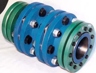
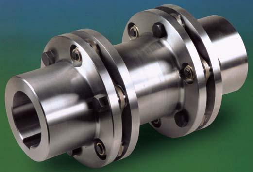

45 RFC RING-flex Torsionally Rigid Disc Couplings RINGFEDER CORPORATION FDC-30-2

 Disc Pack can be Piloted to Hub for Repeatable Balancing per API 671. Fail-safe Hardware Available Fig.")

46 RING-flex Couplings Advantages and Features Accommodate Angular, Axial, and Radial Misalignments Operate Without Wear NO Maintenance or Lubrication High Torsional Rigidity Operate at High Temperatures Long Life All Metal Construction NO Backlash High Torque Capacity Low Restoring Force RING-flex Couplings 6 and 8 bolt disc design Higher Speed Capacities Increased Angular Misalignment Capacity (6 bolt = 1º 1.5º) Disc Pack can be Piloted to Hub for Repeatable Balancing per API 671. Fail-safe Hardware Available Fig. 1 Finite Element Analysis Ringfeder Corporation is very happy to introduce a NEW laminated disc pack, which allows higher misalignments and speed capacities than previous designs. The design was developed through Finite Element Analysis to maximize the allowable misalignment and disc pack life without losing any torque capacity RINGFEDER CORPORATION


47 RING-flex Couplings with Ringfeder Shrink Discs Eliminates ALL Backlash in Hub Connection Eliminates Interference and Press Fit in Hub Connection Allows Axial Flexibility during Assembly Great for Last Minute Timing Between Hubs Eliminates Failures from Poorly Fit Keys WORKING PRINCIPLE Fig. 2 Shrink Disc over hub projection Shrink Discs are external keyless shaft/hub locking devices installed over hub projections. By tightening the locking screws, the locking collars exert radial forces on the tapered inner rings and the hub. After bridging the fit clearances, radial clamping pressure is generated between shaft and hub establishing a solid, frictional connection. For adjustment or removal, just loosen the screws. Fig. 3 RING-flex coupling with Ringfeder Shrink Discs on main drive in environmental test chamber. Fig. 4 RING-flex coupling on fan drive. RING-flex Couplings Unique designs available Ringfeder Corporation has a large engineering staff that specializes in providing unique solutions to your coupling requirements. These solutions can include the following: Flange Mounted Couplings Close-Coupled Couplings Extra Long Couplings Fail-Safe Couplings High Speed Couplings Please call for assistance. RINGFEDER CORPORATION
48 Range and Characteristics Fig. 5 Angular and radial misalignment Axial misalignment SERIES G Applications: Economical design for general purpose use at low and medium speeds with good flexibility and low end thrust. See pages Bolt Design Element Pack consists of individual discs Misalignment Capability angular: K W = 1 per element axial: K a = Double Flexing Single Flexing = K a /2 radial: K R = inches x L where L = distance between disc pack GS - Single Flexing GD - Double Flexing GC - Close Coupled XGS - Single Flexing w/sd XGD - Double Flexing w/sd XGC - Close Coupled w/sd SIZE G 10-4 G 20-4 G 30-4 G 40-4 G 50-4 G 60-4 G 70-4 G 80-4 NOMINAL TORQUE CAPACITY (in-lbs) (Nm) OUTSIDE DIAMETER (inches) (mm) MAX. SPEED UNBALANCED (rpm) AXIAL MISALIGN. +/- K a (inches) (mm) RINGFEDER CORPORATION
49 Range and Characteristics SERIES H Applications: NEW laminated disc pack design for applications requiring higher speeds and greater misalignment capability. See pages 13, 14, 17 and Bolt Design Laminated Disc Pack Misalignment Capability angular: K W = 1.5 per element up to size = 1 per element above size axial: K a = Double Flexing Single Flexing = K a /2 radial: K R = inches x L, up to size inches x L, above size where L = distance between disc pack HS - Single Flexing HD - Double Flexing HC - Close Coupled XHS - Single Flexing w/sd XHD - Double Flexing w/sd SIZE NOMINAL TORQUE CAPACITY (in-lbs) (Nm) OUTSIDE DIAMETER (inches) (mm) MAX. SPEED UNBALANCED (rpm) AXIAL MISALIGN. +/- K a (inches) (mm) RINGFEDER CORPORATION
50 Range and Characteristics SERIES H Applications: NEW laminated disc pack design for applications requiring higher torques and greater misalignment capability. See pages 15, 16, 19 and Bolt Design Laminated Disc Pack Misalignment Capability angular: K W = 0.5 per element axial: K a = Double Flexing Single Flexing = K a /2 radial: K R = inches x L where L = distance between disc pack HS - Single Flexing HD - Double Flexing HC - Close Coupled XHS - Single Flexing w/sd XHD - Double Flexing w/sd SIZE NOMINAL TORQUE CAPACITY (in-lbs) (Nm) OUTSIDE DIAMETER (inches) (mm) MAX. SPEED UNBALANCED (rpm) AXIAL MISALIGN. +/- K a (inches) (mm) RINGFEDER CORPORATION
51 RINGFEDER SHRINK DISC SPECIFICATIONS Shrink Disc Dimensions - Low Inertia Series SHRINK SHAFT RANGE MAX TORQUE CAPACITY D 1 H DISC d w RANGE SIZE M T (inches) (in-lbs) (inches) (inches) (mm) (Nm) (mm) (mm) Hub configuration for Shrink Disc connection Fig. 6 Shrink Disc Dimensions Series RfN SHAFT RANGE MAX TORQUE CAPACITY D 1 H 4071 d w RANGE SIZE M T (inches) (in-lbs) (inches) (inches) (mm) (Nm) (mm) (mm) RfN SHAFT RANGE MAX TORQUE CAPACITY D 1 H 4071 d w RANGE SIZE M T (inches) (in-lbs) (inches) (inches) (mm) (Nm) (mm) (mm) If M T is less than coupling torque capacity, the max Coupling Torque Capacity=M T RINGFEDER CORPORATION
52 SELECTION GUIDE The selection of the coupling size depends entirely on the torque to be transmitted and required shaft sizes. However, for the selection of the coupling type, application conditions (e.g., shaft misalignments, expansions and operating speeds) must be taken into consideration. For any special applications, please consult with us. When selecting a coupling size, make sure that under all operating conditions its torque capacity and speed range are not exceeded. 5. If the RINGFEDER Shrink Disc connection is used, verify that the torque capacity of the Shrink Disc connection does not limit the couplings torque capacity. The Shrink Disc torque capacities for each shaft size can be found on page Use the chart below to verify that your coupling does or does not need to be dynamically balanced. 1. Calculate the driving torque (T AN ) to be transmitted from T AN (in-lbs) = x HP/RPM 2. Determine required coupling Nominal Torque Capacity (T KN ) by finding the appropriate service factor (S M ) in Table 1 for your application. Multiply the torque calculated above (T AN ) by this service factor. T KN (in-lbs) = T AN x S M NOTE: RING-flex Couplings can transmit higher torques for a short period of time without having to consider an additional service factor. Please consult coupling data sheets (pages 10-20) for Maximum Torque values. 3. Check if existing or predicted axial, angular and radial misalignment are within permissible values as shown in the catalog, pages 4-6. If any one of the misalignments is close to the maximum allowable, the maximum misalignment in the other directions and the torque capacity will be effected. For this reason, we recommend selecting a coupling with more misalignment capacity than required. 4. Verify that the maximum hub bore and speed required do not exceed the maximum values for the coupling. NOTE: For a given hub size, larger shafts can be used with the RINGFEDER Shrink Disc than with traditional keyed connections. Fig. 7 Dynamic Balancing Guide Table 1 Service Factor (S m ) Load Uniform Light Shock Medium Shock Heavy Shock Driven Equipment Weight (Kg) Centrifugal Pumps: Conveyors-Evenly Loaded; Alternators; Fans and Blowers- Light Duty; Generators-Evenly Loaded; Mixers-Liquid Centrifugal Pumps; Generators- Pulsating Load; Grinders; Hydraulic Pumps; Machine Tools; Oscillating Pumps, Textile Machinery; Woodworking Machinery Air Compressors-Multi-Cylinder; Cranes; Elevators; Hoists; Punch Presses; Reciprocating Pumps; Ship Drives Air Compressors-Single Cylinder; Dredges; Drilling Rigs; Mining Machinery; Rubber Mixers Driving Equipment Motor or Turbine Reciprocating Engine The service factors listed are intended only as a general guide. For typical service factors used in various applications, refer to AGMA Standard Load Classification and Service Factors for Flexible Couplings (AGMA ) RINGFEDER CORPORATION
53 Selection Example #1 Bore and Keyway: A 60 HP, 4 cylinder diesel engine is to drive a centrifugal pump at 1750 rpm. Both shafts are 1.5 in diameter. Distance between shaft ends is A coupling with (2) Disc Pack is required, because the engine crank shaft and pump shaft are most likely supported by two bearings. Therefore, parallel misalignment between the shafts is possible. 2. Driving Torque: T AN (in-lbs) = x 60 / 1750 = 2160 in-lbs 3.Required Coupling torque capacity based on a S M = 2.0: T KN (in-lbs) = 2160 x (2.0) = 4320 in-lbs Selected Coupling HD 110-6: T KN (in-lbs) = 5090 in-lbs >=4320 in-lbs This coupling can also accommodate the 1750 rpm without dynamic balancing, the 3.5 between shaft ends and the (2) 1.5 shafts. Selection Example #2 Shrink Disc Connection: A 200 HP motor is driving a gearbox at 1750 rpm. This drive is running the transfer system for an automated machining system. The system starts and stops 10 times per minute. Both shaft sizes are 2.5. Distance between shaft ends is A coupling with (2) Disc Pack is required, because the motor and gearbox shafts are most likely both supported by two bearings. Therefore, parallel misalignment between the shafts is possible. 2. Driving Torque: T AN (in-lbs) = x 200 / 1750 = 7200 in-lbs 3. Required Coupling torque capacity based on a S M = 2.0: T KN (in-lbs) = 7200 x (2.0) = in-lbs Selected Coupling XHD 158-6: T KN (in-lbs) = in-lbs > in-lbs This coupling can also accommodate the 1750 rpm without dynamic balancing, and the (2) 2.5 shafts. 4. Select a Shrink Disc for a 2.5 shaft on page 7. Shrink Disc Size: 75 Rfn 4071 Torque Capacity of Shrink Disc = in-lbs This reduces the coupling s maximum torque capacity of in-lbs to in-lbs. Fig With the RINGFEDER Shrink Disc Connection, the 6 distance between shaft ends can be accommodated with the standard double flexing coupling. The shaft needs to be only 1.5 in each hub to ensure a proper Shrink Disc Connection. This gives the coupling the flexibility to have a distance between shafts of 4.88 to is in that range. See Fig. 8. RINGFEDER CORPORATION

 (kg) (kg-m 2 ) (mm) GS 10-4 GS 20-4 GS 30-4 GS 40-4 GS 50-4 GS 60-4 GS 70-4 GS 80-4 Hub = Steel Disc Pack = Stainless Steel Hardware = Steel 3.19 1.25 1.77 1.14 1.97 0.27 4.21 797 1196 4500 2.")


54 SPECIFICATIONS GS Coupling 4 BOLT Fig. 9 COUPLING A D D 3 D 5 L F S 1 L O NOMINAL MAXIMUM MAXIMUM WEIGHT MOMENT AXIAL ANGULAR SIZE max TORQUE TORQUE SPEED OF INERTIA MISALIGN. MISALIGN. CAPACITY CAPACITY UNBALANCED WR 2 +/- K a K w (inches) (inches) (inches) (inches) (inches) (inches) (inches) (in-lbs) (in-lbs) (lbs) (lb-in 2 ) (inches) (mm) (mm) (mm) (mm) (mm) (mm) (mm) (Nm) (Nm) (rpm) (kg) (kg-m 2 ) (mm) GS 10-4 GS 20-4 GS 30-4 GS 40-4 GS 50-4 GS 60-4 GS 70-4 GS 80-4 Hub = Steel Disc Pack = Stainless Steel Hardware = Steel XGS Coupling 4 BOLT with Shrink Disc connection ** Max 'D' is for bores with standard keyways Weight and Moment of Inertia - Assuming maximum bores ** Fig. 10 COUPLING A SHRINK D D 3 D 5 L F S 1 L O NOMINAL MAXIMUM MAXIMUM WEIGHT MOMENT AXIAL SIZE DISC MAX TORQUE TORQUE SPEED OF INERTIA MISALIGN SERIES CAPACITY CAPACITY UNBALANCED WR 2 +/- K a (inches) Rfn 4071 (inches) (inches) (inches) (inches) (inches) (inches) (in-lbs) (in-lbs) (lbs) (lb-in 2 ) (inches) (mm) MAX (mm) (mm) (mm) (mm) (mm) (mm) (Nm) (Nm) (rpm) (kg) (kg-m 2 ) (mm) XGS 10-4 XGS 20-4 XGS 30-4 XGS 40-4 XGS 50-4 XGS 60-4 XGS 70-4 XGS * * Hub = Steel Max 'D' is for bores with Shrink Disc Connection Disc Pack = Stainless Steel Weight and Moment of Inertia - Assuming maximum bores and Shrink Disc Hardware = Steel * Shrink Disc bolts hang over hub end ** For Dimensions D 1 and H please see page RINGFEDER CORPORATION ANGULAR MISALIGN K w
55 SPECIFICATIONS GC Coupling 4 BOLT Fig. 11 COUPLING A D D 3 D 5 L F S 3 L O NOMINAL MAXIMUM MAXIMUM WEIGHT MOMENT AXIAL ANGULAR RADIAL SIZE MAX TORQUE TORQUE SPEED OF INERTIA MISALIGN. MISALIGN. MISALIGN. CAPACITY CAPACITY UNBALANCED WR 2 +/- K a K w K R (inches) (inches) (inches) (inches) (inches) (inches) (inches) (in-lbs) (in-lbs) (lbs) (lb-in 2 ) (inches) PER (inches) (mm) (mm) (mm) (mm) (mm) (mm) (mm) (Nm) (Nm) (rpm) (kg) (kg-m 2 ) (mm) DISC PACK (mm) GC 10-4 GC 20-4 GC 30-4 GC 40-4 GC 50-4 GC 60-4 GC 70-4 GC 80-4 Hub = Steel Spacer = Steel Disc Pack = Stainless Steel Hardware = Steel XGC Coupling 4 BOLT with Shrink Disc connection * Hubs can be shorter upon request - Call Ringfeder Corp. Max 'D' is for bores with standard keyways Weight and Moment of Inertia - Assuming maximum bores * Fig. 12 COUPLING A SHRINK D D 3 D 5 L F S 3 L O NOMINAL MAXIMUM MAXIMUM WEIGHT MOMENT AXIAL ANGULAR RADIAL SIZE DISC MAX TORQUE TORQUE SPEED OF INERTIA MISALIGN. MISALIGN. MISALIGN. SERIES CAPACITY CAPACITY UNBALANCED WR 2 +/- K a K w K R (inches) Rfn 4071 (inches) (inches) (inches) (inches) (inches) (inches) (in-lbs) (in-lbs) (lbs) (lb-in 2 ) (inches) PER (inches) (mm) MAX (mm) (mm) (mm) (mm) (mm) (mm) (Nm) (Nm) (rpm) (kg) (kg-m 2 ) (mm) DISC PACK (mm) XGC XGC XGC XGC XGC XGC XGC XGC Hub = Steel Hubs can be shorter upon request - Call Ringfeder Corp. Spacer = Steel Max 'D' is for bores with Shrink Disc Connection Disc Pack = Stainless Steel Weight and Moment of Inertia - Assuming maximum bores and Shrink Disc Hardware = Steel * For Dimensions D 1 and H please see page 7 RINGFEDER CORPORATION

 (mm) (mm) (mm) (Nm) (Nm) (rpm) (kg) (kg-m 2 ) (mm) DSIC PACK (mm) GD 10-4 GD 20-4 GD 30-4 GD 40-4 GD 50-4 GD 60-4 GD 70-4 GD 80-4 Hub = Steel Spacer = Steel Disc Pack = Stainless Steel Hardware")


56 SPECIFICATIONS GD Coupling 4 BOLT Fig. 13 COUPLING A D D 3 D 5 L F S 1 S 3 L O NOMINAL MAXIMUM MAXIMUM WEIGHT MOMENT AXIAL ANGULAR RADIAL SIZE MAX TORQUE TORQUE SPEED OF INERTIA MISALIGN. MISALIGN. MISALIGN. CAPACITY CAPACITY UNBALANCED WR 2 +/- K a K w K R (inches) (inches) (inches) (inches) (inches) (inches) (inches) (inches) (in-lbs) (in-lbs) (lbs) (lb-in 2 ) (inches) PER (inches) (mm) (mm) (mm) (mm) (mm) (mm) (mm) (mm) (Nm) (Nm) (rpm) (kg) (kg-m 2 ) (mm) DSIC PACK (mm) GD 10-4 GD 20-4 GD 30-4 GD 40-4 GD 50-4 GD 60-4 GD 70-4 GD 80-4 Hub = Steel Spacer = Steel Disc Pack = Stainless Steel Hardware = Steel XGD Coupling 4 BOLT with Shrink Disc connection Max 'D' is for bores with standard keyways Weight and Moment of Inertia - Assuming maximum bores ** ** Fig. 14 COUPLING A SHRINK D D 3 D 5 L F S 1 S 3 L O NOMINAL MAXIMUM MAXIMUM WEIGHT MOMENT AXIAL ANGULAR RADIAL SIZE DISC MAX TORQUE TORQUE SPEED OF INERTIA MISALIGN. MISALIGN. MISALIGN. SERIES CAPACITY CAPACITY UNBALANCED WR 2 +/- K a K w K R (inches) Rfn 4071 (inches) (inches) (inches) (inches) (inches) (inches) (inches) (in-lbs) (in-lbs) (lbs) (lb-in 2 ) (inches) PER (inches) (mm) Max (mm) (mm) (mm) (mm) (mm) (mm) (mm) (Nm) (Nm) (rpm) (kg) (kg-m 2 ) (mm) DISC PACK (mm) XGD 10-4 XGD 20-4 XGD 30-4 XGD 40-4 XGD 50-4 XGD 60-4 XGD 70-4 XGD * * Hub = Steel Max 'D' is for bores with Shrink Disc Connection Spacer = Steel Weight and Moment of Inertia - Assuming maximum bores and Shrink Disc Disc Pack = Stainless Steel * Shrink Disc bolts hang over hub end Hardware = Steel ** For Dimensions 'D1' and 'H' please see page RINGFEDER CORPORATION
57 SPECIFICATIONS HS Coupling 6 BOLT Fig. 15 COUPLING A D D 3 L F S 1 L O NOMINAL MAXIMUM MAXIMUM WEIGHT MOMENT AXIAL ANGULAR SIZE MAX TORQUE TORQUE SPEED OF INERTIA MISALIGN. MISALIGN. CAPACITY CAPACITY UNBALANCED WR 2 +/- K a K w (inches) (inches) (inches) (inches) (inches) (inches) (in-lbs) (in-lbs) (lbs) (lb-in 2 ) (inches) (mm) (mm) (mm) (mm) (mm) (mm) (Nm) (Nm) (rpm) (kg) (kg-m 2 ) (mm) HS HS HS HS -6 HS HS HS HS HS HS HS HS HS HS HS HS Hub = Steel Disc Pack = Stainless Steel Hardware = Steel Max 'D' is for bores with standard keyways Weight and Moment of Inertia - Assuming maximum bores RINGFEDER CORPORATION
58 SPECIFICATIONS XHS Coupling 6 BOLT with Shrink Disc connection * * Fig. 16 COUPLING A SHRINK D D 3 L F S 1 L O NOMINAL MAXIMUM MAXIMUM WEIGHT MOMENT AXIAL ANGULAR SIZE DISC MAX TORQUE TORQUE SPEED OF INERTIA MISALIGN. MISALIGN. SERIES CAPACITY CAPACITY UNBALANCED WR 2 +/- K a K w (inches) Rfn 4071 (inches) (inches) (inches) (inches) (inches) (in-lbs) (in-lbs) (lbs) (lb-in 2 ) (inches) (mm) MAX (mm) (mm) (mm) (mm) (mm) (Nm) (Nm) (rpm) (kg) (kg-m 2 ) (mm) XHS XHS XHS XHS -6 XHS XHS XHS XHS XHS XHS XHS XHS XHS XHS XHS XHS Hub = Steel Max 'D' is for bores with Shrink Disc Connection Disc Pack = Stainless Steel Weight and Moment of Inertia - Assuming maximum bores and Shrink Disc Hardware = Steel * For Dimensions 'D1' and 'H' please see page RINGFEDER CORPORATION
59 SPECIFICATIONS HS Coupling 8 BOLT Fig. 17 COUPLING A D D 3 L F S 1 L O NOMINAL MAXIMUM MAXIMUM WEIGHT MOMENT AXIAL ANGULAR SIZE MAX TORQUE TORQUE SPEED OF INERTIA MISALIGN. MISALIGN. CAPACITY CAPACITY UNBALANCED WR 2 +/- K a K w (inches) (inches) (inches) (inches) (inches) (inches) (in-lbs) (in-lbs) (lbs) (lb-in 2 ) (inches) (mm) (mm) (mm) (mm) (mm) (mm) (Nm) (Nm) (rpm) (kg) (kg-m 2 ) (mm) HS HS HS HS HS HS HS HS HS HS HS HS HS HS HS HS HS Hub = Steel Disc Pack = Stainless Steel Hardware = Steel WEIGHTS AND INERTIAS AVAILABLE UPON REQUEST Max 'D' is for bores with standard keyways Weight and Moment of Inertia - Assuming maximum bores RINGFEDER CORPORATION
60 SPECIFICATIONS XHS Coupling 8 BOLT with Shrink Disc connection * * Fig. 18 COUPLING A SHRINK D D 3 L F S 1 L O NOMINAL MAXIMUM MAXIMUM WEIGHT MOMENT AXIAL ANGULAR SIZE DISC MAX TORQUE TORQUE SPEED OF INERTIA MISALIGN. MISALIGN. SERIES CAPACITY CAPACITY UNBALANCED WR 2 +/- K a K w (inches) Rfn 4071 (inches) (inches) (inches) (inches) (inches) (in-lbs) (in-lbs) (lbs) (lb-in 2 ) (inches) (mm) MAX (mm) (mm) (mm) (mm) (mm) (Nm) (Nm) (rpm) (kg) (kg-m 2 ) (mm) XHS XHS XHS XHS XHS XHS XHS XHS XHS XHS XHS XHS XHS XHS XHS XHS XHS Hub = Steel Max 'D' is for bores with Shrink Disc Connection Disc Pack = Stainless Steel Weight and Moment of Inertia - Assuming maximum bores and Shrink Disc Hardware = Steel * For Dimensions 'D1' and 'H' please see page 7 WEIGHTS AND INERTIAS AVAILABLE UPON REQUEST RINGFEDER CORPORATION
61 SPECIFICATIONS HD Coupling 6 BOLT Fig. 19 COUPLING A D D 3 L F S 1 S 3 L O NOMINAL MAXIMUM MAXIMUM WEIGHT MOMENT AXIAL ANGULAR RADIAL SIZE MAX TORQUE TORQUE SPEED OF INERTIA MISALIGN MISALIGN. MISALIGN. CAPACITY CAPACITY UNBALANCED WR 2 +/- K a K w K R (inches) (inches) (inches) (inches) (inches) (inches) (inches) (in-lbs) (in-lbs) (lbs) (lb-in 2 ) (inches) PER (inches) (mm) (mm) (mm) (mm) (mm) (mm) (mm) (Nm) (Nm) (rpm) (kg) (kg-m 2 ) (mm) DISC PACK (mm) HD HD HD HD -6 HD HD HD HD HD HD HD HD HD HD HD HD Hub = Steel Spacer = Steel Disc Pack = Stainless Steel Hardware = Steel Max 'D' is for bores with standard keyways Weight and Moment of Inertia - Assuming maximum bores RINGFEDER CORPORATION
62 SPECIFICATIONS XHD Coupling 6 BOLT with Shrink Disc connection * * Fig. 20 COUPLING A SHRINK D D 3 L F S 1 S 3 L O NOMINAL MAXIMUM MAXIMUM WEIGHT MOMENT AXIAL ANGULAR RADIAL SIZE DISC MAX TORQUE TORQUE SPEED OF INERTIA MISALIGN MISALIGN. MISALIGN. SERIES CAPACITY CAPACITY UNBALANCED WR 2 +/- K a K w K R (inches) Rfn 4071 (inches) (inches) (inches) (inches) (inches) (inches) (in-lbs) (in-lbs) (lbs) (lb-in 2 ) (inches) PER (inches) (mm) MAX (mm) (mm) (mm) (mm) (mm) (mm) (Nm) (Nm) (rpm) (kg) (kg-m 2 ) (mm) DISC PACK (mm) XHD XHD XHD XHD XHD XHD XHD XHD XHD XHD XHD XHD XHD XHD XHD XHD Hub = Steel Max 'D' is for bores with Shrink Disc Connection Spacer = Steel Weight and Moment of Inertia - Assuming maximum bores and Shrink Disc Disc Pack = Stainless Steel Hardware = Steel * For Dimensions 'D1' and 'H' please see page RINGFEDER CORPORATION
63 SPECIFICATIONS HD Coupling 8 BOLT Fig. 21 COUPLING A D D 3 L F S 1 S 3 L O NOMINAL MAXIMUM MAXIMUM WEIGHT MOMENT AXIAL ANGULAR RADIAL SIZE MAX TORQUE TORQUE SPEED OF INERTIA MISALIGN MISALIGN. MISALIGN. CAPACITY CAPACITY UNBALANCED WR 2 +/- K a K w K R (inches) (inches) (inches) (inches) (inches) (inches) (inches) (in-lbs) (in-lbs) (lbs) (lb-in 2 ) (inches) PER (inches) (mm) (mm) (mm) (mm) (mm) (mm) (mm) (Nm) (Nm) (rpm) (kg) (kg-m 2 ) (mm) DISC PACK (mm) HD HD HD HD HD HD HD HD HD HD HD HD HD HD HD HD HD Hub = Steel Spacer = Steel Disc Pack = Stainless Steel Hardware = Steel Max 'D' is for bores with standard keyways Weight and Moment of Inertia - Assuming maximum bores RINGFEDER CORPORATION
64 SPECIFICATIONS XHD Coupling 8 BOLT with Shrink Disc connection * * Fig. 22 COUPLING A SHRINK D D 3 L F S 1 S 3 L O NOMINAL MAXIMUM MAXIMUM WEIGHT MOMENT AXIAL ANGULAR RADIAL SIZE DISC MAX TORQUE TORQUE SPEED OF INERTIA MISALIGN. MISALIGN. MISALIGN. SERIES CAPACITY CAPACITY UNBALANCED WR 2 +/- K a K w K R (inches) Rfn 4071 (inches) (inches) (inches) (inches) (inches) (inches) (in-lbs) (in-lbs) (lbs) (lb-in 2 ) (inches) PER (inches) (mm) MAX (mm) (mm) (mm) (mm) (mm) (mm) (Nm) (Nm) (rpm) (kg) (kg-m 2 ) (mm) DISC PACK (mm) XHD XHD XHD XHD XHD XHD XHD XHD XHD XHD XHD XHD XHD XHD XHD XHD XHD Hub = Steel Max 'D' is for bores with Shrink Disc Connection Spacer = Steel Weight and Moment of Inertia - Assuming maximum bores and Shrink Disc Disc Pack = Stainless Steel Hardware = Steel * For Dimensions 'D1' and 'H' please see page RINGFEDER CORPORATION
65 RING-flex Coupling Installation Instructions TOOLS REQUIRED: Torque Wrench and Sockets for Shrink Disc and Coupling Hex Bolts (see Tables 2,3 and 4) Open end wrench for Coupling Hex Bolts Straight Edge and/or Dial Indicator Feeler Gauges THESE INSTRUCTIONS ARE FOR THE STAN- DARD SERIES COUPLINGS WITH NORMAL RUN- NING CONDITIONS. SPECIAL COUPLING DESIGNS MAY HAVE DIFFERENT INSTRUCTIONS. It is recommended to disassemble the coupling for easier installation. Note Figures for the correct arrangement of the bolts, washers, disc pack, and nuts. Attachment to the Shaft Shrink Disc 1. Inspect both driving and driven shafts making sure they are clean and free from burrs. Lightly oil shaft and hub bore. DO NOT USE MOLYKOTE OR SIMILAR LUBRICANTS. 2. Place first hub with Shrink Disc on one shaft and the second hub on the other shaft. Slide them back so that both shaft ends are visible. 3. Move first hub to be flush with shaft end. Gradually tighten all Shrink Disc locking screws, in several passes, to specified tightening torque (M A ); see Tables 2 and 3. Shrink Disc is not fully installed until one pass is completed without any bolts turning. Use Torque Wrench! For in-depth instructions, see catalog W Follow instructions for axial alignment and then fit second hub to shaft as explained in Step 3. Table 2 Shrink Disc Bolt Information, Low Inertia Series SHRINK M A SOCKET DISC (in-lbs) SIZE SIZE (Nm) (mm) Table 3 Shrink Disc Bolt Information RfN M A SOCKET RfN M A SOCKET 4071 (ft-lbs) SIZE 4071 (ft-lbs) SIZE SIZE (Nm) (mm) SIZE (Nm) (mm) RINGFEDER CORPORATION
66 Installation Instructions, cont. Attachment to the Shaft Bore and Keyway 1. Inspect shaft and hub bores and keyways to make sure that they are clean and free of burrs. Lightly oiling the shaft will also make it easier to assemble. 2. Place first hub on one shaft and second hub on the second shaft. Slide them until shaft ends are visible. 3. Hubs are supplied standard with a slight clearance fit. Interference fits would be recommended for bores larger than 3. For more information, please contact Ringfeder. 4. Move hubs to be flush with end of the shaft. Hubs will last longest when the key is engaged for the full length of the hub. 5. Fit key into hub and turn set screw until top of key is contacted in the hub. 6. Follow instructions for axial alignment and then secure second hub to shaft as explained in Steps 4 and 5. MACHINERY ALIGNMENT The life of the coupling is directly affected by the alignment accuracy between the two coupling halves. Careful initial alignment will permit the coupling to operate at full capacity and allow for some future operational misalignments (i.e. equipment settling). For this reason, the maximum misalignment values given in the next tables are 30% of the maximum values for the coupling. Keeping all three directions of misalignment within these limits will increase the coupling life. Axial Alignment 1. Bring equipment into the best visual alignment possible. Position the hubs axially so that the distance between shaft ends is within min. and max. dimensions S 1 (Single Flexing) and S 3 (Double Flexing) for standard couplings. See Figures 23, 24 and Table 4. For non-standard couplings, check corresponding coupling drawing. 2. Now locate first hub so that the shaft end is flush with the hub face and lock into place. Please see pertinent Attachment to the Shaft instructions. 3. Move second hub into position axially using the S 1 (Single Flexing) or S 3 (Double Fig. 23 Single Flexing Fig. 24 Double Flexing * X is valid with the Shrink Disc Shaft/Hub Connection only. Flexing), X, and Tolerance for standard couplings. See Figures 23, 24 and Table Proceed with locking second hub to the shaft by following the pertinent Attachment to the Shaft instructions. Angular Alignment 1. With a dial indicator measure the angular misalignment by determining the parallelism of the coupling flange faces. 2. Dimension (U) as shown in Figure 25 should be measured in at least three points, equally spaced, to determine maximum value for (U). This must not exceed the max. allowable dimension stated in Table Adjust or shim equipment to bring indicator reading within max. allowable angular misalignment (U). Fig RINGFEDER CORPORATION
67 Installation Instructions, cont. Parallel (Radial) Alignment 1. Initial parallel alignment can be checked by using a straight-edge across the hub flanges (per Fig. 26) to measure the approx. distance (r) as shown in Table 4 and Fig. 26. A more precise method is using the dial indicator whereby the parallel off-set is measured in at least two places 90 degrees apart while rotating one hub. This is shown in Fig Adjust or shim equipment to bring indicator reading within max. allowable parallel misalignment (r) per Table It is a good practice to check the coupling alignment one last time after completing the assembly. This can be achieved by measuring the disc pack gap in 2 locations 180 degrees apart to find (2) lengths. The difference in these two measurements should not exceed (U); see Table 4. This completes the coupling installation. CAUTION: All rotating eqiupment is potentially dangerous and must be properly guarded. It is the user s responsibility to check for all applicable safety codes and provide suitable guards and protection. Fig. 26 Fig. 29 G Series Hardware Arrangement Fig. 27 Fig. 30 H Series Hardware Arrangement Installing Disc Pack and Sleeve 1. Once the hubs are aligned in the axial, angular and parallel directions, install the disc pack and sleeve. Figures 29 and 30 show the hardware orientation for each coupling type. PLEASE NOTE: It is very important on the Series G couplings to position the washers with the rounded face towards the disc pack. 2. At this point, the coupling bolts should be torqued to specified torque value (T); see Table 4. A torque wrench should be used to assure proper bolt tightening. PLEASE NOTE: With the Series G coupling, it is recommended to always turn the nut and hold the bolt head. RINGFEDER CORPORATION
68 Installation Instructions, cont. Table 4 S 1 S 3 X +/- U r T Hex or (inches) (inches) (inches) (inches) (inches) (inches) (ft-lbs) Socket (mm) (mm) (mm) (mm) (mm) (mm) (Nm) Size Bolt Series G Axial Alignment Angular Parallel Information S 1 S 3 X +/- U r T Hex or (inches) (inches) (inches) (inches) (inches) (inches) (ft-lbs) Socket (mm) (mm) (mm) (mm) (mm) (mm) (Nm) Size Series H Bolt 6 Bolt Axial Alignment Angular Parallel Information /16" /2" /2" /8" /4" /4" /16" /16" mm mm mm mm mm mm mm mm mm mm mm mm mm S 1 S 3 X +/- U r T Hex or (inches) (inches) (inches) (inches) (inches) (inches) (ft-lbs) Socket (mm) (mm) (mm) (mm) (mm) (mm) (Nm) Size Series H Bolt 8 Bolt Axial Alignment Angular Parallel Information mm mm mm mm mm mm Table 5 Standard Bore Tolerances Bore Diameter (inches) Tolerance (inches) over to / / / / / / RINGFEDER CORPORATION
69 TYPICAL COUPLING CONFIGURATIONS Fig. 31 Double Flexing Fig. 32 Double flexing with larger hub for larger shaft diameter. Fig. 33 Double flexing mounted with Shrink Discs for absolutely backlash-free shaft-hub connection and axial adjustment capability. Fig. 34 Full-floating shaft coupling with tubular spacer. Fig. 35 Single Flexing Fig single flexing couplings with a solid intermediate shaft. Fig. 37 Flange coupling for connection to engine flywheel or fluid couplings. Fig. 38 Vertical installation requires a support for the weight of the spacer. Fig. 39 Full-floating and semi-floating shaft couplings with pillow blocks to bridge large spaces between driving and driven equipment. RINGFEDER CORPORATION


70 MORE COUPLING CONFIGURATIONS Fig. 40 Double flexing coupling mounted with Half Shrink Discs Fig. 41 Single flexing coupling mounted with one Shrink Disc and one internal Locking Assembly. Fig. 42 Single flexing coupling fastened with two internal Locking Assemblies Fig. 43 Double flexing coupling with extended spacer mounted with two internal Locking Assemblies. Fig. 44 Two single flexing couplings with Shrink Discs for accommodation of varying floating shaft lengths. Fig. 45 Double flexing coupling fastened with a Shrink Disc on one side and a key with a set screw on the other. Fig. 46 Single flexing coupling fastened with Ringfeder Locking elements. Fig. 47 Double-double flexing coupling for test stand RINGFEDER CORPORATION


, 98 Sh. A (red), 64 Sh. D (green), 80 Sh.")
71 WE ALSO OFFER: TRASCO ES: backlash free couplings The main design function of the TRASCO ES coupling is to transmit motion while absorbing misalignments and vibrations, with absolute precision and without any backlash whatsoever. The very compact design makes it a very rational and functional device ideal in every positioning or feedback application. Description The TRASCO ES consists of two hubs, made of highstrength aluminum (up to the 38/45 size) or steel (from size 42) that are connected with an elastic element. The hubs are made by accurate machining, in order to achieveaccuracy, balance and optimal concentricity. The spiders are made of a special polyurethane mixture that was developed after considerable research and laboratory testing. They are press-formed by a process which guarantees a highdegree of dimensional accuracy. The spiders are available in different hardnesses: 92 Sh. A (yellow), 98 Sh. A (red), 64 Sh. D (green), 80 Sh. A (blue). Coupling performance depends on the type of spider selected. Other hardnesses are available on request to meet special operating conditions, such as higher temperatures, higher torques, and higher degree of vibrationdamping capability. Operation When the polyurethane element is installed in the precision machined hub it becomes precompressed, thereby providing the zero backlash feature which characterizes the transmission performance of this coupling. The coupling remains torsionally rigid (and backlash free) within the range of the pre-compression load, while permitting the absorption of radial, angular and axial misalignments as well as undesired vibrations. The significantly wide pre-compressed area of the flexible element keeps the contact pressure low against the elastic element. Therefore, the spider s jaws, can be overloaded many times without losing original properties. Advantages Backlash free torque transmission Vibration dampening Low inertia Easy and time saving assembly Maintenance free High speed performance Electrical isolation In all positioning and feedback applications, smaller TRASCO ES couplings (up to size 19/24) replace successfully bellows, oldham, metallic beam and disc couplings. Larger TRASCO ES couplings (from size 24/28) replace successfully metal disc, rigid, steel gear and beam coupling in spindle drives, process line drives and other high torque drive applications. Main applications Encoders Steppers Pulse generators Tachometers Medical equipment Robotics Servos Ball screws Machine tools spindles Process lines Operating Temperature Range The recommended operating temperature range for the TRASCO ES is between 40 and +90 C. Peak temperatures as high as 120 C can be tolerated. Higher operating temperatures may cause the spider to lose a considerable amount of elasticity, thus substantially lowering the torque capacity. REQUEST A CATALOG TODAY! RINGFEDER CORPORATION


72 RFC SPECIALTY PRODUCTS RfC Specialty Locking Devices Ringfeder Corporation excels at specialty keyless shaft/hub connection solutions. From 1/4" shafts to 30" shafts, our engineers have the solution. BALL DETENT TORQUE LIMITERS Type BD These accurate ball/roller and socket torque limiters are easily adjustable for different torque settings. In the event of an overload, personnel and equipment are protected as these devices disconnect mechanically and make contact with a limit switch that sounds an alarm or otherwise shuts the drive down. Available in various configurations and combinations with couplings. FRICTION TORQUE LIMITER Type FC Easily adjustable, these torque limiters rely on friction to transmit the set torque. When an overload occurs, these devices slip until the overload is removed or the machine is reset. Available in various configurations and combinations with couplings. ARCUSAFLEX Flywheel Couplings Highly flexible, backlash-free, vulcanized rubber disc couplings designed to couple the flywheel of an internal combustion engine to the shaft of the driven machine. Rubber disc element accepts relatively high angular, axial and parallel misalignments. Flange dimensions according to SAE J620 standards. Multi Mont OCTA Flywheel Couplings Torsionally flexible, economical flange couplings for connecting the flywheel of a combustion engine to the input shaft of a driven machine. Rubber elements dampen vibrations and accommodate misalignments. In accordance with our established policy to constantly improve our products, the specifications contained herein are subject to change without notice. Since our Engineers cannot be aware of all applications and cannot control all the factors that may affect the function of our products, our warranty applies to our products only. TECHNICAL ASSISTANCE Call us Toll Free at Please let us know what your specific requirements are and we shall be very happy to work out detailed recommendations without any obligation. Just send a sketch with your requirements and specifications. Call or write for more information Visit our website: Our Representative: RINGFEDER CORPORATION 165 Carver Avenue P.O. Box 691 Westwood, N.J TEL (201) FAX (201) Los Angeles Office: Tel (805) FAX (805) RINGFEDER CORPORATION Copyright /2004 FDC-30-2 Printed in U.S.A.

73 RINGFEDER Corporation Power Transmission Solutions INTRODUCING... the next generation of taper bushing system by RFC! RING-lok TM TAPER BUSHING SYSTEM NEW from Ringfeder Corporation. TAPER BUSHING SIZES: in shaft sizes from 12mm to 70mm Now have the functionality of a keyless locking device in a taper bushing system. NO backlash! NO keys to fit! Works in cast iron and steel hubs, anywhere the traditional taper bushing system is used V Belt pulleys, timing pulleys, couplings, sprockets, sheaves, etc. Impervious to reversing loads, not susceptible to vibrating loose, the RFC RING-lok TM system is manufactured from high grade steel to exacting quality standards. Available from stock in metric sizes (inch sizes upon request for the moment) for the taper bushing sizes listed on the left. RINGFEDER CORPORATION RL-1
74 RING-lok TM DIMENSION TABLES d= Nominal RING-lok I.D. ( Shaft O.D.) D= RING-lok Outside Diameter H= Taper Bushing Length H 1 = Length Through Bore, Relaxed Condition H 2 = Overall Length M t = Maximum Transmissible Torque P ax = Transmissible Axial Load (Thrust Capacity) M a = Required Tightening Torque per Bolt M s = Required Tightening Torque per Set Screw S= Required Hex Key Size T 1 = Machining Tolerances on Shaft (d) How to Order: Specify RING-lok Type and bore. Example Metric: Type 1108 with 22mm bore: RL1108d22 Example Inch: Type 1108 with 3/4 bore RL1108d0.75 Notes: Inch sizes only upon request Table 1 RING-lok TM Type Units Dimensions Bolts** Nm / lb-ft Set Screws Nm / lb-ft d max D H H 1 H 2 Qty Size M a S Qty Size M s S 1108 Metric - mm Inch M / Metric - mm Inch M / Metric - mm Inch M / Metric - mm Inch M / Metric - mm Inch M /2* /4" 3020 Metric - mm Inch M / * All set screws Metric (BSW) except for Type 2517 which is 1/2". ** All locking bolts are Metric RING-lok TM 1108 Shaft Size Tolerance Performance Model Units Nm / lb-ft N / lbs Number d T 1 M t P ax Metric - mm 12 +0/ ,300 RL1108d12 Inch / ,765 Metric - mm 14 +0/ ,500 RL1108d14 Inch / ,035 Metric - mm 15 +0/ ,000 RL1108d15 Inch / ,147 Metric - mm 16 +0/ ,500 RL1108d16 Inch / ,260 Metric - mm 18 +0/ ,000 RL1108d18 Inch / ,923 Metric - mm 19 +0/ ,900 RL1108d19 Inch / ,900 Metric - mm 20 +0/ ,400 RL1108d20 Inch / ,013 Metric - mm 22 +0/ ,400 RL1108d22 Inch / ,237 RING-lok TM 1210 Shaft Size Tolerance Performance Model Units Nm / lb-ft N / lbs Number d T 1 M t P ax Metric - mm 14 +0/ ,400 RL1210d14 Inch / ,710 Metric - mm 15 +0/ ,000 RL1210d15 Inch / ,845 Metric - mm 16 +0/ ,200 RL1210d16 Inch / ,890 Metric - mm 18 +0/ ,700 RL1210d18 Inch / ,778 Metric - mm 19 +0/ ,100 RL1210d19 Inch / ,868 Metric - mm 20 +0/ ,400 RL1210d20 Inch / ,710 Metric - mm 22 +0/ ,500 RL1210d22 Inch / ,958 Metric - mm 24 +0/ ,700 RL1210d24 Inch / ,228 Metric - mm 25 +0/ ,200 RL1210d25 Inch / , RINGFEDER CORPORATION
75 RING-lok TM 1610 RING-lok TM 2012 Model Number RL1610d14 RL1610d15 RL1610d16 RL1610d18 RL1610d19 RL1610d20 RL1610d22 RL1610d24 RL1610d25 RL1610d28 RL1610d30 RL1610d32 RL1610d35 Shaft Size Tolerance Performance Units Nm / lb-ft N / lbs d T 1 M t P ax Metric - mm 14 +0/ ,000 Inch / ,946 Metric - mm 15 +0/ ,700 Inch / ,103 Metric - mm 16 +0/ ,300 Inch / ,238 Metric - mm 18 +0/ ,700 Inch / ,553 Metric - mm 19 +0/ ,400 Inch / ,486 Metric - mm 20 +0/ ,000 Inch / ,621 Metric - mm 22 +0/ ,200 Inch / ,890 Metric - mm 24 +0/ ,500 Inch / ,183 Metric - mm 25 +0/ ,100 Inch / ,317 Metric - mm 28 +0/ ,900 Inch / ,598 Metric - mm 30 +0/ ,800 Inch / ,800 Metric - mm 32 +0/ ,100 Inch / ,868 Metric - mm 35 +0/ ,800 Inch / ,250 Model Number RL2012d19 RL2012d20 RL2012d22 RL2012d24 RL2012d25 RL2012d28 RL2012d30 RL2012d32 RL2012d35 RL2012d38 RL2012d40 RL2012d42 Shaft Size Tolerance Performance Units Nm / lb-ft N / lbs d T 1 M t P ax Metric - mm 19 +0/ ,900 Inch / ,172 Metric - mm 20 +0/ ,700 Inch / ,352 Metric - mm 22 +0/ ,100 Inch / ,666 Metric - mm 24 +0/ ,400 Inch / ,959 Metric - mm 25 +0/ ,100 Inch / ,868 Metric - mm 28 +0/ ,200 Inch / ,689 Metric - mm 30 +0/ ,300 Inch / ,487 Metric - mm 32 +0/ ,500 Inch / ,307 Metric - mm 35 +0/ ,000 Inch / ,644 Metric - mm 38 +0/ ,800 Inch / ,049 Metric - mm 40 +0/ ,100 Inch / ,341 Metric - mm 42 +0/ ,500 Inch / ,656 RING-lok TM 2517 RING-lok TM 3020 Model Number RL2517d24 RL2517d25 RL2517d28 RL2517d30 RL2517d32 RL2517d35 RL2517d38 RL2517d40 RL2517d42 RL2517d45 RL2517d48 RL2517d50 RL2517d55 Shaft Size Tolerance Performance Units Nm / lb-ft N / lbs d T 1 M t P ax Metric - mm 24 +0/ ,000 Inch / ,667 Metric - mm 25 +0/ ,900 Inch / ,870 Metric - mm 28 +0/ ,900 Inch / ,319 Metric - mm 30 +0/ ,800 Inch / ,746 Metric - mm 32 +0/ ,500 Inch / ,679 Metric - mm 35 +0/ ,000 Inch / ,466 Metric - mm 38 +0/ ,800 Inch / ,646 Metric - mm 40 +0/ ,200 Inch / ,960 Metric - mm 42 +0/ ,600 Inch / ,477 Metric - mm 45 +0/ ,300 Inch / ,859 Metric - mm 48 +0/ ,600 Inch / ,151 Metric - mm 50 +0/ ,100 Inch / ,488 Metric - mm 55 +0/ ,900 Inch / ,893 Model Number RL3020d35 RL3020d38 RL3020d40 RL3020d42 RL3020d45 RL3020d48 RL3020d50 RL3020d55 RL3020d60 RL3020d65 RL3020d70 Shaft Size Tolerance Performance Units Nm / lb-ft N / lbs d T 1 M t P ax Metric - mm 35 +0/ ,100 Inch / ,458 Metric - mm 38 +0/ ,400 Inch / ,975 Metric - mm 40 +0/ ,000 Inch / ,335 Metric - mm 42 +0/ ,500 Inch / ,672 Metric - mm 45 +0/ ,900 Inch / ,211 Metric - mm 48 +0/ ,200 Inch / ,728 Metric - mm 50 +0/ ,800 Inch / ,088 Metric - mm 55 +0/ ,000 Inch / ,435 Metric - mm 60 +0/ ,400 Inch 2. +0/ ,200 Metric - mm 65 +0/ ,700 Inch / ,942 Metric - mm 70 +0/ ,100 Inch / ,706 RINGFEDER CORPORATION
. 3. Position the component on the shaft in the required position. 4.")

: 3. Once the inner ring is loose, loosen the two set screws. 4.")
76 RING-lok TM TAPER BUSHING SYSTEM ASSEMBLY Assembly is extremely simple and fast: 1. Couple the RING-lok TM bushing to the hub by means of the two set screws. 2. Gradually tighten the set screws, S, until the torque, M s, is achieved (see Table 1). 3. Position the component on the shaft in the required position. 4. Then tighten the clamping screws gradually and evenly in a diametrically opposite pattern until the torque, M a, is also reached (see Table 1). NOTE: It is not necessary or advisable to lubricate the RING-lok TM bushing. NEVER use any anti-sieze lubricants on the shaft with any Ringfeder locking devices. DISASSEMBLY To remove the RING-lok TM bushing: 1. Loosen the tightening screws and insert them into the threaded disassembly holes. 2. Tighten the screws until the tapered bushing is released. To remove the bushing outer ring (if necessary): 3. Once the inner ring is loose, loosen the two set screws. 4. Keeping the loosened set screws in place, re-position the inner bushing ring so that it is rotated 60 degrees from the original position. The inner ring flange now leans on the two set screws and the six (6) through holes in the flange are now positioned in line with the six (6) tapped holes of the outer ring. 5. Insert the screws and tighten them gradually until the outer ring is released. In accordance with our established policy to constantly improve our products, the specifications contained herein are subject to change without notice. Since our Engineers cannot be aware of all applications and cannot control all the factors that may affect the function of our products, our warranty applies to our products only. TECHNICAL ASSISTANCE Call us Toll Free at Please let us know what your specific requirements are and we shall be very happy to work out detailed recommendations without any obligation. Just send a sketch with your requirements and specifications. Call or write for more information. Visit our website: Our Representative: RINGFEDER CORPORATION 165 Carver Avenue P.O. Box 691 Westwood, NJ TEL (201) FAX (201) Los Angeles Office: TEL (805) FAX (805) Copyright 2000 RL-1 3/2002 Printed in U.S.A.
RFC SPECIALTY LOCKING DEVICES
 RINGFEDER Products are available from MARYLAND METRICS P.O. Box 261 Owings Mills, MD 21117 USA email: sales@mdmetric.com web: http://mdmetric.com phones: (410)358-3130 (800)638-1830 faxes: (410)358-3142
TRADITIONAL SHAFT HUB CONNECTIONS
 TABLE OF CONTENTS MAV locking devices.... Pg. 2 Traditional shaft hub connections...pg. 3 Advantages of MAV locking devices...pg. 4 The wedge principle..... Pg. 5 Installation removal...pg. 6 Characteristics....
Locking Assemblies & Locking Elements
 US 12 2010 Locking Assemblies & Locking Elements Partner for performance www.ringfeder.com A Global Presence For You The RINGFEDER POWER TRANSMISSION GMBH was founded in 1922 in Krefeld, Germany to fabricate
TSUBAKI POWER TRANSMISSION COMPONENTS
 TSUBAKI POWER TRANSMISSION COMPONENTS Contents Page Introduction to Shock Relays F-2 "SS" Series Analogue Shock Relays F-3 - F-5 "SD" Series Digital Shock Relays F-6 - F-10 Introduction to F-11 AS Construction/Selection/Installation/Removal
Shrink Discs, Smart-Lock & Shaft Couplings
 RINGFEDER Products are available from MARYLAND METRICS Shrink Discs, Smart-Lock & Shaft Couplings US 08 2009 Partner for performance RINGFEDER Products are available from MARYLAND METRICS P.O. Box 261
SIT-LOCK self locking elements
 self locking elements Advantages of on the shaft-hub connection compared with traditional systems Easy assembly and disassembly Both actions take place by locking and unlocking the clamping screws with
Shaft-Hub-Connections
 Stand: 14.01.2010 Shaft-Hub-Connections Shrink Discs Cone Clamping Elements Star Discs 36 Edition 2012/2013 RINGSPANN Eingetragenes Warenzeichen der RINGSPANN GmbH, Bad Homburg Table of Contents Introduction
For advanced drive technology CLAMPEX. Shaft-Hub-Connection. KTR Precision Joints CLAMPEX
 technology CLAMPEX Shaft-Hub-Connection CLAMPEX KTR Precision Joints 07 technology Table of contents Page Brief information 09 Selection and calculation -5 CLAMPEX -Selection Shaft diameter = d 0 10 0
RING-flex. Torsionally Rigid Disc Couplings US Partner for performance 1. RINGFEDER Products are available from MARYLAND METRICS
 RINGFEDER Products are available from MARYLAND METRICS RING-flex Torsionally Rigid Disc Couplings US 008 Partner for performance RINGFEDER Products are available from MARYLAND METRICS P.O. Box 6 Owings
OVERLOAD CLUTCHES FOR INDEX DRIVES
 The Driving Force in Automation OVERLOAD CLUTCHES FOR INDEX DRIVES WARNING WARNING This is a controlled document. It is your responsibility to deliver this information to the end user of the CAMCO indexer.
Solutions for power transmission. MAV-standardisarja.
 Solutions for power transmission MAV-standardisarja www.konaflex.fi L O C K I N G A S S E M B L I E S Shrink disc Mini Series Rigid Couplings www.mav.it our company We are an Italian company world renowned
Locking Assemblies & Locking Elements
 US 01 2016 Locking Assemblies & Locking Elements Partner for Performance www.ringfeder.com Welcome to your system supplier for every aspect of power transmission Today s RINGFEDER POWER TRANSMISSION GMBH
RINGFEDER Locking Assemblies. Catalogue. RfN For high torques & axial loads
 RINGFEDER Locking Assemblies GB 03 04 Catalogue RfN 7014 For high torques & axial loads RINGFEDER Locking Assemblies RfN 7014 Please note that our guarantee refers to our products only. Because of the
Comparison Chart. extremely difficult. Finally, separated components can rarely be re-used.
 JAN 2014 Traditional Connections Why Go Keyless Keyed Bushing Systems Both QD and Taper-Lock bushing and weld-on hub systems are popular component mounting technologies. Yet both are ultimately keyed connections
In-house development Own manufacturing Sole distributor in Germany Working with distributors worldwide
 In-house development Own manufacturing Sole distributor in Germany Working with distributors worldwide External Clamping devices Overview 3073 Mini-Range For very low torque transmission Very small profile
U.S. Tsubaki AS Series
 U.S. TSUBAKI POWER-LOCK U.S. Tsubaki AS Series ENTER THE YLESS SOCIETY Our POWER-LOCK solves your problems. Eliminate backlash damage to keyways from heavy loads the U.S. Tsubaki POWER-LOCK fits tightly
For advanced drive technology CLAMPEX. Shaft-hub-connection. KTR Precision joints CLAMPEX
 technology CLAMPEX Shaft-hub-connection CLAMPEX KTR Precision joints 227 technology Table of contents Page Brief information 228 Selection and calculation 25-255 CLAMPEX -Selection Shaft diameter = d 0
MULTI CROSS RILLO. Highly flexible tyre coupling with taper bushings
 MULTI CROSS RILLO Highly flexible tyre coupling with taper bushings Maschinenfabrik Dipl.-Ing. Herwarth Reich GmbH Vierhausstr. 53 D-44807 Bochum P.O. Box 10 20 66 D-44720 Bochum Tel.: +49 / (0)234 / 959
Chapter 11. Keys, Couplings and Seals. Keys. Parallel Keys
 Chapter 11 Keys, Couplings and Seals Material taken for Keys A key is a machinery component that provides a torque transmitting link between two power-transmitting elements. The most common types of keys
TRANSMISSIONS. Mechanical Power Transmission
 TRANSMISSIONS Mechanical Power Transmission Dunlop BTL Ltd European Distribution Centre MPT House Brunswick Road Cobbs Wood Industrial Estate Ashford, Kent. UK TN23 1EL Contact us +44 (0)1233 663340 +44
 DEPARTMENT OF MECHANICAL ENGINEERING Subject code: ME6601 Subject Name: DESIGN OF TRANSMISSION SYSTEMS UNIT-I DESIGN OF TRANSMISSION SYSTEMS FOR FLEXIBLE ELEMENTS 1. What is the effect of centre distance
CONTENT. 1. Syllabus 2. Introduction 3. Shaft 4. Coupling. Rigid coupling. Flange coupling. Sleeve (or) muff coupling Split muff coupling
 muff coupling Split muff coupling") UNIT II 1. Syllabus 2. Introduction 3. Shaft 4. Coupling Rigid coupling CONTENT Flange coupling Protected flange coupling Unprotected flange coupling Marine type flange coupling Sleeve (or) muff coupling
UNIT II 1. Syllabus 2. Introduction 3. Shaft 4. Coupling Rigid coupling CONTENT Flange coupling Protected flange coupling Unprotected flange coupling Marine type flange coupling Sleeve (or) muff coupling
Shaft Couplings Flange-Couplings Rigid Shaft Couplings Flexible Couplings
 Shaft Couplings Flange-Couplings Rigid Shaft Couplings Flexible Couplings 44 Edition 2013/2014 RINGSPANN Registered Trademark of RINGSPANN GmbH, Bad Homburg 2 Table of Contents Flange-Couplings Page Flange-Couplings
KINGS COLLEGE OF ENGINEERING DEPARTMENT OF MECHANICAL ENGINEERING
 KINGS COLLEGE OF ENGINEERING DEPARTMENT OF MECHANICAL ENGINEERING QUESTION BANK Sub Code/Name: ME 1352 DESIGN OF TRANSMISSION SYSTEMS Year/Sem: III / VI UNIT-I (Design of transmission systems for flexible
FRICTIONAL CONNECTIONS CATALOGUE
 FRICTIONAL CONNECTIONS CATALOGUE Reprinting and all other forms of copying, not even partially, is prohibited without permission from Stüwe. Maschinenfabrik GmbH & Co. KG Production: Studio Salewski GmbH,
MAE 322 Machine Design Shafts -3. Dr. Hodge Jenkins Mercer University
 MAE 322 Machine Design Shafts -3 Dr. Hodge Jenkins Mercer University Setscrews Setscrews resist axial and rotational motion They apply a compressive force to create friction The tip of the set screw may
SKF FX Keyless Bushings
 SKF FX Keyless ushings Contents The SKF brand now stands for more than ever before, and means more to you as a valued customer. While SKF maintains its leadership as a high-quality bearing manufacturer
NEW. Cone Clamping Elements Trantorque Keyless Locking Devices for very small diameters from 3 mm. E03.050e
 Cone Clamping Elements Trantorque Keyless Locking Devices for very small diameters from 3 mm NEW E03.050e Backlash free positioning Excellent concentricity Quick mounting by central clamping nut Issue
Locking Assemblies Shrink Discs Rigid Couplings.
 M I N I Locking Assemblies Shrink Discs Rigid Couplings www.mav.it our company We are an Italian company world renowned for our creativity and ethics. Established in 1989 we have rapidly built a reputation
Specifications. Trantorque GT CALL FAX
 GT Specifications The following pages contain engineering data and product specifications for GT. For CAD drawings of GT, please click on the part number to download the drawing. All drawings are in AutoCAD
Sheet 1 Variable loading
 Sheet 1 Variable loading 1. Estimate S e for the following materials: a. AISI 1020 CD steel. b. AISI 1080 HR steel. c. 2024 T3 aluminum. d. AISI 4340 steel heat-treated to a tensile strength of 1700 MPa.
RINGFEDER Shrink Discs RfN 4073
 RINGFEDER Shrink Discs RfN 4073 Ultra Light Duty Series Shrink Disc RINGFEDER RfN 4073 Location Shrink Disc RINGFEDER Dimensions Worm gear (metric example) 36 Size Shrink Disc dimensions Transmissible
EXAMPLES INTRODUCTION
 AMEM 316 (AUTO308): Machine Elements I EXAMPLES INTRODUCTION EXAMPLES INTRODUCTION Example 1 (Hamrock p.53) As shown in figure 2.12(a), a 3m long bar is supported at the left end (B) by a 6 ram diameter
RINGFEDER Shrink Discs RfN 4091
 RINGFEDER Shrink Discs RfN 4091 Heavy Duty Series Shrink Disc RINGFEDER RfN 4091 Location Shrink Disc RINGFEDER RfN 4091 Dimensions Lever metric example 40 Size Shrink Disc dimensions Transmissible torques
EXAMPLES GEARS. page 1
 (EXAMPLES GEARS) EXAMPLES GEARS Example 1: Shilds p. 76 A 20 full depth spur pinion is to trans mit 1.25 kw at 850 rpm. The pinion has 18 teeth. Determine the Lewis bending stress if the module is 2 and
Clutch Couplings FW/FWW. Overrunning Ball Bearing Supported, Sprag Clutch Couplings. FW Series. FWW Series. Typical Applications
 s Overrunning Ball Bearing Supported, Sprag s Series For in-line shaft applications Outer race overrunning intermediate speed Inner race overrunning high speed clutch couplings are comprised of an FSO
Frictional Connections Catalogue
 MMADE IN GERMANY Frictional Connections Catalogue ADE IN GERMANY Certified in accordance with DIN ISO 9001:2008 FRICTIONAL CONNECTIONS TECHNOLOGY THAT CONNECTS Dear business partner, STÜWE GmbH & Co. KG
Figure 9.1 is an example of a shaft with several features. It is a shaft for a Caterpillar tractor transmission 1
 Chapter 9 Shaft Design Transmission shafts transmit torque from one location to another Spindles are short shafts Axles are non-rotating shafts Figure 9.1 is an example of a shaft with several features.
Chapter 7. Shafts and Shaft Components
 Chapter 7 Shafts and Shaft Components 2 Chapter Outline Introduction Shaft Materials Shaft Layout Shaft Design for Stress Deflection Considerations Critical Speeds for Shafts Miscellaneous Shaft Components
Shaft Couplings Tru-Line Flange-Couplings Rigid Shaft Couplings Flexible Couplings
 Shaft Couplings Tru-Line Flange-Couplings Rigid Shaft Couplings Flexible Couplings Edition 2015/2016 RINGSPANN Registered Trademark of RINGSPANN GmbH, Bad Homburg Table of Contents Tru-Line Flange-Couplings
Thomas Disc Couplings Installation and Maintenance Series 52 Sizes with classical disc pack TM (Page 1 of 10) DANGER!
 DANGER!") Thomas Disc Couplings Installation and Maintenance Series 52 Sizes 125-925 with classical disc pack TM (Page 1 of 10) This is the Original Document in English Language Figure 1-1. General Information Thomas
Thomas Disc Couplings Installation and Maintenance Series 52 Sizes 125-925 with classical disc pack TM (Page 1 of 10) This is the Original Document in English Language Figure 1-1. General Information Thomas
Boston Gear LOR Series
 Boston Gear LOR Series Trig-O-Matic Lite Overload Release Clutch Installation and Maintenance Instructions Doc. No. LOR Series Trig-O-Matic Lite www.bostongear.com LOR SERIES TRIG-O-MATIC LITE OVERLOAD
Part VII: Gear Systems: Analysis
 Part VII: Gear Systems: Analysis This section will review standard gear systems and will provide the basic tools to perform analysis on these systems. The areas covered in this section are: 1) Gears 101:
GatesFacts Technical Information Library Gates Compass Power Transmission CD-ROM version 1.2 The Gates Rubber Company Denver, Colorado USA
 MAKING THE RIGHT SHAFT CONNECTIONS Daniel Schwartz & Gary Porter Power Transmission Design August, 1996 Securing a belt pulley to a drive shaft often seems like such a routine task, that engineers and
POSI-LOCK. Connects the Shaft and Hub with the Wedging Action of the Tapered Surface. Mechanical Shaft Lock ETP BUSHINGS
 Mechanical Shaft ock POSI-OCK Mechanical Shaft ock POSI-OCK Application Machine tool, pump, molding machine, printing machine, palletizing robot, various jigs and tools Connects the Shaft and Hub with
Rigid Couplings. P-1686-TBW 2/17... TB Wood s F7-1
 Rigid Couplings F7 F7-1 AVS Series Couplings AVS Series (Adjustable Vertical Spacer) Coupling used for vertical turbine pumps No flexible element Integral nut used for infinite adjustment of pump turbine
3. BEARING ARRANGEMENT DESIGN
 3. BEARING ARRANGEMENT DESIGN 3.1 GENERAL PRINCIPLES OF ROLLING BEARING ARRANGEMENT DESIGN Rotating shaft or another component arranged in rolling bearings is guided by them in radial as well as in axial
Power-Lock shaft-hub locking devices provide simple and highly secure connections.
 POWER-LOCK Power-Lock shaft-hub locking devices provide simple and highly secure connections. AS Series Multipurpose locking devices available in stainless steel and electroless nickelplated finish, in
Selection Tool. on the Internet at in the section MÄDLER -Tools. Other sizes and designs on request. Connecting Shafts Page 766
 Couplings Overview Friction Clutches Friction Clutches Type B Axial Arrangement Friction Clutches Type C Transversal Flexibility Sliding Hubs with Torsionally-Flexible Coupling Multi-Disk Friction Clutches
Shaft Clamping Elements 8
 Clamping Elements 8 BACK NEXT The Company Cross & orse was established in 14 through the amalgamation of two long standing and well respected companies in the Power Transmission Industry, T.D. Cross and
Maintenance Instructions
 General Note These instructions contain information common to more than one model of Bevel Gear Drive. To simplify reading, similar models have been grouped as follows: GROUP 1 Models 11, 0, 1,, (illustrated),,
Assortment 2013_FPT BOOK.indb /02/13 6:57 PM
 Assortment Contents Why compete against your supplier when you can be our partner Chain Tensioners...14 see Chains section for details Anti-Vibration Mounts...224 Key Steel...225 Motor Rails...226 Self
LOCKING BUSHES & SHAFT COLLARS
 LOCKING BUSHES & SHAFT COLLARS INDEX TAPER BUSHES Page 3 WELD-ON HUBS Page 4 QD BUSHES Page 5 MECHANICAL LOCKING BUSHES CAL1 (Not Self-Centering) Page 6 CAL2 (Not Self-Centering) Page 7 CAL3 (Self-Centering)
CLAMPING ELEMENTS SELF-CENTRING RCK 15 TYPE SELF-CENTRING RCK 13 TYPE
 CLAMPING ELEMENTS The clamping system connects one or two component parts solidly to the drive shaft, which allow motion to be transmitted or to withstand an axial thrust. Friction connection enables gaps
DESIGN OF MACHINE ELEMENTS UNIVERSITY QUESTION BANK WITH ANSWERS. Unit 1 STEADY STRESSES AND VARIABLE STRESSES IN MACHINE MEMBERS
 DESIGN OF MACHINE ELEMENTS UNIVERSITY QUESTION BANK WITH ANSWERS Unit 1 STEADY STRESSES AND VARIABLE STRESSES IN MACHINE MEMBERS 1.Define factor of safety. Factor of safety (FOS) is defined as the ratio
1008 thru 3030 sizes. C Hub Dia. Short No. Std. Hex Capacity. Key u. F Wrench D Steel Qty. Size Install.
 TAPER-LOCK ings - Dimensions PT6-3 1008 thru 3030 sizes DIMENSIONS FOR 1008 THRU 3030 TAPER-LOCK BUSHINGS RATINGS (Lb-in) C Hub Dia. F L M Wrench Torque A B D Std. Short Short No. Torque CL 30 Std. Hex
RE / STAR Tolerance Rings STAR Ball Knobs, Knob and Lever Type Handles
 RE 2 970/.99 STAR Tolerance Rings STAR Ball Knobs, Knob and Lever Type Handles STAR Tolerance Rings Product Overview Tolerance rings are made of hard, embossed spring steel strip and belong to the class
LOR Series Trig-O-Matic Lite Overload Release Clutch
 LOR Series Trig-O-Matic Lite Overload Release Clutch P-3029-BG LOR Series Installation and Operation An Altra Industrial Motion Company Contents I. Introduction A. Operating Principle... 3 B. Torque Adjustment...
Size 9.4 Mesur-Fil Fluid Couplings P WC-97
 Size 9.4 Mesur-Fil Fluid Couplings P-1033-1 WC-97 Installation Instructions Size 9.4 Fluid Couplings Models HC, HCF, HCM, HBM 22 21 HCF Input (see page 5) 13 Input Side Optional Output Side Standard 13
DESIGN OF MACHINE MEMBERS - I
 R10 Set No: 1 III B.Tech. I Semester Regular and Supplementary Examinations, December - 2013 DESIGN OF MACHINE MEMBERS - I (Mechanical Engineering) Time: 3 Hours Max Marks: 75 Answer any FIVE Questions
AUTOFLEX DISC COUPLINGS
 AUTOFLEX DISC COUPLINGS Contents & Coupling Application Configurations Coupling Type Typical Application Series Page No Introduction - Disc Configuration 2 Coupling Selection 3 & 4 Service Factors High
FUNCTION OF A BEARING
 Bearing FUNCTION OF A BEARING The main function of a rotating shaft is to transmit power from one end of the line to the other. It needs a good support to ensure stability and frictionless rotation. The
Flexible Couplings 44
 Flexible Couplings 44 RINGSPANN Registered Trademark of RINGSPANN GmbH, Bad Homburg MTY (81) 83 54 10 18 Why RINGSPANN Flexible Couplings? No connection of shafts without clutches It is a well-known fact
Intelligent Drivesystems NORD GRIPMAXX. Keyless Bushing System DRIVESYSTEMS F5210
 Intelligent Drivesystems NORD GRIPMAXX Keyless Bushing System F5210 The NORD GRIPMAXX Keyless Bushing System Concept Overview The NORD Gripmaxx Bushing System offers keyless interchangeable bushings for
PK couplings. Product description. PK couplings
 Product description The INKOMA-PK coupling is machine component designed to transmit torque between axially parallel, radially offset shafts. The coupling permits both static and dynamic stepless adjustment
Product description. PK couplings
 Product description The INKOMA-PK coupling is machine component designed to transmit torque between axially parallel, radially offset shafts. The coupling permits both static and dynamic stepless adjustment
Z-LOCK INDEX Z2 Z5 Z5/Z6 ZSD ZSD Z-LOCK
 Z-LOCK INDEX TOPIC PAGE INTRODUCTION 1 TYPICAL APPLICATION 2 Z2 MEDIUM DUTY, NON SELF CENTERING 3-4 Z2 MINIMUM HUB DIAMETERS 5 Z2 FITTING INSTRUCTIONS 6 Z5 HEAVY DUTY, SELF CENTERING 7 Z5 MINIMUM HUB DIAMETERS
R10 Set No: 1 ''' ' '' '' '' Code No: R31033
 R10 Set No: 1 III B.Tech. I Semester Regular and Supplementary Examinations, December - 2013 DYNAMICS OF MACHINERY (Common to Mechanical Engineering and Automobile Engineering) Time: 3 Hours Max Marks:
High performance metal disk coupling SERVOFLEX SFF (N)
") High performance metal disk coupling SERVOFLEX SFF (N) Best design for the latest servo motor SERVOFLEX for feed shaft which introduce the high precision clamp method Coupling outer diameter, lineup for
High performance metal disk coupling SERVOFLEX SFF (N) Best design for the latest servo motor SERVOFLEX for feed shaft which introduce the high precision clamp method Coupling outer diameter, lineup for
Torque Limiter 320 Series Overview. Torque Limiter 320 Series
 Torque Limiter 0 Series Overview Torque Limiter 0 Series Torque Limiter 0 Series For more than 80 years, Autogard products have led the industry in overload protection with high-quality products, design
Size 7.0 Mesur-Fil Fluid Couplings P-1033 WC-96
 Size 7.0 Mesur-Fil Fluid Couplings P-1033 WC-96 Installation Instructions Size 7.0 Fluid Couplings Models HC, HCF, HCM, HBM 7 22 21 HCF Input (see page 5) Optional 13 Input Side Output Side Standard 13
Now you can get design flexibility and lasting performance from our complete family of AccuDrive Precision Products.
 ACCUDRIVE PRECISION PRODUCTS Now you can get design flexibility and lasting performance from our complete family of AccuDrive Precision Products. Series W Precision Servo Gearhead Output torque up to 8,500
The Genuine Wrap Spring. CB Series sizes 2, 4, 5, 6, 7, 8, 10 Super CB Series sizes 5, 6, 7, 8, 10 SAC Series sizes 2, 4, 5, 6
 CB-8 CB-6 The Genuine Wrap Spring CB Series sizes 2, 4, 5, 6, 7, 8, 10 Super CB Series sizes 5, 6, 7, 8, 10 SAC Series sizes 2, 4, 5, 6 Installation and Mounting Manual 06/2008 Keep all product manuals
Highest Performance: Dyna Series
 Highest Performance: Dyna Series The Dyna Series is our highest performance right-angle gear reducer utilizing sophisticated hypoid gearing. The benefit of hypoid gearing is that it combines the space
MEMORY SEAL BALL VALVES MAINTENANCE MANUAL 2 12, Class 150 & 300, Regular Port, Flanged Unibody
 MEMORY SEAL BALL VALVES MAINTENANCE MANUAL 2 12, Class 150 & 300, Regular Port, Flanged Unibody I INTRODUCTION These rugged, versatile, high performance, regular port, ball valves meet all requirements
(d) Bore Size Check from Dimensions table (page 112) that chosen flanges can accommodate required bores.
 Bore Size Check from Dimensions table (page 112) that chosen flanges can accommodate required bores.") Fenaflex Couplings The Fenaflex coupling is a highly flexible, torsionally elastic coupling offering versatility to designers and engineers with a choice of flange combinations to suit most applications.
Fenaflex Couplings The Fenaflex coupling is a highly flexible, torsionally elastic coupling offering versatility to designers and engineers with a choice of flange combinations to suit most applications.
Hyponic. Quick-Start Guide. Manual
 Hyponic Quick-Start Guide 1 Manual 12.002.61.008 Hyponic Safety Consult the factory if Hyponic products are driven by DC motors, variable frequency AC drives, or speeds other than standard catalog input
Highest Precision: Dyna Series
 Highest Precision: Dyna Series GAM can. Just ask! If you don t see exactly what you need, let us know. We can modify the Dyna Series gearboxes to meet your needs. Page 3 provides a list of commonly requested
(POWER TRANSMISSION Methods)
") UNIT-5 (POWER TRANSMISSION Methods) It is a method by which you can transfer cyclic motion from one place to another or one pulley to another pulley. The ways by which we can transfer cyclic motion are:-
UNIT-5 (POWER TRANSMISSION Methods) It is a method by which you can transfer cyclic motion from one place to another or one pulley to another pulley. The ways by which we can transfer cyclic motion are:-
DRIVE AXLE Volvo 960 DESCRIPTION & OPERATION AXLE IDENTIFICATION DRIVE AXLES Volvo Differentials & Axle Shafts
 DRIVE AXLE 1994 Volvo 960 1994 DRIVE AXLES Volvo Differentials & Axle Shafts 960 DESCRIPTION & OPERATION All 960 station wagon models use type 1041 rear axle assembly. All 960 4-door models use type 1045
Air Champ RPM DPC-15T DPC-13T DPC-11T DPC-11T DPC-9T DPC-9T DPC-9T DPC-9T DPC-9T DPC-9T DPC-9T DPC-9T DPC-9T DPC-9T DPC-9T DPC-9T DPC-9T DPC-9T
 DUAL PLATE FRICTION CLUTCH SELECTION CHART Friction clutch recommendation is based upon air pressure of 50 psi, transmitted horsepower and speed. RPM 100 200 300 400 500 600 700 800 900 1000 1100 1200
Zertifiziert. nach DIN-EN-ISO Shaft Couplings
 Zertifiziert nach DIN-EN-ISO 9001 Shaft Couplings SHAFT COUPLINGS Ensuring an absolutely rigid connection of shafts and high accuracy of alignment Dimensions Applications Installation Tolerances: Shaft
Shafts are usually available up to 7 meters length due to inconvenience in transport. In order to have a greater length, it becomes necessary to join
 Design of shaft Shafts are usually available up to 7 meters length due to inconvenience in transport. In order to have a greater length, it becomes necessary to join two or more pieces of the shaft by
Chapter 11 Rolling Contact Bearings
 Chapter 11 Rolling Contact Bearings 1 2 Chapter Outline Bearing Types Bearing Life Bearing Load Life at Rated Reliability Bearing Survival: Reliability versus Life Relating Load, Life, and Reliability
CLASSIFICATION OF ROLLING-ELEMENT BEARINGS
 CLASSIFICATION OF ROLLING-ELEMENT BEARINGS Ball bearings can operate at higher speed in comparison to roller bearings because they have lower friction. In particular, the balls have less viscous resistance
ACCUDRIVE PRECISION PRODUCTS
 ACCUDRIVE SERIES S ACCUDRIVE PRECISION PRODUCTS Now you can get design flexibility and lasting performance from our complete family of AccuDrive Precision Products. Series W Precision Servo Gearhead Output
Addendum to the Assembly and Operating Instructions
 Drive Technology \ Drive Automation \ System Integration \ Services *22866868_0416* Addendum to the Assembly and Operating Instructions SEW-EURODRIVE GmbH & Co KG P.O. Box 3023 76642 Bruchsal/Germany Phone
Instruction Manual for HSPA Take-Up Units
 Installation Instruction Manual for HSPA Take-Up Units Warning: To ensure the drive is not unexpectedly started, turn off and lockout the power source before proceeding. Failure to observe these precautions
Shaft Couplings. Edition 2015/2016. Tru-Line Flange-Couplings Rigid Shaft Couplings Flexible Couplings
 Shaft Couplings Tru-Line Flange-Couplings Rigid Shaft Couplings Flexible Couplings Edition 2015/2016 RINGSPANN Registered Trademark of RINGSPANN GmbH, Bad Homburg 2 Table of Contents Tru-Line Flange-Couplings
SHAFT FIXINGS SHAFT FIXINGS
 Shaft Fixings Design Data Required Shaft dimensions diameter and tolerance length Keyway details if present Torque to be transmitted Product hub details diameter length material (strength) Special considerations
Infinit-Indexer Phase Adjuster. HDI Series. Total Motion Control. Harmonic Drive gear
 Infinit-Indexer Phase Adjuster HDI Series Total Motion Control Harmonic Drive gear P r e c i s i o n G e a r i n g a n d M o t i o n Control HDI Infinit-Indexer Phase Adjusters HDI s are shaft mounted
General Purpose Clutches FSO/HPI
 General Purpose Clutches FSO/HPI Overrunning, Indexing, Backstopping Ball Bearing Supported, Sprag Clutches Model FSO General purpose, ball-bearing clutches suitable for overrunning, backstopping and light
VALLIAMMAI ENGINEERING COLLEGE DEPARTMENT OF MECHANICAL ENGINEERING ME6503 DESIGN OF MACHINE ELEMENTS QUESTION BANK
 VALLIAMMAI ENGINEERING COLLEGE DEPARTMENT OF MECHANICAL ENGINEERING ME6503 DESIGN OF MACHINE ELEMENTS QUESTION BANK Unit -1 STEADY STRESSES AND VARIABLE STRESSES IN MACHINE MEMBERS Part-A 1. What are the
COUPLINGS HRC FLEXIBLE COUPLINGS CHAIN SHAFT COUPLINGS SPLINE CLUTCHES TORQUE LIMITERS TORQUE LIMITER COUPLINGS
 COUPLINGS HRC FLEXIBLE COUPLINGS CHAIN SHAFT COUPLINGS SPLINE CLUTCHES TORQUE LIMITERS TORQUE LIMITER COUPLINGS FLEXIBLE COUPLINGS HRC TYPE Hercus HRC Couplings are designed for general-purpose applications
Torsionally Rigid Disc Couplings
 US 05 2016 Torsionally Rigid Disc Couplings Partner for Performance www.ringfeder.com Welcome to your system supplier for every aspect of power transmission RINGFEDER POWER TRANSMISSION We say what we
SKF Disc Couplings. Selection
 SK Disc Couplings The SK disc coupling is the ideal solution in medium to high applications that require torsional rigidity, offer some allowance for misalignment, and do not require lubrication. These
High Performance Gear Couplings
 Overview -1 Overview Lovejoy High Speed and Engineered Special Gear Couplings The High Performance group of gear couplings consists of coupling designs that require additional engineering. While standard
Size 12.4 Mesur-Fil Fluid Couplings P WC-98
 Size 12.4 Mesur-Fil Fluid Couplings P-1033-3 WC-98 Installation Instructions Size 12.4 Fluid Couplings Contents Models HC, HCF, HCM, HBM Components and Part Numbers............2 Assembly Instruction.....................3
A Zy-Tech Global Industries Product
 A Zy-Tech Global Industries Product Worm & evel Gear Operators Another quality product from Zy-Tech Global Industries, Inc. Zy-Gear gear operators are designed for long lasting dependable service in oil
Precision Modules PSK
 Precision Modules PSK The Drive & Control Company Rexroth Linear Motion Technology Ball Rail Systems Roller Rail Systems Standard Ball Rail Systems Super Ball Rail Systems Ball Rail Systems with Aluminum