Rubber spring ROSTA. Suspension-Tensioner
|
|
|
- Coral Robertson
- 5 years ago
- Views:
Transcription
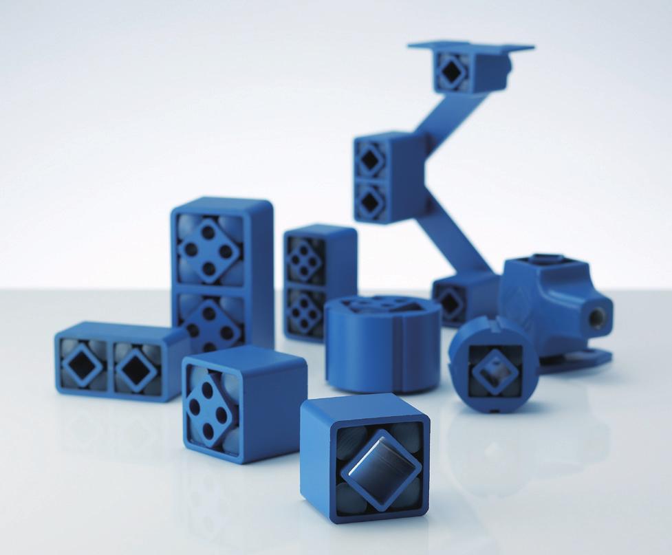
1 Rubber spring ROSTA Suspension-Tensioner

2 A Unique Structure And Operation Principles As A Multi-Functional Mechanical Elements Carry Out Stable Tensioning, Vibration Absorption And Noise Reduction. Rubber springs ROSTA are composed of metallic inner and outer shells and columnar rubber pieces. Columnar rubber pieces are press fit between the inner and outer shells which have 45 displacement. The spring characteristics are non-linear and columnar rubber pieces are compressed as they roll and are actuated. Thus, shaking motion is correctly transmitted and vibration and noise are absorbed at the same time. The tensioners are rich in elasticity. Permanent set is slight and the tensioners strongly resist impact loads and excel in durability. R U B B E R S P R I N G R O S TA


3 1. Large Torsional Angle A unique structure with rolling and compressing rubber, torsional angles can be allowed up to ± Ideal Spring Characteristics 3. Not only non-linear characteristics of spring, but also other directions as upper, lower, left and right sides can be applicable. Excellent Vibration and Shock-Absorbing Action A damping rubber has been adopted which is rich in elasticity, excellent in insulation of vibration. The intrinsic damping function of rubber is much larger compared with the metal, and comparatively obtains a significant damping effect. 4. Simple Structure, Excellent Durability Composition of 4 rubber pieces, metallic inner and outer shells -- light and compact. The preliminary compression rubber pieces are built in, elaborating an excellent durability for the fluctuations and the impact load. 5. Daily Maintenance Free The metals do not come in contact each other so that they will not wearout. Moreover, it will not get affection of water and dust so that daily maintenance is unnecessary. 6. Not Affected By Temperature Change Operation temperature range: -40 C to 80 C.


4 R U B B E R S P R I N G R O S TA Suspension-Tensioner Equipped With Spring, Damper And Bearing Function. Rubber spring ROSTA is a suspension unit. It is a unique, simple structure with columnar rubber pieces pressed to fit in between metallic inner and outer shells, and even from Machine Industry to transportation, removal equipment, recreation facilities, and the amusement equipment can be used as a multi-purpose mechanical elements. Moreover, metallic portions do not come in contact, it is excellent in durability because of a simple structure, and also daily maintenance is unnecessary. Suspension-tensioner equipped with spring, damper and bearing function Spring function Torsional angles can be allowed up to± 30. The spring characteristics are nonlinear and torsional rigidity increases as the load increases. The torque characteristics are decided by the length of the tension. Moreover, loads in all directions of tensile, compressive and shear loads, can be supported. Damper function Inner friction of rubber bodies is more than 1,000 times compared with a metal (spring steel). This allows early stopping of vibration caused by a low amplitude or shock during resonance. Tensioners are used as shock absorbers, vibration isolators, anti-vibration supports and other purposes. Bearing function Tension rubber suspensions can transmit high-period shaking motion while absorbing vibration. Normally, durability of bearings lowers if transmission of shaking motion or oiling or greasing is not adequate. The bearing function provided by the tensioners can replace b a ll a n d n e e d l e b e a r i n g s without requiring routine maintenance service. Bearing function Compression function Shock absorption function Tension function Hinge function Shaking function Spring function Multi-functions, multi-purposes - ROSTA Suspension Unit Shapes of inner and outer shells, materials, installation method and two single parts connected shapes - There are six kinds of basic units ready to serve. It is a multi-purpose mechanical element that can be used on wide-range freely.


5 F U LL LINEUP TENSIONER DEVICES The basic tensioner unit - SE model is integrating the inner shell and metal arm, and the outer shell and flange. The RSE model is a belt tensioner combining an aluminum alloy roller with the SE model. And the NSE model is a chain tensioner combining a sprocket idler with the SE model. ANTI-VIBRATION MOUNTINGS The dual-connected suspension unit, DO-A type, is combined to bracket to form the antivibration mounting ESL model and V model. ESL model is the best for anti-vibration at the medium and low frequency and V model is suitable for comparatively high frequency. All models are designed as applicable for various directions of installation, compression, tension and shearing and allows the load in any direction. OSCILLATING MOUNTINGS Shaking mount and drive head supporting a vibration conveyer or sieving machine can be designed by the ROSTA suspension unit. There are two main categories of oscillating mounting machines to excite oscillation, one is by crankmotion and the other is by vibrating motor. The former type, AU model, is a shaking mount used together with the drive-head RST model. And the latter type, AB model, is not only a mount, but can also be used as an anti-vibration mounting of the low frequency.


6 ROSTA Tensioner Maintains Appropriate Tension Of The Belt, And Automatically Absorbs Slack, Vibrations, And Shocks Of The Chain. The ROSTA tensioners can be used for tensioning, pressure rollers, and dumpers. The basic structure has an arm pre-installed to the inner shell of the ROSTA suspension unit. The outer shell has a flange shape. Installation can be done using only one center bolt, which allows easy installation for maintenance of appropriate belt tension, absorption of chain slack, the scraper of the conveyor belt, and pressure rollers. Moreover, the arm has two mounting holes (normal and hard) so that the idler mounting position can be selected according to the operating load range. The lineup consists of three models: the standard SE model with a bare arm, the RSE model with a pre-installed pulley idler, and the NSE model with a pre-installed sprocket idler. ROSTA Tensioner Tensioner unit + Pulley idler +Sprocket idler SE model RSE model NSE model Structure Outer shell Rubber Inner shell SE MODEL RSE MODEL NSE MODEL Pulley idler Sprocket idler Tensioner unit Tensioner unit Tensioner unit 4

7 ROSTA Tensioner ò Load range : 0N to 2600N ò Torsional angle : 0 to 30 ò Operating temperature range : 40 C to 80 C Tensioner 15
![ROSTA TENSIONER SE MODEL Specification Model Load range F [N] Maximum displacement S1 [mm] Maximum displacement S2 [mm] Mass [kg] SE-11 0~80 40 30 0.20 SE-15 0~135 50 40 0.40 SE-18 0~350 50 40 0.](/docs-images/86/94556134/images/8-0.jpg "60 SE-27 0~800 65 50 1.70 SE-38 0~1500 87.5 70 3.55 SE-45 0~600 112.5 90 6.40 * Load range is for the normal position specification. Hard position load range 1.25 Normal position load range.")
8 ROSTA TENSIONER SE MODEL Specification Model Load range F [N] Maximum displacement S1 [mm] Maximum displacement S2 [mm] Mass [kg] SE-11 0~ SE-15 0~ SE-18 0~ SE-27 0~ SE-38 0~ SE-45 0~ * Load range is for the normal position specification. Hard position load range 1.25 Normal position load range. Dimension (normal) (hard) S1 S2 C A D T normal T F hard F L H1 H2 B D G C E P R A M N Unit [mm] Model A B C D E G H1 H2 L N P R T M SE M6 20 SE1 SE M8 25 SE2 SE M10 30 SE3 SE M12 40 SE4 SE M16 40 SE5 SE M20 50 SE6 CAD file No. Ordering Information Size 16
![ROSTA TENSIONER RSE MODEL Specification Model Load range F [N] Maximum displacement S1 [mm] Maximum displacement S2 [mm] Applicable belt Max.](/docs-images/86/94556134/images/9-0.jpg "rotational speed [min -1 ] Mass [kg] RSE-11 0~80 40 30 A 8000 0.25 RSE-15 0~135 50 40 B 8000 0.60 RSE-18 0~350 50 40 B 8000 0.80 RSE-27 0~800 65 50 C 6000 2.15 RSE-38 0~1500 87.5 70 5000 4.")
9 ROSTA TENSIONER RSE MODEL Specification Model Load range F [N] Maximum displacement S1 [mm] Maximum displacement S2 [mm] Applicable belt Max. rotational speed [min -1 ] Mass [kg] RSE-11 0~ A RSE-15 0~ B RSE-18 0~ B RSE-27 0~ C RSE-38 0~ RSE-45 0~ * Load range is for the normal position specification. Hard position load range 1.25 Normal position load range. Dimension L3 L2 L1 S1 (normal) C A D M1 F H1 B F D D1 G A M Model A B D D1 G H1 L1 L2 L3 M M1 CAD file No. RSE M6 20 M8 45 RSE1 RSE M8 25 M10 60 RSE2 RSE M10 30 M10 60 RSE3 RSE M12 40 M12 75 RSE4 RSE M16 40 M RSE5 RSE M20 50 M RSE6 * For detailed dimensions of the tensioner part, refer to the dimension table of the SE model. * For details of the pulley idler, refer to Options on page 19. Unit [mm] Ordering Information Size The latest CAD data can be downloaded from our website. ht t p: //w w w. m ikipulley.co.jp/ C A D The CAD mark indicates that CAD data is available by CD-ROM. The CAD file No. represents the file name in the CD-ROM. 17
![ROSTA TENSIONER NSE MODEL Specification NSE-15 NSE-18 NSE-27 NSE-38 NSE-45 Model Load range F [N] Maximum displacement S1 [mm] Maximum displacement S2 [mm] Applicable chain Mass [kg] -35S 0.](/docs-images/86/94556134/images/10-0.jpg "55 0~135 50 40 35-35D 0.70-35S 0.75 35-35D 0.90 0~350 50 40-40S 0.83 40-40D 1.1-50S 2.1 50-50D 2.5 0~800 65 50-60S 2.2 60-60D 2.8-80S 4.5 0~1500 87.5 70 80-80D 5.4-100S 7.5 100-100D 9.4 0~2600 112.")
10 ROSTA TENSIONER NSE MODEL Specification NSE-15 NSE-18 NSE-27 NSE-38 NSE-45 Model Load range F [N] Maximum displacement S1 [mm] Maximum displacement S2 [mm] Applicable chain Mass [kg] -35S ~ D S D ~ S D S D 2.5 0~ S D S 4.5 0~ D S D 9.4 0~ S D 10.9 * Load range is for the normal position specification. Hard position load range 1.25 Normal position load range. Dimension M2 S1 (normal) C A D Y U F H1 B F D L3 G A M Unit [mm] NSE-15 NSE-18 NSE-27 NSE-38 NSE-45 Model A B D G H1 L3 U Y adjustment range -35S D S D S D S D S D S D S D S D * For detailed dimensions of the tensioner part, refer to the dimension table of the SE model. * The symbol "S" at the end of the size indicates a single row of sprocket, and "D" indicates two rows of sprockets. * For details of the sprocket idler, refer to Options on page 19. M M2 CAD file No. M8 25 M10 55 NSE1 M10 30 M10 55 NSE2 M12 40 M12 80 NSE3 M16 40 M NSE4 M20 50 M NSE5 Ordering Information Size Sprocket nominal designation 18

11 ROSTA TENSIONER Options Idler/Bracket Pulley Idler RA Model D A C B L1 d E d1 Model A B C D d d1 E L1 Bearing RA ZZ RA-15/ ZZ RA ZZ RA ZZ RA ZZ * Fixing bolts and nuts for the pulley idler are accessories. * Material: Aluminum alloy. Unit [mm] Sprocket Idler N Model O.D P.D d1 d T B Single row: S N-15-35D O.D O.D P.D P.D DH DH d1 d1 d d N-38-80D L T T N D,120D B B B B L Double row: D Model O.D P.D B DH d d1 L T Teeth Bearing N-15-35S D N-18-40S D N-27-50S D S D N-38-80S D S D N S D Unit [mm] ZZ ZZ ZZ ZZ ZZ ZZ ZZ * Fixing bolts and nuts for the sprocket idler are accessories. * The symbol "S" at the end of the size indicates a single row of sprocket, and "D" indicates two rows of sprockets. Bracket WS/WD Model U J C A D C A D S T K D G H2 H1 A B E F C Unit [mm] Model Applicable tensioner A B C D E F G H1 H2 J K S T U CAD file No. WS-11/ WD-15 SE,RSE,NSE WD1 WS-15/ WD-18 SE,RSE,NSE WD2 WS-18/ WD-27 SE,RSE,NSE WD3 WS-27/ WD-38 SE,RSE,NSE WD4 WS-38/ WD-45 SE,RSE,NSE WD5 WS-45/ WD-50 SE,RSE,NSE WD6 The latest CAD data can be downloaded from our website. ht t p: //w w w. m ikipulley.co.jp/ C A D The CAD mark indicates that CAD data is available by CD-ROM. The CAD file No. represents the file name in the CD-ROM. 19
12 ROSTA TENSIONER Design Check Items Selection ò RSE Model Find the belt size, belt appropriate tension (required tension), and belt deflection angle q. Using the easy selection graph below, select the size from the intersection of the belt size or appropriate tension and the belt deflection angle q. The appropriate tension varies depending on the number of belts. ROSTA mounting angle is set to 15. ò NSE Model For chain transmission, no excessive initial tension is required on the chain because of the engagement with the sprocket. Therefore, the chain tensioner only needs to apply small tension sufficient to eliminate slack. Select the tensioner size appropriate for the chain size from the table below. In this case, the set angle of the tensioner should be 10 to 15. For a longer chain, consider the weight of the chain itself. Belt appropriate tension (required tension) [N] RSE-45 RSE-38 RSE-27 RSE-18 RSE-15 RSE-11 Chain size 35S 35S 35D 35D 40S 40D 50S 50D 60S 60D 80S 80D 100S 100D 120S 120D NSE size NSE-15-35S NSE-18-35S NSE-15-35D NSE-18-35D NSE-18-40S NSE-18-40D NSE-27-50S NSE-27-50D NSE-27-60S NSE-27-60D NSE-38-80S NSE-38-80D NSE S NSE D NSE S NSE D Belt angle for mounting the tensioner [ ] Reference Ls Dp dp C Dp: Large pulley diameter dp: Small pulley diameter C: Distance between shafts Lb: Length of the belt used T0: Belt appropriate tension (Dp+dp) Belt length:le=2c (Dp+dp) 2 4C Span length:ls= C 2 (Dp dp)2 4 Belt deflection:l=lb Le Belt angle: =2sin -1 Ls (Ls+L) Tensioner setting load:f=t0 cos( ) 2 20
13 Displacement S [mm] Load F [N] Spring Characteristics ò Torsional Angle - Load Curve 2000 SE F SE-38 SE SE SE SE Angle [ ] ò Torsional Angle - Displacement Conversion S SE-45 SE SE SE-15/18 SE Angle [ ] * Spring characteristics are normal position specifications. The latest CAD data can be downloaded from our website. ht t p: //w w w. m ikipulley.co.jp/ C A D The CAD mark indicates that CAD data is available by CD-ROM. The CAD file No. represents the file name in the CD-ROM. 21
14 ROSTA TENSIONER Design Check Items Idler Setting Installation Always set the idler on the deflection side of the chain/belt. For forward reverse rotation, set the idlers on both sides. Adjust the positioning notch on the flange part of the ROSTA tensioner to the designed position. Installation is made easily by placing a mark corresponding to the notch on the supporting plate on which the ROSTA tensioner is to be installed. This notch can also be used as a detent. To apply tension from the outside of the chain/belt, set the idler on the side of the smaller sprocket (pulley). On the other hand, to apply tension from the inside, set the idler on the side of the larger sprocket (pulley). Flange part Install the ROSTA tensioner on the machine using the attached hexagonal bolt (A). Check the strength of the machine installation part and flatness of the installation surface. If the ROSTA tensioner cannot be installed directly on the machine, use the bracket (WS/WD model). Set the chain tensioner so that three or more teeth of the sprocket idler are engaged with the chain. Excessive tension on the chain/belt dramatically shortens the life of the chain/belt as well as the life of the bearing. Allow appropriate looseness. As a guide, the setting angle is about 10 to 15. To apply tension from the inside of the V belt, use a V pulley idler. For a timing belt, use a timing idler. The tensioner mounting bolt has a strength category of 8.8. Tighten it with the following tightening torque. Bolt size Appropriate tightening torque [N m] M6 10 M8 25 M10 50 M12 90 M M Bracket Hexagonal boltl (A) Hold the outer shell of the ROSTA tensioner with a spanner, and tighten the attached hexagonal bolt (A) to secure the ROSTA tensioner. When the ROSTA tensioner is used with an angle close to its allowable angle, use a torque wrench to tighten it at the specified torque. Hexagonal bolt (A) Install the sprocket idler to the ROSTA tensioner. First, secure the supporting bolt (D) firmly to the arm with the retaining nut (B). After that, adjust the sprocket idler within the specified installation range (catalog Y dimensions) to align it with the travel path of the chain, and secure it with two nuts (C). Retaining nut (B) Supporting bolt (D) Arm Nut (C) Always set the idler on the inside of the arm. If it is necessary to set it on the outside of the arm, set it as close to the arm as possible. In this case, the allowable torsional angle is ±15 or less for the maximum. (Outside) (Inside) * Avoid oil or grease on the rubber (NR) because it has insufficient oil/grease resistance. 22

15 Tensioner 23
16 APPLICATION Motor Support Base Conveyor Centering Equipment Belt Cleaner Support Roller Suspension Cleaner Brush Suspension Carrier Roller Anti-Vibration 40
17 Segregator Support Vibration Motor Support Base See-Saw Support Crane Vibration Isolation and Sound Proofing Suspension Vibration Isolation & Sound Proofing 41
18 Safety Precautions (Please read prior to use) Please read carefully through the instruction manual and the technical information for proper use and safety. In this manual, safety precautions are classified into "DANGER" and "CAUTION". 2.Mounting precautions ò Tighten bolts or screws completely. When death or serious injury may result by mishandling Depending on the tightening adjustment of bolt or screw, exceptionally dangerous situations such as product damage or performance degradation could occur. Always use a calibrated torque wrench and clamp at the tightening torque specified by Miki Pulley. Tighten the bolts with the torque specified by the bolt manufacturer unless otherwise specified. When disability or only physical damage may result by mishandling Equipment use (atomic energy, aerospace, medical treatment, transportation, or various safety devices) that may result in serious bodily injury or loss of life directly by mechanical failure or mishandling, careful examination is necessary. Contact us for further information. The company has taken all possible measures to produce a quality product; however, please pay attention to safety measures for the machine in case anything goes wrong. ò Do not turn on the power of the equipment. It is very dangerous if the driving part starts by accident while mounting the product. Be sure that the main power of the equipment is turned off. 1.Structural precautions ò Use a safety cover. Touching the product during operation could cause injury. Place a safety cover to avoid any accident. Additionally, set up a safety mechanism for quick stop of the product when opening the cover. ò Use the product within the specified maximum tolerance. The installation of the product must be performed within the specified maximum tolerance. Using the product with more than the maximum tolerance could cause damage or adverse effect on the equipment. ò D o n o t u s e t h e p r o d u c t i n a flammable or explosive atmosphere. The parts are supported by rubber. In some applications, they may become charged and produce sparks during discharge. Do not use the product near flammable liquids or in the presence of gas and other explosive air particles. ò Wear protective equipment. To avoid any injury during installation of the product, make sure to wear protective equipment such as safety glasses or gloves. ò Set up a safety mechanism. The driven and driving sides could be completely detached in case the product is damaged. Set up a safety mechanism such as a safety brake to avoid any danger. ò Carry and mount the product by using a hoist. Lifting of a heavy weight could cause back injury. Use a hoist when carrying or mounting the product. 42
19 3.Cautions during operation ò Do not touch the product during operation. Touching the product during operation may cause injury. Make sure not to touch the product during operation. 4.Cautions for maintenance and inspection ò Do not turn on the power of the equipment. It is extremely dangerous if the driving part starts operating by accident while dismounting the product. Make sure that the main power of the equipment is off. ò When abnormal noises or vibrations occur, stop operation immediately. If abnormal noises or vibrations occur during o p e r a tion, i m p r o p e r m o u nting s h o u l d b e considered. Do not leave the situation as it is. It may cause damage to the equipment itself. Also, for reasons other than above, the belts and other screws may loosen or become defective even if the product is mounted correctly. ò Do not dismantle the product. We will refuse to take responsibility as to the damaged product that is dismantled, remodeled or repaired by a third party except our company and the designated company. Therefore, for the product that the assembly process or procedure of dismantlement is described in the manual, we will not be responsible as well. Please use our service network for repair and dismantlement. ò Do not use the product in an environment that could cause harmful effects. Do not use the product in an environment where chemicals may spill, humidity is high, or temperature is too high or too low. 5.Cautions for disposal ò Do not leave the product around where young children may play. ò Ask a waste-control-collection company for disposal. ò O p e r a t e t h e p r o d u c t w i t h i n t h e "maximum permissible torsional angle." Using the product outside the "ma ximum permissible torsional angle" may damage the product or have harmful effects on the equipment. Always operate the product within the specified "maximum permissible torsional angle." Please note that this safety precautions and specification described in each manual may be changed without prior notice. Contact Miki Pulley for additional information or questions on these precautions. ò Operate the product within the "permissible loading force." Using the product outside the "permissible loading force" may damage the product or have harmful effects on the equipment. Always operate the product within the specified "permissible loading force." ò Operate the product within the specified maximum permissible misalignment. Using the product outside the "ma ximum permissible misalignment" may damage the product or have harmful effects on the equipment. Always operate the product within the specified "maximum permissible misalignment." 43

 Japanese, English,")


20 Please Consult Our Website. More information on new products and on events such as tradeshows 01 Multilingual website (4 languages) Japanese, English, Chinese (simplified characters) and Korean. *Some product information is available in Japanese only. 01 Top page 02 Downloading Latest information including a catalog, instruction manual and CAD data can be downloaded. 05 Instruction manual PDF page 04 Catalog PDF page 03 Product information page 02 Page for introduction of products 03 Enriched content Abundant information other than product information is also provided. 08 International network information page 07 Tradeshow information page 06 A d v e r t i s e m e n t a n d s e l f - introduction page 44


21 All Kinds of Mikipulley's Products. Motion control and power transmission equipment Flexible Couplings Speed changers and Reducers Suspension/Rotation Speed Indicators Inverters/ DD Motors Electoromagnetic Clutches and Brakes ETP Bushings 45
22 461 Imai-Minami-cho, Nakahara-Ku, Kawasaki-Shi, Kanagawa-Ken, , Japan ' SO-RST(en)-001A
Product Range Modules ROSTA Tensioner Devices
 Product Range Modules ROSTA Page 17 14 Tensioning Technology Chain Tensioning Roller chains are power transmission components with positive transmission which, by virtue of their design are subject, depending
ROSTA Tensioner Devices
 33 Tensioning Technology Chain Tensioning Roller chains are power transmission components with positive transmission which, by virtue of their design are subject, depending on quality, to elongation as
Flexible Couplings and Hub-shaft Connections COUPLINGS
 Flexible Couplings and Hub-shaft Connections COUPLINGS High-reliability Metal Plate Spring Format Realizing Its Best Shape Through Finite Element Analysis is an ultrahigh-rigidity flexible coupling derived
ROSTA Tensioning Motorbases Type MB. self-adjusting maintenance-free overload-proof non-slip dampen harmful vibrations extend belt drive
 83 Technology ROSTA Tensioning Motorbase Type MB for Belt Drives The ROSTA elastic tensioning motorbase type MB, with the rubber suspension unit as swivel mounting, compensates continuously for all stretching,
ROSTA Tensioning Motorbases Type MB. self-adjusting maintenance-free overload-proof non-slip dampen harmful vibrations extend belt drive
 Technology ROSTA Tensioning Type MB for Belt Drives The ROSTA elastic tensioning motorbase type MB, with the rubber suspension unit as swivel mounting, compensates continuously for all stretching, hopping,
Instruction Manual. Table of Contents. Powder Clutch, Brake MODEL ZKB-AN,BN Powder Clutch ZKB-YN,XN Powder Brake
 ZJ-267A Powder Clutch, Brake MODEL ZKB-AN,BN Powder Clutch ZKB-YN,XN Powder Brake Instruction Manual Table of Contents Cautions on Safety - - - - - - - - - - - - - - - - - 1 1. Cautions before use - -
Flexible Couplings and Hub-shaft Connections COUPLINGS
 Flexible ouplings and Hub-shaft onnections OUPLING Jaw ouplings With A implified tructure Tucking A Buffer Material Between Two Hubs Features of Buffer Material TAR FLEX, the flexible couplings, are derived
Townsend Bearings. Rosta Tensioner Devices. Revision 1
 Townsend Bearings Rosta Revision 1 Tensioning Technology Chain Tensioning Roller chains are power transmission components with positive transmission which, by virtue of their design are subject, depending
PARAFLEX Pin bushing Couplings That Keep Shaft Reaction Force from Mounting Misalignment Extremely Low
 Pin Bushing Pin Bushing stiffness flexibility damping Easy to mount and remove RoHS nominal tque 25 Be ranges φ3 ~ 22 Operating temperature [ ] -30 ~ 100 Backlash Extremely small size Driver Servo mot,
COUPLINGS Flexible Couplings and Hub-shaft Connections
 COUPLINGS Flexible Couplings and Hub-shaft Connections Flexible Couplings and Hub-shaft Connections COUPLINGS Atención al Cliente 902 208 608 461 Imai-Minami-cho, Nakahara-Ku, Kawasaki-City, Kanagawa,
ROSTA MOTORBASES ROSTA. Self-Tensioning Motor Mount for Belt Drives. without slippage self-adjusting maintenance-free
 MOTORBASES Self-Tensioning Motor Mount for Belt Drives without slippage self-adjusting maintenance-free Technology Tensioning Motorbase Type MB for Belt Drives The elastic tensioning motorbase type MB,
High performance metal disk coupling SERVOFLEX SFF (N)
") High performance metal disk coupling SERVOFLEX SFF (N) Best design for the latest servo motor SERVOFLEX for feed shaft which introduce the high precision clamp method Coupling outer diameter, lineup for
High performance metal disk coupling SERVOFLEX SFF (N) Best design for the latest servo motor SERVOFLEX for feed shaft which introduce the high precision clamp method Coupling outer diameter, lineup for
ELECTROMAGNETIC CLUTCH AND BRAKE UNITS
 -ACTUATED CLUTCHES AND BRAKES CLUTCH AND BRAKE UNITS Application Printing machinery, bookbinding machinery, woodworking machinery, semiconductor manufacturing equipment Connection and Release, Required
Instruction and Installation Manual
 Instruction and Installation Manual ROSTA Tensioner Devices Tensioners Accessories -G -W -R Sprocket wheel N Chain rider P Oil resistant Up to + 120 C Reinforced Sprocket wheel set Chain rider set -I -F
Design Check Items. Mounting SFF SFM MODEL
 SFF SFM MODEL Design Check Items Mounting SFF/SFM models are finished-assembly products. The concentricity of the right and left inner diameters of the coupling is set by assembling the parts with high
ROSTA RUBBER SUSPENSION UNITS. Multifunctional Modules for the Machine Industries. guiding tensioning absorbing ROSTA
 RUBBER SUSPENSION UNITS Multifunctional Modules for the Machine Industries guiding tensioning absorbing Product Range Modules Rubber Suspension Unit Type DR-S Page 19 Housing made out of steel, inner square
INSTRUCTION MANUAL A PEX N1 DAMPER. Height Adjustable Coil Over Damper Kit PRODUCT CODE 269AM020. Vehicle Application
 INSTRUCTION MANUAL A PEX N1 DAMPER Height Adjustable Coil Over Damper Kit PRODUCT CODE 269AM020 (Table1) Vehicle Application Application Vehicle Vehicle Model Engine Model Year MITSUBISHI CT9A 4G63 03-
ROSTA Tensioner Devices
 ROSTA Maintenance-free tensioner systems for belt and chain drives Easy to install available in 7 standard sizes wide range of accessories available Customer Benefits from using ROSTA SE Guarantees the
3 Axles and brakes. 3.1 Function and construction of the axles Construction Function
 3 Axles and brakes 3.1 Function and construction of the axles 3.1.1 Function Each wheel has an independent suspension system in the axle body (1), so that individual wheel suspension is provided. The swinging
Engineering Data Tensioner Arms idler Sprocket Sets Idler Roller Pulley Sets
 CHAIN & PULLEY TENSIONERS Engineering Data Tensioner Arms idler Sprocket Sets Idler Roller Pulley Sets ENGINEERING DATA TENSIONING TECHNOLOGY Chain & V-Belt Tensioning Roller chains are power transmission
ACTUATORS GENERAL CATALOG
 CAD drawing data catalog is available. ACTUATORS GENERAL CATALOG ROTARY ACTUATORS VANE TYPE SERIES CONTENTS RAN (Standard Type) Basic Model and Configuration 259 Specifications 26 Order Codes 264 Dimensions
A B 0 0 C D E 6 7 G F F H 8 9 K M O O L N I J 1
 1 2 1 5 4 3 2 2 1 6 3 8 7 1 9 4 C A B 5 0 0 D E 6 G 7 F F H 8 K 9 M O O I J L N 1 GENERAL OPERATIONAL PRECAUTIONS 1. Keep work area clean. Cluttered areas and benches invite accidents. 2. Avoid dangerous
PROPULSION EQUIPMENT DOCUMENTATION SHEET. Propulsion Equipment
 PROPULSION EQUIPMENT General Vessels like rescue boats, patrol boats and anchor handling boats have to show 100 percent performance, even in the most extreme conditions. These so called s pecial seagoing
POSI-LOCK. Connects the Shaft and Hub with the Wedging Action of the Tapered Surface. Mechanical Shaft Lock ETP BUSHINGS
 Mechanical Shaft ock POSI-OCK Mechanical Shaft ock POSI-OCK Application Machine tool, pump, molding machine, printing machine, palletizing robot, various jigs and tools Connects the Shaft and Hub with
Installation and Operational Instructions for EAS - HTL housed overload clutch Sizes 01 3 Type 490._24.0
 Please read these Operational Instructions carefully and follow them accordingly! Ignoring these Instructions may lead to malfunctions or to clutch failure, resulting in damage to other parts. Contents:
Installation and Operational Instructions for EAS -Compact overload clutch, Type 49_. 4._ Sizes 4 and 5
 Please read these Operational Instructions carefully and follow them accordingly! Ignoring these Instructions may lead to malfunctions or to clutch failure, resulting in damage to other parts. Contents:
High precision dual rubber coupling STEPFLEX STF
 High precision dual rubber coupling STEPFLEX STF STEPFLEX High-damping couplings Our newly developed laminated rubber element achieves high damping and low reaction force. Their unitized construction with
INSTRUCTION MANUAL. A PEX S1 DAMPER Height Adjustable Coilover Damper Kit PRODUCT CODE - 268AM020
 INSTRUCTION MANUAL A PEX S1 DAMPER Height Adjustable Coilover Damper Kit PRODUCT CODE - 268AM020 (Table 1) Vehicle Application Application Vehicle Vehicle Model Engine Model Year MITSUBISHI LANCER EVOLUTION
accidents which arise due to nonobservance and the safety information herein.
 2000LB WINCH Model: 7247 CALIFORNIA PROPOSITION 65 WARNING: You can create dust when you cut, sand, drill or grind materials such as wood, paint, metal, concrete, cement, or other masonry. This dust often
ROSTA Tensioner Devices
 OSTA Maintenance-free tensioner systems for belt and chain drives Easy to install available in 7 standard sizes wide range of accessories available Customer Benefits from using OSTA SE Guarantees the lowest
Maintenance & Inspection Manual
 Maintenance & Inspection Manual Chip Conveyor This manual includes the description for both floor type and scraper type For Safety Make sure that an experienced operator operates this machine. DO NOT operate
SERVO MOTORS BRUSHLESS SERVO MOTORS OPERATING INSTRUCTIONS 2016
 SERVO MOTORS BRUSHLESS SERVO MOTORS OPERATING INSTRUCTIONS 2016 3009/16 en Ed.02.2016 Read these Operating Instructions before performing any transportation, installation, commissioning, maintenance or
U.S. TSUBAKI DRIVE CHAINS
 DRIVE CHAINS Contents Page ANSI RS ROLLER CHAIN A- ~ A-4 INTRODUCTION A- ~ A-5 RS5 THROUGH RS4 A-6 ~ A-9 HEAVY SERIES A- RS DOUBLE PITCH ROLLER CHAINS A- SELECTION AND ENGINEERING INFORMATION A- ~ A-4
 CONTENTS 0.005 0.004 0.003 0.002 0.001 0 SE15 SE23SC23 SE30SC30 SE45SC45 0 200 400 600 800 1000 Category Option Manufactured by order (Note 8) Item SG series SE series SC series Motor Intermediate
Installation and Operating Instructions for EAS -NC clutch Type 45_. _. _ Sizes 02 and 03
 Table of contents: Please read and observe this Operating Instruction carefully! A possible malfunction or failure of the clutch and any damage may be caused by not observing it. Page 1: - Table of contents
Oscillating Mountings
 Type HS for hanging screens H B F E HS 7 38 D A HS 45 50 HS 50- Z C G M L M L M L Art. o. Type Load capacity Gmin. G [] A unloaded A* load B unloaded B* load C D E F H L M Weight [kg] 07 311 001 HS 7 500
Installation, Maintenance & Parts Manual
 Installation, Maintenance & Parts Manual 7200/7300 Series Top Mount Drive Package for Heavy Load 90 Sanitary Gearmotors Table of Contents Warnings General Safety.................... 2 Introduction................................
Sisu S-Cam Drum Brakes
 Sisu S-Cam Drum Brakes (For hub reduction rear axles since 1992) Maintenance Manual Sisu Axles, Inc. Autotehtaantie 1 P.O. Box 189 FIN-13101 Hämeenlinna Finland Phone int + 358 204 55 2999 Fax int + 358
FX-1100 Series MASS BURETTE FLOW DETECTOR INSTRUCTION MANUAL ONO SOKKI CO., LTD.
 FX-1100 Series MASS BURETTE FLOW DETECTOR INSTRUCTION MANUAL ONO SOKKI CO., LTD. 1. This document may not be reproduced, in whole or part, in any form or by any means without the prior written permission
Maintenance & Inspection Manual
 Maintenance & Inspection Manual Chip Conveyor This manual includes the description for both floor type and scraper type For Safety Make sure that an experienced operator operates this machine. DO NOT operate
Stopping Accuracy of Brushless
 Stopping Accuracy of Brushless Features of the High Rigidity Type DGII Series Hollow Rotary Actuator The DGII Series hollow rotary actuator was developed for positioning applications such as rotating a
TRANSMISSIONS. Mechanical Power Transmission
 TRANSMISSIONS Mechanical Power Transmission Dunlop BTL Ltd European Distribution Centre MPT House Brunswick Road Cobbs Wood Industrial Estate Ashford, Kent. UK TN23 1EL Contact us +44 (0)1233 663340 +44
Operation Manual for Torque Sensors with Slip Ring Transmission
 Operation Manual for Torque Sensors with Slip Ring Transmission For below and similar Types DR-1 DR-2 DR-12 DR-20 DR-2291 DR-2335 Internet: www.lorenz-sensors.com Page 1 of 15 Imprint Manufacturer, Place
Marine Engineering Exam Resource Review of Couplings
 1. What are rigid couplings used for? Used to join drive shafts together. True alignment and rigidity are required. Example Drive shafts and production lines, bridge cranes, solid shaft that needs to be
Exhaust Throttle (Needle) Valve ET
 Valve ET") http://www.pisco.co.jp CONTROLLER VALVE TUBE MAKE-TO-ORDER PRODUCTS Exhaust Throttle (Needle) Valve Exhaust Throttle (Needle) Valve ET 494 Exhaust Throttle (Needle) Valve with Silencer. Directly Connectable
http://www.pisco.co.jp CONTROLLER VALVE TUBE MAKE-TO-ORDER PRODUCTS Exhaust Throttle (Needle) Valve Exhaust Throttle (Needle) Valve ET 494 Exhaust Throttle (Needle) Valve with Silencer. Directly Connectable
Features of the LM Guide
 Features of the Functions Required for Linear Guide Surface Large permissible load Highly rigid in all directions High positioning repeatability Running accuracy can be obtained easily High accuracy can
Multi-Circuit Rotary Block
 http://www.pisco.co.jp FITTING CONTROLLER VALVE TUBE MAKE-TO-ORDER PRODUCTS Multi-Circuit Block for Rotating Applications Multi-Circuit Rotary Block 302 Make to Order Suitable for Low-Speed Rotating Applications
TECHNICAL GUIDE FOR PROXIMITY SENSORS DEFINITIONS YAMATAKE PROXIMITY SENSOR CATEGORIES
 TECHNICAL GUIDE FOR PROXIMITY SENSORS DEFINITIONS "" includes all sensors that detect the presence of a metallic object approaching the sensing face or near the sensing face without mechanical contact.
Cat. No. I526-E1-1 USER S MANUAL 3G3IV-PLKEB2 /4. Braking Resistor Units 3G3IV-PCDBR2 B/4 B. Braking Units
 Cat. No. I526-E1-1 USER S MANUAL 3G3IV-PLKEB2 /4 Braking Resistor Units 3G3IV-PCDBR2 B/4 B Braking Units Thank you for choosing an OMRON Braking Resistor Unit and Braking Unit. Proper use and handling
DIGITAL TORQUE GAUGE MODEL BTGE-G
 DIGITAL TORQUE GAUGE MODEL BTGE-G OPERATING INSTRUCTION BTGE-G BTGE-G Model To use this product properly and safely, please read this manual carefully before use. If you have any question about the product
Package Contents Part A (3) I-Beam (1) Base (2) Other parts
 I-Beam (1) Base (2) Other parts") Page 1 Installation Instructions for 81245 Adjustable Height Gantry Crane 1-Ton Capacity Table of Contents Important Safety Information pg. 2 Specific Operation Warnings pg. 2 Main Parts of Product pg.
Page 1 Installation Instructions for 81245 Adjustable Height Gantry Crane 1-Ton Capacity Table of Contents Important Safety Information pg. 2 Specific Operation Warnings pg. 2 Main Parts of Product pg.
1. General Description
 General Description 1. General Description A: SPECIFICATION Front Rear Model Wheel arch height (Tolerance: +12 mm 24 mm ( +0.47 in 0.94 in)) mm (in) 376 (14.8) Camber (Tolerance: 0 45 Differences between
1. Remove the crankshaft pulley, engine coolant pump pulley and drive belt. 2. Remove the timing belt cover.
 DISASSEMBLY 1. Remove the crankshaft pulley, engine coolant pump pulley and drive belt. 2. Remove the timing belt cover. 3. Turn the crankshaft clockwise and align the timing marks so as to bring the No.
For advanced drive technology CLAMPEX. Shaft-Hub-Connection. KTR Precision Joints CLAMPEX
 technology CLAMPEX Shaft-Hub-Connection CLAMPEX KTR Precision Joints 07 technology Table of contents Page Brief information 09 Selection and calculation -5 CLAMPEX -Selection Shaft diameter = d 0 10 0
CONTENTS: 5740AH - 40 Ton Air/Hydraulic Shop Press 5750AH - 50 Ton Air/Hydraulic Shop Press OWNER'S MANUAL
 OWNER'S MANUAL CONTENTS: Page 1 Specifications 2 Safety Information and Warranty Information 3 Parts List 4-6 Assembly Instructions 7 Pump and Ram Assembly Instructions 8 Procedure for Bleeding Air 9 Pump
Speed Controller High Flow
 http://www.pisco.co.jp CONTROLLER VALVE TUBE MAKE-TO-ORDER PRODUCTS Speed Control Valve for High Speed Cylinder High Flow Speed Control Valve for Actuator. High Flow Type with Same Size as. Suitable for
OVERLOAD CLUTCHES FOR INDEX DRIVES
 The Driving Force in Automation OVERLOAD CLUTCHES FOR INDEX DRIVES WARNING WARNING This is a controlled document. It is your responsibility to deliver this information to the end user of the CAMCO indexer.
Butterfly Valves ASAHI AV VALVES
 Serial No. H-V030-E-8 Butterfly Valves Type 56: 400mm (16 ) Body: PP, PVDF Type 75: 450-600mm (18-24 ) Body: PP, PVDF Type 56D: 400mm (16 ) Body: PDCPD Type 75D: 450-600 mm (18-24 ) Body: PDCPD Contents
WARNING. Electric Recovery Winch. General Safety Precautions
 1 Electric Recovery Winch Thanks for purchasing a WINCH. This manual covers operation and maintenance of the winch. All information in this publication is based on the latest production information available
Disassembly / Reassembly Procedure
 08-T059 Disassembly / Reassembly Procedure HEAVY DUTY TYPE PNEUMATIC CYLINDER 10A-3 SERIES Failure to observe the instructions given in this manual could cause this equipment
Cross Tensioners. Frames. Bearings. Springs. Mounting Holes. Adjustment Marks
 Cross Tensioners Cross Tensioners provide constant belt or chain tension. Their automatic tensioning action translates into improved performance and extended life for most types of fixed-centre drives.
Lumitester PD-20 Control Kit
 日本語による取扱説明は 17 ページからとなります Lumitester PD-20 Control Kit Operation manual Thank you for purchasing the Lumitester PD-20 Control Kit. To use this kit safely and correctly, read this operation manual carefully
T8 Torque Sensor Operation Manual
 T8 Torque Sensor Operation Manual Page 1 of 11 Imprint Valid for... Reprint Interdiction Modification Torque sensor type T8 Reprints, even in extracts, only with written authority. Technical changes reserved.
114 NOSE SEIKO CO.,LTD NOSE SEIKO CO.,LTD
 114 NOSE SEIKO CO.,LTD NOSE SEIKO CO.,LTD 115 and Part Code Applicable axis diameter Feature Part Code 5 ~ 3 General purpose cam follower with screwdriver groove on the stud head. Available with stainless
Roller Follower General Catalog
 General Catalog A Product Descriptions Features and Types... A20-2 Features of the... A20-2 Structure and Features... A20-2 Types of the... A20-3 Types and Features... A20-4 Point of Selection... A20-6
ROSTA Tensioner Devices
 OSTA Maintenance-free tensioner systems for belt and chain drives Easy to install available in 7 standard sizes wide range of accessories available OSTA Customer Benefits from using OSTA SE Guarantees
Mini Lever Hoist. Owner s Manual
 Mini Lever Hoist Owner s Manual WARNING: Read carefully and understand all ASSEMBLY AND OPERATION INSTRUCTIONS before operating. Failure to follow the safety rules and other basic safety precautions may
CLAMPEX KTR 603 Operating/Assembly instructions
 1 of 9 The CLAMPEX clamping set is a frictionally engaged, detachable shaft-hub-connection for cylindrical shafts and bores without feather key. Table of contents 1 Technical data 2 2 Advice 6 2.1 General
146cc SCUT Cylinder Kit Instruction Manual
 146cc SCUT Cylinder Kit Instruction Manual JP PAT. US PAT. The ceramic-coated cylinder is used. Item No. (Cylinder Kit) (Piston Kit) Fitting Ape100, XR100 Motard, CRF100F, XR100R But limited tobikes fitted
SLIDE TABLES CONTENTS
 CAD drawing data catalog is available. ACTUATORS GENERAL CATALOG SLIDE TALES CONTENTS Features 979 Safety Precautions, Handling Instructions and Precautions 981 Specifications 985 Order Codes 986 Inner
ROSTA-Tensioner Devices
 -Tensioner Devices Maintenance-free tensioner systems for belt and chain drives Easy to install available in 7 standard sizes wide range of accessories available Customer Benefits from using OST SE Guarantees
Before equipment use, please read this operation manual carefully. Serial Number: Date Purchased:
 Pushed & Geared Trolleys OPERATION MANUAL This operation manual is intended as an instruction manual for trained personnel who are in charge of installation, maintenance, repair etc. Before equipment use,
GATE VALVES. Type P (Standard: Plug) Type S (Soft Seal) Contents. (1) Be sure to read the following warranty clauses of our product 1
 Type S (Soft Seal) Contents. (1) Be sure to read the following warranty clauses of our product 1") Serial No. H-V011-E-12 GATE VALVES Type P (Standard: Plug) Type S (Soft Seal) Contents (1) Be sure to read the following warranty clauses of our product 1 User s Manual (2) General operating instructions
Serial No. H-V011-E-12 GATE VALVES Type P (Standard: Plug) Type S (Soft Seal) Contents (1) Be sure to read the following warranty clauses of our product 1 User s Manual (2) General operating instructions
3. BEARING ARRANGEMENT DESIGN
 3. BEARING ARRANGEMENT DESIGN 3.1 GENERAL PRINCIPLES OF ROLLING BEARING ARRANGEMENT DESIGN Rotating shaft or another component arranged in rolling bearings is guided by them in radial as well as in axial
Volute Casing Centrifugal Pumps in In-line Design with Magnetic Drive. Series CNI-M
 Volute Casing Centrifugal Pumps in In-line Design with Magnetic Drive Series CNI-M Usage For pumping toxic, volatile, explosive or other fluids harmful to the environment which call for service of hermetically
Timing Belt: Service and Repair
 2000 Hyundai Sonata L4-2.4L Page 1 Timing Belt: Service and Repair REMOVAL 1. Remove the crankshaft pulley, engine coolant pump pulley and drive belt. 2. Remove the timing belt cover. 2000 Hyundai Sonata
Differential Pressure Transmitter
 Specifications/Instructions Differential Pressure Transmitter General Model PY9000D is a differential pressure transmitter that uses a ceramic cantilever sensor. Deflection of the ceramic cantilever caused
Disassembly and Assembly
 K EN R 623 2-00 August 2006 Disassembly and Assembly 2506-15 Industrial Engine M G A (Engine) MGB (Engine) M G D (Engine) Important Safety Information Most accidents that involve product operation, maintenance
R310EN 2211 ( ) The Drive & Control Company
 The Drive & Control Company") eline Ball Rail Systems R310EN 2211 (2006.04) The Drive & Control Company Bosch Rexroth AG Linear Motion and Assembly Technologies Ball Rail Systems Roller Rail Systems Linear Bushings and Shafts Ball
eline Ball Rail Systems R310EN 2211 (2006.04) The Drive & Control Company Bosch Rexroth AG Linear Motion and Assembly Technologies Ball Rail Systems Roller Rail Systems Linear Bushings and Shafts Ball
Heavy-Duty Shock Absorbers HLS-110. Deceleration Technology. ONLINE Calculation and 2D / 3D CAD Download. F m
 Heavy-Duty Shock Absorbers HLS-110 Deceleration Technology ONLINE Calculation and 2D / 3D CAD Download F m V S Operating Principle Steel Cap Filling Valve Nitrogen Piston rod Operating Principle HLS models
for flex design of MOTION GUIDE Journal Bearing
 MOTION GUIDE for flex design of Motion Guide Systems provide the maintenance-free and smooth running of V-shaped rolling bearings fitted on both sides of flat rail. Various combinations of components are
Timing Belt Installation
 Timing Belt Installation The following is an installation guideline designed to combat problems resulting from improper installation of timing belt drives. 1) Loosen Motor. Check to make sure that the
2100, 2200, 2300 & 6200 Series Center Mount Drive Package for 90 Standard & Heavy Load Gearmotors
 00, 00, 300 & 600 Series Center Mount Drive Package for 90 Standard & Heavy Load Gearmotors Installation, Maintenance & Parts Manual Featuring: Technology DORNER MFG. CORP. INSIDE THE USA OUTSIDE THE USA
TOSHIBA Thermal Printer B-SX6T/SX8T SERIES. Maintenance Manual. Document No. EO Original Mar., 2006 (Revised ) PRINTED IN JAPAN
 PRINTED IN JAPAN") TOSHIBA Thermal Printer B-SX6T/SX8T SERIES Maintenance Manual Original Mar., 2006 (Revised ) Document No. PRINTED IN JAPAN TABLE OF CONTENTS Page 1. UNPACKING--------------------------------------------------------------------------------------------------------
TOSHIBA Thermal Printer B-SX6T/SX8T SERIES Maintenance Manual Original Mar., 2006 (Revised ) Document No. PRINTED IN JAPAN TABLE OF CONTENTS Page 1. UNPACKING--------------------------------------------------------------------------------------------------------
Diaphragm Valves Type 15
 Serial No. H-V031-E-8 Diaphragm Valves Type 15 User s Manual Contents (1) Be sure to read the following warranty clauses of our product 1 (2) General operating instructions 2 (3) General instructions for
Bowl feeder WV401-1 / Translation of operating and installation instructions
 Bowl feeder WV401-1 / 402-1 Translation of operating and installation instructions Copyright by Afag GmbH This operation instruction applies to: Bowl feeder WV401-1 Bowl feeder WV402-1 Type 230 V / 50
Instruction Manual for 136cc SCUT Cylinder Kit
 Instruction Manual for 136cc SCUT Cylinder Kit Item No. Fitting Ape100, XR100 Motard, CRF100F, XR100R But limited tobikes fitted with TAKEGAWA s Super Head Thank you for purchasing one of our TAKEGAWA's
Push-In Fitting Type Quick Exhaust Valve
 http://www.pisco.co.jp CONTROLLER VALVE TUBE MAKE-TO-ORDER PRODUCTS Push-In Fitting Type Valve Valve 482 Suitable for High-Speed Cylinder. Standard Valve is equipped with Silencer. Re-adjustment of exhaust
Support Units. FA Units
 Support Units FA Units Sungil Support Units EK, EF Type Support Units BK, BF Type Support Units AK, AF Type Support Units FK, FF Type Support Units Support Units Sungil Support Units Lock Nut Joint Unit
PRO INDOOR CYCLING BIKE
 PRO INDOOR CYCLING BIKE SF-B901 USER MANUAL IMPORTANT! Please retain owner s manual for maintenance and adjustment instructions. Your satisfaction is very important to us, PLEASE DO NOT RETURN UNTIL YOU
Index. 1. Important safety instructions Overview of the lift Installation instructions Operation instructions 8-9
 2 Index 1. Important safety instructions 4-5 1.1 Safety Warnings 1.2 Qualified personnel 1.3 Safety 1.4 Warning signs 2. Overview of the lift 6 2.1 General descriptions 2.2 Technical data 2.3 Construction
HORSTMAN GREASED LIGHTNING CLUTCH
 HORSTMAN GREASED LIGHTNING CLUTCH Horstman s Greased Lightning (GL) clutch is designed for ultra high performance, and requires expert setup and a serious commitment to maintenance. Warning!!! 1. Clutch
Assembly and Maintenance Manual Type ASNU
 Assembly and Maintenance Manual Type ASNU Hatschekstr.36 69126 Heidelberg Germany Tel +49(0)6221 30470 Fax +49(0)6221 304731 info@stieber.de www.stieber.de Date of issue: 30.05.2018 GB Revision: 0 U:\EngUsers\!ProduktDoku\1AAA_Einbauerklaerung_Wartungsanleitung_Konformitaetserklaerung\1AAA_Wartungsanleitungen\Orginal_Worddatei\_ASNU.docx
Features of the LM Guide
 Features of the Functions Required for Linear Guide Surface Large permissible load Highly rigid in all directions High positioning repeatability Running accuracy can be obtained easily High accuracy can
ELECTRONIC CONTROL ACTUATOR
 ELECTRONIC CONTROL ACTUATOR Nucom Series LINEAR TYPE Nucom L100 OPERATION MANUAL Koei Industry Co., Ltd. FOR YOUR SAFETY In order for better and safety use of the product for a long period, please observe
The Available Solution CYCLO DRIVE. Gearmotors & Speed Reducers. Series
 The Available Solution CYCLO DRIVE Gearmotors & Speed Reducers 6000 Series WHAT DO YOU THINK OF THIS? THESE ARE THE ADVANTAGES OF THE NEWEST CYCLO, 6000 SERIES: More frame sizes, gear ratios and motor
Date No ST Suspensions is a brand of KW automotive North America, Inc. - KW automotive North America, Inc.
 No. 14420042 - ST Suspensions is a brand of KW automotive North merica, Inc. - KW automotive North merica, Inc. - Page 1 INSTLLTION INSTRUCTIONS Before you start to install, please read the following instructions
7350 Series Power Transfer
 750 Series Power Transfer Installation, Maintenance and Parts Manual DORNER MFG. CORP. INSIDE THE USA OUTSIDE THE USA P.O. Box 0 975 Cottonwood Ave. TEL: -800-97-8664 TEL: 6-67-7600 Hartland, WI 509-000
INSTRUCTION OIL PUMP. SH-110A5 MODEL No DR-110A5 MODEL No PD-110A5 MODEL No WARNING
 Doc. No. APP 004U-04 INSTRUCTION OIL PUMP SH-110A5 MODEL No.851753 DR-110A5 MODEL No.851754 PD-110A5 MODEL No.851755 WARNING Prior to operating this pump, be sure to read this operation manual for safety.
Standard with cone bushing. Backlash-free Safety Clutch
 EAS -Compact ratchetting clutch/synchronous clutch The Backlash-free Safety Clutch for Standard with cone bushing Packaging Machinery Machine Tools Paper Machinery Indexing Drives Servo Motors EAS -NC