Torsionally Rigid Disc Couplings
|
|
|
- Hubert Reed
- 5 years ago
- Views:
Transcription


1 US Torsionally Rigid Disc Couplings Partner for Performance


2 Welcome to your system supplier for every aspect of power transmission RINGFEDER POWER TRANSMISSION We say what we mean and mean what we say. We see things from our customers perspective. We are considerate of our employees and their families as well as our environment and the society. RINGFEDER POWER TRANSMISSION is the global market leader in the niche markets of drive technology and is well regarded for its customer-specific, application-oriented solutions that ensure excellent and failure-free operation for its clients. 2


3 Mars Rover: Courtesy NASA/ JPL-Caltech We offer locking devices, couplings, bearing housings and damping technology for OEMs but also for the final customer under our strong brand names RINGFEDER, TSCHAN, HENFEL and GERWAH. Our brand ECOLOC supplies reliable products off the shelf. We not only provide competent advice to our customers on the basis of our 90 years of experience but also develop innovative ideas in cooperation with them. This is part of our aspiration to be a Partner for Performance. Around the power transmission we promise Excellent know-how for our challenging customers Best cost-benefit ratio Short reaction times and a high product availability 3

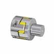
4 Introduction Torsional Stiffness, Flexible Multiple-Disc Couplings GERWAH, Backlash-free Couplings are a 100% steel construction. The flexible portion of this coupling consists of a disc pack developed with the help of FEM analysis made of stainless steel. The steel hubs are connected to the disc packs by means of precision sleeves and highly resilient bolts. Axial misalignment Radial misalignment Depending on customer requirements, the hubs can be attached to the shafts in different ways, e.g. by means of shrink disc or - particularly inexpensive - with locking assemblies. This guarantees a really backlash-free connection of the two shaft ends that is simple and trouble free. The disc packs guarantee high transmissible torques while compensating for axial, radial and angular misalignments. Angular misalignment 4
5 Content 02 Corporate Image 04 Introduction 05 Content 06 Basics Mounting with key 08 Characteristics 10 GERWAH HS 12 GERWAH HD 14 GERWAH HC Mounting with RINGFEDER Shrink Disc 16 Characteristics 18 GERWAH XHS 20 GERWAH XHD 22 GERWAH XHC 24 RINGFEDER RfN 4061 / 4071 Mounting with RINGFEDER Locking Assembly 26 Characteristics 28 GERWAH LHS 30 GERWAH LHD 32 GERWAH LHC 34 Additional Table Mounting with Clamping Hub 36 Characteristics 38 GERWAH CCS 40 GERWAH CCD 42 GERWAH CHS 44 GERWAH CHD 46 GERWAH CHC 48 GERWAH GWL GERWAH GWL GERWAH GWL Technical Information 60 FAX Inquiry 61 Online-Service 62 Product Range RINGFEDER POWER TRANSMISSION * Our special catalogue includes couplings suitable for ATEX / API All technical details and information are non-binding and cannot be used as a basis for legal claims. The user is obligated to determine whether the represented products meet his requirements. We reserve the right at all times to carry out modifications in the interests of technical progress. Upon the issue of this catalogue all previous brochures and questionnaires on the products displayed are no longer valid. In accordance with our policy to constantly improve our products, the spezification herein are subject to change without notice. Please refer to our website for the most up to date information. 5
6 Basics GERWAH : The Advantages of the System 1. No Backlash An important property for synchronous operation or for machines that are frequently used in start/stop or reverse operation. GERWAH Disc Couplings are ideally suited to applications in which the positioning accuracy of the control system in both directions is important. 2. Torsional Stiffness The design of the coupling guarantees a high level of torsional stiffness, which is an important property for applications in packaging machines, servomotors drives, printing presses and machine tools. 5. Long Service Life The highly accurate disc pack insures optimum force distribution, while its flexibility also protects against vibrations from the drive. GERWAH Disc Couplings do not wear, so that a long service life is guaranteed. 6. Maintenance-Free Operation GERWAH Torsionally Rigid Disc Couplings are maintenance-free and do not require greasing or cleaning. 3. High Temperatures GERWAH Rigid Disc Couplings can be used under extreme temperature conditions up to 240 C / 460 F, for example in hightemperature fluid pumps. 7. Installation Position GERWAH Torsionally Rigid Disc Couplings are designed for horizontal installation. In vertical installation situations the spacer may need to be supported (see sketch page 59). 4. High Speeds Due to the very strict production tolerances, GERWAH Rigid Disc allows precise vertical alignment and a high level of true running accuracy, making it ideal for applications involving high speeds even with irregular rotary forces. Application example: Coupling with parasitic current insulation 6


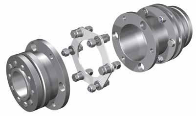
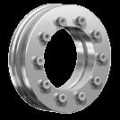
7 Basics General design Disc pack Disc pack Shrink disc Shrink disc Hub Spacer sleeve Hub 6 bolt design Laminated disc pack Higher speeds Angular misalignment 1 per disc pack depending on coupling size Higher torque Compact design Laminated disc pack High speeds Low inertia Low to medium torques Angular misalignment 1 per disc pack depending on coupling size 8 bolt design Medium to high torques 7


8 Characteristics Mounting with key GERWAH HS, HD, HC Multiple-disc coupling for compensating of axial and angular misalignments Versions with 2 disc packs can also be used to compensate for radial misalignments. High torsional stiffness High transmissible torques Can be used up to temperatures of approx. 240 C / 460 F Maintenance-free operation Attachment of the coupling to the shafts with keys Non-standard spacers Many applications for GERWAH Disc Couplings require special spacer lengths and dimensions. We can supply spacers with lengths of up to 195 inch. Higher rotational speeds and / or special couplings A coupling sometimes needs to fulfill certain industrial safety standards or is operated at very high rotational speeds. We can also provide solutions for this. 8


 and are therefore suitable")
9 Characteristics GERWAH HS Coupling without spacer GERWAH HD Coupling with standard spacer GERWAH HC Coupling with short spacer GERWAH Torsionally Rigid Disc Couplings that are installed horizontally are suitable for use in drives in explosion hazard zones. The couplings are assessed and confirmed devices in the category 2G/2D in accordance with the EU directive 94/9/EG (ATEX 95) and are therefore suitable for use in explosion hazard zones G1, G2, D21 and D22. 9

10 Mounting with key GERWAH HS Dimensions d 1k ; d 2kmin = Min. bore diameter with keyway acc. to DIN d 1k ; d 2kmax = Max. bore diameter with keyway acc. to DIN A = Max. outer diameter D 1 = Outer diameter hub L 1 = Length of coupling L 2 = Length on the hub S 1 = Length of disc pack GERWAH HS-75 Dimensions d 1k; d 2k d 1k; d 2k Size min. max. A D 1 L 1 L 2 S 1 inch inch inch inch More sizes on request. Designs with keyway according to DIN / ANSI B Reinforced disc pack on request. Moment of inertia and weight (mass) are calculated with reference to the largest bore size. Ordering example: GERWAH HS Series/Size Bore diameter d 1k Bore diameter d 2k HS
11 L 1 Technical Data A D1 d1k, d2k L 2 S 1 T KN = Nom. transmissible torque T L = Tightening torque of screws in disc pack n max = Max. rotation speed Ka = Max. permissible axial misalignment Kw = Max. permissible angular misalignment Gw = Weight J = Total moment of inertia C Tdyn = Dynamic torsional stiffness Sectional view Technical Data Size T KN T L nmax ΔKa ΔKw Gw J C Tdyn ft-lbs ft-lbs rpm inch degree lbs lbs-in ft-lbs/rad GERWAH Torsionally Rigid Disc Couplings allow at least 1,75 times the nominal torque T KN at d wmax for short periods of time. 11
12 Mounting with key GERWAH HD Dimensions d 1k ; d 2kmin = Min. bore diameter with keyway acc. to DIN d 1k ; d 2kmax = Max. bore diameter with keyway acc. to DIN A = Max. outer diameter D 1 = Outer diameter hub L 1 = Length of coupling L 2 = Length on the hub S 1 = Length of disc pack S 2 = Distance between the shaft ends GERWAH HD-75 Dimensions d 1k; d 2k d 1k; d 2k Size min. max. A D 1 L 1 L 2 S 1 S 2 inch inch inch More sizes on request. Designs with keyway according to DIN / ANSI B Reinforced disc pack on request. Moment of inertia and weight (mass) are calculated with reference to the largest bore size. Ordering example: GERWAH HD Series/Size Bore diameter d 1k Bore diameter d 2k Spacer length S 2 HD
13 Technical Data A D1 d1k, d2k L 2 L 1 S 1 S 2 T KN = Nom. transmissible torque T L = Tightening torque of screws in disc pack n max = Max. rotation speed Ka = Max. permissible axial misalignment Kw = Max. permissible angular misalignment Kr = Max. permissible radial misalignment Gw = Weight J = Total moment of inertia C Tdyn = Dynamic torsional stiffness Sectional view Technical Data Size T KN T L nmax Ka Kw Kr Gw J C Tdyn ft-lbs ft-lbs rpm inch degree inch lbs lbs-in ft-lbs/rad GERWAH Torsionally Rigid Disc Couplings allow at least 1,75 times the nominal torque T KN at d wmax for short periods of time. 13

14 Mounting with key GERWAH HC Dimensions d 1k ; d 2kmin = Min. bore diameter with keyway acc. to DIN d 1k ; d 2kmax = Max. bore diameter with keyway acc. to DIN A = Max. outer diameter D 1 = Outer diameter hub L 1 = Length of coupling L 2 = Length on the hub S 1 = Length of disc pack S 2 = Distance between the shaft ends GERWAH HC-75 Dimensions d 1k; d 2k d 1k; d 2k Size min. max. A D 1 L 1 L 2 S 1 S 2 inch inch inch inch Designs with keyway according to DIN / ANSI B Reinforced disc pack on request. Moment of inertia and weight (mass) are calculated with reference to the largest bore size. Ordering example: GERWAH HC Series/Size Bore diameter d 1k Bore diameter d 2k HC
15 L 1 Technical Data A D1 d1k, d2k L 2 S 1 S 2 T KN = Nom. transmissible torque T L = Tightening torque of screws in disc pack n max = Max. rotation speed Ka = Max. permissible axial misalignment Kw = Max. permissible angular misalignment Kr = Max. permissible radial misalignment Gw = Weight J = Total moment of inertia C Tdyn = Dynamic torsional stiffness Sectional view Technical Data Size T KN T L nmax ΔKa ΔKw ΔKr Gw J C Tdyn ft-lbs ft-lbs rpm inch degree inch lbs lbs-in ft-lbs/rad GERWAH Torsionally Rigid Disc Couplings allow at least 1,75 times the nominal torque T KN at d wmax for short periods of time. 15
 High torsional stiffness Backlash-free")

16 Characteristics Mounting with RINGFEDER Shrink Disc GERWAH XHS, XHD, XHC Multiple-disc coupling for compensating of axial, angular and radial misalignments Permanent backlash-free attachment of the multipledisc coupling by means of RINGFEDER Shrink Disc Overall length adaptable to customer requirements by the use of various center spacers (XHD, XHC) High torsional stiffness Backlash-free transmission of high torques Can be used up to temperatures of approx. 240 C / 460 F Maintenance-free operation Test bench Non-standard spacers Many applications for GERWAH Disc Couplings require special spacer length dimensions. We can supply spacers with lengths of up to 195 inch. Higher rotational speeds and / or special couplings A coupling sometimes needs to fulfill certain industrial safety standards or is operated at very high rotational speeds. We can also provide solutions for this. Pump drive 16


17 Characteristics GERWAH XHS Coupling without spacer GERWAH XHD Coupling with standard spacer GERWAH XHC Coupling with short spacer 17
18 Mounting with RINGFEDER Shrink Disc GERWAH XHS Dimensions d 1 ; d 2min = Min. bore diameter d 1 ; d 2max = Max. bore diameter A = Max. outer diameter L 1 = Length of coupling L 2 = Length on the hub S 1 = Length of disc pack D = Outer diameter shrink disc (page 24-25) d = Inner diameter shrink disc (page 24-25) GERWAH XHS-32 Dimensions d 1 ; d 2 d 1 ; d 2 Size min. max. A 1) L 1 L 2 S 1 inch inch inch inch ) The outer diameter of the shrink disc can be more than the outer diameter of the hub according to the shaft size. 2) Reinforced disc pack on request. Moment of inertia and weight (mass) are calculated with reference to the largest bore size. Ordering example: GERWAH XHS Series/Size Bore diameter d 1 Bore diameter d 2 XHS
19 Technical Data A D d L 1 L 2 S 1 d1,d2 T KN = Nom. Transmissible torque T L = Tightening torque of srews in disc pack n max = Max. rotation speed Ka = Max. permissible axial misalignment Kw = Max. permissible angular misalignment Gw = Weight J = Total moment of inertia C Tdyn = Dynamic torsional stiffness Sectional view Technical Data Size T KN T L nmax ΔKa ΔKw Gw J C Tdyn ft-lbs ft-lbs rpm inch degree lbs lbs-in ft-lbs/rad If the transmissible torque T of the shrink disc is lower than the coupling torque, then the torque T counts maximum coupling torque, see page GERWAH Torsionally Rigid Disc Couplings allow at least 1,75 times the nominal torque T KN at d wmax for short periods of time. Shrink disc dimensions see on page
 d = Inner diameter shrink")
20 Mounting with RINGFEDER Shrink Disc GERWAH XHD Dimensions d 1 ; d 2min = Min. bore diameter d 1 ; d 2max = Max. bore diameter A = Max. outer diameter L 1 = Length of coupling L 2 = Length on the hub S 1 = Length of disc pack S 2 = Distance between the shaft ends D = Outer diameter shrink disc (page 24-25) d = Inner diameter shrink disc (page 24-25) GERWAH XHD-32 Dimensions d 1; d 2 d 1; d 2 Size min. max. A 1) L 1 L 2 S 1 S 2 inch inch inch ) The outer diameter of the shrink disc can be more than the outer diameter of the hub according to the shaft size. Reinforced disc pack on request. Moment of inertia and weight (mass) are calculated with reference to the largest bore size. Ordering example: GERWAH XHD Series/Size Bore diameter d 1 Bore diameter d 2 Spacer length S 2 XHD
21 Technical Data A D d L 1 L 2 S 1 S 2 d1,d2 T KN = Nom. Transmissible torque T L = Tightening torque of srews in disc pack n max = Max. rotation speed Ka = Max. permissible axial misalignment Kw = Max. permissible angular misalignment Kr = Max. permissible radial misalignment Gw = Weight J = Total moment of inertia C Tdyn = Dynamic torsional stiffness Sectional view Technical Data Size T KN T L nmax ΔKa ΔKw ΔKr Gw J C Tdyn ft-lbs ft-lbs rpm inch degree inch lbs lbs-in ft-lbs/rad If the transmissible torque T of the shrink disc is lower than the coupling torque, then the torque T counts maximum coupling torque, see page GERWAH Torsionally Rigid Disc Couplings allow at least 1,75 times the nominal torque T KN at d wmax for short periods of time. Shrink disc dimensions see on page
22 Mounting with RINGFEDER Shrink Disc GERWAH XHC Dimensions d 1 ; d 2min = Min. bore diameter d 1 ; d 2max = Max. bore diameter d 4 = Pilot hole A = Max. outer diameter L 1 = Length of coupling L 2 = Length on the hub S 1 = Length of disc pack S 2 = Distance between the shaft ends D = Outer diameter shrink disc (page 24-25) d = Inner diameter shrink disc (page 24-25) GERWAH XHC-32 Dimensions d 1; d 2 d 1; d 2 Size min. max. d 4 A 1) L 1 L 2 S 1 S 2 inch inch inch inch ) The outer diameter of the shrink disc can be more than the outer diameter of the hub according to the shaft size. Reinforced disc pack on request. Moment of inertia and weight (mass) are calculated with reference to the largest bore size. Ordering example: GERWAH XHC Series/Size Bore diameter d 1 Bore diameter d 2 XHC
23 A D d L 2 S 1 L 1 S 2 d1,d2 Technical Data T KN = Nom. Transmissible torque T L = Tightening torque of srews in disc pack n max = Max. rotation speed Ka = Max. permissible axial misalignment Kw = Max. permissible angular misalignment Kr = Max. permissible radial misalignment Gw = Weight J = Total moment of inertia C Tdyn = Dynamic torsional stiffness Sectional view Technical Data Size T KN T L nmax ΔKa ΔKw ΔKr Gw J C Tdyn ft-lbs ft-lbs rpm inch degree inch lbs lbs-in ft-lbs/rad If the transmissible torque T of the shrink disc is lower than the coupling torque, then the torque T counts maximum coupling torque, see page GERWAH Torsionally Rigid Disc Couplings allow at least 1,75 times the nominal torque T KN at d wmax for short periods of time. Shrink disc dimensions see on page


24 Mounting with RINGFEDER Shrink Disc RINGFEDER RfN 4061/4071 d = Inner diameter D = Outer diameter d w = Solid shaft diameter T = Transmissible torque at given T A L = Overall length L 1 = Overall length without screws Gw = Weight D G = Thread SW = Wrench size T A = Max. tightened torque of the screws RINGFEDER RfN 4061 Shrink Disc Dimensions RfN 4061 / 4071 d D d D d w T L L 1 Gw D G SW T A mm inch ft-lbs inch lbs mm ft-lbs M M M M M M M M M M M M M M M M M M M M M M M M M M M M M M M M
25 L L 1 d D d = Inner diameter D = Outer diameter d w = Solid shaft diameter T = Transmissible torque at given T A L = Overall length L 1 = Overall length without screws Gw = Weight D G = Thread SW = Wrench size T A = Max. tightened torque of the screws Dimensions If the transmissible torque T of the shrink disc is lower than the coupling torque, then the torque T counts as the maximum coupling torque. d D d D d w T L L 1 Gw D G SW T A mm inch ft-lbs inch lbs mm ft-lbs M M M M M M M M M M M M M M M M M M M M M M M M M M M M M M M M


26 Characteristics Mounting with RINGFEDER Locking Assembly GERWAH LHS, LHD, LHC Permanent backlash-free attachment of the multiple-disc coupling by means of RINGFEDER Locking Assemblies Multiple-disc coupling for compensating of axial and angular misalignments. Versions with 2 disc packs can also be used to compensate for radial misalignments. Overall length adaptable to customer requirements by use of various center spacers (LHD, LHC) High torsional stiffness High transmissible torques Can be used up to temperatures of approx. 240 C / 460 F Maintenance-free operation Test bench Non-standard spacers Many applications for GERWAH Disc Couplings require special spacer length dimensions. We can supply spacers with lengths of up to 195 inch. Higher rotational speeds and / or special couplings A coupling sometimes needs to fulfill certain industrial safety standards or is operated at very high rotational speeds. We can also provide solutions for this. Machine tool 26


27 GERWAH LHS, LHD, LHC GERWAH LHS Coupling without spacer GERWAH LHD Coupling with standard spacer GERWAH LHC Coupling with short spacer 27

28 Mounting with RINGFEDER Locking Assembly GERWAH LHS Dimensions d 1 ; d 2min = Min. bore diameter d 1 ; d 2max = Max. bore diameter A = Max. outer diameter D 3 = Outer diameter hub L 1 = Length of coupling L 2 = Length on the hub S 1 = Length of disc pack GERWAH LHS Dimensions d 1; d 2 d 1; d 2 Size min. max. A D 3 L 1 L 2 S 1 inch inch inch inch inch Reinforced disc pack on request. Moment of inertia and weight (mass) are calculated with reference to the largest bore size. Ordering example: GERWAH LHS Series/Size Bore diameter d 1 Bore diameter d 2 LHS
29 A D3 d1, d2 L 1 L 2 S 1 Technical Data T max = Max. transmissible torque T L = Tightening torque of srews in disc pack n max = Max. rotation speed Ka = Max. permissible axial misalignment Kw = Max. permissible angular misalignment Gw = Weight J = Total moment of inertia C Tdyn = Dynamic torsional stiffness Sectional view Technical Data Size T 1) max T L nmax ΔKa ΔKw Gw J C Tdyn ft-lbs ft-lbs rpm inch degree lbs lbs-in ft-lbs/rad ) transmissible torque, depending on size of shaft fixing, is less than or equal to T max. GERWAH Torsionally Rigid Disc Couplings allow at least 1,75 times the nominal torque T KN at d wmax for short periods of time. Torque is limited by the locking device capacity of the smallest shaft, see page 34 and

30 Mounting with RINGFEDER Locking Assembly GERWAH LHD Dimensions d 1 ; d 2min = Min. bore diameter d 1 ; d 2max = Max. bore diameter A = Max. outer diameter D 3 = Outer diameter hub L 1 = Length of coupling L 2 = Length on the hub S 1 = Length of disc pack S 2 = Distance between the shaft ends GERWAH LHD Dimensions d 1; d 2 d 1; d 2 Size min. max. A D 3 L 1 L 2 S 1 S 2 inch inch inch inch Reinforced disc pack on request. Moment of inertia and weight (mass) are calculated with reference to the largest bore size. Ordering example: GERWAH LHD Series/Size Bore diameter d 1 Bore diameter d 2 Spacer length S 2 LHD
31 L 1 Technical Data A D3 d1, d2 L 2 S 1 S 2 T max = Max. transmissible torque T L = Tightening torque of srews in disc pack n max = Max. rotation speed Ka = Max. permissible axial misalignment Kw = Max. permissible angular misalignment Kr = Max. permissible radial misalignment Gw = Weight J = Total moment of inertia C Tdyn = Dynamic torsional stiffness Sectional view Technical Data Size T 1) max T L nmax ΔKa ΔKw ΔKr Gw J C Tdyn ft-lbs ft-lbs rpm inch degree inch lbs lbs-in ft-lbs/rad ) transmissible torque, depending on size of shaft fixing, is less than or equal to T max. GERWAH Torsionally Rigid Disc Couplings allow at least 1,75 times the nominal torque T KN at d wmax for short periods of time. Torque is limited by the locking device capacity of the smallest shaft, see page 34 and

32 Mounting with RINGFEDER Locking Assembly GERWAH LHC Dimensions d 1 ; d 2min = Min. bore diameter d 1 ; d 2max = Max. bore diameter A = Max. outer diameter D 3 = Outer diameter hub L 1 = Length of coupling L 2 = Length on the hub S 1 = Length of disc pack S 2 = Distance between the shaft ends GERWAH LHC Dimensions d 1; d 2 d 1; d 2 Size min. max. A D 3 L 1 L 2 S 1 S 2 inch inch inch inch Reinforced disc pack on request. Moment of inertia and weight (mass) are calculated with reference to the largest bore size. Ordering example: GERWAH LHC Series/Size Bore diameter d 1 Bore diameter d 2 LHC
33 L 1 Technical Data A D3 d1, d2 L 2 S 1 S 2 T max = Max. transmissible torque T L = Tightening torque of srews in disc pack n max = Max. rotation speed Ka = Max. permissible axial misalignment Kw = Max. permissible angular misalignment Kr = Max. permissible radial misalignment Gw = Weight J = Total moment of inertia C Tdyn = Dynamic torsional stiffness Sectional view Technical Data Size T 1) max T L nmax ΔKa ΔKw ΔKr Gw J C Tdyn ft-lbs ft-lbs rpm inch degree inch lbs lbs-in ft-lbs/rad ) transmissible torque, depending on size of shaft fixing, is less than or equal to T max. GERWAH Torsionally Rigid Disc Couplings allow at least 1,75 times the nominal torque T KN at d wmax for short periods of time. Torque is limited by the locking device capacity of the smallest shaft, see page 34 and
34 Mounting with RINGFEDER Locking Assembly Additional Table Locking Device Torque Capacity by Coupling and Shaft Size Use the table below to verify if the coupling max. torque capacity is limited by the shaft size. The coupling torque capacity will be the smaller number from the coupling and shaft table. Dimensions and Technical Data D G = Thread SW = Wrench size T A = Max. tightened torque of the screws Ø = Transmissible torque, depending on bore diameter d 1, d 2 = Bore diameter Ø mm Ø inch Size D G SW T A mm ft-lbs ft-lbs M M M M M M Example: Size with bore inch transmissible torque: 85 ft-lbs Example: Size with bore inch transmissible torque: 752 ft-lbs Torque is limited by the locking device capacity of the smallest shaft 34
35 GERWAH LHS, LHD, LHC L 1 L 2 S 1 Dimensions and Technical Data D G = Thread SW = Wrench size T A = Max. tightened torque of the screws Ø = Transmissible torque, depending on bore diameter d 1, d 2 = Bore diameter A D3 d1, d2 Sectional view Ø mm Ø inch Size D G SW T A mm ft-lbs ft-lbs M M M M d 1 Bore = inch d 2 Bore = inch Torque is limited by the locking device capacity of the smallest shaft 35

36 Characteristics Mounting with Clamping Hub GERWAH CCS, CCD Coupling with axial, angular and parallel (CCD) misalignment capability Low inertia, high speeds Minimized dimensions Can be used up to temperatures of approx. 240 C / 460 F Maintenance-free operation GERWAH CHS, CHD, CHC Coupling for compensating of axial, angular and radial (CHD and CHC) misalignments Permanent backlash-free attachment of the disc coupling by means of clamping hub Overall length adaptable to customer requirements by use of different spacer sleeves (CHD) or very short length with close coupled sleeve (CHC) High torsional stiffness Backlash-free transmission of high torques Can be used up to temperatures of approx. 240 C / 460 F Maintenance-free operation Machine tool Higher rotational speeds and / or special couplings A coupling sometimes needs to fulfill certain industrial safety standards or is operated at very high rotational speeds. We can also provide solutions for this. Non-standard spacers Many applications with GERWAH Couplings require special spacer length dimensions. We can supply spacers with lengths of up to 195 inch. GERWAH GWL , , Disc Coupling in split hub design Half-shell GERWAH multi-plate clutches can fit in the smallest installation spaces as no axial displacement of the clutch is necessary for assembly and disassembly. This achieves a substantial reduction in assembly time. GERWAH half shell multi-plate clutches can also be precisely aligned to one another, reducing the risk of alignment errors. 36


37 Characteristics GERWAH CCS Aluminum Clamping Hub Coupling without spacer GERWAH CCD Aluminum Clamping Hub Coupling with standard spacer GERWAH CHS Clamping Hub Coupling without spacer GERWAH CHD Clamping Hub Coupling with standard spacer GERWAH CHC Clamping Hub Coupling with short spacer GERWAH GWL Clamping Hub Coupling without spacer in split hub design GERWAH GWL Clamping Hub Coupling with standard spacer in split hub design GERWAH GWL Clamping Hub Coupling with short spacer in split hub design 37
 = Clearance diameter 2 (screw is bigger when using small shafts) K = Distance shaft axis - clamping screw axis L 1 = Length of coupling L 2 = Length on the")
38 Mounting with Clamping Hub GERWAH CCS Dimensions d 1 ; d 2min = Min. bore diameter d 1 ; d 2max = Max. bore diameter A = Max. outer diameter H = Clearance diameter H (2) = Clearance diameter 2 (screw is bigger when using small shafts) K = Distance shaft axis - clamping screw axis L 1 = Length of coupling L 2 = Length on the hub S 1 = Length of disc pack GERWAH CCS-17 Dimensions d 1; d 2 d 1; d 2 Size min. max. A H H (2) K L 1 L 2 S 1 inch inch inch inch inch Optional designs with keyway according to DIN / ANSI B Reinforced disc pack on request. Moment of inertia and weight (mass) are calculated with reference to the largest bore size. Shaft diameter inch h7 Shaft tolerance inch up to up to > / Ordering example: GERWAH CCS Series/Size Bore diameter d 1 Bore diameter d 2 CCS > / > / > / > /
39 Compact design Technical Data A d1 L 1 L 2 L 2 d2 H, H (2) K T KN = Nom. transmissible torque T L = Tightening torque of srews in disc pack T A = Max. tightened torque of the screws n max = Max. rotation speed Ka = Max. permissible axial misalignment Kw = Max. permissible angular misalignment Gw = Weight J = Total moment of inertia C Tdyn = Dynamic torsional stiffness D G1 S 1 Sectional view Technical Data Gw Size T KN T L nmax ΔKa ΔKw J C Tdyn ft-lbs ft-lbs rpm inch degree lbs lbs-in ft-lbs/rad GERWAH Torsionally Rigid Disc Couplings allow at least 1,75 times the nominal torque T KN at d wmax for short periods of time. Transmissible torques d 1 ; d 2 Ø mm Ø inch Ø14 Ø15 Ø16 Ø18 Ø19 Ø20 Ø22 Ø24 Ø25 Ø28 Ø30 Ø32 Ø35 Ø38 Ø40 Ø42 Ø45 Ø48 Ø50 Ø55 Ø60 Size T A 9 ft-lbs 81 (M8) 88 (M8) 96 (M8) 110 M8) 66 (M6) 74 (M6) 81 (M6) 88 (M6) 96 (M6) 103 (M6) 110 (M6) (M6) / 24 (M8) 17 ft-lbs (M8) 184 (M8) 199 (M8) 221 (M8) 236 (M8) 250 (M8) (M8) / ft-lbs (M8) 295 (M8) 317 (M8) 346 (M8) 369 (M8) 24 (M8) / 48 39
 = Clearance diameter 2 (screw is bigger when using small shafts) K = Distance shaft axis - clamping screw axis L 1 = Length of coupling L 2 = Length on the")
40 Mounting with Clamping Hub GERWAH CCD Dimensions d 1 ; d 2min = Min. bore diameter d 1 ; d 2max = Max. bore diameter A = Max. outer diameter H = Clearance diameter H (2) = Clearance diameter 2 (screw is bigger when using small shafts) K = Distance shaft axis - clamping screw axis L 1 = Length of coupling L 2 = Length on the hub S 1 = Length of disc pack S 2 = Distance between the shaft ends GERWAH CCD-32 Dimensions d 1; d 2 d 1; d 2 Size min. max. A H H (2) K L 1 L 2 S 1 S 2 inch inch inch inch inch Optional designs with keyway according to DIN / ANSI B Reinforced disc pack on request. Moment of inertia and weight (mass) are calculated with reference to the largest bore size. Shaft diameter inch h7 Shaft tolerance inch up to up to > / Ordering example: GERWAH CCD Series/Size Bore diameter d 1 Bore diameter d 2 CCD > / > / > / > /
41 Compact design Technical Data A d1 L 1 L 2 S 2 L 2 d2 H, H (2) K T KN = Nom. transmissible torque T L = Tightening torque of srews in disc pack T A = Max. tightened torque of the screws n max = Max. Drehzahl/Max. rotation speed Ka = Max. permissible axial misalignment Kw = Max. permissible angular misalignment Kr = Max. permissible radial misalignment Gw = Weight J = Total moment of inertia C Tdyn = Dynamic torsional stiffness D G1 S 1 Sectional view Technical Data Gw Size T KN T L nmax ΔKa ΔKw ΔKr J C Tdyn ft-lbs ft-lbs rpm inch degree inch lbs lbs-in ft-lbs/rad GERWAH Torsionally Rigid Disc Couplings allow at least 1,75 times the nominal torque T KN at d wmax for short periods of time. Transmissible torques d 1 ; d 2 Ø mm Ø inch Size T A 9 ft-lbs 81 (M8) 88 (M8) 96 (M8) 110 (M8) 66 (M6) 74 (M6) 81 (M6) 88 (M6) 96 (M6) 103 (M6) 110 (M6) (M6) / 24 (M8) 17 ft-lbs (M8) 184 (M8) 199 (M8) 221 (M8) 236 (M8) 250 (M8) (M8) / ft-lbs (M8) 295 (M8) 317 (M8) 346 (M8) 369 (M8) 24 (M8) / 48 41

42 Mounting with Clamping Hub GERWAH CHS Dimensions d 1 ; d 2min = Min. bore diameter d 1 ; d 2max = Max. bore diameter d 4 = Pilot hole A = Max. outer diameter D 1 = Outer diameter hub L 1 = Length of coupling L 2 = Length on the hub S 1 = Length of disc pack GERWAH CHS-32 Dimensions d 1; d 2 d 1; d 2 Size min. max. d 4 A D 1 L 1 L 2 S 1 inch inch inch inch Reinforced disc pack on request. Moment of inertia and weight (mass) are calculated with reference to the largest bore size. Shaft diameter inch h7 Shaft tolerance inch up to up to > / Ordering example: GERWAH CHS Series/Size Bore diameter d 1 Bore diameter d 2 CHS > / > / > / > /
43 Technical Data A D1 d1, d2 L2 L 1 S1 T KN = Nom. transmissible torque T L = Tightening torque of srews in disc pack T A = Max. tightened torque of the screws n max = Max. rotation speed Ka = Max. permissible axial misalignment Kw = Max. permissible angular misalignment Gw = Weight J = Total moment of inertia C Tdyn = Dynamic torsional stiffness Sectional view Technical Data Size T KN T L nmax ΔKa ΔKw Gw J C Tdyn ft-lbs ft-lbs rpm inch degree lbs lbs-in ft-lbs/rad GERWAH Torsionally Rigid Disc Couplings allow at least 1,75 times the nominal torque T KN at d wmax for short periods of time. Transmissible torques d 1 ; d 2 Ø mm Ø inch Size T A (M6) (M8)
44 Mounting with Clamping Hub GERWAH CHD Dimensions d 1 ; d 2min = Min. bore diameter d 1 ; d 2max = Max. bore diameter d 4 = Pilot hole A = Max. outer diameter D 1 = Outer diameter hub L 1 = Length of coupling L 2 = Length on the hub S 1 = Length of disc pack S 2 = Distance between the shaft ends GERWAH CHD-32 Dimensions d 1; d 2 d 1; d 2 Size min. max. d 4 A D 1 L 1 L 2 S 1 S 2 inch inch inch Reinforced disc pack on request. Moment of inertia and weight (mass) are calculated with reference to the largest bore size. Shaft diameter inch h7 Shaft tolerance inch up to up to > / Ordering example: GERWAH CHD Series/Size Bore diameter d 1 Bore diameter d 2 Spacer length S 2 CHD > / > / > / > /
45 Technical Data A D1 d1, d2 L2 S1 L 1 S2 T KN = Nom. transmissible torque T L = Tightening torque of srews in disc pack T A = Max. tightened torque of the screws n max = Max. rotation speed Ka = Max. permissible axial misalignment Kw = Max. permissible angular misalignment Kr = Max. permissible radial misalignment Gw = Weight J = Total moment of inertia C Tdyn = Dynamic torsional stiffness Sectional view Technical Data Size T KN T L nmax ΔKa ΔKw ΔKr Gw J C Tdyn ft-lbs ft-lbs rpm inch degree inch lbs lbs-in ft-lbs/rad GERWAH Torsionally Rigid Disc Couplings allow at least 1,75 times the nominal torque T KN at d wmax for short periods of time. Transmissible torques d 1 ; d 2 Ø mm Ø inch Size T A (M6) (M8)
46 Mounting with Clamping Hub GERWAH CHC Dimensions d 1 ; d 2min = Min. bore diameter d 1 ; d 2max = Max. bore diameter d 4 = Pilot hole A = Max. outer diameter D 1 = Outer diameter hub L 1 = Length of coupling L 2 = Length on the hub S 1 = Length of disc pack S 2 = Distance between the shaft ends GERWAH CHC-32 Dimensions d 1; d 2 d 1; d 2 Size min. max. d 4 A D 1 L 1 L 2 S 1 S 2 inch inch inch inch Reinforced disc pack on request. Moment of inertia and weight (mass) are calculated with reference to the largest bore size. Shaft diameter inch h7 Shaft tolerance inch up to up to > / Ordering example: GERWAH CHC Series/Size Bore diameter d 1 Bore diameter d 2 CHC > / > / > / > /
47 L 1 Technical Data L2 S 1 S 2 T KN T L = Nom. transmissible torque = Tightening torque of srews in disc pack T A = Max. tightened torque of the screws n max = Max. rotation speed Ka = Max. permissible axial misalignment Kw = Max. permissible angular misalignment A D1 d1, d2 Kr Gw J = Max. permissible radial misalignment = Weight = Total moment of inertia C Tdyn = Dynamic torsional stiffness Sectional view Technical Data Size T KN T L nmax ΔKa ΔKw ΔKr Gw J C Tdyn ft-lbs ft-lbs rpm inch degree inch lbs lbs-in ft-lbs/rad GERWAH Torsionally Rigid Disc Couplings allow at least 1,75 times the nominal torque T KN at d wmax for short periods of time. Transmissible torques d 1 ; d 2 Ø mm Ø inch Size T A 17 ft-lbs (M6) 32 ft-lbs (M8) 75 ft-lbs ft-lbs

48 Mounting with Clamping Hub GERWAH GWL Dimensions d 1 ; d 2min = Min. bore diameter d 1 ; d 2max = Max. bore diameter d 4 = Pilot hole A = Max. outer diameter D 1 = Outer diameter hub DB SE = Distance between shaft ends L 1 = Length of coupling L 2 = Length on the hub S 1 = Length of disc pack GERWAH GWL d 1; d 2 d 1; d 2 Size min. max. d 4 A D 1 DB SE L 1 L 2 S 1 inch inch inch inch inch Reinforced disc pack on request. Moment of inertia and weight (mass) are calculated with reference to the largest bore size. Shaft diameter inch h7 Shaft tolerance inch up to up to > / Ordering example: GERWAH GWL Series/Size Bore diameter d 1 Bore diameter d 2 GWL > / > / > / > /
49 L 1 Technical Data A D1 d1, d2 L 2 S 1 DB SE T KN = Nom. transmissible torque T max = Max. transmissible torque T L = Tightening torque of srews in disc pack n max = Max. rotation speed Ka = Max. permissible axial misalignment Kw = Max. permissible angular misalignment Gw = Weight J = Total moment of inertia C Tdyn = Dynamic torsional stiffness T AM5 = Tightening torque of screw M5 T AM6 = Tightening torque of screw M6 T AM8 = Tightening torque of screw M8 T AM10 = Tightening torque of screw M10 Sectional view Size T KN T max T L nmax Ka Kw Gw J C Tdyn ft-lbs ft-lbs ft-lbs rpm inch degree lbs lbs-in ft-lbs/rad GERWAH Torsionally Rigid Disc Couplings allow at least 1,75 times the nominal torque T KN at d wmax for short periods of time. Transmissible torques Size d 1 ; d 2 mm (2) T A Ø15 Ø16 Ø18 Ø19 Ø20 Ø22 Ø24 Ø25 Ø28 Ø30 Ø32 Ø35 Ø38 Ø40 Ø42 Ø45 Ø48 Ø50 Ø55 Ø60 Ø65 M5 M6 M8 M
50 Mounting with Clamping Hub GERWAH GWL Dimensions d 1 ; d 2min = Min. bore diameter d 1 ; d 2max = Max. bore diameter d 4 = Pilot hole A = Max. outer diameter D 1 = Outer diameter hub DB SE = Distance between shaft ends L 1 = Length of coupling L 2 = Length on the hub S 1 = Length of disc pack S 2 = Distance between the shaft ends GERWAH GWL d 1; d 2 d 1; d 2 Size min. max. d 4 A D 1 DB SE L 1 L 2 S 1 S 2 inch inch inch inch Reinforced disc pack on request. Moment of inertia and weight (mass) are calculated with reference to the largest bore size. Shaft diameter inch h7 Shaft tolerance inch up to up to > / > / > / > / Ordering example: GERWAH GWL > / Series / Size Bore diameter d 1 Bore diameter d 2 Spacer length S 2 GWL
51 Technical Data L 1 A D1 d1, d2 L 2 S 1 S 2 DB SE T KN = Nom. transmissible torque T max = Max. transmissible torque T L = Tightening torque of srews in disc pack n max = Max. rotation speed Ka = Max. permissible axial misalignment Kw = Max. permissible angular misalignment Kr = Max. permissible radial misalignment Gw = Weight J = Total moment of inertia C Tdyn = Dynamic torsional stiffness T AM5 = Tightening torque of screw M5 T AM6 = Tightening torque of screw M6 T AM8 = Tightening torque of screw M8 T AM10 = Tightening torque of screw M10 Sectional view Gw Size T KN T max T L nmax Ka Kw Kr J C Tdyn ft-lbs ft-lbs ft-lbs rpm inch degree inch lbs lbs-in ft-lbs/rad GERWAH Torsionally Rigid Disc Couplings allow at least 1,75 times the nominal torque T KN at d wmax for short periods of time. Transmissible torques Size d 1 ; d 2 mm (2) T A Ø15 Ø16 Ø18 Ø19 Ø20 Ø22 Ø24 Ø25 Ø28 Ø30 Ø32 Ø35 Ø38 Ø40 Ø42 Ø45 Ø48 Ø50 Ø55 Ø60 Ø65 M5 M6 M8 M

52 Mounting with Clamping Hub GERWAH GWL Dimensions d 1 ; d 2max = Max. bore diameter d 4 = Pilot hole A = Max. outer diameter D 1 = Outer diameter hub DB SE = Distance between shaft ends L 1 = Length of coupling L 2 = Length on the hub S 1 = Length of disc pack S 2 = Distance between the shaft ends GERWAH GWL d 1; d 2 d 1; d 2 Size min. max. d 4 A D 1 DB SE L 1 L 2 S 1 S 2 inch inch inch inch inch Reinforced disc pack on request. Moment of inertia and weight (mass) are calculated with reference to the largest bore size. Shaft diameter inch h7 Shaft tolerance inch up to up to > / Ordering example: GERWAH GWL Series/Size Bore diameter d 1 Bore diameter d 2 GWL > / > / > / > /
53 L 1 Technical Data A D1 d1, d2 L 2 S 1 S 2 DB SE T KN = Nom. transmissible torque T max = Max. transmissible torque T L = Tightening torque of srews in disc pack n max = Max. rotation speed Ka = Max. permissible axial misalignment Kw = Max. permissible angular misalignment Kr = Max. permissible radial misalignment Gw = Weight J = Total moment of inertia C Tdyn = Dynamic torsional stiffness T AM5 = Tightening torque of screw M5 T AM6 = Tightening torque of screw M6 T AM8 = Tightening torque of screw M8 T AM10 = Tightening torque of screw M10 Sectional view Size T KN T max T L nmax Ka Kw Kr Gw J C Tdyn ft-lbs ft-lbs ft-lbs rpm inch degree inch lbs lbs-in ft-lbs/rad GERWAH Torsionally Rigid Disc Couplings allow at least 1,75 times the nominal torque T KN at d wmax for short periods of time. Transmissible torques Size d 1 ; d 2 mm (2) T A Ø15 Ø16 Ø18 Ø19 Ø20 Ø22 Ø24 Ø25 Ø28 Ø30 Ø32 Ø35 Ø38 Ø40 Ø42 Ø45 Ø48 Ø50 Ø55 Ø60 Ø65 M5 M6 M8 M
54 Technical Information Selection Guide The selection of the coupling size depends entirely on the torque to be transmitted and required shaft sizes. However, for the selection of the coupling type, application conditions (e.g., shaft misalignments, expansions and operating speeds) must be taken into consideration. For any special applications, please consult with us. When selecting a coupling size, make sure that under all operating conditions its torque capacity and speed range are not exceeded. 1. Calculate the driving torque (T AN ) to be transmitted from T AN (in-lbs) = HP/RPM T AN (Nm) = 9550 KW/RPM 2. Determine required coupling nominal torque capacity (T KN ) by finding the appropriate service factor (SM) in Table 1 for your application. Multiply the torque calculated above (T AN ) by this service factor. T KN (in-lbs) = T AN SM Find T KN in coupling data sheets that is larger than the calculated T KN. This will be correct size of the coupling. NOTE: GERWAH Torsionally Rigid Disc Couplings can transmit higher torques for a short period of time without having to consider an additional service factor. Please consult coupling data sheets for maximum torque values. 3. Check if existing or predicted axial, angular and radial misalignments are within permissible values as shown in the catalog. If any one of the misalignments is close to the maximum allowable, the maximum misalignment in the other directions and the torque capacity will be effected. For this reason, we recommend selecting a coupling with more misalignment capacity than required. See empirical formula: DK r 100% + DK r 4. Verify the maximum hub bore and speed required. Do not exceed the maximum values for the coupling. NOTE: For a given hub size, larger shafts can be used with the RINGFEDER Shrink Disc rather than with traditional keyed connections. 5. If the RINGFEDER Shrink Disc or Locking Assembly connection is used, verify the torque capacity of the locking device connection is less than the couplings torque capacity. The locking device torque capacities for each shaft size can be found in the appropriate catalog. 6. Use Fig. 1 to verify if your coupling does or does not need to be dynamically balanced. 54 (Installation situation) (Data sheet) DK a DK w 100% + DK a 100% < 100% DK w Fig. 1 The balancing class of the standard elements is Q6,3 - VDI 2060 medium speeds. Balancing is recommended only over speed curve of Fig. 1. Operating factor SM Electric motors Piston engines Piston engines Turbines with more than with 1 or 2 Hydraulic motors 2 zylinders zylinders Building construction machines 2,1 2,5 3 Chemical industry Agiators (semi-liquid material) 1,7 2,1 2,6 Agiators (liquid material) 1 1,4 1,7 Centrifuges 1,35 1,75 2,2 Pipeline pumps 1,7 2,1 2,6 Conveyors and lifts Goods lifts 1,7 2,1 2,6 Passenger lifts 1,7 2,1 2,6 Belt conveyors 1,7 2,1 2,6 Blowers, ventilators 1,35 1,75 2,2 Generators, transformers 1 1,4 1,7 Wood-plastic industry machinery Planing machines 1,7 2,1 2,6 Woodworking machines 1 1,4 1,7 Mixers 1,7 2,1 2,6 Extruders 1,7 2,1 2,6 Cranes 1,7 2,1 2,6 Metal working machines Presses 2,4 2,8 3,3 Machine tools 1,7 2,1 2,6 Food industry machinery Kneading machines 1,7 2,1 2,6 Mills 2,4 2,8 3,3 Packaging machines 1 1,4 1,7 Paper machines Pulp grinders 2,4 2,8 3,3 Shredder 2,4 2,8 3,3 Presses, rolls 2,4 2,8 3,3 Calenders 1,7 2,1 2,6 Pumps Piston pumps 2,4 2,8 3,3 Centrifugal pumps 1,35 1,75 2,2 Stone and clay working machines Mills, breakers 2,4 2,8 3,3 Rotary ovens 2,4 2,8 3,3 Textile machines Looms 1,7 2,1 2,6 Winders 1,7 2,1 2,6 Compressors Piston compressors 2,4 2,8 3,3 Turbo compressors 1,7 2,1 2,6 Metal rolling mills Shears 2,4 2,8 3,3 Plate-mill lines 2,4 2,8 3,3 Cold rolling mills 2,4 2,8 3,3 Rolling mill adjusters 1,7 2,1 2,6 Winding machines 1,7 2,1 2,6 Continous casting plant 2,4 2,8 3,3 Laundries 1,7 2,1 2,6 Table 1: Operating factor (SM)
55 Technical Information GERWAH Disc Coupling installation instructions TOOLS REQUIRED: Torque wrench and sockets for shrink disc, locking assembly and coupling hex bolts (see tables page 57) Open end wrench for coupling hex bolts Straight edge and/or dial indicator Feeler gauges THESE INSTRUCTIONS ARE FOR STANDARD COUP-LINGS WITH NORMAL RUNNING CONDITIONS. ALL COUPLINGS SHIPPED LOOSELY ASSEMBLED. BOLTS MUST BE TORQUED PRIOR TO USE. SEE PAGE 57. Fig. 2: Hub configuration for shrink disc connection It is recommended to disassemble the coupling for easier installation. Note page 58 for the correct arrangement of the bolts, washers, disc pack, and nuts. Shrink disc 1 S1 Shrink disc 2 Attachment to the shaft Shrink Disc (XHS, XHD, XHC) 1. Inspect both driving and driven shafts making sure they are clean and free from burrs. Lightly oil shaft and hub bore. 2. Place first hub with shrink disc on one shaft and the second hub on the other shaft. Slide them back so that both shaft ends are visible. min. = S2 min. = S2 + x 3. Move first hub to be flush with shaft end. Gradually tighten all shrink disc locking screws, in several passes, to specified tightening torque (T A ); see page 24/25. Shrink disc is not fully installed until one pass is completed without any bolts turning. Use torque wrench! For in-depth instructions, see appropriate catalogue. 4. Follow instructions for axial alignment and then fit second hub to shaft as explained in step 3, see table on page Fig. 3: Single flexing Shrink disc 1 S2 Shrink disc 2 Attachment to shaft Locking Assembly (LHS, LHD, LHC) 1. Inspect both driving and driven shafts making sure they are clean and free from burrs. Lightly oil shaft and hub bore. DO NOT USE MOLYBDENUM DISULFIDE BASED PRODUCTS. min. = S2 min. = S2 + x 2. Place the first hub with locking assembly on one shaft and the second hub on the other shaft. Slide them on so that the shaft ends are exposed. Fig. 4: Double flexing 55
56 Technical Information 3. Follow instructions for axial alignment and then fit the second hub to shaft as explained in step 3. Again, be sure that the locking assembly is fully supported by the shaft. 4. Move the first hub so that locking assembly is completely on and supported by the shaft. Gradually tighten all locking assembly screws, in several passes, to the specified tightening torque (T A, see table, page 34/35). Locking assembly is not fully installed until one pass is completed without bolts turning. Use a torque wrench! Attachment to the shaft keyway (HS, HD, HC) 1. Inspect shaft and hub bores and keyways to make sure that they are clean and free of burrs. Lightly oiling the shaft will also make it easier to assemble. 2. Place the first hub on one shaft and the second hub on the second shaft. Slide them until shaft ends are visible. 3. Hubs are supplied standard with a slight clearance fit. Interference fits would be recommended for bores larger than 3. For more information, please contact our technical department. 4. Move hubs to be flush with end of the shaft. Hubs will last longest when the key is engaged for the full length of the hub. 5. Fit key into hub and turn set screw until top of key is contacted in the hub. 6. Follow instructions for axial alignment and then secure second hub to shaft as explained in steps 4 and 5. Dimensions (inch) Shaft - diameter Width Height Depth Tolerance Depth Tolerance d b* h t 1 t 2 >0,394 to 0,472 0,157 0,157 0,098 0,004 0,071 0,004 >0,472 to 0,669 0,197 0,197 0,118 0,004 0,091 0,004 >0,669 to 0,866 0,236 0,236 0,138 0,004 0,110 0,004 >0,866 to 1,181 0,315 0,276 0,157 0,008 0,130 0,008 >1,181 to 1,496 0,394 0,315 0,197 0,008 0,130 0,008 >1,496 to 1,732 0,472 0,315 0,197 0,008 0,130 0,008 >1,732 to 1,969 0,551 0,354 0,217 0,008 0,150 0,008 >1,969 to 2,283 0,63 0,394 0,236 0,008 0,169 0,008 >2,283 to 2,559 0,709 0,433 0,276 0,008 0,173 0,008 >2,559 to 2,953 0,787 0,472 0,295 0,008 0,193 0,008 >2,953 to 3,346 0,866 0,551 0,354 0,008 0,213 0,008 >3,346 to 3,740 0,984 0,551 0,354 0,008 0,213 0,008 >3,740 to 4,331 1,102 0,63 0,394 0,008 0,252 0,008 >4,331 to 5,118 1,260 0,709 0,433 0,008 0,291 0,008 >5,118 to 5,906 1,417 0,787 0,472 0,012 0,331 0,012 Table 2 according to DIN / ANSI B *Tolerance of b JS9 or P9. Attachment to shaft clamping hub (CCS, CCD, CHS, CHD, CHC) 1. Inspect both driving and driven shafts making sure they are clean and free from burrs. Lightly oil shaft and hub bore. DO NOT USE MOLYBDENUM DISULFIDE BASED PRODUCTS. 2. Place hubs on shafts. Move first hub flush with the end of the hub (Fig. 3 and Fig. 4 page 55). Tighten the respective coupling with the tightening torques T A listed in the table. Use a torque wrench! 3. Follow instructions for adjusting axial alignment and then fit the second hub as explained in step 4. b t2 4. Repeat step 2 for second hub. Be sure shaft is completely covered by clamping portion of hub. d - t1 d + t2 h t1 d Keyway joint to DIN / ANSI B
57 Technical Information Machinery Alignment The life of the coupling is directly affected by the alignment accuracy of the two coupling halves. Careful initial alignment will allow the coupling to operate at full capacity and tolerate for some future operational misalignments (i.e. equipment settling). For this reason, the maximum misalignment values given in the next tables are 30% of the maximum values for the coupling. Keeping all three directions of misalignment within these limits will increase the coupling life. Shaft diameter h7 Shaft tolerance inch inch / / / / / / Table 3: Standard shaft tolerances h7 Axial Alignment 1. Bring components into the best visual alignment possible. Position the hubs axially so that the distance between shaft ends is within min. and max. dimensions S 1 (single flexing) and S 2 (double flexing) for standard couplings. See figures 3 and 4, page 55. For non-standard couplings, check corresponding coupling drawing. 2. Now position first hub so that the shaft end is flush with the hub face and lock in place. Please see pertinent Attachment to the shaft instructions on page Slide second hub into position axially using the S 1 (single flexing) or S 2 (double flexing). S 1 S 2 +/- U r T L Hex or mm mm mm mm mm Nm socket 1) Size axial angular parallel Bolt information 2) 17 0,299 2,36 0,012 0,012 0,012 5,9 4 mm 32 0,346 2,76 0,012 0,012 0, mm 75 0,409 3,94 0,012 0,020 0, mm 135 0,472 3,94 0,012 0,024 0, mm 240 0,512 5,51 0,020 0,028 0,020 81,0 18 mm 400 0,591 5,51 0,020 0,031 0, mm 650 0,819 7,09 0,020 0,035 0, mm Parallel (Radial) Alignment 1. Initial parallel alignment can be checked by using a straight-edge across the hub flanges (per Fig. 6, page 58) to measure the approx. distance (r) as shown in Table 4. Use a more precise method by using a dial indicator the parallel off-set is measured in at least two places 90 degrees apart while rotating one hub. This is shown in Fig. 7, page ,102 9,84 0,012 0,031 0, mm ,268 9,84 0,020 0,035 0, mm Table 4: Alignment values and coupling bolt information 1) Wrench sizes hexagon, 2) Applies to screws in the disc pack 2. Adjust or shim equipment to bring indicator reading within max. allowable parallel misalignment (r) per Table 4. 57
58 Technical Information Installing Disc Pack and Sleeve S 1 U 1. Once the hubs are aligned in the axial, angular and parallel directions, install the disc pack and sleeve. Figure 8 shows the hardware orientation for each coupling type. 2. Tighten the coupling bolts to the prescribed tightening torque (T L ) (see page 57, table 4). Use a torque wrench for this purpose, in order to ensure the necessary tightening torque. 3. It is useful to check the alignment one last time before finally fixing the coupling. To do this measure the height of the disc pack S1 at two positions at 180 degrees to one another (fig. 5). The difference between the two measured values may not exceed the value U (page 57, table 4). Fig. 5 CAUTION: All rotating equipment is potentially dangerous and must be properly guarded. It is the user s responsibility to check for all applicable safety codes and provide suitable guards and protection. All protective shields must be mounted and tested for clearance before initial operation. Fig. 6 Fig. 7 only size 17 and 32 Fig. 8: Hardware arrangement 58


 GD coupling with special spacer for printing press application Higher Speed or Special Couplings Fig.")

59 Technical Information Misalignment and Misalignment Factor f1 The maximum misalignments stated in the tables only apply if they occur individually. If there is a combination of misalignments, the permitted individual misalignments are reduced accordingly. The combined total angular misalignment D tot is a function of the angular misalignment angular and offset misalignment radial of the shafts, according to the following formula: Non-Standard Spacers Many GERWAH Disc Coupling applications require special spacer lengths and dimensions. At RINGFEDER, we can offer spacer lengths up to 195 inch. tot [ ] = angular 2 +arctan radial (S 2 - S 1 ) GD coupling with special spacer for printing press application Higher Speed or Special Couplings Fig. 10 If a coupling needs to meet more demanding industrial standards in safety, or will be operated at higher speeds, RINGFEDER has a solution. Please contact our Engineering Department. f Fig HD coupling that meets API 610 Temperature Factor f 3 GERWAH Torsionally Ridig Disc Couplings allow temperature operation up to 240 C / 460 F. For higher temperatures the temperature factor f 3 must be taken into account. f t Fig. 12 Vertical installation 59
60 Fax Inquiry On this page please explain the planned application of a GERWAH disc coupling and we will propose our solution. Please send this page to: USA and Mexico: RINGFEDER POWER TRANSMISSION USA CORP. FAX: +1 (201) Application Planned use of the coupling (machine, machine group or plant): 2. Type of attachment (please check) Keyway Shrink Disc Locking Assembly Clamping Hub Other (please enclose drawing) 3. Dimensions Length (inch) Bore size D 1 (inch) Max. OD (inch) Bore size D 2 (inch) 4. Shaft misalignment 5. Drive Axial (inch) Radial (inch) Angular (degree) Drive power P = HP Nominal torque of the drive Mt nom = lb-ft Input speed n = rpm Peak torque of the drive Mt maxx = lb-ft 6. Mass moment of inertia On the drive side JA = lb-in 2 On the driven side J L = lb-in 2 7. Environmental influences Temperature in the area of the coupling Temp = F Special materials (e.g. stainless steel) Are there any impacts on the load side? no slight medium severe other, special forces 8. Expected quantities Production Project Repair Number of items/p.a. 9. Target price $/each Please send your offer to: Company Address Phone Attention Fax 60


61 Online Service Calculation program for Locking Assemblies and Locking Elements In order to meet the complex requirements on the correct design and selection of RINGFEDER products under practise-relevant demands, RINGFEDER POWER TRANSMISSION GMBH has developed a calculation program. Interested? Visit our Website at Our Website Easily accessible information. RINGFEDER POWER TRANSMISSION one of the top addresses for drive and damping technology in mechanical engineering. You can find first-hand service details and information on our website. It contains both details on our entire range of products and numerous documents such as product catalogues, data sheets and assembly instruction for you to download. Visit to get right up to date. 61


62 RINGFEDER POWER TRANSMISSION Locking Devices Locking Assemblies Locking Assemblies for bending moments Locking Assemblies Stainless steel Locking Elements Shrink Discs Flange Couplings Damping Technology Friction Springs DEFORM plus DEFORM plus R Couplings Torsionally Flexible Couplings Torsionally Flexible Couplings Torsionally Flexible Couplings Torsionally Rigid Gear Couplings Torsionally Rigid Barrel Coupling Couplings with variable Stiffness 62


63 Partner for Performance Couplings Flexible Couplings Henflex Hydrodynamic Couplings Henfluid Hydrodynamic Couplings with variable speed Bearing Housings Remark: HENFEL products are only available in South America and selected markets. Bearing Housings Couplings Metal Bellows Couplings Servo-Insert Couplings Safety Couplings Line Shafts Torsionally Rigid Disc Couplings 63


64 RINGFEDER POWER TRANSMISSION GMBH Werner-Heisenberg-Straße 18, D Groß-Umstadt, Germany Phone: +49 (0) Fax: +49 (0) RINGFEDER POWER TRANSMISSION TSCHAN GMBH Zweibrücker Strasse 104, D Neunkirchen, Germany Phone: +49 (0) Fax: +49 (0) RINGFEDER POWER TRANSMISSION USA CORPORATION 165 Carver Avenue, Westwood, NJ 07675, USA Toll Free: Phone: Fax: HENFEL INDÚSTRIA METALÚRGICA LTDA. Av. Major Hilário Tavares Pinheiro, 3447 Cer Jaboticabal - SP - Brazil Phone: Fax: vendas@henfel.com.br RINGFEDER POWER TRANSMISSION INDIA PRIVATE LIMITED Plot No. 4, Door No. 220, Mount - Poonamallee Road, Kattupakkam, Chennai , India Phone: +91 (0) Fax: +91 (0) sales.india@ringfeder.com KUNSHAN RINGFEDER POWER TRANSMISSION COMPANY LIMITED No. 10 Dexin Road, Zhangpu Town , Kunshan, China Phone: +86 (0) Fax: +86 (0) sales.china@ringfeder.com RINGFEDER POWER TRANSMISSION
RING-flex. Torsionally Rigid Disc Couplings US Partner for performance 1. RINGFEDER Products are available from MARYLAND METRICS
 RINGFEDER Products are available from MARYLAND METRICS RING-flex Torsionally Rigid Disc Couplings US 008 Partner for performance RINGFEDER Products are available from MARYLAND METRICS P.O. Box 6 Owings
Locking Assemblies & Locking Elements
 US 01 2016 Locking Assemblies & Locking Elements Partner for Performance www.ringfeder.com Welcome to your system supplier for every aspect of power transmission Today s RINGFEDER POWER TRANSMISSION GMBH
RIGIFLEX -N RADEX -N. Steel laminae coupling. Steel laminae coupling. You will find continuously updated data in our online catalogue at
 117 Table of contents 117 Coupling selection steel laminae coupling 119 Description of coupling 121 General information 122 Types and applications 123 Technical data 124 Standard types 126 Special types
US Nor-Mex. Elastomer Jaw Couplings. Partner for Performance
 US 11 2015 Nor-Mex lastomer Jaw Couplings Partner for Performance www.ringfeder.com Welcome to your system supplier for every aspect of power transmission Today s RINGFDR POWR TRANSMISSION GMBH was founded
Power Transmission Solutions
 RINGFEDER Products are available from MARYLAND METRICS Power Transmission Solutions 11 2011 Partners for performance RINGFEDER Products are available from MARYLAND METRICS P.O. Box 261 Owings Mills, MD
MULTI CROSS RILLO. Highly flexible tyre coupling with taper bushings
 MULTI CROSS RILLO Highly flexible tyre coupling with taper bushings Maschinenfabrik Dipl.-Ing. Herwarth Reich GmbH Vierhausstr. 53 D-44807 Bochum P.O. Box 10 20 66 D-44720 Bochum Tel.: +49 / (0)234 / 959
Coupling description. Disc pack with bolts
 Coupling description RADEX -N couplings are designed to transmit torque between drive and driven components via steel hubs and flexible metallic elements commonly known as discs. The combination of these
SIZES FROM ,000 Nm TORSIONALLY STIFF DISC PACK COUPLINGS
 LP SIZES FROM 350 20,000 Nm TORSIONALLY STIFF DISC PACK COUPLINGS GENERAL INFORMATION ABOUT R+W DISC PACK COUPLINGS: SERVICE LIFE R+W disc pack couplings are fatigue resistant and wear free for an infinite
Backlash-free Metal Bellow Couplings
 Backlash-free Metal Bellow Couplings Edition 3/2008 pioneer in innovation GERWAH pioneer in innovation Future made by GERWAH. Your advantages: The GERWAH name is synonymous with development and manufacturing
FLEXIBLE COUPLINGS - RIGID COUPLINGS Up to Nm of torque and 205 mm bores
 Edition 10/2014 www.comintec.it FLEXIBLE COUPLINGS - RIGID COUPLINGS Up to 130.000 Nm of torque and 205 mm bores (BACKLASH FREE) Technology for Safety FLEXIBLE COUPLINGS - RIGID COUPLINGS (BACKLASH FREE):
GEAR-COUPLINGS. Series LX GLX S-NX
 GEAR-COUPLINGS Series LX GLX S-NX CONTENTS Application 3 Quality and production 3 Design and characteristics 3 selection 4-5 Key connections 6 Shrink-fit connections 7 Standard design with one-piece housing
Shaft Couplings Flange-Couplings Rigid Shaft Couplings Flexible Couplings
 Shaft Couplings Flange-Couplings Rigid Shaft Couplings Flexible Couplings 44 Edition 2013/2014 RINGSPANN Registered Trademark of RINGSPANN GmbH, Bad Homburg 2 Table of Contents Flange-Couplings Page Flange-Couplings
Flexible pin & bush coupling
 Technical data KX-D Technical data Torque [Nm] NBR 80 Sh-A GJL Steel Dyn. torsion spring stiffness [Nm/rad] Max. speed Max. speed Rated Max. Vibratory [rpm] with Max. bore [mm] [rpm] with Max. bore [mm]
Types and operating description
 22 Flexible jaw and 24 -NORM Types and operating description ROTEX Flexible jaw and 73 74 75 76 78 79 REVOLEX Technical data Type KX-D, material cast Type KX-D, material steel Type KX-D with brake disk
Shrink Discs, Smart-Lock & Shaft Couplings
 RINGFEDER Products are available from MARYLAND METRICS Shrink Discs, Smart-Lock & Shaft Couplings US 08 2009 Partner for performance RINGFEDER Products are available from MARYLAND METRICS P.O. Box 261
Jaw Couplings REK DCO
 elastic for dynamic applications with curved jaws Features Compensation of axial, radial and angular misalignments Adsorbs vibrations Progressive torsion spring properties due to primarily pressurised
Installation and Operational Instructions for ROBA -D Couplings Type 91_. _
 Please read the Installation and Operational Instructions carefully and follow them accordingly! Ignoring these Instructions may lead to malfunctions or to coupling failure, resulting in damage to other
Power Transmission Solutions
 11 2011 Power Transmission Solutions Partner for performance A Global Presence For You The RINGFEDER POWER TRANSMISSION GMBH was founded in 1922 in Krefeld, Germany to fabricate and promote Friction Spring
Flexible Couplings N-BIPEX Series
 Flexible Couplings Series /2 Overview /2 Benefits /2 Application /3 Function /3 Design /4 Technical specifications /6 Type BWN /6 Selection and ordering data /7 Spare and wear parts /7 Selection and ordering
RADEX -NC Servo lamina couplings
 RADEX -NC Servo lamina couplings Technical description RADEX -NC is a line specifically developed for servo technology. In this coupling a set of torsionally rigid steel laminas that are soft in bending
SCHMIDT-KUPPLUNG GmbH
 Controlflex About us Many years of experience For 50 years, we have been advising machine manufacturers as partners for compact coupling systems. Our experience in power transmission has given us extensive
POSIFLEX. Gear couplings
 POSIFLEX Gear couplings The complete range TSCHAN -S Δ kw Flexible couplings Δ kr TSCHAN -B Nor-Mex Δ ka Torsionally rigid couplings TK 100% TK 100% POSIMIN - PHP POSIFLEX TSCHAN-TK 3 Features Toothing
Locking Assemblies & Locking Elements
 US 12 2010 Locking Assemblies & Locking Elements Partner for performance www.ringfeder.com A Global Presence For You The RINGFEDER POWER TRANSMISSION GMBH was founded in 1922 in Krefeld, Germany to fabricate
Accessories smart additions for efficiency and intelligent performance
 smart additions for efficiency and intelligent performance Metal bellows couplings Perfectionists you can count on Metal bellows couplings are designed for the highest requirements in servo drive technology.
Bell-house Mounted Arrangement. Highly Flexible K Coupling
 Bell-house Mounted Arrangement. Highly Flexible K Coupling K Couplings for bell-house mounted arrangements are the only coupling type providing a blind assembly connection. They are specially designed
SIZES FROM ,000 Nm TORSIONALLY STIFF DISC PACK COUPLINGS
 LP SIZES FROM 350 20,000 Nm TORSIONALLY STIFF DIS PAK OUPLINGS GENERAL INFORMATION R+W DIS PAK OUPLINGS: SERVIE LIFE R+W disc pack couplings are fatigue resistant and wear free for an infinite service
All-steel gear couplings
 GEARex FA, FB and FAB All-steel gear couplings Coupling in accordance with AGMA 9008-B00, high power density For legend of pictogram please refer to flapper on the cover 80 Dimensions Max. finish bore
Flexible Couplings 44
 Flexible Couplings 44 RINGSPANN Registered Trademark of RINGSPANN GmbH, Bad Homburg MTY (81) 83 54 10 18 Why RINGSPANN Flexible Couplings? No connection of shafts without clutches It is a well-known fact
Torsionally elastic couplings
 Torsionally elastic couplings Torsionally elastic couplings Industrial Brakes Thrusters Pressure Oil Pumps Couplings Hydraulic Buffers Cellular Buffers Rail Pliers Sheaves Hook Blocks Crane Rail Wheels
TORSIONALLY RIGID COUPLING
 TORSIONALLY RIGID COUPLING Up to 130.000 Nm of torque and 205 mm bore GTR 7 Technology for Safety GTR - torsionally rigid coupling: introduction Made in steel fully turned with standard treatment of phosphating.
Innovative Power Transmission. Tooth Centre Distance. Curved Tooth Couplings High-Speed Series. owner s choice
 Innovative Power Transmission Tooth Centre Distance Curved Tooth Couplings High-Speed Series owner s choice Curved Tooth Couplings High-Speed Range Safety and Reliability The safety and reliability of
BoWex FLE-PA. BoWex FLE-PAC. KTR-N Sheet: Edition: EN 1 of BoWex FLE-PA / FLE-PAC Operating/Assembly instructions
 1 of 17 is a torsionally rigid flange coupling. It is able to compensate for shaft misalignment, for example caused by manufacturing inaccuracies, thermal expansion, etc. BoWex FLE-PA BoWex FLE-PAC Drawn:
Shaft Couplings Tru-Line Flange-Couplings Rigid Shaft Couplings Flexible Couplings
 Shaft Couplings Tru-Line Flange-Couplings Rigid Shaft Couplings Flexible Couplings Edition 2015/2016 RINGSPANN Registered Trademark of RINGSPANN GmbH, Bad Homburg Table of Contents Tru-Line Flange-Couplings
Torsionally Stiff Steel Lamina Couplings. innovative quality products. optimal cost-performance ratio. certified according to DIN ISO 9001
 RGFLEX Torsionally Stiff Steel Lamina Couplings features: innovative quality products large-scale service optimal cost-performance ratio certified according to DN SO 0 worldwide net of distribution www.ktr.com
LIGHTWEIGHT AND COMPACT. SERIES SL Nm. single-position multi-position. THE ultimate COUPLING from Nm
 LIGHTWEIGHT AND COMPACT L SAFETY COUPLINGS TOQLIGHT SEIES SL 5 700 Nm THE ultimate COUPLING from 5 700 Nm SEIES SL DESIGN / FEATUES Extremely lightweight construction Up to 60 % weight reduction in comparison
Flexible Couplings BIPEX Series
 Siemens AG 2011 Flexible Couplings BIPEX Series /2 Overview /2 Benefits /2 Application /3 Design /4 Technical data /5 Type BWN /5 Selection and ordering data /6 Type BWT /6 Selection and ordering data
BACKLASH FREE AND STANDARD JAW COUPLING
 BACKLASH FREE AND STANDARD JAW COUPLING Up to 9.600 Nm of torque and 130 mm bore GAS/SG e GAS 25 Technology for Safety GAS/SG-ST - backlash free jaw coupling «in steel»: introduction Made in steel fully
General Purpose Motion Control Couplings
 General Purpose Motion Control s Sliding Disc (Oldham) Universal ateral (Uni-at) Backlash-free up to 10 8 turns Can tolerate large misalignments Slight damping characteristics Flex-free mechanical action
CENTAMAX -B. Torsionally soft couplings with precompression for independently mounted units on rigid or soft mounts. Catalog CM-B-E-06-04
 Torsionally soft couplings with precompression for independently mounted units on rigid or soft mounts Catalog CM-B-E-06-04 Power Transmission Leading by innovation For many years we have been supplying
Inkoturn couplings. INKOMA - GROUP Couplings. Product description. Inkoturn couplings IKT. FRANCIS AND FRANCIS Ltd.
 Product description The INKOM Inkoturn coupling (IKT) is a flexible coupling with high torsional rigidity, which has been developed for applications requiring high speed and where shaft is present. INKOM
Standard with cone bushing. Backlash-free Safety Clutch
 EAS -Compact ratchetting clutch/synchronous clutch The Backlash-free Safety Clutch for Standard with cone bushing Packaging Machinery Machine Tools Paper Machinery Indexing Drives Servo Motors EAS -NC
Description Symbol Definition or explanation Rated torque T KN Torque that can continuously be transmitted over the entire permissible speed range
 Coupling selection Normally the is selected according to the nominal torque ( ) shown in the list of technical data, like all other coupling systems. In all cases the torque ( ) must exceed the maximum
Jaw Couplings REK DQO
 Jaw s REK DQO elastic for dynamic applications with radially mountable elastomer cushions 40-1 Features s up to 169 000 Nm Compensation of axial, radial and angular misalignments Adsorbs vibrations Progressive
SCHMIDT-KUPPLUNG GmbH
 Loewe GK About us Many years of experience For 50 years, we have been advising machine manufacturers as partners for compact coupling systems. Our experience in power transmission has given us extensive
Shaft Couplings. Edition 2015/2016. Tru-Line Flange-Couplings Rigid Shaft Couplings Flexible Couplings
 Shaft Couplings Tru-Line Flange-Couplings Rigid Shaft Couplings Flexible Couplings Edition 2015/2016 RINGSPANN Registered Trademark of RINGSPANN GmbH, Bad Homburg 2 Table of Contents Tru-Line Flange-Couplings
Huco Dynatork Flexible Couplings
 Huco Dynatork Flexible Couplings Flexible Couplings The Company & Its Products Huco products are manufactured in Hertford, England, in a modern plant equipped with all necessary design, development, toolroom
Flexible Couplings RUPEX Series
 Flexible Couplings RUPEX Series /2 Overview /2 Benefits /2 Application /2 Design /4 Function /4 Technical data /6 Type RWN hub material grey cast iron /6 Selection and ordering data / Type RWS hub material
TORQLIGHT SAFETY COUPLINGS
 LIGHTWEIGHT AND COMPACT single-position TOQLIGHT SAFETY COUPLINGS SEIES SL 10 700 Nm THE ULTIMATE COUPLING FOM 10 700 Nm SEIES SL DESIGN / FEATUES Extremely lightweight construction Up to 60 % weight reduction
Flexible Couplings BIPEX Series
 Siemens AG 2008 Flexible Couplings BIPEX Series /2 Overview /2 Benefits /2 Application /3 Design /4 Technical data /5 Type BWN /5 Selection and ordering data /6 Type BWT /6 Selection and ordering data
For advanced drive technology CLAMPEX. Shaft-Hub-Connection. KTR Precision Joints CLAMPEX
 technology CLAMPEX Shaft-Hub-Connection CLAMPEX KTR Precision Joints 07 technology Table of contents Page Brief information 09 Selection and calculation -5 CLAMPEX -Selection Shaft diameter = d 0 10 0
TOOLFLEX RADEX -NC. Backlash-free shaft couplings: backlash-free flexible shaft couplings. backlash-free torsionally stiff bellow-type couplings
 Backlash-free shaft couplings: ROTEX GS backlash-free flexible shaft couplings TOOLFLEX backlash-free torsionally stiff bellow-type couplings RADEX -NC backlash-free torsionally stiff servo lamina coupling
FLEXIBLE COUPLINGS - RIGID COUPLINGS Up to Nm of torque and 205 mm bores
 Edition 10/2014 www.comintec.it FLEXIBLE COUPLINGS - RIGID COUPLINGS Up to 130.000 Nm of torque and 205 mm bores (BACKLASH FREE) Technology for Safety FLEXIBLE COUPLINGS - RIGID COUPLINGS (BACKLASH FREE):
MINIATURE METAL BELLOWS COUPLINGS
 VERSATILE AND PRECISE. Courtesy of CMA/Flodyne/Hydradyne Motion Control Hydraulic Pneumatic Electrical Mechanical (800) 426-5480 www.cmafh.com MINIATURE METAL BELLOWS COUPLINS SERIES MK 0.05 10 Nm THE
Installation and Operating Instructions for ROBA -ES couplings Type 940. _. _ Sizes 14-48
 Table of contents: Please read and observe this Operating Instruction carefully. A possible malfunction or failure of the clutch and damage may be caused by not observing it. Page 1: - Table of contents
For advanced drive technology. Backlash-free shaft couplings: TOOLFLEX. Backlash-free shaft couplings ROTEX GS TOOLFLEX. Metal bellow-type couplings
 Backlash-free shaft couplings: ROTEX GS Backlash-free shaft couplings ROTEX GS TOOLFLEX TOOLFLEX Metal bellow-type couplings 9 Backlash-free shaft coupling Technical description ROTEX GS is a 3-part, axial
FLENDER Standard Couplings
 FLENDER Standard Couplings N-BIPEX FLENDER couplings Catalog MD 10.1 N Edition October 2016 Related catalogs ARPEX MD 10.2 High Performance Couplings Bucket Elevator Drives MD 20.2 E86060-K5710-A121-A1-7600
Flexible Couplings BIPEX Series
 Siemens AG 2011 Flexible Couplings BIPEX Series /2 Overview /2 Benefits /2 Application /3 Design /4 Technical data /5 Type BWN /5 Selection and ordering data /6 Type BWT /6 Selection and ordering data
RADEX -N Composite Operating/Assembly instructions
 1 of 14 RADEX -N is a torsionally stiff flexible steel lamina coupling. It is able to compensate for shaft misalignment, for example caused by thermal expansion, etc. note ISO 101. Drawn: 0.05.15 Kb/Wig
Please read these Operational Instructions carefully and follow them accordingly!
 Sizes 3 to 5 Please read these Operational Instructions carefully and follow them accordingly! Ignoring these Instructions may lead to malfunctions or to coupling failure, resulting in damage to other
Steel lamina couplings
 RIGIFLEX -N Steel lamina couplings The following lamina types are distinguished with RIGIFLEX -N: 35 65 (lamina with 4 holes) 75 160 (lamina with 6 holes) 166 406 (lamina with 6 holes) 168 408 (lamina
EJP SERIES Right-angle Worm
 EJP SERIES T he EJP series is ideal for demanding applications requiring high efficiency, torsional rigidity and zero backlash. It s lightweight, black anodized aluminum housing and dual input/output seals
HG+ Precise hollow shaft solution
 Precise hollow shaft solution The versatile hypoid gearboxes of the alpha Advanced Line are available with a hollow shaft on one or both sides. With the, the low torsional backlash and high torsional rigidity
BACKLASH FREE AND STANDARD JAW COUPLING
 BACKLASH FREE AND STANDARD JAW COUPLING Up to 9.600 Nm of torque and 130 mm bore GAS/SG e GAS 25 Technology for Safety 10-2018 GAS/SG-ST - backlash free jaw coupling «in steel»: introduction Made in steel
Backlash-free safety couplings. Backlash-free safety couplings. Product information. Optimal safety has a name: Guaranteed by two systems:
 ;;Engaged ;;Engaged Backlash-free safety couplings Product information Optimal safety has a name: Backlash-free safety couplings Guaranteed by two systems: ;;;; Locking Locking element - cylinder roller
SKF Disc Couplings. Selection
 SK Disc Couplings The SK disc coupling is the ideal solution in medium to high applications that require torsional rigidity, offer some allowance for misalignment, and do not require lubrication. These
ROTEX Operating/Assembly instructions Type AFN-SB spec. ROTEX
 0223 EN 1 of 13 Torsionally flexible jaw-type couplings AFN-SB spec. and their combinations for finish bored, pilot bored and unbored couplings 0223 EN 2 of 13 is a torsionally flexible jaw coupling. It
POWER TRANSMISSION RIGID COUPLINGS MINI MINI
 POWER TRANSMISSION RIGID COUPLINGS 2 RIGID COUPLINGS FEATURES The Mini coupling is a backlash-free, torsion proof, bending elastic and, above all, maintenance-free steel coupling made in one piece. It
DRIVE-TECHNOLOGY INKOMA - GROUP. Inkoturn couplings
 INKOM-GROUPINKOM - DRIVE-TECHNOLOGY GROUP Inkoturn couplings INKOM-GROUP Headoffice Sitz der INKOM Maschinenbau GmbH Neue Reihe 44 D - 3862 Schandelah - Germany phone: +49/(0)5306-922-0 fax: +49/(0)5306-922-50
NEW. Cone Clamping Elements Trantorque Keyless Locking Devices for very small diameters from 3 mm. E03.050e
 Cone Clamping Elements Trantorque Keyless Locking Devices for very small diameters from 3 mm NEW E03.050e Backlash free positioning Excellent concentricity Quick mounting by central clamping nut Issue
SCHMIDT-KUPPLUNG GmbH
 Schmidt-Kupplung SCHMIDT-KUPPLUNG GmbH Schmidt-Kupplung About us About us In the early 1960s Richard Schmidt developed of propulsion systems for rockets in a zero-gravity environment. Among the possible
alpha Basic Line WORM GEARBOXES CVH / CVS
 alpha WORM GEARBOXES CVH / CVS If the focus is on smooth running, smooth synchronization properties, and continuous operation, the V-Drive Basic is the right choice for you. 86 CVH Worm Gearboxes CVS 87
HT hypoid bevel gear boxes
 HT hypoid bevel gear boxes Solid and Hollow Shaft Design Cycloid gearboxes Planetary gearboxes evel gearboxes Planetary bevel gearboxes Hypoid gearboxes Gear technology Eppinger hypoid gear boxes The compact
METALDRIVE Disc Couplings
 ETADRIVE Disc Couplings ETADRIVE ETADRIVE disc couplings ETADRIVE couplings are fully made of steel and are used in all applications where high reliability, precision, and no maintenance are required.
ZAPEX ZN Series. 5/2 Overview. 5/2 Benefits. 5/2 Application. 5/2 Design. 5/2 Function. 5/3 Technical data
 Siemens G 201 Torsionally Rigid Gear Couplings ZEX ZN Series /2 Overview /2 Benefits /2 pplication /2 Design /2 Function /3 Technical data /4 Type ZNN /4 Selection and ordering data / Type ZNZS / Selection
CLAMP AND FLANGE COUPLINGS
 POWER TRANSMISSION RIGID COUPLINGS CLAMP AND FLANGE COUPLINGS 2 CLAMP AND FLANGE COUPLINGS RIGID COUPLINGS CLAMP AND FLANGE COUPLINGS FLANGE COUPLINGS DIN 116 Flange couplings are torsionally stiff, particularly
KTR Torque Limiters Overload Protection Systems
 KT Torque Limiters Overload Protection Systems UFLEX - Friction Disk - Zero Backlash Ball Detent KT SI - Ball/oller Bearing Style KT SI Compact - Zero Backlash Ball Detent Catalog Contents (Metric) Page
METALDRIVE Disc couplings
 ETADRIVE Disc couplings ETADRIVE couplings are fully made of steel and are used in all applications where high reliability, precision and no maintenance are required. Features All steel made Superior disc
SIZES FROM 1,950-25,000 Nm BACKLASH FREE ELASTIC JAW COUPLINGS
 K Z SIZS FROM 1,950-25,000 Nm BCKLSH FR LSTIC JW COUPLINGS LSTOMR COUPLINGS K Z Optional: GNRL INFORMTION BOUT R+W LSTOMR COUPLINGS: SRVIC LIF When properly selected, handled, and installed, these couplings
BoWex FLE-PA DBGM BoWex-ELASTIC DBP
 BoWex FLE-PA DBGM BoWex-ELASTIC DBP Flange coupling for I. C.-engines BoWex BoWex-FLE-PA BoWex ELASTIC BoWex FLE-PA couplings are torsionally rigid curved-tooth flange couplings, made from a combination
EK TX. SIZES FROM ,000 Nm BACKLASH FREE ELASTOMER INSERT COUPLINGS GENERAL INFORMATION ABOUT R+W ELASTOMER COUPLINGS: SPECIAL SOLUTIONS
 K TX SIZS FROM 0.5-25,000 Nm BKLS FR LSTOMR INSRT OUPLINGS LSTOMR OUPLINGS K TX Optional: GNRL INFORMTION BOUT R+W LSTOMR OUPLINGS: SRVI LIF When properly selected, handled, and installed, these couplings
Torque Limiter 320 Series Overview. Torque Limiter 320 Series
 Torque Limiter 0 Series Overview Torque Limiter 0 Series Torque Limiter 0 Series For more than 80 years, Autogard products have led the industry in overload protection with high-quality products, design
BEVEL GEAR UNITS ZZ-SERVOLINE
 BEVEL GEAR UNITS ZZ-SERVOLINE ZZ-SERVOLINE GEARBOX DESIGN AND FUNCTIONAL FEATURES Gear Ratios i= 3:1 i= 4:1 i= 5:1 i= 6:1 i= 8:1 i= 10:1 i= 12:1 i= 15:1 Spiral Bevel Gear KLINGELNBERG tooth system Hypoid
Installation and Operational Instructions for ROBA -DS couplings Type 95. _ (disk pack HT) Sizes
 Sizes") (B.9.7..ATEX.EN) Please read these Operational Instructions carefully and follow them accordingly! Ignoring these Instructions may lead to malfunctions or to coupling failure, resulting in damage to other
(B.9.7..ATEX.EN) Please read these Operational Instructions carefully and follow them accordingly! Ignoring these Instructions may lead to malfunctions or to coupling failure, resulting in damage to other
Locking Assemblies Shrink Discs Rigid Couplings.
 M I N I Locking Assemblies Shrink Discs Rigid Couplings www.mav.it our company We are an Italian company world renowned for our creativity and ethics. Established in 1989 we have rapidly built a reputation
Comparison Chart. extremely difficult. Finally, separated components can rarely be re-used.
 JAN 2014 Traditional Connections Why Go Keyless Keyed Bushing Systems Both QD and Taper-Lock bushing and weld-on hub systems are popular component mounting technologies. Yet both are ultimately keyed connections
PK couplings. Product description. PK couplings
 Product description The INKOMA-PK coupling is machine component designed to transmit torque between axially parallel, radially offset shafts. The coupling permits both static and dynamic stepless adjustment
Product description. PK couplings
 Product description The INKOMA-PK coupling is machine component designed to transmit torque between axially parallel, radially offset shafts. The coupling permits both static and dynamic stepless adjustment
RINGFEDER Shrink Discs RfN 4073
 RINGFEDER Shrink Discs RfN 4073 Ultra Light Duty Series Shrink Disc RINGFEDER RfN 4073 Location Shrink Disc RINGFEDER Dimensions Worm gear (metric example) 36 Size Shrink Disc dimensions Transmissible
(d) Bore Size Check from Dimensions table (page 112) that chosen flanges can accommodate required bores.
 Bore Size Check from Dimensions table (page 112) that chosen flanges can accommodate required bores.") Fenaflex Couplings The Fenaflex coupling is a highly flexible, torsionally elastic coupling offering versatility to designers and engineers with a choice of flange combinations to suit most applications.
Fenaflex Couplings The Fenaflex coupling is a highly flexible, torsionally elastic coupling offering versatility to designers and engineers with a choice of flange combinations to suit most applications.
BoWex Curved-tooth gear coupling, shaft coupling. BoWex-ELASTIC High flexible flange coupling. MONOLASTIC Single-part, flexible flange coupling
 Curved-tooth gear coupling, shaft coupling Torsionally rigid flange coupling U.S. Patent 5,586,938 High flexible flange coupling Single-part, flexible flange coupling EP 0853203 U.S. Patent 6,117,017 Pump
Tandler. ServoFoxx Servo Gearheads
 Tandler ServoFoxx Servo Gearheads ServoFoxx Inline and Right Angle Planetary Servo Gearheads The Tandler ServoFoxx series of servo gearheads provide the ultimate in precision motion control for highly
Reducing Backlash / Increasing Rigidity Jaw Coupling Precision Jaw Oldham Helical Beam Disc coupling
 Precision Couplings A shaft coupling is a critical element in a robust and durable linear shaft drive. Misalignment of motor and drive shafts can cause loss of precision, noise and premature failure. By
HG + New hollow shaft precision
 ew hollow shaft precision The successor to our versatile hypoid gearhead with hollow shaft on one/both sides. With the, low torsional backlash and high torsional rigidity assure maximum positioning accuracy
Installation and Operational Instructions for EAS -Compact overload clutch Type 49_. 4._ Sizes 01 to 3
 Please read these Operational Instructions carefully and follow them accordingly! Ignoring these Instructions may lead to malfunctions or to clutch failure, resulting in damage to other parts. Contents
For advanced drive technology CLAMPEX. Shaft-hub-connection. KTR Precision joints CLAMPEX
 technology CLAMPEX Shaft-hub-connection CLAMPEX KTR Precision joints 227 technology Table of contents Page Brief information 228 Selection and calculation 25-255 CLAMPEX -Selection Shaft diameter = d 0
RINGFEDER POWER TRANSMISSION GMBH Werner-Heisenberg-Straße 18, D Groß-Umstadt, Germany Phone: +49 (0) Fax: +49 (0)
 Fax: +49 (0)") Installation and Operation Manual Flexible Coupling Installation and Operation Manual TSCHAN Flexible Coupling TSCHAN -B BH BAWB 001 -GBR-1 03/2010 RINGFEDER POWER TRANSMISSION GMBH Werner-Heisenberg-Straße
Installation and Operation Manual Flexible Coupling Installation and Operation Manual TSCHAN Flexible Coupling TSCHAN -B BH BAWB 001 -GBR-1 03/2010 RINGFEDER POWER TRANSMISSION GMBH Werner-Heisenberg-Straße
Solutions for power transmission. Sitex-hammaskytkimet.
 Solutions for power transmission Sitex-hammaskytkimet www.konaflex.fi SITEX Teeth Coupling SITEX SITEX F Contents SITEX Teeth Couplings Page escription 29 ATEX 94/9/EC compliance 29 imensional characteristics
Highly Flexible Couplings ELPEX Series
 Siemens AG 2015 Highly Flexible Couplings ELPEX Series /2 Overview /2 Benefits /2 Application /2 Design /4 Configuration /5 Technical data /6 Types ENG/ENGS /6 Selection and ordering data /7 Types EFG/EFGS
Flexible Couplings and Hub-shaft Connections COUPLINGS
 Flexible Couplings and Hub-shaft Connections COUPLINGS High-reliability Metal Plate Spring Format Realizing Its Best Shape Through Finite Element Analysis is an ultrahigh-rigidity flexible coupling derived
Types and operating description
 22 Flexible jaw and pin & bush couplings 24 69 70 71 72 Selection of standard IEC motors Type PKZ, two-part and PKD, three-part Type PKA, drop-out center design coupling Displacements / elastomer sets