System Selection Guide
|
|
|
- Opal Lee
- 5 years ago
- Views:
Transcription


1 Your Complete Hot Runner Configuration Guide We make things better
2 2
3 Contents Contents Standard Hot Runner Configuration Hot Runner System Overview Selection Overview zzle Range and Series Options zzle Range Selection zzle Series Selection Typical Flow Length Ratios zzle Flow Rates Tip Grade Selection Tip Style Selection Tip Styles Nut Grade Selection Nut Type Selection Nut Options zzle Assembly Order Code for MJ and X-Range Series Tip and Nut Options Plastic Material and Tip and Nut Suitability Gate Geometry Selection Gating Options MX / BX / SX / FlowLoc Gating Options - YCN/Multi-Gates YCN Nut Multi-Gates MX zzle BX zzle SX zzle FlowLoc Range MJ zzle Gating Options - MJ VeriShot Single Valve Gate System MVG25 Headed Pin Valve Gate System MVG40 Headed Pin Valve Gate System MVG40 Threaded Pin Valve Gate System MVG55 Headed Pin Valve Gate System MVCH Valve Gate System Manifold Components Selecting a Manifold Configuration Nexus Systems Hot Half System Additional Considerations System Selection Example MMA15 Modular Temperature Controller G-Series GV24 Modular Sequential Control System G-Series GTV8 Integrated Sequential Controller pg
4 Hot Runner System Overview Standard Hot Runner Configuration KEY Valve Gate Assembly Manifold Assembly zzle Assembly KEY Back Plate Manifold Plate Cavity Plate* *Supplied by Customer Locating Ring Valve Pin Actuator Back Plate Manifold Manifold Plate zzle Cavity Plate * Cooling Channels 4
5 Hot Runner System Overview Hot Runner System Overview A Hot Runner System maintains a molten flow of plastic from the moulding machine nozzle to the gate of a plastic injection mould. Mastip Hot Runner System Benefits Efficient cycle times Improves part consistency and quality Minimised gate vestige Reduced injection pressure Valve gates allow for sequential filling and allow family part moulds Eliminates the cold runner that would be scrap or require re-grind Increased process control for fine tuning of mould and part Hot Runner System Critical Areas of Performance Manifold design considerations: Precise temperature control of the molten plastic Balanced flow to all cavities for even part filling zzle sizing for maintaining sufficient molten material flow Gate detail required to correctly fill the part and shut the gate material traps or areas of flow hesitation to ensure quick colour change and prevent material degradation Minimum pressure drop across the Hot Runner System Reasonable melt residence time Maximum cooling of gate areas to ensure effective shut off to gates Fully Hot Versus Semi Hot Configuration Single zzle Gating Directly onto Part Fully Hot advantages: material wastage Low cycle times Low part stress Single zzle Gating into a Cold Runner Semi Hot advantages: Reduces cold runner weight Reduces cost of mould Suitable for difficult gate locations 5
6 Selection Overview Selection Overview The easiest way to select the correct hot runner system is to follow the nine steps below. ONE Fill in part and material details for later reference Part Specification Value Unit Part Description Part Weight g Cold runner weight (if applicable) g Overall size of part L x W x H mm minal Wall Thickness mm Minimum Wall Thickness mm Gate Requirements Value Material Specifications Value Cosmetic? Y / N Material Type Flat or recessed gate for label / printing? Y / N Filler or Glass Fibre % Mould Specifications Number of Cavities? Value Manufacturer and grade OR MFI - Value, Temperature & load Hot Half Construction? Y / N TWO SIX Using the flow chart zzle Range Selection on page 10 select the required zzle Range. Using the flow chart Nut Grade Selection on page 16 and the associated table select the appropriate nut grade. zzle Range MX / BX / SX / TX / MJ Nut Grade H1 / H5 THREE SEVEN Using the flow chart zzle Series Selection on page 11 and the associated tables on page 12 select the appropriate nozzle series. FOUR zzle Series 09 / 13 / 16 / 19 / 27 Using the flow chart Tip Grade Selection on page 13 and the associated table select the appropriate tip grade. Using the flow chart Nut Type Selection on page 17 and the associated tables on page 18 select the appropriate nut style. Nut Style Nut Style Thermal Gate ONT / BN / BE / SN / SX / SL / RN / RSN / YCN ONT / VBE / VSN Valve Gate Tip Grade G1 / G2 / G5 EIGHT FIVE Using the flow chart Tip Style Selection on page 14 and the associated table on page 15 select the appropriate tip style. For Multi-Gate Selection refer to page 28. Tip Style Thermal Gate TT / IT / OT Tip Extension (if applicable) +5 / +10 Tip Style Tip Style Multi-Gate Valve Gate 2A/3A/4A/1S/2S/3S/4S TV / OV Using the flow chart Gate Geometry Selection on page 22 select the appropriate gate geometry. Gate Diameter (mm) Gate Land (0.2mm max) NINE units mm mm Based on the number of cavities and/or the injection points required per part specify your manifold by attaching a drawing showing the required positions or using the L & R references as per the manifold section of the Technical Guide. Number of nozzles on manifold 6
7 tes tes 7

8 zzle Range & Series Options zzle Range and Series Options Key Suitability Available / Suitable Application dependant Ï t available / t suitable zzle Range MJ Front loading heater for Hot Half use Confined gate area Close cavity pitching zzle Series Valve Gate Front Loading Single zzle Ï Ï Ï Ï Ï Ï MX Front loading heater for Hot Half use Close cavity pitching Ï Ï Ï BX Cost effective solution Special length nozzles available Robust heater design Limited single nozzle use Ï Ï SX Dedicated single nozzle solution Two heaters for optimum control Ï Ï Ï 8
9 zzle Range & Series Options zzle Range and Series Options Key Suitability Available / Suitable Application dependant Ï t available / t suitable zzle Range FlowLoc Heat conducting sleeves with embedded heaters Threaded base for leak-proof operation zzle Series Valve Gate Front Loading Single zzle Ï Ï Ï Ï Ï BM Multi-Gates manifold range Close cavity pitching Economical and robust coil heater Ï Ï Ï Ï Ï Ï Ï SM Multi-Gates single nozzle range Two heaters for maximum temperature control Wide moulding window Ï Ï Ï Ï Ï Ï 9
10 zzle Range Selection zzle Range Selection zzle Range Selection Nexus System Select FlowLoc Range Single zzle? Does confined gate area require MJ? Easy fill applications 1 PP - L/t < 125 MFI = > 15 PE - L/t < 125 MFI = > 15 PS - L/t < 75 MFI = > 15 Front loading required? Series Range MJ MX BX Easy fill application? Close cavity pitching? All measurements in mm Sensitive materials POM EVA PVC Soft 2 *Shot weight exceeds polymer in nozzle or is an engineering polymer Sensitive material? Select SX Select BX Select MX Select MJ tes 1. These examples are for typical applications only 2. Rigid PVC is not recommended for X Range Warning: Check nozzle is suitable for application * To calculate average mass of polymer in nozzle: zzle flow bore diameter x nozzle length x density 10
11 zzle Series Selection zzle Series Selection Select zzle Series List part features Determine maximum flow length (L/t) Part weight Overall size Wall section Special features L/t ratio is the maximum length the material has to flow divided by the wall section Refer to table on page 12 - Typical Flow Length Ratios This is a good measure of how difficult it will be to fill the part Material type, grade and typical L/t ratio Determine material characteristics Use shot weight and typical L/t ratios for starting point Estimate number and size of injection points Flow analysis software and material grade is required to complete this stage Perform fill and pressure analysis Is pressure and fill time OK? Increase number and/or size of injection points Consider Valve Gate Use flow rate data to select nozzle Is flow rate above 75% of nozzle capacity? Flow Rate = Thin wall part or filled material? Shot Weight (Fill Time * zzles) Refer to tables on page 12 - Typical Flow Length Ratios + zzle Flow Rates to select appropriate nozzle series The following may require larger flow channels: 1. Shear sensitive material 2. Thin wall construction 3. Long flow lengths 4. Filled materials Large flow rate Sequential filling Smooth gate Select one series larger nozzle Is Valve Gate required? Select Actuator Go to Tip Grade Selection 11
12 zzle Series Selection Typical Flow Length Ratios (L/t) Wall Section Material ABS CA EVA SAN PA PC HDPE LDPE PMMA POM PP UPVC All flow lengths greater than this must be considered thin wall and the nozzle series selected accordingly. zzle Flow Rates Use the table below to select the correct nozzle series based on the flow rate required and the material category. If the material is a blend material (for example Medium-Difficult or Easy-Medium) always select the higher category to ensure the part can be filled. zzle Series Material Specifications Thermal Gate Flow Rate Shot Weight Thermal Gate Flow Rate Valve Gate Flow Rate g/s g g/s g/s Shot Weight Thermal Gate Flow Rate Valve Gate Flow Rate Shot Weight Thermal Gate Flow Rate Valve Gate Flow Rate Shot Weight Thermal Gate Flow Rate g g/s g/s g g/s g/s g g/s Valve Gate Flow Rate g/s Material Category Easy Medium Difficult Shot Weight g Additives, flow length and thin wall sections all reduce the effective flow rate and shot weight. To counter the reduced flow rate and shot weight select one nozzle series larger. 2 Refer to table on page 21 - Plastic Material and Tip and Nut Suitability. For Multi-Gate Flow Rates refer to page
13 Tip Grade Selection Tip Grade Selection Tip Grade Selection Easy material? Minimum gate vestige or long life required? Difficult material or long life? G2 tip For best gate: Use minimal gate land (q) and gate diameter (G) Filled material? Use G5 Processing temperature > 300ºC Use G1 Go totip Style Selection Tip Grades Tips are manufactured in various grades designed for different applications and wear resistance. Tip Grade Recommended use Manufactured Material Tip Style Options G1 Default grade suitable for easy materials Beryllium Copper with Nickel coating TT, IT, OT, TV, OV G2 G5 Long life tip suitable for easy unfilled materials Long life tip suitable for difficult and abrasive materials Beryllium Copper tipped with Steel, Nickel coating Carbide D2 Hard liner TT, IT TT, IT OT, OV 13
14 Tip Style Selection Tip Style Selection Tip Style Selection If gating onto a cold runner and it is suitable to follow the guidelines of Plastic Material and Tip and Nut Suitability on page 21, then OT is the preferred choice. Use OT Gating direct onto part? Valve Gate? Use OV Use TV Valve Gate? Crystalline material? (i.e. narrow moulding window?) Use OV Cosmetic gate required? Is Valve Gate an option? Use TT or IT Is material sensitive to separation Crystalline material? (i.e. narrow moulding window?) Use IT Long fibre filled material? Use OT Use TT 14
15 Tip Styles Tip Styles Thermal Gate Tip Styles Multi Hole Torpedo Tip (TT) Extended Torpedo Tip (TT+5) Extended Torpedo Tip (TT+10) Valve Gate Tip Styles Torpedo Tip (TV) Open Tip (OV) Single Hole Torpedo Tip(IT) Extended Single Hole Torpedo Tip (IT +5) Extended Single Hole Torpedo Tip (IT +10) Open Tip (OT) Multi-Gate Axial Tip (A) Multi-Gate Side Tip (S) 15
16 Nut Grade Selection Nut Grade Selection Nut Grade Selection Filled material? Use H5 Use H1 Go to Nut Type Selection Nuts are manufactured in various grades designed for different applications and wear resistance. Nut Grade Recommended use Manufactured Material Nut Style Options H1 Default grade suitable for unfilled or lightly filled materials Medium hardness Tool steel ONT, BN, BE, SN, SL, SX, VBE, VSN H5 Long life nut suitable for filled or unfilled materials High hardness Vanadium tool steel BN, SN, VBE 16
17 Nut Type Selection Nut Type Selection Nut Type Selection If gating onto a cold runner a Sprue Nut is recommended. Gating direct onto part? Select YCN Nut, Sprue Nut SN, SX or SL Is witness ring on part acceptable? Select Open Nut (ONT) Is gate cooling critical to cycle time? Is a sprue required? Select Sprue Nut SN, SX, SL Is part shaped at gate area? Crystaline material? Select Bush Nut BN Select Bush Nut BE The BE bush nut has a larger contact area that can be tuned to provide a correct cooling rate for the application Go to Gate Geometry Selection 17
18 Nut Options Nut Options Key Value Thermal Gate Nut Types Bush Nut Full Contact (BE) Bush Nut (BN) Dome Nut (BD) Ï Witness Modify Nut will leave a circular witness mark on part Nut must be modified to suit application Witness Witness Witness Modify Modify Ï Modify K For a Dome Nut supply R1 and K dimensions at time of order. R1 Sprue Nut +5 (SN) Sprue Nut + 20 (SX) Sprue Nut + 35 (SL) Retro Sprue Nut (SN-R) YCN Nut (YCN) Witness Witness Witness Witness Witness Modify Modify Modify Modify Modify Valve Gate Nut Types Valve Bush Nut Full Contact (VBE) Witness Modify Valve Sprue Nut (VSN) Witness Modify Thermal Gate and Valve Gate Nut Types Open Nut (ONT) Retro Nut (ONT-R) Witness Modify Ï Ï Witness Modify Ï Ød4 Series Standard Nut Ød4 Retro Nut Ød
19 zzle Assembly Order Code for MJ & X-Range Series zzle Assembly Order Code for MJ and X-Range Series NOZZLE NUT NOZZLE RANGE NOZZLE TIP NOZZLE SERIES NOZZLE LENGTH TIP EXTENSION (OPTIONAL) TIP GRADE NUT GRADE MX TT G2 H EXAMPLE OF A FINAL ORDER CODE G1 H1* G2 H1* G5 H1* G5 H5 MJ MX BX SX TX T I O T (open) BN BE SN SX SL SNR V VBE VSN RN YCN** METRIC INCH (BX25 ONLY) INDICATE NUT GATE DIAMETER SEPARATELY * Larger gate diameters are available as standard ** Refer to page 26 for order code diagram for YCN Nut 19
20 Tip and Nut Options Tip and Nut Options 1 t available in X13 3 t available in SX series 2 t available in X27 4 t available in H5 Key éééé Ï Tip Suitability Available Highest rating t Available TIPS TT Multi Hole Torpedo Tip Grades Nut Style Features Plastic (Refer to page 21) G1 G2 G5 ONT 4 BN BE SN SX 4 /SL 4 Gate Quality Flow Rate Flow Marks Easy Medium Difficult ééé éé éé éééé éééé ééé TT+5 Extended Torpedo Tip Ï Ï Ï ééé éé éé éééé éé Ï TT+10 Extended Torpedo Tip 2 Ï Ï Ï ééé é éé éééé é Ï IT Single Hole Torpedo Tip ééé éé ééé éééé éééé ééé Thermal Gate IT+5 Extended Torpedo Tip IT+10 Extended Torpedo Tip Ï Ï Ï ééé éé ééé éééé éé Ï Ï Ï Ï ééé é ééé éééé é Ï OT Open Tip Ï éé ééé éééé éééé ééé é Multi-Gate (A) Axial Tip Multi-Gate (S) Side Tip TV Torpedo Tip Ï Ï Ï Ï ééé éé éé éééé Ï Ï Ï Ï Ï Ï éé éé éé éééé Ï Ï Ï Ï éééé éééé éé éééé ééé é Valve Gate OV Open Tip Ï éééé éééé ééé éééé ééé é
21 Plastic Material and Tip and Nut Suitability 1 2 Plastic Material and Tip and Nut Suitability t available in G5 Only available in G2 Key Tip Suitability Suitable G5 Very suitable with Grade 5 tips and H5 nuts only Application dependant G5 Application dependant and Grade 5 tip and H5 nuts only Ï t suitable Material Category zzle Series and Tip TT 1 2 TT IT OT OV TT IT TV 1 OT OV TT IT TV 1 OT OV TT IT TV 1 OT OV A S Easy Medium Difficult PP PE PS Ï SB Ï EVA Ï ABS Ï AS Ï POM Ï SAN Ï PA6 Ï PMMA Ï ASA Ï TPE Ï PA66 Ï PBT Ï Ï PC Ï Ï PPS Ï Ï PPE Ï Ï PPU Ï Ï PET Ï Ï PES Ï Ï PPO Ï Ï LCP Ï Ï PEI Ï Ï PP + FILL Ï G5/H5 G5/H5 G5/H5 G5/H5 G5/H5 G5/H5 G5/H5 G5/H5 Ï PA + FILL Ï G5/H5 G5/H5 G5/H5 G5/H5 G5/H5 G5/H5 G5/H5 G5/H5 Ï SAN + FILL Ï G5/H5 G5/H5 G5/H5 G5/H5 G5/H5 G5/H5 G5/H5 G5/H5 Ï PA66 + FILL Ï G5/H5 G5/H5 G5/H5 G5/H5 G5/H5 G5/H5 G5/H5 G5/H5 Ï PBT + FILL Ï G5/H5 G5/H5 G5/H5 G5/H5 Ï PC + FILL Ï G5/H5 G5/H5 G5/H5 G5/H5 Ï PPS + FILL Ï G5/H5 G5/H5 G5/H5 G5/H5 Ï PPE + FILL Ï G5/H5 G5/H5 G5/H5 G5/H5 Ï PPU + FILL Ï G5/H5 G5/H5 G5/H5 G5/H5 Ï PET + FILL Ï G5/H5 G5/H5 G5/H5 G5/H5 Ï 21
22 Gate Geometry Selection Gate Geometry Selection Minimal gate vestige required? Use minimal land (q) and gate diameter (G) For easy materials use G2 TT/IT tip For Valve Gate the gate diameter and land does not affect gate quality Use standard land (q) and gate diameter (G) Finished Thermal Gate Land Length (q) Gate land ( q ) Size Cosmetic Gate Gate Life Other Factors >0.20mm t Recommended Increased injection pressure, premature gate freeze off 0.20mm * **** Recommended for materials with high % filler 0.15mm ** *** Recommended for materials with medium % filler 0.10mm *** ** Good balance between gate cosmetics and life 0.05mm **** * Strong cavity steel required. Cooled inserts required near to gate <0.05mm t Recommended Sharp edge breaks on first few shots, poor wear resistance Limited cooling at gate can result in stringing Recommended Thermal Gate Diameter (ØG) Material Unfilled Filled Tip Grade zzle Series G1/H G2/H G5/H G5/H G5/H It is always recommended to start with a small gate and adjust as required. 22
23 tes tes 23
24 Gating Options MX/BX/SX/FlowLoc Gating Options - MX/BX/SX/FlowLoc Standard Sealing Diameter Series Ød ONT ONT +5 ONT Ï L (nozzle) Ød4 5.0 Ød Ød4 SN +5 SX +20 SL Ï L (nozzle) L (nozzle) 5.0 Ød Ød4 Ød4 BN / BE VBE VSN Ï Ï Ød4 Ød4 5.0 Ød4 24
25 Gating Options YCN/Multi-Gates Gating Options - YCN YCN +20 YCN Ï Ï Ï Ï Standard Sealing Diameter Series Ød Ød4 Ød4 Gating Options - Multi Gates Axial Gate* Ï Ï Ï Side Gate* Ï Ï Ï L (nozzle) L (nozzle) * Pocket dimensions to be supplied by Mastip 25
26 YCN Nut YCN Open Tipless Nut YCN Nut is designed for X-range nozzles, providing open flow moulding. An ideal moulding solution for indirect-feed via a cold runner. Ideal for Thermal Gate applications. YCN Nut Features Internal nut profiles to suit different materials and temperature requirements high-conductivity tip insert required Tipless nut provides open flow moulding Minimises melt shear Lowers the overall pressure drop through the gate Provides a broad repeatable moulding window Gating Options Applications Moulding applications that suit open flow injection Cosmetic gate is not required on moulded part Ideal for indirect-feed via a cold runner Moulding applications where a moulded sprue is acceptable Thermal Gate applications P7 P4 N3 P7 P4 N3 Easy material/ Low temperature Mid-Range Difficult material/ High temperature Gate is located 7mm forward of the heat source Gate is located 4mm forward of the heat source Gate is located 3mm behind the heat source E.g. PP, PE, ABS, ASA, SAN E.g. PC, POM, PMMA E.g. PA, PBT, PET, PPS PEI, PPO YCN Nut Extension YCN Nuts are stocked with a standard extension length X13 X16 X19 X27 20mm 20mm 20mm 35mm Gate Diameter X-Range YCN Nuts are stocked with standard gate diameters according to the nozzle nut style and filled or unfilled material. series, Unfilled X Range YCN Nut Style Series P7 P4 N3 13 Ø1.2 Ø1.3 Ø Ø1.4 Ø1.5 Ø Ø1.8 Ø2.0 Ø Ø2.2 Ø2.5 Ø2.5 Filled X Range YCN Nut Style Series P7 P4 N3 13 Ø1.6 Ø1.8 Ø Ø1.8 Ø2.0 Ø Ø2.2 Ø2.5 Ø Ø2.7 Ø3.0 Ø3.0 Custom gate and taper available on request. Standard sprue taper is 6º 26
27 YCN Nut YCN Nut Selection YCN Nut Selector Cosmetic Gate Moulded Sprue Acceptable Moulded sprue on part requires repeatable forms In-Direct Feed via Cold Runner Valve Gate and/or Sequential Filling Select Alternative Option YCN Nut zzle Order Code for X-Range YCN Nut Series NOZZLE RANGE YCN NUT NOZZLE SERIES NOZZLE LENGTH GATE PROFILE POLYMER CLASSSIFICATION BX YCN P4 F EXAMPLE OF A FINAL ORDER CODE MX BX SX YCN P7 P4 N3 U (Unfilled) F (Filled) 27
28 L L Multi-Gates Multi-Gates Mastip s Multi-Gate solutions are engineered specifically for challenging applications requiring close pitch gates in restricted areas where conventional gating methods aren t possible. Multi-Gates Features Axial multi-gates allow close cavity pitching with a pitch circle diameter (PCD) from to with the ability to offer 2 to 4 gates per tip Side multi-gate allowing close cavity pitching with a gate well diameter from 22.30mm to 26.80mm with the ability to offer 1 to 4 gates per tip Highly conductive tip allowing for precise thermal control Tip flow channels designed to optimise and balance the thermal profile The M-Range nozzles are designed specifically for multi-gate solutions incorporating BX/SX proven technology Gate Styles Axial Gate 2 Gates 2A Side Gate 3 Gates 3A 4 Gates 4A PCD PCD PCD 1 Gate 1S Gate Well Diameter 2 Gates 2S Gate Well Diameter 3 Gates 3S Gate Well Diameter 4 Gates 4S Gate Well Diameter Applications Multiple part direct injection gating with one nozzle either in an Axial or Side gate tip style Side multi-gates allow internal side gating on single complex round parts that need a highly balanced fill Axial multi-gates allow for direct gating on single complex round parts that need a highly balanced fill Only polymers that are easy to process such as polyolefins with long residence times to be processed through the multi-gates L Axial L Side BM / SM Standard Gate Lengths Gate zzle Series L (zzle) Axial Gate Side Gate BM SM BM SM Multi-Gate Flow Rates zzle Series Material Specifications Material (Polyolefin) Flow Rate g/s/gate 15 Shot Weight g M27 Gate Size Axial mm Gate Size Side mm (max 70% part well thickness) 28
29 Multi-Gates Multi-Gates Selection Multi-Gate Selection Thermal Gate Polyolefin Axial Gate Side Gate 2-4 Gates per Axial tip* 1-4 Gates per Side tip* Multi-Gate 2A, 3A, 4A Multi-Gate 1S, 2S, 3S, 4S Alternate Solution * Number of gates required not included in flow chart, contact Mastip. 29

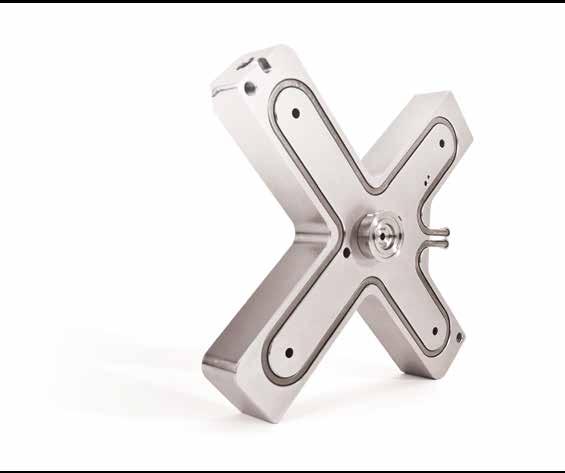
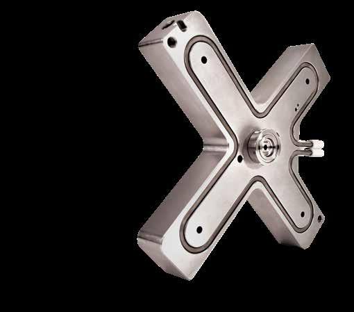
30 MX zzle MX zzle Overview MX nozzle, specifically designed for multi cavity manifold systems and hot halves. 1. MX FEATURES Mould design Efficiently designed profile to allow closer cavity pitching Shares the same gate profiles as BX and SX Available in both thermal and valve gate options Consistent nozzle lengths across the range Ability to mould large parts with smaller nozzles due to optimum flow characteristics Operation Wide moulding window Excellent temperature profile and thermal stability Operates at low moulding pressure and temperature Optimum cycle times due to superior thermal insulation Uses an advanced micro coil heater with integrated heat deflection tube Installation and maintenance Front loading capability for easier servicing of tips, heaters and thermocouples Simple machining and installation requirements Improved reliability due to the use of advanced materials Common tip and nut options provide ready availability of spare parts Dowel Pin Body Heater Sleeved 4 Tip 5 Thermocouple 6 Thermocouple Clip 7 8 Heater Cap Snap Ring 9 Nut 30
31 MX zzle MX zzle Series L (nozzle) 12.0 A/F = 24 Ø6.0 Ø28.0 L (nozzle) 12.0 A/F = 26 Ø7.0 Ø30.0 L (nozzle) 15.0 A/F = 36 Ø8.0 Ø40.0 Ø10.0 Ø22.9 Ø12.0 Ø24.9 Ø15.0 Ø31.5 MX13 MX16 MX19 MX Standard Lengths Series L (nozzle)* 13 Series Series Series * Custom lengths available on request, BX recommended 31
32 BX zzle BX zzle Overview BX nozzle is designed to provide cost sensitive solutions for low to medium cavitation applications, not requiring hot half construction. 1. BX FEATURES Mould Design Ability to easily order special length nozzles Shares the same gate profiles as MX and SX Available in both thermal and valve gate options Consistent nozzle lengths across the range Ability to mould large parts with smaller nozzles due to optimum flow characteristics 1 2 Dowel Pin Body Operation Wide moulding window Excellent temperature profile and thermal stability Operates at low moulding pressure and temperature Optimum cycle times due to superior thermal insulation Uses an economical and robust coil heater Installation and Maintenance Simple machining and installation requirements Improved reliability due to the use of advanced materials Common tip and nut options provide ready availability of spare parts 3 Heater 4 Heater Cover 5 Tip Thermocouple Thermocouple Clip Heater Cap Snap Ring Nut 32
33 BX zzle BX zzle Series Ø6.0 Ø7.0 Ø8.0 L (nozzle) L (nozzle) A/F = 31 A/F = 34 A/F = 36 Ø34.0 Ø38.0 Ø40.0 L (nozzle) 12.0 Ø10.0 Ø12.0 Ø15.0 Ø27.0 Ø30.0 Ø33.0 BX13 BX16 BX19 Ø12.0 L (nozzle) 20 A/F = 45 Ø50.0 BX Standard Lengths Series L (nozzle)* 13 Series Series Series Series * Custom lengths available on request Ø23.0 Ø43.0 BX27 33
34 SX zzle SX zzle Overview With two heaters the SX nozzle is perfectly suited for all single nozzle applications. 1. SX FEATURES 1 Circlip Mould Design Ability to easily order special length nozzles Shares the same gate profiles as MX and BX Consistent nozzle lengths across the range Ability to mould large parts with smaller nozzles due to optimum flow characteristics Operation Separate heater for the nozzle head for maximum temperature control Wide moulding window Excellent temperature profile and thermal stability Operates at low moulding pressure and temperature Optimum cycle times due to superior thermal insulation Uses economical and robust coil heaters Installation and Maintenance Simple machining and installation requirements Improved reliability due to the use of advanced materials Common tip and nut options provide ready availability of spare parts Sprue Heater Cover Sprue Heater Sprue Thermocouple Dowel Pin Body Heater 8 Heater Cover 9 10 Thermocouple Tip Thermocouple Clip Heater Cap Snap Ring Nut 34
35 SX zzle SX zzle Series 7 5 Ø32 Ø24 Ø3* Ø6 L (nozzle) 18 L (nozzle) A/F = 36 Ø40 A/F = 46 Ø50 Ø32 Ø24 Ø4* Ø7 Ø38 Ø30 Ø4* Ø8 L (nozzle) Ø10 Ø27 Ø12 Ø30 Ø15 Ø33 A/F = 46 Ø50 Ø38 Ø30 Ø5* Ø A/F=36 Ø40 SX13 SX16 SX19 SX Standard Lengths Series L (nozzle)** 13 Series Series Series Series * Open to suit machine nozzle size ** Custom lengths available on request L (nozzle) Ø23 Ø43 SX27 35
36 FlowLoc Range FlowLoc Range Overview FlowLoc Technology Range are designed to provide a secure, leak-proof solution for multi-cavity manifold systems. 1. FLOWLOC FEATURES Design Available in 16, 19 and 27 Series nozzle in a variety of lengths with the ability to order special length nozzles Features a threaded base to attach securely to the manifold Available in thermal gate Suitable for low to high cavity applications Shares the same gate profiles as existing X-Range nozzles Operation Incorporates advanced heating technology with embedded heaters for exceptional thermal performance Threaded nozzle screws directly into the manifold providing a secure, leak-proof solution Capable of processing a wide range of polymers including abrasive fillers Excellent thermal profile along the entire length of the nozzle ensures a wide moulding window Suitable for high pressure applications Installation and Maintenance Simple installation via threaded base Utilises Mastip s proven X-Range tips and nuts Individual components are readily available on express order from our service team Stainles Steel Body Heater Thermocouple 4 Thermocouple Clip 5 Heater Cap 6 Circlip 7 Tip 8 Nut 36
* 16 Series 75 95 115 130 145 175 19 Series 75 95 115 130 145 175 27 Series 75 95 115 130 145 175 225 275 * Lengths can be customised to suit your")
37 FlowLoc Range FlowLoc Range L (nozzle) Ø7.0 FlowLoc Standard Lengths Series L (nozzle)* 16 Series Series Series * Lengths can be customised to suit your requirements on request TX L (nozzle) L (nozzle) Ø12.0 Ø12.0 A/F = 27 L (nozzle) Ø8.0 A/F = 36 TX27075 TX27175 A/F = 30 TX19 A/F = 36 TX27225 TX

38 MJ zzle MJ zzle Overview MJ nozzle, specifically designed for close cavity pitching. 1. MJ FEATURES Mould design zzle pocket profile for improved cooling performance and gate strength Optimal flow characteristics for ease of moulding Close cavity pitching Operation Wide moulding window Excellent temperature profile and thermal stability Operates at low moulding pressure and temperature Short cycle times Installation and maintenance Simple installation Front loading for ease of servicing Improved reliability 1 2 Dowel Pin Body 3 Tip 4 Heater 5 Thermocouple 6 Snap Ring 38
39 Ø24.0 MJ zzle MJ zzle Series A/F = 20 Ø4.0 L (nozzle) 12.0 MJ Standard Lengths L (nozzle)* 09 Series Ø7.0 * Custom lengths available on request Ø14.0 MJ Gating Options ONT ONT +5 ONT L (nozzle)
40 VeriShot Single Valve Gate System VeriShot Single Valve Gate System Mastip s VeriShot is an extremely compact, adjustable single valve gate system. The VeriShot incorporates advanced heating technology for exceptional thermal performance in applications requiring high cosmetic finish, high flow rates and dimensional accuracy. 1. VERISHOT FEATURES Design Available to suit TX19 & TX27 series threaded nozzles Compact annular design Reduced mould height Multiple gate profiles to suit a broad range of applications VeriShot functions as a locating ring for mould alignment Locating ring supplied in metric and imperial sizes Cap Screw M6 (metric option) or ¼ UNC (inch option) Locating Ring Dowel Pin Ø6 x 20 Cap Screw M8 x 90 Striker Plate Dowel Pin Ø5 x 28 Upper Manifold Operation Advanced heating technology Exceptional thermal performance Capable of processing a wide range of polymers Adjustable valve pin Incorporates superior FlowLoc Technology providing a secure, leak-proof solution Valve Pin Adjustment Packers 9a 9b 9c 9d Pin Locking Screw Valve Pin Wear Strip Top O-Ring ID 79 x 3 Piston Installation and Maintenance Simple Installation Utilises proven X-Range tips and nuts Wear Strip Bottom Dowel Pin Ø6 x O-Ring ID 100 x 3 O-Ring ID 79 x 3 O-Ring ID 115 x 3 19 O-Ring ID 5 x Cylinder 21 Cap Screw M5 x 40 Button Cap Screw M4 x O-Ring ID 6 x VeriShot Heater 25 Dowel Pin Ø5 x Valve Pin Seal Lower Manifold Dowel Pin Ø3 x 12 Thermocouple FlowLoc zzle 40
41 VeriShot Single Valve Gate System VeriShot Single Valve Gate System Ø Ø Øxxx.xx* L (nozzle) Min FlowLoc (nozzle)** * Metric Inch 99.85mm 3.99 VeriShot zzle Compatibility Description FlowLoc zzle** Tip Supplied Pin Size L (nozzle) VeriShot X19 TX19 Ø OV / TV VeriShot X27 TX27 Ø * Lengths can be customised to suit your requirements on request 41
42 MVG25 Headed Pin Valve Gate System MVG25 Headed Pin Valve Gate System 1. MVG25 FEATURES Mould Design Available to suit MX and BX zzles Standard minimal pitching is 55mm can be modified to fit 43mm Backplates 50mm minimum Conical or Cylindrical shut off Easy machining of the pockets Pneumatic circuit integrated with the backplate Moulding Benefits Reduced moulding pressure Increased moulding window Lower mould filling stress results in better part quality Reduced gate cooling requirements 1 2a a Blanking Plate Screw Blanking Plate 2b Blanking Plate Seal Pin Locking Screw Pin Head Seal Valve Pin Adjustment Packer Installation and Maintenance Easy machining and installation Easy seal replacement Valve pin height is adjustable Comes with Headed Pin design, with incremental adjustment 7 Valve Pin 6b 6c 6d 8 Valve Pin Adjustment Packers Piston Main Seal Piston Piston Rod Seal Circlip Cylinder 13 Cylinder End Seal 14 Locating Spacer 15 Valve Pin Seal 42
43 MVG25 Headed Pin Valve Gate System MVG25 Headed Pin Valve Gate System MVG25 Blanking Plate Ø54.0 MVG25 Cylinder Assembly MVG25 Spacer 50.0 Min MVG25 Valve Pin 10.0 MVG25 zzle Compatibility Description zzle Tip zzle Length Supplied Pin Size MVG25-P1 Headed Pin MX13 / BX13 OV Ø2.0 MVG25-P1 Headed Pin MX16 / BX16 OV / TV Ø2.5 43
44 MVG40 Headed Pin Valve Gate System MVG40 Headed Pin Valve Gate System 1. MVG40 FEATURES Mould Design Available to suit MX and BX zzles Standard minimal pitching is 75mm - can be modified to fit 58mm pitching Backplates 55mm minimum Conical or Cylindrical shut off Easy machining of the pockets Pneumatic circuit integrated with the backplate Moulding Benefits Reduced moulding pressure Increased moulding window Lower mould filling stress results in better part quality Reduced gate cooling requirements Installation and Maintenance Easy machining and installation Easy seal replacement Valve pin height is adjustable Comes with Headed Pin design, with incremental adjustment 1 2a 3 4 5a 6 Blanking Plate Screw Blanking Plate 2b Blanking Plate Seal Pin Locking Screw Valve Pin Adjustment Packer Valve Pin 5b 5b 5b 7 Valve Pin Adjustment Packers Piston Main Seal Piston Piston Rod Seal Circlip 11 Cylinder 12 Cylinder End Seal 13 Locating Spacer 14 Valve Pin Seal 44
45 MVG40 Headed Pin Valve Gate System MVG40 Headed Pin Valve Gate System MVG40 Blanking Plate Ø75.0 MVG40 Cylinder Assembly 55.0 Min MVG40 Spacer MVG40 Valve Pin 10.0 MVG40 zzle Compatibility Description zzle Tip zzle Length Supplied Pin Size MVG40-P1 Headed Pin MX13 / BX13 OV Ø2.0 MVG40-P1 Headed Pin MX16 / BX16 OV / TV Ø2.5 MVG40-P1 Headed Pin MX19 / BX19 OV / TV Ø3.0 MVG40-P1 Headed Pin BX27 OV / TV Ø5.0 45

46 MVG40 Threaded Pin Valve Gate System MVG40 Threaded Pin Valve Gate System 1. MVG40 FEATURES Mould Design Available to suit MX and BX zzles Standard minimal pitching is 75mm - can be modified to fit 58mm pitching Backplates 55mm minimum Conical or Cylindrical shut off Easy machining of the pockets Pneumatic circuit integrated with the backplate Moulding Benefits Reduced moulding pressure Increased moulding window Lower mould filling stress results in better part quality Reduced gate cooling requirements Installation and Maintenance Easy machining and installation Easy pin adjustment and seal replacement while the mould remains assembled Comes with Threaded Pin design fully adjustable 1 2a Blanking Plate Screw Blanking Plate 2b Blanking Plate Seal Pin Locking Screw Valve Pin Piston Main Seal Piston 8 9 Piston Rod Seal Circlip 10 Cylinder 11 Cylinder End Seal 12 Locating Spacer 13 Valve Pin Seal 46
47 MVG40 Threaded Pin Valve Gate System MVG40 Threaded Pin Valve Gate System MVG40 Blanking Plate Ø75.0 MVG40 Cylinder Assembly MVG40 Spacer MVG40 Valve Pin Min MVG40 zzle Compatibility Description zzle Tip zzle Length Supplied Pin Size MVG40-P2 Threaded Pin MX13 / BX13 OV Ø2.0 MVG40-P2 Threaded Pin MX16 / BX16 OV / TV Ø2.5 MVG40-P2 Threaded Pin MX19 / BX19 OV / TV Ø3.0 MVG40-P2 Threaded Pin BX27 OV / TV Ø5.0 47
48 MVG55 Headed Pin Valve Gate System MVG55 Headed Pin Valve Gate System 1. MVG55 FEATURES Mould Design Available to suit BX zzle in 27 Series Standard minimal pitching is 95mm can be modified to fit 74mm Backplates 55mm minimum Easy machining of the pockets Pneumatic circuit integrated with the backplate Moulding Benefits Reduced moulding pressure Increased moulding window Lower mould filling stress results in better part quality Reduced gate cooling requirements Installation and Maintenance Easy machining and installation Easy seal replacement Valve pin height is adjustable Comes with Headed Pin, with incremental adjustment 1 2a 3 4 5a 6 Blanking Plate Screw Blanking Plate 2b Blanking Plate Seal Pin Locking Screw Valve Pin Adjustment Packer Valve Pin 5b 5c 5d 7 Valve Pin Adjustment Packers Piston Main Seal 8 Piston 9 10 Piston Rod Seal Circlip 11 Cylinder 12 Cylinder End Seal 13 Locating Spacer 14 Valve Pin Seal 48
49 MVG55 Headed Pin Valve Gate System MVG55 Headed Pin Valve Gate System MVG55 Blanking Plate Ø95.0 MVG55 Cylinder Assembly MVG55 Spacer 55.0 Min MVG55 Valve Pin 10.0 MVG55 zzle Compatibility Description zzle Tip zzle Length Supplied Pin Size MVG55-P1 Headed Pin BX27 OV / TV Ø5.0 49

50 MVCH Valve Gate System MVCH Valve Gate System 1. MVCH FEATURES Mould Design Available to suit MX 16, 19 and BX 16, 19 and 27 series Standard minimal pitching is 58mm Backplates 86mm minimum Easy machining of pockets Hydraulic actuation Moulding Benefits Improved part quality Reduced moulding pressure Increased moulding window Lower mould filling stress results in better part quality Reduced gate cooling requirements Installation and Maintenance Adjustable pin length Back Plate Screw Back Plate Cylinder Cylinder Screw 5 Lock Nut 6 Pin Holder 7 Pin 8 Pin Holder Cap 9 Steel Spacer 10 Insulation Spacer 11 Seal 50
51 MVCH Valve Gate System MVCH Valve Gate System 80x58 54x54 L (nozzle) MVCH MVCH2510 MVCH zzle Compatibility Description Stroke Tip Supplied Pin Size zzle L (nozzle) MVCH TV MVCH OV Ø2.5 MX16 / BX MVCH TV MVCH OV Ø3.0 MX19 / BX MVCH TV MVCH OV Ø5.0 BX

52 Manifold Configuration Manifold Components Exploded view of a Standard 2 Drop Hot Runner System 1 Spacer Assembly 2 Sprue Bush & Heater Thermocouple 3 4 Manifold Heater & Ceramic Connector 5 Manifold End Plug Assembly 6 7 Locator 9 zzle Orientation Dowel Pin 8 52
53 Selecting a Manifold Configuration Selecting a Manifold Configuration When deciding on a manifold layout it is important to consider the following: The number of injection points required per cavity The number of cavities in the mould Minimum distance between nozzles Balancing of the manifold Spacing of cavities to provide adequate room for cooling Gate and cavity Strength of the mould Sufficient steel between cavities Mould size versus machine platen size Total shot weight For multi-cavity moulds balancing is critical to achieve consistent dimensions, cosmetic appearance and processing conditions across cavities. It is therefore strongly recommended that for multi-cavity moulds a manifold layout providing natural balancing is used. Natural Balancing: In order to achieve natural balance, the material must flow through identical geometry from the machine nozzle to each of the gates. This means identical: Flow distance Runner diameters Number and angle of bends This ensures that every gate receives material in exactly the same condition. With natural balance, the balance is inherent in the design, and is not based on a specific material or processing temperature. Rheological balancing: Is a method of balancing by using different runner sizes to artificially provide identical pressure drop at each gate. To accurately predict this, the flow properties of the material must be known, along with the flow rate and anticipated processing temperature. Any variation from the processing conditions used during design will result in an unbalanced system. Some drop configurations can not be naturally balanced unless the drops are on a PCD and must therefore be rheologically balanced. E.g. 3, 5, 7, 9, 10, 11, 13, 14, 15, etc All standard Mastip manifolds (except 3 Drop 3x1) are naturally balanced. Best Configuration Equal and symmetrical drop positions Poor Configuration Unbalanced drop positions R1 L R2 L L L Refer to the Manifold Guidelines Section for standard drop configurations. L1 L2 53


54 Nexus Systems 1. Nexus Systems Mastip s Nexus Pre-Assembled and Pre-Wired hot runner systems are designed for fast, simple installation out of the box without requiring any further technical assembly. Nexus Systems incorporates superior FlowLoc technology providing a secure, leakproof solution. The FlowLoc range ensures an excellent thermal performance using the latest heating technology. NEXUS SYSTEMS Fully customised to suit your application requirements Able to process commodity and engineering grade polymers Fast, simple installation out of the box Advanced heating technology with embedded heaters FlowLoc nozzles connect securely to manifold via threaded base Stainless steel nozzles Proven performance of X-Range nozzle technology Customised trunking for wiring Advanced heating technology for superior thermal performance Leak-proof solution via screwed in nozzles Accidental cold starting will not result in polymer leakage User-friendly maintenance Excellent thermal profile ensures a wide moulding window Unit removes easily from mould facilitating quick, easy service and maintenance 54


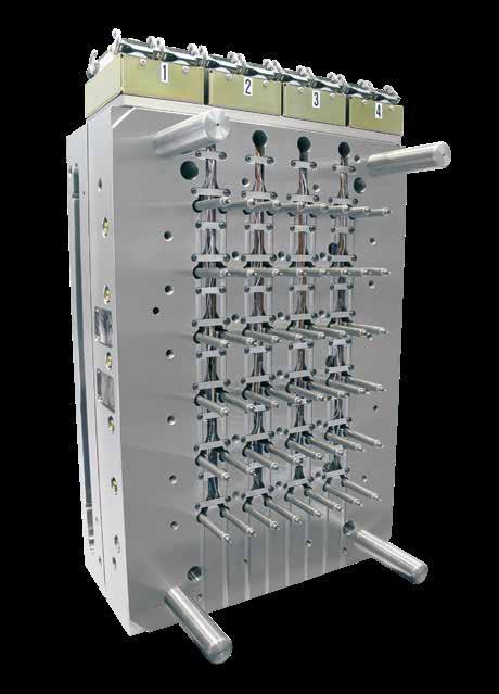
55 Hot Half System Hot Half System All Mastip s Hot Half solutions, from low to high cavity thermal or valve gate systems, are delivered as a complete solution to integrate seamlessly with your completed mould. 1. HOT HALF FEATURES Applications Fully customised to suit your application requirements Able to process commodity and engineering grade polymers Features Plates available in high quality P20 steel or 420 stainless steel Proven performance of X-Range nozzle technology Delivered fully assembled and fully wired Benefits Advanced heating technology for superior thermal performance Easy servicing of nozzles, tips, thermocouples and heaters Heaters are front loading Excellent thermal profile ensures a wide moulding window 3-year leak proof guarantee 55
56 Additional Considerations Additional Considerations To select a Hot Runner System to match your part and material specifications consideration must be given to the following: Gate type Gate size zzle range and series zzle tip style zzle nut type Selecting Material There are three broad categories of materials each relating to its moulding characteristics: Easy Medium Difficult When selecting material consider the following: Materials with large percentages of filler (for example, >15%) or very low MFI, the material classification moves up a grade (for example, easy to medium). Selecting a Gate Type The following factors must be considered when selecting a gate type: Shot size of part Material to be moulded Material Viscosity Additives Glass fibre Flame retardant Gate surface finish Thickness of part walls Longest flow length of part Required cycle time When designing an injection mould, the type, size and location of the gate is one of the most important consideration for correct moulding of the part. Incorrect gate position can result in uneven filling, over packing, and dimensional instability. Available gate types include: Direct gating Valve gating Direct gating is the most common gate type as it offers simple construction and reliability. Refer to the zzle Section for more information about Gate Types 56
57 Additional Considerations Gate Size The correct gate size ensures a good thermal gate is achieved and minimises the pressure drop across the gate while maintaining its structural integrity. Parts with very thin wall sections or very long flow lengths need a larger nozzle and gate to achieve proper filling, this may require increasing the nozzle by one to two series. The gate sizes effects the: Flow rate Pressure drop through the system Cycle time Thermal gate shut off after filling Cosmetic impact of the gate on the part Cooling in the gate area The gate size is dependent on the: Material Material viscosity Part wall thickness Gate cooling* * Gate cooling is a complex variable and consideration must also be given to cycle time, gate profile, and land length. Gate Size Variables gate size vs material gate size vs MFI gate size vs part wall thickness gate size vs gate cooling small gate large gate large gate large gate large gate amorphous material crystalline material small gate low MFI material high MFI material small gate thin part wall thick part wall small gate cold gate cooling hot gate cooling 57
58 System Selection - Example Working Example of a System Selection To calculate the number and size of nozzles required to fill a part an initial estimate of the number of nozzles or injection points must be made. A good starting point is to limit the flow length / part thickness (L/t) ratio to the typical values for that type of material. Refer table on page 12 - Typical Flow Length Ratios. 1 Part Details 3 Hot Runner System Initial Estimates Description Fluorescent Light Base Number of zzles (N) 4 Overall Size 700 x 150 x 40 mm L/t 87.5 with 4 zzles Wall thickness (t) 1.5mm Part Volume (V) 220ml 2 Type Flame retardant Material ABS Grade Cycolac T-XS Specific Gravity (SG) 1.3 L/t for wall thickness 96 Material Category Medium - due to flame retardant move up one grade to difficult. 4 Hot Runner System Analysis Results Injection Pressure 93.65MPa Injection Time (T) 1.36 Total Flow Rate (F) (V*SG)/T=(220*1.3)/1.36=210g/s Flow Rate per zzle (F/N)=210/4=52.5g/s Part Model - Fluorescent Light Base zzle Series Selection 19 Series zzle is best suited due to the required flow rate of 52.5 g/sec. and the ABS material fitting the medium to difficult material category. 58

59 Temperature Control System MMA15 Modular Temperature Controller 1. MMA15 FEATURES Benefits Soft Start function to protect heaters during startup Idle mode after power failure, to protect module and Hot Runner System Open Thermocouple and reversed Thermocouple detection Self test on startup Single Zone Temperature Controller (MSA) Uses standard MMA15 modules Supplied with 3m cable and mould end connectors 10A rating Multi Zone Temperature Controller (MMA) Standard MMA cabinet configurations are 1 to 12 zones Supplied with 3m cables and mould end connectors 15A rating on all zones Technical Specifications Mains input power Output current capability Thermocouple User interface: output Temperature control range Temperature control accuracy Thermocouple open detect Thermocouple reversed detect Start up self test Standby Mode Auto tune 240Vac / Hz MMA=15A MSA=10A J and K type, selectable by DIP switch SV and PV LED 0ºC to 537ºC (32ºF to 999ºF) ±1ºC, selectable by DIP switch Once or every time (user selectable) 59

60 Sequential Control System G-Series GV24 Modular Sequential Control System 1. GV24 FEATURES Benefits Regulation of the injection quantity from each individual gate Quality of the moulded part can be improved by removing or repositioning of weld lines Injection is performed with minimum clamping force due to the gates not all opening simultaneously Optimum control over part fill Standard GV24 cabinet configurations are 2 to 8 zones Supplied with 3m cable and mould end connectors Mains input power Injection signal input power supply Solenoid valve voltage Technical Specifications Single phase AC V (50/60 Hz) 24VDC, 110VAC, 220VAC 24VDC, 110VAC, 220VAC Operating temperature range -10 ºC to 50 ºC Operating modes Timer Increment Timer Range Automatic input voltage Manual override Three modes (Continuous Sequence, Intermittent Sequence and Delay Sequence) 0.1 seconds seconds 60

 24VDC, 220VAC Signal voltage, 100mA/Zone Operating temperature range -10 ºC")
61 Sequential Control System G-Series GTV8 Integrated Sequential Controller 1. GTV8 FEATURES Regulation of the injection quantity from each individual gate Quality of the moulded part can be improved by removing or repositioning of weld lines Injection is performed with minimum clamping force due to the gates not all opening simultaneously Optimum control over part fill Pneumatic only Standard GTV8 cabinet configurations are 8 zones compact design Mains input power Injection signal input power supply Solenoid output power supply Technical Specifications Single phase AC 220V (50/60 Hz) 24VDC, 220VAC Signal voltage, 100mA/Zone Operating temperature range -10 ºC to 50 ºC Operating modes Timer Increment Timer Range Automatic input voltage Manual override Two modes (Continuous Sequence and Intermittent Sequence) 0.1 seconds seconds 61
62 tes tes 62
63
64 Mastip Head Office New Zealand Physical Address 558 Rosebank Road, Avondale Auckland 1026, New Zealand Postal Address PO Box 90651, Victoria St West Auckland 1142, New Zealand Phone: mastip@mastip.com Mastip Regional Office Europe Phone: europe@mastip.com Mastip Regional Office rth America Phone: northamerica@mastip.com Mastip Regional Office China china@mastip.com For a full list of Distributors, please visit Copyright Mastip Technology Limited. Information subject to alteration V3.09
Hot Runner Solutions for Technical Moulding. An Introduction to Mastip Technology.
 Hot Runner Solutions for Technical Moulding An Introduction to Mastip Technology www.mastip.com Company Profile Mastip is a leading supplier of innovative hot runner solutions to the global plastic injection
MVG25 Valve Gate.
 www.mastip.com Assembly Overview System Overview Assembly Overview 1. IMPORTANT!! The back plate must be cooled and must not exceed 100 C. The cylinder should be in the closed position at all times except
Nexus Pre-Wired Hot Runner System
 Nexus Pre-Wired Hot Runner System www.mastip.com Overview Assembly Overview L Key Features Fast and simple installation out of the box Incorporates advanced heating technology for superior thermal performance
MVG40 Threaded Pin Valve Gate
 MVG40 Threaded Pin Valve Gate www.mastip.com Assembly Overview System Overview Assembly Overview 1. IMPORTANT!! The back plate must be cooled and must not exceed 140 C. The cylinder should be in the closed
smart hot runner solutions
 Mould Design Recommendations for Hot Runner Applications smart hot runner solutions www.mastip.com Contents Mould Design Recommendations pg 3 4 5 6 6 6 8 9 11 12 13 Contents Introduction 1.0 Plate Requirements
Hot Runner Guide Layout and Design
 H O T R U N N E R Layout and Design Stabilize your Process CAT-14-0001_EN-Rev05 EN 11/2017 T E C H N O L O G Y Layout and Design The purpose of this The - Layout and Design is intended to help everyone
Hot Runners and Temperature Controllers
 Hot Runners and Temperature Controllers Better parts, faster cycles Benefits Complete tooling solutions Application specific solutions Pristine gate quality Fastest cycles Fast color change Accurate, reliable
Mold Design. 7. Mold Design Runner & Gate. Bong-Kee Lee School of Mechanical Engineering Chonnam National University
 7. Runner & Gate Bong-Kee Lee Chonnam National University Delivery System Delivery System (Feed System) sprue (for a cold runner mold) cold slug well (for a cold runner mold) runner gate basic feed system
Hot Sprue Bushings Products/Technical Guide
 Hot Sprue Bushings Products/Technical Guide USB8 And SB8 Hot Sprue Bushings Notes 1. Cold bushing length must allow for thermal expansion to fit specified mold length. 2. For special "A" length order next
auxiliary technologies advanced molding applications technical services overview Accu-Valve for optimum part quality
 overview Recognized as the hot runner technology leader for over 4 decades, Mold-Masters has developed the widest range of system solutions that go beyond the usual day to day requirements. Our MasterSOLUTION
Promix Solutions trust the leader. Static Mixers Solutions for Injection Molding
 Promix Solutions trust the leader Static Mixers Solutions for Injection Molding Your partner in the plastics processing industry Founded in 2012 as a spin-off of Sulzer Chemtech Subsidiaries in Winterthur,
D-M-E Hot Runner Systems
 D-M-E Hot Runner Systems The best solution for precision thermoplastic micromolding Engineered for the challenges of tight pitch molding The D-M-E Stellar Hot Runner System brings high performance, exacting
Feed System Design OBJECTIVES IN FEED SYSTEM DESIGN DPT 321 INJECTION MOLD DESIGN COURSE CONTENT & COURSE OUTCOMES. Introduction of Feed System
 COURSE CONTENT & COURSE OUTCOMES School of Manufacturing Engineering COURSE CONTENT Chapter 5: Gate, Runner and Venting Design DESCRIBE and EXPLAIN the type of gates, and gate selection. DESCRIBE and EXPLAIN
Classic & Threaded Nozzle Selection Guide...J4. Emerald Ceramic Technology...J8. Emerald Classic Nozzle...J6. Emerald Hot Runner Systems...
 J1 Classic & Threaded Nozzle Selection Guide...J4 Emerald Ceramic Technology...J8 Emerald Classic Nozzle...J6 Emerald Hot Runner Systems...J3 Emerald Threaded Nozzle...J7 Policosmetic Hot Runner Systems...J9
Gated and assembled in one moulding cycle
 Customer information from EWIKON Heißkanalsysteme GmbH Gated and assembled in one moulding cycle Tailored hot runner solution for a demanding -component mould concept Pages - 5 Processing of sensitive
Machine nozzle with needle shut-off type HP pneumatically or hydraulically controlled
 Machine nozzle with needle shut-off type HP pneumatically or hydraulically controlled Applications: Thermoplastics (not applicable for PVC) Shut-off mechanism: Needle shut-off with integrated 2-way actuator
Machine nozzle with needle shut-off type HP pneumatically or hydraulically controlled. Needle shut-off
 Machine nozzle with needle shut-off type HP pneumatically or hydraulically controlled Needle shut-off Applications: Thermoplastics (not applicable for PVC) Shut-off mechanism: Needle shut-off with integrated
Order from MARYLAND METRICS P.O. Box 261 Owings Mills, MD USA web:
 Push-In Fittings LF 3000 LF 3200: 3 mm LIQUIfit LF 300 LF 300/ LF 3900 LF 0 PARKER LEGRIS Industrial Connector Systems Products are available from: MARYLAND METRICS P.O. Box 21 Owings Mills, MD 21117 USA
Customer information from EWIKON Heißkanalsysteme GmbH. Doubled output. New stack mould concept for the production of syringe plungers
 Customer information from EWIKON Heißkanalsysteme GmbH Doubled output New stack mould concept for the production of syringe plungers Pages 2-4 Enhanced operational safety More performance for small machines
FlowControl. Smart & Effective. Stabilize your Process
 FlowControl Smart & Effective Stabilize your Process FlowControl Demanding visual appearance with precise dimensional stability Gloss level, evenly textured surfaces, color uniformity and aesthetics, are
CATALOG. Actuated Diaphragm Valve DN PVC-U / PVC-C / PP-H / PVDF / ABS SMART IN FLOW CONTROL.
 CATALOG Actuated Diaphragm Valve DN 15-100 PVC-U / PVC-C / PP-H / PVDF / ABS SMART IN FLOW CONTROL. TABLE OF CONTENTS Type 186 - DN 12-15 (MA 10) 04 General information - Technical specification 04 Sectional
Self Contained Dual Shaft Body Less Valve Gate Nozzle System, Single Application
 DSB-500 Self Contained Dual Shaft Body Less Valve Gate Nozzle System, Single Application NOZZLE DESCRIPTION: The "DSB-500 Nozzle Assembly is furnished with a heated radius cap and locating ring (Ø3.990)
PNEUMATICALLY ACTUATED 2-WAY
 482 DN 25-65 The 482 diaphragm valve is particularly suitable for shutting off and regulating abrasive or dirty fluids. The new internal geometry of the body optimises fluid dynamic efficiency by increasing
Mold-Masters Europe. by Robert Kirkby MasterCARE-Team, EMEA ( )
") Mold-Masters Europe 1 by Robert Kirkby MasterCARE-Team, EMEA (2012-05-11) Master-Series I The Flagship 12 standard gate options 6 standard nozzle sizes Precise temperature control with brazed heater technology
Mold-Masters Europe 1 by Robert Kirkby MasterCARE-Team, EMEA (2012-05-11) Master-Series I The Flagship 12 standard gate options 6 standard nozzle sizes Precise temperature control with brazed heater technology
INJECTION MOULDING TROUBLESHOOTING GUIDE
 Page : 1 / 12 BLACK SPECKS OR STREAKS Excessive residence time in the barrel Hang-up of Molten material in the injection barrel or runner system Contamination of the injection barrel Degradation due to
ALLROUNDER 275 V. Vertical free-space system Clamping force: 28 tons Injection unit: 1.4 oz, 2.3 oz
 ALLROUNDER 275 V Vertical free-space system Clamping force: 28 tons Injection unit: 1.4 oz, 2.3 oz MACHINE DIMENSIONS 275 V 35.43 2.18 70.1 113.39 1) 119.1 2) 111.81 1) 115.95 2).57 75.1 31.5 35.43 min.35.43
MAGNA T SERVO. 500 to 5,500 kn
 MAGNA T SERVO 500 to 5,500 kn A NEW STANDARD IN TOGGLE TECHNOLOGY Energy Efficient, Rugged & Reliable, Precise & Consistent, Versatile & User Friendly MAGNA T SERVO TOGGLE INJECTION MOLDING MACHINE Durable
485 - NC NO/DA DN
 485 - NC 285 - NO/DA DN 25-100 The 485/285 diaphragm valve is particularly suitable for shutting off and regulating abrasive or dirty fluids. The new internal geometry of the body optimises fluid dynamic
MacroPower MC t The flexible large-molding machine. world of innovation
 400 2000 t The flexible large-molding machine world of innovation MacroPower MULTI-COMPONENT SERIES Extra functionality and more freedom for design COMBIMOULD is the multi-component technology from WITTMANN
YUDO SINGLE VALVE NOZZLE SERIES III V E R. N O M N S V E N O
 SINGLE VALVE III Instruction Manual YUDO SINGLE VALVE NOZZLE SERIES III V E R. N O. 0 2 0 9 M N S V E N O Greetings Thank you for using YUDO Single Valve III System. YUDO fabricated Single Valve III System
Electric. Efficient. Compact & precise. ENGEL e-mac
 Electric. Efficient. Compact & precise. be the first. All-electric. Best-in-class efficiency and precision to the max. All of the s movements are performed by servo-electric drives. The all-electric drive
SERIES H-200 HOT MELT GUNS. Durable, high-speed automatic hot melt guns provide extensive pattern flexibility.
 SERIES H-200 HOT MELT GUNS Durable, high-speed automatic hot melt guns provide extensive pattern flexibility. Innovative gun designs allow more flexibility and control of bead size, shape and placement.
Machine bolt shut-off nozzle type BHP pneumatically or hydraulically controlled
 Machine bolt shut-off nozzle type BHP pneumatically or hydraulically controlled Applications: Thermoplastics (not applicable for PVC) Shut-off mechanism: Bolt shut-off with integrated 2-way actuator pneumatically
ENPLA. Any question? Access to Premium nozzle series WINA ENPLA. Headquarters Plant Subsidiary Sales office Agency
 www.yudo.com Any question? Access to http://qna.yudo.com Netherlands UK France Portugal Germany Italy Spain Czech Egypt Finland Poland Slovakia Russia Romania Weihai Turkey Iran Qingdao Syria China Korea
Vacuum pump system type
 type VS*P Vacuum component C O N T E N T S Series variation 166 20 mm width universal type (/M) 168 10.5 mm width universal type (/M) 184 31.5 mm width discrete type (VSQP) 214 11 mm pitch manifold dedicated
Function Fittings. Flow Control Regulators. Piloted Function Fittings. Non-Return Valves. LIQUIfit Pressure Fittings. Other Function Fittings
 Flow Control Regulators Piloted Non-Return Valves LIQUIfit Pressure Fittings Other Silencers Flow Control Regulators (P. 4-6) Blocking Fittings (P. 4-36) Piloted Non-Return Valves (P. 4-38) Function:
Selective Laser Sintering Printers. Production thermoplastic parts with ProX and spro SLS printers
 Selective Laser Sintering Printers Production thermoplastic parts with ProX and spro SLS printers Limitless Possibilities with Tool-less Manufacturing ELIMINATE THE TIME AND EXPENSE OF TOOLING Direct 3D
Power distribution components
 Industrial electronics Power distribution components Reliable, cost-effective, complete R England sv_001.fm Rittal power distribution components Bar centre distance (mm) Number of poles Busbar dimensions
Bergen liquid fuel engines Sustainable and affordable power systems
 Bergen liquid fuel engines Sustainable and affordable power systems B32:40 powerful and reliable Rolls-Royce has supplied liquid fuel oil-burning engines for power generation and mechanical drive applications
Pneumatic actuator. Inspired By Challenge
 Inspired By Challenge Actuation COMPACT actuator ESD system Interfaces Ordering code system Introduction Proven advantage The COMPACT actuator is a quarter-turn rack & pinion pneumatic actuator that doubles
Haitian Saturn Series
 PLASTICS MACHINERY Haitian Saturn Series HT 07001_GB Haitian International Co., Ltd Unit 1105 Metroplaza tower 2, 223 Hing Fong Road Kwai Fong N. T haitian@mail.haitian.com Haitian Partner: NINGBO HAITIAN
Page ATALOGUE. Web: Tel: Fax:
 Page ACUUM PARE ANKER ARTS ATALOGUE Page 2 CONTENTS PAGE GAUGES 3 SAUNDERS M TYPE VALVES 4 LEVER BALL VALVES 5 GATE VALVES 6 AIR ACTUATED VALVES 7 KNIFE GATE VALVES 8 ACRYLIC SIGHT TUBE 9 RUBBER SUCTION
Scientific COMBI 26 mm Twin Screw
 Scientific COMBI 26 mm Twin Screw Extruder type LTECC26-40 with Co and Counter-rotating twin screws for compounding of PVC and most other thermoplastic resins 26 mm COMBI twin screw with 15 KW drive and
Pelletising Systems. Moulding & Recycling Underwater pelletising systems for up to 15,000kg/hr. Strand pelletisers
 Pelletising Systems 0 Underwater pelletising systems for up to 5,000kg/hr Our modular pelletising systems are highly cost efficient & cover a wide range of applications: Primary pelletising Masterbatch
Facts and figures ALLROUNDER 1500 T
 Facts and figures ALLROUNDER 15 T Table diameter: 59.6 (15 mm) Clamping force: 176, 22, 275, 35 tons : 3.7 oz, 6.1 oz, 8.2 oz, 15.3 oz, 29.1 oz, 45.4 oz www.arburg.com 15 T Machine dimensions up to 22
BUILT SMART, CLEANS TOUGH!
 BUILT SMART, CLEANS TOUGH! BUILT SMART, CLEANS TOUGH! We understand that our customers have their unique cleaning challenges. SoAX Cleaning Systems is a line of pressure washers and self-serve equipment
Features of YUEN. Application
 YUEN TECHNICAL DATA Features of YUEN YUEN system is the smallest nozzle that YUDO supplies. This nozzle provides the most delicate product quality. We have many kinds of gate shapes to apply the nozzles
Brass Compression Fitting Range
 Compression Fitting Range Fittings Stud Fittings 0105 BSPT Page 5-9 0105 NPT Page 5-9 0101 BSPP/Metric Page 5-10 0101..39 BSPP Page 5-10 0101 Metric Page 5-11 01 BSPP Page 5-11 0109 BSPT Page 5-12 0109
Any question? Access to
 )NQDCN PGVYQTM www.yudo.com ny question? ccess to http://qna.yudo.com Czech Germany Finland Netherlands Russia Poland Slovakia Romania Turkey Iran Syria Israel UK France Italy Portugal Premium nozzle series
Facts and figures ALLROUNDER 375 V. Vertical free-space system Clamping force: 500 kn Injection unit (acc. to EUROMAP): 100, 170, 290.
: 100, 170, 290.") Facts and figures ALLROUNDER 375 V Vertical free-space system Clamping force: 500 kn Injection unit (acc. to EUROMAP): 100, 1, 290 www.arburg.com 375 V Installation dimensions Vertical version 1050 850
Facts and figures ALLROUNDER 375 V Vertical free-space system Clamping force: 500 kn Injection unit (acc. to EUROMAP): 100, 1, 290 www.arburg.com 375 V Installation dimensions Vertical version 1050 850
Spritzgiessautomaten. Innovative into the future. Data and Equipment
 Spritzgiessautomaten Innovative into the future Data and Equipment Compact range BOY has become the specialist in the manufacturing of injection moulding machines with clamping forces up to 1,000 kn. BOY
SECTION B1: MACHINE COMPONENTS
 SECTION B1: MACHINE COMPONENTS The machine portion of the Injected Metal Assembly system provides the means for: holding, heating and injecting the alloy; distributing and controlling electrical, pneumatic,
e-mac Electric. Efficient. Compact & precise.
 e-mac Electric. Efficient. Compact & precise. All-electric. Best-in-class efficiency and precision to the max. All of the ENGEL e-mac s movements are performed by servo-electric drives. The all-electric
Customer information from EWIKON Heißkanalsysteme GmbH. Enhanced efficiency. Diving mask frame production with a side gating hotrunner mould Pages 2-4
 Customer information from EWIKON Heißkanalsysteme GmbH Enhanced efficiency Diving mask frame production with a side gating hotrunner mould Pages 2-4 Gate exchange insert HPS III-MH valve gate technology
SECTION B: SYSTEM OPERATING COMPONENTS
 SECTION B: SYSTEM OPERATING COMPONENTS A brief description of the machine, Cable Processor Module and tooling will provide a better understanding of the various functions of the IMA system. SECTION B1:
NEW PRODUCTS MOULD MAKING I / 2018
 NEW PRODUCTS MOULD MAKING I / 2018 E 7048 BUILD-IN CYLINDER WITH FLANGE With the build-in cylinder the smallest installation spaces can be realised. The installation is very easy with the four screws supplied.
Bergen liquid fuel engines Sustainable and affordable power systems
 Bergen liquid fuel engines Sustainable and affordable power systems B32:40 powerful and reliable Rolls-Royce has supplied liquid fuel oil-burning engines for power generation and mechanical drive applications
Facts and figures ALLROUNDER 275 V. Vertical free-space system Clamping force: 250 kn Injection unit (according to EUROMAP): 70, 100.
: 70, 100.") Facts and figures ALLROUNDER 275 V Vertical free-space system Clamping force: 250 kn Injection unit (according to EUROMAP):, 100 www.arburg.com 275 V Installation dimensions 900 665 1782 2880 1) 3025 2)
Facts and figures ALLROUNDER 275 V Vertical free-space system Clamping force: 250 kn Injection unit (according to EUROMAP):, 100 www.arburg.com 275 V Installation dimensions 900 665 1782 2880 1) 3025 2)
Accessories. 9 Accessories
 Accessories 9 Accessories 9 ACCESSORIES 9 Accessories Page Pressure pad 20 Spacer 20 Retaining clip 20 Spacer disks 30 Titanium ring for nozzle head 30 Pry bar 30 Insulating caps 40 Socket spanners for
Haitian Partner: HAITIAN INTERNATIONAL HOLDINGS LIMITED Unit 1105 Level 11 Metroplaza Tower Hing Fong RD Kwai Fong N.T
 HAITIAN INTERNATIONAL HOLDINGS LIMITED Unit 1105 Level 11 Metroplaza Tower 2 223 Hing Fong RD Kwai Fong N.T haitian@mail.haitian.com www.haitian.com Haitian Partner: HT 20100805-EV NINGBO HAITIAN HUAYUAN
This is trial version
 Z-Standards Contents (Alphabetical order, terms partly according to DIN 16750) A All dimensions shown in this catalogue are specified in mm, given tolerances refer to an ambient temperature of 20 C Prod.-No.
Hot Runner System Instruction Manual
 Hot Runner System Instruction Manual Rev1.4 11 / 2011 RK Introduction Dear Customers, Thank you for purchasing a Synventive Hot Runner System. Our objective is to provide you with a product that is a good
TIMO. Any question? Access to Premium nozzle series WINA TIMO. Headquarters Plant Subsidiary Sales office Agency
 www.yudo.com ny question? ccess to http://qna.yudo.com Netherlands UK France Portugal ermany Italy Spain Czech Egypt Finland Poland Slovakia Russia Romania Weihai Turkey Iran Qingdao Syria China Korea
Transmitters: Relay Valve
 Relay Valve VR5/5 Series Appropriate output sequences are affected according to the signal received from the mechanical valve. It is equivalent to the auxiliary relay of an electrical system. Specifications
Compression Fittings. Brass Compression Fittings. Stainless Steel Compression Fittings. PL Nickel-Plated Brass Spigot Fittings
 Compression Fittings Compression Fittings Stainless Steel Compression Fittings PL Nickel-Plated Spigot Fittings Compression Fittings Compression Fittings Compression Fittings (P. 5-5) Stainless Steel Compression
Low Flow Air Atomizing
 XA Low Flow Air Atomizing TO DER: specify pipe size, body style, spray set-up #, 76 The XA nozzle system uses the energy in compressed air to produce highly atomized sprays at low flow rates. There are
The ROBUST Performer
 80 to 910 Ton The ROBUST Performer Energy Efficient Generous Specifications Robust & Reliable User Friendly Control The ROBUST Performer 3 Large Ram Diameter Provides Uniform Force Distribution across
PROCESS & AUTOMATED VALVES
 Process & utomated Valves HYDC s line of Process and utomated Valves complements our isolation valve knowhow and ability to supply high quality solutions to your valve requirements. 3-1 HV Series Inline
PERFORMANCE AND SPECIFICATION. BORING DIAMETER RANGE 1.5 to 24 BORING BAR STROKE 305, 610 or 915mm 12, 24, or 36
 MLB610 Line Boring Machine Rev 1.0 Page 1 of 9 DESCRIPTION A versatile and modular line boring machine offering a choice of electric, hydraulic and pneumatic boring bar drive motors, with a mechanical
The cold runner that matches your silicone.
 The cold runner that matches your silicone. Industry-specific solutions for Automotive I Consumer I Electrical I Medical I Packaging GÜNTHER Heisskanaltechnik Passion for (Cold Runner) Technology Liquid
Mixing Heads. High & Low Pressure Technology. General Purposes. Multi-Component & Dual-Hardness Applications. Filled & Reinforced Formulations
 Mixing Heads High & Low Pressure Technology General Purposes Multi-Component & Dual-Hardness Applications Filled & Reinforced Formulations Micro Shots & High Outputs Spray & Cavity Filling Pipe Insulation
Marking Systems. Paint Spray Systems Marking Blocks Paints & Inks
 Marking Systems Paint Spray Systems Marking Blocks Paints & Inks Various Applications Usage and Setup Flexibility Precise edging and maximum reproducibility with virtually zero overspray. Automated Dot
Band Heaters Maxiband Heaters Maxiband The Most Sought After Band Heater
 Band Heaters Maxiband Heaters Maxiband The Most Sought After Band Heater A B C D E F General purpose terminal box offers excellent protection to the exposed terminals. To simplify electrical wiring, the
Actuators & Surface Safety Valves
 Global Energy Market Solutions HYDRAULIC / PNEUMATIC Actuators & Surface Safety Valves Including: Accessories & Alternative Configurations 2017 Omni Valve Company, LLC, BRO-ACT Rev: 1.2 ENGINEERED FOR
DT04 08P + W8P
 Deutsch Connector Assortment Flip Kit *763354 This assortment contains 574 pieces/sets of widely used Deutsch Connectors. Flip Kits are handy both in the shop and the service vehicle. They are portable,
PC-Series Precision Linear Actuators. Optimize Your Machine and Save Energy With Reliable, High Performance, Compact Actuators
 PC-Series Precision Linear Actuators Optimize Your Machine and Save Energy With Reliable, High Performance, Compact Actuators Make the Change to Electric Enjoy superior performance and save time and energy
Movotec Drives > Folding Hand Cranks (small and large)
") Movotec Drives > Folding Hand Cranks (small and large) Can be mounted right-at-hand, yet folds completely out of the way when not in use. The small crank has a 100 mm radius and is intended for lifting
Movotec Drives > Folding Hand Cranks (small and large) Can be mounted right-at-hand, yet folds completely out of the way when not in use. The small crank has a 100 mm radius and is intended for lifting
Valve Gate Hot Runner Systems
 Otto Männer GmbH Unter Gereuth 9 11 79353 Bahlingen Germany Phone +49 (0) 7663 609-0 Fax +49 (0) 7663 609-299 info@maenner-group.com 10/17 Technical specifications subject to change. Valve Gate Hot Runner
ALLROUNDER 470 E. Distance between tie bars: 18.5 x 18.5 (470 x 470 mm) Clamping force: 110 tons Injection unit: 3.7 oz, 6.1 oz, 8.
 Clamping force: 110 tons Injection unit: 3.7 oz, 6.1 oz, 8.") ALLROUNDER 470 E Distance between tie bars: 18.5 x 18.5 (470 x 470 mm) Clamping force: 110 tons Injection unit: 3.7 oz, 6.1 oz, 8.2 oz MACHINE DIMENSIONS 470 E 51.24 33.44 max.16.34 4.72 80.71 83.62 15.75
ALLROUNDER 470 E Distance between tie bars: 18.5 x 18.5 (470 x 470 mm) Clamping force: 110 tons Injection unit: 3.7 oz, 6.1 oz, 8.2 oz MACHINE DIMENSIONS 470 E 51.24 33.44 max.16.34 4.72 80.71 83.62 15.75
Module. Section 9. NOTE: This section applies to applicators with CC200 modules B Issued 6/01. Manual 42-CF200-CM-01
 Section 9 NOTE: This section applies to applicators with CC200 modules. 9-0 Table of Contents i Table of Contents Section 9 1. Introduction............................................... 9-1 2. Specifications.............................................
Company Profile. Molding Tomorrow`s Technology & Service Today
 Company Profile Molding Tomorrow`s Technology & Service Today Our Mission: We are Committed to Providing Our Customers with Ground-Breaking Technical Innovations and Service that deliver the highest standards
DTP Series : Contacts (Open Barrel) Type Barrel Type GA Size
 Type Barrel Type GA Size") Deutsch Connectors DTP Series Deutsch s DTP Series connectors are the solution for your power application requirements. Building on both the DT and DTM design strengths, the DTP connector line was developed
Deutsch Connectors DTP Series Deutsch s DTP Series connectors are the solution for your power application requirements. Building on both the DT and DTM design strengths, the DTP connector line was developed
SECTION A: INTRODUCTION
 SECTION A: INTRODUCTION Overview of the Injected Metal Assembly (IMA ) process Fishertech s Injected Metal Assembly process combines assembly techniques with specialized die casting technology to increase
METAL STAMPING & FORMING EQUIPMENT. Straight Side. Mechanical Presses tons
 METAL STAMPING & FORMING EQUIPMENT Straight Side Mechanical Presses S2 165. 220. 330. 440. 660. 880-3300 tons S2 SERIES Straight Side Mechanical Presses Durable Reliable Versatile STRAIGHT SIDE MECHANICAL
The multi-function machine
 The multi-function machine Technical Description Multi Clamping unit asic hydraulic 500 kn 800 kn 1100 kn 18,5 kw 22 kw 30 kw Injection unit/ Distance Screw between tie bars V V V 370 x 370 120 200 22/25/30
GFX HEPCO GUIDANCE SYSTEM FOR BECKHOFF XTS
 PRT2 HEPCO GUIDANCE SYSTEM FOR BECKHOFF XTS hepcomotion.com HepcoMotion.com Contents Hepco Guidance Systems for Beckhoff XTS Introduction... 1 1-Trak and 1-Trak Lite System Composition... 2 PRT2 System
OAKLEAF INVESTMENT HOLDINGS 52 (Pty) ltd
 ltd") REV. 04 04 14 OAKLEAF INVESTMENT HOLDINGS 52 (Pty) ltd is by contract the exclusive import agent and service provider in South Africa for various foreign specialist manufacturers of FIELD PROCESS MEASURING
REV. 04 04 14 OAKLEAF INVESTMENT HOLDINGS 52 (Pty) ltd is by contract the exclusive import agent and service provider in South Africa for various foreign specialist manufacturers of FIELD PROCESS MEASURING
Machine shut-off nozzle for Elastomer; Type-E Integrated actuator and tempering system
 Machine shut-off nozzle for Elastomer; Type-E Integrated actuator and tempering system Application: Elastomeric plastics Shut-off technique: Integrated two way pneumatic actuator Characteristics: Integrated
ALLROUNDER 470 A. Distance between tie bars: 470 x 470 mm Clamping force: 1000 kn Injection unit (acc. to EUROMAP): 170, 290, 400
: 170, 290, 400") ALLROUNDER 470 A Distance between tie bars: 470 x 470 mm Clamping force: 1000 kn Injection unit (acc. to EUROMAP):, 290, 400 MACHINE DIMENSIONS 470 A 840 330 438 1302 2050 2124 1)2) 2139 3) 400 1109 max.
ALLROUNDER 470 A Distance between tie bars: 470 x 470 mm Clamping force: 1000 kn Injection unit (acc. to EUROMAP):, 290, 400 MACHINE DIMENSIONS 470 A 840 330 438 1302 2050 2124 1)2) 2139 3) 400 1109 max.
The better alternative!
 The new standard: valve range VUVG The better alternative! Highlights Extremely long service life Smallest possible dimensions Very quick and easy installation Easy ordering Pressure range -0.9 to 10 bar
D-M-E SmartSeries Temp Controls. SmartSeries Temperature Control Systems
 SmartSeries Temperature Control Systems SmartSeries Modules SSM DSS CSS Module Comparison SSM DSS CSS GOOD BETTER BEST SSM Module SSM (GOOD) PRODUCT OFFERINGS Least expensive Most simple Very easy to use
Transmitters: Relay Valve VR4151/4152
 Relay Valve VR4151/4152 Appropriate output sequences are affected according to the signal received from the mechanical valve. VR4151 VR4152 Precautions Be sure to read before handling. Refer to pages 5-11-2
Hot Runner Solutions and Control Systems
 Hot Runner Solutions and Control Systems Canada USA Brazil Germany Global hot runner solutions Providing leading technical solutions, lowering total overall costs, and minimizing business risk to our clients,
Brief Overview 2018 WEH CONNECTOR SOLUTIONS for pressure-tight connections in seconds WEH Q UA LIT Y. since 1973
 Brief Overview 2018 WEH CONNECTOR SOLUTIONS for pressure-tight connections in seconds ORIGINAL WEH Q UA LIT Y since 1973 WEH Quick Connectors for pressure and function testing, filling and plugging Internal
> clamping force up to kn. > operating pressure up to 500 bar. > piston with internal thread. > for push- and pull operation
 Block CYLINDERS for VARIOUS DESIGN APPLICATIONS > clamping force up to 155.5 kn > operating pressure up to 500 bar > piston with internal thread > for push- and pull operation > with longitudinal and cross
Electronic Circuit Breaker ESS20-0..
 Electronic Circuit Breaker ES-0.. Description Electronic circuit breaker type ES-0.. is designed to ensure selective disconnection of individual loads in systems which are powered by a DC 4 V switch-mode
Timer Relays - Fixed & Adjustable
 Solid State Solid State relays are suitable across all applications where reliability is paramount. Unlike conventional relays, Solid State relays use electronics in place of traditional contacts, allowing
Design & Selection. Installation & Adjustment
 U SM Series WRNING This product must not be used submerged in water, oil or powder, or where coolant, coolant fluid or swarf, etc., may come in contact. lways incorporate an interlock in the control circuit
Actuated Valves PRICING
 Electric & Pneumatic Actuated Valves Actuated Valves PRICING Page Suitable for Oil-Free air handling to 5 psi, not for distribution of compressed air or gas Spears Manufacturing Company Due to Material
Pneumatic actuator. Inspired By Challenge
 Inspired By Challenge Actuation COMPACT actuator ESD system Interfaces Ordering code system Introduction Proven advantage The COMPACT actuator is a quarter-turn rack & pinion pneumatic actuator that doubles