Actuators & Surface Safety Valves
|
|
|
- Jason Hancock
- 6 years ago
- Views:
Transcription


1 Global Energy Market Solutions HYDRAULIC / PNEUMATIC Actuators & Surface Safety Valves Including: Accessories & Alternative Configurations 2017 Omni Valve Company, LLC, BRO-ACT Rev: 1.2

2 ENGINEERED FOR OPERATIONAL EXCELLENCE Omni Valve is committed to delivering the highest-quality actuator and surface safety valve solutions. We focus our efforts on working closely with each customer to understand their unique requirements and develop longterm supply relationships. Our actuator and surface safety valve products are engineered for operational excellence, with special attention given to the unique requirements of specific customers, projects or regions. This often involves customizing individual actuators, designing specific procurement programs or providing structured design and/or manufacturing services to our customers. Omni Valve is certified to API/ISO standards and adheres to strict HSE standards in all segments of the business. Pg. 2
3 OMNI ACTUATORS Hydraulic and Pneumatic Table of Contents Introduction 2 Actuator Applications 4 Hydraulic Actuation Products 6 Pneumatic Actuation Products 7 Mode of Operation Single Acting 8 Mode of Operation Double Acting 9 Pneumatic Actuation Products Model DX - Diaphragm 10 Tandem Model DX 14 Model PX - Piston 16 Model PMX - Piston (Integrated Manual Override) 20 Hydraulic Actuation Products Model HX - Piston 24 Model HWX - (Wire Cutting) 28 Model HDX - Piston (Double Acting) 32 Bonnet Specifications / Hydraulic & Pneumatic 36 Actuator Accessories Manual Override 38 Fusible Manual Override 39 Shipping Cap 40 Fusible Lock Open Cap 41 Limit Switch & Position Indicator 42 Hydraulic Control Solutions Model EX Self-Contained Hydraulic Control System 44 Pg. 3


4 ACTUATOR & SURFACE SAFETY VALVE Fail Safe Applications Omni actuators and surface safety valves are used in a variety of oil and gas production and pipeline applications. Some common positions within simple production tree and pipeline applications are depicted below. For additional options please contact Omni Valve. Model DX Model HX Model PX O Safety Valve - Upper Master 1 3 Gas Lift Valve - Hydraulic Safety Valve - Wing 2 Emergency Shutdown Valve - Flowline Simple Single - Completion Tree Pg. 4


5 ACTUATOR & SURFACE SAFETY VALVE Fail Safe Applications Omni offers a complete line of actuator and valve solutions that are appropriate for most on and off-shore surface applications. Selection of the appropriate actuator type, size and position within the application is the responsibility of the user and is heavily dependent on wellsite layout, production tree configuration, service conditions, available power sources, pipeline design and other factors. Some common uses are: PRODUCTION TREE SAFETY VALVE UPPER MASTER OR WING Omni pneumatic and hydraulic actuated valves are commonly used as safety valves in the main run or on the wing of oil and/or natural gas production tree. EMERGENCY SHUTDOWN VALVE DOWNSTREAM OF THE CHOKE Omni pneumatic and hydraulic actuated valves are also used as automatic shutdown valves on the flowline for protection of separators, storage tanks or other equipment downstream of the choke. SHUTDOWN OR CONTROL VALVE GAS LIFT APPLICATIONS Omni hydraulic actuated valves are used as shutdown or control valves in intermittent or continuous flow annulus, tubular or other gas lift applications. SHUTDOWN VALVE PIPELINE Omni pneumatic and hydraulic actuated valves are commonly used as safety shutdown valves in pipeline applications requiring fail-safe valves at specific positions in the line. SHUTDOWN VALVE GAS OR OIL STORAGE Omni pneumatic and hydraulic actuated valves are commonly used as safety shutdown valves in storage applications to protect storage tanks or domes. OTHER APPLICATIONS: Omni also provides actuators for use in drilling manifolds, choke and kill manifolds, wireline operations and other applications. See specific product line information in this brochure or contact Omni Valve for more information. 4 5 Pipeline and Tank Storage Pg. 5


6 HYDRAULIC ACTUATORS Product Line Omni offers hydraulically actuated valve assemblies ready to deploy directly into service, or as actuated bonnet assemblies ready to mount on valves from other manufacturers. Omni also offers a full range of accessories including standard and fusible manual overrides, position indicators, and fusible lock open devices. Hydraulic Model HWX Model HX Model HDX O Omni Cast Gate Valve Model CS-R Other Manufacturers Omni Forged Gate Valve Model FS-R Pg. 6


7 PNEUMATIC ACTUATORS Product Line Omni offers pneumatically actuated valve assemblies ready to deploy directly into service, or as actuated bonnet assemblies ready to mount on valves from other manufacturers. Omni also offers a full range of accessories including standard and fusible manual overrides, position indicators, and fusible lock open devices. Pneumatic Model PX Model DX Model PMX O Omni Cast Gate Valve Model CS-R Other Manufacturers Omni Forged Gate Valve Model FS-R Pg. 7
8 FAIL SAFE - ACTUATOR OPERATION Fail closed operation depicted. Fail open operation available upon request. Hydraulic & Pneumatic Control Pressure Control Pressure Line In Control Pressure STAGE 1 When no control pressure is applied to actuator, valve is in closed position (Gate all the way up) STAGE 2 Upon application of adequate control pressure to the actuator port, valve begins to open (Gate moves down) STAGE 3 With continued application of adequate control pressure, valve moves to the fully open position (Gate all the way down) Control Pressure Control Pressure Line Out Control Pressure STAGE 4 Valve remains in fully open positions as long as adequate control pressure is present (Gate all the way down) STAGE 5 Upon loss of control pressure, valve begins to close (Gate moves up) STAGE 6 Valve fully closes and remains closed until application of control pressure to the upper actuator port (Gate all the way up) Pg. 8
9 DOUBLE ACTING - ACTUATOR OPERATION Open and Close operation depicted Hydraulic Control Pressure Line 1 Open/Close * Control Pressure Line 2 Open/Close * Control Pressure STAGE 1 When no control pressure is applied to actuator, valve is in closed position (Gate all the way down) STAGE 2 Upon application of adequate control pressure to the actuator, valve begins to open (Gate moves up) STAGE 3 With continued application of adequate control pressure, valve moves to the fully open position (Gate all the way up) Control Pressure Line 1 Open/Close * Control Pressure Line 2 Open/Close * Control Pressure STAGE 4 Valve remains in fully open position as long as adequate control pressure is present (Gate all the way up) STAGE 5 Upon application of adequate control pressure, valve begins to close (Gate moves down) STAGE 6 Valve fully closes and remains closed until application of control pressure to the actuator (Gate all the way down) * Dependent upon configuration Pg. 9

10 MODEL DX Diaphragm Actuator Pneumatic Intro Omni Model DX pneumatic diaphragm actuators are designed to operate surface safety or shutdown valves on oil & gas wellhead, transmission, storage, manifold or other applications where fail-safe capability is required. Model DX actuators can be used for land or off shore installations and are engineered to provide reliable service in a variety of operating conditions. Omni can provide Model DX actuators already mounted on valves and ready to deploy, or as actuated bonnet assemblies ready to mount on valves from other manufacturers. Additionally, Omni offers a full range of accessories including standard & fusible manual overrides, position indicators and fusible lock open devices. Features Flexibility Model DX actuators can be adapted to operate valves from any manufacturer (interface information is required) and can be assembled in single or tandem (double actuator) configurations if required by field conditions. Over-Pressure Protection Model DX actuators come equipped with pressure relief devices to protect personnel and guard against damage to the actuator in case of an over pressure condition. The pressure relief device is easily inspected and is field-replaceable. Orientation, Rotation & Ease of Piping Model DX actuators have pressure inlet and outlet ports located at an angle in the top plug assembly to facilitate proper piping orientation based on field conditions. Once proper orientation has been achieved, the actuator s lower bonnet retaining ring can be locked into place to prevent accidental rotation of the actuator while in service. Available Sizes Model Size Stroke DX Up to bore DX Up tp bore DX Up to bore DX Up tp bore DX Up to bore Backseat & Packing Integrity Model DX actuators incorporate bonnet assemblies that have an integrated metal-tometal backseat. A bonnet fitting can also be used to relieve any pressure that might be trapped between the backseat and stem packing after the backseat operation. A tattletale weep port is located above the packing to provide visual confirmation of stem seal integrity during operation. All Model DX ports can be used to pipe fugitive emissions to a containment vessel, if required. Corrosion Protection Model DX actuator housings are internally and externally coated to prevent corrosion due to environmental conditions. All internal components are either stainless steel or are coated to prevent corrosion due to any contamination that might be present in the control pressure source. Maintenance Model DX actuators are lightweight and designed for ease of maintenance. All non-metallic seals and other parts are easily replaceable. Pg. 10

 1 33 Bonnet (See Note 3) 1 ARK = Actuator Redress Kit Items 2 Shaft")
11 INTERNAL CONFIGURATION & Redress Kit Parts 1 Pressure Relief Valve (ARK) (See Note 1) 2 Pressure Inlet / Outlet 1/2 NPT 8 Pressure Inlet / Outlet 1/2 NPT Top Seal Detail Stem Seal Detail Actuator depicted with typical 3,000/5,000 psi bonnet Internal Parts - Non Redress Kit Items 1 Upper Shaft 1 7 Upper Housing 1 8 Upper Shaft Retainer Bolts 6 10 Upper Shaft Retainer 1 11 Diaphragm Retainer Plate 1 13 Spring Retainer Cup Bolt 2 16 Spring Retainer Cup 1 17 Stem Nut - Nylock 1 18 Stem Washer 1 19 Spring 1 20 Lower Housing 1 21 Drift Shims 3 22 Packing Retainer 1 23 Bonnet Ring 1 31 Bonnet Vent Fitting 1 32 Operating Stem (See Note 3) 1 33 Bonnet (See Note 3) 1 ARK = Actuator Redress Kit Items 2 Shaft Seal Retainer Ring 1 (ARK) 3 Shaft Seal Retainer 1 (ARK) 4 Rod Wiper 1 (ARK) 5 Upper Shaft Seal 1 (ARK) 6 Wear Band 1 (ARK) 9 Upper Shaft Retainer O-Ring 1 (ARK) 12 Diaphragm 1 (ARK) 14 Housing Bolts (See Note 2) Varies (ARK) 15 Housing Washer / Nuts (See Note 2) Varies (ARK) BRK = Bonnet Redress Kit Items 29 Packing Retainer O-Ring 2 (BRK) 30 Stem Seals 3 (BRK) AAK = Actuator Attachment Kit Items 24 Upper Bonet Retaining Ring 2 (AAK) 25 Lower Bonet Retaining Ring 2 (AAK) 26 Bonnet Clamp Ring 2 (AAK) 27 Spring Retainer Snap Ring 4 (AAK) 28 Bonnet Clamp Ring Bolts 4 (AAK) Note 1: Pressure relief valve is set at 170 psi. Valve will relieve any pressure above 170 psi inside the upper housing and then automatically reset. Note 2: The number of housing bolts, washers and nuts depends on actuator model. DX-10 (24) / DX-12 (24) / DX-15 (32) / DX-18 (48) / DX-20 (60) Note 3: Represents the number of bonnet clamp ring bolts in standard configurations of Omni s Model DX Actuator. Tandem applications or custom configurations of Model DX Actuators could contain different quantities of this item. In these cases, the number of bonnet clamp ring bolts will be identified in the data book provided with the order. Note 4: The specific configuration of bonnet and operating stem is dependent on valve design. Omni Model DX actuators can be adapted to operate valves from any valve manufacturer. Pg. 11
12 ACTUATOR CONTROL PRESSURES Model DX Pneumatic Bore Size Working Pressure Actuator Model DX-10 DX-12 DX-15 DX-18 DX-20 Equation PSI Equation PSI Equation PSI Equation PSI Equation PSI , x WP + 6 psi = x WP + 4 psi = , x WP + 5 psi = x WP + 3 psi = , x WP + 5 psi = x WP + 3 psi = x WP + 2 psi = , x WP + 4 psi = x WP + 3 psi = x WP + 2 psi = , x WP + 3 psi= , x WP + 3 psi = , x WP + 6 psi = x WP + 4 psi = , x WP + 5 psi = x WP + 3 psi = , x WP + 5 psi = x WP + 3 psi = x WP + 2 psi = , x WP + 4 psi = x WP + 3 psi = x WP + 2 psi = , x WP + 3 psi = , x WP + 3 psi = , x WP + 6 psi = x WP + 4 psi = , x WP + 5 psi = x WP + 3 psi = , x WP + 5 psi = x WP + 3 psi = x WP + 2 psi = , x WP + 4 psi = x WP + 3 psi = x WP + 2 psi = , x WP + 3 psi = ,000 Under most circumstances a single DX actuator will not be sufficient - please contact Omni for options , x WP + 3 psi = x WP + 2 psi = x WP + 2 psi = , x WP + 3 psi = x WP + 2 psi = x WP + 2 psi = , x WP + 3 psi = x WP + 2 psi = x WP + 2 psi = , x WP + 2 psi = x WP + 2 psi = , , ,000 Under most circumstances a single DX actuator will not be sufficient - please contact Omni for options , x WP + 2 psi = x WP + 2 psi = , x WP + 2 psi = x WP + 2 psi = , x WP + 2 psi = , , , ,000 Under most circumstances a single DX actuator will not be sufficient - please contact Omni for options Standard Actuator Specifications Maximum Operating Pressure (See Note 1) 170 PSI Pressure relief device on actuator is set at 170 PSI API Material Class AA / BB / CC Not appropriate if control source contains H2S (is sour) API Temperature Rating P (-20 F to 180 F) (-29 C to 82 C) Pg. 12


13 DIMENSIONAL DATA Model DX D E B C A Actuator Model Stroke ID Size Max Valve Stroke A B C D E Swept Volume Weight in mm in mm in mm in mm Thread in 3 cm 3 lb kg DX UNC 2A 158 2, DX UNC 2A 236 3, DX UNC 2A 300 5, DX UNC 2A 369 6, DX UNC 2A 446 7, DX UNC 2A , DX UNC 2A 530 8, DX UNC 2A , DX UNC 2A 1,042 17, DX UNC 2A 1,465 24, DX UNC 2A , DX UNC 2A , DX UNC 2A 1,234 20, DX UNC 2A 1,823 29, DX UNC 2A 2,093 34, Pg. 13
14 TANDEM MODEL DX Alternative Configurations Pneumatic In situations where a single Model DX actuator will not generate sufficient force to open a valve, or when the availability of adequate control pressure might preclude the use of a single Model DX actuator, Omni can provide a Tandem configuration as depicted below. The tandem configuration typically consists of a smaller diameter actuator stacked on top of a larger diameter actuator; however, it is also possible to stack two actuators of equal diameter on top of each other. The force generated by the tandem actuator combination greatly exceeds that of a single actuator. This approach can be used to actuate most commercially available linear gate valves. Please consult Omni Valve for tandem actuator options. Actuator Model DX-1815 DX-1818 DX-2020 Bore Size Working Pressure Equation PSI Equation PSI Equation PSI 7-1/16 5, x wp+1.92 = /16 10, x wp = x wp+1.92 = x wp+1.92 = /8 10, x wp+1.92 = /16 15, x wp = x wp+1.92 = x wp+1.92 = /16 15, x wp+1.92 = 164 Pg. 14
 6 Packing Retainer O-Ring 1 (BRK) 35 13 7 Packing Retainer 1 8")
 16 Housing Bolts (See Note 2) Varies (ARK) 17 Bonnet Clamp Ring Bolts 20 (AAK) 18 Spring Retainer Cup Bolts 4 26 19 Bonnet Clamp Ring Set 2 (AAK) 31 12 20")
15 TANDEM MODEL DX Internal Configuration & Redress Parts 33 ITEM NO. DESCRIPTION QTY 1 Bonnet 1 2 Bonnet Vent Fitting Body Grease Fitting 1 4 Operating Stem 1 5 Packing Retainer O-Ring 1 (BRK) 6 Packing Retainer O-Ring 1 (BRK) Packing Retainer 1 8 Stem Seals 3 (BRK) 9 Drift Shims Tandem Adapter 1 11 Upper Housing Assembly 2 12 Pressure Relief Valve (See Note 1) 2 13 Diaphragm Retainer Plate Lower Housing Assembly 2 15 Diaphragm Assembly 2 (ARK) 16 Housing Bolts (See Note 2) Varies (ARK) 17 Bonnet Clamp Ring Bolts 20 (AAK) 18 Spring Retainer Cup Bolts Bonnet Clamp Ring Set 2 (AAK) Bonnet Ring Spring Tube Retaining Ring 2 (AAK) 22 Lower Bonnet Retaining Ring 2 (AAK) 23 Housing Nuts (See Note 2) Varies (ARK) 24 Stem Nut 2 * 25 Upper Shaft Retainer O-Ring 2 (ARK) Upper Shaft Seal 2 (ARK) 27 Shaft Seal Retainer Ring 2 (ARK) 28 Rod Wiper 2 (ARK) Shaft Seal Retainer 2 ARK 30 Upper Shaft 2 31 Upper Shaft Retainer 2 32 Stem Washer Wear Band 2 (ARK) 34 Spring Retainer Cup 2 35 Housing Lock Washer (See Note 2) Varies (ARK) 36 Upper Bonnet Retaining Ring 2 (AAK) 37 Spring 1 38 Lock Washer * Dependent upon valve size (ARK = Actuator Redress Kit Item) (AAK = Actuator Attachment Kit Item) (BRK = Bonnet Redress Kit Item) Note 1: Pressure relief valve is set at 170 psi. Valve will relieve any pressure above 170 psi inside the upper housing and then automatically reset. Note 2: The number of housing bolts, washers and nuts depends on actuator model. DX-10 (24) / DX-12 (24) / DX-15 (32) / DX-18 (48) / DX-20 (60) Note 3: The specific configuration of bonnet and operating stem is dependent on valve design. Omni Model DX actuators can be adapted to operate valves from any valve manufacturer. Pg. 15
16 MODEL PX Piston Actuator Pneumatic Intro Omni Model PX pneumatic piston actuators are designed to operate surface safety or shutdown valves on oil & gas wellhead, transmission, storage, manifold or other applications where fail-safe capability is required. Model PX actuators can be used for land or off shore installations and are engineered to provide reliable service in a variety of operating conditions. Omni can provide Model PX actuators already mounted on valves and ready to deploy, or as actuated bonnet assemblies ready to mount on valves from other manufacturers. Additionally, Omni offers a full range of accessories including standard & fusible manual overrides, position indicators and fusible lock open devices. Features Flexibility Model PX actuators can be adapted to operate valves from any manufacturer (interface information is required) and can be delivered with alternate materials of construction if required by field conditions. Over-Pressure Protection Model PX actuators come equipped with pressure relief devices to protect personnel and guard against damage to the actuator in case of an over pressure condition. The pressure relief device is easily inspected and is field-replaceable. Orientation, Rotation & Ease of Piping Model PX actuators have pressure inlet and outlet ports located at convenient locations on the upper housing assembly and can be rotated to facilitate proper piping orientation based on field conditions. Once proper orientation has been achieved, the actuator s lower bonnet retaining ring can be locked into place to prevent accidental rotation of the actuator while in service. Available Sizes Model Size Stroke PX 09 9 Up to bore PX Up to bore PX Up to bore PX Up to bore PX Up to bore Backseat & Packing Integrity Model PX actuators incorporate bonnet assemblies that have an integrated metal-tometal backseat. A bonnet fitting can also be used to relieve any pressure that might be trapped between the backseat and stem packing after the backseat operation. A tattletale weep port is located above the packing to provide visual confirmation of stem seal integrity during operation. All Model PX ports can be used to pipe fugitive emissions to a containment vessel, if required. Corrosion Protection Model PX actuator housings are internally and externally coated to prevent corrosion due to environmental conditions. All internal components are either stainless steel or are coated to prevent corrosion due to any contamination that might be present in the control pressure source. Maintenance Model PX actuators are designed for ease of maintenance. All non-metallic seals and other parts are easily replaceable. Pg. 16
 29 31 33 30 34 36 35 38 37 Stem Seal Detail Internal Parts - Non Redress Kit Items 1 Upper Shaft 1 7 Cylinder Retainer")
 2 26 Packing Retainer 1 28 Bonnet Ring 1 35 Bonnet Vent")
17 INTERNAL CONFIGURATION & Redress Kit Parts Pressure Relief Valve (ARK) (See Note 1) 1 Pressure Inlet / Outlet 1/2 NPT Pressure Inlet / Outlet 1/2 NPT Top Seal Detail Cylinder Vent Screen (See Note 1) Stem Seal Detail Internal Parts - Non Redress Kit Items 1 Upper Shaft 1 7 Cylinder Retainer Ring (1 Upper, 1 Lower) 2 8 Upper Plate Assembly 6 10 Piston Spacer Ring 1 11 Cylinder 1 12 Upper Shaft Retainer 1 14 Piston 1 16 Spring Retainer Cup Bolts 2 17 Upper Shaft Retainer Bolts 6 18 Stem Lock Nut 1 19 Stem Nut 1 20 Spring Cup 1 21 Spring 1 22 Lower Plate Assembly 1 23 Drift Shims 3 24 Cylinder Lock Ring (1 Upper, 1 Lower) 2 26 Packing Retainer 1 28 Bonnet Ring 1 35 Bonnet Vent Fitting 1 36 Operating Stem (See Note 2) 1 37 Bonnet Lube Fitting (See Note 2) 1 38 Bonnet (See Note 2) 1 ARK = Actuator Redress Kit Items 2 Shaft Seal Retainer Ring 1 (ARK) 3 Shaft Seal Retainer 1 (ARK) 4 Rod Wiper 1 (ARK) 5 Upper Shaft Seal 1 (ARK) 6 Wear Band 1 (ARK) 9 Cylinder O-Ring 1 (ARK) 13 Piston Wear Band 1 (ARK) Piston O-Ring / Backup Ring (See Note 3) Cylinder Retaining Bolts / Washers (4 Upper /4 Lower) Note 1: Pressure relief valve is set at 250 psi. Valve will relieve any pressure above 250 psi inside the cylinder and then automatically reset. Note 2: Configuration of flange face is different for 5,000 psi bonnets. Note 3: All Model PX Actuators EXCEPT the Model PX-09 have both a Piston O-Ring and a Backup Ring. The Model PX-09 does not have a Backup Ring. 1/1 (ARK) 8/8 (ARK) AAK = Actuator Attachment Kit Items 27 Upper Bonnet Retaining Ring 2 (AAK) 31 Bonnet Clamp Ring Bolts 4 (AAK) 32 Spring Tube Retaining Ring 4 (AAK) 33 Bonnet Clamp Ring 2 (AAK) 34 Lower Bonnet Retaining Ring 2 (AAK) BRK = Bonnet Redress Kit Items 29 Packing Retainer O-Ring 2 (BRK) 30 Stem Seals 3 (BRK) Pg. 17
18 CONTROL PRESSURE CHARTS Model PX Pneumatic Bore Size Working Pressure Actuator Model PX-09 PX-13 PX-15 PX-18 PX-20 Equation PSI Equation PSI Equation PSI Equation PSI Equation PSI , x WP + 6 psi = x WP + 4 psi = , x WP + 4 psi = x WP + 3 psi = , x WP + 4 psi = x WP + 3 psi = , x WP + 2 psi = x WP + 2 psi = , x WP + 4 psi = x WP + 3 psi= , x WP + 3 psi = , x WP + 6 psi = x WP + 4 psi = , x WP + 4 psi = x WP + 3 psi = , x WP + 4 psi = x WP + 3 psi = , x WP + 3 psi = x WP + 2 psi = x WP + 2 psi = , x WP + 4 psi = x WP + 3 psi = , x WP + 3 psi = , x WP + 6 psi = x WP + 4 psi = , x WP + 4 psi = x WP + 3 psi = , x WP + 4 psi = x WP + 3 psi = , x WP + 4 psi = x WP + 3 psi = x WP + 2 psi = x WP + 2 psi = , x WP + 4 psi = x WP + 3 psi = , x WP + 3 psi = , x WP + 4 psi = x WP + 3 psi = x WP + 2psi = x Wp + 2 psi = , x WP + 4 psi = x WP + 3 psi = x WP + 2 psi = x WP + 2 psi = , x WP + 4 psi = x WP + 3 psi = x WP + 2 psi = x WP + 2 psi = , x WP + 4 psi = x WP + 3 psi = x WP + 2 psi = x WP + 2 psi = , x WP + 2 psi = x WP + 2 psi = ,000 Under most circumstances a single PX actuator will not be sufficient - please contact Omni for options , , x WP + 4 psi = x WP + 3 psi = x WP + 2 psi = x WP + 2 psi = , x WP + 4 psi = x WP + 3 psi = x WP + 2 psi = x WP + 2 psi = , x WP + 3 psi = x WP + 2 psi = x WP + 2 psi = , x WP + 2 psi = x WP + 2 psi = ,000 Under most circumstances a single PX actuator will not be sufficient - please contact Omni for options , ,000 Standard Actuator Specifications Maximum Operating Pressure (See Note 1) 250 PSI Pressure relief device on actuator is set at 250 PSI API Material Class AA / BB / CC Not appropriate if control source contains H2S (is sour) API Temperature Rating P (-20 F to 180 F) (-29 C to 82 C) Pg. 18

19 DIMENSIONAL DATA Model PX E D B C A Actuator Data Actuator Model Stroke Id. Size Max Valve Stroke A B C D E Swept Volume Weight in mm in mm in mm in mm Thread in3 cm3 lb kg PX UNC 2A 158 2, PX UNC 2A 365 5, PX UNC 2A 436 7, PX UNC 2A , PX UNC 2A , PX UNC 2A , PX UNC 2A 1,215 19, PX UNC 2A 1,958 32, PX UNC 2A 1,130 18, PX UNC 2A 2,421 39, Pg. 19


20 MODEL PMX Piston Actuator with Integrated Manual Override Pneumatic Intro Omni Model PMX pneumatic piston actuators are designed to operate surface safety or shutdown valves on oil & gas wellhead, transmission, storage, manifold or other applications where fail-safe capability is required. Model PMX actuators can be used for land or off shore installations and are engineered to provide reliable service in a variety of operating conditions. Omni provides Model PMX actuators already mounted on valves and ready to deploy in 5,000 and 10,000 psi working pressures. Features Integrated Manual Override Model PMX actuated valve assemblies are configured with an integrated manual override system to hold the valve open during well intervention or other servicing activities. The manual override cannot be separated from the actuator. This prevents loss or theft of the override mechanism while the valve is in service. Over-Pressure Protection Model PMX actuators come equipped with pressure relief devices to protect personnel and guard against damage to the actuator in case of an over-pressure condition. The pressure relief device is easily inspected and is field-replaceable. Orientation, Rotation & Ease of Piping Model PMX actuators have pressure inlet and outlet ports located at convenient locations on the upper housing assembly. The actuator can be rotated to facilitate proper piping orientation based on field conditions. Once proper orientation has been achieved, the actuator can be secured in position to prevent piping damage due to accidental rotation. Integrated Backseat Model PMX actuators incorporate bonnet assemblies that have an integrated metal-to-metal backseat that allows valve bore pressure to be isolated in the valve cavity while work is being performed on the actuator. Available Sizes Model Size Pressure (PSI) PMX ,000 PMX ,000 PMX ,000 Corrosion Protection Model PMX actuator housings are internally and externally coated to prevent corrosion due to environmental conditions. All internal components are either stainless steel or are coated to prevent corrosion due to any contamination that might be present in the pneumatic control pressure source. Maintenance Model PMX actuators are designed for ease of maintenance. All non-metallic seals and other parts are easily replaceable. Pg. 20


 3 (ARK) 9 Pressure Relief Fitting (250 psi) 1 (ARK) 23 Piston O-Ring")
21 INTERNAL CONFIGURATION & Redress Kit Parts Pressure Inlet / Outlet 1/4 NPT 4 Pressure Relief Valve (ARK) (See Note 1) Pressure Inlet / Outlet 1/4 NPT Stem Seal Detail Actuator depicted with typical 10,000 / 15,000 psi bonnet. Internal Parts - Non Redress Kit Items 1 Valve Bonnet (see Note 2) 1 2 Packing Retainer 1 6 Stem - Male 1 7 Drift Shim 3 8 Piston Housing 1 10 Cylinder Retaining Lock Washer 4 11 Cylinder Retaining Washer 4 12 Manual Override Hand Wheel 1 13 Lower Plate 1 14 Piston 1 15 Piston Retainer Bushing 1 16 Stem Shoulder Ring 1 17 Cylinder Snap Ring 1 18 Hand Wheel Split Ring 2 19 Spring 1 20 Upper Stem 1 21 Cylinder Retaining Bolt 4 22 Piston Retaining Ring / Fastener 1 25 Thrust Bearing 1 28 Hand Wheel Bolt 1 29 Hand Wheel Washer 1 30 Bonnet Retaining Ring 2 33 Lower Plate Retaining Ring / Fastener 1 34 Lower Plate Lock Pin 1 35 Down Stop 1 ARK = Actuator Redress Kit Items 4 Upper Stem Seal O-Ring (Buna N 70D 218) 3 (ARK) 9 Pressure Relief Fitting (250 psi) 1 (ARK) 23 Piston O-Ring (Buna N 70D 455) 1 (ARK) 24 Piston Backup Ring (Buna N 454) 1 (ARK) 27 Hand Wheel Pin (Bolt, Nut, Lock Washer) 1 (ARK) 31 Grease Fitting 1 (ARK) 32 Lower Plate O-Ring (Buna N 70D 233) 2 (ARK) 36 Down Stop Stem Seal O-Ring (Buna N 70D 218) 2 (ARK) 38 Breather Vent 1 (ARK) BRK = Bonnet Redress Kit Items 3 Bonnet Packing 3 (BRK) 5 Inner Packing Retainer O-Ring (Buna N 70D 218) 1 (BRK) 26 Outer Packing Retainer O-Ring (Buna N 70D 223) 1 (BRK) 37 Packing Retainer Ring 1 (BRK) Note 1: Pressure relief valve is set at 250 psi. Valve will relieve any pressure above 250 psi inside the cylinder and then automatically reset. Note 2: Configuration of flange face is different for 5,000 psi bonnets. Pg. 21
22 CONTROL PRESSURE CHARTS Model PMX Pneumatic Control Pressure Equations Bore Size Working Pressure Equation Model PMX 13 PSI , x WP + 3 psi = , x WP + 3 psi = , x WP + 3 psi = 152 Standard Actuator Specifications Maximum Operating Pressure (See Note 3) 250 PSI Pressure relief device on actuator is set at 250 PSI API Material Class (See Note 2) AA / BB / CC Alternate material classes available API Temperature Rating P (-20 F to 180 F) (-29 C to 82 C) Standard Bonnet Specifications Available Sizes and Pressure Ratings API 6A ,000 psi API 6A ,000 psi API 6A ,000 psi Available API Material Classes (See Note 2) AA BB CC For Non-Sour (Non-NACE) Service DD-0,5 DD-1,5 DD-NL EE-0,5 EE-1,5 EE-NL FF-0,5 FF-1,5 FF-NL HH-0,5 HH-1,5 HH-NL FF-0.5 FF-1,5 FF-NL Available API Product Specification Level (PSL) PSL-1, 2, or 3 Available API Temperature Ratings (See Note 4) L (-50 F) to X (350 F) (-46 C) to (177 C) Note 1: All specifications listed on this technical bulletin are subject to change without notice. Note 2: If control source contains H2S, please contact Omni for alternate materials of construction. Specific materials of construction for all material classes and temperature ratings can be changed upon customer request; however, Omni reserves the right to monogram Actuators and Bonnets with material class ZZ as per API requirements if those requested by the customer do not meet the current requirements of NACE MR 0175 / ISO Note 3: Maximum Operating Pressure refers to the control pressure source. Note 4: In cases where the bonnet carries a temperature rating above P (U or X for example), mating the bonnet to an actuator will not cause the actuator s temperature rating to be increased. In these cases, it is appropriate to consider the actuator and bonnet assembly to have a temperature rating equivalent to the lower rating of the bonnet or actuator. Pg. 22


23 DIMENSIONAL DATA Model PMX G 5,000 psi Assembly 10,000 psi Assembly F A A E D H H C B B Sizing Chart Valve Size Working Pressure A B C D E F G H Weight in mm in mm in mm in mm in mm in mm in mm in mm lb kg 2 1 /16 5, /16 10, /16 10, Pg. 23
24 MODEL HX Fail Safe Actuator Hydraulic Features Flexibility Model HX actuators can be adapted to operate valves from any manufacturer (interface information is required) and can be delivered with alternate materials of construction if required by field conditions. Over-Pressure Protection Model HX actuators come equipped with pressure relief devices to protect personnel and guard against damage to the actuator in case of an over pressure condition. The pressure relief device is easily inspected and is field-replaceable. Non-Pressurized Actuator Housing Model HX actuators have outer housings that are structural and protective only they are not under hydraulic pressure. This helps protect personnel and equipment in the event of damage to the outer housing. Backseat & Packing Integrity Model HX actuators incorporate bonnet assemblies that have an integrated metal-tometal backseat. A bonnet fitting can also be used to relieve any pressure that might be trapped between the backseat and stem packing after the backseat operation. A tattletale weep port is located above the packing to provide visual confirmation of stem seal integrity during operation. All Model HX ports can be used to pipe fugitive emissions to a containment vessel, if required. Corrosion Protection Model HX actuator housings are internally and externally coated to prevent corrosion due to environmental conditions. All internal components are either stainless steel or are coated to prevent corrosion due to any contamination that might be present in the control pressure source. Maintenance Model HX actuators are designed for ease of maintenance. All non-metallic seals and other parts are easily replaceable. Omni stocks redress kits for all sizes of Model HX Actuators. Intro Omni Model HX hydraulic actuators are designed to operate surface safety or shutdown valves on oil & gas wellhead, transmission, storage, manifold or other applications where fail-safe capability is required. Model HX actuators can be used for land or off shore installations and are engineered to provide reliable service in a variety of operating conditions. Omni can provide Model HX actuators already mounted on valves and ready to deploy, or as actuated bonnet assemblies ready to mount on valves from other manufacturers. Omni also offers a full range of accessories including standard & fusible manual overrides, position indicators and fusible lock open devices. Orientation, Rotation & Ease of Piping The orientation of the control pressure port can be rotated to any angle for ease of piping while the actuator is not pressurized. Available Sizes Model Size STROKE HX Up to bore HX Up tp bore HX Up to bore HX Up to bore HX 90 9 Up to bore HX Up to bore Pg. 24
25 INTERNAL CONFIGURATION & Redress Kit Parts Upper Shaft Seal Detail Stem Seal Detail Actuator depicted with typical 10,000 / 15,000 psi bonnet Internal Parts - Non Redress Kit Items 1 Upper Shaft 1 5 Upper Shaft Seal Retainer 1 8 Housing Bolts 4 9 Housing Washers 4 10 Housing Retainer Ring 1 11 Housing Snap Ring 1 12 Cylinder Adapter Ring 1 13 Upper Shaft Retainer Plate 1 14 Socket Head Cap Screw - Retainer (Note 3) Varies 15 Socket Head Cap Screw - Adapter (Note 3) Varies 17 Spring Retainer Snap Ring - Upper 1 19 Piston 1 20 Spring Retainer Plate - Upper 1 21 Spring Retainer Tube 1 22 Cylinder 1 23 Spring Adjustment Nut (Note 1) 1 24 Spring 1 25 Spring Retainer Plate - Lower 1 26 Operating Stem 1 27 Drift Shims 3 28 Packing Retainer 1 29 Spring Retainer Plate - Lower 1 30 Spring Retainer Snap Ring - Lower 1 31 Housing 1 32 Bonnet Ring 1 40 Valve Bonnet (See Note 2) 1 41 Bonnet Vent Fitting (Note 2) 1 42 Valve Lubrication Fitting (Note 2) 1 ARK = Actuator Redress Kit Items 2 Rod Wiper 1 (ARK) 3 Retainer Ring 1 (ARK) 4 Wear Band 1 (ARK) 6 Upper Shaft Seal 1 (ARK) 7 Burst Disc 1 (ARK) 16 Piston Seal 1 (ARK) 18 Piston Wear Band 1 (ARK) AAK = Actuator Attachment Kit Items 33 Bonnet Retaining Ring - Upper 2 (AAK) 34 Spring Tube Retaining Ring - Lower 4 (AAK) 35 Bonnet Clamp Ring 2 (AAK) 36 Socket Head Cap Screw (Note 3) Varies (AAK) 37 Bonnet Retaining Ring - Lower 2 (AAK) BRK = Bonnet Redress Kit Items 38 Packing Retainer O-Ring 2 (BRK) 39 Stem Seal 3 (BRK) Note 1: Actuators for some valve sizes have a counter-bore on the upper portion of the nut - example shows counter-bore. Some sizes have all-thread. Note 2: The specific configuration of bonnet and operating stem is dependent on valve design. Omni Model HX actuators can be adapted to operate valves from any from any valve manufacturer. Location and configuration of bonnet fittings is also dependent on valve manufacturer s design. Example depicts standard Omni 10,000 psi bonnet design. Note 3: Varies depending on valve size. Consult factory for exact quantity. Pg. 25
26 ACTUATOR CONTROL PRESSURES Model HX Hydraulic Bore Size Working Pressure Actuator Models HX-20 HX-30 HX-40 HX-60 HX-90 HX-110 Equation PSI Equation PSI Equation PSI Equation PSI Equation PSI Equation PSI , x WP psi= x WP + 60 psi= , x WP psi= x WP + 60 psi= x WP psi= , x WP + 60 psi= x WP psi= , x WP psi= , x WP + 63 psi= , x WP + 63 psi= , x WP psi= x WP + 60 psi= , x WP psi= x WP + 60 psi= x WP psi= , x WP + 60 psi= x WP psi= , x WP psi= x WP + 63 psi= , x WP + 63 psi= , x WP + 63 psi= , x WP psi= x WP + 60 psi= , x WP psi= x WP + 60 psi= x WP psi= , x WP + 60 psi= x WP psi= , x WP psi= x WP + 63 psi= , x WP + 63 psi= , x WP + 63 psi= x WP + 29 psi= , x WP + 60 psi= x WP psi= x WP + 63 psi= , x WP + 60 psi= x WP psi= x WP + 63 psi= , x WP + 60 psi= x WP psi= x WP + 63 psi= , x WP psi= x WP + 63 psi= , x WP + 63 psi= , x WP + 63 psi= x WP + 29 psi= , x WP + 29 psi= x WP + 21 psi= , x WP + 60 psi= x WP psi= x WP + 63 psi= , x WP + 60 psi= x WP psi= x WP + 63 psi= , x WP psi= x WP + 63 psi= , x WP + 63 psi= , x WP + 63 psi= x WP + 29 psi= , x WP + 29 psi= x WP + 21 psi= , x WP + 21 psi= 2886 Standard Actuator Specifications Maximum Operating Pressure 4,000 PSI Pressure relief device on actuator is set at 4,000 PSI API Material Class AA / BB / CC Not appropriate if control source contains H2S (is sour) API Temperature Rating P (-20 F to 180 F) (-29 C to 82 C) Note: The burst disc setting varies and is dependent on valve and actuator configuration Pg. 26
27 DIMENSIONAL DATA Specifications D E B C A Actuator Data Actuator Model Stroke Identifier Size Max Valve Stroke A B C D E Swept Volume Weight in mm in mm in mm in mm Thread in3 cm3 lb kg HX UNC 2A HX UNC 2A HX UNC 2A 70 1, HX UNC 2A 258 4, HX UNC 2A 590 9, HX UNC 2A ,469 1, A Actuator Closing Data Actuator Model Stroke ID Size Max Valve Stroke Estimated Closing Time at Maximum Stroke In Seconds HX to 5 HX to 9 HX to 10 HX to 13 HX to 15 HX to 18 Note: Actual closing times will depend on the configuration of system used to pipe fluid to and from the actuator as well as whether or not a quick exhaust valve is used. Note: Values for models HX-20, HX-60, HX-90 & HX-110 are estimates and subject to change without notice. Pg. 27

28 MODEL HWX Fail Safe Wire Cutting Actuator Hydraulic Features Flexibility Model HWX actuators can be adapted to operate valves from any manufacturer (interface information is required) and can be delivered with alternate materials of construction if required by field conditions. Wire Cutting Capability Model HWX actuators utilize a dual spring system designed to provide return force capable of shearing slickline, wireline, logging or stainless steel cable in typical wellhead applications with zero valve body pressure. Over-Pressure Protection Model HWX actuators come equipped with pressure relief devices to protect personnel and guard against damage to the actuator in case of an over pressure condition. The pressure relief device is easily inspected and is field-replaceable. Structural (Unpressured) Housing Model HWX actuators have outer housings that are structural and protective only they are not under hydraulic pressure. This helps protect personnel and equipment in the event of damage to the outer housing. Backseat & Packing Integrity Model HWX actuators incorporate bonnet assemblies that have an integrated metalto-metal backseat. A bonnet fitting can also be used to relieve any pressure that might be trapped between the backseat and stem packing after the backseat operation. A tattletale weep port is located above the packing to provide visual confirmation of stem seal integrity during operation. All Model HWX ports can be used to pipe fugitive emissions to a containment vessel, if required. Corrosion Protection Model HWX actuator housings are internally and externally coated to prevent corrosion due to environmental conditions. All internal components are either stainless steel or are coated to prevent corrosion due to any contamination that might be present in the control pressure source. Intro Omni Model HWX hydraulic wire cutting actuators are designed to operate surface safety or shutdown valves on oil & gas wellhead, transmission, storage, manifold or other applications where fail-safe and wirecutting capabilities are required. Maintenance Model HWX actuators are designed for ease of maintenance. All non-metallic seals and other parts are easily replaceable. Omni stocks redress kits for all sizes of Model HWX Actuators. Model HWX actuators can be used for land or off shore installations and are engineered to provide reliable service in a variety of operating conditions. Model HWX actuators are provided as actuated bonnet assemblies ready to mount on wire cutting valves from other manufacturers. Omni also offers a full range of accessories including standard & fusible manual overrides, position indicators and fusible lock open devices. Available Sizes Model Size Stroke HWX Up to bore HWX Up tp bore HWX 90 9 Up to bore HWX Up to bore Pg. 28

29 INTERNAL CONFIGURATION & Redress Kit Parts Upper Shaft Seal Detail Stem Seal Detail Actuator depicted with typical 10,000 / 15,000 psi bonnet Internal Parts - Non Redress Kit Items 1 Upper Shaft 1 5 Upper Shaft Seal Retainer 1 8 Housing Bolts 4 9 Housing Washers 4 10 Housing Retainer Ring 1 11 Housing Snap Ring 1 12 Cylinder Adapter Ring 1 13 Upper Shaft Retainer Plate 1 14 Socket Head Cap Screw - Retainer (Note 3) Varies 15 Socket Head Cap Screw - Adapter (Note 3) Varies 17 Spring Retainer Snap Ring - Upper 1 19 Piston 1 20 Spring Retainer Plate - Upper 1 21 Spring Retainer Tube 1 22 Cylinder 1 23 Spring Adjustment Nut (Note 1) 1 24 Spring 1 25 Spring Retainer Plate - Lower 1 26 Operating Stem 1 27 Drift Shims 3 28 Packing Retainer 1 29 Spring Retainer Plate - Lower 1 30 Spring Retainer Snap Ring - Lower 1 31 Housing 1 32 Bonnet Ring 1 40 Valve Bonnet (Note 2) 1 41 Bonnet Vent Fitting (Note 2) 1 42 Valve Lubrication Fitting (Note 2) 1 43 Outer Spring 1 44 Spacer 1 BRK = Bonnet Redress Kit Items 38 Packing Retainer O-Ring 2 (BRK) 39 Stem Seal 3 (BRK) ARK = Actuator Redress Kit Items 2 Rod Wiper 1 (ARK) 3 Shaft Seal Retainer Ring 1 (ARK) 4 Wear Band 1 (ARK) 6 Upper Shaft Seal 1 (ARK) 7 Burst Disc 1 (ARK) 16 Piston Seal 1 (ARK) 18 Piston Wear Band 1 (ARK) AAK = Actuator Attachment Kit Items 33 Bonnet Retaining Ring - Upper 2 (AAK) 34 Spring Tube Retaining Ring - Lower 4 (AAK) 35 Bonnet Clamp Ring 2 (AAK) 36 Socket Head Cap Screw (Note 3) Varies (AAK) 37 Bonnet Retaining Ring - Lower 2 (AAK) Note 1: Actuators for some valve sizes have a counter-bore on the upper portion of the nut - example shows counter-bore. Some sizes have all-thread. Note 2: The specific configuration of bonnet and operating stem is dependent on valve design. Omni Model HWX actuators can be adapted to operate valves from any from any valve manufacturer. Location and configuration of bonnet fittings is also dependent on valve manufacturer s design. Example depicts standard Omni 10,000 psi bonnet design. Note 3: Varies depending on valve size. Consult factory for exact quantity. Pg. 29
30 ACTUATOR CONTROL PRESSURES Model HWX Hydraulic Actuator Models Bore Size Working Pressure HWX-40 HWX-60 HWX-90 HWX-110 Equation PSI Equation PSI Equation PSI Equation PSI , x WP psi = , x WP psi = , x WP psi = , x WP psi = , x WP psi = , x WP psi = , x WP psi = , x WP psi = , x WP psi = , x WP psi = , x WP psi = , x WP psi = , x WP psi = , x WP psi = , x WP psi = , x WP psi = , x WP psi = x WP psi = , x WP psi = , x WP psi = , x WP psi = , x WP psi = x WP psi = , x WP psi = , x WP psi = x WP psi = , x WP psi = x WP + 86 psi = , x WP psi = x WP psi = , x WP psi = x WP psi = /16 15, x WP psi = x WP psi = , x WP psi = , x WP psi = x WP psi = , x WP psi = x WP + 86 psi = , x WP + 86 psi = 2951 Standard Actuator Specifications Maximum Operating Pressure 4,000 PSI Pressure relief device on actuator is set at 4,000 PSI API Material Class AA / BB / CC Not appropriate if control source contains H2S (is sour) API Temperature Rating P (-20 F to 180 F) (-29 C to 82 C) Wire Cutting Data Standard Wireline, Slickline, 7/32 Logging or 3/16 Stainless Steel Cable Note: The burst disc setting varies and is dependent on valve and actuator configuration Pg. 30


31 DIMENSIONAL DATA Specifications D E B C A Actuator Data Actuator Model Stroke ID Size Max Valve Stroke A B C D E Swept Volume Weight in mm in mm in mm in mm Thread in (3) cm (3) lbs kgs HXW UNC 2A 70 1, HXW UNC 2A 258 4, HXW UNC 2A 590 9, HXW , UNC 2A ,469 1, Actuator Closing Data Actuator Model Stroke ID Size Max Valve Stroke HWX to 10 HWX to 13 HWX to 15 HWX to 18 Estimated Closing Time at Maximum Stroke In Seconds Note 1: Actual closing times will depend on the configuration of system used to pipe fluid to and from the actuator as well as whether or not a quick exhaust valve is used. Note 2: Values for models HWX-40, HWX-60, HWX-90 & HWX- 110 are estimates and subject to change without notice. Pg. 31


32 MODEL HDX Double-Acting Piston Actuator Hydraulic Intro Omni Model HDX double-acting hydraulic actuators are designed to operate bi-directional sealing, through conduit gate valves in drilling, choke & kill, fracture, work over or other critical production applications. Model HDX actuators are used to control the linear position of the valve gate and are used to either open or close the valve through application of hydraulic pressure to one of the actuator s designated pressure inlet ports. Omni can provide complete valve assemblies with Model HDX actuators for immediate deployment or can adapt the actuators to valves from other valve manufacturers. Features Flexibility The HDX actuators can be adapted to operate gate valves from any manufacturer and can be delivered with alternate materials of construction to meet various field conditions. The HDX actuators can be sized to meet most control pressure ranges. Over-Pressure Protection Model HDX actuators come equipped with a pressure relief device to protect personnel from harm and guard against damage to the actuator in case of an over pressure condition. The pressure relief device is easily inspected and is field replaceable. Corrosion Protection Model HDX actuators are internally and externally coated to prevent corrosion and wear due to environmental conditions. All internal components are either stainless steel or are coated to prevent corrosion due to any control pressure contamination. Available Sizes Model Size Stroke HDX Up to bore HDX Up to bore HDX 90 9 Up to bore Maintenance Model HDX actuators are designed for ease of maintenance. All nonmetallic seals and other parts are easily replaceable. Omni stocks redress kits for all sizes of Model HDX actuators. Pg. 32

33 INTERNAL CONFIGURATION & Redress Kit Parts Internal Parts - Non Redress Kit Items 1 Bonnet 1 2 Stem 1 3 Packing Retainer Bushing 1 4 Grease Fitting (Not shown) 1 5 Cylinder 1 6 Cylinder Head Lower 1 7 Cylinder Head Upper 1 8 Stud 6 * 10 Piston 1 12 Piston Seal Retainer 2 16 Upper Shaft 1 17 Burst Disc 2 20 Hex Nut 6 * 21 Drift Shim 5 22 Upper Piston Stop 1 24 Socket Set Screw 2 * Dependent upon model ARK = Actuator Redress Kit Items Wear Bearing 2 (ARK) 11 Piston Polypak 2 (ARK) 13 Cylinder Head Polypak 2 (ARK) 14 O-ring 2 (ARK) 15 Backup-Ring 2 (ARK) 18 Rod Wiper 1 (ARK) 19 Cylinder Head Retainer Ring 2 (ARK) 23 Piston Retainer Ring 1 (ARK) 25 Socket Head Cap Screw 8 (ARK) Piston Wear Bearing 1 (ARK) 1 Note: The specific configuration of bonnet and operating stem is dependent on valve design. Omni HDX actuators can be adapted to operate valves from any valve manufacturer. Pg. 33
34 ACTUATOR CONTROL PRESSURES Model HDX Hydraulic Bore Size Working Pressure Actuator Models HDX-40 Closing HDX-40 Opening HDX-60 Closing HDX-60 Opening Equation PSI Equation PSI Equation PSI Equation PSI , x WP = x WP = , x WP = x WP = , x WP = x WP = , x WP = x WP = , x WP = x WP = , x WP = x WP = , x WP = x WP = , x WP = x WP = , x WP = x WP = , x WP = x WP = , x WP = x WP = , x WP = x WP = , x WP = x WP = , x WP = x WP = , x WP = x WP = , x WP = x WP = x WP = x WP = , x WP x WP = x WP = x WP = , x WP = x WP = , x WP = x WP = , x WP = x WP = x WP = x WP = , x WP = x WP = 89 Standard Actuator Specifications Maximum Operating Pressure (See Note 1) 3,000 PSI Pressure relief device on actuator is set at 3,000 PSI API Material Class AA / BB / CC Not appropriate if control source contains H2S (is sour) API Temperature Rating P (-20 F to 180 F) (-29 C to 82 C) Note: The burst disc setting varies and is dependent on valve and actuator configuration Pg. 34
 cm (3) lbs kgs HDX-40-7 4.5 7 1 16 7.75 197 19.")

35 DIMENSIONAL DATA Model HDX D E B C A Actuator Data Actuator Model Stroke ID Size Max Valve Stroke A B C D E Swept Volume Weight in mm in mm in mm in mm Thread in (3) cm (3) lbs kgs HDX UNC 2A 80 1, HDX UNC 2A HDX UNC 2A Pg. 35


36 BONNET SPECIFICATIONS Pneumatic & Hydraulic Models & D Bonnet dimensions provided are for Omni standard actuated bonnets. Dimensions for other manufacturers bonnets could vary from those provided. In cases where Omni will provide actuators on valves provided by other manufacturers, Omni will supply complete dimensional drawings as part of the documentation package associated with the order. B C Bonnet Data Valve Size Working Pressure Standard Bonnet Specifications A A B C D Weight Valve Working A B C D Weight in mm in mm in mm in mm lb kg Size Pressure in mm in mm in mm in mm lb kg , , , , , , , , , , , , , , , , , , , , /5, , /5, , , , , , , , Adaptable to Following Valve Brands Omni Actuators can be adapted to fit valves from any manufacturer that can supply accurate valve interface information. Available Sizes (See Note 1) API 6A to API 6D / ANSI 2 to 10 Available Pressure Ratings API 6A 2,000 to 15,000 PSI API 6D / ANSI Class 150 to 2500 Available API Material Classes (See Note 2) AA BB CC For Non-Sour (Non-NACE) Service DD-0,5 DD-1,5 DD-NL Available API Product Specification Level (PSL) PSL-1, 2, or 3 Available API Temperature Ratings (See Note 3) L (-50 F) to X (350 F) (-46 C) to (177 C) EE-0,5 EE-1,5 EE-NL FF-0,5 FF-1,5 FF-NL HH-0,5 HH-1,5 HH-NL Note 1: Omni will develop actuated solutions for other valve sizes upon request. Note 2: Specific materials of construction for all material classes and temperature ratings can be changed upon customer request; however, Omni reserves the right to monogram Actuators and Bonnets with material class ZZ as per API requirements if the materials of construction requested by the customer do not meet the current requirements of NACE MR 0175 / ISO Note 3: In cases where the bonnet carries a temperature rating above P (U or X for example), mating the bonnet to an actuator will not cause the actuator s temperature rating to be increased. In these cases, it is appropriate to consider the actuator and bonnet assembly to have a temperature rating equivalent to the lower rating of the bonnet or actuator. Pg. 36


37 ACCESSORIES Pg. 37

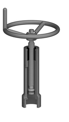
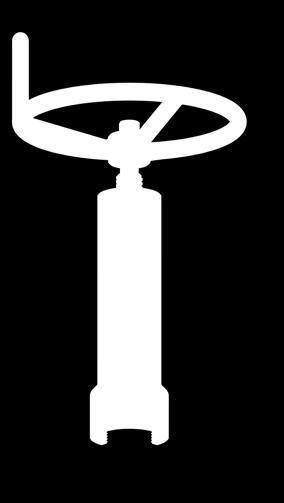
38 MANUAL OVERRIDE For Pneumatic or Hydraulic Actuator Models The Omni manual override is designed to mechanically hold open a reverse acting gate valve when well servicing, logging, testing or other intervention is required. D The Omni manual override can be installed on any Omni pneumatic or hydraulic actuator. The thrust bearing located at the end of the override stem reduces friction caused by high torque requirements and prevents damage to the actuator top shaft. A milled slot in the manual override housing allows the user to monitor the position of the override stem and determine the position of the gate valve. All components of Omni manual overrides are stainless steel or coated carbon steel to ensure operability in severe operating conditions and are available for gate valves with bore sizes from to Parts List A 5 1 Handwheel 1 2 Hex Nut 1 3 Washer 1 4 Stem 1 B Housing 1 6 Thrust Bearing 1 7 Retainer Plate 1 8 Socket Head Cap Screw 1 8 C Dimensions A B C D Weight in mm in mm in mm in mm lbs kg UN-2B THD UN-2B THD UN-2B THD Pg. 38


39 FUSIBLE MANUAL OVERRIDE For Pneumatic or Hydraulic Actuator Models The Omni fusible manual override is designed to mechanically hold open a reverse acting gate valve when well servicing, logging, testing or other intervention is required. It contains a fusible element that is designed to melt under extreme heat. This allows the actuator to close the valve in the event of a fire or other high-heat emergency. The Omni fusible manual override can be installed on any Omni pneumatic or hydraulic actuator. The thrust bearing located at the end of the override stem reduces friction caused by high torque requirements and prevents damage to the actuator top shaft. A milled slot in the manual override housing allows the user to monitor the position of the override stem and determine the position of the gate valve. 1 D 3 2 All non-fusible components of Omni fusible manual overrides are stainless steel or coated carbon steel to ensure operability in severe operating conditions and are available for gate valves with bore sizes from to Parts List 1 Handwheel 1 2 Hex Nut 1 3 Washer 1 4 Fusible Element 1 5 Stem 1 6 Retainer Plate 1 7 Retainer Ring 1 8 Bearing 1 9 Socket Head Cap Screw 1 10 Housing 1 A B C Dimensions A B C D Weight in mm in mm in mm in mm lbs kg UN-2B THD UN-2B THD UN-2B THD Pg. 39

40 SHIPPING CAP For Pneumatic or Hydraulic Actuator Models The Omni shipping cap is designed to mechanically hold the valve in the partially open position for the purpose of storage and shipping. The cap also serves to protect the upper indicator shaft and upper adapter from damage. The Omni shipping cap can be installed on all Omni safety actuators. The shipping cap should only be used during storage and shipment. It should never be installed on a valve during testing or while in service. The valve body should never be pressurized while the shipping cap is installed. The construction material is low carbon steel. The shipping cap has been coated to prevent corrosion during storage and shipment. CAUTION: Do not remove the shipping cap from an Omni actuator without an application of minimum operating pressure. Failure to perform this sequential operation could result in injury to personnel. It is not recommended to use the manual lock open device when hydrostatically testing API 6A gate valves and actuators. Note: For wire cutting applications it is recommended that the Omni Fusible Manual Override be furnished. B A C Dimensions A B C Weight in mm in mm in mm lbs kg UN-2B THD UN-2B THD Pg. 40
, the fusible element will soften allowing the valve to return to the fully closed position.")
41 FUSIBLE LOCK OPEN CAP For Pneumatic or Hydraulic Actuator Models The Omni fusible lock open cap is designed to hold a reverse acting gate valve in the fully open position. When temperature exceeds 400 F (204 C), the fusible element will soften allowing the valve to return to the fully closed position. Gate valve pressure is not necessary in forcing the valve to the closed position, as the actuator spring force provides sufficient force to close the gate valve. This fusible lock open device is adjustable and can be adapted to sizes of gate valves with strokes from 1 13 / /16. The Omni fusible lock open cap can be installed on any pneumatic or hydraulic actuators. This device can be used on 1 13 /16" through 7 1 /16" gate valves with working pressures up to 10,000 psi. CAUTION: Do not remove the fusible lock open device from an Omni actuator without an application of minimum operating pressure. Failure to perform this sequential operation could result in injury to personnel. Note: This product is designed to meet API 6A latest edition section Dimensions A B Weight in mm in mm lbs kg Dimensions - Interface Thread Item in mm 2.50 x 8 UN 2B THD x 8 UN 2B THD Parts List 1 Fusible Element 1 2 Adjustment Nut 1 3 Body 1 4 Retainer Plate 1 5 Socket Head Cap Screw 1 Specifications Item US Metric Fusible Temperature 400 F 204 C Maximum Allowable Thrust 30,000 lbf. 133,447 N A B Pg. 41
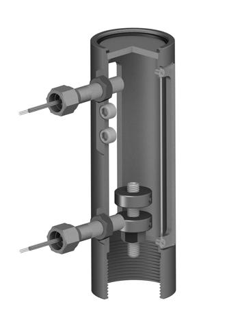
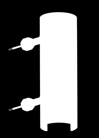
42 LIMIT SWITCH & POSITION INDICATOR The Omni Limit Switch & Position Indicator assembly is designed to electronically monitor valve stroke position. This assembly can be adapted to either reverse or direct acting gate valves. This limit switch assembly is configured to accommodate a number of actuator and gate valve sizes. The assembly can be designed to adapt to all Omni pneumatic or hydraulic actuators. 10 A Two ferrous components mechanically attached to the upper shaft, activate limit switches when the valve is in either the fully open or fully closed position. The switches may be adjusted to compensate for valve size and stroke. Dual windows are provided for monitoring of valve stroke. Protective coverings for viewing are manufactured of polycarbonate material. The material construction for the leverless limit switch is 316 stainless steel. Housing construction and top plate are manufactured from carbon steel and coated for protection against severe service conditions B Dimensions A B in mm in mm UN 2B THD UN 2B THD Limit Switch Specifications Specifications are for our standard switch. Omni offers a wide variety of switches that may exceed our stated maximums or differ from listed sensing range. Maximum Voltage Maximum Amperage Contact Form Sensing Range Enclosure Material 120 VAC / 24 VDC 4 AC / 3 DC (SPDT) Single Pole Double Throw, Form C.100" (3mm) 316 Stainless Steel Approvals UL Class 1 - Div. 1, CSA Class 1 - Div. 1, ATEX Zone 1 Operating Temperature range Response Time Suitable Zone Explosion Proof 0,1,2 Wiring Options -40 to 221 F 8 milliseconds 36 Leads 18 Gauge Standard Greater lengths available in wire or cable upon request Parts List 1 Housing 1 2 Switches 2 3 Window Shield 2 4 Switch Target 2 5 Stem Extension 1 6 Socket Set Screws 2 7 Flat Head Socket Screw 4 8 Socket Head Set Screw 2 9 Nut 1 10 Retainer Ring 1 11 Top Cover 1 Pg. 42


43 HYDRAULIC CONTROL SOLUTIONS Pg. 43


44 HYDRAULIC CONTROL SOLUTIONS Model EX - Self Contained Unit Hydraulic Intro The Omni Model EX is a self-contained hydraulic control system designed to control hydraulically-actuated reverse acting slab gate valves with a fail-safe mode of operation. The system is rugged, compact and easy to access in a field service environment. Components are designed to perform well and provide years of trouble free service even in the harshest of operating conditions. The system energizes the actuator using its own hydraulic fluid reservoir. There is no need for access to a hydraulic power source at the wellsite or wherever the actuated valve is deployed. This makes it ideally suited for deployment in remote locations or locations with limited power source options. The system is energized by operating a hand pump and can be taken off line manually or automatically. Once the system is taken off-line it must be re-energized manually using the hand pump. The Model EX system is most commonly deployed as a complete valve/actuator/control system package using Omni Valve s complete line of fail-safe hydraulic valves; however, the system can also be easily adapted to control hydraulic valves from any valve manufacturer. Horizontal Mount Depicted System Specifications Temperature Range ( F) -20 to 180 Reservoir Capacity (in^3) 120 Maximum Operating Pressure (psi) 3,000 (See Note) HP Accumulator Capacity (in^3) 20 Pump Displacement (in^3) 0.38 Note: The Model EX comes standard with a machined aluminum block offering a maximum operating pressure of 3,000 psi. If actuator control pressure exceeding 3,000 psi but not to exceed 5,000 psi is required, the Model EX can be supplied with a machined steel manifold block. Omni s standard pump displacement is 0.38 in3 but alternative displacements are available. Please contact Omni Valve for additional information Pg. 44


45 HYDRAULIC CONTROL SOLUTIONS Model EX - Self Contained Unit Features Manifold Block Design: Model EX systems are constructed using a machined block style manifold for attachment of all required components. This eliminates the need to use pipe and compression fittings to connect the various system components to one another. The result is a system with fewer potential leak paths, a more compact space envelope and reduced sensitivity to vibration or other service or handling factors that might otherwise loosen connections between components and introduce leaks. Fully Enclosed Cabinet with Locking Latch: The Model EX system bolts directly onto the hydraulic valve actuator and is fully enclosed with a hinged cabinet that can be secured in the closed position and locked, if needed. This prevents damage to or loss of the cover after opening and ensures minimal infiltration of dirt, water, animals or other external irritants that could affect system performance. Horizontal or Vertical Mounting: The Model EX system can be used regardless of whether the actuated valve is mounted in the horizontal or vertical position in the field. In either case the system functions identically. Multiple Pressure-Sensing & Control Configurations: The Model EX system is capable of being configured in multiple ways depending on the pressure sensing and connectivity requirements of the wellsite. Vertical Mount Depicted Shown with high and low pressure pilots & optional limit switch assembly Some options include: High or Low Pressure Pilots (or both) Solenoid Valve (12, 24 or other vdc electric) Combination of Pilots and Solenoid Internal/External or Both Pressure Gauges Connectivity to SCADA or Other Controls Ease of Operation: The Model EX system is designed to be easily taken off line or re-started with minimal training. Pg. 45
46 HYDRAULIC CONTROL SOLUTIONS Model EX - Internal Configuration Hydraulic The views below depict our standard configuration that employs an electronic solenoid for remote emergency shut down operation as well as a manual valve for local emergency shut down operations. This is the most common application for our EX unit. Many other configurations are available including: other methods of ESD devices, larger accumulators, eutectic fusible plugs. These various options may affect the appearance of the delivered product. Depicted without cover to display internal components Front View Back View Left View Right View Item Component Description 1 Pump A manual hydraulic pump used to build pressure in the system. 2 Accumulator Uses pressurized gas to compensate system pressure for ambient temperature changes. 3 Gauge Displays pressure of high pressure actuator line. 4 Regulator Reduces pressure for use in pilot line. 5 Manual valve Manual valve to trip the system. 6 Solenoid valve Solenoid valve to trip the system. 7 Logic element Holds pressure in the high pressure actuator line while pilot pressure is present. 8 Pressure relief Relief to compensate for over pressurization due to ambient temperature increase. 9 Kick down Allows pilot pressure to build on system start up. Used in place of manual priming valve. 10 Actuator port Connection to hydraulic actuator. 11 Suction port Connection to tank for pump suction. 12 Return Port Connection to tank for system return 13 Filter Filters the incoming hydraulic fluid Pg. 46
47 HYDRAULIC CONTROL SOLUTIONS Model EX - Circuit Diagram Gauge Accumulator Filter Element Pump 2 1 Logic Element EXT 1 3 Regulator Pressure Relief 1 Actuator Inlet Filter Kick Down Solenoid Valve Manual Valve High Pressure Suction Pilot Pressure Drain Pg. 47
48 HYDRAULIC CONTROL SOLUTIONS Model EX - Enclosure Dimensions Hydraulic A B F E D C A B C D E F 9 in 9 in 18 in 9.75 in 2.30 in in Model EX Shown with Pilots & Gauge Pilot Pilot Pilot Pilot Gauge Pg. 48
49 HYDRAULIC CONTROL SOLUTIONS Model EX - Standard Omni Valve Dimensions C B A Size Pressure A B C in mm in mm in mm 2, /5, , /5, , , , , , , , , , , , , Size Pressure A B C in mm in mm in mm 10, , , , , , , , , , Pg. 49


50 Global Energy Market Solutions HYDRAULIC / PNEUMATIC Actuators & Surface Safety Valves OMNI VALVE 4520 Chandler Road Muskogee, OK USA sales@omnivalve.com quality@omnivalve.com Omni Valve Company, LLC, BRO-ACT Rev: 1.2
MODEL DX Pneumatic Diaphragm Actuator
 MODEL DX Pneumatic Diaphragm Actuator FEATURES Flexibility Model DX actuators can be adapted to operate valves from any manufacturer (interface information is required) and can be assembled in single or
MODEL HX. Fail Safe Hydraulic Actuator FEATURES INTRO AVAILABLE SIZES. Hydraulic Actuation
 MODEL HX Fail Safe Hydraulic Actuator FEATURES Flexibility Model HX actuators can be adapted to operate valves from any manufacturer (interface information is required) and can be delivered with alternate
Expanding & Slab Gate Valves
 Global Energy Market Solutions CAST / FORGED BODY Expanding & Slab Gate Valves For oil and natural gas wellhead, flowline, manifold, fracture or other critical service applications requiring operating
WellGuard TM HWG-HL Piston Hydraulic Actuator
 WellGuard TM HWG-HL Piston Hydraulic Actuator Actuation for API 6A and 6D through conduit gate valves. For shut down (reverse acting) or blow down (direct acting) applications. Oil treating and de-salting
Oilman Group API 6A PRODUCTS OILMAN GROUP LTD. Shanghai Houston
 API 6A PRODUCTS OILMAN GROUP LTD 1 BOMCO Guanghan Drilling & Production Equipment Factory is a subsidiary of CNPC and provides the best API 6A & 16A products to esteemed customers all over the world. 2
NEECO PRODUCT CATALOGUE (FLN/FLSN)
") PLEASE READ THE FOLLOWING TERMS AND CONDITIONS CAREFULLY: The copy, reproduction, distribution, publication, display, modification, creation of derivative works, transmition, of any content on this catalog
PLEASE READ THE FOLLOWING TERMS AND CONDITIONS CAREFULLY: The copy, reproduction, distribution, publication, display, modification, creation of derivative works, transmition, of any content on this catalog
Lined Valves for High-corrosion and Heavy Capacity. Electronic Data Testing Centre For High Pressure Oil Gas Seal 15000PSI XMAS TREE UP DOWN TOP
 Lined Valves for High-corrosion and Heavy Capacity 15000PSI XMAS TREE Electronic Data Testing Centre For High Pressure Oil Gas Seal MSP/DRILEX (China) Inc. INTRODUCTION WB Ball Valves ZN Choke Valves (Needle
API 6A Gate Valves. an ARRAY Products Group company
 API 6A Gate Valves valves for wellhead, manifold, distribution and fracture applications an ARRAY Products Group company TABLE OF CONTENTS Valve Trim Chart... 2 2,000 5,000 PSI Expanding or Slab Gate
Wellhead Valves. DHV Industries,Inc. DHV Valve Company Inc.
 DHV Industries,Inc. 3451 Pegasus Drive, Bakersfield. CA 93308 U.S.A. Call TollFree: (887) DHV-USA1 Phone: (661) 392-8948 Fax: (661) 392-8947 E-mail: sales@dhvindustries.com Website: www.dhvindustries.com
PWP Series - PressureGuard Wellhead Protection
 PWP Series - PressureGuard Wellhead Protection Self-Contained Hydraulic Emergency Shutdown Valve System API 6A Design/Operation Bettis PWP TM series is a self-contained hydraulic emergency shutdown system.
MAGNUM GATE VALVES. Invention, Unique Design & Extraordinary Craftsmanship. WORLDWIDE OILFIELD MACHINE Est. 1980
 TM MAGNUM GATE VALVES www.womusa.com Invention, Unique Design & Extraordinary Craftsmanship WORLDWIDE OILFIELD MACHINE Est. 980 Table of Contents Patented Dual-Seal Technology Magnum Gate Valve 2 Magnum
FRAC STACKS stingercanada.com
 FRAC STACKS stingercanada.com Grande Prairie 11303 96 Avenue Grande Prairie, AB T8V 5M3 780-513-3696 Calgary 420-510 5th Street SW Calgary, AB T2P 3S2 403-340-0716 Red Deer 334-28042 Hwy 11 Red Deer County,
OPERATION & MAINTENANCE MANUAL API 6A SLAB GATE VALVE AAS-013 REV C
 OPERATION & MAINTENANCE MANUAL API 6A SLAB GATE VALVE AAS-013 REV C TABLE OF CONTENTS I. Introduction............................................. 3 II. Installation and Operating Instructions..............................
MODEL APH HYDRAULIC ACTUATOR
 OPERATION & MAINTENANCE MANUAL MODEL APH HYDRAULIC ACTUATOR TABLE OF CONTENTS I. Introduction............................................. 3 II. Actuator Operation.........................................
HIGH PRESSURE CONTROL VALVE PISTON BALANCED
 PISTON BALANCED All Rights Reserved. All contents of this publication including illustrations are believed to be reliable. And while efforts have been made to ensure their accuracy, they are not to be
Valveworks USA Operation and Maintenance Booklet Model FC
 Operation and Maintenance Booklet Model FC MODEL FC 3000, 5000, 10000, & 15000 W.P. FLOATING SLAB GATE VALVES 1 13/16-2 1/16-2 9/16-3 1/16-4 1/16 BOOKLET APPROVED BY: INTRODUCTION In appreciation to you
MODEL 5540 CONTENTS. Installation, Operation and Maintenance Instructions 1.0 GENERAL
 Installation, Operation and Maintenance Instructions MODEL 5540 Sep 20 CONTENTS.0 GENERAL. Model Number---------------------------------------------------------------------------------------------------------------
Surface Safety Valves Protecting Your Personnel, Facilities, Environment and Natural Resources
 Protecting Your Personnel, Facilities, Environment and Natural Resources Crown Hydraulic Surface Safety Valve System Stream-Flo s Crown Self-Contained Hydraulic Surface Safety Valve Actuation System is
T BOP. prep. TC Cooper Cameron, Cameron Division
 T BOP The Cameron T blowout preventer offers a unique combination of benefits including safety, economy, reliability, extended service life, reduced height and fast and easy service. Side ram removal on
TABLE 1 - PRODUCT FEATURES. MODEL FM4 MODEL FM4 SG MODEL FM4 RC MODEL FM4 RC SG MODEL FM4 BSOP f MODEL FM4 RC BSOP f 7 1/16 2K, 3K, 5K MECHANICAL
 GATE VALVES FM4 SERIES OVERVIEW The Valveworks USA FM4 Series consists of a lineup of gate valves with reliale, proven designs that are engineered and manufactured to meet the requirements of API 6A, and
Delivering Peak Performance. High-pressure liquid and gas flow control solutions for the oil and gas industry s harshest environments
 Delivering Peak Performance High-pressure liquid and gas flow control solutions for the oil and gas industry s harshest environments A leading brand of high pressure valves, tubing, fittings and accessories,
Slab & Double Expanding Gate Valves
 Slab & Double Expanding Gate Valves Double Expanding Characteristics The main feature of a double expanding gate valve is the 2 pieces obturator that guarantees a simultaneous mechanical seal both in the
COMPREHENSIVE OVERVIEW
 COMPREHENSIVE OVERVIEW stingercanada.com 3 About Stinger 5 Ball Launchers 10 Frac Stacks 17 Buffalo Heads 18 Isolation Tools Grande Prairie 11303 96 Avenue Grande Prairie, AB T8V 5M3 780-513-3696 Calgary
PRODUCT OVERVIEW. Our BDB (Bolted Body) and BW3 (Fully Welded Body) trunnion-mounted ball valves are designed and manufactured
 and BW3 (Fully Welded Body) trunnion-mounted ball valves are designed and manufactured") PRODUCT OVERVIEW For over 30 years, FluoroSeal has been manufacturing and customizing a wide range of valves, and accessories for many industries including Oil & Gas, Petrochemical, Chemical, Mining, Pharmaceutical,
PRODUCT OVERVIEW For over 30 years, FluoroSeal has been manufacturing and customizing a wide range of valves, and accessories for many industries including Oil & Gas, Petrochemical, Chemical, Mining, Pharmaceutical,
Type MR105 Direct-Operated Pressure Reducing Regulators
 Instruction Manual Form 5874 Type MR105 December 2014 Type MR105 Direct-Operated Pressure Reducing Regulators Contents Introduction...2 Specifications...2 Principle of Operation...3 Installation...4 Overpressure
Fisher 2052 Diaphragm Rotary Actuator
 Instruction Manual 2052 Actuator Fisher 2052 Diaphragm Rotary Actuator Contents Introduction... 1 Scope of Manual... 1 Description... 1 Specifications... 4 Installation... 4 Actuator Mounting and Changing
Your Global Flow Control Partner. Series 92/93 Pneumatic Actuators. Technical Manual
 Your Global Flow Control Partner Series 92/93 Technical Manual TM-1056 Pneumatic Actuator - 04/18/2017 Bray Series 92/93 Technical Manual - Table of Contents Topic...Page(s) Actuator Installation Notes...
Fast, Effective Blowout Protection
 Dual or Single Ram Hydraulic BOPs Fast, Effective Blowout Protection MODEL DRH - DUAL RAM HYDRAULIC BOP Guide Rib Pipe Centering Guide Ram Rubber Pipe Ram Block Door Cylinder Locking Shaft Lip-Type Piston
D and DL Annular Blowout Preventers
 D and DL Annular Blowout Preventers In the unique design of the Cameron DL Annular BOP, closing pressure forces the operating piston and pusher plate upward to displace the solid elastomer donut and force
Lexington Valve Parts
 Lexington Valve Parts Chokes 2012 Catalog sales@lexingtonvalveparts.com Phone: 832-507-9701 1 TABLE OF CONTENTS Choke Selection Information 3 Positive and Adjustable Chokes 4 How to Order 5 Positive/Adjustable
Crown Actuated Valves & Controls
 Protecting Your Personnel, Facilities, Environment and Natural Resources Crown Self-Contained Hydraulic Valve Actuation System Stream-Flo s Crown self-contained hydraulic valve actuation system is used
Electronic Control Valves
 MODEL 131 Series (Full Internal Port) 631 Series (Reduced Internal Port) Electronic Control Valves Model 131-01/631-01 Simple Proven Design Quality Solenoid Pilot Controls Ideal For SCADA Systems Multi-Function
WKM 320F. Flanged floating ball valves
 WKM 20F Flanged floating ball valves Contents WKM 20F Flanged Floating Ball Valves Features and benefits.................................................................... Exploded views and specifications....................................................5
Model DFLP Linear Actuator
 Features Rugged Long Lasting Construction Dyna-Flo s expert CNC machining process and superior quality parts come together to make DFLP actuators a rugged, long lasting product. DFLP actuators are manufactured
NEECO INDUSTRIES INC. INSTRUCTION MANUAL 7 1/16 10K SLAB GATE BODY
 INSTRUCTION MANUAL 7 1/16 10K SLAB GATE BODY INTRODUCTION The NF-700 type gate valves provided by Neeco Industries are full-bore through conduit non-rising stem manually (w/ball screw) operated valves.
Delivering innovation through engineering
 Delivering innovation through engineering +44 1224 727480 Completions & Work-over Operations Bore Selector gives access to either the main production bore or annulus in a traditional vertical xmas tree,
SUNNDA CORPORATION. Pressure Control Equipment. Boost Your Bottom Line! Sunnda Corporation
 SUNNDA CORPORATION Boost Your Bottom Line! Pressure Control Equipment Sunnda Corporation 4543 Brittmoore Road, Houston, TX 77041 USA Phone: +1-713-849-5678 Fax: +1-713-849-5687 E-mail: sales@sunnda.com
6200 Series. Specifications. Fluid End Power End Models 6211, 6212, 6221, & 6222 Models 6241 & 6242 Part Material Part Material Part Material
 5.2018.12.i 6200 Series Specifications The Flomore 6200 Series Pump line consists of a series of basic pump options all developed from a modular power unit. All units are pneumatically driven positive
REMEMBER... SAFETY FIRST, EVERY TIME
 SIZE: 3.00 FEBRUARY 19, 2019 REV: 1.2 Page 1 of 10 REMEMBER... SAFETY FIRST, EVERY TIME Always use eye protection when using power tools. Always wear protective footwear when working in a workshop environment.
Mud Pump (Emsco Type) Diesel Engine
 Diesel Engine") Houston: +1 713-893 - 5018 Beijing: +86 10 82898786 E-mail: info@cppipe.com Website: www.cppipe.com www.cppipe.cn CP Pipe & Equipment Corporation (CP) is a major US supplier of tubular products, petroleum
Houston: +1 713-893 - 5018 Beijing: +86 10 82898786 E-mail: info@cppipe.com Website: www.cppipe.com www.cppipe.cn CP Pipe & Equipment Corporation (CP) is a major US supplier of tubular products, petroleum
VB VALVES & AUTOMATION
 Introduction to Valve What are Valves? Valves are mechanical device that controls the flow and pressure within a system or process. They are essential components of a piping system that conveys liquids,
Model 5-025, 5-050, &
 Model 5-025, 5-050, 5-075 & 5-150 7 Model 5-025, 5-050, 5-075 & 5-150 8 Eductor Block Exploded View Model 5-025, 5-050, 5-075 & 5-150 9 Figure 1 Item Part Name Model Model Model Model 5-025 5-050 5-075
Jordan Control Valve Series
 Jordan Control Valve Series Control Valves A control valve is used to manipulate flowing fluids like, gas, water, steam or process solutions. It compensates for changes in flow or pressure and regulates
MODEL 106/206-PG POWER OPERATED GLOBE VALVE Sizes 1/2" to 8" (106-PG) 3" to 10" (206-PG) Installation, Operating and Maintenance Instructions
 3 to 10 (206-PG) Installation, Operating and Maintenance Instructions") MODEL 106/206-PG POWER OPERATED GLOBE VALVE Sizes 1/2" to 8" (106-PG) 3" to 10" (206-PG) Installation, Operating and Maintenance Instructions DESCRIPTION: This valve is the basic component used for most
MODEL 106/206-PG POWER OPERATED GLOBE VALVE Sizes 1/2" to 8" (106-PG) 3" to 10" (206-PG) Installation, Operating and Maintenance Instructions DESCRIPTION: This valve is the basic component used for most
VALVEWORKS USA OPERATION AND SERVICE MANUAL FOR MODEL FC GATE VALVES MODEL FC PSI W.P FLOATING SLAB GATE VALVES
 OPERATION AND SERVICE MANUAL FOR MODEL FC GATE VALVES MODEL FC 3000-15000 PSI W.P FLOATING SLAB GATE VALVES INTRODUCTION In appreciation to our customer for purchasing our product, we have prepared this
PBV s Engineering Excellence At Work
 PBV s Engineering Excellence At Work The PBV Series 5700/6700 Three-Piece, Side-Entry, Trunnion Ball Valve 2"- 56" ANSI Class 150/300,600,900,1500 & 2500 In Full And Standard Port PBV trunnion ball valves
TL BOP. TL Custom Features:
 TL BOP The Cameron TL BOP product line is the result of an evolution of Cameron s successful U, UII and T BOPs combined with custom features based on each customer s specific requirements. All TL BOPs
RAM Company USA Products Line
 RAM Company USA Products Line Trunnion Mounted Ball Valves Metal Seated Ball Valve 3-Way Ball Valve Jacket Ball Valve Ball Valves with Actuator Trunnion Mounted Ball Valves Main Features DOUBLE PISTON
International Standard Valve, Inc. Slab and Expanding Gate Valves
 International Standard Valve, Inc. TM ISV Series GTDS & GTDE Slab and Expanding Gate Valves 2 through 36 ASME Class 150-2500 Top Entry Bolted Body Flanged & Weld Ends API 6D Fire Safe Design NACE is a
API6A Valves products CATALOG
 API6A Valves products CATALOG INDEX 1. DFC TYPE GATE VALVE 2. DF TYPE PARRALLEL GATE VALVE 3. DWKM TYPE EXPANDING GATE VALVE 4. MUD GATE VALVE 5. CAGE CHOKE VALVE 6. ORIFICE CHOKE VALVE 7. POSITIVE CHOKE
Baumann Way Control Valve
 Instruction Manual 24003 Valve Baumann 24003 3-Way Control Valve Contents Introduction... 1 Scope of Manual... 1 Safety Precautions... 2 Educational Services... 3 Maintenance... 3 Installation... 3 Air
TABLE 1 - PRODUCT FEATURES 2 1/16 2K,3K,5K 2 9/16 2K,3K,5K 3 1/8 2K,3K,5K 4 1/16 2K,3K,5K 5 1/8 2K,3K,5K -75 F (-60 C) THRU 250 F (121 C)
 THRU 250 F (121 C)") VALVES M SERIES OVERVIEW Te Valveworks USA M series consists of a lineup of gate valves wit reliable, proven designs tat are engineered and manufactured to meet te requirements of API 6A. Tis series of
VALVES M SERIES OVERVIEW Te Valveworks USA M series consists of a lineup of gate valves wit reliable, proven designs tat are engineered and manufactured to meet te requirements of API 6A. Tis series of
SWING CHECK VALVES SERIES 52-SC SERIES 600
 SWING CHECK VALVES SERIES 52-SC SERIES 600 FEATURES/BENEFITS/SPECIFICATIONS AMERICAN Flow Control Series 52-SC Swing Check Valves incorporate design features to help increase service life for water and
D-Series Rack & Pinion Pneumatic Actuators
 D-Series Rack & Pinion Pneumatic Actuators Introduction 2 Bettis D-Series pneumatic rack and pinion actuators provide its users with reliability and economy in valve automation. Specifically designed for
MEMORY SEAL BALL VALVES MAINTENANCE MANUAL 2 12, Class 150 & 300, Regular Port, Flanged Unibody
 MEMORY SEAL BALL VALVES MAINTENANCE MANUAL 2 12, Class 150 & 300, Regular Port, Flanged Unibody I INTRODUCTION These rugged, versatile, high performance, regular port, ball valves meet all requirements
Engineered Valves For Pipeline Service Application
 Page 1 TRUNNION MOUNTED BALL VALVES TM SERIES Engineered Valves For Pipeline Service Application Valves for oil & gas pipelines and other industrial applications Flanged or Butt Weld ANSI Class 150 thru
Bimba Extruded Linear Thrusters 2X FF X EE DP 2X DD 2X Ø DD X EE DP U V W X Y Z R S Dimensions - ET T B 4X TAP AA THRU Ø BB C BORE X CC DP (OPP.SIDE)
") Bimba Extruded Linear Thrusters Engineering Specifications Maximum Operating Pressure 140 psi (10 bar) Temperature Range 15 to 160 degrees F (-10 to 70 degrees C) Expected Service Life 1,500 miles (with
Bimba Extruded Linear Thrusters Engineering Specifications Maximum Operating Pressure 140 psi (10 bar) Temperature Range 15 to 160 degrees F (-10 to 70 degrees C) Expected Service Life 1,500 miles (with
SPECIFICATIONS FOR BLEEDER PLUGS USED IN WELLHEAD APPLICATIONS
 SPECIFICATIONS FOR BLEEDER PLUGS USED IN WELLHEAD APPLICATIONS TECHNICAL REPORT TR0701 AWHEM publications may be used by anyone desiring to do so. Every effort has been made by the Association to assure
CVS 7970 High-Low Pressure Pilot
 Instruction Manual CVS 7970 High-Low Pressure Pilot Introduction This instruction manual includes the following information for CVS 7970 High-Low Pressure Pilot: 1. Description 2. Piston Arrangement Changeover
Cameron International Corporation
 Cameron International Corporation 2 Cameron International Corporation About this Catalog The purpose of this catalog is to serve as a quick reference for our customers. However, many of Cameron s products
Fisher D2T FloPro Control Valve
 Instruction Manual D2T FloPro Valve Fisher D2T FloPro Control Valve Contents Introduction... 1 Scope of Manual... 1 Description... 1 Educational Services... 2 Specifications... 3 Installation... 3 Setting
Multi Orifice Nozzle. Valve (MON) R Series Control Valves R2 R3 R4 R6 R8
 R Series Control Valves R2 R3 R4 R6 R8") Multi Orifice Nozzle (MON) Valve R Series Control Valves R2 R3 R4 R6 R8 R Series Control Valves www.taylorvalve.com The applied principle of Hydrodynamic Energy Conversion Protective Cage and Seat Assembly
Multi Orifice Nozzle (MON) Valve R Series Control Valves R2 R3 R4 R6 R8 R Series Control Valves www.taylorvalve.com The applied principle of Hydrodynamic Energy Conversion Protective Cage and Seat Assembly
Type EZR Relief Valve or Backpressure Regulator
 Instruction Manual Form 5476 Type EZR Relief October 2015 Type EZR Relief Valve or Backpressure Regulator W7347 Figure 1. Type EZR Relief Valve or Backpressure Regulator Introduction Scope of the Manual
MAR031615A 1. PABD Installation & Maintenance. Guide *Parts will differ for high pressure valves.
 MAR031615A 1 PABD Installation & Maintenance Guide *Parts will differ for high pressure valves. Load Piston U-cup - Piston - U-cup Piston 1. Carefully place the u-cup over the neck of the piston. Load
CVS Series 35, 50, 60, 70. Scotch Yoke Hydraulic Actuators. Introduction. Instruction Manual
 Instruction Manual Figure 1: CVS Series 35 SRM100 Actuator CVS Series 35, 50, 60, 70 Scotch Yoke Hydraulic Actuators Introduction The CVS Hydraulic Actuator uses a scotch yoke mechanism to convert linear
MAINTENANCE MANUAL DS3 DOUBLE SHEAR LOCKOUT UNIT
 ENGINEERED PRODUCTS ISO 9001 REGISTERED MAINTENANCE MANUAL DS3 DOUBLE SHEAR LOCKOUT UNIT 70mm BORE PNEUMATIC CYLINDER DOUBLE ROD SHOWN LOCKOUT DISK* SOLID STATE CYLINDER * *OPTIONAL SHEET 1 REV 2/14/2018
Spring Return and Double Acting Pneumatic Quarter-turn Actuators Operations Manual
 Spring Return and Double Acting Pneumatic Quarter-turn Actuators Operations Manual Table of Contents General..................... 1 Pneumatic Recommendations... 1 Construction................. 2 Disassembly
DO NOT INSTALL, OPERATE, OR MAINTAIN AN ATI PRODUCT UNLESS TRAINED AND QUALIFIED IN PRODUCT AND ACCESSORY INSTALLATION, OPERATION AND MAINTENANCE.
 IOM Supplement IOMS003 ATI HO1/HO2 HYDRAULIC OVERRIDE Scope of Supplement This supplement is intended to assist those who are involved with the installation, operation and maintenance of ATI Linear Actuators
Bulletin 1494C Cable Operated Disconnect Switch Kit (400A) Installation Instructions (Cat 1494C- _ Series 2 : 400A)
 Installation Instructions (Cat 1494C- _ Series 2 : 400A)") Bulletin 494C Cable Operated Disconnect Switch Kit () Installation Instructions (Cat 494C- _ Series : ) ATTENTION: To prevent electrical shock, disconnect from power source before installing or servicing.
Bulletin 494C Cable Operated Disconnect Switch Kit () Installation Instructions (Cat 494C- _ Series : ) ATTENTION: To prevent electrical shock, disconnect from power source before installing or servicing.
CONTROL VALVES. Installation, Maintenance & Operating Instructions. Read these instructions carefully before installation or servicing.
 KOSO HAMMEL DAHL CONTROL VALVES KOSO HAMMEL DAHL 253 Pleasant Street West Bridgewater, MA 02379 tel: 774.517.5300 fax: 774.517.5230 www.hammeldahl.com Installation, Maintenance & Operating Instructions
TY-FLO 3 Piece Ball Valves
 TY-FLO 3 Piece Ball Valves 3 PIECE BALL VALVES TY-FLO 3 Piece Ball Valves D 1 ASME B16.34 Compliant FEATURES 3-Piece, 8-Bolt construction provides superior high pressure performance and ASME B16.34 compliance
Material Specifications
 5.2012.12.b 6200 Series Specifications The Flomore 6200 Series Pump line consists of a series of basic pump options all developed from a modular power unit. All units are pneumatically driven positive
Products for the Oil & Gas Industry
 Products for the Oil & Gas Industry BuTech a leading brand of high pressure valves, tubing, fittings and accessories, takes a proactive stance on the design, development and production of new and existing
Baumann Little Scotty Bronze Control Valve
 Instruction Manual 24000 Valve Baumann 24000 Little Scotty Bronze Control Valve Contents Introduction... 1 Scope of Manual... 1 Safety Precautions... 2 Maintenance... 2 Installation... 3 Air Piping...
 ACADs (08-006) Covered 1.3.1.7 1.3.9.2 2.1.6.1 2.1.6.2 2.1.6.4. 2.1.7.1 2.1.7.2 2.1.7.6 5.2.1.10 5.4.1.4 5.4.3.5 Keywords Gate, ball, butterfly, diaphragm, globe, regulate, throttle, back flow, relief,
(Interchangeable with Demco Model DM Gate Valve)
") DM GATE VALVE (Interchangeable with Demco Model DM Gate Valve) The DM Gate Valve, are solid gate, rising stem, gate valves with resilient seals. They are purpose made for mud, cement, fracturing and water
DM GATE VALVE (Interchangeable with Demco Model DM Gate Valve) The DM Gate Valve, are solid gate, rising stem, gate valves with resilient seals. They are purpose made for mud, cement, fracturing and water
GWC Italia. Proven technology for individual valve solutions worldwide WGV-1002
 GWC Italia Proven technology for individual valve solutions worldwide api 6a gate valves WGV-1002 2 GWC ITALIA Proven technology for individual valve solutions worldwide w w w. g w c i t a l i a. c o m
Model DFC and DFO Valve Actuator
 Features Reliable Design Formed diaphragm has no friction with other moving parts allowing maintenance free operation through years of constant cycling. Protective Coatings External surfaces are either
W E L L S I T E S E R V I C E S
 WELL SITE SERVICES TABLE OF CONTENTS Frac Stack and Flow Control High Pressure Sand Removal System...FSFC-1a-d SPS Type 7 Manual and Hydraulic Frac Valve...FSFC-2a-b Frac Stacks...FSFC-3 High Pressure
AV INSTALLATION, OPERATION & MAINTENANCE MANUAL
 Rack & Pinion Pneumatic Actuators AV INSTALLATION, OPERATION & MAINTENANCE MANUAL AVCS PO Box 68172 Minneapolis, MN 55418 TABLE OF CONTENTS CHAPTER 1: PRODUCT DESCRIPTION 3 CHAPTER 2: TECHNICAL FEATURES
TY-FLO 3 Piece Ball Valves
 OTHER PRODUCTS Other Products TYLOK International carries a comprehensive range of high-quality fluid components to compliment the TY-FLO 3 Piece Ball Valve product line. Featured below are several popular
Fisher 3024C Diaphragm Actuator
 Instruction Manual 3024C Actuator Fisher 3024C Diaphragm Actuator Contents Introduction... 1 Scope of Manual... 1 Description... 2 Specifications... 3 Installation... 5 Mounting the Actuator on the Valve...
Back Pressure Regulator
 Instruction Sheet P/N 108652H Description The Nordson back pressure regulator is a spring-loaded, hand-operated fluid pressure regulator designed for use with general liquid coating materials. The regulator
LOW PRESSURE BALANCED VALVE DIAPHRAGM BALANCED
 DIAPHRAGM BALANCED All Rights Reserved. All contents of this publication including illustrations are believed to be reliable. And while efforts have been made to ensure their accuracy, they are not to
Type EZR Relief Valve or Backpressure Regulator
 Instruction Manual Form 5476 Type EZR Relief May 2012 Type EZR Relief Valve or Backpressure Regulator Introduction Scope of the Manual W7347 This instruction manual provides installation, startup, shutdown,
Y690A Series Pressure Reducing Regulators
 Instruction Manual Form 5463 Y690A Series April 1999 Y690A Series Pressure Reducing Regulators Introduction Scope of Manual This manual provides instructions for installation, startup, maintenance, and
Linear Thrusters/PneuMoment
 /PneuMoment Extruded 3.3-3.10 TE Series 3.11-3.16 T Series 3.17-3.22 3.23-3.24 3.25-3.28 3.29-3.32 PneuMoment Pneumatic Actuators PneuMoment Application 3.33 3.34-3.48 3.49 Bimba 304 stainless steel body
Linear Thrusters/PneuMoment
 /PneuMoment Extruded 3.3-3.10 TE Series 3.11-3.16 T Series 3.17-3.22 3.23-3.24 3.25-3.28 3.29-3.32 PneuMoment Pneumatic Actuators PneuMoment Application 3.33 3.34-3.48 3.49 Pneu-Moment Bimba Pneu-Moment
Baumann 24000F Wafer Control Valve
 Instruction Manual 24000F Valves Baumann 24000F Wafer Control Valve Contents Introduction... 1 Scope of Manual... 1 Safety Precautions... 2 Maintenance... 2 Installation... 3 Air Piping... 3 Disassembly...
Model DF269 Control Valve
 Figure 1 DF269 Control Valve TABLE OF CONTENTS Introduction 2 Fail Open Actuator Disassembly 6 General 2 Body and Packing Reassembly 7 Scope 2 Fail Closed Actuator Resassembly 8 Specifications 3 Fail Open
Multiple Orifice Valve Chokes Precision flow control in a range of applications around the world
 Multiple Orifice Valve Chokes Precision flow control in a range of applications around the world Contents MOV chokes................................................................................2 Multiple
Pilot-Operated Regulators
 Fisher Controls Instruction Manual Type 1098-EGR & 1098H-EGR Pilot-Operated Regulators R May 1987 Form 5084 Contents Introduction................................... 2 Scope of Manual..............................
Family of Products 1100 SERIES 1500 SERIES. 3 Piece Full Port Fire Safe Ball Valve ANSI Class WOG
 Family of Products 3210 S. Susan St, Santa Ana, CA 92704 Tel (714) 427-0877 Fax (714) 427-6392 www.avcovalve.com 1100 SERIES 3 Piece Full Port Fire Safe, PCTFE, PEEK, 1500 SERIES 3 Piece Full Port Fire
Technical Manual MSI Hydraulic Adjustable Choke
 Technical Manual MSI Hydraulic Adjustable Choke MSI A Division of Dixie Iron Works, Ltd. 300 W. Main St. Alice, TX 78332 www.diwmsi.com (800) 242-0059 Revision A TABLE OF CONTENTS SECTION 1 WARNINGS...
Hard Seat Fluid Pressure Regulator
 Instruction Sheet P/N 04742-02 Description The Nordson hard seat fluid pressure regulator is designed for use with abrasive coatings. The regulator body is constructed of stainless steel with a nickel-plated
MT SERIES PNEUMATIC ROTARY ACTUATORS
 MT SERIES PNEUMATIC ROTARY ACTUATORS Toll Free 1.888.842.9998 Fax 1.866.842.3144 6 FEATURES COMPACT DESIGN The MAX-AIR rack & pinion pneumatic actuator produces linear torque output in a compact design
Double Acting & Spring Return. SERIES 92/93 Rack & Pinion PNEUMATIC ACTUATOR. The High Performance Company
 PNEUMATIC ACTUATOR SERIES 92/93 Rack & Pinion Double Acting & Spring Return The High Performance Company SERIES 92/93 Styling, strength, compactness, and simplicity of design have been combined to produce
KE Series. Through Conduit, Double Expanding Gate Valves
 KE Series Through Conduit, Double Expanding Gate Valves The KE Series is an advanced API 6D designed gate valve that provides a tight mechanically activated seal. It has double sealing, bi-directional
CHOKES API 6A & 16C Extreme Service/Drilling Chokes
 CHOKES API 6A & 16C Extreme Service/Drilling Chokes Robust Reliable Proven The Standard in Non-Standard Valve Production www.uscortec.com CORTEC Models CX3 and CXE-II Drilling/Extreme Service Chokes CORTEC
INSTALLATION, OPERATION & MAINTENANCE MANUAL
 Rack & Pinion Pneumatic Actuators INSTALLATION, OPERATION & MAINTENANCE MANUAL QSM, Inc. 127 Village Lane Easley, SC 29642 U.S.A. Ph: (864) 605-0150 Fax: (864) 605-0830 www.tru-flo.com TABLE OF CONTENTS