HH SERIES: HEAVY DUTY INDUSTRIAL HYDRAULIC TRD BIMBA. company
|
|
|
- Samson Robert Curtis
- 5 years ago
- Views:
Transcription


1 HH SERIES: HEAVY DUTY INDUSTRIAL HYDRAULIC TRD a BIMBA company


2 The TRD difference... Precision machined throughout. We started in business as precision machinists. Every component is machined in a manner to enhance the performance of our products. Cylinder tubes are lathe cut, not sawed. Heads and caps are 100% CNC machined to tight tolerances in jig bored fixtures. Piston and rod diameters and concentricity are held to within two thousandths of an inch, in CNC lathes. The results: cylinders that have a consistent performance and long life. Our cylinders are truly square, which eliminates shimming! Try the TRD difference! On time, consistent delivery. Every customer s order is important. Our business is managed so large orders do not disrupt our published delivery schedules. Cylinder Options and Custom Modifications - Since every cylinder is made to order, you can customize each cylinder to best fit your application. You can choose from our extensive list of standard options, or send us a sketch for a custom solution! Port size, type or location along with cushion locations can be made to your specifications. (All NFPA, BSP or SAE Sizes available) Rod End Styles and Designs: (6) NFPA Standard rod end styles available Custom or other thread lengths available Metric or other thread styles available Custom rod end styles available - just send us a sketch! Hollow Rod designs can be gun-drilled to your specifications Most Cylinder Options Ship in 2-3 Days! Quick response on all requests. Most requests are answered the day they are received. Visit us on the web: sales@trdmfg.com CAD FILES: CONTACT TRD FOR SPECIFIC HYDRAULIC CYLINDER MODEL DRAWINGS 3 YEAR WARRANTY TRD Manufacturing Incorporated, A Bimba Company, is an employee owned company. We take great pride in our products. TRD Manufacturing, Inc. warranties its cylinders for a full 3 years to be free from defects in material and workmanship. TRD Manufacturing, Inc. must be notified prior to returning product for warranty evaluation. Contact your local TRD distributor to obtain an RGA (Returned Goods Authorization Number) for proper tracking and expedited service on all warranty evaluations. TRD will repair or replace free of charge any products returned to the factory within 3 years of shipment that is proven to be defective in material and/or workmanship. A complete explanation of defects is required with the returned product. The TRD warranty applies only to products used properly and under normal operating conditions. All products are to be used in a safe manner, in properly designed systems. Safeguards to prevent personal injury or equipment damage must be used and are the sole responsibility of the user. In no event shall TRD Manufacturing, Inc. be liable for any consequential damages or installation costs resulting from delay or failure of delivery, defective material or workmanship or out of a breach by TRD Manufacturing, Inc. of any contract. 2
3 TABLE OF CONTENTS PAGE WARRANTY & RETURN INFO SERIES HH Construction How To Order & NFPA Mounts Rod Ends Dimension Drawings Hydraulic Rod Lock Accessories Alignment Couplers Cylinder Basic Options Cylinder Uncommon Options Balluff End of Stroke Sensors Balluff Transducers MTS Temposonics Transducers Seal Kits TECHNICAL DATA PAGE PAGE Force Chart Weight Charts Torque Charts Seal Compatibility Pressure Rating Misc. Conversion Charts Hydraulic Cylinder Speeds Fluid Power Formulas DELIVERY SCHEDULE Back Cover Basic Cylinders Rod Lock Accessories Options Sensors Seal Kits Technical Data 3

4 Technical Data Seal Kits Sensors Options Accessories Rod Lock Basic Cylinder Floating Rod Bushing SELF ALIGNMENT FEATURE Rod Bushing is designed to float.002, improving bearing surface alignment. Reduces cylinder drag and erratic operation Reduces cylinder wear Provides a minimum of 25% longer life than fixed Rod Bushing designs HEAVY-DUTY DESIGN FOR RELIABLE, CONSISTENT OPERATION ➀ FLOATING ROD BUSHING Precision machined from 150,000 PSI rated graphite filled ductile iron and PTFE coated to reduce friction and extend cycle life. Bushing design traps lubrication in effective bearing area. Bronze bushings also available. ➁ PORTS NPTF and SAE ports available standard. Nonstandard locations, sizes, and other port styles can be made to order to fit any application needs. ➂ PISTON ROD Steel piston rod provides high strength and damage resistance. Induction hardened and chrome plated for maximum wear resistance and long life. (100K min. yield up to 5 rod; 75K min. yield for 5½ rod) ➃ PISTON Precision machined ductile iron provides high strength and an excellent bearing surface for extended cylinder life. ➄ TIE RODS Pre-stressed high carbon steel tie rod construction eliminates axial loading of cylinder tube and maintains compression on tube. (100K min. yield) ➅ CUSHION Precision machined cushions are available at either end and provide smooth deceleration which helps reduce end of stroke shock. ➆ PISTON SEALS Heavy lip design Carboxilated Nitrile OPERATING PRESSURE Performance options: SERIES HH (NFPA) CYLINDER 3000 PSI HYD (207 BAR) Refer to page 51 for specific PSI RLH Rod locks are used to hold linear cylinder loads stationary in any mounting orientation during power off condition. See pages for more information. ST Stop tubes are used to reduce rod bearing and piston stress (refer to page 34 for cylinder design guidance). CS Center Supports are recommended for cylinders with long strokes in horizontal applications to prevent buckling of the cylinder and extend cylinder life. OPERATING TEMPERATURE seals with back-up rings are pressure activated and wear compensating for extended life. Cast ring, EP, PTFE, and fluorocarbon designs available. ➇ ROD WIPER Flocked nitrile wiper removes contaminants on retract stroke, helping insure long life for all internal components. ➈ ROD SEALS Polyurethane seals offer high abrasion resistance and strength. Pressure activated double lip and wear compensating for extended life. ➉ HEAD & CAP Precision machined steel head and cap are held to tight tolerances and insure accurate alignment for a truly square cylinder. TUBE Precision machined steel tube with hard chrome I.D. is honed and micro finished for extended seal life and improved cycle rates. CUSHION ADJUSTMENT NEEDLE Adjustable steel needle design has fine thread metering and is positively captured to prevent needle ejection during adjustment. PISTON ROD STUD Standard on KK1 and KK2 threads for 5 /8-2 rods (125K min. yield). Available up to 2 times standard A thread length. WEAR BAND Wear Guard Nylon (standard); reinforced PTFE for E and V seal option. Standard Seals: Fluorocarbon: -20 F to 200 F (-29 C to 93 C) 0 F to 400 F (-18 C to 204 C) SSR 17-4 Chrome Plated Stainless Steel Piston Rod provide corrosion resistance in outdoor applications and wet environments. (100K min. yield up to 5 rod; 75K min. yield 5½ rod) HP High impact pistons use a high strength steel nut retained piston for fatigue resistance and additional strength in demanding applications. 4
5 HOW TO ORDER: SERIES HH (HEAVY DUTY HYDRAULIC CYLINDERS) HH MX0 MF1 MF2 MF5 MF6 ME5 ME6 MP1 MS2 MS3 MS4 MS7 MT1 MT2 MT4 MX1 MX2 MX3 HH - MF1-250 x 10 - H2C KK1 - P15 = N375 - S S S S - SERIES HEAVY DUTY HYDRAULIC NFPA MOUNTS NO MOUNT (1.50 to 8.00 Bore) HEAD RECTANGULAR FLANGE (1.50 to 6.00 Bore) CAP RECTANGULAR FLANGE (1.50 to 6.00 Bore) HEAD SQUARE FLANGE (1.50 to 8.00 Bore) CAP SQUARE FLANGE (1.50 to 8.00 Bore) HEAD RECTANGULAR MOUNTING HOLES (1.50 to 8.00 Bore) CAP RECTANGULAR MOUNTING HOLES(1.50 to 8.00 Bore) FIXED CAP PIVOT CLEVIS (1.50 to 8.00 Bore) SIDE LUGS (1.50 to 8.00 Bore) CENTER LINE LUGS (1.50 to 8.00 Bore) BOTTOM TAPPED HOLES (1.50 to 8.00 Bore) END LUGS (1.50 to 8.00 Bore) HEAD TRUNNION (1.50 to 8.00 Bore) CAP TRUNNION (1.50 to 8.00 Bore) INTERMEDIATE (CENTER) TRUNNION (1.50 to 8.00 Bore) EXTENDED TIE RODS - HEAD & CAP (1.50 to 8.00 Bore) EXTENDED TIE RODS - CAP (1.50 to 8.00 Bore) EXTENDED TIE RODS - HEAD (1.50 to 8.00 Bore) BORE Bores Bores Bores MF1 (BLANK) D STYLE SINGLE ROD DOUBLE ROD NO CENTER SUPPORT BORE Bore Bore Bore Bore Bore Bore Bore Bore STROKE 0 to 120 Made to Order. (Use decimals for fractional strokes) CUSHIONS H C Call out H for head cushion, C for cap cushion, followed by the desired location(s). Location 9 is center of cap face. ROD SIZE Rod Dia Rod Dia Rod Dia Rod Dia Rod Dia Rod Dia Rod Dia Rod Dia Rod Dia Rod Dia Rod Dia Rod Dia. KK1 KK2 KK3 KK4 KK5 KK10 KKM KKX MAXIMUM STROKE RECOMMENDATIONS ROD END Small Male Thread Large Male Thread Female Thread Full Dia. Male Thread Plain End Rod Coupler End Metric Thread Non-Std Thread When additional thread details are required, use format Rod End = Modification. Example: KKM=1.00x8 PISTON SEAL S STANDARD (Carboxilated) C Cast-Ring E EP T PTFE V Fluorocarbon WITH CENTER SUPPORTS (CS OPTION) ONE SUPPORT PORT LOC P Call out P followed by all desired locations. NFPA MOUNTS MF2 MF5 MF6 PORT SIZE N062 N125 N250 N375 N500 N750 N1000 N1500 S8 S10 S12 S16 S24 1 / 16 NPTF 1 / 8 NPTF 1 / 4 NPTF 3 / 8 NPTF 1 / 2 NPTF 3 / 4 NPTF 1 NPTF 1 1 / 2 NPTF #8 SAE #10 SAE #12 SAE #16 SAE #24 SAE Port Note: For complex port designs, multiple port locations & sizes can be ordered. Call out locations and sizes for all sets using the following format. Example:-P15=N375 -P26=N500 (3/8 NPTF Ports at 1 & 5 and 1/2 NPTF Ports at 2 & 6) ROD SEAL S STANDARD (Polyurethane) E EP V Fluorocarbon TUBE SEAL S STANDARD (Buna) E EP V Fluorocarbon ROD WIPER * S STANDARD (Flocked Nitrile) M Metalic Scrapper T PTFE V Fluorocarbon ME Page 12 Bores Page 12 Bores Page 14 Bores Page 14 Bores MP1 MS2 MS3 MS4 MS7 OPTIONS EXTENDED PISTON ROD THREAD A= (Example: A = 2 ) (MAX = 2 TIMES ST D A DIM.) ADJUSTABLE STROKE - RETRACT AS= (SPECIFY LENGTH, Example: AS = 4 ) EXTENDED PISTON ROD C= (Example: IF C = 0.50, THEN 1 ROD EXTENSION IS C = 1.50 ) CS CENTER SUPPORT EXTENDED KEYPLATE EK (Refer to page 17 and 31 for specifications) ELECTROLESS NICKEL PLATED EN (Refer to page 31 for specifications) HP HIGH IMPACT PISTON NON-ROTATING NR (Refer to page 32 for specifications) ROD BUSHING MATERIAL: RBB BRONZE RLH ROD LOCK READY CYLINDER RLH= ROD LOCK MODEL NUMBER Example: RLH= (Refer to page for ordering instructions for assembled rod locks) SSR STAINLESS STEEL PISTON ROD STOP TUBE (SPECIFY STOP TUBE LENGTH AND EFFECTIVE ST= STROKE) Example: (HH-MS2-250x48ES-H2C6-ST=3*) FOUR WRENCH FLATS 4WF (ROD SIZES: 5/8-3 ) XX= SPECIAL VARIATION (SPECIFY) *Note: The desired Stop Tube length adds directly to the overall cylinder length Page 17 Bores Page 15 Bores Page 15 Bores Page 16 Bores Page 16 Bores MT2 MT4 MX0 MX1 MX2 MX Page 8 Bores Page 8 Bores Page Bores HOW TO ORDER SEALS S S S S Page Bores SEALS See Below for Seal Ordering Instructions *Note: When cylinder design calls for all EP seals, use PTFE rod wiper. TWO SUPPORTS INCHES STROKES OVER 44 INCHES STROKES OVER 89 INCHES INCHES STROKES OVER 74 INCHES STROKES OVER 99 INCHES INCHES STROKES OVER 84 INCHES NOT INCHES STROKES OVER 99 INCHES REQUIRED Page 12 Page Bores Bores ME6 MT1 Page 13 Page 8 Page 10 Basic Cylinders Rod Lock Accessories Options Sensors Seal Kits Technical Data 5
6 Technical Data Seal Kits Sensors Options Accessories Rod Lock Basic Cylinder SERIES HH DIMENSIONS: THREADS ROD DIA (MM) A C D AC AD AE AF KK1 KK2 KK3 KK4 NA ± * * * * * * * * * * Studded rod end. (4) Wrench flats is an option. Note: Rods larger than 3.50 dia. utilize (4) 0.50 dia. spanner holes 0.50 deep. 6
7 SERIES HH DIMENSIONS: BASIC CYLINDER (NO MOUNT) FULL SQUARE RETAINER USED ON: BORE ROD DIA ROUND RETAINER USED ON: BORE ROD DIA LARGE ROUND RETAINER USED ON: BORE ROD DIA Basic Cylinders Rod Lock Accessories Options Sensors Seal Kits Technical Data 7
8 Basic Cylinders Rod Lock SERIES HH DIMENSIONS: BASIC CYLINDER (NO MOUNT) EASY FLIP OUT PAGE FOR REFERENCE Accessories BORE EE> ADD TO STROKE ROD DIA < = (MM) E A B C NPTF SAE F G J K KK R RD V Y LB P ZB / / / / / Options Sensors Seal Kits / / / / / / / / / / / / SEE ROD END DETAIL CHART ON PAGE / / / Technical Data / / < B dimension tolerance is / = Where no dimension is shown, cylinder utilizes a full square retainer. > Standard port sizes. BASE DIMENSION FOLD-OUT
9 EASY FLIP OUT PAGE FOR REFERENCE SERIES HH DIMENSIONS: BASIC CYLINDER (NO MOUNT) BORE ROD DIA (MM) E A < B C EE> ADD TO STROKE = NPTF SAE F G J K KK R RD V Y LB P ZB / / / / / / / / / / / / / / / / / SEE ROD END DETAIL CHART ON PAGE / / / / / < B dimension tolerance is / = Where no dimension is shown, cylinder utilizes a full square retainer. > Standard port sizes. BASE DIMENSION FOLD-OUT
10 Basic Cylinders SERIES HH DIMENSIONS: TRUNNION MOUNTS MAXIMUM PRESSURE PER BORE SIZE MOUNT MT1 MT2 MT MT1: HEAD TRUNNION Technical Data Seal Kits Sensors Options Accessories Rod Lock MT2: CAP TRUNNION MT4: INTERMEDIATE TRUNNION 8
11 BORE SERIES HH DIMENSIONS: TRUNNION MOUNTS ROD DIAM (MM) E BD < TD TL TM UM UT UV XG = XI MT4 Min Stroke ADD TO STROKE < TD DIMENSION TOLERANCE IS / = XI DIMENSION IS THE MINIMUM THAT CAN BE SUPPLIED (CUSTOMER TO SPECIFY XI DIMENSION). XJ ZB Basic Cylinders Rod Lock Accessories Options Sensors Seal Kits Technical Data 9
12 Technical Data Seal Kits Sensors Options Accessories Rod Lock Basic Cylinder SERIES HH DIMENSIONS: EXTENDED TIE ROD MOUNTS MX1: EXTENDED TIE-RODS - HEAD & CAP MX2: EXTENDED TIE-RODS - CAP END MX3: EXTENDED TIE-RODS - HEAD END 10
13 BORE SERIES HH DIMENSIONS: EXTENDED TIE ROD MOUNTS ROD DIAM (MM) E AA BB DD F K R W ADD TO STROKE LB ZB ZJ 3 / / / / / / / / / / / / / / / / / / / / / / Basic Cylinders Rod Lock Accessories Options Sensors Seal Kits Technical Data 11
14 Technical Data Seal Kits Sensors Options Accessories Rod Lock Basic Cylinder SERIES HH DIMENSIONS: FLANGE MOUNTS MAXIMUM PRESSURE PER BORE AND ROD SIZE (PSI) MOUNT MF MF MOUNT MF MF MF1: HEAD FLANGE MF2: CAP FLANGE ME5: HEAD RECTANGULAR MOUNTING HOLES 12
15 BORE SERIES HH DIMENSIONS: FLANGE MOUNTS ME6: CAP RECTANGULAR MOUNTING HOLES ROD ADD TO STROKE DIAM (MM) B E F FB FH G J R RD RS TF UF XF Basic Cylinders Rod Lock Accessories Options Sensors Seal Kits Technical Data 13
16 Technical Data Seal Kits Sensors Options Accessories Rod Lock Basic Cylinder BORE SERIES HH DIMENSIONS: SQUARE FLANGE MOUNTS MF5: HEAD SQUARE FLANGE MF6: CAP SQUARE FLANGE ADD TO STROKE ROD DIAM < = (MM) B E F FB FH R RD TF UF W XF ZB ZF < B dimension tolerance is / = Where no dimension is shown, cylinder utilizes a full square retainer. BORE ROD DIAM. MF5 MAX PSI RATING MF6 MAX PSI RATING
17 MS2: SIDE LUGS MS3: CENTER LINE LUGS BORE SERIES HH DIMENSIONS: LUG MOUNTS ADD TO STROKE ROD DIAM (MM) E E / 2 SB ST SU SW TS US XS SS ZB Basic Cylinders Rod Lock Accessories Options Sensors Seal Kits Technical Data 15
18 Technical Data Seal Kits Sensors Options Accessories Rod Lock Basic Cylinder BORE SERIES HH DIMENSIONS: BOTTOM MOUNTS MS4: BOTTOM TAPPED HOLES MS7: END LUGS ROD DIAM (MM) E E / 2 MS4 DIMENSIONS ADD TO STROKE NT TK TN XT MS7 DIMENSIONS ADD TO STROKE SN ZB EB EL EO ET R SE XE / / / / / / / / / / / / / / / / / / /
19 SERIES HH DIMENSIONS: PIVOT MOUNT & EXTENDED KEYPLATE MP1: REAR PIVOT CLEVIS EXTENDED KEYPLATE ( EK OPTION) BORE ROD DIAM (MM) E EXTENDED KEYPLATE MP1 DIMENSINONS FA FH PA CB CD CW F L LR M MR ADD TO STROKE / / / / / / / / / / / / / / / / / / / / / / / / / / LB XC Basic Cylinders Rod Lock Accessories Options Sensors Seal Kits Technical Data 17
20 Technical Data Seal Kits Sensors Options Accessories Rod Lock Basic Cylinder MX0D: NO MOUNT BORE ROD DIA (MM) SERIES HH DIMENSIONS: DOUBLE END MOUNTS E A < B C EE F G K KK R / = RD V Y ADD TO STROKE ADD 2x STROKE NPTF SAE LD P ZM SEE ROD END DETAIL CHART ON PAGE / / / / / / / / / / / / / / / / / / / / / < B dimension tolerance is / = Where no dimension is shown, cylinder utilizes a full square retainer. 18
21 MS2D: SIDE LUGS BORE SERIES HH DIMENSIONS: DOUBLE END MOUNTS ROD DIAM (MM) E E / 2 SB ST SU SW TS US XS ADD TO STROKE SSD ADD 2x STROKE ZM Basic Cylinders Rod Lock Accessories Options Sensors Seal Kits Technical Data 19
22 Technical Data Seal Kits Sensors Options Accessories Rod Lock Basic Cylinder BORE SERIES HH DIMENSIONS: DOUBLE END MOUNTS MS4D: BOTTOM TAPPED HOLES ROD DIAM (MM) E E / 2 NT TK TN XT ADD TO STROKE SN ADD 2x STROKE / / / / / / / / / / / / / / / / / / / ZM 20
23 MS7D: END LUGS BORE SERIES HH DIMENSIONS: DOUBLE END MOUNTS ROD DIAM (MM) E E / 2 EB EL EO ET R ADD TO STROKE ADD 2x STROKE SED XED ZM Basic Cylinders Rod Lock Accessories Options Sensors Seal Kits Technical Data 21

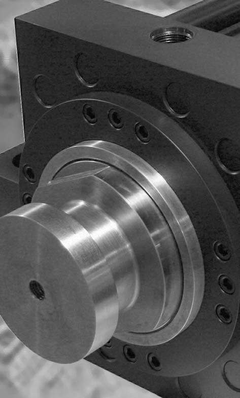
24 Technical Data Seal Kits Sensors Options Accessories Rod Lock Basic Cylinder SERIES HH WITH HYDRAULIC ROD LOCK The TRD difference... TRD s floating rod bushing design and RL Series Rod Lock = OPTIMIZED RESULTS and SUPERIOR PERFORMANCE. For rod locks to achieve the rated holding force and maximize cycle life, good alignment must be maintained between the locking mechanism and cylinder rod. With TRD s Floating Rod Bushing design and accurate rod lock alignment - superior performance and trouble-free operation are assured. Rod locks are used to hold linear cylinder loads stationary in any mounting orientation during power off condition. Units will lock in both directions to rated holding force. They are not designed to withstand rotational loads or to brake the load in dynamic applications. TRD offers each rod lock model in three different holding force, depending on available release pressure. Refer to page 23 for minimum release pressure and corresponding holding force. Load B Hydraulic PSI Exhausted, ZERO back pressure ROD LOCKED OPERATING PRESSURE Cylinder Refer to Cylinder Mount Rating Rod Lock (Low PSI) 750 to 3000 PSI HYD. Rod Lock (Med PSI) 1000 to 3000 PSI HYD. Rod Lock (High PSI) 1500 to 3000 PSI HYD. AXIAL MOVEMENT (CLAMPED) * Load Direction A.000 Load Direction B.012 Max. * Represents clearance within the rod lock unit,.000 movement due to actuation. OPERATING PRINCIPAL Load A UNCLAMPED CONDITION: When hydraulic pressure is applied to rod lock, the hydraulic pressure overcomes the spring force, moving Piston Outer Locking Housing. This movement provides clearance between the rod lock and piston rod which allows free rod movement. CLAMPING (Locked) CONDITION: When hydraulic pressure is exhausted from rod lock, extreme spring force is applied to the piston/outer lock housing which utilizes an ultra-fine tapered wedge, transferring the spring force directly to the rod. Clamping action does not move or disturb the rod, maintaining rod position during actuation. Air Vent Plug 3000 PSI (Max) Release Pressure ROD FREE MOVING Balluff Prox. Switch (Optional) OPERATING TEMPERATURE Standard Seals 20 F to 200 F (-29 C to 93 C ) Fluorocarbon Seals 0 F to 400 F (-18 C to 204 C ) ROD MATERIAL REQUIREMENTS Diameter to Nominal Diameter Hardened Shaft.0005 Minimum hard chrome Finish 6 to 10 micro-inch CLAMP SPECIFICATIONS Response Time 100 ms (Clamp); 100 ms (Un-clamp) Average Life 1,000,000 Clamp Cycles 22
25 ME5 HOW TO ORDER: SERIES HH WITH ROD LOCK HH - ME x 10 - H2C KK1 - P15 = N375 - S S S S - REQUIRED MOUNT HEAD RECTANGULAR MOUNT (1.50 to 8.00 Bore) MF2 MF5 MF6 MP1 MS2 MS3 MS4 MS7 MT1 MT2 MT4 Replacement Rod Locks can be ordered using the same methodology. Examples: RLH RLH P NFPA MOUNT (TO MOUNT CYLINDER) CAP RECTANGULAR FLANGE (1.50 to 6.00 Bore) SQUARE FLANGE, HEAD END (1.50 to 8.00 Bore) SQUARE FLANGE, CAP END (1.50 to 8.00 Bore) FIXED CAP PIVOT CLEVIS (1.50 to 8.00 Bore) SIDE LUGS (1.50 to 8.00 Bore) CENTER LINE LUGS (1.50 to 8.00 Bore) BOTTOM TAPPED HOLES (1.50 to 8.00 Bore) END LUGS (1.50 to 8.00 Bore) HEAD TRUNNION (1.50 to 8.00 Bore) CAP TRUNNION (1.50 to 8.00 Bore) INTERMEDIATE (CENTER) TRUNNION (1.50 to 8.00 Bore) See page 5 for additional cylinder How-to-Order information. ROD SIZE BORE MODEL NUMBER < MIN. RELEASE PSI < Maximum hydraulic release pressure: 3000 PSI. = Holding forces are based on dry or mineral-oil lubricated shafts. TECHNICAL DATA: ROD LOCKS = MAX HOLDING FORCE VOLUME OF OIL CM 3 IN 3 WEIGHT (LBS) RLH , RLH , RLH , RLH , RLH , RLH , RLH , RLH , RLH , RLH , RLH , RLH , RLH , RLH , RLH , RLH , RLH , RLH , RLH , RLH , RLH , RLH , RLH , RLH , ROD SIZE BORE MODEL NUMBER OPTIONS ROD LOCK READY CYLINDER RLH NO ROD LOCK INSTALLED CYLINDER WITH INSTALLED RLH=MODEL NUMBER ROD LOCK Example: RLH= Rod Lock Model Numbers RLH= < MIN. RELEASE PSI ROD SIZE BORE = MAX HOLDING FORCE RELEASE PSI VOLUME OF OIL CM 3 IN 3 OPTIONS WEIGHT (LBS) RLH , RLH , RLH , RLH , RLH , RLH , RLH , RLH , RLH , RLH , RLH , RLH , RLH , RLH , RLH , RLH , RLH , RLH , RLH , RLH , RLH , RLH , RLH , P V X Proximity Switch Ready Fluorocarbon Seals Special (Specify) Basic Cylinders Rod Lock Accessories Options Sensors Seal Kits Technical Data 23
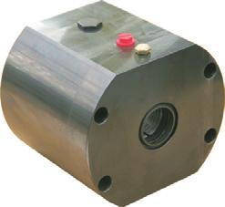
26 Technical Data Seal Kits Sensors Options Accessories Rod Lock Basic Cylinder SERIES HH WITH ROD LOCK: BASIC CYLINDER ME5 (No Mount) To be able to handle the high holding forces, the rod lock cylinder uses a ME5 full rectangle cylinder head and full rectangle bushing retainer plate to mount the rod lock unit to the cylinder. Customers need to specify an additional mount to attach cylinder in the application. Refer to pages 6 through 17 for basic cylinder dimensions not shown. < Air Vent Plug. = M12x1 port for optional proximity switch (indicates unclamped condition). ROD DIA (MM) BORE D E FH TF UF UW RL RLC RLEE RLF RLG RLJ RLP RLY ADD TO STROKE SAE SAE SAE SAE SAE SAE SAE SAE SAE SAE SAE SAE SAE SAE SAE SAE RLZB 24
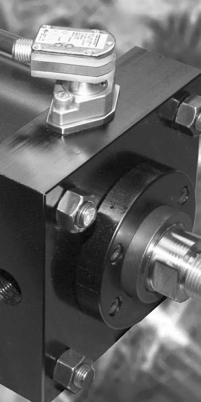
27 Rod Lock Hydraulic Circuit and Automatic Air Bleed Valve In most applications, the sample circuit in figure 1 is used to actuate the rod lock. To release (unclamp) the rod lock, the 3-way valve is energized, supplying pressure to the rod lock. In power failure modes, E-Stop, loss of hydraulic pressure, etc., pressure is removed from the rod lock- spring energized rod lock clamps the rod holding it in place. Avoid designs where the piston rod is moved while rod lock is actuated (clamped condition); piston rod and rod lock damage may occur. Do not exceed the maximum holding force of the rod lock unit. p Recommended if pressure spike occur if pressure not constant Automatic Air Bleed Valve ABV-1 All rod lock units have a very short activation stroke and quick (100ms) response. It is highly recommended that all air be removed from the rod lock unit. Trapped air at high pressure and frequent cycling can cause ignition of the air-oil mixture, causing mini explosions (dieseling) to occur- which will lead to seal failure. To avoid trapped air, an Automatic Air Bleed Valve (or similar component) should be installed between the rod lock and the oil reservoir. Locate the ABV-1 as near as possible to the rod lock, in the port with the highest elevation (see figures 2 and 3). ABV-1 Operation The Automatic Air Bleed Valve (ABV-1) opens slightly each time pressure is removed from the rod lock, allowing air to escape back to the oil resevoir. For proper operation, back pressure exceeding 30 PSI (2 bar) should be avoided between the ABV-1 and oil resevoir. Figure 1 Figure 2: Vertical Mount SIT-EMMEA [63.5mm] Air Bleeder AIR BLEED P/N: SIT-EMMEA-4 G 1/4 Part Number: ABV-1 (Order separately) Note: Use NPTF fittings to install Figure 3: Horizontal Mount Basic Cylinders Rod Lock Accessories Options Sensors Seal Kits Technical Data 25
28 Technical Data Seal Kits Sensors Options Accessories Rod Lock Basic Cylinder ROD LOCK SENSORS (For Unclamped Condition) An inductive proximity switch (with M12 x 1 thread) can be used to sense the rod lock unclamped (free moving rod) condition. (BALLUFF Model: BES S4) ELECTRICAL DATA SA Operational distance with steel 1.6 mm Maximum switching frequency 800 Hz Operating voltage V DC Supply voltage ripple 15% (Peak to Peak) Load current capacity 200 ma Protection against polarity reversal yes Short circuit protected yes Function display LED Output resistance 2.2 K + Diode + LED Ambient temperature range -25 C to 70 C (-13 F to 158 F) Temperature of switch point 4 mm / C Parallel cap to load permitted 1 mf at 24 V DC Residual voltage (unclamped) 0.8 V Voltage drop (clamped) 2.5 V Voltage rise on switching Switching hysteresis 15% Sensing distance Repeatability 5% Sensing distance Current Consumption 25 ma clamped / 12 ma unclamped PROXIMITY SENSOR INSTALLATION INSTRUCTIONS 1) Apply hydraulic pressure to rod lock (unclamped condition). 2) Assemble the proximity sensor jam nut and lock tooth washer to the proximity sensor. Thread the proximity sensor (by hand) into the M12 x 1 rod lock threaded port until it contacts the internal steel piston. 3) Back the proximity sensor out 1 full turn. While holding the proximity sensor s position, tighten the jam nut to 15 ft-lbs (do not over torque). 4) With electrical power off, connect the proximity sensor electric wiring per the diagram included with the sensor. When the electrical power is on, the proximity sensor LED should be On, indicating an unclamped condition. Slight adjustments may be necessary to set proximity sensor for proper operation. 5) Remove the hydraulic pressure to the rod lock, the proximity sensor LED should go Off, indicating the clamped conditions. ROD LOCK INSTALLATION INSTRUCTIONS SCHEMATIC Wiring Connections: PNP Normally Open 1) Using a flexible hydraulic rated hose, apply hydraulic pressure to the rod lock unit (refer to model number for specific rod lock hydraulic release pressure.) 2) With the rod lock counter-bored end facing the cylinder rod end, align rod lock to rod. Using care not to damage rod lock seals or bearings, slide the rod lock onto the rod lock til it contacts the cylinder mounting surface. Rod lock should fully contact the cylinder. 3) Remove the hydraulic pressure to the rod lock. Torque cylinder tie rod nuts a little at a time, in a clockwise rotation, finishing with the proper cylinder tie rod torque. Refer to torque charts on page 51. 4) Cycle the rod lock unit on and off several times. With pressure applied, the cylinder rod should move freely by hand. 5) If the cylinder rod does not move freely, remove the rod lock and repeat installation instructions. If the piston rod still drags, check the squareness of the rod lock to the cylinder and make adjustments as needed. WARNING! DO NOT DISASSEMBLE ROD LOCK UNIT CONTAINS HIGH SPRING FORCE THAT COULD CAUSE PERSONAL INJURY. Return to TRD Mfg. for service. 2 N/C Load View of Male Connector Pins N/O 26
29 CLEVIS BRACKET EYE BRACKET EYE ROD ROD CLEVIS SERIES HH ACCESSORIES: CLEVIS, PINS & MOUNTS PART NO MAX LOAD (TENSION) RATED IN LBS BA CB CLEVIS BRACKET DIMENSIONS CD (DIA.) CW DD E F FL L M CB / CB / CB / CB / CB / CB CB / CB / CB / PART NO MAX LOAD (TENSION) RATED IN LBS BA CB EYE BRACKET DIMENSIONS CD (DIA.) DD E F FL L M EB EB EB EB EB EB EB EB EB EB PART NO MAX LOAD (TENSION) RATED IN LBS ROD EYE DIMENSIONS A CA CB CD (DIA.) ER (RADIUS) RE /16-20 RE /2-20 RE /4-16 RE RE /4-12 RE /2-12 RE /8-12 RE /4-12 RE /2-12 RE /4-12 RE /2-12 RE PART NO MAX LOAD (TENSION) RATED IN LBS CB CD (DIA.) ROD CLEVIS DIMENSIONS CE CH CW ER (RADIUS) RC / RC / RC / RC RC / RC / RC / RC / RC / RC / RC / RC / RC KK KK L Basic Cylinders Rod Lock Accessories Options Sensors Seal Kits Technical Data 27
30 Technical Data Seal Kits Sensors Options Accessories Rod Lock Basic Cylinder WELD PLATE SERIES HH ACCESSORIES: CLEVIS, PINS & MOUNTS PIVOT PIN (INCLUDES COTTER PIN) PIVOT PIN (INCLUDES E-CLIPS) FLANGE END COUPLER PIVOT PIN DIMENSIONS MAX LOAD PART NO (TENSION) CD LP LH RATED IN LBS CP500C CP750C CP1000C CP1375C CP1750C CP2000C CP2500C CP3000C CP3500C CP4000C PIVOT PIN DIMENSIONS MAX LOAD PART NO (TENSION) CD LP LH RATED IN LBS CP500E CP750E CP1000E CP1375E CP1750E CP2000E CP2500E CP3000E CP3500E CP4000E PART NO PART NO ROD DIA. ROD DIA. WELD PLATE DIMENSIONS E F G (DIA.) FLANGE END COUPLER DIMENSIONS H I K L M WP WP / WP / WP / WP / WP / WP / WP / WP / WP / WP / WP / B C D H I J L M N P FEC FEC FEC FEC FEC FEC FEC FEC FEC FEC FEC FEC


31 SERIES HH ACCESSORIES: ALIGNMENT COUPLERS Solid Steel self-aligning piston rod couplers TRD s alignment couplers can virtually pay for themselves by eliminating the need to precisely mount cylinders in your applications. Our couplers prevent binding and erratic movement that misalignment causes, extending the bearing and seal life of your cylinders. Proper use of alignment couplers will allow cylinders to stroke in the shortest time possible, increasing production! Benefits Rod alignment couplers eliminate expensive machining for mounting fixed or rigid cylinders on guided or slide applications. Simplifies alignment problems in the field. Design Tips Alignment couplers can be exposed to high stresses that are not apparent in an application. Always use the largest thread size practical in your application. (see chart for maximum pull yields) Use jam nut to lock coupler to rod when used with full diameter threads. (example: 1.00 thread on 1.00 rod) Large thread sizes can be pinned in tough duty applications, eliminating unwanted loosening of coupler from rod. Always use the smallest pin possible to avoid weakening the piston rod thread. AC SERIES ALIGNMENT COUPLER DIMENSIONS PART NO. A B C D E F G H H HEX J MAX PULL AT YIELD AC ,000 AC ,300 AC ,300 AC ,000 AC ,000 AC ,000 AC ,000 AC ,000 AC ,000 AC ,000 AC ,000 AC ,000 AC ,000 AC ,000 AC ,000 AC ,000 AC ,000 S AC ,000 AC P H 344,000 AC A O 536,000 AC N L 536,000 AC N E 536,000 AC ,000 E S AC ,000 AC R 776,000 *Please specify AC or ACH coupler when ordering: i.e.: AC750 (Std. Coupler) or ACH750 (Hex Coupler). *Spanner holes are used on AC2250 and larger, (2) 1/2 dia. holes, 1/2 deep, 180 apart (each end). 29 ACH SERIES Standard AC Coupler AC250 - AC5000 ACH Coupler ACH250 - ACH1250 Recommended maximum stroke for cylinders with alignment couplers in horizontal applications BORE MAXIMUM STROKE Basic Cylinders Rod Lock Accessories Options Sensors Seal Kits Technical Data

32 Technical Data Seal Kits Sensors Options Accessories Rod Lock Basic Cylinder Index To Standard Options: PAGE A= - Extended Piston Rod Thread AS - Adjustable Stroke (Retract) C= - Extended Piston Rod CS - Center Support C or H - Cushions EK - Extended Key Plate EN - Electroless Nickel Plating HP - High Impact Piston (nut on piston rod) KKX - Non-Standard Rod Threads Uncommon Options: PAGE AS3POS - Adjustable Mid Stroke (3 Position Cyl.) DAS - Double Rod Adjustable Stroke (Extend) Spherical Bearing (cap pivot mount) Extra Wide Multiple Wear Bands Hollow Piston Rods Rod Boots A= Extended Piston Rod Thread A= refers to the length of piston rod thread. Shorter than standard lengths can be furnished at no charge. Longer than standard lengths can be furnished at a nominal price adder. Special length threads do not delay orders! Note: Maximum thread length is double the standard A length. C= is commonly referred to as Piston Rod Extension. Piston rods can be extended to any length up to 120 total piston rod length, including stroke portion. Cylinders with long C lengths can be mounted away from obstacles or outside hazardous environments. CS Center Supports Center Supports are recommended for long stroke cylinders to support tube and prevent the tie rods from sagging. Properly supported cylinders will eliminate premature cylinder wear and eliminate tie rod vibration. Center Supports can include MS4 or MS2 mounts. Contact TRD for more information. SERIES HH BASIC OPTIONS PAGE Multiple Mounts NR - Non-Rotating Port Options (BSPP, BSPT, NPTF, SAE, Flange) RBB - Rod Bushing - Bronze (Ductile Iron is Standard).. 33 RLH - Rod Lock SSR - Stainless Steel Piston Rod Seals (Piston, Rod, Tube, Wiper) ST - Stop Tube XX - Special Modifications PAGE Paint and Other Special Finishes Back To Back Cylinders Position Cylinders Tandem Cylinders Head & Cap Air Bleeds Rod Gland Drain AS C= Extended Piston Rod TIP Adjustable Stroke (Retract) Consists of a threaded rod in the cylinder cap, non-removable. Provides an adjustable positive stop on the cylinder retract. To order, specify AS and length of adjustment (Example: AS=3 ) ADJUSTABLE STROKE BORE MAX. AS 1.50 Up to 8 inch Up to 6 inch Up to 5 inch 8.00 Up to 4 inch Piston rods can be made to any length up to 120 inches. Rods can be easily extended to move a cylinder to a more accessible location, or away from a less desirable environment. Be sure to check piston rod column strength charts to properly size the rod and prevent buckling. Extended piston rods do not delay delivery. CENTER SUPPORT RECOMMENDATIONS BORE ONE SUPPORT TWO SUPPORTS 1.50 STROKES OVER 44 INCHES STROKES OVER 89 INCHES 2.00 STROKES OVER 74 INCHES STROKES OVER 99 INCHES 2.50 STROKES OVER 84 INCHES NOT STROKES OVER 99 INCHES REQUIRED 30
33 Cushions TRD s cushion design features industry proven technology and ultra fine adjustment needles for perfect deceleration and long life. Cushion adjustment needle positions need to be specified. Example: H2C6 EK Extended Key Plate or thrust key is made from a full square bushing retainer plate. The key is designed to fit in a milled slot on the equipment to prevent the cylinder from shifting. An additional mount needs to be specified to secure cylinder. Available bore sizes: 1.5 to 8 Bore EN Extended Key Plate Electroless Nickel SERIES HH BASIC OPTIONS EN or Electroless Nickel plating was invented in 1946, and has gained worldwide commercial usage since Common usages include aircraft landing gear, automotive brake cylinder and components, fuel injector parts, gas turbine parts, spray nozzles for chemical applications and many electronic devises including hard drives. The properties of Electroless Nickel contribute to the multitude of uses. The coating provides an attractive finish, while exhibiting high abrasion and corrosion resistance. It s ability to uniformly coat blind holes, threads, internal surfaces and sharp edges contributes to its effectiveness. It has a very high bonding strength to the base metal (100, ,000 PSI), so much so that gas turbines use electroless nickel plating as a base to braze broken blades to. COMMON USAGES: CUSHION LOCATIONS HEAD CUSHION CAP CUSHION H1 C5 H2 C6 H3 C7 H4 C8 FOOD PROCESSING EN plating has been used to handle such diverse products as sodium hydroxide, food grade acids and fish oils. Excellent resistance to mild sanitizing caustics, chlorine, and chlorides in general. The natural smooth finish ensures cleanliness in food processing equipment. PETROLEUM AND CHEMICAL The petroleum and chemical industry are large users of electroless nickel plating for corrosion protection. Design tip: Submit the list of chemicals and concentration levels to TRD for evaluation and recommendations. In some instances, Stainless Steel cylinders provide the best value and long cylinder life. MEDICAL AND PHARMACEUTICAL The medical industry uses EN plated cylinders in clean-rooms, on equipment used to make plasma or IV bags, since it is critical that cylinder components need to be sterilized and particle flake free. The pharmaceutical industry typically can be harsh on equipment, even abusive-but the equipment must remain completely reliable. EN cylinders provide the most reliable and cost effective choice. HP HP Option Heavy-Duty hex nut to retain piston to piston rod. UNAVAILABLE CUSHION LOCATIONS BY MOUNT MOUNT HEAD CAP CUSHION CUSHION ME5 H2, H4 ME6 C6, C8 MS3 H2, H4 C6, C8 MT1 H2, H4 MT2 C6, C8 EN CYLINDER SPECIFICATIONS EN PLATED PARTS: Tube, Head, Cap, Bushing Retainer, Mounts, Tie Rods and Nuts OTHER COMPONENTS: 303/304 Stainless Steel: Rod Bushing Retainer Screws, Piston Rod (hard chrome plated), SAE 660 Bronze Rod Bushing EN PLATING SPECIFICATIONS: HIGH PHOSPHORUS (highest corrosion resistant Electroless Nickel plating available) COMPOSITION: 87-90% Nickel, 10-13% Phosphorus HARDNESS: Rc THICKNESS: LUBRICITY: Excellent (Similar to chrome) COEFFICENT OF FRICTION: Low FINISH: Bright and very smooth MAX. STROKE = 50 Refer to page 17 for all dimensions and details Other types of EN plating are available. Contact TRD with your specifications for a prompt quote. NOTE: Due to the lower yield strength, Stainless Steel piston rods should be sized for proper column strength. Basic Cylinders Rod Lock Accessories Options Sensors Seal Kits Technical Data 31

34 Technical Data Seal Kits Sensors Options Accessories Rod Lock Basic Cylinder KKX Non-Standard Rod Threads SERIES HH BASIC OPTIONS Cylinders piston rods can be furnished with non-standard rod threads. Ordering Example: HH - MF1-150 X KKX UNC - P15 - SSSS MULTIPLE MOUNTS Cylinders can be furnished with a wide selection of multiple mounts. Ordering Example: HH - MF1 - MS2-250 X KK1 - P15 - SSSS NR Benefits Two internal guide rods throughout stroke High repeatability at each end of stroke (+/- 1 degree) All external dimensions are the same as standard cylinder (no additional length or width required) Standard Diameter Guide Rod Seals & Bronze Bearings for long life and reliable operation Available in Double Rod End Models Advantages Non-Rotating (NFPA) Cylinders Eliminates the need for external guide shafts in many positioning applications Guide rods are internal, self-cleaning, not subjected to harsh cleaners Compact design saves space, no larger than standard NFPA cylinders! Durable, self-contained construction Application Possibilities: Custom Rod Thread Size Add additional mount to part number AVAILABLE BORE SIZES WITH NR GUIDE ROD SIZES AND MAX. STROKE BORE ROD DIA. MAXIMUM CUSHIONS (MM) STROKE Cap Only Available Available Available 40 Note: External guide rod models are available with rectangular head and cap. Contact TRD for more information. 32
 threads have the same taper as American NPT tapered threads, but use a 55 Whitworth")
35 PORT OPTIONS Cylinders can be furnished with NPTF or SAE O-Ring Boss (SAEJ514) ports at no-charge. Cylinders can be furnished with BSPP, BSPT, or SAE Flange Ports for additional cost. RBB Bronze Rod Bushings SERIES HH BASIC OPTIONS BSPT British Standard Pipe Taper British Standard Pipe Taper (BSPT) threads have the same taper as American NPT tapered threads, but use a 55 Whitworth thread form and different diameters. (Not interchangeable with NPT) BSPP British Standard Pipe Parallel British Standard Pipe Parallel (BSPP), also referred to as BSP Straight Thread. (Not interchangeable with NPT) SAE FLANGE PORT Cylinders can be furnished with Bronze (RBB) Rod Bushings (standard material: 150,000 PSI ductile iron, PTFE coated) RLH Rod Lock Cylinders can be furnished with Hydraulic Rod Locks. Refer to pages for complete specifications. SSR 17-4 Stainless Steel Hard Chrome Plated Piston Rod 100,000 min. yield (rods up to 5.00) 75,000 min. yield (5.500 rod) Cylinders can be furnished with Hard Chrome plated Stainless Steel Piston Rods. Due to lower yield strength, stainless steel piston rods should be sized for proper column strength. SEALS PISTON SEAL S STANDARD (Carboxilated) C Cast-Ring E EP T PTFE V Fluorocarbon C The HH Series allows for the use of different types of seal design and material compounds in every area, for maximum flexibility and performance. Cast Iron Piston Rings Temperature Range: Compatible with: Virtually all fluids MS How to Order Seals S S S S ROD SEAL S STANDARD (Polyurethane) E EP V Fluorocarbon Metallic Rod Scraper TUBE SEAL S STANDARD (Buna) E EP V Fluorocarbon ROD WIPER S STANDARD (Flocked Nitrile) M Metallic Scraper T PTFE V Fluorocarbon Aggressively scrapes the piston rod, removing foreign material such as spatter, sprays and powders. (Brass contruction) S Standard Seals Piston: Carboxilated Nitrile Tube Seals: Buna Temperature Rating: -20 F to 200 F (-29 C to 93 C) Compatible with: Mineral based hydraulic fluids E Ethylene Propylene Rod Seal: Polyurethane Rod Wiper: Flocked Nitrile Temperature Rating: -50 F to 300 F (-45 C to 149 C) Compatible with: Most Phosphate Ester (Skydrol 500 and 7000, type 2) fluids T Glass Filled PTFE Temperature Rating: -100 F to 400 F (-73 C to 204 C) Compatible with: All Hydraulic fluids, and almost any fluid. Contact TRD for specific compatibility. V Fluorocarbon Temperature Rating: 0 F to 300 F (-18 C to 149 C) (Up to 400 F with reduced service life) Compatible with: Some Phosphate Ester (Houghto-Safe 1000, 1120; Pyrogard 42, 43, 53, 55) fluids; mineral based petroleum, halogenated hydrocarbons, silicate ester and diester fluids XX Special Non-standard seals can be furnished. Contact TRD for more information. Contact TRD for more information. Basic Cylinders Rod Lock Accessories Options Sensors Seal Kits Technical Data 33
36 Technical Data Seal Kits Sensors Options Accessories Rod Lock Basic Cylinder ST Stop Tubes are designed to reduce the piston rod bushing stress to within the designed range of the bearing material. This will insure proper cylinder performance, in any given application. Stop Tubes lower the cylinder bearing stress by adding length to the piston, which increases the overall length of the cylinder. (Note: TRD uses a double piston design when possible.) Stop Tube Selection To determine the proper amount of stop tube for your application, you must first find the value of D, which represents the stroke, adjusted for mounting condition. Each mounting condition creates different levels of bushing stress, which have direct impact on the amount of stop tube required. (See Chart 1) Once the value of D is known, refer to Chart 2 for the recommended amount of stop tube. To order a Stop Tube: Add the stop tube prefix ST= and the stop tube length to the cylinder model number. Add ES after the cylinder stroke to indicate that the stroke is the effective stroke. Example: HH-MS X 42ES-100-KK2- P15=N375-SSSS-ST=2 SERIES HH BASIC OPTIONS Stop Tube and Rod Size Selection Refer to page 35 for Rod Size Selection Chart 34
37 Piston Rod Size Selection SERIES HH BASIC OPTIONS Standard rod sizes are usually suitable for shorter stroke applications at lower hydraulic pressures. With high thrust force or long stroke applications, you must check the column strength of the rod in the mounting style to determine the proper rod diameter size. 1. Determine the total axial thrust by multiplying the bore area size (in inches) by the operating pressure (in PSI). Refer to page 51 for cylinder force chart. 2. From page 34, determine the value of D for the application. 3. Find the value of D in the chart below. Follow the value of D vertically on the graph until it intersects with the Axial Thrust value of the cylinder. The intersection of these two values will fall within one of the shaded areas representing the piston rod diameter size required for the application. Basic Cylinders Rod Lock Accessories Options Sensors Seal Kits Technical Data 35
 Double piston design allows for adjustment of the mid stroke position.")


 Optional Paint: Black Epoxy Paint (suitable for indoor use only.")
 Consists of a double rod end cylinder and an adjustable stop collar.")

38 Technical Data Seal Kits Sensors Options Accessories Rod Lock Basic Cylinder AS3POS SERIES HH UNCOMMON OPTIONS Adjustable Mid Stroke (3 Position Cyl.) Double piston design allows for adjustment of the mid stroke position. Three ported cylinder with adjustable stop collar. Contact TRD with your specifications. PORT A PORT B PORT C SPHERICAL PIVOT BEARINGS Spherical pivot bearing mounts can be furnished as a weldment. MP4SP Spherical Mount. Contact TRD with your specifications. HOLLOW PISTON RODS This cylinder shows a multitude of options: Double Oversize Piston Rod, Gun- Drilled, Double Rod End with rod extension, special female rod thread, and special side drilled angle hole in piston rod. Contact TRD for rod column strength limitations and more information. SPECIAL FINISHES DAS Standard Finish: Black Urethane Paint (suitable for indoor or outdoor use.) Optional Paint: Black Epoxy Paint (suitable for indoor use only.) Additional Paint Choices: TRD can provide paint in any color or type. Contact TRD with your specifications. Double Rod Adjustable Stroke (Extend) Consists of a double rod end cylinder and an adjustable stop collar. Used to adjust the extend cylinder stroke. Contact TRD with your specifications. EXTRA WIDE MULTIPLE WEAR BANDS 8 Piston with two 1 wide wear bands shown. ROD BOOTS Additional Finishes: TRD can provide special finishes, i.e., Nutride Plate Contact TRD with your specifications we would be pleased to provide a quote! Heavy Chrome Plated Piston Rods. Contact TRD for more information. Rod Boots are common in dirty environments a standard spec for many applications. (Note: Rod Boots add length to cylinder rod extension contact TRD for specifications) 36


39 BTB Back to Back cylinders consist of two individual cylinders built as one unit. These cylinders can act as a 4 position cylinder. Contact TRD for more information. 3P SERIES HH UNCOMMON OPTIONS Back-To-Back Cylinders Three-Position Cylinder You can create a 3-Position cylinder from two of the same bore size cylinders. 3-Position cylinders consist of multiple cylinders built as one unit having ONE exposed working rod end, capable of delivering 3 rod positions. 3-POSITION BENEFITS: 3-POSITIONS IN ONE CYLINDER One cylinder produces three different rod end positions. By varying stroke lengths, a multitude of positions can be created. SIMPLIFIES MACHINE DESIGNS Eliminates the need for an additional cylinder to create a third position. 3-Position cylinders reduce space and the cost to mount multiple cylinders. Note: Piston rods are not connected. Contact TRD for more information. TM Tandem Cylinders You can tandem different cylinders together to create unlimited design possibilities. Note: Piston rods are connected. Contact TRD for more information. HEAD & CAP AIR BLEEDS Air bleeds can be provided at either or both ends of the cylinder. Air bleeds should be located at the highest point in the cylinder for maximum effectiveness. The location needs to be specified, similar to port locations. Contact TRD for more information. ROD DRAIN When no oil leakage can be tolerated, a rod bushing Drain port can be provided. Since there isn t any pressure in the drain line, clear tubing can offer a visual inspection of any leakage. A constant leak indicates that the rod seal is worn and needs to be replaced. Contact TRD for more information. 3-POSITION CYLINDERS HOW THEY WORK Basic Cylinders Rod Lock Accessories Options Sensors Seal Kits Technical Data 37


40 Technical Data Seal Kits Sensors Options Accessories Rod Lock Basic Cylinder Flexible Solutions for an Often Inflexible World Balluff s new Strokemaster cylinder-piston sensors provide precision end-ofstroke sensing for hydraulic cylinders. It also eliminates post-installation cable management problems with 304 of rotational freedom on the connector. Strokemaster sensors allow infinately adjustable and lockable cable positioning anytime after mounting to the cylinder. Without breaking the seal, Strokemaster enables quicker installation of the sensor and neat cable runs. A high-pressure, inductive proximity switch, the Strokemaster sensor provides a 2mm (0.8 ) sensing range to pick up the spud of hydraulic cylinders and indicate fully retracted or extended position. It mounts with just two screws, and seals with an O-ring. Withstanding cylinder pressures to 3000 psi (207 BAR), the embeddable design keeps most of the switch protected within the cylinder, with only a 0.62 (16mm) high housing exposed outside. The rotating housing can be locked in the desired position with either one of two set screws. SERIES: BALLUFF INDUCTIVE SENSORS Strokemaster sensors are available in 3-wire DC and 2- wire AC/DC versions, both with mini or micro connectors. Switching frequency is 50 Hz in the AC/DC versions. All units are weld-field immune and short-circuit and reverse polarity protected. They fit all popular cylinder designs, with standard probe lengths of (26mm mm), along with available custom probe lengths and spacers. Probes are made of stainless steel with a ceramic face. Both DC and AC/DC sensors have all metal housings. Strokemaster is CE-certified, and its housing is sealed to IP67 requirements. Inductive Sensors 38
 versions Easy installation - sensor mounts to cylinder with (2) fasteners Sealed directly at flange,")


41 Features/Advantages Inductive cylinder switch for piston position feedback in cylinders. Magnetic field immune, for use with welding equipment Available in DC or all current (AC/DC) versions Easy installation - sensor mounts to cylinder with (2) fasteners Sealed directly at flange, connector can be oriented after installation Various lengths available for different cylinder sizes Bolt sensor to cylinder. Position cable to desired orientation (even over mounting bolts). Lock chosen position with one or both of the two integral set screws. Refer to page 41 for available cable connector sets. SERIES: BALLUFF INDUCTION SENSORS DC INDUCTIVE SENSORS PNP Normally-open Rated operational voltage Ue Supply voltage UB Voltage drop Ud at le Rated insulation voltage Ui Rated operational current le No-load supply current lr d./und. Off-state current lr Protected against polarity reversal Short circuit/overload protected Load capacitance Repeat accuracy R Ambient temperature range Ta Frequency of operating cycles f Utilization categories Function/Operating voltage indication Degree of protection per IEC 529 Housing material Material of sensing face Connection Recommended connector Approvals BES S 295-S 4 24 V DC V DC < 2.5 V 75 V DC 200 ma < 18 ma/< 10 ma < 80 µa yes yes/yes < 1.0 µf < 5 % C 10 Hz DC 13 yes/yes IP 67/connector IP 65 stainless steel/aluminum ceramic connector Micro M12DC UL, cul < TRD will supply the correct length probe and spacer combination (if req d.) for each cylinder. Using the combination of std. probe lengths & spacers will give the appropriate.030 gap between sensor and cylinder spud. The spacers supplied have the same base profile as the sensor. (Material: Stainless Steel) HOW TO ORDER CYLINDERS WITH BALLUFF SENSORS: STANDARD LOCATIONS: Ports at 1 and 5 Cushions at 2 and 6 Sensors at 4 and 8 (Specify non-standard locations) (Micro M12DC Connector) Note: TRD will include the STROKEMASTER probe length on your order, and any sensor spacers required. (Example: HH-MS KK1-N500- BES S4 /1.025-S21 (Head) -BES S4 /1.75-S21 (Cap)- Sensors at 4 & 8. < Cylinder Model Number á SENSOR MODEL (HEAD) á SENSOR MODEL (CAP) á (Include ALL Sensor positions) á How To Order: HH-MS KK1-N500 -BES S 295-S4 (Head) -BES S 295-S4 (Cap) -Sensors at 4 & 8 Basic Cylinders Rod Lock Accessories Options Sensors Seal Kits Technical Data 39
42 Technical Data Seal Kits Sensors Options Accessories Rod Lock Basic Cylinder Normally-open Rated operational voltage Ue Supply voltage UB Voltage drop Ud at le Rated insulation voltage Ui Rated operational current le Minimum operational current lm Off-state current lr Inrush current lk (t = 20 ms) Protected against polarity reversal Short circuit protected Repeat accuracy R Ambient temperature range Ta Frequency of operating cycles f Utilization categories Function/Operating voltage indication Degree of protection per IEC 529 Insulation class Housing material Material of sensing face Connection Recommended connector Approvals Refer to page 41 for available cable connector sets. SERIES: BALLUFF INDUCTION SENSORS AC/DC INDUCTIVE SENSORS < BES S 2-S V DC V AC/DC < 6 V 250 V AC 500 ma 5 ma < V AC 3 A max./1 Hz yes yes < 5 % C < 50 Hz AC 140/DC 13 yes/yes IP 67 1 stainless steel/nickel plated brass ceramic connector Micro AC UL, cul < BES S 2-S5 110 V DC V AC/DC < 6 V 250 V AC 500 ma 5 ma < V AC 3 A max./1 Hz yes yes < 5 % C < 50 Hz AC 140/DC 13 yes/yes IP 67 1 stainless steel/nickel plated brass ceramic connector Mini UL, cul < TRD will supply the correct length probe and spacer combination (if req d.) for each cylinder. Using the combination of std. probe lengths & spacers will give the appropriate.030 gap between sensor and cylinder spud. The spacers supplied have the same base profile as the sensor. (Material: Stainless Steel) HOW TO ORDER CYLINDERS WITH BALLUFF SENSORS: STANDARD LOCATIONS: Ports at 1 and 5 Cushions at 2 and 6 Sensors at 4 and 8 (Specify non-standard locations) Cylinder Model Number á SENSOR MODEL (HEAD) á SENSOR MODEL (CAP) á (Include ALL Sensor positions) á How To Order: HH-MS KK1-N500 -BES S 2-S21 (Head) -BES S 2-S21 (Cap) -Sensors at 4 & 8 Note: TRD will include the STROKEMASTER probe length on your order, and any sensor spacers required. (Example: HH-MS KK1-N500- BES S 2 /1.025-S21 (Head) -BES S 2 /1.75-S21 (Cap)- Sensors at 4 & 8. 40
43 Connector Style Configuration 3 Pole Mini Connectors Voltage Rating Amperage Wire Gauge Jacket Coupling Nut Protection Ambient Operating Temp. UL Listed CSA Certified 3-5 Pole Mini Mini Size A Straight Female SERIES: BALLUFF INDUCTION SENSORS CABLE CONNECTORS ORDER NUMBER C05 AE1 00 * Y V AC/DC 10A 16 AWG PVC Black Epoxy Coated Zinc IP68 / NEMA 6P F (-21 to 105 C) Yes Yes * Insert V = PVC Cable T = TPE Cable For 3 pole versions only Micro AC.50 x 20 UNF Connectors Connector Style Configuration Ordering Code 3 Pin Dual Keyway 4 Pin Dual Keyway Voltage Rating Amperage Wire Gauge Jacket Coupling Nut O-Ring Overmold Head Protection Ambient Operating Temp. UL Listed CSA Certified Note: 15 ft cable is standard (other lengths available - contact factory) Refer to Balluff Catalog for additional cable connectors. Micro AC.50 x 20 UNF 3 Pin Dual Keyway Straight Female ORDER NUMBER C21 AE3 00 * Y 150F 250 V AC/DC 4A 22 AWG Yellow PVC or TPE Black Epoxy Coated Zinc Viton TPE IP68 / NEMA 6P F (-21 to 105 C) Yes Yes * Insert V = PVC Cable T = TPE Cable For 3 pole versions only Connector Style Configuration Micro M12 DC Connectors Note 2 Wire DC 2 Wire Normally Open Normally Closed 3 Wire DC 3 Wire Normally Open 1,2,3 3 Wire Normally Open PNP w/led 3 Wire Normally Open NPN w/led 3 Wire Normally Closed 1,2,3 3 Wire Normally Closed PNP w/led 3 Wire Normally Closed NPN w/led 4 Wire DC (NO/NC) 4 Wire 1,2,3 4 Wire PNP w/led 1,3 4 Wire NPN w/led 1,3 5 Wire DC (NO/NC with Ground) 5 Wire Voltage Rating Amperage Wire Gauge Jacket Coupling Nut *Optional Stainless Steel Protection Ambient Operating Temp. UL Listed CSA Certified Note: 5 meter cable is standard (other lengths available - contact factory) Note: Micro M12 DC Single Keyway Straight Female ORDER NUMBER C04 AEA 00 * Y 050M C04 AEB 00 * Y 050M C04 AEC 00 * Y 050M C04 AEH 00 * Y 050M C04 AEK 00 * Y 050M C04 AED 00 * Y 050M C04 AEI 00 * Y 050M C04 AEJ 00 * Y 050M C04 AEL 00 * Y 050M C04 AEM 00 * Y 050M C04 AEN 00 * Y 050M C04 AEQ 00 * Y 050M V DC 4 Amps 22 AWG Yellow PVC or TPE Black Epoxy Coated Zinc *Stainless Type 303 IP68 / NEMA 6P F (-21 to 105 C) Yes Yes * Insert V = PVC Cable T = TPE Cable For 3 pole versions only 1 Add B = Braided 80% Metallic Braid, i.e. 050 MB 2 Add S = S-Shielded 360 Degree Shield through Coupling Nut, i.e. 050 MS 3 Stainless Steel Couple Nut: Change E to S, i.e. C04ASC00TY050M Basic Cylinders Rod Lock Accessories Options Sensors Seal Kits Technical Data 41


44 Technical Data Seal Kits Sensors Options Accessories Rod Lock Basic Cylinder The waveguide consists of a special nickel-iron alloy with 0.7 mm O.D. and 0.5 mm I.D. A copper conductor is introduced through the length of this tube. The start of measurement is initiated by a short current pulse. This current generates a circular magnetic field which rotates around the waveguide. A permanent magnet at the point of measurement is used as the marker element, whose lines of field run at right angles to the electromagnetic field. In the area on the waveguide where the two fields intersect, a magnetostrictive effect causes Balluff has the right transducer for any application! Rod styles Profile styles Tubular styles Embeddable style Explosion-proof style BALLUFF TRANSDUCERS Enhanced Magnetostrictive Technology Sensor Output Options Analog an elastic deformation of the waveguide, which propagates along the waveguide in both directions in the form of a mechanical wave. The mechanical wave is converted to an electrical signal by the signal converter. The propagation time of the mechanical wave is determined by the position of the permanent magnet and can be determined to resolutions down to 5 µm. Rod Style Z.75 x 16 UNF threads Pressure rated to 8700 PSI for use in hydraulic cylinders Replaceable electronics head Analog signal adjustable in field 42 Rugged, Compact Rod Style W Rugged all stainless steel housing Designed for demanding applications Eliminates the need for protective cover UNF threads Pressure rated to 8700 PSI Compact, Bolt-in Rod Style K Rugged all stainless steel housing Bolt in design Pressure rated to 8700 PSI Eliminates the need for protective cover V and V V and V V and V ma or ma ma or ma Digital Start/Stop, RS422 Pulse-Width Modulated, RS422 PWM (w/ recirculations), RS422 Specialized Synchronous Serial Interface* CANopen Profibus DP Quadrature Resolution 0.1 mv (analog) 0.2 µa (analog) 16 bit (analog) Controller-dependent (Start/Stop & PWM) 1,2,3,5,10 µm selectable (Quadrature output) 1,5,10,20,40 µm selectable (SSI output) 5 µm increments selectable (CANopen & Profibus) 10 µm Stroke Length Active measurement area: 2 to (Consult factory for longer lengths) Wiring Options Quick disconnect Cable-out Operating Voltage 24 V DC (±20%) ±15 V DC (±2%) *(24 or 25 bit binary or gray code)

 Complete BALLUFF MICROPULSE TM Transducer information is available in")
 for information and cylinder design assistance.")
45 TRD will build your cylinder with the proper magnet, spacer plates (if required), drilling and tapping, intermediate supports (if required) and furnish the transducer as a complete unit. All cylinder/transducer assemblies are 100% tested at TRD before shipping. INTERNAL MODELS (BALLUFF Z, W, K SERIES) Not available on MP1 and MP2 Mounts 1.50 to 8 Bores Gun-drilled piston rod (Requires 1 piston rod or larger) Complete BALLUFF MICROPULSE TM Transducer information is available in catalog form or electronic PDF downloads. Visit Other Balluff models are available. Call TRD Mfg. ( ) for information and cylinder design assistance. BALLUFF TRANSDUCERS Balluff Magnet (Installed on piston) May require additional cap length SERIES Z SHOWN Basic Cylinders Rod Lock Accessories Options Sensors Seal Kits Technical Data 43

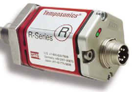
46 Technical Data Seal Kits Sensors Options Accessories Rod Lock Basic Cylinder Technology at its best MTS Temposonics TRANSDUCERS TRD will provide hydraulic cylinders built to your specifications and can incorporate MTS Temposonics Transducers in a wide variety of models. Visit for detailed product information or call TRD for more information. The best linear-position sensors provide absolute position measurement giving higher productivity and greater safety for machine and automation devices. MTS linear-position sensors outperform the competition, deliver accuracy and reliability under the most difficult conditions, providing excellent value for our customers. Our success is a result of 30 years of technology leadership, vertically integrated manufacturing processes and unsurpassed levels of customer support. MTS Sensors was the first to realize the promising advantages for linear-position measurement contained in the magnetostrictive measuring principle developed by J. Tellermann. Tellerman s original design was used to develop Temposonics brand sensors: the first magnetostrictive position sensors, a technology that guarantees precision and reliability without equal. 44 MAGNETOSTRICTIVE PRINCIPLE Magnetostriction - how it works The heart of MTS sensors is the ferromagnetic measuring element, also known as the waveguide, and a movable position magnet that generates a direct-axis magnetic field in the waveguide. When a current or interrogation pulse passes through the waveguide, a second magnetic field is created radially around the waveguide. The interaction between the magnetic field in the waveguide and the magnetic field produced by the position magnet generates a strain pulse which travels at a constant ultrasonic speed from its point of generation, the measurement point, to the end of the waveguide where it is detected by the sensor electronics. The position of the magnet is determined with high precision and speed by accurately measuring the time elapsed between the application of the interrogation pulse and the arrival of the resulting strain pulse with a high speed counter. Using the elapsed time to determine position of the permanent magnet provides an absolute position reading that never needs recalibration or re-homing after a power loss. Non-contact sensing eliminates wear, and guarantees the best durability and output repeatability. With our extensive know-how of ferromagnetic materials, magnetic effects and ultrasonic processes, MTS remains unrivaled in performance standards for non-contacting position measurement of the highest precision.
47 R-SERIES A smart sensor for fast, high precision, and synchronized position control applications. H STYLE Hydraulic/pneumatic sensor housing with integral electronics P STYLE Aluminum extrusion Profile sensor housing with integral electronics F STYLE Flexible sensing element housing with integral electronics Voltage 0 to +10V, +10 to 0V -10 to +10V, +10 to -10V (1) Voltage 0 to +10V, +10 to 0V -10 to +10V, +10 to -10V (1) Voltage 0 to +10V, +10 to 0V -10 to +10V, +10 to -10V (1) Current 0 or 4 to 20 ma, 20 to 4 or 0 ma Current 0 or 4 to 20 ma, 20 to 4 or 0 ma Current 0 or 4 to 20 ma, 20 to 4 or 0 ma DIRE CT SENSOR OUTPUTS SSI, Synchronous Serial Interface, (absolute encoder format) SSI, Synchronous Serial Interface, (absolute encoder format) SSI, Synchronous Serial Interface, (absolute encoder format) Fieldbus - CANbus (2), DeviceNet, Profibus DP Fieldbus - CANbus (2), DeviceNet, Profibus DP Fieldbus - CANbus (2), DeviceNet, Profibus DP STROKE LENGTH 50 to 7,620 mm (2 to 300 in.) 50 to 5,080 mm (2 to 200 in.) 250 to 10,060 mm (10 to 396 in.) (3) RESOLUTION 16 bit, as low as 0.01 mm ( in.) (Analog) as low as 0.002mm ( in.) (Digital) (5) 16 bit, as low as 0.01 mm ( in.) (Analog) as low as 0.002mm ( in.) (Digital) (5) 16 bit, as low as 0.01 mm ( in.) (Analog) as low as 0.002mm ( in.) (Digital) (5) Position / Displacement Position / Displacement Position / Displacement MEASUREMENT FEATURES Velocity Velocity Velocity Multiple magnets to 15 Multiple magnets to 15 Multiple magnets to 15 Analog Zero and Span Scale Adjustment Analog Zero and Span Scale Adjustment Analog Zero and Span Scale Adjustment EXTERNAL INTERFACES (1) Additional output ranges available. (2) Includes CANOpen and MTS multiple-magnet position, velocity and programmable limit switch output. (3) Consult factory for stroke lengths greater than 10,060 mm (396 in.). (4) ER stroke length range is 75 to 1,500 mm (3 to 60 in.). Articulated or unsupported sensor applications (e.g. using dual rod ends), must be limited to a maximum of 750 mm (30 in.) stroke length. (5) R-Series SSI available with 0.001mm ( in.) resolution. (6) Analog (Voltage or Current) resolution restricted by output ripple. Hydraulic/pneumatic H Style Sensing element pressure housing threads into standard size port on cylinder endcap. Industry standard for position feedback in fluid power cylinders. Convenient sensor cartridge field replacement without need to break oil seal. High pressure flange and isolation tube (5000 psi static, 10,000 psi spike). Profile P Style Extruded aluminum housing designed for convenient machine surface mounting. Ideal for precision sensing external to fluid power cylinders. Guided or floating position magnets Single or multiple magnet operation. 45
 P STYLE Aluminum extrusion Profile sensor housing with integral")


 Digital Pulse 50 to 7,620 mm (2 to 300 in.) Voltage or Current 50 to 2,540 mm (2 to 100 in.) Digital Pulse 50 to 5,080 mm (2 to 200 in.) 50 to 1,525 mm (2 to 60 in.) 75 to 1,525 mm (3 to 60 in.")
 Infinite (6) Infinite (6) Infinite (6) Infinite (6) Controller Dependent (Digital Pulse) Controller Dependent (Digital Pulse) Controller Dependent (Digital Pulse) Controller Dependent")
48 G-SERIES Programmable sensors with built in diagnostics. H STYLE Hydraulic/pneumatic sensor housing with integral electronics Voltage 0 to +10V, +10 to 0V -10 to +10V, +10 to -10V (1) P STYLE Aluminum extrusion Profile sensor housing with integral electronics Voltage 0 to +10V, +10 to 0V -10 to +10V, +10 to -10V (1) P STYLE Aluminum extrusion profile sensor housing with integral electronics E-SERIES Sensors designed for applications requiring simple and economical position feedback. R STYLE Profile sensors with Rod and Cylinder actuation and integral electronics EP2 STYLE Aluminum extrusion Profile sensor housing with integral electronics Voltage 0 to +10V, +10 to 0V Voltage 0 to +10V, +10 to 0V Voltage 0 to +10V EASY FLIP OUT PAGE FOR REFERENCE Current 0 or 4 to 20 ma, 20 to 4 or 0 ma Current 0 or 4 to 20 ma, 20 to 4 or 0 ma Current 4 to 20 ma, 20 to 4 ma Current 4 to 20 ma, 20 to 4 ma Digital Pulse Start/Stop or PWM Digital Pulse Start/Stop or PWM Digital Pulse Start/Stop Digital Pulse Start/Stop Digital Pulse Start/Stop Voltage or Current 50 to 2,540 mm (2 to 100 in.) Digital Pulse 50 to 7,620 mm (2 to 300 in.) Voltage or Current 50 to 2,540 mm (2 to 100 in.) Digital Pulse 50 to 5,080 mm (2 to 200 in.) 50 to 1,525 mm (2 to 60 in.) 75 to 1,525 mm (3 to 60 in.) (4) 4, 6, 9, 12, 15, 18, 21, 24, 30, 36, 42 48, 54, and 60 in. Infinite (6) Infinite (6) Infinite (6) Infinite (6) Infinite (6) Controller Dependent (Digital Pulse) Controller Dependent (Digital Pulse) Controller Dependent (Digital Pulse) Controller Dependent (Digital Pulse) Position / Displacement Position / Displacement Position / Displacement Position / Displacement Position / Displacement Multiple magnets to 15 Multiple magnets to 15 Analog Zero and Span Scale Adjustment Analog Zero and Span Scale Adjustment TDU-200 Digital Display (for digital pulse outputs) TDU-200 Digital Display (for digital pulse outputs) TDU-200 Digital Display (for digital pulse outputs) TDU-200 Digital Display (for digital pulse outputs) MK-292 (Parallel 24 Bit Binary, BCD, or Gray Code) MK-292 (Parallel 24 Bit Binary, BCD, or Gray Code) MK-292 (Parallel 24 Bit Binary, BCD, or Gray Code) MK-292 (Parallel 24 Bit Binary, BCD, or Gray Code) Flexible F Style Durable sensing element flexible to an 8 inch minimum bend radius Ideal for position measurement along an arc Stroke lengths from 10 to 396 inches (consult factory for longer lengths) Convenient packaging and shipping for long stroke lengths Facilitates use of long sensors in applications with limited installation space Rod and Cylinder R Style Rod actuated position feedback in an extruded aluminum cylinder housing Reliable alternative to linear potentiometers Provides mounting alternative for articulated motion Eliminates need for complex mounting mechanisms Dust, debris and moisture tolerant 46
49 EASY FLIP OUT PAGE FOR REFERENCE SELECT BY APPLICATION MECHANICS OUTSIDE CYLINDER APPLICATION HOUSING FLOATING MAGNET Ideal for: Flange mounted magnets Single or multiple magnets Zero backlash Dirty environments CAPTIVE SLIDING MAGNET Ideal for: Situations where flange mounting the magnet is impractical Simplifying guidance mechanism for the magnet ELECTRONIC INTERFACE Analog or Digital Pulse Digital Serial (SSI) Fieldbus Analog with Position and Velocity Analog or Digital Pulse Digital Serial (SSI) Fieldbus Analog with Position and Velocity SENSOR MODEL EP2 EPM GP M RP M EPS EPV GPS GPV RPS RPV STROKE RANGE 2-60 in in in in in in. ROD AND CYLINDER Ideal for: Articulated motion using rod-end attachments Dirty environments Linear potentiometer upgrades Analog or Digital Pulse ER 3-60 in.* FLEXIBLE SENSING ELEMENT Ideal for: Curvilinear positioning Short installation heights Long stroke sensing (>300 ) Single or multiple magnets Digital Serial (SSI) in.** RF Fieldbus Analog with Position and Velocity * Articulated or unsupported sensor applications must be limited to a maximum of 30 in. stroke length ** Consult factory for stroke lengths >396 in. SELECT BY APPLICATION MECHANICS INSIDE CYLINDER FLANGE TYPE ELECTRONICS HOUSING ELECTRONIC INTERFACE SENSOR MODEL STROKE RANGE Threaded Ideal for installation from outside cylinder Standard Integral Electronics IP67 Housing Easy sensor cartridge replacement w/o breaking the hydraulic seal Analog or Digital Pulse GH in. Digital Serial (SSI) Fieldbus Analog with Position and Velocity RH in. 47
 R Series Rod 2-300 in. Profile 2-200 in. Flex 10-396 in.")


50 SELECT BY APPLICATION ELECTRONICS OUTPUT VARIABLES ELECTRONIC INTERFACE MODEL SERIES STROKE RANGE MODEL NOTES SINGLE POSITION Analog E Series G Series Profile 2-60 in. Rod in. Profile in. 100% Null & Span Adjust Digital Pulse E Series G Series Profile 2-60 in. Rod in. Profile in. Programmable PWM Parameters Digital Serial (SSI) R Series Rod in. Profile in. Flex in.* Software Programmable Fieldbus R Series Rod in. Profile in. Flex in.* Software Programmable POSITION + VELOCITY Analog R Series Rod in. Profile in. Flex in.* 100% Null & Span Adjust Fieldbus R Series Rod in. Profile in. Flex in.* CANbus and Profibus only MULTIPLE POSITION MAGNETS Analog R Series Rod in. Profile in. Flex in.* 100% Null & Span Adjust. Up to two magnets Digital Pulse G Series Rod in. Profile in. Start/Stop only. Max. 15 magnets Fieldbus R Series * Consult Factory for stroke lengths >396 in. Rod in. Profile in. Flex in.* CANbus and Profibus only. Consult Factory for > 15 magnets TYPICAL APPLICATION MECHANICS: OUTSIDE CYLINDER FLOATING MAGNET CAPTIVE SLIDING ROD AND CYLINDER Positioning for: MAGNET Positioning for: Shearing and forming Positioning for: Wood & metal finishing Paper & film slitters Presses Packaging machinery Die casting machines Injection molding carriages Doors and gates & platens Mold Closure Control FLEXIBLE SENSING EL- EMENT Positioning for: Paper & film converting Long dam-gate cylinders Crane & turret control IN-CYLINDER STANDARD THREADED HOUSING Used for: Hydraulic or pneumatic flange or trunion mounted cylinders Rugged externally mounted IP67 housing Temposonics INJECTION MOLDING MACHINE Temposonics Temposonics ELECTRONIC OUTPUT OPTIONS ANALOG Voltage and Current Ejection Control Injection Control Paper Slitter Injection Molding Hood Door Positioning Short Installation Height Application DIGITAL PULSE PWM & Start/Stop DIGITAL SERIAL Synchronous Serial Interface (SSI) FIELDBUS CANbus, DeviceNet & Profibus 100 % Sensor Ouput (Voltage or Current) 0 Active stroke length (Measuring range) Position magnet Sensing element START/STOP Start Time between Start and Stop pulses is proportional to magnet position Stop + Start - Start + Stop - Stop Clock (+) Data (+ ) 48 MSB LSB ASIC for Position Calculation SENSOR Microprocessor System Profibus-DP Controller SPC 3 High-Speed RS-485 Transceiver RxD/TxD-P RxD/TxD-N VP DGnd + 24 V DC 0 V
SERIES MH (NFPA) CYLINDER
 CYLINDER") MH SERIES TAB 58 Floating Rod Bushing SELF ALIGNMENT FEATURE Rod Bushing is designed to float.002 to improve bearing surface alignment. SERIES MH (NFPA) CYLINDER Reduces cylinder drag and erratic operation
MH SERIES TAB 58 Floating Rod Bushing SELF ALIGNMENT FEATURE Rod Bushing is designed to float.002 to improve bearing surface alignment. SERIES MH (NFPA) CYLINDER Reduces cylinder drag and erratic operation
SERIES HH (NFPA) CYLINDER
 CYLINDER") HH SERIES TAB 5 Floating Rod Bushing SELF ALIGNMENT FEATURE Rod Bushing is designed to float.002 to improve bearing surface alignment. SERIES HH (NFPA) CYLINDER HH Rod Lock Reduces cylinder drag and erratic
HH SERIES TAB 5 Floating Rod Bushing SELF ALIGNMENT FEATURE Rod Bushing is designed to float.002 to improve bearing surface alignment. SERIES HH (NFPA) CYLINDER HH Rod Lock Reduces cylinder drag and erratic
FULL COLOR TAB #1 TA 7
 FULL COLOR TAB #1 TA 7 TA - How to Order Floating Rod Bushing SELF ALIGNMENT FEATURE Rod Bushing is designed to float.00 to improve bearing surface alignment. SERIES TA (NFPA) CYLINDER Reduces cylinder
HYDRAULIC HEAVY DUTY
 Catalog #HHD-16 12/16 HYDRAULIC HEAVY DUTY Series HHD 3000 PSI RATED 10-25-16 WARNING IMPROPER SELECTION, IMPROPER USE OR FAILURE OF THE PRODUCTS AND/OR SYSTEMS DESCRIBED HEREIN CAN CAUSE PROPERTY DAMAGE,
ASP Series Steel Body NFPA Cylinder Line
 Series Steel Body NFPA Cylinder Line www.numatics.com Table of Contents Series Features and Benefits 3 Standard Mounts 4 How to Order 5 Port Size Availability 6 Dimensions 7-34 Rod Ends 7 Large Bore 8
SERIES HH WITH HYDRAULIC ROD LOCK
 HH LOCK TAB HH Rod Lock HH Options SERIES HH WITH HYDRAULIC LOCK The TRD difference... TRD s floating rod bushing design and RL Series Rod Lock = OPTIMIZED RESULTS and SUPERIOR PERFORMANCE. For rod locks
CYLINDERS OPTIONS ACCESSORIES
 CYLINDERS NFPA Interchangeable 1.50 thru 1 Bores 50 PSI Pneumatic Strokes to 10 Inches Permanent Lubrication Temperatures: 00 F Standard Double Acting Multi-Stage Multi-Position Triple Rod Flush Mount
SERIES TA (NFPA) CYLINDER
 CYLINDER") Floating Rod Bushing SELF ALIGNMENT FEATURE Rod Bushing is designed to float.00, improving bearing surface alignment. SERIES (NFPA) CYLINDER Reduces cylinder drag and erractic operation Reduces cylinder
Floating Rod Bushing SELF ALIGNMENT FEATURE Rod Bushing is designed to float.00, improving bearing surface alignment. SERIES (NFPA) CYLINDER Reduces cylinder drag and erractic operation Reduces cylinder
AS/ASH SERIES ALUMINUM PNEUMATIC AND HYDRAULIC CYLINDERS... 6
 AS/ASH SERIES ALUMINUM PNEUMATIC AND HYDRAULIC CYLINDERS............. 6 Section 6 8 ORDERING INFORMATION For Rod End Dimensions see back cover foldout... Basic Cylinder No Mount.0" to 4.00" For pressure
PURAKAL SERIES 100 TABLE OF CONTENTS
 TABLE OF CONTENTS How to Order Cylinder......................... Repair Kit......................... Seal Kit......................... Warranty......................... Parts List.........................
Air/Oil Tanks Air Boosters Cylinder Options Multi-Stage Triple-Rod Basic Cylinders Accessories Technical Data TRA HOW TO ORDER: SERIES TRA (TRIPLE PIS
 SERIES TRA TRIPLE ROD NEW HEAVY-DUTY TRIPLE ROD DESIGN TRD s TR Series has been redesigned. The new series, TRA is a Heavy-Duty version of the TR Series. The new series is a drop-in replacement of the
Hydraulic Cylinder NFPA Industrial Type
 Hydraulic Cylinder NFPA Industrial Type RA 7038/08.3 Replaces: 0.3 /44 Model CDT/CGT Series X Nominal pressure: Up to,500 psi maximum Table of contents Features Contents Page Duty, up to,500 psi (see chart
HYDRAULIC CYLINDERS NFPA STYLE 1 1/2 TO 8 BORE HYDRAULIC 3000 PSI
 HEAVY DUTY HYDRAULIC CYLINDERS NFPA STYLE 1 1/2 TO 8 BORE HYDRAULIC 3000 PSI CONSTRUCTION FEATURES 1. Rod Wiper Urethane 90A 65 to + 220F, large cross section lip type wiper designed to protect the bearing
MEDIUM DUTY HYDRAULIC NFPA STYLE 1 1/2 TO 8 BORE AIR 250 PSI HYDRAULIC 1500 PSI
 AIR CYLINDERS & MEDIUM DUTY HYDRAULIC NFPA STYLE 1 1/2 TO 8 BORE AIR 250 PSI HYDRAULIC 1500 PSI CONSTRUCTION FEATURES 1. Rod Wiper Urethane 90A 65 to +220F, large cross section lip type wiper designed
Miller JV Series. Medium Duty Hydraulic Cylinders. Up to 1000 PSI Bore Sizes 1" through 8" 18 Mounting Styles. Catalog M September, 2011
 Medium Duty Hydraulic Cylinders Catalog M0- September, 0 Up to 000 PSI ore Sizes " through " Mounting Styles AV Series Cylinders Up to 0 PSI Permanently Lubricated AL Series Aluminum Cylinders Up to 0
TAS SERIES TAB
 TAS SERIES TAB 101 HH - Heavy Duty Floating Rod Bushing SELF ALIGNMENT FEATURE Rod Bushing is designed to float.002 to improve bearing surface alignment. SERIES TAS (NFPA) CYLINDER Duty s Reduces cylinder
PL-2 Series Medium-Duty Industrial Hydraulic Cylinders BPL-2 PH-2 PH-3 PHX
 PL- Series Medium-Duty Industrial Hydraulic Cylinders PHX PH- PL- PH- Contents Features... Specifications / Mountings... Design Features and enefits... - Mounting Information, " to " ore Sizes... 8- Mounting
SERIES PSI 5000 PSI NON SHOCK HYDRAULIC CYLINDER PURAKAL CYLINDERS, INC PURAKAL CYLINDERS, INC
 CYLINDERS, INC SERIES 3000 3000 PSI 5000 PSI NON SHOCK PURAKAL 1234 345 4567 6789 8901 0123 23 PURAKAL 1234567 HYDRAULIC CYLINDER PURAKAL CYLINDERS, INC P.O. Box 22038 1017 S.Danebo Ave. Eugene, OR 97402-0414
Accessories Air/OilTanks Switches Clevis&Brackets AirBoosters AlignmentCouplers. Sensors
 Air/OilTanks Clevis&Brackets AirBoosters AlignmentCouplers Sensors On time,consistentdelivery.everycustomer sorderisimportant.ourbusinesismanaged solargeordersdonotdisruptourpublisheddeliveryschedules.
HEAVY DUTY PNEUMATIC CYLINDERS
 HEAVY DUTY PNEUMATIC CYLINDES Features: Conforms to ISO:30 standard. Double Acting, with adj. cushioning at both ends. Sizes: Ø, Ø, Ø, Ø, Ø, Ø0, Ø1, Ø0, Ø0 & Ø0. : Other bore sizes on request Seamless
Series 83. Stainless Steel Mini Cylinder
 Stainless Steel Mini Cylinder Magnet included in 7/8 and 1-1/4 bore only in double acting cylinder THEORETICAL CYLINDER FORCE (LBS). Operating Pressures (PSI) Size Action 25 50 75 100 125 150 3/4" Out
ISO 6020/2 industricylindre Industrial cylinders
 According to ISO 6020/2 1991 DIN 24554, compact series 160 bar Working pressure up to 21 Mpa Maximum pressure 25 Mpa Working temperature 20 to 80 C Stroke tolerance 0 to 1.2mm for strokes up to 1000mm,
Medium Duty 1.5 ~ 4 Bore 12 Different NFPA Mounting Options Non-Rotating Option Tandem Cylinder Option Auto Switch Capable
 N304 Air Cylinder NCA1 Series NFPA Interchangeable Medium Duty 1.5 ~ 4 Bore 12 Different NFPA Mounting Options Non-Rotating Option Tandem Cylinder Option Auto Switch Capable NFPA Interchangable Air Cylinder
Mobile Cylinder Div. Standard Build Series. Catalog HY /US Rev C
 Mobile Cylinder Div. Standard Build Series Catalog HY18-0014/US Rev C WARNING - USER RESPONSIBILITY FAILURE OR IMPROPER SELECTION OR IMPROPER USE OF THE PRODUCTS DESCRIBED HEREIN OR RELATED ITEMS CAN CAUSE
CATALOG FL-16-B THE LIGHT-WEIGHT LINE WITH HEAVY-DUTY FEATURES
 HEAVY-DUTY CATALOG FL-6-B THE LIGHT-WEIGHT LINE WITH HEAVY-DUTY FEATURES TABLE OF CONTENTS CYLINDER FEATURES DOUBLE-ACTING Series T, TS, TL and TLS 4 DOUBLE-ACTING DOUBLE-ENDED Series TDE and TSDE 4 MAGNETIC
PRODUCT CATALOG COMPACT HYDRAULIC SPACE-SAVING, LONG-LASTING DEVICES FOR DEMANDING DESIGN REQUIREMENTS.
 PRODUCT CATALOG COMPACT HYDRAULIC SPACE-SAVING, LONG-LASTING DEVICES FOR DEMANDING DESIGN REQUIREMENTS. TABLE OF CONTENTS 3 Compact Hydraulic 4 Product Features 4 Features and Benefits 5 How it Works 5
2A Tie Rod Cylinders NFPA Pneumatic Cylinders for working pressures up to 18 bar. Catalogue HY /UK October 2006
 A NFPA Pneumatic Cylinders for working pressures up to bar Catalogue HY0-090/UK October 00 Catalogue HY0-090/UK Mounting Styles A Cylinder Mounting Styles The standard range of Parker A cylinders comprises
Cylinders HD1 Cylinders
 Cylinders HD Cylinders Cylinders For Abusive Conditions Operating Parameters Reference Control Valves Cylinders Specialty Valves Production Devices Index Combining NFPA dimensional interchangeability and
250 psi rating. series. pneumatic cylinders. bulletin 0606ST.
 20 psi rating series ST pneumatic cylinders bulletin 0606ST www.royalcylinders.com i Contents Page Description 1 Mounting Styles 2 Features Description Mounting dimensions 3 STNM No Mount (MX0) 3 STME
TABLE OF CONTENTS CYLINDER FEATURES MOUNTING STYLES DOUBLE-ACTING Series T and TS 4 DOUBLE-ACTING DOUBLE-ENDED Series TDE and TSDE 4 MAGNETIC SWITCH D
 HEAVY-DUTY CATALOG FL-6-A FLAIRLINE FAST Shipped in - days THE LIGHT-WEIGHT LINE WITH HEAVY-DUTY FEATURES TABLE OF CONTENTS CYLINDER FEATURES MOUNTING STYLES DOUBLE-ACTING Series T and TS 4 DOUBLE-ACTING
Pneumatic Cylinders NFPA Series
 Pneumatic Cylinders NFPA Series INDEX: General characteristics 3 Mounting styles 5 Piston rod characteristics (bore diam 25/150) 6 Single rod cylinder dimensions (bore diam 25/150) 8 Piston rod characteristics
Series AM/MM/WM Mill Type Cylinders
 ET AH To order this part, call Lifco Hydraulics USA Toll Free at -00-- S S ZE* SS* SW (TYP) FB THRU, () PLACES TE UF WA / EE P* ØE EE P* CD 00 M CW S Series AM/MM/WM Mill Type Cylinders Table of Contents
FULL COLOR TAB #6 TC 105
 FULL COLOR TAB #6 TC 105 SERIES TC 2-STAGE TELESCOPING CYLINDER CONSTRUCTION FEATURES 3 Bore Sizes: 0.75, 1.50 and 2.50 Strokes up to 60 2-Stage Telescoping Space Saving Design 100% Double Action Heavy-Duty
Series MH MH13 ISO MX1 ISO MX3 ISO MX2 MH12 MH10 MH36 MH35 MH42 ISO ME5 ISO ME6 ISO ME2 MH62 MH64 ISO MP1 ISO MP5 ISO MP3 MH61 MH72
 Series MH MH MH2 MH ISO MX ISO MX ISO MX2 MH MH MH ISO M ISO M ISO M2 MH MH2 MH ISO MP ISO MP ISO MP MH MH2 MH ISO MT ISO MT2 ISO MT Double Rod nd NPA MDX Milwaukee Cylinder Series MH ISO Metric Hydraulic
T-MAC CYLINDERS, INC.
 T-MAC CYLINDERS, INC. HEAVY DUTY ALUMINUM CYLINDERS AND ACCESSORIES HIGH QUALITY, DEPENDABLE, NFPA INTERCHANGEABLE CYLINDERS - MADE IN THE USA. 9014 SWANSON DRIVE ROSCOE, IL 61073 PHONE: 815-877-7090 FAX:
SERIES PSI OPERATING PRESSURE HEAVY HYDRAULIC DUTY CYLINDER HEAVY DUTY HYDRAULIC CYLINDER PURAKAL CYLINDERS, INC CYLINDERS, INC
 CYLINDERS, INC SERIES 2500 3000 PSI ORATING PRESSURE HEAVY DUTY HEAVY HYDRAULIC DUTY CYLINDER HYDRAULIC CYLINDER PURAKAL CYLINDERS, INC PURAKAL P.O. Box 22038 CYLINDERS, INC P.O. Eugene, Box OR 22038 97402-0414
Heavy Duty 3500/5000. psi rating. series. hydraulic cylinders. bulletin 0207XH
 3500/5000 psi rating Heavy Duty series XH hydraulic cylinders bulletin 0207XH www.royalcylinders.com 1 Contents Page Description 1 Contents 2 Features Description Mounting Dimensions 3 C Clevis Mount 3
JIT Cylinders A Series Catalog
 JIT Cylinders A Series Catalog Table of Contents Introduction to Excellence Introduction Page 1 Model Code 2 Cylinder Cross Section 3 Feature, Advantages, Benefits 4 Application Data 5 Cylinder Options
A SERIES. Heavy-Duty Pneumatic Cylinders Pressure Rating 250 PSI
 A SERIES Heavy-Duty Pneumatic Cylinders Pressure Rating 250 PSI 1, 2, 6, 43 Heads, Caps, Retainers, Mountings The heads, retainers, and mountings, are machined from steel. The trunnion head, flanges and
NFPA Double acting imperial cylinders
 > > Ø 4... 8 > > Adjustable captive cushion needle > > Constructed of the finest materials > > Magnetic piston standard > > Wide temperature range > > Shock and vibration tested to N 61373, Category 1,
HEAVY DUTY SS STAINLESS STEEL CONSTRUCTION
 HEAVY DUTY SS STAINLESS STEEL CONSTRUCTION Ideal for: Food Processing Applications Chemical, Medical or Pharmaceutical Offshore or Marine Equipment Energy Production or Waste Treatment Floating Rod Bushing
TaskMaster Pneumatic Cylinder
 TaskMaster Pneumatic Cylinder Index TaskMaster Cylinders Index Air to 200 psi, 1-1/2" thru 6" Bore Page 1-1/2" thru 4" Bore Features & Specifications 2 (profile version) How to Order 3-5 Mounting Styles
LP/LPM Series. Non-Lube Air Cylinder P1M. Tooling Plate P1M. Swing Clamp P1M. Contents E51
 Non-Lube Air Cylinder P1G C05(S) LP(M) Swing Clamp Tooling Plate Contents Features...52 Ordering Information...53 Specifications...54 Basic Dimensions...55 Mounting Options...56 Spring Data...57 Rod Options...58
PRODUCT CATALOG COMPACT HYDRAULIC SPACE-SAVING, LONG-LASTING DEVICES FOR DEMANDING DESIGN REQUIREMENTS.
 PRODUCT CATALOG COMPACT HYDRAULIC SPACE-SAVING, LONG-LASTING DEVICES FOR DEMANDING DESIGN REQUIREMENTS. TABLE OF CONTENTS 3 Compact Hydraulic 4 Product Features 4 Features and Benefits 5 How to Order 6
Cylinders Small Bore Tie Rod
 Cylinders Small Bore Tie Rod Reference Control Valves Cylinders Specialty Valves Production Devices Index Cylinder Materials Heads: Tubes: Piston: Rod: Bearing: Piston and Rod Seals: Rod Wiper: Tie Rods:
FULL COLOR TAB #16 TECHNICAL DATA
 FULL COLOR TAB #16 TECHNICAL DATA 276 General How Force Charts Weight Charts Seal Kits Conversion Charts TECHNICAL DATA How to determine the right cylinder size for the job. To determine what cylinder
AL4 Series Air Cylinder
 L Series ir ylinder atalog M097- February, 00 Up to 0 PSI Bore Sizes -/" through 8" NFP Interchangeable 7 Standard Mounting Styles Series ylinders Up to 0 PSI Permanently lubricated BT & BTM Series ylinders
HPI Cylinders. Manufacturers of Hydraulic & Air Cylinders Since 1946
 HPI Cylinders Manufacturers of Hydraulic & Air Cylinders Since 1946 Cylinder Catalog 2018 HPI Cylinders www.hpicylinders.com Since 1946 Main Plant 13766 Milroy Place Santa Fe Springs, CA 90670 Phone (800)
Electronic Stroke Positioning Cylinders Series ES Series EM Series EP
 Electronic Stroke Positioning Cylinders Series ES Series EM Series EP Catalog ESP00 November, 00 Atlas Cylinders Tri-Lip Seal Designed To Eliminate Rod Seal Leakage Atlas Cylinders Series ES, EM, EP Hydraulic
Double-Wall Cylinders/Repairable Stainless Steel Cylinders
 Double-Wall Cylinders/Repairable Stainless Steel Cylinders Double-Wall Cylinders 6.3-6.15 Repairable Stainless Steel Cylinders 6.16-6.24 DW/RSS Cylinders Bimba Double-Wall Cylinders The Bimba Double-Wall
NEN Series NFPA Aluminum Cylinders
 NEN Series NP luminum ylinders 1-1/2" to 4" bore sizes ompetitively priced Magnetic piston standard djustable cushion standard Sleeve nut construction standard Stocked strokes Technical data Medium: iltered
Series LAA Industrial Interchangeable Pneumatic Cylinders. Catalog LAA-1 05/00
 Series L Industrial Interchangeable Pneumatic ylinders atalog L- 0/00 Model Numbers Lin-ct Series L Series L Model Numbers How to Develop Them How to Decode Them Lin-ct Series L cylinders can be completely
FULL COLOR TAB #15 PFLF POSITION CONTROL
 FULL COLOR TAB #15 POSITION CONTROL 254 - How to POSITION FEEDBACK LOW FRICTION () CYLINDER - How it - Pneumatic À HEAD, CAP & RETAINER Precision machined from high strength 6061-T6 aluminum alloy. Black
Series MH Hydraulic Cylinders
 Series MH Hydraulic Cylinders Atlas Cylinders Tri-Lip Seal Designed To Eliminate Rod Seal Leakage Atlas Cylinders Series MH Heavy Duty Mill Hydraulic Cylinders with the Tri-Lip seal offers positive protection
Heavy Duty Bench Top Presses
 Heavy Duty Bench Top Presses Model: BTP-501 (FOR SINGLE PISTON ROD, 5 BORE, MF1 MOUNT CYLINDERS) Model: BTP-502 (FOR TRA TRIPLE PISTON ROD, 5 BORE, MF1 MOUNT CYLINDERS) Heavy Duty Bench Top Press shown
Parker Series 2A Air Cylinder
 Parker ir ylinder hen the job calls for reliable, heavy-duty performance, specify. 00,000 psi yield strength chrome-plated, case-hardened piston rod.,000 psi yield strength rod-end stud with rolled threads.
AIR AND HYDRAULIC CYLINDERS NFPA INDUSTRIAL TYPE
 AIR AND HYDRAULIC CYLINDERS NFPA INDUSTRIAL TYPE NFPA Industrial Type Cylinders TaskMaster Pneumatic Cylinders (to 200 psi) 1 1/2" - 4" Bores 5" & 6" Bores Profile Design External Tie Rods PowerMaster
3MA/4MA Series Non-Lube NFPA Air Cylinders
 MA/MA Series Non-Lube NFPA C S MNR MAJ/MAJ ACV MA/MA Contents MA Series -/" to 5" ore... 5-0 MA Series -/" to 5" ore... -5 How to Select a MA or MA Cylinder...6 MA asic Dimensions -/" to 5" ore... 7-8
Cylinders. HD1 Cylinders. Customize Your Cylinder. Viton Seals (VI) Cushions (CR, CF, CB) Low Breakaway Option (NL) Magnetic Piston (MP)
 Cushions (CR, CF, CB) Low Breakaway Option (NL) Magnetic Piston (MP)") HD Cylinders Cylinders Customize Your Cylinder The HD Series offers numerous accessories and design options. With hundreds of possible combinations available, you can design your own cylinder for any application.
HD Cylinders Cylinders Customize Your Cylinder The HD Series offers numerous accessories and design options. With hundreds of possible combinations available, you can design your own cylinder for any application.
Series MH Heavy Duty Mill Hydraulic Cylinder
 Heavy Duty Mill Hydraulic Cylinder Catalog HY0--/NA May, 00 n Meets All NFPA Mounting Dimensions n Heavy Duty Service Mill Type Construction n Nominal Pressure 000 PSI n Standard Bore Sizes -/" through
Features. when stopping. Various mounting styles. Rod type. Bore size (Heavy Duty) (Standard)
 (Standard)") Features Symbol Standard tie rod type hydraulic cylinder Double acting hydraulic cylinder for 70 kgf/cm 2 or 140kgf/cm 2 with bore sizes from 40 to 250. High performance cushion to reduce shock Double
Features Symbol Standard tie rod type hydraulic cylinder Double acting hydraulic cylinder for 70 kgf/cm 2 or 140kgf/cm 2 with bore sizes from 40 to 250. High performance cushion to reduce shock Double
Hydraulic cylinders type CN - round heads with counterflanges to ISO nominal pressure 16 MPa (160 bar) - max 25 MPa (250 bar)
 - max 25 MPa (250 bar)") www.atos.com Table B80-/E Hydraulic cylinders type CN - round heads with counterflanges to ISO 600- - nominal pressure 6 MPa (60 bar) - max MPa (0 bar) SWC Cylinders Designer Software for assisted selection
www.atos.com Table B80-/E Hydraulic cylinders type CN - round heads with counterflanges to ISO 600- - nominal pressure 6 MPa (60 bar) - max MPa (0 bar) SWC Cylinders Designer Software for assisted selection
SERIES PSI LINEAR POSITIONING CYLINDER PURAKAL CYLINDERS, INC CYLINDERS, INC 5000 PSI NON SHOCK
 CYLINDERS, INC SERIES 3050 3000 PSI 5000 PSI NON SHOCK LINEAR POSITIONING CYLINDER PURAKAL CYLINDERS, INC P.O. Box 22038 1017 S. Danebo Ave. Eugene, OR 97402-0414 Phone (541) 345-4199 FAX (541) 345-6522
MH SERIES METRIC HYDRAULIC CYLINDERS. Specials are Our Standard. ISO standard 6020/2-160 bar series For working pressures up to 210 bar
 ISO 00 RISTRD Specials are Our Standard MH NPA MX MH NPA MX MH NPA MX2 ISO MX ISO MX ISO MX2 MH SRIS MH MH MH NPA ISO M M NPA ISO M M NPA ISO M2 MS2 MTRIC HDRAULIC CLINDRS MH NPA ISO MS2 MP MH2 NPA ISO
Stainless Steel Air Cylinders. Series SA
 Stainless Steel Air Cylinders aerospace climate control electromechanical filtration fluid & gas handling hydraulics pneumatics process control sealing & shielding In line with our policy of continuing
Air/Oil Tanks Air Boosters Cylinder Options Multi-Stage Triple-Rod Basic Cylinders Accessories Technical Data TECHNICAL DATA: FORCE CHART BORE STROKE
 How to determine the right size Cylinder for the job TECHNICAL DATA To determine what size cylinder the task requires, you need to answer a few questions about three main points: load, velocity and air
3000 psi rating. series. hydraulic positioners
 3000 psi rating series TH hydraulic positioners bulletin 040TH www.royalcylinders.com i Contents Page Description 1 Mounting Styles 2 Features Description 3 Features Drawing Mounting Dimensions Side Mount
E Series Economic Tie-Rod Cylinder Line
 Series Economic Tie-Rod Cylinder Line www.numatics.com Table of Contents E Series Features and Benefits 3 How to Order 4 Basic E-Series Cylinders 5 Cushioned Cylinders 5 Basic E-Series Dimensions 5 E-Series
7" & 8" Bore High Pressure zhc03 Hydraulic Cylinders Series 3H
 7" & " ore High Pressure zhc0 Hydraulic ylinders Series H Heavy Duty Service Industrial Tie-od onstruction Nominal Pressure 000 PSI Fifteen Standard Mounting Styles For ylinder Division Plant Locations
AIR CYLINDER Series A12, A13
 A12 - Non magnetic A13 - Magnetic S Double Acting ( Ø32-100 ) mm As per ISO 6431 / CETOP RP43P, RP53P standards Features Adjustable cushioning at both ends Wide varieties of mountings Low friction Long
S Series Stainless Steel NFPA Interchangeable Cylinder Line
 S Series Stainless Steel NFPA Interchangeable Cylinder Line w w w. n u m a t i c s. c o m Table of Contents S Series Features and Benefits 3 Standard Mounts 4 How to Order 5 Loading and Cushioning 6 Optional
MA SERIES. Medium-Duty Pneumatic Cylinders Pressure Rating 200 PSI
 MA SIS Medium-Duty Pneumatic Cylinders Pressure ating 200 PSI Construction DIMNSIONALL INTCHANGABL TO MT ANSI SPCIFICATIONS 1,2 Head & Cap High strength aluminum alloy is used for both head and cap. They
The Lehigh Miracalube Air Cylinder The Only Real Self-Lube Air Cylinder in the World BENEFITS!
 SERIES JHD HEAVY DUTY AIR CYLINDER The Lehigh Miracalube Air Cylinder The Only Real Self-Lube Air Cylinder in the World BENEFITS! The true test of a cylinder is how well it performs in your application.
E Series Economic Tie-Rod Cylinder Line
 E Series Economic Tie-Rod Cylinder Line w w w. n u m a t i c s. c o m Table of Contents E Series Features and Benefits 3 How to Order 4 Basic E-Series Cylinders 5 Cushioned Cylinders 5 Basic E-Series Dimensions
LESA Series TT Linear Electrohydraulic Servo Actuators
 Vickers ylinders LS Series TT Linear lectrohydraulic Servo ctuators Designed specifically for wood products processing applications 5094.00/N/0797/ Introduction LS Series TT Linear lectrohydraulic Servo
Industrial Cylinder Products. Pneumatic & Hydraulic Cylinders
 aerospace climate control electromechanical filtration fluid & gas handling hydraulics pneumatics process control sealing & shielding Industrial ylinder Products Pneumatic & Hydraulic ylinders In line
The friction free alternative
 Rolling The Rolling Diaphragm Air Cylinder The advent of the long stroke rolling diaphragm as a means of low-friction dynamic sealing has led to the development of the ControlAir Diaphragm Air Cylinder.
wiper seal keeps contaminates from getting into cylinder by aggressively wiping foreign materials from the piston rod, enhancing the rod seal life.
 CTUTORS NFP Series luminum & J Steel Cylinders 1-1/2 to 12 inch bore size Impact dampening seals djustable captive cushion needle Ecology cylinders meet OSH noise standards Constructed of the finest materials
Tie-rod Cylinders, ISO 6431, ISO compliant Series 60
 Tie-rod Cylinders, ISO 6431, ISO 15552 compliant Series 60 Single or double-acting, magnetic, cushioned Standard and low friction versions ø 32, 40, 50, 63, 80, 100, 125 mm In compliance with ISO 15552
Hydraulic cylinders type CC - round heads with counterflanges to ISO nominal pressure 25 MPa (250 bar) - max 32 MPa (320 bar)
 - max 32 MPa (320 bar)") www.atos.com Table B-/E Hydraulic cylinders type CC - round heads with counterflanges to ISO 60 - nominal pressure MPa (0 bar) - max MPa (0 bar) SWC Cylinders Designer Software for assisted selection of
www.atos.com Table B-/E Hydraulic cylinders type CC - round heads with counterflanges to ISO 60 - nominal pressure MPa (0 bar) - max MPa (0 bar) SWC Cylinders Designer Software for assisted selection of
V160C. Mould Hydraulic Systems. Hydraulic cylinders-iso 6020/2 compact 160 bar V160C
 V160C Mould Hydraulic Systems Hydraulic cylinders-iso 6020/2 compact 160 bar V160C V160Ccat.GB01-2006 Hydraulic cylinders-iso 1 2 Chrome-plated steel rod, hardened or tempered and polished. Thickness of
Series VH Hydraulic Cylinders
 Series H Series H very heavy-duty hydraulic cylinders are premium quality cylinders with operating capacities of,000 PSI. They fully meet NPA standards. And to make sure every cylinder is premium-quality,
Aluminium tube and profile
 > Series 63 cylinders CATALOGUE > 206 Series 63 cylinders - Aluminium tube and profile New Single and double-acting, magnetic, cushioned Versions: standard, low friction, high and low temperatures ø 32,
2A Pneumatic Cylinders
 A Pneumatic Cylinders Steel-bodied tie rod cylinders for working pressures up to bar Mounting Styles A Cylinder Mounting Styles The standard range of Parker A cylinders comprises mounting styles, to suit
Industrial Cylinder Products Hydraulic and Pneumatic Cylinders. Catalog (01/11)
") Industrial ylinder Products Hydraulic and Pneumatic ylinders atalog 00- (0/) Pneumatic ylinders Index Page Series, Heavy Duty, 0 P.S.I. ccessories - vailable Mountings and Specifications ushion Data -
Industrial ylinder Products Hydraulic and Pneumatic ylinders atalog 00- (0/) Pneumatic ylinders Index Page Series, Heavy Duty, 0 P.S.I. ccessories - vailable Mountings and Specifications ushion Data -
FLUID POWER COMPONENTS & SYSTEMS
 FLUID POWER COMPONENTS & SYSTEMS Page Thank you for your interest in Motion Controls LLC. We have been building high quality air and hydraulic cylinders for 50 years in the USA. Motion Controls LLC is
High Performance Repairable Pneumatic Cylinder Parker Hannifin Corporation
 High Performance Repairable Pneumatic Cylinder 219 Pneumatic ivision eatures Optional Piston Magnet Located under wear band, piston magnet is used for through-thebarrel sensors for electronic piston position
A Series Aluminum NFPA Interchangeable Cylinder Line
 Series luminum NFP Interchangeable Cylinder Line www.numatics.com Table of Contents Series Features and Benefits 3 Standard Mounts 4 How to Order 5 Basic No Mount Cylinder Dimensions 6 Rod End Dimensions
AIR CYLINDER Series A23, A24
 A23 - Magnetic A24 - Non-magnetic Double Acting s (Square type) Ø32-125 mm As per ISO 15552 / VDMA 24562 standards. Features Adjustable cushioning at both ends with elastomer pads Wide varieties of mountings
FA SERIES KNIFE GATE PNEUMATIC CYLINDERS... 8
 FA SERIES KNIFE GATE PNEUMATIC CYLINDERS......... 8 section 8 154 ORDERING INFORMATION For Rod End Dimensions see back cover foldout... Dimensional Information FA SERIES DIMENSIONS BASIC DIMENSIONS PLUS
Actuator Products Compact Cylinders
 Low profile design Flexible construction with special modification capability High density iron rod bearing provides maximum support for longer life Single and double acting versions available 6 mounting
Series 63 ISO cylinders
 Series 63 ISO 15552 cylinders New versions Single and double-acting, magnetic, cushioned ø 32, 40, 50, 63, 80, 100, 125 mm In compliance with the ISO 15552 standard Weight reduced by 25% Low noise More
BTPSeries. BenchTopPress. Cylinders 95% OFOURCYLINDERSSHIPIN2-3DAYS! ONEDAYRUSHSERVICEAVAILABLEONALLCATALOGEDCYLINDERMODELS!
 BTPSeries BenchTopPress& BenchTopPress Page196 Press Page199 95% OFOURCYLINDERSSHIPIN2-3DAYS! ONEDAYRUSHSERVICEAVAILABLEONALLCATALOGEDCYLINDERMODELS! HEAVY DUTY BENCH PRESS BTP - How to MODEL: BTP-501
Medium Duty Hydraulic Cylinders Series 3L
 Medium Duty Hydraulic ylinders Series L Medium Duty Service Industrial Tie od onstruction Nominal Pressure 000 PSI Depending on ore Size Standard ore Sizes " through " Piston od Diameters /" through -/"
Heavy Duty Hydraulic Roundline Cylinders. Series RDH
 aerospace climate control electromechanical filtration fluid & gas handling hydraulics pneumatics process control sealing & shielding Heavy Duty Hydraulic Roundline Cylinders Series RDH Series RDH In line
2. COMPACT CYLINDERS series STRONG (RS, RQ)
") 2. COMPACT CYLINDERS series STRONG (RS, RQ) A new series of compact cylinders for long s and heavy-duty applications standard supplied with oversized guides and rods, the first one with adjustable pneumatic
2. COMPACT CYLINDERS series STRONG (RS, RQ) A new series of compact cylinders for long s and heavy-duty applications standard supplied with oversized guides and rods, the first one with adjustable pneumatic
Series AHM Metric Hydraulic Cylinder
 Series AHM Metric Hydraulic Cylinder As a major supplier of pneumatic and hydraulic cylinders, Atlas Cylinders introduces the Series AHM metric hydraulic cylinder. Atlas Series AHM cylinders are designed
CYLINDERS SERIES CH GRICES 3. According to ISO 6020/ DIN 24554, compact series 160 bar
 CYLINDERS SERIES CH According to ISO 6020/2 1991 DIN 24554, compact series 160 bar Working pressure up to 21 Mpa Maximum pressure 25 Mpa Working temperature 20 to 80 C Stroke tolerance 0 to 1.2mm for strokes
M/1000, Heavy Duty Cylinders Double Acting
 > > Ø 2 to 12 (50 to 305 mm) > > Extremely rugged heavy duty construction - ideal for use in the most arduous conditions. > > Large range of bore sizes - ideal for a wide variety of industrial applications.
Extruded Body Cylinders, ISO 6431, ISO compliant Series 61
 1 ISO / VDMA Cylinders NORTH AMERICAN CYLINDER & ACTUATOR CATALOG > Release 8.5 Extruded Body Cylinders, ISO 6431, ISO 15552 compliant Series 61 Single or double-acting, magnetic, cushioned Standard and