AIR AND HYDRAULIC CYLINDERS NFPA INDUSTRIAL TYPE
|
|
|
- Evangeline Nichols
- 6 years ago
- Views:
Transcription


1 AIR AND HYDRAULIC CYLINDERS NFPA INDUSTRIAL TYPE

 PressureMaster NFPA HHT Hydraulic Cylinders & AccuMaster Linear")

. Go to: www.aventics.")

2 NFPA Industrial Type Cylinders TaskMaster Pneumatic Cylinders (to 200 psi) 1 1/2" - 4" Bores 5" & 6" Bores Profile Design External Tie Rods PowerMaster NFPA PPT Pneumatic & PHT Hydraulic Cylinders PPT Pneumatic (to 250 psi, 1 1/2" - 14" Bores standard) PHT Hydraulic (to 1500 psi, 1 1/2" - 14" Bores standard) PressureMaster NFPA HHT Hydraulic Cylinders & AccuMaster Linear Positioner HHT Hydraulic (to 3000 psi nominal, 5000 psi non-shock; 1 1/2" - 14" Bores standard) How to Order NFPA Cylinders: Our on-line configurator allows you to design custom cylinders while preventing the selection of impossible configurations. Provides part number, model number and CAD drawing (2D/3D). Go to: AccuMaster Hydraulic Linear Positioner Custom Cylinders! Custom materials, porting, rod ends, mounts, corrosion protection, etc. Many versions of NFPA cylinders are available on our Quick Ship Focused delivery program, visit:
3 Air and Hydraulic Cylinders NFPA Industrial Type AVENTICS Corporation 1 GENERAL INDEX TASKMASTER PNEUMATIC CYLINDERS INDEX - AIR TO 200 PSI - 1 1/2 THRU 6 Page No. BORE Aluminum Construction, Pre-Lubricated Design, NFPA Dimensions, Detachable Mounting Kits 2 1-1/2" thru 4" Bore Features & Specifications (profile version) Model Codes Common Cylinder Model Numbers to Part Numbers MS4 Basic Cylinder Specifications. 6 Rod Size/Thread Options. 7 Mounting Styles & Dimensions Accessories Proximity Switch Options Integral Position Sensor (Smart Cylinder) E/P Positioner Taskmaster Cylinder/Series 740 Valve Combination " thru 6" Bore Features & Specifications (tie rod version) How to Order Mounting Styles & Dimensions Accessories Service Information Pneumatic Timing Volumes POWERMASTER NFPA PPT AIR & PHT HYDRAULIC CYLINDER - AIR TO 250 PSI - HYDRAULIC TO 1500 PSI Machine Tool Grade, Steel Head & Tube/Tie Rod Construction, Quick Change Rod Cartridge, 21 Standard Mountings, Cushioning, Wide Selection of Options, Modifications & Accessories Features & Specifications Options & Modifications Rod End Options & Standard Porting (Fold-out page*) a* Mounting Style Index Mounting Style & Dimensional Data 1 1/2 thru 14 Bore How To Order.. 68 Service Information (Pneumatic & Hydraulic) Accessories (Fold-out page*) a*- 100a PRESSUREMASTER NFPA HHT HIGH PRESSURE HYDRAULIC CYLINDERS 3000 PSI NOMINAL/5000 PSI NON-SHOCK Machine Tool Grade, Steel Head & Tube/Tie Rod Construction, Quick Change Rod Cartridge, 22 Standard Mountings, Cushioning, Wide Selection of Options, Modifications & Accessories Features & Specifications Options & Modifications Integral Position Feedback Opt. - ACCUMASTER Hyd. Linear Position Rod End Options & Standard Porting (Fold-out page*) a* Mounting Style Index Mounting Style & Dimensional Data Accessories (Fold-out page*)... 99a* - 100a How To Order Service Information (Pneumatic & Hydraulic) APPLICATION DATA - ALL CYLINDERS Metric Conversion Chart/Fluid Power SI Units Sizing - Force & Displacement Tables Mounting Considerations Stop Tube Calculations & Column Strength/Oversize Rod Selection... Cylinder Specifications Sheet AVENTICS Cylinders & Actuators Overview Notice to Product users & Warranty Information Inside Back Cover

.")

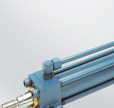
4 2 Air and Hydraulic Cylinders NFPA Industrial Type AVENTICS Corporation Magnetic piston standard for sensors. TaskMaster Pneumatic Cylinder Design Features, 1-1/2-4 Bores Technical Data, 1-1/2" - 4" bore sizes Standard Features include: Pressure rating: 200 psi air Temperature range: 0 F to 160 F ambient (for other temperature ranges, contact factory). Three integral mounts (head, cap and MS4), plus ten additional NFPA mountings available. Piston Rod: Case hardened to Rockwell "C" chrome-plated and finished to 15 micro-inches or better (5/8" not case hardened). Tube: Hard anodized alloy aluminum for light weight, high strength, & maximum corrosion resistance. Pre-Lubricated Design: Teflon-coated piston and polyurethane rod seals plus factory pre-lubrication eliminates the need for air line lubrication. Two versions available: TM-1 series is NFPA compliant including rod threads and ports, TM-8 series replaces the original TaskMaster design. Magnetic piston standard in all cylinders for sensor applications. Oversize rods available as a standard option. Stop tubes are available for long stroke, heavy side load applications. Viton seals available for all seals except piston and cushion seals Ports and cushions can be placed in any quadrant for maximum design flexibility. Smooth head and cap design eliminates gathering of foreign material. Ports: NPTF dryseal tapered threads, oversize ports available. Rod End Threads: KK1 male, KK2 male, KK1 female or KK1 studded male threads. Ports at quadrant 1, cushions at quadrant 2 (both can be ordered in different locations). Teflon Coated Cup Buna N Type, low-friction piston seals are wear-compensating for extended service life. Non-metallic wear strip provides extended service even under harsh side loads. Needle valve provides accurate external cushion adjustment. Positive rod seal. Pressure energized, polyurethane cup seal is wear compensating for longer life. Long-life rod bearing is corrosion resistant graphite. Operates efficiently even under conditions of marginal lubrication. Rod cartridge can be replaced without cylinder disassembly. Protective rod wiper increases cylinder life preventing dirt from entering rod gland. Rugged, non-corroding aluminum tubing is hard anodized for longer cylinder life, and features smooth profile. High strength steel piston rod. Hard chromium plated for maximum durability. Stainless (1-1/2 to 4 bore version shown above.) Self aligning cushions. Teflon coated floating check valve allows greater cylinder speed. Strong, fatigue-resistant rod threads. Smooth, anodized aluminum head and cap design eliminates gathering of foreign material. 1-1/2-4 Bore Style 5-6 Bore Style Proximity Switch Cylinder/Valve Combination Integral Position Sensor
5 Air and Hydraulic Cylinders NFPA Industrial Type AVENTICS Corporation 3 TaskMaster Pneumatic Cylinder Design Features, 1-1/2-4 Bores Model Code - Taskmaster Cylinders up to 4 Bore TaskMaster Cylinder Model Codes T M - X X X X X X - X X X X X STROKE - 1/8 INCREMENTS STROKE - WHOLE INCH Strokes over 99 7/8 require a special code CUSHIONING (Not recommended for <3 stroke) 0 None 1 Head 2 Cap 3 Head and Cap ZERO ADDITIONAL DESIGNATION 0 0 STANDARD 0 1 DOUBLE ROD 0 2 MT1 MOUNT INTEGRAL TO HEAD (New Design TM-1 only) 0 3 MT2 MOUNT INTEGRAL TO CAP (New Design TM-1 only) VALVE COMBO WITH BRACKETS & TUBES VALVE COMBO W/O BRACKETS & TUBES SEAL MATERIAL 0 BUNA 9 VITON (piston and cushion seals are not Viton) ROD SIZE* AND THREAD 1 1-1/ / / /2-2-1/2 ROD SIZE THREAD 3 1/4-4 ROD SIZE THREAD 0 FIRST ROD SIZE, KK1 MALE 5/8 7/ / FIRST ROD SIZE, KK2 MALE 5/8 1/ / FIRST ROD SIZE KK1 FEMALE 5/8 7/ / FIRST ROD SIZE KK1 STUDDED MALE 5/8 7/ / SECOND ROD SIZE, KK1 MALE 1 3/ / SECOND ROD SIZE, KK2 MALE 1 7/ /8 1-1/ SECOND ROD SIZE, KK1 FEMALE 1 3/ / SECOND ROD SIZE, KK1 STUDDED MALE 1 3/ / *Oversize Rod / Ports available only on TM-1 (NFPA compliant) BORE SIZE TASKMASTER PRODUCT 0 CUSTOM 1 NEW DESIGN WHOLE CYLINDER 8 OLD STYLE WHOLE CYLINDER Old custom cylinders converted to new format will be the old part number with the P replaced by TM Eample: P will become TM Custom cylinders begin with Model code example: T M - T M X X X X X and proceed sequentially from there X X X X X is standard suffix format Customer cylinder are assigned by factory only! New design cylinder, 2 bore, first rod size, buna seals, cushions both ends, 12-5/8 stroke

6 4 Air and Hydraulic Cylinders NFPA Industrial Type AVENTICS Corporation TaskMaster Pneumatic Cylinder Design Features, 1-1/2-4 Bores Common MS4 (Basic) Cylinder Part Numbers Common cylinder model numbers with integral MS4 mount are listed here. For other cylinders, see How To Order section. The basic TASKMASTER Cylinder is furnished with 3 possible means of mounting: side tapped (MS4) cap flush, head male rabbet. Twelve popular mounting kits can be assembled to the basic cylinder and are shown on the following pages. Mounting kits should be ordered separately from the cylinder. Mounting kit part numbers and accessory part numbers follow. For part numbers listed here, rod threads are KK2 male for the TM-8 series. For TM-1 series listed, rod threads are KK1 male. See How To Oder section for complete breakdown 1.5 Bore 2 Bore (Original replacement TM-8) Rod thread KK2 = 1/2-20 Port size EE = 1/4 NPTF Part Number Model No. R R R R R R R R R R R TM TM TM TM TM TM TM TM TM TM TM (Original replacement TM-8) Rod thread KK2 = 1/2-20 Port size EE = 1/4 NPTF Part Number Model No. (NFPA Compliant TM-1) Rod thread KK1 = 7/16-20 Port size EE = 3/8 NPTF Part Number Model No. Description R R R R R R R R R R R TM TM TM TM TM TM TM TM TM TM TM X 1 (non-cush) 1.5 X 2 (non-cush) 1.5 X 3 (non-cush) 1.5 X 4 (cushioned) 1.5 X 5 (cushioned) 1.5 X 6 (cushioned) 1.5 X 7 (cushioned) 1.5 X 8 (cushioned) 1.5 X 9 (cushioned) 1.5 X 10 (cushioned) 1.5 X 12 (cushioned) (NFPA Compliant TM-1) Rod thread KK1 = 7/16-20 Port size EE = 3/8 NPTF Part Number Model No. Description R R R R R R R R R R R TM TM TM TM TM TM TM TM TM TM TM R R R R R R R R R R R TM TM TM TM TM TM TM TM TM TM TM X 1 (non-cush) 2 X 2 (non-cush) 2 X 3 (non-cush) 2 X 4 (cushioned) 2 X 5 (cushioned) 2 X 6 (cushioned) 2 X 7 (cushioned) 2 X 8 (cushioned) 2 X 9 (cushioned) 2 X 10 (cushioned) 2 X 12 (cushioned)
7 Air and Hydraulic Cylinders NFPA Industrial Type AVENTICS Corporation 5 TaskMaster Pneumatic Cylinder Design Features, 1-1/2-4 Bores 2.5 Bore 3.25 Bore 4 Bore (Original replacement TM-8) (NFPA Compliant TM-1) Rod thread KK2 = 1/2-20 Rod thread KK1 = 7/16-20 Port size EE = 1/4 NPTF Port size EE = 3/8 NPTF Part Number Model No. Part Number Model No. Description R R R R R R R R R R R TM TM TM TM TM TM TM TM TM TM TM R R R R R R R R R R R TM TM TM TM TM TM TM TM TM TM TM X 1 (non-cush) 2.5 X 2 (non-cush) 2.5 X 3 (non-cush) 2.5 X 4 (cushioned) 2.5 X 5 (cushioned) 2.5 X 6 (cushioned) 2.5 X 7 (cushioned) 2.5 X 8 (cushioned) 2.5 X 9 (cushioned) 2.5 X 10 (cushioned) 2.5 X 12 (cushioned) (Original replacement TM-8) Rod thread KK2 = 7/8-14 Port size EE = 3/8 NPTF (NFPA Compliant TM-1) Rod thread KK1 = 3/4-16 Port size EE = 1/2 NPTF Part Number Model No. Part Number Model No. Description R R R R R R R R R R R TM TM TM TM TM TM TM TM TM TM TM R R R R R R R R R R R TM TM TM TM TM TM TM TM TM TM TM X 1 (non-cush) 3.25 X 2 (non-cush) 3.25 X 3 (non-cush) 3.25 X 4 (cushioned) 3.25 X 5 (cushioned) 3.25 X 6 (cushioned) 3.25 X 7 (cushioned) 3.25 X 8 (cushioned) 3.25 X 9 (cushioned) 3.25 X 10 (cushioned) 3.25 X 12 (cushioned) (Original replacement TM-8) Rod thread KK2 = 7/8-14 Port size EE = 3/8 NPTF (NFPA Compliant TM-1) Rod thread KK1 = 3/4-16 Port size EE = 1/2 NPTF Part Number Model No. Part Number Model No. Description R R R R R R R R R R R TM TM TM TM TM TM TM TM TM TM TM R R R R R R R R R R R TM TM TM TM TM TM TM TM TM TM TM X 1 (non-cush) 4 X 2 (non-cush) 4 X 3 (non-cush) 4 X 4 (cushioned) 4 X 5 (cushioned) 4 X 6 (cushioned) 4 X 7 (cushioned) 4 X 8 (cushioned) 4 X 9 (cushioned) 4 X 10 (cushioned) 4 X 12 (cushioned) MODEL NUMBER CONVERSION Current Versions Bore 1960 s 1970 s 1980 s-90 s TM-8-Series TM-1-Series 1 1/2 P P P TM TM P P P TM TM /2 P P P TM TM /4 P P P TM TM P P P TM TM
8 6 Air and Hydraulic Cylinders NFPA Industrial Type AVENTICS Corporation TaskMaster Pneumatic Cylinder MS4 Basic Cylinder Specifications MS4 (Basic Cylinder) / Side Tapped Mounting BASIC CYLINDER - MODUALR DESIGN. Refer to these tables for dimensions not shown on other mounts, or those affected by rod size. All dimensions are in inches unless otherwise indicated. TaskMaster basic cylinder is furnished with 3 possible mounts: MS4 side-tapped mount, cap flush, or head male rabbet. Twelve popular mounting kits can be assembled to the basic cylinder and are detailed in the following sections. Mounting kits should be ordered separately from the cylinder; for basic cylinder part numbers, see How to Order section or Common Cylinder Part Numbers section. MS4 Table 1. Dimensions affected by rod diameter. (Dimensions in inches) Bore Size MM ROD W [TM-8] Oversized rods and ports are not available for TM-8 series MS4 Table 1. (cont.) Dimensions affected by rod diameter MS4 Table 2. Dimensions not affected by rod diameter *For rod, P= 2.84 W [TM-1] EE [TM-8] EE [TM-1] RM DT (cap) DT (Head) ZJ [TM-8] ZJ [TM-1] A [TM-8] A [TM-1] /4 3/ / /4 3/ / /4 3/ / /8 1/ / /8 1/ / BORE SIZE MM ROD Y [TM-8] Y [TM-1] XT [TM-8] D XT [TM-1] BORE E G J P V AA LB NT RC RT SN TN SIZE / / / / / / * / / / / NA
9 Air and Hydraulic Cylinders NFPA Industrial Type AVENTICS Corporation 7 TaskMaster Pneumatic Cylinder MS4 Basic Cylinder Specifications Rod Size/Thread Options TASKMASTER ROD THREAD OPTIONS Male Rod Female Rod Studded Rod Rod thread options TM-8 TM-1 Bore Size MM Rod Male Female KK1 Male Stud A W A W 1-1/2, 2, 2-1/2 1-1/2, 2, 2-1/2 3-1/4, 4 3-1/4, /2-20 7/8-14 7/ /4-12 7/ /4-16 3/ / /4-16 3/ / /4-16 3/ Male threads available in KK1 and KK2 thread sizes. Female threads available in KK1 thread only. KK1 studded male rod end available. Note: Oversize rods were not available on earlier models, therefore not available on TM-8 series.
 Part Number MF1 Kit Part Number BORE SIZE MM ROD E F R W* FB LB TF UF WA* ZJ* WEIGHT R432013373 1.500 0.625 2.00 0.38 1.43 0.59 0.34 4.03 2.75 3.38 0.")
10 8 Air and Hydraulic Cylinders NFPA Industrial Type AVENTICS Corporation TaskMaster Pneumatic Cylinder MF1 Flange Mounting Kits thru 4 bore MF1 Flange Mounting Kit (Aluminum) Part Number MF1 Kit Part Number BORE SIZE MM ROD E F R W* FB LB TF UF WA* ZJ* WEIGHT R lb. 4 oz. R lb. 8 oz. R lb. 12 oz. R ** lb. 4 oz. R lb. 12 oz. Mounting kit only, order cylinder separately. These kits fit first and second rod sizes. Dimensions in inches, for those not shown see MS4 basic cylinder drawing. *Dimensions are for TM-8 series, for TM-1 series see MS4 basic cylinder drawing. **Dimensions not NFPA standard, and differs from E dimension on cylinder, see basic MS4 cylinder drawing. MF2 Flange Mounting Kit (Aluminum) Model MF2 Kit Part Number BORE SIZE MM ROD E F R W* FB LB TF UF WA* ZJ* WEIGHT R lb. 4 oz. R lb. 8 oz. R lb. 12 oz. R ** lb. 4 oz. R lb. 12 oz. Mounting kit only, order cylinder separately. These kits fit first and second rod sizes. Dimensions in inches, for those not shown see MS4 basic cylinder drawing. *Dimensions are for TM-8 series, for TM-1 series see MS4 basic cylinder drawing. **Dimensions not NFPA standard, and differs from E dimension on cylinder, see basic MS4 cylinder drawing.
11 Air and Hydraulic Cylinders NFPA Industrial Type AVENTICS Corporation 9 TaskMaster Pneumatic Cylinder MP1 Clevis Mounting Kits thru 4 bore MP1 Clevis Mounting Kit (Cast Iron), includes pivot pin Model Kit Part Number BORE SIZE MM ROD MP1 E F L W* CB CD CW LB LR MR XC* ZC* ZJ* WEIGHT R lb. 6 oz. R lb. 0 oz. R lb. 4 oz. R lb. 8 oz. R lb. 8 oz. Mounting kit only, order cylinder separately. These kits fit first and second rod sizes. Dimensions in inches, for those not shown see MS4 basic cylinder drawing. *Dimensions are for TM-8 series, for TM-1 series see MS4 basic cylinder drawing. MP2 Clevis Mounting Kit (Aluminum and Steel), includes pivot pin Model MP2 Bore Size/ (Kit Material) Kit Part Number Weight MM Rod E F L M W* CB CD CW LB LR MR XD* ZD* ZJ* 1.5 (Alum.) 1.5 (Steel) 2.0 (Alum.) 2.0 (Steel) 2.5 (Alum.) 2.5 (Steel) 3.25 (Alum.) 3.25 (Steel) 4.0 (Alum.) 4.0 (Steel) R R R R R R R R R R lb. 8 oz. 0 lb. 14 oz. 0 lb. 8 oz. 1 lb. 4 oz. 0 lb. 12 oz. 1 lb. 8 oz. 1 lb. 12 oz. 3 lb. 12 oz. 2 lb. 4 oz. 4 lb. 12 oz Mounting kit only, order cylinder separately. These kits are not affected by rod size. Dimensions in inches, for those not shown see MS4 basic cylinder drawing. *Dimensions are for TM-8 series, for TM-1 series see MS4 basic cylinder drawing
12 10 Air and Hydraulic Cylinders NFPA Industrial Type AVENTICS Corporation TaskMaster Pneumatic Cylinder MP4 Mounting Kits thru 4 bore MP4 Eye Bracket Mounting Kit (Aluminum) Model Kit Part Number BORE SIZE MM ROD E F L M W* CD MP4 EW LB LR MR XD* ZD* ZJ* WEIGHT R lb. 8 oz. R lb. 8 oz. R lb. 9 oz. R lb. 7 oz. R lb. 12 oz. Mounting kit only, order cylinder separately. These kits fit first and second rod sizes. Dimensions in inches, for those not shown see MS4 basic cylinder drawing. *Dimensions are for TM-8 series, for TM-1 series see MS4 basic cylinder drawing. MS1 Mounting Kit (Steel) Model Bore Size Kit Part Number Weight MM Rod MS1 E W* AB AH AL AO AT DD LB RA SA XA* ZA* ZB* R lb. 6 oz / R lb. 8 oz / R lb. 9 oz / R lb / R lb. 0 oz / Mounting kit only, order cylinder separately. These kits fit first and second rod sizes. Dimensions in inches, for those not shown see MS4 basic cylinder drawing. *Dimensions are for TM-8 series, for TM-1 series see MS4 basic cylinder drawing.
13 Air and Hydraulic Cylinders NFPA Industrial Type AVENTICS Corporation 11 TaskMaster Pneumatic Cylinder MS2 Mounting Kits thru 4 bore MS2 Mounting Kit (Steel) 1 1/2-2 1/2 Bore Model Kit Part Number Weight Bore Size MM Rod MS2 C F K W* SB SS ST SU SW SY SZ TS US XS* ZB* R lb. 6 oz R lb. 6 oz R lb. 6 oz Mounting kit only, order cylinder separately. These kits fit first and second rod sizes. Dimensions in inches, for those not shown see MS4 basic cylinder drawing. *Dimensions are for TM-8 series, for TM-1 series see MS4 basic cylinder drawing. MS2 Mounting Kit (Steel) 3 1/4-4 Bore Model Kit Part Number Weight Bore Size MM Rod MS2 E K W* SB SS ST SU SW SX SY SZ TS US XS* ZB* R lb. 12 oz R lb. 4 oz Mounting kit only, order cylinder separately. These kits fit first and second rod sizes. Dimensions in inches, for those not shown see MS4 basic cylinder drawing. *Dimensions are for TM-8 series, for TM-1 series see MS4 basic cylinder drawing.

14 12 Air and Hydraulic Cylinders NFPA Industrial Type AVENTICS Corporation TaskMaster Pneumatic Cylinder MT1 Mounts thru 4 bore MT1 Front Trunnion 1 Mount - TM-1 Series [NFPA compliant] Complete Cylinder Dimensions MT1 [TM-1 Series Complete Cylinder Dimensions] BORE SIZE MM ROD E W AA LB TD TL UT XG ZJ WEIGHT lb. 2 oz lb. 12 oz lb. 15 oz lb. 9 oz lb. 0 oz lb. 10 oz lb. 7 oz lb. 9 oz lb. 5 oz lb. 7 oz. 1 These are complete cylinders, not bolt-on kits. Dimensions in inches, for those not shown see MS4 basic cylinder drawing MT1 Front Trunnion 2 Mounting Kit - TM-8 Series Only (Aluminum block with steel trunnion pins) Model KIT PART NUMBER BORE SIZE MM ROD MT1 [TM-8 Series] E F W AA LB TD TL UT XG ZJ WEIGHT R lb. 12 oz. R lb. 0 oz. R lb. 4 oz. R lb. 12 oz. R lb. 8 oz. 2 These kits are for replacement only. For new cylinder, MT1 must be specified with cylinder due to rod extension being required. Dimensions in inches, for those not shown see MS4 basic cylinder drawing.

15 Air and Hydraulic Cylinders NFPA Industrial Type AVENTICS Corporation 13 TaskMaster Pneumatic Cylinder MT2 Mounts thru 4 bore MT2 Trunnion 1 Mount - TM-1 Series [NFPA compliant] Complete Cylinder Dimensions WEIGHT BORE SIZE MT2 [TM-1 Series Complete Cylinder Dimensions] MM ROD E W AA LB TD TL UT XJ ZJ 2 lb. 2 oz lb. 12 oz lb. 15 oz lb. 9 oz lb. 0 oz lb. 10 oz lb. 7 oz lb. 9 oz lb. 5 oz lb. 7 oz Dimensions in inches, for those not shown see MS4 basic cylinder drawing. 1 These are complete cylinders, not bolt-on kits. MT2 Trunnion Mounting Kit - TM-8 Series only (Aluminum block with steel trunnion pins) Model MT2 [TM-8 Series] WEIGHT KIT PART NUMBER BORE SIZE MM ROD E F W AA LB TD TL UT XJ ZF ZJ 0 lb. 12 oz. R lb. 0 oz. R lb. 4 oz. R lb. 12 oz. R lb. 8 oz. R Part number is for mounting kit only. Dimensions in inches, for those not shown see MS4 basic cylinder drawing.
 MX kits. MX2 - Tie rods extended cap end: Order (1) MX kit. MX3 - Tie rods extended head end: Order (1) MX kit.")
16 14 Air and Hydraulic Cylinders NFPA Industrial Type AVENTICS Corporation TaskMaster Pneumatic Cylinder MX1, 2, 3, 4 - (Extended Tie Rods) Mounting Kit MX1, 2, 3, 4 Kits (Extended Tie Rods) Mounting Kit NOTE: MX1 - Tie rods extended both ends: Order (2) MX kits. MX2 - Tie rods extended cap end: Order (1) MX kit. MX3 - Tie rods extended head end: Order (1) MX kit. MX4 - Two tie rods extended both ends: Order (1) MX kit. Model MX1, 2, 3, 4 KIT PART NUMBER BORE SIZE MM ROD E G J V W* AA BB DD LB RM ZB* WEIGHT R / lb. 2 oz. R / lb. 4 oz. R / lb. 4 oz. R / lb. 6 oz. R / lb. 6 oz. Mounting kit only, order cylinder separately. These kits are not affected by rod size. Dimensions in inches, for those not shown see MS4 basic cylinder drawing. *Dimensions are for TM-8 series, for TM-1 series see MS4 basic cylinder drawing. D Double Rod Model Bore Size MM ROD D Double Rod E G V W* AA DT LD NT PA RC RT SM TN XT ZM* / / / / / / / / / / Dimensions in inches, for those not shown see MS4 basic cylinder drawing. *Dimensions are for TM-8 series, for TM-1 series see MS4 basic cylinder drawing.
17 Air and Hydraulic Cylinders NFPA Industrial Type AVENTICS Corporation 15 TaskMaster Pneumatic Cylinder MR3-1.5 thru 4 bore Nose Mounting Kit MR3 Nose Mounting Kit (TM-8 Series Only) BORE SIZE MM ROD MR3 Nose Mount Kit* STANDARD CYLINDER PREFIX (TM-8 Series) KIT PART NO.* WEIGHT TM R lb. 9 oz TM R lb. 12 oz TM R lb. 13 oz TM R lb. 4 oz TM R lb. 4 oz. These kits are for replacement only. For complete cylinders, order by description, using prefixes for cylinder shown. *TM-8 series only, not available for TM-1 series. Dimensions E F V W Y AA BF LB RM WA XT ZB BK - THD These dimensions are not affected by rod size. Dimensions in inches, for those not shown see MS4 basic cylinder drawing.


18 16 Air and Hydraulic Cylinders NFPA Industrial Type AVENTICS Corporation TaskMaster Pneumatic Cylinder Accessories thru 4 bore Female Rod Clevis (Aluminum) PART NO. BORE ROD THREAD KK R R , 2 & & /2-20 7/8-14 A CB CD CE CW ER WEIGHT Includes pivot pin, retaining rings and jam nut. For sizes not shown, see NFPA cylinder accessories lb. 9 oz. 1 lb. 0 oz. Eye Bracket (Aluminum) PART NO. WEIGHT BORE E F M AA CB CD DB FL LR MR R R R R R lb. 4 oz. 0 lb. 4 oz. 0 lb. 8 oz 1 lb. 4 oz. 1 lb. 8 oz Eye bracket mates with female rod clevis or MP1, MP2 mounts

19 Air and Hydraulic Cylinders NFPA Industrial Type AVENTICS Corporation 17 TaskMaster Pneumatic Cylinder Accessories thru 4 bore Female Rod Eye (Steel) PART NO. BORE THREAD KK A CA CB CD ER WEIGHT R R , 2 & & 4 1/2-20 7/8-14 For sizes not shown, see NFPA cylinder accessories lb. 5 oz. 1 lb. 0 oz. Clevis Bracket (Aluminum) PART NO. WEIGHT BORE E F M AA CB CD CW DD FL LR MR R R R R R lb. 4 oz. 0 lb. 4 oz. 0 lb. 8 oz. 1 lb. 2 oz. 1 lb. 8 oz Clevis bracket mates with female rod eye or MP4 mount. For sizes not shown see NFPA cylinder accessories


20 18 Air and Hydraulic Cylinders NFPA Industrial Type AVENTICS Corporation TaskMaster Pneumatic Cylinder Accessories thru 4 bore Pivot Pin (Steel), includes retaining rings PART NO. WEIGHT BORE CD CL CP R R R lb. 4 oz. 0 lb. 8 oz. 0 lb. 13 oz. For sizes not shown, see NFPA cylinder accessories. 1.5, 2 & , 4 & Right Angle Flow Controls Series NPTF ports Mounting directly on cylinder, thread sealant on male threads. 360 swivel compact body. See SC-400 for additional details HOW TO ORDER: Part Number Description R R R R R R R R R R Threaded inlet, 1/4 NPTF with screwdriver slot Threaded inlet, 3/8 NPTF with screwdriver slot Threaded inlet, 1/2 NPTF with screwdriver slot Threaded inlet, 1/4 NPTF with knob adjustment Threaded inlet, 3/8 NPTF with knob adjustment Threaded inlet, 1/2 NPTF with knob adjustment Push-in fitting, 1/4 NPTF x 1/4 tube, with slot Push-in fitting, 3/8 NPTF x 3/8 tube, with slot Push-in fitting, 1/4 NPTF x 1/4 tube, with knob Push-in fitting, 3/8 NPTF x 3/8 tube, with knob
 LED indicators")
21 Air and Hydraulic Cylinders NFPA Industrial Type AVENTICS Corporation 19 TaskMaster Pneumatic Cylinder Optional Configurations Proximity Switches for 1 1/2-4 bore Taskmaster Cylinders Features Switch specifications For all bore sizes of Taskmaster Cylinders New, low profile designs Meets NEMA 1, 4, and 13 Easy to adjust Handles from 6 VDC to 120 VAC (unless otherwise indicated) LED indicators Built-in surge suppression Single pole, normally open 0 F to 160 F Operation AVENTICS magnetically operated Proximity Switches are the normally open, single pole, and single throw style. The switch is designed to close in the presence of a magnetic field, produced by the magnetic piston of the cylinder. Signals, useful for operating lights, valves, or other devices, are possible anywhere along the stroke of the cylinder. Multiple switches may be spaced as close as 0.62 inches by using more than one rib of the cylinder for mounting. Part No. (all included clamp) Symbol Type Bore Size Fig. ma Rating Part No. Desc. & Cable Length L Reed Reed Reed Reed Reed Reed Reed Reed Reed & 5 2 & 5 2 & 3 2 & & 5 1 & 5 1 & 3 1 & R R R P R R R R P Surge suppression, LED, 3 leads Surge suppression, LED, 12 leads Surg. supp., LED, Brad Harrison, 1 leads Surg. supp., LED, Molex/GM, 4 leads 3-pin quick disconnect (8mm), 6 leads Pigtail, two 3 leads Pigtail, two 9 leads Brad Harrison 1 leads Molex/GM NPN & 5 300/6-24VDC R pigtail NPN /6-24VDC R pin quick disconnect (8mm), 6 leads PNP & 5 300/6-24VDC R pigtail PNP /6-24VDC R pin quick disconnect (8mm), 6 leads Note: See following page for 3-pin connector cables with female connector Proximity Switch & Clamp - Figure 1

22 20 Air and Hydraulic Cylinders NFPA Industrial Type AVENTICS Corporation TaskMaster Pneumatic Cylinder Optional Configurations Proximity Reed Switch & Clamp - Figure 2 Connector Styles Schematic Figure No. Description 3 Brad Harrison Style 4 Molex/GM Style 5 Pigtail
23 Air and Hydraulic Cylinders NFPA Industrial Type AVENTICS Corporation 21 TaskMaster Pneumatic Cylinder Optional Configurations Integral Position Sensor The TASKMASTER Cylinder with Integral Position Sensor includes an internal position sensor (potentiometer) for infinite rod position indication. Application Used where knowledge of cylinder position is needed through entire stroke, at a point remote from the cylinder. A voltmeter graduated in inches or percent may be used as a position read-out device. Integral Position Sensor Sensor Features Integrated into cylinder, hence protected from external damage Conductive plastic construction Resistance approximately 1500 ohms per inch Linearity 1 percent of stroke Temperature range 0 to 160 F (-40 F optional) Maximum power rating 0.1 watts per inch Electrical connection: DIN connector (same as Series 740 Valve) Can be checked with simple voltmeters Does not require non-rotating rod Position sensing is absolute (not incremental); Position indication is not lost after power failure Cylinder Specifications 1.5 thru 4 bore Taskmaster cylinders All standard mounts applicable Cushioning available Strokes: 4, 6, 8, 10, 12 inches. Additional strokes available in 2 increments, 18 maximum. Part Number and Stroke (KK2 Male rod thread) Bore 4 Stroke 6 Stroke 8 Stroke 10 Stroke 12 Stroke R R TM TM R Other rod end thread options are available on request. Electro-Pneumatic Positioner Specifications R R TM TM R TM R TM TM TM Stroke Any length in 1 increments, to 10 2 increments between 10 and 16 strokes Accuracy +/-.050 or 1 percent full stroke, whichever is greater Repeatability +/-.050 Stroking Speed Approximately: Fast 2 /sec., slow.5 /sec. Operating Temp. 41 F to 122 F Power Requirements 24vdc, 600ma Signal Options 0Ö10vdc, 0Ö20ma, 5k ohm pot. Feedback Device Linear potentiometer, internally mounted Supply Pressure 100 psi nominal, 125 psi max. at 3 micron filtration recommended Optional Meter Drive 0-20ma Application Wherever infinite positioning requirements allow electrical analog control signals. Interfaces with computer, PLC or simple potentiometer. Consists of cylinder with integral sensor, optimized valving, and an electronic controller. Available in bore sizes 1-1/2 thru 4 and strokes up to 16 ; single or dual stroking speed control available. R TM TM TM TM TM R TM TM R Load Capacities per Bore Size Bore Size (inches) Load rating (lbs.) At 100 psi supply pressure, 1 percent positioning accuracy.


24 22 Air and Hydraulic Cylinders NFPA Industrial Type AVENTICS Corporation TaskMaster Pneumatic Cylinder Optional Configurations The basic concept involves a cylinder with integral feedback potentiometer in conjunction with a controller and matched solenoid valves. Figure 1 represents the system layout. The figure represents a 2 speed system utilizing (4) 2-way solenoid valves (energized in pairs) for slow speed and a double solenoid, 4-way, closed center for fast speed. The two speed feature offers the fastest response without sacrificing accuracy. The single speed positioners are applied in areas that require accuracy and only slow speed, or fast speeds that do not require 1% accuracy. For single speed applications, only one set of valves is necessary. For the slow retract, (mv1) and (mv3) solenoid valves are energized simultaneously. Valves (mv2) and (mv4) are energized for the slow extend command. The double solenoid valve is energized for either the fast retract or for fast extend. The controller constantly monitors the command signal and compares the feedback signal the position sensor located in the cylinder. If the command signal is greater than the feedback, the controller will energize the solenoid valves associated with extension. The retract solenoid valves are energized when the command signal is less than the feedback signal. If the command equals the feedback signal, all of the solenoid valves are De-energized and position is maintained. The two speed controller consists of a narrow window and a wide window comparator. A large difference between the command and feedback results in energization of both sets of solenoid valves. When the position approaches the set-point command, only the slow speed valves are energized. A unique feature is that each set of solenoids is pulsed before complete shut-off to provide a stepped, gradual deceleration of the load. The width of sensitivity and the width of the deceleration is adjustable on the controller to allow tailoring of the positioner for each application. E-P Positioner Selection HOW TO SELECT: 1. Determine the amount of force required for the application. 2. Determine the available supply pressure. 3. Not length of stroke required. 4. Check and note accuracy and speed requirements. 5. Determine if meter drive output is desired. 6. Contact sales representative or factory for component selection.

25 Air and Hydraulic Cylinders NFPA Industrial Type AVENTICS Corporation 23 TaskMaster Pneumatic Cylinder Optional Configurations Taskmaster Cylinder/Series 740 Valve Combination Specifications 1-1/2, 2 2-1/2, 3-1/4, & 4 Bore 100 stroke maximum, 1/4 minimum stroke Male or female rod thread Pressure: Temperature: 5 F to 140 F Standard Voltages: 6-24 VDC VAC Non-lube cylinder Positive air cushions at both ends (optional) Most NFPA mounts 20 to 150 psi (2 position valves) 50 to 150 psi (3 position valves) Features Air pilot or solenoid operated, single or double 2 position spring returned valve or 3 position closed center valve Indicator light optionally available Valve has built in flow controls and integrated fittings Manual override Valve mounts at head or cap Valve has polyacetal body Corrosion resistant package, pre-lubricated Reduced air consumption Simplified customer plumbing Easy valve interchange (no screws to remove) Reduce labor cost Valves are not factory assembled to cylinders. Valve mounting bracket and piping are factory assembled. Additional Series 740 valve features and specifications may be found in the valve catalog pages. Select Series 740 valve from the following pages. Taskmaster Cylinders with Mounting Bracket and Piping - For TM-8 Series Only* Base Model Number Bore Rod Size KK2 Male Thread TM TM TM TM TM / /2 3-1/4 4 *TM-1 compliant cylinders are available; see order code. These TM-8 compliant cylinders include valve mounting bracket complete with tubing. Above cylinders are modified to accept mounting bracket. Standard Taskmaster cylinders may be modified by ordering field mounting kit, Part Number R (does not contain piping from head to cap). Estimated operating speeds in inches per second at 100 psi are: 1-1/2 bore, 50; 2, 28; 2-1/2, 18; 3-1/4, 9; and 4, 7. 5/8 5/8 5/ /2-20 1/2-20 1/2-20 7/8-14 7/8-14 How to Order Series 740 Combinations Select the appropriate part number from the list and add the 4-digit suffix which describes cushioning and stroke. Order mounting kits separately. 4-DIGIT SUFFIX EXPLANATION The first digit indicates the degree of cushioning... 0-Noncushioned 1-Cushioned in head end only 2-Cushioned in cap ends only 3-Cushioned in both ends Second and third digits are used to indicate the stroke in inches. Fourth digit is used to indicate additional eights of an inch of stroke,

26 24 Air and Hydraulic Cylinders NFPA Industrial Type AVENTICS Corporation TaskMaster Pneumatic Cylinder Optional Configurations Series 740 Valve Options Type Diaphragm poppet valve Pressure range Minimum 20 psi Flow Maximum 150 psi C v = 0.7 to 0.95 Temperature range Solenoid 5 F to 122 F Air Pilot 5 F to 140 F Medium Compressed air, lubricated or non-lubricated Port sizes 3/8 ; 5/16 and 8mm also available [not shown] Materials Body / Seals Polyacetal plastic w/ Buna N seals Operating voltages DC ± 10% 50 Hz AC - 20% + 10% 60 Hz AC - 10% + 20% Power Consumption DC 24 V 2, 14 W Inrush power AC 220/230 V 50/60 Hz 6,60 / 5,50 VA Holding power AC 220/230 V 50/60 HZ 4,18 / 3,30 VA Protection with el. Connector NEMA 4 [IP 65 to DIN VDE 0470] Duty cycle ED 100% Switching times t on 18 ms [24VDC at 85 psi] t off 32 ms Note Electrical connectors must be ordered separately; one per solenoid required. For entire line of Series 740 Valve options and accessories, see SC-300 catalog. Series 740 Valve - Air Pilot Part Number R R Series 740 Valve - 2 Position, Solenoid Operated Description Single Air Pilot, spring return Double Air Pilot, 2 position Single Solenoid, Air Spring Return Description Double Solenoid V-50Hz/120V-60Hz R V-50Hz/240V-60Hz R VDC R VDC VDC R VAC-50/60Hz Series 740 Valve - 3 Position, Double Solenoid Operated R R R R R R Closed Center Description Exhaust Open Center R R R R R R V-50Hz/120V-60Hz 220V-50Hz/240V-60Hz 6 VDC 12 VDC 24 VDC 24 VAC-50/60Hz R R R R R Caution: Simultaneous activation of both solenoids will provide full supply pressure to both delivery and exhaust ports. Care should be taken to avoid applications where a back pressure spike can occur from heavy inertia loads. Solenoid Connectors - Order One per Solenoid Strain Relief Connectors Description 1/2 Conduit Connectors* R R (110 VAC) R (230 VAC) R (12 VDC) R (24 VDC) R (24 VAC) *CSA approved Non-lighted Non-lighted for Wireways Metallic Non-lighted Non-lighted Molded Plastic Lighted Lighted Lighted Lighted Lighted R R R (110V AC/DC) R (230V AC/DC) R (12V AC/DC) R (24V AC/DC)

27 Air and Hydraulic Cylinders NFPA Industrial Type AVENTICS Corporation 25 TaskMaster Pneumatic Cylinder Technical Data and Design Features, 5 and 6 bores Technical Data, 5-6 bore sizes Pressure Rating 200 psi maximum Temperature Range 0 to 160 F ambient, 200 F intermittent Medium Compressed air, non-lubricated or lubricated Strokes Furnished to nearest 1/8 Pneumatic Cushioning Optional on both ends Mountings One integral, plus ten NFPA mountings Ports NPTF dryseal tapered Materials Tube Hard anodized aluminum Tie Rods 303 Stainless Steel Head and Cap Die cast aluminum Piston Rod Steel, hard chrome plated, oversize available TaskMaster Design Features, 5-6 Design Features 1. Non-metallic wear strip provides extended service even under harsh side loads. 2. Pressure energized Teflon coated cup-type piston seals provide positive, low friction sealing. They are self-regulating and wear compensating for extended service life. 3. Highly accurate external cushion adjustment 4. Durable rod bearing. Dependable non-scoring, corrosion-resistant graphite material. Cartridge can be removed without cylinder disassembly. 5. Positive rod seal. Pressure energized polyurethane cup seal is wear compensating for longer life. 6. High strength steel piston rod. Hard chrome plated for maximum durability with a 100,000 psi minimum yield. Oversize rod available. Case hardened to Rockwell C, finished to 15 microinches or better. 7. Protective rod wiper. Polyurethane lip-type wiper increases cylinder life by preventing damaging dirt from entering the cylinder gland 8. Self-aligning cushions. Teflon-coated, floating check valve allows greater cylinder speed stainless steel tie rods for maximum corrosion resistance. 10.Rugged, non-corrosive tubing. Reinforced, hard anodized aluminum. Magnetic piston (for use with sensors) available as an option. Select appropriate sensor from proximity switch section.
28 26 Air and Hydraulic Cylinders NFPA Industrial Type AVENTICS Corporation TaskMaster Pneumatic Cylinder How To Order Cylinders - 5 and 6 bore Basic Ordering Code 5-6 Cylinders Cushion Head End EXAMPLE: Mounting Style Stroke Series Bore Cushion 5 X 6 C MF-1 TM C Part Number Listing: A current part number with description listing is available at Notes: The basic ordering code must accompany the part number when ordering. If the magnetic piston (for use with sensors) is desired, it must also be specified when ordering. Select sensor from proximity switch section. Normal stroke tolerance +/- 1/16 Cushioning not recommended for under 3 stroke. Old Part Numbers Reference for 5 and 6 bores 5 BORE PART NUMBER 5 BORE ROD DIA. 5 BORE ROD THREAD 5 & 6 MOUNT 6 BORE PART NUMBER 6 BORE ROD DIA. 6 BORE ROD THREAD P P P P P P P P P P P P P P / / / / / / / MF-1 MF-1 MF-2 MF-2 MF-5 MF-5 MF-6 MF-6 MP-2 MP-2 MS-1 MS-1 MS-4 MS-4 P P P P P P P P P P P P P P / / / / / / /4-12 MP1 mount available, contact factory 5 DIGIT SUFFIX EXPLANATION The first digit will always be zero. The second digit indicates the degree of cushioning: 0 - Non-cushioned 1 - Cushioned in head end only 2 - Cushioned in cap ends only 3 - Cushioned in both ends Third and fourth digits are used to indicate the stroke in inches. Fifth digit is used to indicate additional eights of an inch of stroke. EXAMPLE: Both ends cushioned, 10-1/2 stroke, 1-1/2 bore, KK2 THD = P
![Air and Hydraulic Cylinders NFPA Industrial Type AVENTICS Corporation 27 TaskMaster Pneumatic Cylinder MS4 5 and 6 bore Basic Cylinder MS4 [Basic Cylinder] EE = 5 bore 1/2-14 NPTF, 6 bore 3/4-14 NPTF](/docs-images/72/66804946/images/29-0.jpg "MS4 Mount Bore Size MM Rod E G J K P V W Y AA DT NA LB NT TAP RM SN TN XT ZB ZJ 5.00 5.00 6.00 6.00 1.00 1.38 1.38 1.75 5.50 5.50 6.50 6.50 2.31 2.31 2.69 2.69 1.19 1.19 1.44 1.44 0.61 0.61 0.61 0.61 2.")
29 Air and Hydraulic Cylinders NFPA Industrial Type AVENTICS Corporation 27 TaskMaster Pneumatic Cylinder MS4 5 and 6 bore Basic Cylinder MS4 [Basic Cylinder] EE = 5 bore 1/2-14 NPTF, 6 bore 3/4-14 NPTF MS4 Mount Bore Size MM Rod E G J K P V W Y AA DT NA LB NT TAP RM SN TN XT ZB ZJ /8-11 5/8-11 3/4-10 3/ and 6 bore Taskmaster pre-lubricated cylinders are versatile, durable, yet economical. The basic cylinder is furnished with MS4, side tapped mount with ten additional NFPA mountings available. Corrosion resistant aluminum head, cap and tube plus stainless steel tie rods make the Taskmaster Cylinder excellent where corrosion is a problem. These cylinders can be applied with medium-heavy loadings where large masses are to be moved or where frequency is high. The optional pneumatic cushioning is adjustable and gives quick acceleration. Each bore size offers the advantage of an oversize rod that can be used for larger loads and longer strokes. Dimensions in inches.
30 28 Air and Hydraulic Cylinders NFPA Industrial Type AVENTICS Corporation TaskMaster Pneumatic Cylinder Rod Thread Options Rod Size / Thread Options TASKMASTER ROD THREAD OPTIONS Male Rod Female Rod Studded Rod BORE SIZE MM ROD KK1 THD Rod Thread Options KK2 THD A D* W / /4-12 7/ / / / NOTE Male thread available in KK1 and KK2 thread sizes. KK1 male furnished when thread not specified. Female thread available in KK1 thread only. KK1 studded male rod end available on request. *D = width across rod flats


31 Air and Hydraulic Cylinders NFPA Industrial Type AVENTICS Corporation 29 TaskMaster Pneumatic Cylinder MF1-5 and 6 bore MF2 MF1 Head Rectangular Flange Model BORE SIZE MM ROD E F K R W FB LB TF UF WA ZB ZJ MF1 Head Rectangular Flange Dimensions in inches, for those not shown see MS4 basic cylinder drawing. MF2 Cap Rectangular Flange Model BORE SIZE MM ROD MF2 Cap Rectangular Flange E F K R W FB LB TF UF ZF ZJ Dimensions in inches, for those not shown see MS4 basic cylinder drawing.

32 30 Air and Hydraulic Cylinders NFPA Industrial Type AVENTICS Corporation TaskMaster Pneumatic Cylinder MF5-5 and 6 bore MF6 MF5 Head Square Flange Model BORE SIZE MM ROD MF5 Head Square Flange E F K R W FB LB TF UF WA ZB ZJ Dimensions in inches, for those not shown see MS4 basic cylinder drawing. MF6 Cap Square Flange (Steel) Model BORE SIZE MM ROD MF6 Cap Square Flange E F K R W FB LB TF UF ZF ZJ Dimensions in inches, for those not shown see MS4 basic cylinder drawing.

33 Air and Hydraulic Cylinders NFPA Industrial Type AVENTICS Corporation 31 TaskMaster Pneumatic Cylinder MP2-5 and 6 bore MS1 MP2 Detachable Clevis (Aluminum) Model MP2 Detachable Clevis BORE MM E F K L M CB CD CW LB LR MR XD ZD ZJ SIZE ROD Dimensions in inches, for those not shown see MS4 basic cylinder drawing. MS1 Side End Angles (Steel) Model BORE SIZE MM ROD MF1 Head Rectangular Flange E K AB AH AL AO AT LB RA SA XA ZA ZJ Dimensions in inches, for those not shown see MS4 basic cylinder drawing.

34 32 Air and Hydraulic Cylinders NFPA Industrial Type AVENTICS Corporation TaskMaster Pneumatic Cylinder MX1, MX2, MX3, MX4 5 and 6 bore D Double Rod MX1, MX2, MX3, MX4 Tie Rods Extended MX1 Tie rods extended both ends MX2 Tie rods extended cap end MX3 Tie rods extended head end MX4 Two tie rods extended both ends Model MX1, MX2, MX3, MX4 BORE MM Rod E K W AA BB DD LB ZB ZJ ZT SIZE / / / / Dimensions in inches, for those not shown see MS4 basic cylinder drawing. D Double Rod BORE SIZE MM ROD Technical Data E G K P V W Y AA DD DT EE LD NT RM SN TN XT ZL ZM / / / / / / / / / / / / Dimensions in inches, for those not shown see MS4 basic cylinder drawing.

 PART NO. WEIGHT BORE SIZE E F M AA CB CD DB FL LR MR R433012640 3 lbs. 4 oz. 5 3.50 0.63 3.60 1.25 0 0.50 1.88 1.")
35 Air and Hydraulic Cylinders NFPA Industrial Type AVENTICS Corporation 33 TaskMaster Pneumatic Cylinder Accessories 5 and 6 bore Female Rod Clevis (Steel) PART NO. BORE SIZE ROD SIZE A CB CD CE CH CW ER KK WGT. R / lbs. 4 oz. R * / lbs. 7 oz. R & lbs. 8 oz. R / lbs. 6 oz. R / lbs. 8 oz. * Aluminum. Dimensions in inches. Eye Bracket (Steel) PART NO. WEIGHT BORE SIZE E F M AA CB CD DB FL LR MR R lbs. 4 oz R lbs. 4 oz. 5 & R lbs. 4 oz R lbs. 12 oz Dimensions in inches. This part mates with female rod clevis, or MP1, MP2 mounts
36 34 Air and Hydraulic Cylinders NFPA Industrial Type AVENTICS Corporation TaskMaster Pneumatic Cylinder Accessories -- 5 and 6 bore Female Rod Eye (Steel) F PART NO. BORE SIZE ROD SIZE A CA CB CD ER KK WEIGHT R / lb. 4 oz. R / lb. 3 oz. R & lb. 8 oz. R & / lb. 6 oz. R / lb. 6oz. R / lb. 8 oz. Dimension in inches. Clevis Bracket (Steel) PART NO. WEIGHT BORE SIZE E F M AA CB CD CW DB FL LR MR R lb. 4 oz / R lb. 2 oz. 5 & / R lb. 8 oz / R lb. 0 oz / Dimensions in inches. This part mates with female rod eye or MP4 mount.

 Part Number Bore E F R AA CW CB CD DB FL LR MR M R432015746 5 5.50 0.62 4.10 5.80 0.63 1.26 0.53 1.25 0.88 0.")
37 Air and Hydraulic Cylinders NFPA Industrial Type AVENTICS Corporation 35 TaskMaster Pneumatic Cylinder Accessories -- 5 and 6 bore Pivot Pin (Steel), including retaining rings PART NO. BORE SIZE CD CL CP WEIGHT R lb. 8 oz. R & lb. 13 oz. R lb. 0 oz. R * lb. 14 oz. Dimensions in inches. *Has Cotter pins instead of retaining rings. MP1 Bracket Cast Iron (for mating with clevis bracket) Part Number Bore E F R AA CW CB CD DB FL LR MR M R R Dimensions in inches.
38 36 Air and Hydraulic Cylinders NFPA Industrial Type AVENTICS Corporation TaskMaster Pneumatic Cylinder Installation and Service Information DESCRIPTION TABLE OF CONTENTS INSTALLATION AND SERVICE INFORMATION PAGE NO. Description, Warning 36 Installation 36 Standard & Special Repair Kits (1-1/2-6 Bore) 37 Operation 38 Standard Specifications 38 Adjustments 38 General Maintenance & Repair Recommendations 38 Parts List & Assembly Drawing (1-1/2-4 Bore)* 39 Parts List & Assembly Drawing (1-1/2-4 Bore)** 40 Major Repair, Maintenance and Testing (1-1/2-4 Bore) 41 Basic Cylinder Parts List & Assembly Drawing (5 & 6 Bore) 42 Major Repair, Maintenance & Testing (5 & 6 Bore) 43 Double Rod Cylinder Assembly Drawings (All Bores) 44 GENERAL INFORMATION Taskmaster Pre-Lubricated Pneumatic cylinders are available in 1-1/2-6 bores. The basic cylinder is furnished with an MS4 side tapped mount, with up to 12 additional NFPA mountings available. The popular mounting kits can be assembled to the basic cylinder on the 1-1/2-4 bore. Most mounting kits should be ordered separately from the cylinder. Basic cylinder part numbers, mounting kit and accessory part numbers for 1-1/2-4 bore cylinders are listed on the catalog pages. The available mounting kits for 1-1/2-4 bore are MS4 (basic), MF1, MF2, MP1, MP2, MP4, MS1, MS2, MT1, M1, 2, 3, & 4. The current generation of 1-1/2-4 bore cylinders begin with TM model codes. Model codes beginning TM-8 are replacement for the original P number cylinders. Model codes beginning with TM-1 match MFPA standards for rod and port dimensions. The 5 and 6 bore cylinders are ordered with the desired mount. Part numbers for cylinders and accessories are listed on the catalog pages. The available mounts are: MS4, MF1, MF2, MF5, MF6,MP2, MS1, MX1, 2, 3, & 4. Double rod models are available in all bore sizes. WARNINGS INSTALLATION AND MOUNTING The user of these devices must conform to all applicable electrical, mechanical, piping and other codes in the installation, operations or repair of these devices. INSTALLATION! Do not attempt to install, operate or repair these devices without proper training in the technique of working with pneumatic systems and devices, unless under trained supervision. Compressed air systems contain high levels of stored energy. Do not attempt to connect, disconnect or repair these products when a system is under pressure. Always exhaust the pressure from an air system before performing any service work. Failure to do so can result in serious personal injury. Disconnect the electrical power supply before connecting or servicing a solenoid operated valve. MOUNTING! Devices should be mounted and positioned in such a manner that they cannot be accidently operated. INSTALLATION Outline dimensions for installation of basic cylinders, mounting kits, and cylinder accessories are shown on the catalog pages. Port sizes are shown on standard specification chart on page 38. Before mounting the cylinder, all air lines in the system should be blown clean to remove any harmful dirt or moisture. To prevent corrosion and an accumulation of foreign matter in the cylinder, a 10 MICRON or better AVENTICS filter should be installed in the supply line to the cylinder control valve. Teflon-coated piston and rod seals plus factory pre-lubrication, eliminates the need for air line lubrications. (However, lubricators can be used if desired). A complete selection of air line lubricators are available from AVENTICS. A very important consideration in mounting the Taskmaster cylinder is keeping the cylinder thrust as close as possible to the centerline of the piston rod and free of misalignment or side loading. Off-center thrust or side loads decrease the normal life of the rod bearing and seals, and can cause binding in the cylinder or linkage. Forcing rod, clevis pins, or mounting bolts into position indicates that the cylinder is not properly aligned, and permanent damage my result from such installation. *For model codes beginning in TM and date code of L or later. **For part numbers beginning with P Note: For TM part numbers with date code prior to L contact factory.
39 Air and Hydraulic Cylinders NFPA Industrial Type AVENTICS Corporation 37 TaskMaster Pneumatic Cylinder Installation and Service Information Repair Kits and Parts ROD CARTRIDGE KIT (See Note 1) Bore Rode Size Part Number 1-1/2, 2 & 2 1/2 5/8 3-1/4 & R R R R /8 1-3/8 1-3/4 R R R R (Std.) (Viton) (Std.) (Viton) (Std*) (Std*) (Std*) (Std*) PISTON & TUBE SEAL KITS Standard Cylinders (repairs all versions) Bore Part No. (std.)tube seals Part No. Viton Tube seals 1-1/2 R R R R /2 R R /4 R R R R R R ROD CARTRIDGE KIT (see Note 2) Description Part Number 1 1/2 bore, 5/8 rod, R /2 bore, 5/8 rod, non-cushioned R bore, 5/8 rod, R bore, 5/8 rod, non-cushioned R /2 bore, 5/8 rod, R /2 bore, 5/8 rod, non-cushioned R /4 bore, 1 rod, R /4 bore, 1 rod, non-cushioned R bore, 1 rod, R Description 4 bore, 1 rod R CUSHION KIT (see Note 1) Part Number 1-1/2 R , 2-1/2 R /4, 4 R Description 5 R R CYLINDER LUBE GREASE Part Number 14 oz. tube R (The cylinder is pre-lubricated at the factory. However, when replacing seals, lubricate all rubber parts with cylinder lube grease.) PISTON & LUBE SEAL KITS Magnetic (original version only) Includes tube seals, piston seals and piston wear strip. Bore Part Number 1-1/2 R R /2 R /4 R R MAGNETIC PISTON KIT* Bore Part Number 1-1/2 R R /2 R /4 R R *Replacement only, for orig. design Taskmaster. Includes Magnetic piston, followers, seals and magnets. PISTON KITS (see Note 3) Bore Part Number 1-1/2 R R /2 R /4 R R Note 1: For Part number starting in P. Also TM or R date code later than L10-00 or 00W41. Note 2: For part no. starting with TM with date code of L09-00 or before, standard seals, with Note 3: For part numbers starting with TM or R with date code later than L10-00 or 00W41
40 38 Air and Hydraulic Cylinders NFPA Industrial Type AVENTICS Corporation TaskMaster Pneumatic Cylinder Installation and Service Information OPERATION Air pressure supplied to the cap-end port moves the piston rod to its extended position. Pressure supplied to the head end port moves the piston rod to its retracted position. See the catalog for forces developed by each cylinder. 1 1/2 6 Bore General Information CYLINDER WEIGHTS* BORE SIZE ROD SIZE CYLINDER WEIGHT ZERO ADDITIONAL WEIGHT PER INCH STANDARD SPECIFICATIONS BORE SIZES NFPA standard, 1-1/2, 2, 2-1/2, 3-1/4, 4, 5, & 6 PRESSURE RATING 200 PSI air TEMPERATURE RANGE 0 F TO 160 F ambient STROKES Standard strokes furnished to near 1/8. Normal stroke tolerance +/- 1/16. Closer stoke tolerances available; consult factory. MOUNTING Basic mounting plus 12 additional NFPA mountings. CUSHIONING Optional on both ends for all bore sizes. PRE-LUBRICATED DESIGN Teflon-coated piston and rod seals plus factory pre-lubrication eliminates the need for air line lubrication. ROD END THREADS KK2 male thread is standard for 1-1/2 4 bores for TM-8 and P part numbers. KK1 male thread is standard for 1-1/2 4 bores for TM-1 part numbers. KK1 male thread is standard for 5 and 6 bore. KK1 female, KK1 (studded) male and either KK1 or KK2 male are optional on all bore sizes. PISTON ROD Chrome-plated, high carbon steel polished to 15 microfinish. Stainless steel (316/303) available for maximum corrosion resistance. Oversize rods are available on TM-1 models of 1-1/2-4 bores and on 5 and 6 bores. TUBE Hard anodized extruded aluminum for lightweight, high strength and maximum corrosion resistance used in 1 1/2-4. Seamless aluminum tubing used for 5 and 6 bore. PORTS NPTF dryseal tapered threads. Available only in sizes shown 1-1/2 5/ / /2 5/ / / / / *Weights based on standard (first) rod size. ADJUSTMENT An adjustment needle valve is furnished as an integral part of the head and cap on all cushioned cylinders. This needle valve controls the rate at which trapped air is allowed to vent from the head or cap. Turn the needle valve clockwise to increase the amount of cushioning and counter-clockwise to decrease the amount of cushioning. GENERAL MAINTENANCE & REPAIR RECOMMENDATIONS Maintenance periods should be scheduled in accordance with frequency of use and working environment of the cylinder. All cylinders must be visually inspected for wear and given an in system operating performance and leakage test at least once a year. If these visual observations indicate cylinder repair is required, the cylinder must be removed, repaired and tested. A major overhaul is recommended at one million cycles. However where frequency of use is such that it would require more than two years to obtain one million cycles, the cylinder must be overhauled at the two year period. When it is determined that the cylinder requires a major repair as a result of the one million cycles, one year routine inspection, or the two year service period has elapsed, the device must be disassembled, cleaned, inspected, parts replaced as required, rebuilt and tested for leakage, and proper operation prior to installation. Refer to MAJOR REPAIR, MAINTENANCE INSTRUCTION, and TEST PROCEDURES. BORE NPTF* NPTF** 1-1/2, 2, 2-1/2 1/4-18 3/ /2, 4 3/8-18 1/ / /4-14 *For TM-8 or P part numbers. **For TM-1 part numbers.
 Basic MS4 Parts List Single Rod Model* Part Number by Bore Size Ref. Qty.")
41 Air and Hydraulic Cylinders NFPA Industrial Type AVENTICS Corporation 39 TaskMaster Pneumatic Cylinder Installation and Service Information 1-1/2-4 Bore Size Basic Cylinder Parts List (For model numbers beginning with R, or TM and date code of L10 or later.) Basic MS4 Parts List Single Rod Model* Part Number by Bore Size Ref. Qty. Description 1-1/2" 2" 2-1/2" 3-1/4" 4" 1 4 Screw, Head R R R R R Head, TM-8 Cylinder R R R R R Head, TM-1 Cyl., Standard Rod R R R R R Head, TM-1 Cyl., Oversize Rod R R R R R Rod Cartridge Kit, Standard Rod R R R R R Rod Cartridge Kit, Oversize Rod R R R R R Retaining Ring, Rod Bearing Repair kit Repair kit Repair kit Repair kit Repair kit 4 1 Rod Bearing includes includes includes includes includes 5 1 Rod Wiper ref. numbers ref. numbers ref. numbers ref. numbers ref. numbers 6 1 Rod Seal 3, 4, 5 & 6 3, 4, 5 & 6 3, 4, 5 & 6 3, 4, 5 & 6 3, 4, 5 & Cushion Kit R R R R R Piston & Tube Seal Kit R R R R R Tube Seal O'ring Repair kit Repair kit Repair kit Repair kit Repair kit 9 1 Piston Rod Seal includes includes includes includes includes 10 2 Piston Seal ref. numbers ref. numbers ref. numbers ref. numbers ref. numbers 11 1 Piston Wear Ring 8, 9,10 & 11 8, 9,10 & 11 8, 9,10 & 11 8, 9,10 & 11 8, 9,10 & 11 Piston Kit, Standard Rod R R R R R Piston Kit, Oversize Rod R R R R R Piston Rep. kit incl. Rep. kit incl. Rep. kit incl. Rep. kit incl. Rep. kit incl Follower, Piston ref. numbers ref. numbers ref. numbers ref. numbers ref. numbers 14 1 Retaining Nut, Piston & Rod 8 thru 14 8 thru 14 8 thru 14 8 thru 14 8 thru Piston Rod, Male Std. Rod, KK1 or KK2 Thread various various various various various Oversize Rod, KK1 Thread various various various various various 15a 1 Piston Rod, Female Std. Rod, KK1 Thread various various various various various Oversize Rod, KK1 Thread various various various various various 16 1 Male Stud (use with ref. 15a) 7/16"-20 UNF-2A Thread various various various - - 1"-14 UNF-2A Thread various various various various various 3/4"-16 UNF-2A Thread various various 17 1 Tube, Body various various various various various 18 1 Cap, TM-8 (w/needle vlv. assbly) R R R R R Cap, TM-1 (w/needle vlv. assbly) R R R R R Screw, Cap R R R R R *Order repair parts for double rod cylinders by description and complete cylinder number. See page 44 for assembly drawing. *Single Rod Model
 Basic MS4 Parts List Single Rod Model* Part Number by Bore Size Ref. Qty.")
42 40 Air and Hydraulic Cylinders NFPA Industrial Type AVENTICS Corporation TaskMaster Pneumatic Cylinder Installation and Service Information 1-1/2-4 Bore Size Basic Cylinder Parts List (For part numbers beginning with P ) Basic MS4 Parts List Single Rod Model* Part Number by Bore Size Ref. Qty. Description 1-1/2" 2" 2-1/2" 3-1/4" 4" 1 4 Screw, Head R R R R R Head (w/needle valve assembly) R R R R R Rod Cartridge Kit R R R R R Retaining Ring, Rod Bearing Repair kit Repair kit Repair kit Repair kit Repair kit 4 1 Rod Bearing includes includes includes includes includes 5 1 Rod Wiper ref. numbers ref. numbers ref. numbers ref. numbers ref. numbers 6 1 Rod Seal 3, 4, 5 & 6 3, 4, 5 & 6 3, 4, 5 & 6 3, 4, 5 & 6 3, 4, 5 & Cushion Kit R R R R R Piston & Tube Seal Kit R R R R R Tube Seal O'ring Repair kit Repair kit Repair kit Repair kit Repair kit 9 1 Piston Rod Seal includes includes includes includes includes 10 2 Piston Seal ref. numbers ref. numbers ref. numbers ref. numbers ref. numbers 11 1 Piston Wear Ring 8, 9, 10 & 11 8, 9, 10 & 11 8, 9, 10 & 11 8, 9, 10 & 11 8, 9, 10 & Piston R R R R R Follower, Piston R R R R R Retaining Nut, Piston Rod R R R R R Piston Rod, Male 1/2"-20 Thread various various various - - 7/8"-14" Thread various various 15a 1 Piston Rod, Female 7/16"-20 Thread various various various - - 3/4"-16 Thread various various 16 1 Male Stud (use with ref. 15a) 7/16"-20 Thread - - 3/4"-16 Thread R R Tube, Body various various various various various 18 1 Cap (w/needle valve assembly) R R R R R Screw, Cap R R R R R *Order repair parts for double rod cylinders by description and complete cylinder number. See page 44 for assembly drawing.
43 Air and Hydraulic Cylinders NFPA Industrial Type AVENTICS Corporation 41 TaskMaster Pneumatic Cylinder Installation and Service Information 1-1/2-4 BORE MAJOR REPAIR, MAINTENANCE & TESTING MAJOR REPAIR & MAINTENANCE INSTRUCTIONS When it is determined that the cylinder requires shop repairs (see GENERAL MAINTENANCE AND REPAIR RECOMMENDATIONS), the following general instructions are recommended. DISASSEMBLY, CLEANING & LUBRICATION Follow warnings on page 36. Disconnect air lines from head and cap ports of cylinder. Completely disassemble the cylinder using the assembly views as reference. No special tools are required except internal snap ring pliers and hex wrench set to remove retaining rings, retaining nut, head & cap screws. A 5/32 socket wrench is required to remove needle valve retainer plate (present on older models). 1. Remove head & cap screws. 2. Remove head & cap. 3. Remove piston rod assembly. To disassemble piston rod, clamp piston rod across flats in soft jaws to remove piston retaining nut. Retaining nut is retained to piston rod with LOCTITE R/C Remove internal retaining rings to remove rod cartridge and cushion kits from head and cap. 5. Remove hex head screws and retainer plate to remove needle valve assembly. Wash all metal parts in a nonflammable solvent. Rinse each part thoroughly and blow dry with a low pressure air jet. Arrange the parts on a clean surface. Examine each part carefully. Replace all rubber parts and all other worn or damaged parts. The use of REPAIR KITS is strongly recommended. REASSEMBLY The procedure for reassembly is essentially the reverse of disassembly. However, the following exceptions should be noted: 1. All O-rings should be well coated with Cylinder Lube grease as they are installed in their respective grooves and prior to assembly with the mating part. (NOTE: for FOOD SERVICE USE, use NORDSTROM Grease; see page 37) Care must be taken when assembling O- rings and packing that they are not damaged, as this will cause leakage. 2. Assemble the piston followers, piston, and piston seals to the piston rod less lubricant. The piston retaining nut should be assembled with LOCTITE retaining compound R/C 277 and torque specification chart with the piston rod clamped in soft jaws. 3. Reassemble the cylinder using the assembly views as reference. Pay particular attention to the installation of the cushion kit (ref. 7) to insure that the tapered rubber surface marked THIS SIDE UP faces to the inside (piston side) of the cylinder. As the assembly proceeds, lubricate the piston seals, cushion seals, rod seal, tube, and the tube seals with Cylinder Lube grease. 4. Torque head and cap screws to torque specification shown on chart. TESTING After the cylinder has been completely reassembled, it should be tested, either on a test bench or in the regular installation. TEST PROCEDURE The cylinder should be tested for cushioning, travel and leakage. A. CUSHIONING 1. Turn both cushioning screws clockwise all the way in. 2. Cycle cylinder a few times by alternating supply pressure to head and cap ports. 3. Apply supply pressure to the head port. Rod should retract, decelerate and may stop before completion of stroke. 4. Apply supply pressure to the cap port. Rod should extend, decelerate and may stop before completion of stroke. B. TRAVEL AND LEAKAGE 1. Turn the cushioning screws counterclockwise on (1) full turn. 2. Apply supply pressure to the head port. Cylinder should have less cushioning and make full stroke + or Check leakage around rod seal. No leakage permitted. 3. Apply supply pressure to the cap port. Cylinder should have less cushioning and make full stroke + or.062. Check leakage at head port. 30cc/min. leakage permitted. 4. Return piston rod to retract position by applying supply pressure to head port. Remove supply pressure and install cylinder in service if satisfactory. CUSHION ADJUSTMENT Turn the needle valve clockwise to increase the amount of cushioning and counter clockwise to decrease cushioning. To obtain the most effective cushioning, final adjustment must be made while the cylinder is operating under normal conditions at normal operating pressure. TORQUE SPECIFICATIONS (foot pounds) Piston Rod Nut: Rod Diameter 5/8 10 Loctite R/C 277 Rod Diameter 1 & 1-3/8 45 Loctite R/C 277 Head & Cap Screws: Bores 1-1/2-2-1/2 Bores 3-1/4-4 8 Non-Lubricated 10 Non-Lubricated
44 42 Air and Hydraulic Cylinders NFPA Industrial Type AVENTICS Corporation TaskMaster Pneumatic Cylinder Installation and Service Information 5 & 6 Bore Size Basic Cylinder Parts List & Assembly Drawing Basic MS4 Parts List - Single Rod Model* Part Number by Bore Size 5" Bore 6" Bore Ref. Qty. Description 1" Rod 1-3/8" Rod 1-3/8" Rod 1-3/4" Rod 1 8 Nut, Tie Rod Lock R R R R Tie Rod various various various various 3 1 Head (w/needle valve assembly) R R R R Rod Bearing and Housing R R R R a 1 Housing, Rod Bearing R R R R b 1 Retaining Ring, Housing R R R R c 1 Washer, Retaining Housing R R Rod Cartridge Kit R R R R d 1 Bearing, Rod Repair kit Repair kit Repair kit Repair kit 4e 1 Seal, Rod includes includes includes includes 4f 1 Wiper, Rod ref. numbers ref. numbers ref. numbers ref. numbers 4g 1 Seal, Housing O-ring 4d,4e,4f & 4g 4d,4e,4f & 4g 4d,4e,4f & 4g 4d,4e,4f & 4g 5 2 Cushion Kit R R R R Piston Assembly Kit, Complete R R R R a 1 Nut, Piston Retaining Kit incl. ref. Kit incl. ref. Kit incl. ref. Kit incl. ref. 6b 2 Piston, Half 6a thru 6f 6a thru 6f 6a thru 6f 6a thru 6f Piston & Tube Seal Kit R R R R c 1 Rod Seal, Piston O-ring Repair kit Repair kit Repair kit Repair kit 6d 2 Piston Seal includes includes includes includes 6e 1 Piston Wear Ring ref. numbers ref. numbers ref. numbers ref. numbers 6f 2 Tube Seal, O-ring 6c,6d,6e & 6f 6c,6d,6e & 6f 6c,6d,6e & 6f 6c,6d,6e & 6f 7 1 Piston Rod Male 3/4"-16 Thread various /8"-14 Thread various "-14 Thread - various various - 1 1/4"-12 Thread - various various various 1 1/2"-12 Thread various 7a 1 Piston Rod Female 3/4"-16 Thread various "-14 Thread - various various - 1 1/4"-12 Thread various 8 1 Tube various various various various 9 1 Cap (w/needle valve assembly) R R R R *Order repair parts for double rod cylinders by description and complete cylinder number. See page 44 for assembly drawing.
45 Air and Hydraulic Cylinders NFPA Industrial Type AVENTICS Corporation 43 TaskMaster Pneumatic Cylinder Installation and Service Information 5-6 BORE MAJOR REPAIR, MAINTENANCE & TESTING MAJOR REPAIR AND MAINTENANCE INSTRUCTION When it is determined that the cylinder requires shop repair (see GENERAL MAINTENANCE AND REPAIR RECOMMENDATIONS), the following general instructions are recommended. DISASSEMBLY, CLEANING AND LUBRICATION Following warnings on page 36. Disconnect air lines from head and cap ports of cylinder. Completely disassemble the cylinder using the assembly views as reference. No special tools are required except internal snap ring pliers to remove retaining rings. A 5/32 internal socket wrench is required to remove the needle valve retainer plate (present on older models). 1.Remove the tie rod nuts and tie rods. 2.Remove head and cap. 3.Remove piston rod assembly. To disassemble piston rod, clamp piston rod across flats in soft jaws before removing piston retaining nut. Retaining nut is torque to piston rod. 4.Remove internal retaining rings in head and cap assemblies to remove the rod bearing cartridge and cushion kits. 5.Remove two hex head screws and retainer plate to remove valve assembly. Wash all metal parts in a nonflammable solvent. Rinse each part thoroughly and blow dry with a low pressure air jet. Arrange the parts on a clean surface. Examine each part carefully. Replace all rubber parts and all other worn or damaged parts. The use of REPAIR KITS is strongly recommended. REASSEMBLY The procedure for reassembly is essentially the reverse of disassembly. However, the following exceptions should be noted. 1.All O-rings should be well coated with Cylinder Lube grease as they are installed in their respective grooves and prior to reassembly with the mating part. (NOTE: For FOOD SERVICE USE, use NORDSTROM Grease; see page 37.) Care must be taken when assembling O-rings and packings that they are not damaged, as this will cause leakage. 2.Assemble the Teflon wear ring, piston rod seal and piston follower on the lubricant. The piston retaining nut should be assembled less lubricant. The piston retaining nut should be assembled lubricated and torque as shown on specification chart with piston rod clamped across flats in soft jaws. 3.Reassemble the cylinder using the assembly views as reference. Pay particular attention to the installation of the cushion kit (ref. 5) to insure that the tapered rubber surface marked THIS SIDE UP faces to the inside (piston side) of the cylinder. As the assembly proceeds, lubricate the piston seals, cushion seals, tube seals and tube with Cylinder Lube grease. 4.Tie rod threads should be well lubricated to allow tightening the nuts evenly for proper pre-stressing. To avoid twisting of the tie rods during tightening, hold with vise grip or clamp. To ensure equal pre-stressing of the tie rods, first turn on nuts even and snug to align assembly, then the nuts are to be tightened alternately. For proper tie rod pre-stressing, they should be torque as recommended. TESTING After the cylinder has been completely reassembled, it should be tested either on a test bench or in the regular installation. TEST PROCEDURE The cylinder should be tested for cushioning, travel and leakage. A. CUSHIONING 1. Turn both cushioning screws clockwise all the way in. 2. Cycle cylinder a few times by alternating supply pressure to head and cap ports. 3. Apply supply pressure to the head port. Rod should retract, decelerate and may stop before completion of stroke. 4. Apply supply pressure to the cap port. Rob should extend, decelerate and may stop before completion of stroke. B. TRAVEL AND LEAKAGE 1. Turn the cushioning screws counterclockwise on (1) full turn. 2. Apply supply pressure to the head port. Cylinder should have less cushioning and make full stroke + or Check leakage at cap port, 30cc/min. leakage permitted. Check leakage around rod seal. No leakage permitted. 3. Apply supply pressure to the cap port. Cylinder should have less cushioning and make full stroke + or.062. Check leakage at head port. 30cc/min. leakage permitted. 4. Return piston rod to retract position by applying supply pressure to head port. Remove supply pressure and install cylinder in service if satisfactory. TORQUE SPECIFICATIONS TORQUE (FOOT POUNDS) CYL. BORE ROD DIA. PISTON ROD NUT TIE ROD NUT 5 1, 1-3/8 60 Lubricated 30 Lubricated 6 1-3/8, 1-3/4 120 Lubricated 30 Lubricated


46 44 Air and Hydraulic Cylinders NFPA Industrial Type AVENTICS Corporation TaskMaster Pneumatic Cylinder Installation and Service Information Assembly Drawings for Double Rod Models 1-1/2 --4 BORE DOUBLE ROD MODEL NEEDLE VALVE ASSEMBLY ASSEMBLE PISTON ROD & PISTON RETAINER ROD WITH LOCTITE AND 6 BORE DOUBLE ROD MODEL NEEDLE VALVE ASSEMBLY TYPICAL ROD BEARING ASSEMBLY FOR FIRST ROD SIZE ASSEMBLE PISTON ROD & PISTON RETAINER ROD WITH LOCTITE 277

47 Air and Hydraulic Cylinders NFPA Industrial Type AVENTICS Corporation 45 TaskMaster Pneumatic Cylinder Pneumatic Timing Volumes Pneumatic Timing Volumes AVENTICS offers a wide range of timing volumes for a variety of pneumatic system uses. These volumes are rated at 200 psi maximum working pressure with a 5 to 1 safety factor. They are constructed of light weight corrosion resistant anodized aluminum ends and tubing. Two ports are threaded mounting holes are provided. Volume Overall Size Dimensions (Ports) Mounting Holes Capacity Weight Cu. Inch* H W L Thread* A B Thread C D E Part Number (lbs.) /16 1/ /16 9/16 1/4-20 7/16 4-7/16 5/8 R /16 1/ /16 9/16 1/4-20 7/16 6-3/16 5/8 R /16 1/ /16 9/16 3/8-16 7/16 3-7/16 1-1/4 R /16 1/ /16 9/16 1/4-20 7/16 8-7/16 5/8 R /16 1/ /16 9/16 3/8-16 7/16 4-5/16 1-1/4 R /16 1/ /16 9/16 1/4-20 7/ /16 5/8 R /16 1/ /16 9/16 3/8-16 7/ /16 1-1/4 R /2 4-1/2 4-1/8 3/ /8 1/2 1/2-13 9/ /16 R /16 1/ /16 9/16 3/8-16 7/ /16 1-1/4 R /2 4-1/2 4-7/8 3/ /8 1/2 1/2-13 9/16 3-3/4 2-1/16 R /16 1/ /16 9/16 3/8-16 7/ /16 1-1/4 R /2 4-1/2 6-1/8 3/ /8 9/16 1/2-13 9/ /16 R /2 4-1/2 7-3/8 3/ /8 1/2 1/2-13 9/16 6-1/4 2-1/16 R /2 4-1/2 8-7/8 3/ /8 1/2 1/2-13 9/16 8-1/8 2-1/16 R /2 4-1/2 10-1/2 3/ /2 1/2 1/2-13 9/16 9-3/8 2-1/16 R /2 4-1/2 20-1/2 3/ /2 1/2 1/2-13 9/ /4 2-1/16 R *NPTF ports Dimensions in inches. Other sizes available, contact factory.
48 46 Air and Hydraulic Cylinders NFPA Industrial Type AVENTICS Corporation TaskMaster Pneumatic Cylinder Metric Conversion Chart METRIC CONVERSION CHART SELECTED SI UNITS FOR GENERAL PURPOSE FLUID POWER USAGE QUANTITY SI UNIT FOR FLUID POWER CUSTOMARY U.S. UNITS CONVERSION Length millimeter (mm) inch (in) 25.4 mm = 1 inch Pressure (1) Bar (assuming gage unless otherwise stated) Pounds per square inch (psig or psia) 1 bar = 14.5 psi Pressure (2) Bar (value less than 1.0) Inches of mercury (in Hg) bar = 1 in 60 F Flow (3) Liters per minute (1/min) Gallons per minute (USGPM) /min = 1USGPM Flow (4) Normal liters per minute (NI/min) Standard cubic feet per min. NI/min 283 = SCFM Flow (4) Cubic decimeters per second (dm/ Cubic feet per minute (cfm) 1 dm 3/s = 2.12 scfm Force Newton (N) Pound (f) lb (f) 4.44 N = 1 lb (f) Mass Kilogram (kg) Pound (m) lb (m) 1 kg = 2.20 lb (m) Time Second (s) Seconds (s) Volume Liter (l) Gallons (US gal) = 1 US gal Temperature Degrees Celsius ( C) Degrees Fahrenheit ( F) C = 5/9 ( F-32) Torque Newton-meters (N-m) Pounds (f) - inches (lb (f) - in) 1 N-m = 8.88 kb (f) - in Power Kilowatt (kw) Horsepower (HP) 1 kw = 1.34 HP Shaft Speed Revolutions per minute (rev/min) Revolutions per minute (RPM) Frequency Hertz (Hz) Cycles per second (cps) 1 Hz = 1 cps Displacement Milliliters per revolutions (ml/rev) Cubic inches per revolution 1 ml/rev =.061 cipr Kinematic Viscosity Centistrokes (cst) Saybolt (SUS) 1 cst = SUS (5) Velocity Meters per second (m/s) Feet per second (fps) 1 m/s = 3.28 fps Lateral Stress Deka Newtons per square millimeter (da N/mm²) Pounds per square inch (psi) 1 da N/mm² = 1 NOTES: (1) Pressure above atmospheric (2) Pressure below atmospheric (3) Liquid (4) Gas - under standard temperature, humidity and pressure conditions per ISO/R ; factor is C

49 Air and Hydraulic Cylinders NFPA Industrial Type AVENTICS Corporation 47 PPT PNEUMATIC & PHT HYDRAULIC CYLINDERS TO 1500 PSI 1-1/2 14 BORE MACHINE TOOL GRADE NFPA DESIGNS
 HYDRAULIC OPERATING PRESSURES BY CYLINDER BORE SIZES (Max. PSI, Max. Duty Severe Service) Bore Size PHT-Hyd.")

, larger available.")
 Ports NPTF dryseal tapered threads.")
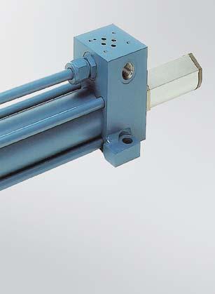
50 48 Air and Hydraulic Cylinders NFPA Industrial Type AVENTICS Corporation POWERMASTER PPT PNEUMATIC & PHT HYDRAULIC CYLINDERS STANDARD CYLINDER SPECIFICATIONS PNEUMATIC CUSHON (HEAD) PNEUMATIC CUSHION (CAP) HYDRAULIC OPERATING PRESSURES BY CYLINDER BORE SIZES (Max. PSI, Max. Duty Severe Service) Bore Size PHT-Hyd. PPT-Air 1 1/ /2 1500* / *With 5/8 rod, 1000 psi. MF1 & MF2 Maximum Operating Pressure is 1000 psi. For Double rod end cylinder pressure ratings, see page 68. Consult factory for specific applications at pressures higher than shown CYLINDER SPECIFICATIONS Duty 250 psi pneumatic PP, pre-lubricated. 250 to 1500 psi hydraulic PH Standards Meets or exceeds all J. I. C. and NFPA requirements. Bore Sizes 1-1/2-14 (standard), larger available. Piston Rods 5/8-5-1/2 (standard) Mounting 21 standard NFPA mountings. Temperature Range Standard Buna-N seals: -65 F to +200 F Optional Viton seals 15 F to +400 F (Consult factory for cylinder applications at extreme temperatures.) Ports NPTF dryseal tapered threads. Optional SAE straight thread ports available. (Flange ports available at extra cost.) Stroke Standard strokes furnished to nearest 1/8. Normal stroke tolerance +/- 1/16. Closer stroke tolerance available; consult factory. Rod End Threads Standard KK1 male and female threads plus KK2 oversize male thread. Other rod end style optional. Cushions Available for all bore sizes, at either or both ends. Piston Rods Case hardened to Rockwell C chrome-plated and finished to 15 microinches or better. (5/8 not case hardened) Tie Rods High tensile, 1144 stress proof steel Cylinder Tube Honed, steel tubing with chrome plated I.D. Double End Rod Available in many mounting styles to meet special needs.


.")

.")
51 Air and Hydraulic Cylinders NFPA Industrial Type AVENTICS Corporation 49 POWERMASTER PPT PNEUMATIC & PHT HYDRAULIC CYLINDERS CYLINDER SPECIFICATIONS Extra-long rod bearing provides for maximum support against side -loads including external misalignment. Marine-grade 660 bronze material has superior non-scoring properties and dimensional stability. Bearing is pilot fitted into the head assuring true concentricity and long bearing and seal life. Cartridge can be quickly and easily changed without special tools. Ductile iron is used in large bores with certain rod diameters. Pressure energized rod seal provides positive sealing with minimum friction drag. Self-adjusting seal in the Powermaster Pneumatic and U-cup/O-ring in the Powermaster Hydraulic coordinate operating pressures with sealing forces. Double Duty Twin Lip rod wiper provides dirt protection for the rod bearing and rod seal. External lip prevents entry of contaminants into the bearing area on in-stroke, and internal lip wipes rod on outstroke and serves as secondary seal. The standard materials are polyurethane, Buna-N and Viton. A metallic wiper is offered as an option (5/8 3 rod). Powermaster s self-aligning cushion design provides a positive sealing leakproof cushion with fast piston breakaway. The Powermaster Pneumatic cushioning consists of a floating cushion insert seal on both ends and the Powermaster Hydraulic has floating cushion bushing on the rod end with a floating metal insert seal on the cap end. This design provides for a maximum cushion effect with faster breakaway response. The AVENTICS Exact-a-just combination needle and check valve eliminates the need for separate ball checks (thus leaving a quadrant free for other possible use). Dent and corrosion resistant tubing. Steel tubing is honed to a 12 micro-inch, or better, finish, then chrome-plated for minimum friction and long seal life. (Chrome-plated I.D. tubing furnished for Powermaster Pneumatic). Pressure energized U-cup piston seals provide positive sealing with minimum friction. Standard Buna-N has an operating range of 65 F to +200 F with Viton available for high temperatures 15 F to +400 F.
52 50 Air and Hydraulic Cylinders NFPA Industrial Type AVENTICS Corporation POWERMASTER PPT PNEUMATIC & PHT HYDRAULIC CYLINDERS CYLINDER OPTIONS VITON SEALS Available for high temperature air service in a temperature range of 15 F to 400 F, and with many special hydraulic fluids. (Special fluids should be checked for compatibility with Viton). PISTON ROD OPTIONS Non-standard rod ends are available including rod and thread extensions, special threads and rod end machining, and additional wrench flats. (Catalog dimensional changes must be specified.) Optional rod materials for specific applications and environmental conditions which includes 303 and 17-4 PH stainless steel. METALLIC ROD WIPER Metal scraper available for the removal of tough/hardened matter adhering to piston rod. (Rod boots for exterior rod protection might also be considered.) PORT OPTIONS SAE straight thread ports are optional at no additional charge. Other standard size ports, oversize welded coupling ports and multiple ports are also available where design dimensions permit. STOP TUBE Internal stop tube is available for reducing excessive bearing loads and jackknifing conditions in long stroke push cylinders. (See page 113 for determining stop tube length required.) COMBINATION MOUNTING Additional cylinder mountings are available where design space permits. WATER SERVICE Model PW is available for water service and includes: electroless nickel plated head, cap, piston, and cushion parts when applicable. Standard Powermaster tube provides chrome-plated I.D. at no additional charge. Stainless steel piston rod is also recommended. EPOXY PAINT Available for additional exterior cylinder protection in corrosive environments. Painting includes one coat of Yellow Zinc Chromate Primer and one coat of Black Epoxy Enamel. TAPPED RETAINER PLATE Head retainer plate tapped for tie rods available when bolts or tie rod nuts are not permitted on head end. (Available for 1-1/2 6 bore sizes). EXTRA CHECK VALVE Available for faster breakaway response for cushioned cylinders. CUSHIONS (Exact-a-just ) Available for head, cap or both CONSULT FACTORY FOR OTHER OPTION REQUIREMENTS NOT SHOWN IN THIS CATALOG. CYLINDER BORE 1-1/ /2 3-1/ ZERO STROKE ADD PER INCH OF STROKE APPROXIMATE UNCRATED POWERMASTER WEIGHTS* *Weights based on standard (first) rod sizes.
.")
53 Air and Hydraulic Cylinders NFPA Industrial Type AVENTICS Corporation 51 POWERMASTER PPT PNEUMATIC & PHT HYDRAULIC CYLINDERS CYLINDER OPTIONS Oversize welded coupling ports are available where design and mounting dimensions permit. (Available on head end only in smaller bore sizes due to limited design space and mounting interference). AVENTICS offers a standard arrangement of thrust key mounting on the MS2, MS4 and MS7 Powermaster cylinders. This options eliminates the need for fitted bolts or external keys to carry the thrust load. The normal headplate is extended below the head surface of the cylinder and is fitted in a keyway milled into the mounting surface of the machine member. See drawings for details. Rod boots are available for additional rod protection from environmental conditions. The oil resistant cover of neoprene-coated nylon fabric is suitable for operation in ambient temperature range of 45 F to 220 F. Consult factory for higher temperature boot requirements. Stroke adjustment option is available for applications requiring a precise stroke or when infrequent stoke length adjustment is required in the retracted position. Maximum stroke adjustment varies by bore size and must be specified when ordering. Cushioning is not available on the cap end with this design. Upon request, we can supply most name brand switches, such as Balluff Strokemaster, P & F low profile, Stroke to Go low profile, NAMCO and others. CAUTION THESE UNITS ARE NOT INTENDED TO BE USED AS A FINAL SAFETY DEVICE 36 POSITON INDICATOR Proximity Position Indicator Switches are available for most mounting styles and rod sizes of Powermaster cylinders. These switches are mounted in the head and cap ends to confirm the extended or retracted position of the piston. The switches are actuated by the cushion bushing on the head end and the cushion spear on the cap end. (NOTE: If cap cushioning is required in the 1-1/2, 2 and 2-1/2 bore PP and PH Powermaster cylinder, proximity switches cannot be used on the cap end.) No linkage or external actuator is required. Switches can be assembled in the cylinder head, cap, or rear cap face. The switches are not sensitive to vibration and are suitable for most environments. Switch height is less than four inches; for critical dimensions, contact factory. SENSING DISTANCE End sensing of.090 (2.25mm) to.110 (2.76mm) when using a ferrous actuator approximately equal the area of the end. The differential (hysteresis) is approximately 1/2 of the sensing range. The GO Switch is not a reed switch. CONTACT RATING 2AMP at 240 VAC (CSA and UL approved) 50mA at 24 VDC (CSA only) CONTACT ARRANGEMENT Available in Single Pole, Double Throw. TEMPERATURE RANGE Tested to 22 F to +250 F. Impervious to most environments. Recognized by UL at 104 F (40 C) maximum. GO is a trademark of General Equipment Manufacturing Company, Inc.

54 52 Air and Hydraulic Cylinders NFPA Industrial Type AVENTICS Corporation POWERMASTER PPT PNEUMATIC & PHT HYDRAULIC CYLINDERS EXTENDED KEY PLATE AVENTICS offers a standard arrangement of thrust key mounting on the MS2, MS4 and MS7 PowerMaster cylinders. This option eliminates the need for fitted bolts or external keys to carry the thrust load. The normal headplate is extended below the head surface of the cylinder and is fitted in a keyway milled into the mounting surface of the machine member. See drawings for details. MS2 MS4 BORE E FA LH PA PC PD PF PG MS NOTE: 1.Use mounting bolt.06 smaller in diameter than hole size. 2.Fitted bolts or dowel pins are not needed with the trust key headplate. 3.All dimensions not shown are NFPA standard. POWERMASTER PHT & HHT HYDRAULIC CYLINDERS AVAILABLE PORTS FOR PHT SERIES CYLINDERS AVAILABLE PORTS FOR HHT SERIES CYLINDERS BORE SIZE (inches) SAE NPTF PIPE THD BSPP PARALLEL THD BSPT TAPER THD METRIC STRAIGHT THD ISO METRIC THD BORE SIZE SAE (inches) NPTF PIPE THD BSPP PARALLE L THD SAE 4-BOLT FLANGE NOM. SIZE BSPT TAPER THD METRIC STRAIGHT THD ISO METRIC THD 1 #4 1/4 1/4 1/4 M14 X #6 3/8 3/8 3/8 M14 X #6 3/8 3/8 3/8 M14 X 1.5 M14 X #6 3/8 3/8 3/8 M14 X 1.5 M14 X #8 1/2 3/8 3/8 M22 X 1.5 M22 X #8 1/2 1/2 1/2 M22 X 1.5 M22 X #8 1/2 1/2 1/2 M22 X 1.5 M22 X #12 3/4 1/2 1/2 M26 X 1.5 M27 X #8 1/2 1/2 n/a 1/2 M22 X 1.5 M22 X #8 1/2 1/2 * 1/2 1/2 M22 X 1.5 M22 X #8 1/2 1/2 * 1/2 1/2 M22 X 1.5 M22 X #12 3/4 3/4 ** 1/2 3/4 M27 X 2 M27 X 2 4 #12 3/4 3/4 1/2 3/4 M27 X 2 M27 X 2 5 #12 3/4 3/4 *** 1/2 3/4 M27 X 2 M27 X 2 6 # /4 1 M33 X 2 M33 X 2 7 #20 1-1/4 1-1/ /4 M42 X 2 M42 X 2 8 #24 1-1/4 1-1/2 1-1/4 1-1/2 M48 X 2 M48 X 2 Size 1/2 on 6 bore (4 rod) and 7 bore (5 rod); Size 1 on 8 bore (5-1/2 rod). *Cap only **Not available on 3-1/4 bore (2 rod). ***Not available on 5 bore (3-1/2 rod).


55 Air and Hydraulic Cylinders NFPA Industrial Type AVENTICS Corporation 53 POWERMASTER PPT PNEUMATIC & PHT HYDRAULIC CYLINDERS D DOUBLE ROD CYLINDER Bore sizes 1-1/2 6.. page 54 Bore sizes 8 14 ME3 ME4 MOUNTING INDEX HEAD SQUARE FLANGE Bore sizes page 54 MF1 CAP SQUARE FLANGE Bore sizes page 54 HEAD RECTANGULAR FLANGE Bore sizes 1-1/2 6.. page 56 MF2 CAP RECTANGULAR FLANGE Bore sizes 1-1/2 6.. page 56 MF5 HEAD SQUARE FLANGE Bore sizes 1-1/2 6.. page 56 MF6 CAP SQUARE FLANGE Bore sizes 1-1/2 6 page 56 MP1 MP3 CAP FIXED CLEVIS Bore sizes 1-1/2 14 page 58 MP2 CAP FIXED EYE Bore sizes 1-1/2 14.page 58 MP4 CAP DETACHABLE CLEVIS Bore sizes 1-1/2 8.. page 58 CAP DETACHABLE EYE Bore sizes 1-1/2 8.. page 58 MS1 SIDE END ANGLES Bore sizes 1-1/2 6.. page 60 Bore sizes 8 14 MS2 SIDE LUGS CENTERLINE LUGS Bore sizes 1-1/2 6..page 62 MS3 Bore sizes 1-1/2 6.. page 62 Bore sizes 8 14 MS4 MX0 SIDE TAPPED Bore sizes 1-1/2 14.page 62 NO MOUNTINGS Bore sizes 1-1/2 14.page 62 MS7 SIDE END LUGS Bore sizes 1-1/2 6..page 60 Bore sizes 8 14 MT1 HEAD TRUNNION Bore sizes 1-1/2 6.. page 64 MT2 CAP TRUNNION Bore sizes 1-1/2 6.. page 64 Bore sizes 8 14 MT4 INTERMEDIATE FIXED TRUN- NION Bore sizes 1-1/2 6..page 64 Bore sizes 8 14 MU3 UNIVERSAL CLEVIS Bore sizes 1-1/2 6.. page 58 MX1 MX2 TIE ROD EXTENDED Bore sizes 1-1/2 6.. page 66 Bore sizes 8 14 MX3 MX4


56 54 Air and Hydraulic Cylinders NFPA Industrial Type AVENTICS Corporation POWERMASTER PPT PNEUMATIC & PHT HYDRAULIC CYLINDERS DOUBLE ROD CYLINDER HEAD SQUARE FLANGE MOUNT CAP SQUARE FLANGE MOUNT D DOUBLE ROD CYLINDER 1-1/2-4 *8-14 Bores only **1-1/2-6 Bores only ME3 HEAD SQUARE FLANGE 8-14 ME4 CAP SQUARE FLANGE 8-14
57 Air and Hydraulic Cylinders NFPA Industrial Type AVENTICS Corporation 55 POWERMASTER PPT PNEUMATIC & PHT HYDRAULIC CYLINDERS TABLE 1 Dimensions affected by rod diameter BORE IN MM ROD V W WF Y XN ZB ZJ ZL ZM DOUBLE ROD END CYLINDER HEAD SQUARE FLANGE MOUNT CAP SQUARE FLANGE MOUNT Double rod end cylinders are available in every mounting style except clevis or pin type. For dimensions on specific mounting styles, consult the page showing the required mounting. On cylinders where the rod ends are not the same, be sure to specify where each rod end is located in relation to the mounting requirement. Note that bore sizes 1-1/2 6 have square retainers, and the same square size as the head on both ends. One of theses retainers is held in place by the tie rod nuts and therefore cannot be removed without loosening the tie rods bore cylinders have retainers to the XN dimension. Solid head and cap flanges mounts are some of the strongest, most rigid methods of mounting cylinders. The head flange type is best in a tension application. The cap flange type is best in a thrust application. Double rod end cylinders are available with fixed non-adjustable cushion on both ends. Head and cap flange cylinders are available with fixed non-adjustable cushion on the head end with Exact-a-just cushion on the cap or blind end. Double Rod End Pressure Rating- See page 68 Rod end options are shown on page 52a. TABLE 2 Dimensions not affected by rod diameter BORE EB EE E F G J K P AA DD THD IN BOLT NPTF LB LD TE

58 56 Air and Hydraulic Cylinders NFPA Industrial Type AVENTICS Corporation POWERMASTER PPT PNEUMATIC & PHT HYDRAULIC CYLINDERS MF1 HEAD RECTANGULAR FLANGE 1-1/2-6 MF2 CAP RECTANGULAR FLANGE 1-1/2-6 MF5 HEAD SQUARE FLANGE 1-1/2-6 MF6 CAP SQUARE FLANGE 1-1/2-6
59 Air and Hydraulic Cylinders NFPA Industrial Type AVENTICS Corporation 57 POWERMASTER PPT PNEUMATIC & PHT HYDRAULIC CYLINDERS TABLE 1 Dimensions affected by rod diameter BORE IN MM ROD V W Y ZB ZF ZJ FLANGE MOUNTS Flange mounts are one of the strongest, most rigid methods of mounting. With this type of mount, there is little allowance for misalignment, so when long strokes are required, the free end opposite the mounting should be supported to prevent sagging and possible binding of the cylinder. Blind or cap end mounts are best for thrust load applications, and rod or head end mounts are best in tension applications. If an application exceeds the rectangular flange rating, a solid head or cap flange mount (ME3) or (ME4) is available. (Refer to page 54). When a less rigid mount can be used and the cylinder can be attached to a panel or bulkhead, an extended tie rod mount could be considered. Note: The maximum hydraulic pressure rating for MF1 and MF2 mounts in 1000 psi. NOTE: Available with fixed cushioning on the rod end and Exact-a-just cushioning on the blind end. Removable bearing retainer is not available in the 1-1/2 6 bore cylinders. The bearing retainer plate is the same as the E dimension for 1-1/2 6 bore sizes. Rod end options are shown on page 52a. TABLE 2 Dimensions not affected by rod diameter BORE IN E F G J K P R EE NPTF FB BOLT LB TF UF

60 58 Air and Hydraulic Cylinders NFPA Industrial Type AVENTICS Corporation POWERMASTER PPT PNEUMATIC & PHT HYDRAULIC CYLINDERS FIXED & DETACHABLE CLEVIS MOUNTS AND UNIVERSAL CLEVIS MOUNT MP1 CAP FIXED CLEVIS 1-1/2 14 MP3 CAP FIXED EYE 1-1/2 8 *8-14 Bores only **1-1/2-6 Bores only MP2 CAP DETACHABLE CLEVIS 1-1/2 8 MP4 CAP DETACHABLE EYE 1-1/2 8 MP3, MP4 Cap *8 Bore only **1-1/2-6 Bores only MU3 UNIVERSAL CLEVIS 1-1/2 6
61 Air and Hydraulic Cylinders NFPA Industrial Type AVENTICS Corporation 59 POWERMASTER PPT PNEUMATIC & PHT HYDRAULIC CYLINDERS TABLE 1 Dimensions affected by rod diameter BORE IN MM ROD V W WF Y XC XD XH XN ZC ZD ZH ZJ FIXED & DETACHABLE CLEVIS MOUNT & UNIVERSAL CLEVIS MOUNT The Clevis or Pin mounted cylinder is probably the most widely used of all mounts. For short stokes, medium or small cylinder applications, the clevis mounts are recommended. If this mount is applied where stroke requirements cause the overall length to be excessive, the Cap Trunnion mount can be used. Pivot mounts must always be used with a pivot type rod end attachment. NOTES: Available with fixed, nonadjustable cushion on the rod end and Exact-a-just cushioning on the blind or cap end only The bearing retainer plate is the same as the E dimension for 1-1/2 6 bore sizes and the XN dimension for the 8 14 bore sizes. Rod end options are shown on page 52a. MP1 and MP2 mounts include pivot pin. MU3 does not include pivot pin. TABLE 2 Dimensions not affected by rod diameter BORE EW/ EE E F G J K L M P CD CW CX IN CB NPT EX EP LA LB LE LR MA MB MR For MP2, MP4 at 8 bore, F=1.00 at rear flange only.


62 60 Air and Hydraulic Cylinders NFPA Industrial Type AVENTICS Corporation POWERMASTER PPT PNEUMATIC & PHT HYDRAULIC CYLINDERS MS1 SIDE END 1-1/2 14 SIDE END LUG & SIDE END ANGLE MOUNT *8-14 Bores only **1-1/2-6 Bores only MS7 SIDE END LUGS 1-1/2 14 *8-14 Bores only **1-1/2-6 Bores only
63 Air and Hydraulic Cylinders NFPA Industrial Type AVENTICS Corporation 61 POWERMASTER PPT PNEUMATIC & PHT HYDRAULIC CYLINDERS TABLE 1 Dimensions affected by rod diameter BORE MM IN ROD V W WF Y XA XE XN ZA ZB ZE ZJ TABLE 2 Dimensions not affected by rod diameter BORE IN E F G J K P R AA AB BOLT AH AL AO AT EB EE BOLT NPTF SIDE END LUG AND ANGLE MOUNTS The side end mounts lend themselves to easy mounting and replacement. They also permit side by side mounting in confined areas. As with the side lug mounts, proper use will place the bolts in simple shear or tension without any compound stresses. The alignment is critical to maximum service life. When specifying these mounts, carefully check the distance between the rod and lug or angle to determine if there is sufficient clearance for the rod end attachment. It may be necessary to add a plain rod extension to move the treaded rod end out beyond the lug. These mounts require the loosening of the tie rods to remove the rod gland for bore sizes 1-1/2 6. NOTE: Available with fixed nonadjustable cushion on the rod end and standard Exact-a-just cushion on the cap end only. The bearing retainer plate is the same as the E dimension for the 1-1/2 6 bore sizes and the XN dimension for the 8 14 bore sizes. Rode end options are shown on page 52a. For double rod cylinders 1-1/2 thru 8 bore, add 1/2, for 10 & 12 bore, add 1/4, for 14 bore add 1/2. EL EO ET LB RA SA SE


64 62 Air and Hydraulic Cylinders NFPA Industrial Type AVENTICS Corporation POWERMASTER PPT PNEUMATIC & PHT HYDRAULIC CYLINDERS MS2 SIDE LUGS 1-1/2 14 SIDE & CENTERLINE LUG MOUNTS AND SIDE MOUNTS *8-14 Bores only **1-1/2-6 Bores only MS3 CENTERLINE LUGS 1-1/2 14 MS4 SIDE TAPPED 1-1/2 14 MX0 NO MOUNTING 1-1/2 14 Same as MS4 less mounting holes
65 Air and Hydraulic Cylinders NFPA Industrial Type AVENTICS Corporation 63 POWERMASTER PPT PNEUMATIC & PHT HYDRAULIC CYLINDERS BORE IN TABLE 1 Dimensions affected by rod diameter MM ROD V W WF Y XN XS XT ZB ZJ SIDE AND CENTERLINE LUG MOUNTS The side or lug mounted cylinder provides a fairly rigid mount. These type mounts can tolerate a slight amount of misalignment when the cylinder is at full stroke, but as the piston moves toward the blind end, the tolerance for misalignment decreases. It is important to note that if the cylinder is used properly the mounting bolts are either in simple shear or tension without any compound stresses. NOTES: When specifying an MS2 mount with ports in the 2 or 4 quadrant, be sure there is sufficient clearance between the port fitting and the lug to insert a bolt or cap screw into the lug. Available with fixed non-adjustable cushioning on the rod and Exact-a-just cushioning on the blind end. The bearing retainer plate is the same as the E dimension for 1-1/2 6 bore sizes and the XN dimension for the 8 14 bore sizes. Rod end options are shown on page 52a For double rod cylinders 1-1/2 thru 8 bore, add 1/2 ; for 10 & 12 bore, add 1/4 ; for 14 bore add 1/2. BORE IN TABLE 2 Dimensions not affected by rod diameter E F G J K P DT EE NPTF LB NT THD SB BOLT SN SS ST SU SW SX SY TN TS US


66 64 Air and Hydraulic Cylinders NFPA Industrial Type AVENTICS Corporation POWERMASTER PPT PNEUMATIC & PHT HYDRAULIC CYLINDERS TRUNNION MOUNTS MT1 HEAD TRUNNION 1-1/2 14 *8-14 Bores only **1-1/2-6 Bores only The XG and XJ dimensions for MT1 and MT2 mounts are longer than NFPA standard. MT2 CAP TRUNNION 1-1/2 14 *8-14 Bores only **1-1/2-6 Bores only The XG and XJ dimensions for MT1 and MT2 mounts are longer than NFPA standard. MT4 INTERMEDIATE FIXED TRUNNION 1-1/2 14 *8-14 Bores only **1-1/2-6 Bores only
67 Air and Hydraulic Cylinders NFPA Industrial Type AVENTICS Corporation 65 POWERMASTER PPT PNEUMATIC & PHT HYDRAULIC CYLINDERS TABLE 1 Dimensions affected by rod diameter BORE IN MM ROD V W WF Y XG ZB XI MIN XJ XN ZJ TABLE 2 Dimensions not affected by rod diameter BORE SIZE E F G J K P BD EE NPTF LB *TD TRUNNION MOUNTS All trunnion mounted cylinders need a provison on both ends for pivoting. These types of cylinders are designed to carry shear loads and the trunnion and pivot pins should be carried by bearings that rigidly held and closely fit for the entire length of the pin. Head or rod end trunnions should be carefully applied to either short strokes or to applications where the weight of the cylinder falls vertically below the pin. NOTES: Available with fixed nonadjustable cushion on the rod end and standard Exact-a-just cushion on the cap end only. Specify the XI dimension when ordering MT4 Intermediate Fixed Trunnion mounts. If not specified, the trunnion will be located at the center of the tube. The XG and XJ dimensions for MT1 and MT2 mounts are not NFPA Standard. The bearing retainer plate is the same as the E dimension for bore sizes 1-1/2 6 and the XN dimension for 8 14 bore sizes. For rod end options see pg 52a. TL TM UB UM UT Air PP Oil PH

 **1-1/2-6 Bores only MX3 TIE RODS")

68 66 Air and Hydraulic Cylinders NFPA Industrial Type AVENTICS Corporation POWERMASTER PPT PNEUMATIC & PHT HYDRAULIC CYLINDERS MX1 TIE RODS EXTENDED BOTH ENDS 1-1/ Bore *8-14 Bores only (XN See above) **1-1/2-6 Bores only MX2 TIE RODS EXTENDED CAP END ONLY 1-1/2 14 *8-14 Bores only (XN See above) **1-1/2-6 Bores only MX3 TIE RODS EXTENDED HEAD END ONLY 1-1/2 14 *8-14 Bores only (XN See above) **1-1/2-6 Bores only MX4 TIE RODS EXTENDED HEAD END ONLY 1-1/2 14 *8-14 Bores only (XN See above) **1-1/2-6 Bores only
69 Air and Hydraulic Cylinders NFPA Industrial Type AVENTICS Corporation 67 POWERMASTER PPT PNEUMATIC & PHT HYDRAULIC CYLINDERS TABLE 1 Dimensions affected by rod diameter BORE MM IN ROD V W WF Y XN ZB ZJ ZT * * * For these or larger size rods on 8 and 10 bores, consult factory before ordering. BORE IN EXTENDED TIE ROD MOUNTS Tie rod and flange mounts are basically the same except that the tie rods are extended and used to mount the cylinder. To prevent misalignment, sagging, or binding of the cylinder when long strokes are required, the free end of the cylinder should be supported. For thrust load applications, blind or cap end tie rod extensions are best. For tension load applications, rod or head end extensions are best. Tie rod mounts are suited for many applications however, it should be noted that they are not as rigid as the flange mount. NOTES: Available with fixed non-adjustable cushion on the rod end and standard Exact-a-just cushion on the cap only. The bearing retainer plate is the same as the E dimension for 1-1/2 6 bore sizes and the XN dimension for the 8 14 bore sizes. For rod end options see page 52a. TABLE 2 Dimensions not affected by rod diameter E F G J K P AA BB DD THD EE NPTF LB
70 68 Air and Hydraulic Cylinders NFPA Industrial Type AVENTICS Corporation POWERMASTER PPT PNEUMATIC & PHT HYDRAULIC CYLINDERS EXAMPLES (A) 2 x 10 C-MP1-PHT-C; 5/8 Rod, 7/16-20 M. Threads MOUNTINGS Head Square ( ) ME3 Cap Screws ( ) ME4 Head Rectangular Flange (1-1/ ) MF1 Cap Rectangular Flange (1-1/ ) MF2 Head Square Flange (1-1/ ) MF5 Cap Square Flange (1-1/ ) MF6 Cap Fixed Clevis MP1 Cap Detachable Clevis MP2 Cap Fixed Eye MP3 Cap Detachable Eye MP4 Side End Angles MS1 Side Lug MS2 Center Line Lug MS3 Side Tap MS4 Side End Lug MS7 Head End Trunnion MT1 Cap End Trunnion MT2 Intermediate Fixed Trunnion (specify XI) MT4 Universal Clevis MU3 Tie Rod Mounting MX0, 1, 2, 3, 4 * Double Rod End (Example MDE3) (Specify only when required, available in most mountings. 1-1/2, 2, 2-1/2 bore cylinders with the maximum oversize rod and head cushion have no head cushion adjustment or check valve bypass. These models are not recommended for double end application.) HOW TO ORDER (B) 4 x 36 Effective Stroke, C-MP1-PHT-C 1-3/8 rod, 1-14 male Threads, 4 Stop Tube A = STD + 1, W = STD + 1/2, Epoxy Paint Proximity Location #4 Head and Cap 2 x 10 C M*P1 PHT C 5/8 ROD, 7/16-20 M. Threads Bore Size (Specify) Stroke (Specify) Cushion Head End (Leave blank if non-cushion head end) Mountings Series: PHT-Hydraulic (Low Pressure) PPT-Pneumatic Cushion Cap End (Leave blank if non-cushion cap end) *PRESSURE RATINGS FOR DOUBLE ROD END POWERMASTER CYLINDERS OPTIONS PSI Not Available Seals-- Standard, Viton, other PSI 750 PSI Piston Rod Stud PSI 750 PSI Rod Extension ( W Dimension) Thread Extension ( A Dimension) Stop Tube (Specify Effective Stroke) + inches of stop tube Piston Rod Material (Stainless Steel) PSI 750 PSI 750 PSI 750 PSI 750 PSI 750 PSI Port Location if other than standard #1 location PSI 750 PSI Cushion Location if other than standard #2 location PSI Not Available Water Service PSI 750 PSI Mixed Mountings PSI 750 PSI Epoxy Paint Additional Ports SAE O-ring Straight Thread Ports Additional Cushion Adjustment Screws Oversized Ports Stroke Adjuster in Cap Moveable Center Trunnion (MT4) Special Items as Required PSI 750 PSI 750 PSI 750 PSI 675 PSI 750 PSI 750 PSI 750 PSI BORE SIZE ROD SIZE CUSHION ROD END OR NON- CUSHION Rod Size (Specify) CUSHION BOTH ENDS OR EXT ,000 PSI 750 PSI ,000 PSI 1,000 PSI PSI 450 PSI ,000 PSI 500 PSI ,000 PSI 1,000 PSI PSI 250 PSI ,000 PSI 500 PSI ,000 PSI 1,000 PSI ,000 PSI 1,000 PSI PSI Not Available ,000 PSI 1,000 PSI ,000 PSI 1,000 PSI ,000 PSI 1,000 PSI PSI Not Available ,000 PSI 1,000 PSI ,000 PSI 1,000 PSI ,000 PSI 1,000 PSI ,000 PSI 1,000 PSI Thread Size (Specify) BORE SIZE ROD SIZE Type Threads M-Male F-Female CUSHION ROD END OR NON- CUSHION CUSHION BOTH ENDS OR EXT PSI Not Available PSI 450 PSI PSI 500 PSI PSI 500 PSI PSI 500 PSI PSI 500 PSI PSI 500 PSI PSI Not Available PSI 300 PSI PSI 400 PSI PSI 400 PSI PSI 400 PSI PSI 400 PSI PSI Not Available PSI 250 PSI PSI 250 PSI PSI 250 PSI PSI 250 PSI PSI Not Available PSI 250 PSI PSI 250 PSI PSI 250 PSI PSI 250 PSI
71 Air and Hydraulic Cylinders NFPA Industrial Type AVENTICS Corporation 69 This page is intentionally blank.
72 70 Air and Hydraulic Cylinders NFPA Industrial Type AVENTICS Corporation POWERMASTER PPT PNEUMATIC & PHT HYDRAULIC CYLINDERS 1-1/2 14 BORES INSTALLATION AND SERVICE INFORMATION Approximate Uncrated Powermaster Weights (lbs.)* (Air & Hydraulic Models) CYLINDER BORE ZERO STROKE ADD PER INCH OF STROKE 1-1/ /2 3-1/ *Weights based on standard (first) rod sizes. WARNING Read and follow warnings and directions as listed on the inside back cover of this catalog prior to performing any service or installation. INSTALLATION For outline dimensions and other considerations in mounting the Powermaster, see pages 54 and 67. Before plumbing the cylinder, all lines in the system should be flushed to remove any contamination. To prevent corrosion and accumulation of foreign matter in the air cylinder, a 10 MICRON or better filter should be installed in the supply line to the cylinder control valve. A very important consideration in mounting the Powermaster cylinder is keeping the cylinder thrust as close as possible to the centerline of the piston rod and free of misalignment or side loading. Off-center thrust or side loads decrease the normal life of the rod bearing and seals and can cause binding in the cylinder or linkage. Forcing rod, clevis pins, or mounting bolts into position indicates that the cylinder is not properly aligned, and permanent damage may result for such installation. Side End Angles (MS1), Side Lugs (MS2), Centerline Lugs (MS3) and Side End Lugs (MS7): After a cylinder with one of these mountings has been aligned, key or pin it to its support. Properly located shear keys or pins will absorb the major portion of the shear load that can develop in the bolts that fasten the cylinder to its support. Always use high-tensile steal bolts to fasten the cylinder. Head Rectangular Flange (MF1), Cap Rectangular Flange (MF2), Head Square Flange (MF5 & ME3), and Cap Square Flange (MF6 & ME4): A flange-mounted cylinder can be centered by using the gland in the cylinder head as a pilot. After mounting and alignment, the cylinder should be dowelled to its supports to keep it from shifting. For installations that use maximum operating pressures or have high shock loads, a square flange is recommended. Head Trunnion (MT1), Cap Trunnion (MT2), and Intermediate Fixed or Movable Trunnion (MT4): Install a trunnion-mounted cylinder in rigid and accurately aligned pillow blocks. These blocks should be well lubricated at all times. Since trunnion pins are designed for shear loads only, provide linkage with a suitable pivot for connection to the rod end of the cylinder. STANDARD SPECIFICATIONS Duty: 250 psi Pneumatic, psi Hydraulic (see chart) Standards: Meet or exceeds all J.I.C. and NFPA requirements Bore Sizes: 1-1/2 14 (standard) Piston Rods: 5/8 5-1/2 (standard) Mountings: 21 standard NFPA mountings. Temperature Range: -65 F to +200 F (Buna N Standard seals) Optional Viton seals for 15 F to +400 F and many fluids which require chemical resistance. HYDRAULIC OPTERATING PRESSURES BY CYCLINDER BORE SIZES BORE SIZE MAX. PSI, MAX. DUTY, SEVERE SERVICE 1-1/ /2* 3-1/ ,500 1,500 1, * for 5/8 rod, 1000 psi Fixed Clevis (MP1), Detachable Clevis (MP2) and Universal Clevis (MU3): In the installation of a clevis-mounted cylinder, the centerline of the pivot pin in the rod end linkage must be parallel with the centerline of the clevis pin in the cap end of the cylinder. A universal clevis mount automatically compensates for 5 to 10 degrees of misalignment in any direction. Never allow the cylinder head or cap to stop the piston at the end of its stroke. Either provide external stops to prevent the piston from bottoming or use a cylinder with built-in cushioning. A cushioned cylinder will stop the piston just before it reaches the end of its stroke. Under certain conditions of load, external stops may be required to supplement the cylinder cushioning. OPERATION The standard Powermaster pneumatic cylinder has a maximum operating pressure of 250 psi, and the hydraulic cylinder a maximum of psi at a temperature range of 65 F to +200 F. For operating temperatures above or below this range, cylinders with special packing and seals are required. Air pressure supplied to the cap-end port moves the piston rod to its extended position. Pressure supplied to the head end port moves the piston rod to its retraced position. See page 107 for forces developed by each cylinder. ADJUSTMENT A noncushioned cylinder requires no further adjustment after it has been installed and properly aligned. A cushioned cylinder, after installation and alignment, must be adjusted to obtain the degree of cushioning desired. An adjustment is provided by a screw-type needle and check valve in either or both ends of the cylinder. This Exact-a-just valve controls the rate at which trapped air or fluid is allowed to meter from the end of the cylinder when the piston is near the end of its stroke. Turn the needle valve clockwise to increase the amount of cushioning and counter-clockwise to decrease cushioning. To obtain the most effective cushioning, final adjustment must be made while the cylinder is operating under normal conditions at normal operating pressure.
73 Air and Hydraulic Cylinders NFPA Industrial Type AVENTICS Corporation 71 POWERMASTER PPT PNEUMATIC & PHT HYDRAULIC CYLINDERS 1-1/2 14 BORES MAJOR REPAIR, MAINTENANCE & TESTING GENERAL MAINTENANCE AND REPAIR RECOMMENDATIONS Maintenance periods should be scheduled in accordance with frequency of use and working environment of the cylinder. All cylinders must be visually inspected for wear and given an in system operating performance and leakage test at least once a year. If these visual observations indicate cylinder repair is required, the cylinder must be removed, repaired and tested. A major overhaul is recommended at one million cycles. However, where frequency of use is such that it would require more than two years to obtain one million cycles, the cylinder must be overhauled at the two year period. When it is determined that the cylinder requires a major repair as a result of the one million cycles, one year routine inspection, or the two year service period has elapsed, the device must be disassembled, cleaned, inspected, parts replaced as required, rebuilt and tested for leakage, and proper operation prior to installation. Refer to MAJOR REPAIR, MAINTENANCE INSTRUCTION, and TEST PROCEDURES. MAJOR REPAIR AND MAINTENANCE INSTRUCTION. Always exhaust or drain the pressure from the system before performing any service work. Disconnect lines from head and cap ports of cylinder. Completely disassemble the cylinder using the exploded and assembly views as reference. No special tools are required except internal snap ring pliers. The piston rod assembly consisting of rod, piston and head cushion bushing (where used) are torque and secured at the factory and are not to be disassembled (cylinders built prior to 1985 utilized piston nut). After disassembling the cylinder, wash all metal parts in a non-flammable solvent. Rinse each part thoroughly and blow dry with a low pressure air jet. Arrange the parts on a clean surface. Examine each part carefully. Replace all rubber parts and other worn or damaged parts. The use of REPAIR KITS is strongly recommended. Particular attention should be given to the rod bearing (5a) since cylinder leakage can result from a worn bearing. A scored or rough rod bearing might damage the piston rod and subsequently, the rod packing. Rod cartridge kits are available with or without the rod bearing. An excellent feature of the POWERMASTER Cylinder is easy replacement of the rod cartridge (5) without loosening the tie rods. On most cylinders with the bore sizes from 1-1/2-6 inches, remove the screws and washers (1 & 2) and retainer plate (4a). For all cylinders with bore sizes 8-14, remove screws (3) and retainer plate (4b). The rod cartridge is easily removed from the cylinder hear. To facilitate removal, a screwdriver can be used to pry in the external groove. REASSEMBLY The procedure for reassembly is essentially the reverse of disassembly. However, the following exceptions should be noted: 1. All O-rings should be well coated with Cylinder Lube grease for air cylinders or the hydraulic fluid used in the application for hydraulic cylinders, as they are installed in their respective grooves and prior to reassembly with the mating part. Care must be taken when assembling O-rings and packings that they are not damaged, as this will cause leakage. 2. Reassemble the cylinder using the exploded and assembly views as reference. Pneumatic Only: As the assembly proceeds, lubricate the piston seals, cushion seals, rod seal, tube and tube seals with Cylinder Lube grease. Pay particular attention to the installation of the cushion kit (ref. 11 &19) to insure that the tapered rubber surface marked THIS SIDE UP faces to the inside (piston side) of the cylinder. Hydraulic Only: Lubricate inside diameter of cylinder tube and piston rod, plus all seals, with hydraulic fluid used in cylinder application. The hydraulic fluid specified for use in the cylinder is the only lubricant to be used in assembly. 3. Tie rod threads should be well lubricated to allow tightening the nuts evenly for proper pre-stressing. To avoid twisting of the tie rods during tightening, hold with vise grip or clamp. To assure equal pre-stressing of the tie rods, first turn on nuts even and snug to align assembly, then the nuts are to be tightened alternately. For proper tie rod pre-stressing, they should be torque as recommended. The specific torque value is determined by the diameter of the tie rod. For lubricated tie-rod threads, these torque values are: CYL. BORE SIZE TIE ROD DIA. TORQUE-LUBRICATED POUNDS FOOT 1-1/2 1/ / /2 5/ /4 3/ / & 6 1/ /8 90 TESTING: After the cylinder has been completely reassembled, it should be tested, either on a test bench or in the regular installation. TEST PROCEDURES:(see maximum psi/style). The cylinder should be tested for cushioning, travel and leakage. A. Cushioning (if applicable) 1. Turn both cushioning screws clockwise all the way in. 2. Cycle cylinder a few times by alternating supply pressure to head & cap ports. 3. Apply supply pressure to the head port. Rod should retract, decelerate and may stop before completion of stroke. 4. Apply supply pressure to the cap port. Rod should extend, decelerate and may stop before completion of stroke. B. Travel and Leakage 1. Turn the cushioning screws counterclockwise one (1) full turn. 2. Apply supply pressure to the head port. Rod should retract smoothly without binding. Cylinder should retract, has less cushioning and make full stroke + or Check leakage at cap port, 30cc/min. leakage permitted. Check leakage around rod seal. No leakage permitted. 3. Apply supply pressure to the cap port. Rod should extend smoothly without binding. Cylinder should have less cushioning and make full stroke + or Check leakage at head port, 30cc/min. leakage permitted. 4. Return piston rod to retract position by applying supply pressure to head port. Remove supply pressure and install cylinder in service if satisfactory. CUSHION ADJUSTMENT Turn the needle valve clockwise to increase the amount of cushioning and counter-clockwise to decrease cushioning. To obtain the most effective cushioning, final adjustment must be made while the cylinder is operating under normal conditions at normal operating pressure.


74 72 Air and Hydraulic Cylinders NFPA Industrial Type AVENTICS Corporation POWERMASTER PPT PNEUMATIC & PHT HYDRAULIC CYLINDERS POWERMASTER PPT PNEUMATIC CYLINDERS 1-1/2 14 BORES 1-1/2 through 6 bores 8 through 14 bores
75 Air and Hydraulic Cylinders NFPA Industrial Type AVENTICS Corporation 73 POWERMASTER PPT PNEUMATIC & PHT HYDRAULIC CYLINDERS REF. SERVICE INFORMATION POWERMASTER PPT PNEUMATIC, 1-1/2 14 BORES DESCRIPTION CUSHIONED BOTH ENDS CUSHIONED HEAD ONLY CUSHIONED CAP ONLY NON-CUSHIONED 1 SCREW, Cap (1-1/2-6 bores) WASHER, Lock (1-1/2-6 bores) SCREW, Socket Head Cap (8-14 bores) a PLATE, Retainer (1-1/2-6 bores) b PLATE, Retainer (8-14 bores) * CARTRIDGE, Rod Kit a BEARING, Rod b WIPER, Rod c PACKING, U Rod d O-RING, Backup e O-RING, Rod Bearing f RING, Backup NUT, Tie Rod Lock 7 HEAD * CUSHION, Needle Valve Kit a VALVE, Exact-a-just Needle & Check (includes Ref. 8) b O-RING, Needle Valve * PISTON & TUBE Seal Kit a O-RING, End Cover b O-RING, Head Cushion Bushing c O-RING, Piston Bearing d SEAL, Piston e RING, Piston Backup RING, Head Cushion Retaining SEAL, Head Cushion Kit NUT, Piston Retaining (Not shown - not used after 1984) PISTON 14 BUSHING, Head Cushion ROD, Female Piston a ADAPTER, Male Piston Rod (when required) TUBE, Cylinder TIE ROD RING, Cap Cushion Retaining * SEAL, Cap Cushion Kit CAP *Recommended spare parts to be retained in stock at all times. See REPAIR KITS below. On 8 14 bores, 8 are always required. On 1-1/2 6 bores, 4 are normally required, but may sometimes replace Ref. No. 1 & 2 on some mounting styles. REPAIR KITS Repair parts included in the following repair kits are available only in kit form. Kits should be ordered by kit part numbers plus cylinder part number when possible. Some kits may have an excess of parts not used in some cylinder models. Discard these parts or keep for later use. Other parts not included in repair kits must be ordered separately by reference number, description, and cylinder part number. Rod Cartridge Kit (with Rod Bearing) Buna N With Urethane Rod Viton Rod Wiper (std.) Diameter Part Number Part Number 0.63" R R " R R " R R " R R " R R " R R " R R " R R " R R " R " R R " R Includes Ref. items: 5a, 5b, 5c, 5d, 5e & 5f Piston & Tube Seal Kit Bore BUNA N VITON Size Part Number Part Number 1.50" R R " R R " R R " R R " R R " R R " R R " R R " R R " R R " R R Includes Ref. Items 9a, 9c, 9d & 9e. Rod Seal Kit (less Rod Bearing) Head Cushion Seal Buna N With Urethane Rod Viton Buna N* Wiper (std.) Part Number Part Number Part Number R R R R R R R R R R R R R R R R R R R R R R R R R R * Buna N rubber Includes Ref. items 5b, 5c, 5d, 5e & 5f For high-temp. operaconsult the factory. Cap Cushion Seal BUNA N* Part Number R R R R R R R R R R R *Buna N rubber (Ref. 19) For high-temperature operation, consult factory Cushion Needle Valve Assemblies (Exact-a-just ) Part Bore Sizes Number R ", 2", 2.5" Buna- R ", 4", 5" Buna- R " thru 14" Buna-N R ", 2", 2.5" Viton R ", 4", 5" Viton R " thru 14" Viton Includes Ref. items 8a & 8b Cylinder Lube Grease 14 oz. tube R


76 74 Air and Hydraulic Cylinders NFPA Industrial Type AVENTICS Corporation POWERMASTER PPT PNEUMATIC & PHT HYDRAULIC CYLINDERS POWERMASTER PHT PNEUMATIC CYLINDERS 1-1/2 14 BORES 1-1/2 through 6 bores 8 through 14 bores
77 Air and Hydraulic Cylinders NFPA Industrial Type AVENTICS Corporation 75 POWERMASTER PPT PNEUMATIC & PHT HYDRAULIC CYLINDERS REF. POWERMASTER PHT HYDRAULIC CYLINDER 1-1/2 14 BORES DESCRIPTION CUSHIONED BOTH ENDS CUSHIONED HEAD ONLY CUSHIONED CAP ONLY NON-CUSHIONED 1 SCREW, Cap (1-1/2 6 bores) WASHER, Lock (1-1/2 6 bores) SCREW, Socket Head Cap (8 14 bores) a PLATE, Retainer (1-1/2 6 bores) b PLATE, Retainer (8 14 bores) * CARTRIDGE, Rod Kit a BEARING, Rod b WIPER, Rod c PACKING, U Cup/O-Ring d RING, Backup e O-RING, Rod Bearing f RING, Backup NUT, Tie Rod Lock 7 HEAD * CUSHION, Needle Valve Kit a VALVE, Exact-a-just Needle & Check (include Ref. 8) b O-RING, Needle Valve * PISTON & TUBE, Seal Kit a O-RING, End Cover b O-RING, Piston Bearing c SEAL, Piston d RING, Piston Seal Backup PISTON BUSHING, Head Cushion ROD, Female Piston ADAPTAR, Male Piston Rod (when required) TUBE, Cylinder TIE ROD RING, Cap Cushion Retaining SEAL, Cap Cushion CAP NUT, Piston Retaining (Not shown - not used after 1984) *Recommended spare parts to be retained in stock at all times. See REPAIR KITS below. On 8 14 bores, 8 are always required. On 1-1/2 6 bores, 4 are normally required, but may sometimes replace Ref. No. 1 & 2 on some mounting styles. REPAIR KITS Repair parts included in the following repair kits are available only in kit form. Kits should be ordered by kit part numbers plus cylinder part number when possible. Some kits may have an excess of parts not used in some cylinder models. Discard these parts or keep for later use. Other parts not included in repair kits must be ordered separately by reference number, description, and cylinder part number. Rod Cartridge Kit (with Rod Bearing) Rod Seal Kit (less Rod Bearing) Buna N With Buna N With Urethane Rod Viton Urethane Rod Viton Rod Wiper (std.) Wiper (std.) Dia. Part Number Part Number Part Number Part Number 0.63" R R R R " R R R R " R R R R " R R R R " R R R R " R R R R " R R R R " R R R " R R R R " R R R " R R " R R Includes Ref. items: 5a, 5b, 5c, 5d, 5e & 5f Includes Ref. items 5b, 5c, 5d, 5e & 5f Piston & Tube Seal Kit Cap Cushion Seal Bore BUNA N VITON BUNA N* Size Part Number Part Number Part Number 1.50" R R R " R R R " R R R " R R R " R R R " 6.00" R R R R R R " R R R " R R R " R R R " R R R Includes Ref. Items 9a, 9c, 9d & 9e. Ref. 17 Cushion Needle Valve Assemblies (Exact-a-just ) Part Bore Sizes Number R ", 2", 2.5" Buna-N R ", 4", 5" Buna-N R " thru 14" Buna-N R ", 2", 2.5" Viton R ", 4", 5" Viton R " thru 14" Viton Includes Ref. items 8a & 8b Cylinder Lube Grease 14 oz. tube R
78 76 Air and Hydraulic Cylinders NFPA Industrial Type AVENTICS Corporation This page is intentionally blank
 1-1/2 14 BORE MACHINE TOOL GRADE NFPA DESIGNS POSITION FEEDBACK (AHT) HYDRAULIC CYLINDER for AVENTICS HHT Series NFPA Cylinders See Page 84 Note: LB dimension is greater than standard")
79 Air and Hydraulic Cylinders NFPA Industrial Type AVENTICS Corporation 77 PRESSUREMASTER HHT HYDRAULIC CYLINDERS NOMINAL 3000 PSI NON-SHOCK 5000 PSI (Exceptions to 5,000 psi rating are listed on page 100) 1-1/2 14 BORE MACHINE TOOL GRADE NFPA DESIGNS POSITION FEEDBACK (AHT) HYDRAULIC CYLINDER for AVENTICS HHT Series NFPA Cylinders See Page 84 Note: LB dimension is greater than standard PRESSUREMASTER - consult factory


 For Buna-N standard seals. Optional Viton seals for 15 F to +400 F (-26 C to +204 C) and many fluids. Ports - SAE O-Ring straight thread posts; NPTF dryseal tapered threads available.")
80 78 Air and Hydraulic Cylinders NFPA Industrial Type AVENTICS Corporation AVENTICS PRESSUREMASTER HHT HYDRAULIC CYLINDERS STANDARD CYLINDER SPECIFICATIONS Bore Size Operating Pressures (PSI) by Cylinder Bore Sizes* Standard Rod Nominal* Pressure Non-Shock** Pressure 1-1/2 5/ / /4 1-3/ / ,000 5, / / / * See pressure limitations on Double Rod End cylinders on page 87 and Flange Mounted cylinder on page 89. ** Exceptions to 5,000 psi rating are listed on page 100. Effective March 1, 1997, SAE O-ring straight thread ports became standard Duty - Nominal 3000 PSI hydraulic, non-shock 5000 PSI Standards - Meets or exceeds all J.I.C. and NFPA requirements Bore Sizes - 1-1/2 through 14 (standard), larger available Piston Rods - 5/8 through 7 (standard) Mounting - 22 standard NFPA mounts Temperature Range F to +200 F (-54 C to +93 C) For Buna-N standard seals. Optional Viton seals for 15 F to +400 F (-26 C to +204 C) and many fluids. Ports - SAE O-Ring straight thread posts; NPTF dryseal tapered threads available. (SAE Flange ports available at extra cost.) Stroke - Standard strokes furnished to nearest 1/8. Normal stroke tolerance +/-1/16. Closer stroke tolerances available, consult factory. Rod End Threads - Standard KK1 male and female threads plus KK2 oversize male thread. Other rod end styles optional. Cushions - Available for all bore sizes, at either or both ends. Piston Rods - Case hardened to Rockwell C (except 5/8 ) chrome-plated and finished to 15 micro-inches or better. Can be certified to meet ASTM B-117 corrosion resistance test. Tie Rods - High tensile, 1144 stress proof steel Cylinder Tube - Honed, steel tubing Double End Rod - Available in many mounting styles to meet special needs


 Double Duty Twin Lip rod wiper provides dirt protection for the rod bearing and rod seal.")
81 Air and Hydraulic Cylinders NFPA Industrial Type AVENTICS Corporation 79 AVENTICS PRESSUREMASTER HHT HYDRAULIC CYLINDERS CYLINDER SPECIFICATIONS Extra-long rod bearing provides for maximum support against side-loads including external misalignment. Marine-grade 660 bronze material has superior non-scoring properties and dimensional stability. Bearing is pilot fitted into the head assuring true concentricity and long bearing and seal life. Cartridge can be quickly and easily changed without special tools. Self-aligning U-cup/O-ring seal coordinates operating pressures with sealing forces providing a positive sealing with minimum friction. Urethane Poly-pak rod seal provides long life in an operating range of 65 F to +200 F. Viton seals 15 F to +400 F are also available for use with many special fluids. (Special fluids should be checked for compatibility with Viton) Double Duty Twin Lip rod wiper provides dirt protection for the rod bearing and rod seal. External lip prevents entry of contaminants into the bearing area on instroke and internal lip wipes rod on outstroke and serves as a secondary seal. The Pressuremaster self-aligning cushion design provides a positive sealing cushion with fast piston breakaway response. Head cushion is solid with a floating cushion bushing on the rod and the cap end has a floating bronze insert. The AVENTICS Exact-a-just combination needle and check valve eliminates the need for separate ball checks (thus leaving a quadrant free for other possible use.) Dent resistant heavy wall steel tubing is honed to a 12 micro-inch, or better, finish, for minimum friction and long seal life. The unique Pressuremaster piston design incorporates a center filled Teflon seal continuously loaded by an O-ring with two Teflon split rings as load bearings (additional bearing rings are provided above 8 bore sizes). Design provided an ideal coordination of operating pressures with proper sealing forces and result in ling, trouble-free service life using petroleum or high water base fluids. Cast iron piston rings, Poly-pak and Viton seals are also available. Teflon is a registered trademark of the DuPont company
82 80 Air and Hydraulic Cylinders NFPA Industrial Type AVENTICS Corporation AVENTICS PRESSUREMASTER HHT HYDRAULIC CYLINDERS CYLINDER OPTIONS VITON SEALS Available for high temperature air service in a temperature range of 15 F to 400 F, and with many special hydraulic fluids. (Special fluids should be checked for compatibility with Viton). PISTON ROD OPTIONS Non-standard rod ends are available including rod and thread extensions, special threads and rod end machining, and additional wrench flats. (Catalog dimensional changes must be specified). Optional rod materials are also available for specific applications and environmental conditions: Stainless steel and17-4 PH METALLIC ROD SCRAPER Metal scraper available for the removal of tough/hardened matter adhering to piston rod. (Rod boots for exterior rod protection might also be considered). PISTON SEALS Poly-pak piston seals are available for positive sealing in continuous holding applications. U-cup/O-ring loaded provides for tight sealing when pressure vary. PORT OPTIONS Effective 3/1/97, SAE O-Ring straight thread ports are standard. NPTF dryseal tapered threads are optional at no additional charge. Other standard size ports, oversize welded coupling ports and multiple ports are also available where design dimensions permit. SAE 4 Bolt Split Flange ports are available in the bore sizes where design space permits. TUBE BLEEDS Available for bleeding hydraulic cylinders. STOP TUBE Internal stop tube or dual position is available for reducing excessive bearing loads and jackknifing conditions in long stroke push cylinders. (See page 113 for determining stop tube length required). COMBINATION MOUNTING Additional cylinder mountings are available where design space permits. WATER SERVICE Model HW is available for water service and includes chrome-plated I.D. tube, electroless nickel plated head, cap piston, and cushion parts. Stainless steel rod is also recommended for water service. EPOXY PAINT Available for additional exterior cylinder protection in corrosive environments. Painting includes on coat of Yellow Zinc Chromate Primer and one coat of Black Epoxy Enamel. TAPPED RETAINER PLATE Head retainer plate tapped for tie rods available when bolts or tie rod nuts are not permitted on head end. (Available for 1-1/2 6 bore sizes). EXTRA CHECK VALVE (Exact-a-just ) Available for faster breakway response for cushioned cylinders. CONSULT FACTORY FOR OTHER OPTION REQUIREMENTS NOT SHOWN IN THIS CATALOG


 GO Switch is standard on 7 to 14 bore sizes.")
83 Air and Hydraulic Cylinders NFPA Industrial Type AVENTICS Corporation 81 AVENTICS PRESSUREMASTER HHT HYDRAULIC CYLINDERS CYLINDER OPTIONS AVENTICS offers a standard arrangement to provide cylinder stroke adjustment. When an application requires a precise cylinder stroke or when infrequent stroke length adjustment is required, this retracted stroke adjustment should be specified. Oversize welded coupling ports are available for most Pressuremaster bore sizes and mountings. (Can not be provided where cylinder design or mounting space prohibits, MF6 and MF2 flange side). Gland drains are to be used in environments where seepage is not allowable. Threaded port allows fluid to be plumbed away from the application. Rod boots are available for additional rod protection from environmental conditions. The oil resistant cover of neopreme-coated nylon fabric is suitable for operation in an ambient temperature range of 45 F to 220 F. Consult factory for higher temperature boot requirements. Thrust Key Retainer is available on Pressuremaster MS2, MS4 and MS7 mountings. This eliminates the need for fitted bolts or external keys to carry the trust load. (GO Switch is not a reed switch) GO Switch is standard on 7 to 14 bore sizes. CAUTION THESE UNITS ARE NOT INTENDED TO BE USED AS A FINAL SAFETY DEVICE Proximity Limit Switches are available for most styles and rod sizes of Pressuremaster cylinders. These switches are mounted in the head and cap ends to confirm the extended or retracted position of the piston. The switches are actuated by the cushion bushing on the head end and the cushion spear on the cap end. No linkage or external actuator is required. Switches can be assembled in the cylinder head, cap, or rear cap face for simple and accurate piston confirmation. The switches are not sensitive to vibration and are suitable for most environments. Switch height is less than 4 inches; for critical dimensions, contact factory. Note: Low Profile switch is standard on 1.5 and 6 bore sizes. SENSING DISTANCE End sensing of.090 (2.25mm) to.110 (2.76mm) when using a ferrous actuator approximately equal the area of the end. The differential (hystheresis) is approximately 1/2 of the sensing range. We supply most name brand switches, such as Balluff Strokemaster, P&F Low Profile, Stoke to GO Low Profile, NAMCO and others. CONTACT RATING 2 AMP at 240 VAC (CSA and UL approved) 50 ma at 24 VDC (CSA only) CONTACT ARRANGEMENT Available in Single Pole, Double Throw. TEMPERATURE RANGE Tested to 22 F to +250 F. Impervious to most environments. Recognized by UL at 104 F (40 C) maximum GO is a trademark of General Equipment Manufacturing Company, Inc. FLANGE MOUNT


84 82 Air and Hydraulic Cylinders NFPA Industrial Type AVENTICS Corporation AVENTICS PRESSUREMASTER HHT HYDRAULIC CYLINDERS CYLINDER OPTIONS OVERSIZE PORTS OFFERED IN WELDED BOSSES BORE SIZE SEE CAUTION ON PAGE 83. PORT SIZE BOSS BOSS SAE DASH NPTF DIA. A HGT B / / / / / / / / / / / / / / The above oversize ports cannot be furnished on cylinders with MF6 cap square flange mounts or in position No. 2 or No.4 on cylinders with MF2 cap rectangular flange mounts. Note that oversize ports do not necessarily mean increased flow capacity; consult factory P STANDARD DIMENSIONS BORE EE SAE DASH NPTF 1.5 3/ /2 2 3/ /2 * 2.5 3/ / / / / / / / / / / / / / / / *3/4-16 SAE Max. with 1-3/8 & 1-3/4 Rod Diameter 7/8-14SAE Max. with 3-1/2 Rod Diameter EXTENDED KEY PLATE AVENTICS offers a standard arrangement of Thrust Key Mountings on the MS2, MS4 and MS7 Pressuremaster cylinders. This option eliminates the need for fitted bolts or external keys to carry the thrust load. The normal headplate is extended below the head surface of the cylinder and is fitted in a keyway milled into the mounting surface of the machine member. See drawings for details. MS-2 MS-4 BORE E FA LH PA PC PD PF PG NOTES: 1. Use mounting bolts.06 smaller in diameter than hole size. 2. Fitted bolts or dowel pins are not needed with the trust key headplate. 3. All dimensions not shown are NFPA standard. 4. PD, PA, FA dimensions typical for all mounts. MS-7
85 Air and Hydraulic Cylinders NFPA Industrial Type AVENTICS Corporation 83 AVENTICS PRESSUREMASTER HHT HYDRAULIC CYLINDERS CYLINDER OPTIONS ROD PROTECTIVE COVER AVENTICS offers a standard rod protective cover option on Powermaster cylinders. This option provides a dirt and oil resistant cover to extend piston rod and seal service life in applications where severe environmental conditions exist. The standard cover material is neoprene coated nylon fabric and is suitable for operation in ambient temperatures between 45 F and +220 F. Rod covers are also available for larger rod sizes on special request. CODE PISTON ROD DIAMETER COVER O.D. LENGTH FACTOR LF D F G H J K L Determine the extra piston rod extension (ERE) required to accommodate the rod cover. ERE= (cylinder stroke x length factor LF) See table above for LF. Adjust cylinder catalog dimension V, WF, etc. as required to insure correct installation dimensions. BL= ERE +.25 W = ERE +W (from dimension charts) NOTE: These calculations are needed for cylinder application, but not for pricing. CAUTION: OVERSIZE PORTS Full flow diameters of oversize ports may not be obtainable with standard cylinder geometry. Consult factory.
86 84 Air and Hydraulic Cylinders NFPA Industrial Type AVENTICS Corporation AVENTICS ACCUMASTER HYDRAULIC LINEAR POSITIONER INTEGRAL POSITION FEEDBACK ANALOG OR DIGITAL Transducer Ready or Transducer Installed Positioning Accuracy to.001 Use with Proportional Hydraulic Valves Optional valve mounting footprints - DO3, DO5, DO7 or DO10 Bore Sizes - 2 and larger Strokes - up to 90 (for larger strokes consult the factory) Rod Diameter - 1 3/8 and up Pressures - up to 3000 psi (available with or without valve mounting.) Optional transducer- when installed, external transducer is standard, embedded is optional (contact factory) Digital Position Feedback- 24 or 25 bits (binary or gray code) TTL single ended - leading edge. INFORMATION REQUIRED FOR A QUOTATION: Bore Cylinder Mounting Digital or Analog Stroke Valve Footprint Input Voltage Rod Diameter Type of Cylinder Output Signal TRANSDUCER SPECIFICATIONS Balluff linear transducer standard, others available upon request Electrical interface Analog Analog Digital Electrical type Voltage Current Start/Stop PWM Output 0 +10V,-5 +5V, V ma, ma Start/Stop or Pulse-width- Modulated (RS422/RS485) Output load >2KΩ (5 ma max) <500Ω Per spec Resolution 0.33 mv 0.66 µa Controller dependent Non-linearity ±100µm to 500mm stroke ±100µm to 500mm stroke ±100µm to 500mm stroke ±0.02% over 500mm stroke ±0.02% over 500mm stroke ±0.02% over 500mm stroke Repeatability Resolution / min 2µm Resolution / min 2µm Resolution / min 2µm Hysteresis 5µm 5µm 5µm Sampling rate 2Khz 2KHz 500 Hz stroke >2000mm 1KHz stroke <2000mm Temperature coefficient* [150µV/ C+ [0.6µA/ C+ (6µm + 5ppm*NL)/ C (5ppm/ C*P*V/NL)]* T (10ppm/ C*P*V/NL)]* T Operating voltage 24 Vdc ±20%, Vdc 24 Vdc ±20%, Vdc 24 Vdc ±20%, Vdc Or 15 Vdc ±2% Or 15 Vdc ±2% Or 15 Vdc ±2% Operating current <150 ma <150mA <100mA 24 Vdc 24 Vdc (at 1K Hz sampling rate) Notes: Analog voltage output versions incorporate both rising and falling outputs. Analog current version must be ordered as rising or falling outputs. *Temperature coefficient variables: V= output range in V P=magnet position NL=stroke length I= output range in [ma] T=temperature change


87 Air and Hydraulic Cylinders NFPA Industrial Type AVENTICS Corporation 85 AVENTICS PRESSUREMASTER HHT HYDRAULIC CYLINDERS D DOUBLE ROD CYLINDER Bore sizes 1-1/2 6.. page 86 ME5 MOUNTING INDEX HEAD RECTANGULAR Bore sizes 1-1/ page 86 Bore sizes 7 14 ME6 CAP RECTANGULAR Bore sizes 1-1/2 6 page 86 Bore sizes 7 14 MF1 HEAD RECTANGULAR FLANGE Bore sizes 1-1/2 6.. page 88 MF2 CAP RECTANGULAR FLANGE Bore sizes 1-1/2 6 page 88 MF5 HEAD SQUARE FLANGE Bore sizes 1-1/2 6. page 88 Bore sizes 7 14 MF6 CAP SQUARE FLANGE Bore sizes 1-1/2 6. page 88 Bore sizes 7 14 MP1 MP3 FIXED CLEVIS Bore sizes 1-1/ page 90 FIXED EYE Bore sizes 1-1/ page 90 MP2 MP4 DETACHABLE CLEVIS Bore sizes 1-1/2 6 page 90 DETACHABLE EYE Bore sizes 1-1/2 6. page 90 MS2 SIDE LUGS Bore sizes 1-1/2 6. page 92 Bore sizes 7 14 MS3 CENTERLINE LUGS Bore sizes 1-1/2 6 page 92 MS4 MX0 SIDE TAPPED Bore sizes 1-1/2 6 page 92 NO MOUNTINGS Bore sizes 1-1/ page 92 MS7 SIDE END LUGS HEAD TRUNNION Bore sizes 1-1/2 6. page 92 MT1 Bore sizes 1-1/2 6 page 94 MT2 Bore sizes 7 14 CAP TRUNNION Bore sizes 1-1/2 6 page 94 Bore sizes 7 14 MT4 INTERMEDIATE FIXED TRUNNION Bore sizes 1-1/2 6. page 94 Bore sizes 7 14 MU3 UNIVERSAL CLEVIS Bore sizes 1-1/2 6 page 96 MX1 MX2 TIE ROD EXTENDED Bore sizes 1-1/2 6 page 98 MX3 MX4
88 86 Air and Hydraulic Cylinders NFPA Industrial Type AVENTICS Corporation AVENTICS PRESSUREMASTER HHT HYDRAULIC CYLINDERS RECTANGULAR HEAD AND CAP FLANGE MOUNT DOUBLE ROD END ME5 HEAD RECTANGULAR Bore Sizes 1-1/2 6 Bore Sizes 7 14 RD TOLERANCES: (1-1/2 6 ) (7 14 ) *7 14 Bores only ±.015 **1-1/2 6 Bores only CUSHION NEEDLE-CHECK VALVE ONLY ON ME6 CAP RECTANGULAR Bore Sizes 1-1/2 6 Bore Sizes 7 14 RD TOLERANCES: (1-1/2 6 ) (7 14 ) *7 14 Bores only ±.015 **1-1/2 6 Bores only CUSHION NEEDLE-CHECK VALVE ONLY ON SIDE 1 OR 3 FOR FLANGE END D DOUBLE ROD CYLINDER Bore Sizes 1-1/2 6
89 Air and Hydraulic Cylinders NFPA Industrial Type AVENTICS Corporation 87 AVENTICS PRESSUREMASTER HHT HYDRAULIC CYLINDERS HEAD FLANGE MOUNT CAP FLANGE MOUNT DOUBLE ROD CYLINDERS Solid Head and Cap Flange Mounts are some of the strongest, most rigid methods of mounting cylinders. The Head Flange type mounting is best in a tension application. The Cap Flange type mounting is best in a thrust application. Double Rod End Cylinders are available in every mounting style except clevis or pin type. For dimensions on specific mounting styles, consult the page showing the required mounting. On cylinders where the rod ends are not the same, be sure to specify where each rod end is located in relation to the mounting requirements. Note that bore sizes 1-1/2 6 have square retainers, the same square size as the head on both ends. One of these retainers is held in place by the tie rod nuts, and therefore cannot be removed without loosening the tie rods. Pressure Ratings For Double Rod TABLE 1 - Dimensions affected by rod diameter. End Pressure Cylinders Bore MM V Y RD* WF ZB ZJ ZL ZM BORE SIZE ROD SIZE CUSHION CUSHION REMARK Size Rod 1.50" " " " " " " " " " " " *RD Toleranc- 1-1/2" - 6" bores / " - 14" bores / TABLE 2 Dimensions not affected by rod diameter. BORE IN E F G J K P R EE** ,000PSI 3,000PSI ,000PSI 3,000PSI ,000PSI 3,000PSI ,000PSI 3,000PSI ,000PSI 3,000PSI NON-CUSH ,000PSI 3,000PSI ,000PSI 3,000PSI ,000PSI 3,000PSI ,000PSI 3,000PSI ,000PSI 3,000PSI ,000PSI 3,000PSI ,000PSI 3,000PSI ,000PSI 3,000PSI ,000PSI 3,000PSI ,000PSI 3,000PSI ,000PSI 3,000PSI ,000PSI 3,000PSI ,000PSI 3,000PSI ,000PSI 3,000PSI ,000PSI 3,000PSI ,000PSI 3,000PSI ,150PSI 500PSI ,000PSI 2,000PSI ,000PSI 1,300PSI ,000PSI 3,000PSI ,300PSI NONE NON-CUSH ,000PSI 2,250PSI ,000PSI 3,000PSI ,000PSI 3,000PSI ,500PSI 2,000PSI ,000PSI 3,000PSI ,500PSI 700PSI ,000PSI 3,000PSI ,700PSI 1,500PSI Rod end options shown on page 52a FB BOLT LD LB TF UF / / / / / / / / / / / / **Prior to 3/1/97, NPTF standard. Effective 3/1/97 SAE O-Ring straight thread ports are standard; see page 82 for sizes.
90 88 Air and Hydraulic Cylinders NFPA Industrial Type AVENTICS Corporation AVENTICS PRESSUREMASTER HHT HYDRAULIC CYLINDERS MF1 HEAD RECTANGULAR FLANGE Bore Sizes 1-1/2 6 MF2 CAP RECTANGULAR FLANGE Bore Sizes 1-1/2 6 MF5 HEAD SQUARE FLANGE Bore Sizes 1-1/2 6 Bore Sizes 7 14 *7 14 Bores only **1-1/2 6 Bores only MF6 CAP SQUARE FLANGE Bore Sizes 1-1/2 6 Bore Sizes 7 14 *7 14 Bores only **1-1/2 6 Bores only
91 Air and Hydraulic Cylinders NFPA Industrial Type AVENTICS Corporation 89 AVENTICS PRESSUREMASTER HHT HYDRAULIC CYLINDERS TABLE 1 - Dimensions affected by rod diameter. HEAD RECTANGULAR, CAP RECTANGULAR, HEAD SQUARE & CAP SQUARE FLANGE MOUNTS Bore MM Size Rod V W Y RD WF ZB ZF ZJ 1.50" " " " " " " " " " " " Flange mounts are one of the strongest, most rigid methods of mounting. With this type of mount, there is little allowance for misalignment, so when long strokes are required, the free end opposite the mounting should be supported to prevent sagging and possible binding of the cylinder. Blind end mounts are best in a thrust load application and rod end mounts are best in tension applications. If an application exceeds the rectangular flange rating, a solid head or cap flange mount (ME5) or (ME6) is available (refer to page 86). When a less rigid mount can be used and the cylinder can be attached to a panel or bulkhead, and extended tie rod mount could be considered. Pressure Limitations for Flange-mounted Cylinders BORE ROD MAXIMUM OPERATING PRESSURE SIZE DIA. MF1 MF2 MF5 MF ,500 1,500 3,000 3, ,200 1,200 3,000 3, ,000 1,000 3,000 3, ,700 1,700 3,000 3, ,100 1,700 3,000 3, ,000 1,700 3,000 3, ,900 1,900 3,000 3, ,700 1,900 3,000 3, ,000 1,900 3,000 3, ,700 1,700 3,000 3, ,400 1,700 2,600 3, ,100 1,700 2,200 3, ,700 1,950 3, ,600 1,600 3,000 3, ,300 1,600 2,550 3, ,150 1,600 2,250 3, ,600 1,900 3, ,300 2,300 ORDER ORDER ,000 2,300 ME5 ME MOUNT MOUNT 1,800 2, ,400 2, ,000 2, ,600 2, ,400 2, ,200 2, ,000 3, ,000 3, ,000 3, ,000 3,000 TABLE 2 - Dimensions not affected by rod diameter ,000 3,000 Consult factory for specific applications. BORE FB E EE** F IN BOLT G J K LB P R TF UF / / NOTES: / The bearing retainer plate is the same as the / E dimension / For the 1-1/2 6 bore sizes and the RD / dimension for the / bore sizes. Removable bearing retainer / is not available in the 1-1/2 6 bore sizes / For rod end options see page 52a / / / **Prior to 3/1/97, NPTF standard. Effective 3/1/97 SAE O-Ring straight thread ports are standard; see page 82 for sizes
92 90 Air and Hydraulic Cylinders NFPA Industrial Type AVENTICS Corporation AVENTICS PRESSUREMASTER HHT HYDRAULIC CYLINDERS MP1 FIXED CLEVIS Bore Sizes 1-1/2 6 Bore Sizes 7 14 CLEVIS MOUNTS *7 14 Bores only **1-1/2 6 Bores only MP2 DETACHABLE CLEVIS Bore Sizes 1-1/2 6 MP3 FIXED EYE Bore Sizes 1-1/2 6 Bore Sizes 7 14 *7 14 Bores only **1-1/2 6 Bores only MP4 DETACHABLE EYE Bore Sizes 1-1/2 6
93 Air and Hydraulic Cylinders NFPA Industrial Type AVENTICS Corporation 91 AVENTICS PRESSUREMASTER HHT HYDRAULIC CYLINDERS CLEVIS MOUNTS TABLE 1 - Dimensions affected by rod diameter. Bore MM Size Rod V W Y RD WF XC XD ZC ZD ZJ 1.50" " " " " " " " " " " " The Clevis or Pin mounted cylinder is probably the most widely used of all mounts. For short strokes, medium or small cylinder applications, the clevis mounts are recommended. If this mount is applied where stroke requirements cause the overall length to be excessive, the Cap Trunnion mount can be used. Pivot mounts must always be used with a pivot type rod end attachment. NOTES: -The bearing retainer plate is the same as the "E" dimension for 1-1/2" -- 6" bore sizes and the "RD" dimension for the 7" -- 14" bore sizes. -Rod options shown on page 52a. -MP1 and MP2 mounts include pivot pin. TABLE 2 - Dimensions not affected by rod diameter. BORE IN CB CD CW E EE** EW F G J K L LB LR M MR P / / / / / / / / / / / / **Prior to 3/1/97, NPTF standard. Effective 3/1/97 SAE O-Ring straight thread ports are standard: see page 82 for sizes.

94 92 Air and Hydraulic Cylinders NFPA Industrial Type AVENTICS Corporation AVENTICS PRESSUREMASTER HHT HYDRAULIC CYLINDERS SIDE AND LUG MOUNTS MS2 SIDE LUGS Bore Sizes 1-1/2 6 Bore Sizes 7 14 *7 14 Bores only **1-1/2 6 Bores only MS3 CENTERLINE LUGS Bore Sizes 1-1/2 6 MS4 SIDE TAPPED Bore Sizes 1-1/2 6 MX0 NO MOUNTING Bore Sizes 1-1/2 14 Note: MX0 is MS4 less mounting holes. MS7 SIDE END LUGS Bore Sizes 1-1/2 6
95 Air and Hydraulic Cylinders NFPA Industrial Type AVENTICS Corporation 93 AVENTICS PRESSUREMASTER HHT HYDRAULIC CYLINDERS SIDE LUG, CENTERLINE LUG, SIDE TAPPED & SIDE END LUG MOUNTS TABLE 1 - Dimensions affected by rod diameter. Bore Size MM Rod V W Y RD* WF XS XT ZB ZJ TABLE 2 - Dimension not affected by rod diameter. Bore Size DT E EB Bolt EE** EL SQ. EO ET F G J K LB NT THD P R The side or lug mounted cylinder provides a fairly rigid mount. These type mounts can tolerate a slight amount of misalignment when the cylinder is at full stroke, but as the piston moves toward the blind end, the tolerance for misalignment decreases. It is important to note that if the cylinder is used properly, the mounting bolts are either in simple shear or tension without any compound stresses. An extended key plate option is available to eliminate the need for fitted bolts or external keys to carry the thrust load. (See page 82). NOTE: The MS3, MS4 and MS7 mounts are only offered in 1-1/2 6 bore sizes and have a square retainer the same size as the head. When specifying an MS2 mount with ports in the 2, 4, 6 or 8 quadrant, be sure to see that sufficient clearance between the port fitting and the lug is available to insert a bolt or cap screw into the lug. When specifying an MS7 mount, carefully check the distance between the rod and lug to determine sufficient clearance for the rod end attachment. It may be necessary to add extra plain rod extension to move the threaded rod end out beyond the lug. The lugs serve as nuts on the bottom two tie rods therefore making it necessary to loosen the tie rods to remove the rod gland. Rod end options shown on page 52a. SB Bolt SE SN SS ST SU SW SX SY TN TS US / / / / / / / / / / / / **Prior to 3/1/97, NPTF standard. Effective 3/1/97 SAE O-Ring straight thread ports are standard; see page 82 for sizes for double rod cylinders 1-1/2 through 5 bores, add 0.25 to these dimensions


96 94 Air and Hydraulic Cylinders NFPA Industrial Type AVENTICS Corporation AVENTICS PRESSUREMASTER HHT HYDRAULIC CYLINDERS TRUNNION MOUNTS MT1 HEAD TRUNNION Bore Sizes 1-1/2 6 Bore Sizes 7 14 *7 14 Bores only **1-1/2 6 Bores only MT2 CAP TRUNNION Bore Sizes 1-1/2 6 Bore Sizes 7 14 *7 14 Bores only **1-1/2 6 Bores only MT4 INTERMEDIATE FIXED TRUNNION Bore Sizes 1-1/2 6 Bore Sizes 7 14 *7 14 Bores only **1-1/2 6 Bores only
97 Air and Hydraulic Cylinders NFPA Industrial Type AVENTICS Corporation 95 AVENTICS PRESSUREMASTER HHT HYDRAULIC CYLINDERS TRUNNION MOUNTS TABLE 1 - Dimensions affected by rod diameter. Bore MM Size Rod V W Y RD* WF XG XI MIN XJ ZB ZJ 1.50" " " " " " " " " " " " All trunnion mount cylinders need a provision on both ends for pivoting. These types of cylinders are designed to carry shear loads and the trunnion and pivot pins should be carried by bearings that are rigidly held and closely fit for the entire length of the pin. CAUTION NOTE: Rod end trunnion mount cylinders in bore sizes 5 8 with oversize piston rods and bores with all diameters should not be used over 1500 PSI. If your application requires higher pressure, consult the factory. NOTES: Specify XI dimension when ordering MT4 Intermediate Fixed Trunnion mounts. If not specified, trunnion will be located at the center of the tube. The bearing retainer plate is the same as the E dimension for 1-1/2 6 bore sizes and the RD dimension for the 7 14 bore sizes. For mounting MT1 1-1/2 through 6 bores only, a design change effective October 1, 2015 resulted in some changes in the XG dimensions column, and the new dimensions are shown here. To confirm the XG dimension for cylinders manufactured prior to October 1, 2015, contact the factory. Rod end options shown on page 52a. TABLE 2 - Dimensions not affected by rod diameter. BORE IN BD E EE** F G J K LB P TD TL TM UB UM UT / / / / / / / / / / / / **Prior to 3/1/97, NPTF standard. Effective 3/1/97 SAE O-Ring straight thread ports are standard: see page 82 for sizes.

98 96 Air and Hydraulic Cylinders NFPA Industrial Type AVENTICS Corporation AVENTICS PRESSUREMASTER HHT HYDRAULIC CYLINDERS UNIVERSAL CLEVIS MOUNT MU3 UNIVERSAL CLEVIS Bore Sizes 1-1/2 6 Note: Spherical rod eye shown for critical dimensions only; not included with MU3. For dimensions and ordering, see p. 100a Spherical Bracket (see page 97) Utilization of spherical bearings compensates for from 5 to 10 of misalignment in any direction. MULTIPLE TIE ROD CONSTUCTION 3 tie rods are added at each corner for cylinder bore sizes of 10 inches 4 tie rods are added at each corner for cylinder bore sizes of 12 inches 5 tie rods are added at each corner for cylinder bore sizes of 14 inches
99 Air and Hydraulic Cylinders NFPA Industrial Type AVENTICS Corporation 97 AVENTICS PRESSUREMASTER HHT HYDRAULIC CYLINDERS UNIVERSAL CLEVIS MOUNT TABLE 1 - Dimensions affected by rod diameter. BORE IN MM ROD V W Y XH ZH ZJ The MU3 (Universal) type mount is a pivot mount MP3 with a spherical bearing fitted into the pivot to permit 5 to 10 degrees of movement in a plane perpendicular to the major plant of pivot movement. It is probably the most serviceable of the pivoted centerline mounts. For maximum effectiveness, a spherical rod end fitting should be utilized at the same time. NOTES: Rod end thread options shown on page 52a. For spherical rod eye, see page 100a. TABLE 2 - Dimensions not affected by rod diameter. BORE IN CD* CX E EE** EX EP F G J K LA LB LE MA MB P / / / / / / / *Cylinder CD **Prior to 3/1/97, NPTF standard. Effective 3/1/97 SAE O-Ring straight thread ports are standard: see page 82 for sizes. Spherical MU3 Bracket Clevis Bracket - Spherical Part Number E F M R CD CF CW DD FL LR MR R P R R R R


100 98 Air and Hydraulic Cylinders NFPA Industrial Type AVENTICS Corporation AVENTICS PRESSUREMASTER HHT HYDRAULIC CYLINDERS MX1 TIE RODS EXTENDED BOTH ENDS Bore Sizes 1-1/2 6 MX2 TIE RODS EXTENDED CAP END ONLY Bore Sizes 1-1/2 6 MX3 TIE RODS EXTENDED HEAD END ONLY Bore Sizes 1-1/2 6 MX4 TIE RODS EXTENDED TWO EACH END Bore Sizes 1-1/2 6
101 Air and Hydraulic Cylinders NFPA Industrial Type AVENTICS Corporation 99 AVENTICS PRESSUREMASTER HHT HYDRAULIC CYLINDERS TIE ROD MOUNTS TABLE 1 - Dimensions affected by rod diameter. BORE IN MM ROD V W Y ZB ZJ Tie Rod and Flange Mounts are basically the same except that the tie rods are extended and used to mount the cylinder. To prevent misalignment, sagging or binding of the cylinder when long strokes are required, the free end of the cylinder should be supported. For thrust load applications, blind or cap end tie rod extensions are best. For tension load applications, rod or head end tie rod extensions are best. Tie rod mounts are suited for many applications, however, it should be noted that they are not as rigid as the flange mountings. NOTES: The bearing retainer plate is the same as the E dimension for 1-1/2 6 bore sizes. Rod end options shown on page 52a. TABLE 2 - Dimensions not affected by rod diameter. BORE IN AA BB DD-THD E EE** F G J K LB P / / / / / / / **Prior to 3/1/97, NPTF standard. Effective 3/1/97 SAE O-Ring straight thread ports are standard; see page 82 for sizes.
102 100 Air and Hydraulic Cylinders NFPA Industrial Type AVENTICS Corporation AVENTICS PRESSUREMASTER HHT HYDRAULIC CYLINDERS HOW TO ORDER EXAMPLES (A) 2 x 10 C-MP1-HHT-C; 1 Rod, 3/4-16 M. Threads (B) 6 x 48 Effective Stroke, C-MP1-HHT-C; 4 rod, 3-12 Male Threads, 6 Stop Tube. See pages 113 and 114 to calculate stop tube length and rod diameter. NOTE: Effective 3/1/97, SAE O-Ring Straight thread ports standard on HHT cylinders. 2 x 10 C M*P1 HH T C; 1 ROD, 3/4-16 M. Threads Bore Size (Specify) MOUNTINGS* Stroke (Specify) Cushion Head End (Leave blank if non-cushion head end) Head Rectangle ME5 Cap Rectangle ME6 Head Rectangular Flange (1-1/2 6 ) MF1 Cap Rectangular Flange (1-1/2 6 ) MF2 Head Square Flange MF5 Cap Square Flange MF6 Cap Fixed Clevis MP1 Cap Detachable Clevis (1-1/2 6 ) MP2 Fixed Pivot MP3 Detachable Pivot(1-1/2 6 ) MP4 Side Lug MS2 Center Line Lug (1-1/2 6 ) MS3 Side Tap MS4 Side End Lug (1-1/2 6 ) MS7 Head End Trunnion MT1 Cap End Trunnion MT2 Intermediate Fixed Trunnion (Specify XI) MT4 Universal Clevis (1-1/2 6 ) MU3 Tie Rod Mounting MX0,1, 2, 3, 4 * Double Rod End (Example: MDE3) (Specify only when required, available in most mountings. 1-1/2, 2, 2-1/2 bore cylinders with the maximum oversize rod and head cushion marked in dimension tables, have no head cushion adjustment or check valve bypass. These models: are not recommended for double rod end application.) OPTIONS (Specify) Seals - Standard, Viton Polypak Piston Seals Cast Iron Piston Rings Piston Rod Studs Rod Extension ( W dimension) Thread Extension ( A dimension) Stop Tube (Specify effective stroke) Piston Rod Material (Stainless Steel) Port Location & Number of Cushions Rod Boot Stroke Adjustment Port Style: SAE O-ring (std.), NPTF, SAE 4 Bolt Flange Thrust Key Head Plate Proximity Switches Epoxy Paint Special Items as required Series: HHT-Hydraulic (High Pressure) Cushion Cap End (Leave blank if non-cushion cap end) CYLINDER BORE Rod Size (Specify) OPERATING PRESSURES (PSI) BY CYLINDER BORE SIZES** STANDARD ROD 1-1/2 5/ / /4 1-3/ / / / / Thread Size (Specify) NOMINAL NON-SHOCK 3,000 5,000 Type Threads M-Male F-Female **1) For flange mounted and double rod cylinders; see pages 87 and 89 2) Exceptions to 5000 psi non-shock rating: A) 1-1/2 bore with 5/8 rod, all mounts. B) All bore sizes using the following mounts: MT1, MT2, MT4, MF1, MF2, ME5, ME6, MS7 C) The following mounts for bore sizes listed: MP1: 2-1/2, 12, 14 MP2: 2-1/2, 8 MU3: 2-1/2, 3-1/4 MS2 & MS3: 10, 12, 14 MS4: 14 MF5 & MF6: 6 thru 10 MX0, MX1, MX2, MX3, MX4: for 10 and larger, consult factory
103 Air and Hydraulic Cylinders NFPA Industrial Type AVENTICS Corporation 101 AVENTICS PRESSUREMASTER HHT HYDRAULIC CYLINDERS INSTALLATION AND SERVICE INFORMATION 1-1/2 14 BORE STANDARD SPECIFICATIONS OPERATING PRESSURES (PSI) BY CYLINDER BORE SIZES* CYLINDER BORE STANDARD ROD HEAVY DUTY NOMINAL NON-SHOCK 1-1/2 5/ / /4 1-3/ / /2 3,000 5, / / * See page 100 for pressure limitations. For flange-mounted and double rod end cylinders, see pages 87 and 89 Duty 3000 psi hydraulic, 5000 psi non-shock, except as noted. Standards Meets or exceeds all J.I.C. and NFPA requirements. Bore Sizes 1-1/2 14 (standard) Piston Rods 5/8 7 (standard) Mountings 22 standard NFPA mountings. Temperature Range -65 F to +200 F (Buna-N standard seals). Optional Viton seals for 15 to 400 F and many fluids. APPROXIMATE UNCRATED PRESSUREMASTER HYDRAULIC CYLINDER WEIGHTS (LBS.)* Cylinder Bore 1-1/ /2 3-1/ Zero Stroke Add Per Inch of Stroke *Weights based on standard (first) rod sizes WARNING Read and follow warnings and directions as listed on the inside back cover of this catalog prior to performing any service or installation. INSTALLATION For outline dimensions and other considerations in mounting the Pressuremaster, see pages Before mounting the cylinder, be sure all hydraulic lines leading to the cylinder are free of dirt and foreign matter. An accumulation of foreign matter in the supply lines can cause corrosion, less efficient cylinder operation, and shorter cylinder life. A very important consideration in mounting the Pressuremaster is keeping the cylinder thrust as close as possible to the centerline of the piston rod and free of misalignment or side thrust. Offcenter thrust or side loads decrease the normal life of the rod bearing and seals and can cause binding in the cylinder or linkage. Forcing rod, clevis pins, or mounting bolts into position indicates that the cylinder is not properly aligned, and permanent damage may result from such installation. Side Lugs (MS2), Centerline Lugs (MS3) and Side Tapped (MS4): After a cylinder utilizing one of the above mounts has been aligned, key or pin it to its support. Properly located shear keys or pins will absorb the major portion of the shear load. Always use high-tensile bolts to fasten the cylinder to its support. Head Rectangular Flange (MF1, ME5), Cap Rectangular Flange (MF2, ME6), Head Square Flange (MF5) and Cap Square Flange (MF6): A flange-mounted cylinder can be centered by using the gland in the cylinder head as a pilot. After mounting and alignment, the cylinder should be dowelled to its support to prevent shifting. For installation producing high stock loads or utilizing maximum operating pressures, a square flange is recommended. Head Trunnion (MT1), Cap Trunnion (MT2) and Intermediate Fixed Trunnion (MT4): Install a trunnion-mounted cylinder in rigid, accurately aligned pillow blocks. These blocks should be well lubricated at all times. Since trunnion pins are designed for shear loads only, provide linkage with a suitable pivot for connection to the rod end of the cylinder. Fixed Clevis (MP1), Detachable Clevis (MP2) and Universal Clevis (MU3): In the installation of clevis-mounted cylinder, the centerline of the pivot pin in the rod end linkage must be parallel with the centerline of the clevis pin in the cap end of the cylinder. A universal clevis mount automatically compensates for 5 to 10 degrees of misalignment in any direction. Never allow the cylinder head or cap to stop the piston at the end of its stroke. Either provide external stops to prevent the piston from bottoming or use a cylinder with built-in cushioning. A cushioned cylinder will stop the piston just before it reaches the end of its stroke. Under certain conditions of load, external stops may be required to supplement the cylinder cushioning. OPERATION The standard Pressuremaster cylinder has an operating temperature range of 65 to +200 F. For operating temperatures above and below this range, special seals are required. Maximum operating pressure of the cylinder is 3000 psi, except some flange mounted and double rod end cylinders, see pages 87 and 89 for limitations. The Pressuremaster cylinder is designed operation with petroleum based hydraulic fluids. Operation using fire-resistant phosphate esters or other special types of fluids requires special packing and seals. Hydraulic pressure supplied to the cap-end port moves the piston rod to its extended position. Pressure supplied to the head end port moves the piston rod to its retracted position. See pages 107 and 108 for forces developed by each cylinder. ADJUSTMENT A non-cushioned cylinder requires no further adjustment after it has been installed and properly aligned. A cushion cylinder, after installation and alignment, must be adjusted to obtain the degree of cushioning desired. An adjustment is provided by a screw-type needle and check valve in either or both ends of the cylinder. This Exact-a-just valve controls the rate at which trapped fluid is allowed to drain from the end of the cylinder when the piston is near the end of its stroke. Turn the needle valve clockwise to increase the amount of cushioning. Turn it counter-clockwise to decrease cushioning. To obtain the most effective cushioning, final adjustment must be made while the cylinder is operating under normal conditions at normal operating pressure.
104 102 Air and Hydraulic Cylinders NFPA Industrial Type AVENTICS Corporation AVENTICS PRESSUREMASTER HHT HYDRAULIC CYLINDERS MAJOR REPAIR, MAINTENANCE & TESTING GENERAL MAINTENANCE & REPAIR RECOMMENDATIONS Maintenance periods should be scheduled in accordance with frequency of use and working environment of the cylinder. All cylinders must be visually inspected for wear and given an in system operating performance and leakage test at least once a year. If these visual observations indicate cylinder repair is required, the cylinder must be removed, repaired and tested. A major overhaul is recommended at one million cycles. However, where frequency of use is such that it would require more than two years to obtain one million cycles, the cylinder must be overhauled at the two year period. When it is determined that the cylinder requires a major repair as a result of the one million cycles, one year routine inspection, or the two year service period has elapsed, the device must be disassembled, cleaned, inspected, parts replaced as required, rebuilt and tested for leakage and proper operation prior to installation. MAJOR REPAIR & MAINTENANCE INSTRUCTION Always drain the pressure from a hydraulic system before performing any service work. Disconnect hydraulic lines from head and cap ports of cylinder. Completely disassemble the cylinder using the exploded and assembly views as reference. No special tools are required except internal snap ring pliers. The piston rod assembly consisting of rod, piston and head cushion bushing (where used) are torqued and secured at the factory and are not to be disassembled (cylinders built prior to 1986 utilized piston nut, ref. item 18). After disassembling the cylinder, wash all metal parts in a non-flammable solvent. Rinse each part thoroughly and blow dry with a low pressure air jet. Arrange the parts on a clean surface. Examine each part carefully. Replace all rubber parts and other worn or damaged parts. The use of Repair Kits is strongly recommended. Particular attention should be given to the rod bearing (5a) since cylinder leakage can result from a worn bearing. A scored or rough rod bearing might damage the piston rod and, subsequently, the rod packing. Rod cartridge kits are available with or without the rod bearing. An excellent feature of the PRESSUREMASTER hydraulic cylinder is easy replacement of the rod cartridge (5) without loosening the tie rods. On most cylinders with bore sizes from 1-1/2-6 inches, remove the screws and washers (1 & 2) and retainer plate (4a). For all cylinders with bore sizes 7 through 14 inches, remove screws (3) and retainer plate (4b). The rod cartridge is easily removed form the cylinder head. To facilitate removal, a screwdriver can be used to pry in the external groove. REASSEMBLY The procedure for reassembly is essentially the reverse of the disassembly. However, the following exceptions should be noted: Lubricate inside diameter of cylinder tube and piston rod with hydraulic fluid used in cylinder application. SEALS: Lubricate all seals with hydraulic fluid used in cylinder application. The hydraulic fluid specified for use in the cylinder is the only lubricant to be used in assembly. In reassembling the cylinder, use the exploded and assembly views as reference. Be careful not to cut or damage the rod packing and seals. The tie rod threads should be well lubricated to allow tightening the nuts evenly for proper pre-stressing. To avoid twisting of the tie rod during tightening, hold with vise grip or clamp. To assure equal pre-stressing of tie rods, first turn on nuts even and snug to align assembly, then the nuts are to be tightened alternately. For proper tie rod pre-stressing, they should be torqued as recommended. The specific torque value is determined by the diameter of the tie rod. For lubricated tie-rod threads, see chart above: CYL. TIE ROD TORQUE-LUBRICATED LBS.-FOOT BORE DIAMETER Prior to As of March '92 SIZE March 1992 "P" Part No. "C" Part No. All mounts except MF1,MF2,MF5,MF6 and MS7: 1-1/2" 3/8" " 1/2" /2" 1/ /4" 5/8" " 5/8" " 7/8" " 1" " 1-1/8" " 1-1/4" " 1"(uses 12) " 1"(uses 16) " 1"(uses 20) For mounts MF1,MF2,MF5,MF6 and MS7: 1-1/2" 3/8" " 1/2" /2" 1/ /4" 5/8" " 5/8" " 7/8" " 1" " 1-1/8" " 1-1/4" " 1"(uses 12) " 1"(uses 16) " 1"(uses 20) TESTING After the cylinder has been completely reassembled, it should be tested, either on a test bench or in the regular installation. TEST PROCEDURES (see maximum psi/bore) The cylinder should be tested for cushioning, travel and leakage. A. Cushioning (if applicable) 1. Turn both cushioning screws clockwise all the way in. 2. Cycle cylinder a few times by alternating supply pressure to head and cap ports. 3. Apply supply pressure to the head port. Rod should retract, decelerate and may stop before completion of stroke. 4. Apply supply pressure to the cap port. Rod should extend, decelerate and may stop before completion of stroke. B. Travel and Leakage 1. Turn the cushioning screws counterclockwise one full turn. 2. Apply supply pressure to the head port. Rod should retract smoothly without binding. Cylinder should retract, have less cushioning and make full stroke + or Check leakage at cap port, no leakage permitted. Check leakage around rod seal. No leakage permitted. 3. Apply supply pressure to the cap port. Rod should extend smoothly without binding. Cylinder should extend, have less cushioning and make full stroke + or Check leakage at head port, no leakage permitted. 4. Return piston rod to retract position by applying supply pressure to head port. Remove supply pressure and install cylinder in service if satisfactory. CUSHION ADJUSTMENT Turn the needle valve clockwise to increase the amount of cushioning and counter-clockwise to decrease cushioning. To obtain the most effective cushioning, final adjustment must be made while the cylinder is operating under normal conditions at normal operating pressure.


105 Air and Hydraulic Cylinders NFPA Industrial Type AVENTICS Corporation 103 AVENTICS PRESSUREMASTER HHT HYDRAULIC CYLINDERS 1-1/2 14 BORE 1-1/2 through 6 bores 7 through 14 bores
106 104 Air and Hydraulic Cylinders NFPA Industrial Type AVENTICS Corporation AVENTICS PRESSUREMASTER HHT HYDRAULIC CYLINDERS 1-1/2 14 BORE CUSHIONED CUSHIONED CUSHIONED REF. DESCRIPTION NON-CUSHIONED BOTH ENDS HEAD ONLY CAP ONLY 1 SCREW, Cap (1-1/2 6 bore sizes) WASHER, Lock (1-1/2 6 bore sizes) SCREW, Socket Head Cap (7 14 bore sizes) a PLATE, Retainer (1-1/2 6 bore sizes) b PLATE, Retainer (7 14 bore sizes) * 5 CARTRIDGE, Rod Kit a BEARING, Rod b WIPER, Rod c PACKING, U-cup/O-ring d RING, Rod Packing Backup e RING, Rod Bearing O-ring f RING, Backup $ 6 NUT, Tie Rod Lock HEAD * 8 CUSHION, Needle Valve Kit a VALVE, Exact-a-just Needle & Check b RING, Needle Valve O-ring *#9 PISTON & TUBE, Seal Kit a RING, Piston Bearing Seal b RING, Piston Bearing O-ring c RING, Piston Bearing Guide d RING, Piston Bearing O-ring e RING, End Cover O-ring f RING, Backup PISTON BEARING, Head Cushion ROD, Female Piston a ADAPTER, Male Piston Rod (when required) TUBE, Cylinder TIE ROD RING, Cap Cushion Retaining 1 1 * 16 INSERT, Cap Cushion Seal CAP Not shown: NUT, Piston Bearing Retaining (1-1/2 5 bore SCREW, Socket Head Set (6 14 bore sizes) * Recommended spare parts to be retained in stock at all times, Quantity may be greater depending on mounting style and bore size. See Repair Kits. $ As of March 1992, 1-1/2 thru 8 bore have Grade 8 nut and lockwasher Not standard after 1984 Not used after # See Piston and Tube Seal Kit part numbers, page 105. REPAIR KITS Repair parts included in the following repair kits are available only in kit form. Kits should be ordered by kit part numbers plus cylinder part number when possible. Other parts not included in repair kits MUST be ordered separately by reference number, description, and cylinder part number. Some kits may have an excess of parts not used in some models. Discard these parts or keep for later use. Rod Bore Urethane (Std.) Viton Diameter Size Part Number Part Number 0.63" R R " R R " R R " R R " R R " R R " R R " 6, 7, & 8 R R " 5 R R " R R " 8 R R " 10 R R " 7 & 8 R R " 10 R R " 8 R R " 10 & 12 R R " 10 R " 12 & 14 R " 12 R " 12 R Includes Ref. items: 5a, 5b, 5c, 5d, 5e & 5f BUNA N Viton Bore Part Number Part Number Size R R ", 2", 2.5" R R ", 4", 5" R R " thru 14" Includes Ref. Items 8a & 8b. Rod Urethane Viton Diameter Part Number Part Number 0.63" R R " R R " R R " R R " R R " R R " R R " R R " R R " R R " R R " R R " R R " R R " R R " R R " R R " R R " R Includes Ref. items 5b, 5c, 5d, 5e & 5f Bore Size Part Number Bore Size Part Number 1.50" R " R " R " R " R " R " R R " R R " R R Ref. Item 16
107 Air and Hydraulic Cylinders NFPA Industrial Type AVENTICS Corporation 105 AVENTICS PRESSUREMASTER HHT HYDRAULIC CYLINDERS Piston and Tube Seal Kit Part Numbers Series BN BN VV VV PP PP PV PV Bore In MM Rod C Teflon, Buna P Teflon, Buna C Teflon, Viton P Teflon, Viton C Polypak,Buna P Polypak,Buna C Polypak,Viton P Polypak,Viton R R R R R R R R R R R R R R R R R R R R R R R R R R R R R R R R R R R R R R R R R R R R R R R R R R R R R R R R R R R R R R R R R R R R R R R R R R R R R R R R R R R R R R R R R R R R R R R R R R R R R R R R R R R R R R R R R R R R R R R R R R R R R R R R R R R R R R R R R R R R R R R R R R R R R R R R R R R R R R R R R R R R R R R R R R R R R R R R R R R R R R R R R R R R R R R R R R R R R R R R R Note: C kit part numbers refers to new tube design cylinders. If kit part number is not shown, contact factory. For cylinder part numbers beginning with C or R use the C version kit. For cylinder part numbers beginning with W or P, use the P version kit. SIZING The total load or force expected of the cylinder must be known in order to properly size a cylinder. If it is estimated, it should be on the high side. On air applications, considerably more force must be available than total load for the best operation. The surplus force is transferred into velocity, or it is counterbalanced with back pressure to control velocity. In selecting the MINIMUM force recommended for an application, the following general guidelines apply: FOR GENERAL APPLICATIONS minimum force available from the cylinder should be 125% of the total load. AIR CYLINDERS FOR SPEED CONTROL minimum force available from the cylinder should be 150% of the total load. FOR MAXIMUM VELOCITY minimum force available from the cylinder should be 200% of the total load. HYDRAULIC CYLINDERS FOR GENERAL APPLICATIONS minimum force available from the cylinder should be 110% of the total load. FLOW REQUIRED BY CYLINDERS The flow required to operate a cylinder at a given speed is very often one of the controlling factors in an application. Again, the pneumatic cylinder is more complex and represents an approximation. The following formulas may be useful: HYDRAULIC FLOW REQUIRED GPM=Dh x S x 60 T Where GPM=Flow required in gallons per minute Dh= Displacement of cylinder in gallons per inch of stroke, see catalog chart S= Stroke of cylinder, inches T= Time in seconds to complete above stroke PNEUMATIC FLOW REQUIRED (Average) SCFM avg= C x Dp x S x SPM where SCFM avg= Average ft³ free air per minute required Dp= Displacement of cylinder in ft³ per inch of stroke S= Stroke in inches SPM=Strokes per minute, count both in and out strokes C= Conversion factor for air compression, ratio C= (Supply pressure (psig)+14.7) 14.7 CYLINDER SPEED For adequate seal life, the cylinder linear velocities should be limited to a maximum of 20 inches per second per second for liptype seal.* On hydraulic cylinders, the speed is controlled by the GPM capacity of the pump or valves and line size. The speed of pneumatic cylinders is difficult to predict, and an average based on the total stroke time is normally used as an estimate. The following formulas may be useful. * Increased velocity can be realized with different seal arrangement. Contact factory for information. HYDRAULIC CYLINDER SPEED Vh = GPM where Dh x 720 Vh= Cylinder Speed fps GPM= Dh= Gallons per minute flow supplied Displacement of cylinder in gallons per inch of stroke (see catalog chart) PNEUMATIC CYLINDER SPEED Vp = S where T x 12 Vp= Cylinder Speed fps S= Stroke, in. T= Time to complete above stroke in seconds CAUTION: OVERSIZE PORTS Full flow diameters of oversize ports may not be obtainable with standard cylinder geometry. Consult factory
108 106 Air and Hydraulic Cylinders NFPA Industrial Type AVENTICS Corporation AVENTICS CYLINDER APPLICATION DATA BORE INCH MM ROD DIA. CAPACITY CHART PER INCH OF STROKE CUBIC IN/INCH CUBIC FEET/INCH GALLONS/INCH LITERS/INCH CC/INCH STROKE STROKE STROKE STROKE STROKE STROKE STROKE STROKE STROKE STROKE PUSH PULL PUSH PULL PUSH PULL PUSH PULL PUSH PULL
109 Air and Hydraulic Cylinders NFPA Industrial Type AVENTICS Corporation 107 AVENTICS CYLINDER APPLICATIONS DATA BORE MM ROD DIA. AREA PUSH AREA PULL FORCE FOR PUSH & PULL STROKE 10 PSI 20 PSI 60 PSI 80 PSI 100 PSI 200 PSI PUSH PULL PUSH PULL PUSH PULL PUSH PULL PUSH PULL PUSH PULL
110 108 Air and Hydraulic Cylinders NFPA Industrial Type AVENTICS Corporation AVENTICS CYLINDER APPLICATIONS DATA BORE MM ROD DIA. FORCE FOR PUSH & PULL STROKE 250 PSI 500 PSI 1000 PSI 1500 PSI 2000 PSI 2500 PSI 3000 PSI PUSH PULL PUSH PULL PUSH PULL PUSH PULL PUSH PULL PUSH PULL PUSH PULL

111 Air and Hydraulic Cylinders NFPA Industrial Type AVENTICS Corporation 109 AVENTICS CYLINDER APPLICATIONS DATA MOUNTING CONSIDERATIONS FOR CYLINDERS Selection of mounting style depends primarily upon the operating specifications of the application. Mountings are generally one of the following three types: 1. FIXED CENTERLINE MOUNTINGS Where the thrust of the cylinder is focused on the centerline of the cylinder rod. 2. FIXED NON-CENTERLINE MOUNTINGS Where the thrust of the cylinder is aligned parallel to, but not on, the centerline of the cylinder rod. 3. PIVOTED CENTERLINE MOUNTINGS Where the centerline of the cylinder may swing in one or more directions. Usually major movement is in one plane. A very important general consideration is to keep the cylinder thrust as close as possible to the centerline of the piston rod and free from misalignment or side thrust. Off-center thrust or side loads subtract substantially from the anticipated rod bearing and rod seal service life. Off center thrust and side loading can be caused by cylinder deflection under load, machine frame deflection, rod bending or sagging, cylinder pivot binding, non-linear load movement, shifting of load; some of which are shown below: CYLINDER BODY DEFLECTION ROD DEFLECTION FRAME DEFLECTION In addition to the mounting styles, several other factors should be considered when mounting a cylinder. Care should taken to avoid painting or damaging the exposed portion of the piston rod during construction. Threaded pieces should be pulled tight against thread shoulders to minimize bending and reduce fatigue stress. Rotation of the piston rod within the cylinder should be avoided to prevent possible scoring of the cylinder tube and damage to the piston seals. Long cylinders may require additional body support to prevent damaging sag. Major consideration must be given to the factors which might cause premature failure of the cylinder: unusual acceleration, unusual deceleration, alignment, support of cylinder weight, linear or curvilinear travel path of the load being moved, jackknifing of the cylinder, and the column strength of the rod. Some mounting styles are more suited than others to each of the above application factors.


112 110 Air and Hydraulic Cylinders NFPA Industrial Type AVENTICS Corporation AVENTICS CYLINDER APPLICATIONS DATA MOUNTING CONSIDERATIONS FOR CYLINDERS FIXED CENTERLINE MOUNTINGS These mounting styles, illustrated below, tend to be more stable against sway on the power extension stroke. Rigid machine frame members are required to prevent misalignment under loads. The travel path of the rod end should be linear and be guided if at all possible. Long supported extension of the rod end must be avoided. Refer to the stop lube calculation data which shows the advantages of supporting and using reliable guiding on the rod end. Long stroke cylinders with fixed end mounts may require additional support at the free end of the cylinder body. This is illustrated in dotted outlines in the sketches below. HEAD END MOUNTS MX 1 MX 3 MF1 ME3 ME5 CAP END MOUNTS MX 1 MX 2 MF 2 ME 4 ME 6 Maximum acceleration thrust on retraction stroke Additional support Maximum acceleration thrust on extension stroke MS 3 Equal acceleration thrust direction CENTERLINE LUG MOUNT FIXED NON-CENTERLINE MOUNTINGS These types of mountings are perhaps the easiest to use for mounting and replacement ease. The offset thrust line introduces bending stresses and additional loads on the mounting bolts. This type should be very well aligned for maximum service life. The load must travel in a very linear path and be supported and guided both horizontally and vertically as the data for calculating stop tube and column strength illustrates. END LUG MOUNT MS 1 SIDE TAPPED MOUNT MS 4 SIDE LUG MOUNT MS 2 MS 7 When applying these mounts with offset thrust under high pressures or shock loads, properly located shear pins or keys can be used. These provide positive location and prevent slight movement of the cylinder under shock conditions, which the normal clearance in the mounting bolt holes would allow. Very close tolerances (.001 ) should be maintained between keys and keyways. Keys should be located as illustrated above, at one end of the cylinder ONLY and extend all the way across the end of the cylinder. When using dowel pins, DO NOT pin across opposite corners, as serious twisting stresses will result. Shear Key Shock Loads

113 Air and Hydraulic Cylinders NFPA Industrial Type AVENTICS Corporation 111 AVENTICS CYLINDER APPLICATIONS DATA MOUNTING CONSIDERATIONS FOR CYLINDERS FIXED NON-CENTERLINE MOUNTINGS (continued) Fixed mount cylinders can tolerate a slight misalignment that is ZERO at full retraction and increases slightly with stroke. With other than very large rods, a misalignment of about.003 to.005 per foot of stroke is usually permissible. Rigid mounted cylinders cannot tolerate a fixed misalignment, particularly at full retraction. PIVOTED CENTERLINE MOUNTINGS If the path of the load is curved or misalignment is a problem, a pivoted centerline mounting should be used. This compensation of non-linear travel is in ONE PLANE ONLY, as would occur during the operation of a lever. Pivot mounts require the rod end attachment to also be a pivot type. Close tolerance pins should be used and it is recommended that the cylinder manufacturer s accessory brackets be used to maintain good fits. For short strokes, medium or smaller bore cylinder applications, the clevis mount is recommended. This is probably the most widely used cylinder mounting. Where the clevis mount would normally be used, but would cause the overall length of the cylinder to be excessive, the cap trunnion mount can be used. Head end trunnions should be carefully applied to either short strokes or to application where the weight of the cylinder falls vertically below the pin. CLEVIS MOUNTS MP1 MP2 TRUNNION MOUNTS MT1 MP 3 PIVOT MOUNT Extra Bracket or Weldment Also MU 3 Universal Pivot Mount The trunnion location is often adjustable For long stroke cylinders and/or heavy cylinders, the center or intermediate trunnion mount is recommended. This mount supports the weight of the cylinder and should be located near the balance point of the cylinder at the time of maximum thrust. For general applications, a good estimate for the location of the intermediate trunnion is 1/3 back from the head end. The MU3 (Universal) type mount is a pivot mount MP3 with a spherical bearing fitted into the pivot to permit 5 to 10 degrees of movement in a plane perpendicular to the major place of pivot movement. It is probably the most serviceable of the pivoted centerline mounts. For maximum effectiveness, a spherical bearing type rod end fitting should be utilized at the same time.
114 112 Air and Hydraulic Cylinders NFPA Industrial Type AVENTICS Corporation AVENTICS CYLINDER APPLICATIONS DATA STOP TUBE & COLUMN STRENGTH CONSIDERATIONS STOP TUBE (see page 113) In long cylinders which are pushing a load, internal stop tubes are used to prevent excessive bearing wear and jackknifing of the cylinder. They are installed between the piston and the head, providing additional bearing support by increasing the distance between the piston and the head in the fully extended position. Actual stop tubes may take the form of a spacer on the rod on a dual piston type design which allows the utilization of standard cushioning arrangements. For long, trouble free bearing service, the bearing loads should not exceed about 200 psi. Standard cylinders are not designed for heavy eccentric loads. The use of oversize rods to reduce bearing loads is not recommended. They are not as effective as stop tubes, and if misalignment occurs the additional rod stiffness will actually increase bearing loads. For long push stroke cylinders, a stop tube may be required to limit radial bearing loads to a safe value and prevent jackknifing. They are especially desirable in long stroke pivoted centerline style mountings. The effect of a stop tube may be duplicated by providing additional unused stroke and stopping the cylinder extension by external means. COLUMN STRENGTH & OVERSIZE RODS (see page 114) Standard size rods are recommended for use in cylinder applications where column strength, rod sag, or rate of cylinder return do not require an oversize rod. Being more flexible, standard rods absorb shock loads and minimize bearing loads caused by misalignments. For long push stroke cylinders, an oversize rod may be required to prevent column failure and rod bending. Total cylinder length, extended is considered in column strength. Refer to the tables on the following pages for calculations regarding the column strength and stop tube required for a cylinder application.
115 Air and Hydraulic Cylinders NFPA Industrial Type AVENTICS Corporation 113 AVENTICS CYLINDER APPLICATIONS DATA STOP TUBE To determine whether a stop is required on push stroke cylinders: STEP 1 Determine which example below corresponds to your application. STEP 2 Determine the value of L from the instructions given. Then find L dimension in the table at the right for the required stop tube length. (Specify the effective stroke plus the stop tube length when ordering). STEP 3 Add stop tube length to original L dimension to obtain your Adjusted L dimension. Example: L = 96, therefore, Stop Tube = 6. Therefore Adjusted L=102 (96+6) STEP 4 Use Adjusted L to figure rod column strength at maximum pressure rating of the cylinder, page 114 STROKE STROKE STROKE Typical rigidly mounted cylinders with rod unsupported at free end. May be mounted either horizontally or vertically. Use the equation L = 4D to determine values of L for all cylinder mountings in this category. STROKE x 2 STROKE x 2 STROKE x 1 1/2 - MIDDLE STROKE L (INCHES) STOP TUBE LENGTH (INCHES) Typical trunnion mounted cylinders may be mounted either horizontally or vertically. Use the equation L=D to determine values of L for all cylinder mountings in this category. For center trunnion mounted cylinders (Figure 6), the position of the trunnion for most favorable bearing loads is obtained when D dimension with the rod retracted is approximately 1/3 overall length of cylinder with rod retracted. Typical rigidly mounted cylinder with free end of rod supported with short guide. May be mounted either horizontally or vertically. Use the equation L=D to determine values of L for all cylinder mountings in this category. Typical rigidly mounted cylinder with free end of rod supported with long closely-fitting guide. May be mounted either horizontally or vertically. Use the equation L=1/2 D to determine values of L for all cylinder mountings in this category. STROKE STROKE TANDEM AND DUPLEX CYLINDERS (Available in TASKMASTER, POWERMASTER & PRESSUREMASTER ) Please contact factory for dimensions, pricing and delivery. Tandem cylinders allow increased output force and are made of two cylinders of inline mounting with pistons connected by a common piston rod and rod seals. Rod seals are installed between the cylinders to permit double acting operation of each. Duplex cylinders are made for three-position operation by joining two cylinders end to end without connecting the pistons with rod seals between them for double action operation. Below left is a back-to-back configuration; at right is an inline application.
116 114 Air and Hydraulic Cylinders NFPA Industrial Type AVENTICS Corporation AVENTICS CYLINDER APPLICATIONS DATA COLUMN STRENGTH & OVERSIZE ROD SELECTION Based on 100,000 psi tensile strength rod material Standard rod diameters are recommended for all PULL STROKE applications. To determine the correct rod diameter required for PUSH STROKE application, follow these simple steps: STEP 1 Determine the value of L from the illustration shown on page 113. (Use Adjusted L dimension for cylinder with Stop Tube). STEP 2 For your cylinder size and maximum operating pressure, determine your PUSH STROKE THRUST from the Thrust Chart on page 107 and 108. STEP 3 Find your thrust in the left hand column and locate your L dimension (or Adjusted L dimension in the same horizontal line to the right; (if your exact L or adjusted L dimension is not shown, move to the right in the same horizontal column to the next larger number). Read vertically up from this number to the rod diameter shown. This is the required rod diameter for your application. EXAMPLE: Adjusted L of 80 at 16,000 # would require 2-1/2 rod in the cylinder. T H R U S T I N P O U N D S A T E N D O F R O D ROD DIAMETERS Thrust T IN POUNDS 5/ /8 1-3/ / / / / / , VALUES OF L 1, , , , , , , , , , , , , , , , , , , , , , , , , , ,
117 Air and Hydraulic Cylinders NFPA Industrial Type AVENTICS Corporation 115 AVENTICS CYLINDER APPLICATIONS DATA CYLINDER SPECIFICATION SHEET Customer: Cylinder Location / Machine: PLEASE CIRCLE EACH ITEM & FILL IN THE APPROPRIATE BLANKS 1. QUANTITY PRICING 2. BASIC CYL. MODEL: HHT PPT PHT TM BORE DIA.: 1-1/ /2 3-1/ ROD DIA.: 5/8, 1, 1-3/8, 1-3/4, 2, 2-1/2, 3, 3-1/2, 4, 4-1/2, 5, 5-1/2, 7, 8- STD.MOUNTING: MP-1, MP-2, MP-3, MP-4, MU-3, MF-1, MF-2, MF-5, MF-6, ME-3, ME-4, ME-5, ME-6, MS-1, MS-2, MS-3, MS-4, MS-7, MT-1, MT-2, MT-4, X1=, MX-0, MX-1, MX-2, MX-3, MX-4 TIE ROD BB = ROD: Single Double Special Mounting 3. STROKE * STROKE Per inch FOR STOP TUBES SPECIFY: Length: Effective Working Stroke Base Price * Plus Per inch 4. ROD Rod End Style: Male Female Threads SPECIAL ROD END MODIFICATIONS: Specify with NFPA dimensions SPECIAL ROD MATERIAL Base Price * Plus Per inch 5. CUSHION Head End: YES NO Head End Adj. Location Cap End: YES NO Cap End Adj. Location SPECIAL CUSHION MODIFICATIONS: Specify Extended, Etc. 6. PORTS Std. Ports: YES NO Locations: Head End Cap End EXTRA or SPECIAL Head End: Qty Type Size Location Cap End: Qty Type Size Location BLEEDS Head End Location Cap End Location SEALS Standard Viton Cast-Iron Poly-Pak Special 9. OPERATING Air Oil Water Other CONDITIONS Hydraulic Fluid Temperature Pressure (operating) Water Fitted Pressure (max) Other 10. SPECIAL FEATURES Cylinder Part No. TOTAL LIST PRICE ACCESSORIES REQUIRED (specify Part Number and Quantity QTY PART Rod Clevis Pin * NOTE: Fraction of Female Rod Eye inch priced at next Clevis Bracket whole inch increment. Eye Bracket Other Accessory TOTAL LIST PRICE CYLINDER & ACCESSORIES
118 116 Air and Hydraulic Cylinders NFPA Industrial Type AVENTICS Corporation AVENTICS Cylinders and Actuators Overview Max. Std. Std. Porting 2 / Position On-line Quick Style Product Line Type Bore Size Stroke Rod Threads Body Sensors Configurator Ship NFPA Dimensional TaskMaster NFPA dimension profile 1 1/2"-4" 120" inch Aluminum Prox. switch/integral Yes Yes Cylinders TaskMaster NFPA dimension tie rod 5"-6" 120" inch Aluminum Proximity switch No No PowerMaster NFPA tie rod pneumatic 1 1/2" - 14" 1 120" inch Steel Prox. switch/integral Yes Yes PressureMaster NFPA tie rod hydraulic 1 1/2" - 14" 1 120" inch Steel Prox. switch/integral Yes Yes 2 - ISO Cylinders Series TRB ISO tie rod mm 2600mm (102") metric/inch Aluminum Series ST6 Yes Yes Series TRB ISO tie rod mm 3500mm metric Aluminum Series ST6 Yes No Series ITS ISO tie rod mm 2700mm metric Aluminum Series ST6 & ST8 Yes No Series PRA ISO profile mm 2600mm (102") metric/inch Aluminum Series ST6 & SM6 Yes Yes Series ICS ISO profile mm 1500 (59") metric/inch Stainless Steel Series ST8 Yes No Series ICL CleanLine ISO profile mm 2800 (110") metric/inch Aluminum Series ST6 Yes No 3 - Mini Cylinders Series CSL-RD Mini ISO (6432) 10-25mm 1200 (45") metric Stainless Steel Series ST4 & ST6 Yes No Series MNI Mini ISO (6432) 10-25mm 1500mm metric Stainless Steel Series ST6 & SM6 No Yes Series M Mini 5/16" - 3" 32" inch Stainless Steel None No Yes Stainless steel / Series ICM Corrosion resistant 8-32mm 250mm metric POM 6 ST6 No No Series MM Mini 9/16" - 2 1/2" 32" inch Stainless Steel Series MM No No 4 - Rodless Cylinders Series RTC-BV Rodless shuttle 16-80mm 9900mm (389") metric/inch Aluminum Series ST4 Yes Yes Series RTC-CG Guided Rodless shuttle 16-40mm 2000mm (78") metric/inch Aluminum Series ST4 Yes Yes Series RTC-HD Guided Rodless shuttle 16-63mm 4300mm (170") metric/inch Aluminum Series ST4 Yes Yes 5 - Automation Devices Easy-2-Combine: Yes Series GSU Guided shuttle 16-25mm 1000mm metric Aluminum Series ST4 No 4 No Series MSC Mini slide 8-25mm 200mm metric Aluminum Series ST4 Yes 4 No Series ZSC Mini slide 6-25mm 100mm metric Aluminum Series SH4 3 No 4 No Series GPC-E Guided cylinder 12-20mm 150mm metric Aluminum Series ST6 No 4 No Series GPC-ST Guided shuttle cylinder 12-20mm 150mm metric Aluminum Series ST4 No 4 No Series RCM Rotary module 6-25mm n/a metric Aluminum Series ST4 No 4 No Series GSP Grippers 8-64mm n/a metric Aluminum Series ST4 No 4 No Series MSN Mini slide 6-16mm 30mm metric Aluminum Series ST4 No No Series GPC Guided cylinder mm 200mm metric Aluminum Series ST6 No No Series GPC-TL Guided cyl., top load 12-20mm 150mm metric Aluminum Series ST6 No No Series TWC Twin rod 6-32mm 100mm metric Aluminum Series SH4 3 No No Series TWC-HL Twin rod, end pos. lock 16-25mm 80mm metric Aluminum Series SH4 3 No No Series NCT-AL Non-contact transfer n/a n/a metric Aluminum None No No Series NCT-PK Non-contact transfer n/a n/a metric PEEK 7 None No No 6 - Compact Cylinders Series SSI Short stroke ISO mm 150mm (6") metric Aluminum Series ST4,ST6,SM6 Yes No Series CCI Compact ISO mm 300mm (12") metric/inch Aluminum Series ST6 & SM6 Yes No Series KHZ Short stroke 8-100mm 100mm metric Aluminum Series ST6 No No 7 - Other Devices Series RDC Rolling diaphragm cyl mm 95mm metric Steel None No No Series RPC Round bodied cylinder 32-63mm 1200mm metric Stainless Steel Series ST6 Yes No Notes: 1) Larger bores sizes available. 2) Metric ports are metric or ISO-G (BSPP) 3) Series SH4 sensors have specific part numbers for specific actuators. 4) Included in Easy-2-Combine configurator. 5) Specific models/bore/strokes included in Quick Ship focused delivery program: 6) Polyoxymethylene 7) Polyetheretherketone

119 117 51a Air and Hydraulic Cylinders NFPA Industrial Type AVENTICS Corporation POWERMASTER PPT PNEUMATIC & PHT HYDRAULIC CYLINDERS CYLINDER OPTIONS OVERSIZE PORTS OFFERED IN WELDED BOSS HEAD ONLY AVENTICS OFFERS OPTIONAL CYLINDER PORT CONNECTIONS TO MEET SPECIAL SERVICE AND/OR APPLICATION REQUIREMENTS. 1.SAE straight thread ports are offered as an option at no extra charge 2.Oversize ports are located in welded bosses as shown. These ports can be located in any position offered with standard ports. Large rods limit SAE port sizes. 3.Oversize ports do not necessarily mean increased flow capacity; consult factory EE OVERSIZE PORT BORE A B C D P NPTF SAE DASH NPTF SAE DASH 1.5 3/8 9/ /8 15/16 9/16 1/2 2-1/4 1/2* 3/4-16* /8 9/ /8 15/16 9/16 1/2 2-1/4 1/2* 3/4-16* /8 9/ /8 15/16 9/16 1/2 2-3/8 1/2* 3/4-16* /2 3/ /8 1 11/16 5/8 2-5/8 3/4* 1-1/16-12* /2 3/ /8 1 11/16 5/8 2-5/8 3/4* 1-1/16-12* /2 3/ /8 1 11/16 5/8 2-7/8 3/4* 1-1/16-12* /4 1-1/ /4 1-3/16 15/16 3/4 3-1/8 1* 1-5/16-12* /4 1-1/ /4 1-3/16 15/16 3/4 3-1/ /16-12* -16 *Available on head end only. No oversize ports offered on cap on standard cylinders, except 8 bore. When cap oversize ports are required, the catalog LB dimension becomes equal to the LD catalog dimension due to the required increase in cap thickness ( J dimension). ROD PROTECTIVE COVER AVENTICS offers a standard rod protective cover option on Powermaster cylinders. This option provides a dirt and oil resistant cover to extend piston rod and seal service life in applications where severe environmental conditions exist. The standard cover material is nylon fabric neoprene coated and is suitable for operation in ambient temperatures between 45 and +220 F. Rod covers are also available for larger rod sizes on special request. PISTON ROD LENGTH COVER OD CODE DIAMETER FACTOR LF D F G H J K L Determine the extra piston rod extension (ERE) required to accommodate the rod cover. ERE=(cylinder stroke x length factor LF) +.75 (see table above for LF) Adjust cylinder catalog dimension V, WF, etc. as required to insure correct installation dimensions. BL=ERE +.25 W=ERE + W (from dimension charts) NOTE: these calculations are needed for cylinder application, but not for pricing. STROKE ADJUSTMENT AVENTICS offers a standard arrangement to provide cylinder stroke adjustment. When an application requires a precise cylinder stroke or when infrequent stroke length adjustment is required, this retracted position stroke adjustment should be specified. The length of the stroke adjustment must be specified when ordered. Cushioning is not available on the cap end when this standard stroke adjuster is utilized. Where cushioning is required, other designs are available. BORE SIZE D J K L MAX / / / / / / FOLD OUT

120 Air and Hydraulic Cylinders NFPA Industrial Type AVENTICS Corporation a POWERMASTER PPT PNEUMATIC & PHT HYDRAULIC CYLINDERS and PRESSUREMASTER HHT HYDRAULIC CYLINDERS ROD END AND PORT DIMENSIONS S.A.F.E. Rod End MM Rod Dia. A B PISTON ROD END AE C D AC AD ROD THREAD OPTIONS Standard KK1 male furnished when no specified. Male thread available in KK1 and KK2 thread sizes. KK1 studded male rod end available on request. Female thread available in KK1 thread size only. AF KK1 KK2 NA / / /4-16 7/ / / / / / / / / / / / SH / / SH / / SH / SH 2 5 1/ SH 2 5 3/ / SH 2 7 1/ / Spanner Wrench Holes: SH 1 = 0.56 dia., SH 2 = 0.66 dia. SAE STRAIGHT THREAD O-RINGS BOSS METRIC ROD THREADS AVAILABLE AS AN OPTION. TO FIND AVAILABLE PORTING OPTIONS, SEE PAGE 52 NPTF PIPE THREADS NOM. SIZE THDS PER EFF. THD. PIPE OD IN. DEPTH 3/ / / / /4 11-1/ /2 11-1/ / / EQUIV. NPTF SAE THREAD NOMINAL TUBING THREAD SIZE SIZE DASH DEPTH J 3/8 9/ / /2 3/4-16 1/ /2 7/8-14 5/ /4 1-1/ / /4 1-3/ / / /4 1-5/ / /2 1-7/ / / FOLD OUT
121 119 99a Air and Hydraulic Cylinders NFPA Industrial Type AVENTICS Corporation AVENTICS ACCESSORIES ROD EYE - Select by 'KK' to Match Rod Thread Part DIMENSIONS (Inches) Weight Number A CA CB CD ER KK (lbs.) R / R / R / R / R R / R / R / R / R / R / ROD CLEVIS - Select by 'KK' to Match Rod Thread STD. Weight Part ROD DIMENSIONS (Inches) (lbs.) Number DIA. A CB CD CE CH CW ER KK R / R / R / R / R R / R / R / R / R * / R * / * These clevises include Pivot Pin with Cotter Pins PIVOT PIN With Cotter Pins Part Previous Part Dimensions Number Number CD CL CP R P R P R P R P R J K R J K R J R J K R J K PIVOT PIN With Snap Rings Part Previous Part Dimensions Number Number CD CL CP R J K R J K R J K R J K R J K Note: Snap rings are not recommended above CD = 2.00" CLEVIS BRACKET - Select by 'CD' to Match Pin Part DIMENSIONS (Inches) Wght. Number AA CB CD CW DD E F FL LR M MR R (lbs.) R / R / R / R / R / R / R R / R / EYE BRACKET - Select by 'CD' to Match Pin Part DIMENSIONS (Inches) Weight Number AA CB CD DB E F FL LR M MR R (lbs.) R R R R R R R R R FOLD OUT
122 Air and Hydraulic Cylinders NFPA Industrial Type AVENTICS Corporation 100a 120 AVENTICS ACCESSORIES Sperical Rod Eye (without pin) Notes: Accessories furnished without pivot pin, unless otherwise noted. When ordering, please specify AVENTICS part number and description. Should your application require accessories not listed, please consult factory. Dimensions (Inches) Load Wght. Old Part Rating Part Number Number A CD CE ER EX JK JL LE (Lbs.) (lbs.) R P / , R P / , R P , R P / , R P / , R P / , Self-Aligning Rod End Coupler Old Part Dimensions (Inches) *Max. Pull Weight Part Number Number A THD. B C D E F G H J K Load (lbs.) R P / , R P / , R P , R P / , R P / , R P / , R P / , R P / , R P / , R P / , *Load rating has a 4 to 1 safety factor based on yield. FOLD OUT
123 NOTICE TO PRODUCT USERS 1. WARNING: FLUID MEDIA AVENTICS pneumatic devices are designed and tested for use with filtered, clean, dry, chemical free air at pressures and temperatures within the specified limits of the device. For use with media other than air or for human life support systems, AVENTICS must be consulted. Hydraulic cylinders are designed for operation with filtered, clean, petroleum based hydraulic fluid; operation using fire-resistant or other special types of fluids may require special packing and seals. Consult the factory. 2. WARNING: MATERIAL COMPATIBILITY Damage to product seals or other parts caused by the use of noncompatible lubricants, oil additives or synthetic lubricants in the air system compressor or line lubrication devices voids the AVENTICS warranty and can result in product failure or other malfunction. See lubrication recommendations below. AIR LINE LUBRICANTS! In service higher than 18 cycles per minute or with continuous flow of air through the device, an air line lubricator is recommended.* (Do not use line lubrication with vacuum products.) However, the lubricator must be maintained since the oil will wash out the grease, and lack of lubrication will greatly shorten the life expectancy. The oils used in the lubricator must be compatible with the elastomers in the device. The elastomers are normally BUNA-N, NEOPRENE, VITON, SILICONE and HYTREL. AVENTICS recommends the use of only petroleum based oils without synthetic additives, and with an aniline point between 180 F and 210 F. COMPRESSOR LUBRICANTS! All compressors (with the exception of special "oil free" units) pass oil mist or vapor from the internal crankcase lubricating system through to the compressed air. Since even small amounts of non-compatible lubricants can cause severe seal deterioration (which could result in component and system failure) special care should be taken in selecting compatible compressor lubricants. 3. WARNING: INSTALLATION AND MOUNTING The user of these devices must conform to all applicable electrical, mechanical, piping and other codes in the installation, operation or repair of these devices. INSTALLATION! Do not attempt to install, operate or repair these devices without proper training in the technique of working on pneumatic or hydraulic systems and devices, unless under trained supervision. Compressed air and hydraulic systems contain high levels of stored energy. Do not attempt to connect, disconnect or repair these products when a system is under pressure. Always exhaust or drain the pressure from a system before performing any service work. Failure to do so can result in serious personal injury. MOUNTING! Devices should be mounted and positioned in such a manner that they cannot be accidentally operated. 4. WARNING: APPLICATION AND USE OF PRODUCTS The possibility does exist for any device or accessory to fail to operate properly through misuse, wear or malfunction. The user must consider these possibilities and should provide appropriate safe guards in the application or system design to prevent personal injury or property damage in the event of a malfunction. 5. WARNING: CONVERSION, MAINTENANCE AND REPAIR When a device is disassembled for conversion to a different configuration, maintenance or repair, the device must be tested for leakage and proper operation after being reassembled and prior to installation. MAINTENANCE AND REPAIR! Maintenance periods should be scheduled in accordance with frequency of use and working conditions. All AVENTICS products should provide a minimum of 1,000,000 cycles of maintenance free service when used and lubricated as recommended. However, these products should be visually inspected for defects and given an "in system" operating performance and leakage test once a year. Where devices require a major repair as a result of the one million cycles, one year, or routine inspection, the device must be disassembled, cleaned, inspected, parts replaced as required, rebuilt and tested for leakage and proper operation prior to installation. See individual catalogs for specific cycle life estimates. 6. PRODUCT CHANGES Product changes including specifications, features, designs and availability are subject to change at any time without notice. For critical dimensions or specifications, contact factory. *Many AVENTICS pneumatic valves and cylinders can operate with or without air line lubrication; see individual sales catalogs for details. -Refer to the appropriate service manual for parts and service information, most are available for download from LIMITATIONS OF WARRANTIES & REMEDIES AVENTICS warrants all Products manufactured by it to be free from defects in material and workmanship under normal operating conditions and proper application in accordance with specifications for operation as described in the Data Sheet which accompanies such Products, for (i) twenty-four (24) months after date of shipment to Distributor, (ii) eighteen (18) months after date of shipment to the customer, or (iii) twelve (12) months after the Product is placed in service, whichever occurs first. Vendor or customer-supplied items on systems, assemblies are warranted per original manufacturer s warranty policy. THE FOREGOING WARRANTY IS EXPRESSLY IN LIEU OF ANY OTHER WARRANTIES EXPRESSED OR IMPLIED, INCLUDING BUT NOT LIMITED TO THE IMPLIED WARRANTIES OF MERCHANTABILITY OR FITNESS FOR A PARTICULAR PURPOSE. Buyer s sole and exclusive remedy under this warranty shall be limited to the repair or exchange of warranted products at AVENTICS option FOB AVENTICS factory. No attempt to repair or improve the Goods or parts by any of AVENTICS representatives shall change or extend this warranty. If the Buyer (as that term is hereafter defined) or Agent grants to an end user any warranty which is greater in scope, time period or labor allowance than the warranty stated herein, AVENTICS shall not be liable beyond this stated warranty. Except as otherwise provided under the Warranty Processing Procedures section of this warranty, equipment and accessories not manufactured by AVENTICS shall not be the responsibility of AVENTICS. The term Buyer as used herein means the person or firm that purchased the product directly from AVENTICS, and includes direct OEM customers and AVENTICS distributors. No products shall be returned without prior authorization from AVENTICS. Buyer shall prepay all transportation charges for the return of such products to AVENTICS factory or authorized factory service center. AVENTICS will not accept any charges for labor and/or parts incidental to the removal and remounting of products repaired or replaced under this warranty. All repair and replacement parts provided under this warranty will assume the identity, for warranty purposes, of the part replaced and the warranty on such replacement parts will expire when the warranty on the original part would have expired. Claims must be submitted within 30 days of failure or be subject to rejection. This warranty is not transferable beyond the first using purchaser. An AVENTICS Quality Service Report (QSR) to initiate the warranty request is available online ( Additional conditions apply - for full details, download our Terms & Conditions of Sale from

124 AVENTICS Corporation 1953 Mercer Road Lexington, KY Tel Fax AVENTICS Incorporated 5515 North Service Rd Suite #104 Burlington, Ontario L7L 6G4 Tel Fax Further contacts: The data specified only serve to describe the product. No statements concerning a certain condition or suitability for a certain application can be derived from our information. The information given does not release the user from the obligation of own judgment and verification. It must be remembered that our products are subject to a natural process of wear and aging. SC Subject to change. Printed in USA. AVENTICS Corporation This document, as well as the data, specifications and other information set forth in it, are the exclusive property of AVENTICS. It may not be reproduced or given to third parties without its consent.
TaskMaster Pneumatic Cylinder
 TaskMaster Pneumatic Cylinder Index TaskMaster Cylinders Index Air to 200 psi, 1-1/2" thru 6" Bore Page 1-1/2" thru 4" Bore Features & Specifications 2 (profile version) How to Order 3-5 Mounting Styles
AS/ASH SERIES ALUMINUM PNEUMATIC AND HYDRAULIC CYLINDERS... 6
 AS/ASH SERIES ALUMINUM PNEUMATIC AND HYDRAULIC CYLINDERS............. 6 Section 6 8 ORDERING INFORMATION For Rod End Dimensions see back cover foldout... Basic Cylinder No Mount.0" to 4.00" For pressure
ASP Series Steel Body NFPA Cylinder Line
 Series Steel Body NFPA Cylinder Line www.numatics.com Table of Contents Series Features and Benefits 3 Standard Mounts 4 How to Order 5 Port Size Availability 6 Dimensions 7-34 Rod Ends 7 Large Bore 8
HYDRAULIC HEAVY DUTY
 Catalog #HHD-16 12/16 HYDRAULIC HEAVY DUTY Series HHD 3000 PSI RATED 10-25-16 WARNING IMPROPER SELECTION, IMPROPER USE OR FAILURE OF THE PRODUCTS AND/OR SYSTEMS DESCRIBED HEREIN CAN CAUSE PROPERTY DAMAGE,
Series 83. Stainless Steel Mini Cylinder
 Stainless Steel Mini Cylinder Magnet included in 7/8 and 1-1/4 bore only in double acting cylinder THEORETICAL CYLINDER FORCE (LBS). Operating Pressures (PSI) Size Action 25 50 75 100 125 150 3/4" Out
Cylinders HD1 Cylinders
 Cylinders HD Cylinders Cylinders For Abusive Conditions Operating Parameters Reference Control Valves Cylinders Specialty Valves Production Devices Index Combining NFPA dimensional interchangeability and
Medium Duty 1.5 ~ 4 Bore 12 Different NFPA Mounting Options Non-Rotating Option Tandem Cylinder Option Auto Switch Capable
 N304 Air Cylinder NCA1 Series NFPA Interchangeable Medium Duty 1.5 ~ 4 Bore 12 Different NFPA Mounting Options Non-Rotating Option Tandem Cylinder Option Auto Switch Capable NFPA Interchangable Air Cylinder
MEDIUM DUTY HYDRAULIC NFPA STYLE 1 1/2 TO 8 BORE AIR 250 PSI HYDRAULIC 1500 PSI
 AIR CYLINDERS & MEDIUM DUTY HYDRAULIC NFPA STYLE 1 1/2 TO 8 BORE AIR 250 PSI HYDRAULIC 1500 PSI CONSTRUCTION FEATURES 1. Rod Wiper Urethane 90A 65 to +220F, large cross section lip type wiper designed
FULL COLOR TAB #1 TA 7
 FULL COLOR TAB #1 TA 7 TA - How to Order Floating Rod Bushing SELF ALIGNMENT FEATURE Rod Bushing is designed to float.00 to improve bearing surface alignment. SERIES TA (NFPA) CYLINDER Reduces cylinder
SERIES MH (NFPA) CYLINDER
 CYLINDER") MH SERIES TAB 58 Floating Rod Bushing SELF ALIGNMENT FEATURE Rod Bushing is designed to float.002 to improve bearing surface alignment. SERIES MH (NFPA) CYLINDER Reduces cylinder drag and erratic operation
MH SERIES TAB 58 Floating Rod Bushing SELF ALIGNMENT FEATURE Rod Bushing is designed to float.002 to improve bearing surface alignment. SERIES MH (NFPA) CYLINDER Reduces cylinder drag and erratic operation
Hydraulic Cylinder NFPA Industrial Type
 Hydraulic Cylinder NFPA Industrial Type RA 7038/08.3 Replaces: 0.3 /44 Model CDT/CGT Series X Nominal pressure: Up to,500 psi maximum Table of contents Features Contents Page Duty, up to,500 psi (see chart
CATALOG FL-16-B THE LIGHT-WEIGHT LINE WITH HEAVY-DUTY FEATURES
 HEAVY-DUTY CATALOG FL-6-B THE LIGHT-WEIGHT LINE WITH HEAVY-DUTY FEATURES TABLE OF CONTENTS CYLINDER FEATURES DOUBLE-ACTING Series T, TS, TL and TLS 4 DOUBLE-ACTING DOUBLE-ENDED Series TDE and TSDE 4 MAGNETIC
TABLE OF CONTENTS CYLINDER FEATURES MOUNTING STYLES DOUBLE-ACTING Series T and TS 4 DOUBLE-ACTING DOUBLE-ENDED Series TDE and TSDE 4 MAGNETIC SWITCH D
 HEAVY-DUTY CATALOG FL-6-A FLAIRLINE FAST Shipped in - days THE LIGHT-WEIGHT LINE WITH HEAVY-DUTY FEATURES TABLE OF CONTENTS CYLINDER FEATURES MOUNTING STYLES DOUBLE-ACTING Series T and TS 4 DOUBLE-ACTING
HYDRAULIC CYLINDERS NFPA STYLE 1 1/2 TO 8 BORE HYDRAULIC 3000 PSI
 HEAVY DUTY HYDRAULIC CYLINDERS NFPA STYLE 1 1/2 TO 8 BORE HYDRAULIC 3000 PSI CONSTRUCTION FEATURES 1. Rod Wiper Urethane 90A 65 to + 220F, large cross section lip type wiper designed to protect the bearing
PURAKAL SERIES 100 TABLE OF CONTENTS
 TABLE OF CONTENTS How to Order Cylinder......................... Repair Kit......................... Seal Kit......................... Warranty......................... Parts List.........................
PL-2 Series Medium-Duty Industrial Hydraulic Cylinders BPL-2 PH-2 PH-3 PHX
 PL- Series Medium-Duty Industrial Hydraulic Cylinders PHX PH- PL- PH- Contents Features... Specifications / Mountings... Design Features and enefits... - Mounting Information, " to " ore Sizes... 8- Mounting
Cylinders Small Bore Tie Rod
 Cylinders Small Bore Tie Rod Reference Control Valves Cylinders Specialty Valves Production Devices Index Cylinder Materials Heads: Tubes: Piston: Rod: Bearing: Piston and Rod Seals: Rod Wiper: Tie Rods:
Extruded Body Cylinders, ISO 6431, ISO compliant Series 61
 1 ISO / VDMA Cylinders NORTH AMERICAN CYLINDER & ACTUATOR CATALOG > Release 8.5 Extruded Body Cylinders, ISO 6431, ISO 15552 compliant Series 61 Single or double-acting, magnetic, cushioned Standard and
AIR CYLINDER Series A12, A13
 A12 - Non magnetic A13 - Magnetic S Double Acting ( Ø32-100 ) mm As per ISO 6431 / CETOP RP43P, RP53P standards Features Adjustable cushioning at both ends Wide varieties of mountings Low friction Long
250 psi rating. series. pneumatic cylinders. bulletin 0606ST.
 20 psi rating series ST pneumatic cylinders bulletin 0606ST www.royalcylinders.com i Contents Page Description 1 Mounting Styles 2 Features Description Mounting dimensions 3 STNM No Mount (MX0) 3 STME
Miller JV Series. Medium Duty Hydraulic Cylinders. Up to 1000 PSI Bore Sizes 1" through 8" 18 Mounting Styles. Catalog M September, 2011
 Medium Duty Hydraulic Cylinders Catalog M0- September, 0 Up to 000 PSI ore Sizes " through " Mounting Styles AV Series Cylinders Up to 0 PSI Permanently Lubricated AL Series Aluminum Cylinders Up to 0
Tie-rod Cylinders, ISO 6431, ISO compliant Series 60
 Tie-rod Cylinders, ISO 6431, ISO 15552 compliant Series 60 Single or double-acting, magnetic, cushioned Standard and low friction versions ø 32, 40, 50, 63, 80, 100, 125 mm In compliance with ISO 15552
SERIES TA (NFPA) CYLINDER
 CYLINDER") Floating Rod Bushing SELF ALIGNMENT FEATURE Rod Bushing is designed to float.00, improving bearing surface alignment. SERIES (NFPA) CYLINDER Reduces cylinder drag and erractic operation Reduces cylinder
Floating Rod Bushing SELF ALIGNMENT FEATURE Rod Bushing is designed to float.00, improving bearing surface alignment. SERIES (NFPA) CYLINDER Reduces cylinder drag and erractic operation Reduces cylinder
Pneumatic cylinders, piston-ø mm Double acting with magnetic piston DIN ISO 15552
 Pneumatic cylinders, piston-ø 32 100 mm Double acting with magnetic piston DIN ISO 15552 Technical data for series SL 050 450 Order code SL-032-0250-050 Series Piston-Ø Stroke length (mm) Type of cylinder
HH SERIES: HEAVY DUTY INDUSTRIAL HYDRAULIC TRD BIMBA. company
 HH SERIES: HEAVY DUTY INDUSTRIAL HYDRAULIC TRD a BIMBA company The TRD difference... Precision machined throughout. We started in business as precision machinists. Every component is machined in a manner
SERIES PSI 5000 PSI NON SHOCK HYDRAULIC CYLINDER PURAKAL CYLINDERS, INC PURAKAL CYLINDERS, INC
 CYLINDERS, INC SERIES 3000 3000 PSI 5000 PSI NON SHOCK PURAKAL 1234 345 4567 6789 8901 0123 23 PURAKAL 1234567 HYDRAULIC CYLINDER PURAKAL CYLINDERS, INC P.O. Box 22038 1017 S.Danebo Ave. Eugene, OR 97402-0414
Bore ø 32, 40, 50, 63, 80, 100, 125 Ports 32 = 1/8, 40/50 = 1/4, 63/80 = 3/8, 100/125 = 1/2
 6 S E R I E S Cylinders Series 6 Catalog 2006 Single, double acting, magnetic (DIN/ISO 643) Bore: ø 32, 40, 50, 63, 80, 00, 25 cushioned [ /4, 9/6, 2, 2 /2, 3 /8, 4, 5 inch approximations] The Series 6
Series ICS and ICL Pneumatic Cylinders. Corrosion resistant stainless steel and aluminum cylinders
 Series ICS and ICL Pneumatic Cylinders Corrosion resistant stainless steel and aluminum cylinders Series ICS and ICL cylinders New generation of stainless steel and clean line cylinders. Series ICS from
PNEUMATIC CYLINDERS CYLINDERS ISO solutions SERIES 21 SERIES 21 CYLINDERS ISO 15552
 PNEUMATIC CYLINDERS 1 2 3 4 SERIEs 21- General Information 32-100 mm diameter 21 series cylinders are manufactured to ISO 15552 standard which specifies interchangeable mounting dimensions. The cylinder
Compact cylinders series NYD Double acting with magnetic piston, ISO M5 to G1/8 Piston Ø 20 to 100 mm
 Compact cylinders series NYD Double acting with magnetic piston, ISO 21287 M5 to G1/8 Piston Ø 20 to 100 mm 200, 210 220 600, 610 620 Order code NYD-032-125-210 High force cylinder series NYDK and multiple
AIR CYLINDER Series A23, A24
 A23 - Magnetic A24 - Non-magnetic Double Acting s (Square type) Ø32-125 mm As per ISO 15552 / VDMA 24562 standards. Features Adjustable cushioning at both ends with elastomer pads Wide varieties of mountings
Aluminium profile. TANDEM: Double thrust and traction forces. LOW FRICTION: Friction force reduced by over 40%
 CATALOGUE > Release 8.7 > Series 6 cylinders Series 6 cylinders - Aluminium profile Single and double-acting, magnetic, cushioned Standard, low friction, low temperatures and tandem versions ø 32, 40,
SERIES HH (NFPA) CYLINDER
 CYLINDER") HH SERIES TAB 5 Floating Rod Bushing SELF ALIGNMENT FEATURE Rod Bushing is designed to float.002 to improve bearing surface alignment. SERIES HH (NFPA) CYLINDER HH Rod Lock Reduces cylinder drag and erratic
HH SERIES TAB 5 Floating Rod Bushing SELF ALIGNMENT FEATURE Rod Bushing is designed to float.002 to improve bearing surface alignment. SERIES HH (NFPA) CYLINDER HH Rod Lock Reduces cylinder drag and erratic
NFPA Double acting imperial cylinders
 > > Ø 4... 8 > > Adjustable captive cushion needle > > Constructed of the finest materials > > Magnetic piston standard > > Wide temperature range > > Shock and vibration tested to N 61373, Category 1,
Series 6PF Positioning Feedback cylinders 1/ Double-acting low friction, magnetic ø 50, 63, 80, 100, 125 mm
 CATALOGUE > Release 8.8 > Series 6PF cylinders Series 6PF Positioning Feedback cylinders Double-acting low friction, magnetic ø 50, 63, 80, 00, 25 mm»» In compliance with ISO 5552 standards and with the
FULL COLOR TAB #15 PFLF POSITION CONTROL
 FULL COLOR TAB #15 POSITION CONTROL 254 - How to POSITION FEEDBACK LOW FRICTION () CYLINDER - How it - Pneumatic À HEAD, CAP & RETAINER Precision machined from high strength 6061-T6 aluminum alloy. Black
Aluminium profile. Double-acting, magnetic, cushioned ø 32, 40, 50, 63, 80, 100 mm
 > Series 62 cylinders CATALOGUE > Release 8.6 Series 62 cylinders - Aluminium profile Double-acting, magnetic, cushioned ø 32, 40, 50, 63, 80, 00 mm»» In compliance with ISO 5552 standards and with the
Air/Oil Tanks Air Boosters Cylinder Options Multi-Stage Triple-Rod Basic Cylinders Accessories Technical Data TRA HOW TO ORDER: SERIES TRA (TRIPLE PIS
 SERIES TRA TRIPLE ROD NEW HEAVY-DUTY TRIPLE ROD DESIGN TRD s TR Series has been redesigned. The new series, TRA is a Heavy-Duty version of the TR Series. The new series is a drop-in replacement of the
HEAVY DUTY PNEUMATIC CYLINDERS
 HEAVY DUTY PNEUMATIC CYLINDES Features: Conforms to ISO:30 standard. Double Acting, with adj. cushioning at both ends. Sizes: Ø, Ø, Ø, Ø, Ø, Ø0, Ø1, Ø0, Ø0 & Ø0. : Other bore sizes on request Seamless
Aluminium tube and profile
 > Series 63 cylinders CATALOGUE > 206 Series 63 cylinders - Aluminium tube and profile New Single and double-acting, magnetic, cushioned Versions: standard, low friction, high and low temperatures ø 32,
FLUID POWER COMPONENTS & SYSTEMS
 FLUID POWER COMPONENTS & SYSTEMS Page Thank you for your interest in Motion Controls LLC. We have been building high quality air and hydraulic cylinders for 50 years in the USA. Motion Controls LLC is
Tie rod cylinders, Series 523
 Electric Drives and Controls Hydralics Linear Motion and Assembly Technologies Pneumatics Service Tie rod cylinders, Series 523 Technical data Tie rod cylinders, Series 523 Grey series, 32 25 mm ( /4"-5")
Double acting, cushioned, magnetic Ø mm
 CATALOGUE > Release 8.7 > Series 40 cylinders Series 40 cylinders Double acting, cushioned, magnetic 60-200 - 250-320 mm In compliance with ISO 5552 standards and with the previous DIN/ISO 643 - VDMA 24562
Cylinders Series 61 - Aluminium profile
 CATALOGUE > Release 8. Cylinders Series 6 - Aluminium profile MOVEMENT > Cylinders Series 6 Single, double-acting, magnetic, cushioned ø 32, 40, 50, 63, 80, 00, 25 (ISO 5552)» ISO 5552 (corresponding to
T-MAC CYLINDERS, INC.
 T-MAC CYLINDERS, INC. HEAVY DUTY ALUMINUM CYLINDERS AND ACCESSORIES HIGH QUALITY, DEPENDABLE, NFPA INTERCHANGEABLE CYLINDERS - MADE IN THE USA. 9014 SWANSON DRIVE ROSCOE, IL 61073 PHONE: 815-877-7090 FAX:
Stainless Steel Air Cylinders. Series SA
 Stainless Steel Air Cylinders aerospace climate control electromechanical filtration fluid & gas handling hydraulics pneumatics process control sealing & shielding In line with our policy of continuing
Single and double-acting, magnetic, cushioned Standard, low friction and low temperature versions ø 32, 40, 50, 63, 80, 100, 125mm
 CATALOGUE > Release 8.6 > Series 60 cylinders Series 60 cylinders New version Single and double-acting, magnetic, cushioned Standard, low friction and low temperature versions ø 32, 40, 50, 63, 80, 00,
E Series Economic Tie-Rod Cylinder Line
 Series Economic Tie-Rod Cylinder Line www.numatics.com Table of Contents E Series Features and Benefits 3 How to Order 4 Basic E-Series Cylinders 5 Cushioned Cylinders 5 Basic E-Series Dimensions 5 E-Series
Single and double-acting, magnetic, cushioned Standard, low friction, low temperatures and tandem versions ø 32, 40, 50, 63, 80, 100, 125mm
 CATALOGUE > Release 8.8 > Series 60 cylinders Series 60 cylinders Single and double-acting, magnetic, cushioned Standard, low friction, low temperatures and tandem versions ø 32, 40, 50, 63, 80, 00, 25mm»»
Aluminium profile. Double-acting, cushioned, magnetic ø mm
 > Series 4 cylinders Series 4 cylinders - Aluminium profile Double-acting, cushioned, magnetic ø 60-200 mm»» In compliance with ISO 643/ VDMA 24562 standards»» Rolled stainless steel rod»» Adjustable pneumatic
Heavy Duty 3500/5000. psi rating. series. hydraulic cylinders. bulletin 0207XH
 3500/5000 psi rating Heavy Duty series XH hydraulic cylinders bulletin 0207XH www.royalcylinders.com 1 Contents Page Description 1 Contents 2 Features Description Mounting Dimensions 3 C Clevis Mount 3
ISO 6020/2 industricylindre Industrial cylinders
 According to ISO 6020/2 1991 DIN 24554, compact series 160 bar Working pressure up to 21 Mpa Maximum pressure 25 Mpa Working temperature 20 to 80 C Stroke tolerance 0 to 1.2mm for strokes up to 1000mm,
E Series Economic Tie-Rod Cylinder Line
 E Series Economic Tie-Rod Cylinder Line w w w. n u m a t i c s. c o m Table of Contents E Series Features and Benefits 3 How to Order 4 Basic E-Series Cylinders 5 Cushioned Cylinders 5 Basic E-Series Dimensions
A SERIES. Heavy-Duty Pneumatic Cylinders Pressure Rating 250 PSI
 A SERIES Heavy-Duty Pneumatic Cylinders Pressure Rating 250 PSI 1, 2, 6, 43 Heads, Caps, Retainers, Mountings The heads, retainers, and mountings, are machined from steel. The trunnion head, flanges and
CYLINDERS OPTIONS ACCESSORIES
 CYLINDERS NFPA Interchangeable 1.50 thru 1 Bores 50 PSI Pneumatic Strokes to 10 Inches Permanent Lubrication Temperatures: 00 F Standard Double Acting Multi-Stage Multi-Position Triple Rod Flush Mount
V160C. Mould Hydraulic Systems. Hydraulic cylinders-iso 6020/2 compact 160 bar V160C
 V160C Mould Hydraulic Systems Hydraulic cylinders-iso 6020/2 compact 160 bar V160C V160Ccat.GB01-2006 Hydraulic cylinders-iso 1 2 Chrome-plated steel rod, hardened or tempered and polished. Thickness of
M/1000, Heavy Duty Cylinders Double Acting
 > > Ø 2 to 12 (50 to 305 mm) > > Extremely rugged heavy duty construction - ideal for use in the most arduous conditions. > > Large range of bore sizes - ideal for a wide variety of industrial applications.
SERIES PSI OPERATING PRESSURE HEAVY HYDRAULIC DUTY CYLINDER HEAVY DUTY HYDRAULIC CYLINDER PURAKAL CYLINDERS, INC CYLINDERS, INC
 CYLINDERS, INC SERIES 2500 3000 PSI ORATING PRESSURE HEAVY DUTY HEAVY HYDRAULIC DUTY CYLINDER HYDRAULIC CYLINDER PURAKAL CYLINDERS, INC PURAKAL P.O. Box 22038 CYLINDERS, INC P.O. Eugene, Box OR 22038 97402-0414
Mobile Cylinder Div. Standard Build Series. Catalog HY /US Rev C
 Mobile Cylinder Div. Standard Build Series Catalog HY18-0014/US Rev C WARNING - USER RESPONSIBILITY FAILURE OR IMPROPER SELECTION OR IMPROPER USE OF THE PRODUCTS DESCRIBED HEREIN OR RELATED ITEMS CAN CAUSE
Series AM/MM/WM Mill Type Cylinders
 ET AH To order this part, call Lifco Hydraulics USA Toll Free at -00-- S S ZE* SS* SW (TYP) FB THRU, () PLACES TE UF WA / EE P* ØE EE P* CD 00 M CW S Series AM/MM/WM Mill Type Cylinders Table of Contents
LP/LPM Series. Non-Lube Air Cylinder P1M. Tooling Plate P1M. Swing Clamp P1M. Contents E51
 Non-Lube Air Cylinder P1G C05(S) LP(M) Swing Clamp Tooling Plate Contents Features...52 Ordering Information...53 Specifications...54 Basic Dimensions...55 Mounting Options...56 Spring Data...57 Rod Options...58
EQ Series OEM Aluminum NFPA Interchangeable Cylinder Line
 Series OEM Aluminum NFPA Interchangeable Cylinder Line www.numatics.com Table of Contents EQ Series Features and Benefits 3 Standard Mounts 4 How to Order 5 Rod Ends 6 Dimensions 7 How to Order - EQ Series
Our policy is one of continued research and development. We therefore reserve the right 1/98 N
 ISO Cylinders Magnetic Piston Single Acting Ø 10 to 25 mm Magnetic piston as standard Conforming to ISO 6432 Corrosion resistance Nose mounting nut and piston rod locknut as standard Technical Data Medium:
AIR CYLINDER Series A25, A26
 A25 - Magnetic A26 - Non-magnetic S Double End Double Acting - Ø32-100 mm As per ISO 15552 / VDMA 24562 standards Features Adjustable cushioning at both ends with elastomer pads Wide varieties of mountings.
Cylinders. HD1 Cylinders. Customize Your Cylinder. Viton Seals (VI) Cushions (CR, CF, CB) Low Breakaway Option (NL) Magnetic Piston (MP)
 Cushions (CR, CF, CB) Low Breakaway Option (NL) Magnetic Piston (MP)") HD Cylinders Cylinders Customize Your Cylinder The HD Series offers numerous accessories and design options. With hundreds of possible combinations available, you can design your own cylinder for any application.
HD Cylinders Cylinders Customize Your Cylinder The HD Series offers numerous accessories and design options. With hundreds of possible combinations available, you can design your own cylinder for any application.
Series 32 compact magnetic cylinders 1/ Single and double-acting, non-rotating ø 20, 25, 32, 40, 50, 63, 80, 100 mm
 Series 32 compact magnetic cylinders Single and double-acting, non-rotating ø 20, 25, 32, 40, 50, 63, 80, 00 mm»» In compliance with ISO 2287»» Compact design»» Wide range of models available in different
SERIES PRA AND TRB ISO PNEUMATIC CYLINDERS
 SERIES PRA AND TRB ISO 15552 PNEUMATIC CYLINDERS Series PRA and TRB Pneumatic ISO 15552 Cylinders The next generation of ISO cylinders from AVENTICS The Series PRA and TRB cylinder series represent consistent
Series MH Hydraulic Cylinders
 Series MH Hydraulic Cylinders Atlas Cylinders Tri-Lip Seal Designed To Eliminate Rod Seal Leakage Atlas Cylinders Series MH Heavy Duty Mill Hydraulic Cylinders with the Tri-Lip seal offers positive protection
Double-Wall Cylinders/Repairable Stainless Steel Cylinders
 Double-Wall Cylinders/Repairable Stainless Steel Cylinders Double-Wall Cylinders 6.3-6.15 Repairable Stainless Steel Cylinders 6.16-6.24 DW/RSS Cylinders Bimba Double-Wall Cylinders The Bimba Double-Wall
2A Tie Rod Cylinders NFPA Pneumatic Cylinders for working pressures up to 18 bar. Catalogue HY /UK October 2006
 A NFPA Pneumatic Cylinders for working pressures up to bar Catalogue HY0-090/UK October 00 Catalogue HY0-090/UK Mounting Styles A Cylinder Mounting Styles The standard range of Parker A cylinders comprises
Series 63 ISO cylinders
 Series 63 ISO 15552 cylinders New versions Single and double-acting, magnetic, cushioned ø 32, 40, 50, 63, 80, 100, 125 mm In compliance with the ISO 15552 standard Weight reduced by 25% Low noise More
2. COMPACT CYLINDERS series STRONG (RS, RQ)
") 2. COMPACT CYLINDERS series STRONG (RS, RQ) A new series of compact cylinders for long s and heavy-duty applications standard supplied with oversized guides and rods, the first one with adjustable pneumatic
2. COMPACT CYLINDERS series STRONG (RS, RQ) A new series of compact cylinders for long s and heavy-duty applications standard supplied with oversized guides and rods, the first one with adjustable pneumatic
Tie rods cylinders to ISO standard Ø
 Tie rods cylinders to ISO 5552 standard 25 DESCRIPTION Cylinders series "XL" comply with ISO 5552 standard, being in this way completely interchangeable with the former cylinders to ISO 643 /VDMA 24562
3MA/4MA Series Non-Lube NFPA Air Cylinders
 MA/MA Series Non-Lube NFPA C S MNR MAJ/MAJ ACV MA/MA Contents MA Series -/" to 5" ore... 5-0 MA Series -/" to 5" ore... -5 How to Select a MA or MA Cylinder...6 MA asic Dimensions -/" to 5" ore... 7-8
Standard cylinders DNG/DNGZS, ISO 15552
 Features Brief description Double-acting For contactless position sensing With adjustable end-position cushioning at both ends Robust tie rod design Standards-based cylinders to ISO15552 (corresponds to
-H- Note. -N- Diameters. -T- Stroke lengths. -W- Note. Standard cylinders DNU/DNUL to ISO 6431 Key features at a glance Festo AG & Co.
 Standard cylinders DNU/DNUL to ISO 6431 Key features at a glance ISO and standard cylinders DNU/DNUL -H- Note For new applications use type DNC ( -54). -N- Diameters 32... 125 mm -T- Stroke lengths 10...
NEN Series NFPA Aluminum Cylinders
 NEN Series NP luminum ylinders 1-1/2" to 4" bore sizes ompetitively priced Magnetic piston standard djustable cushion standard Sleeve nut construction standard Stocked strokes Technical data Medium: iltered
Table of Contents. ISO/VDMA Series
 Table of Contents ISO/VDMA Series...3-22 Features and Benefits... 3 How to Order.... Technical Information... 5 Dimensions Profile Version...6-7 Tie-Rod Version...8-9 Mounting Parts...-16 Switches... 17
Aluminium profile. Double-acting, magnetic, cushioned ø 32, 40, 50, 63, 80, 100 mm
 > Cylinders Series 62 CATALOGUE > Release 8.5 Cylinders Series 62 Aluminium profile Double-acting, magnetic, cushioned ø 32, 40, 50, 63, 80, 00 mm»» In compliance with ISO 5552 standards and with the previous
Pneumatic Cylinders NFPA Series
 Pneumatic Cylinders NFPA Series INDEX: General characteristics 3 Mounting styles 5 Piston rod characteristics (bore diam 25/150) 6 Single rod cylinder dimensions (bore diam 25/150) 8 Piston rod characteristics
Strokes Strokes Double acting. Min. stroke with 2 sensors Ø Single acting. Single acting
 S version Type... Standards... Cushioning... Rated temperature... Fluid... Working pressure... Proximity switch... Mounting and accessories... Materials... Single and double acting pneumatic microcylinders,
Round Body Minicylinders, DIN/ISO 6432 Series 16, 24 and 25
 Round Body Minicylinders, DIN/ISO 6432 Series 16, 24 and 25 Series 16: ø 8-10 - 12 bumpers Series 24: ø 16-20 - 25 bumpers and magnetic piston Series 25: ø 16-20 - 25 adjustable cushion and magnetic piston»»
Air Cylinders Type : ISO-6431 & VDMA-24562
 Air Cylinders Type : ISO-6 & VDMA-262 Conform to ISO: 6 & VDMA: 262 standards. Double acting, with adj. cushioning at both ends. sizes : Ø, Ø, Ø, Ø, Ø, Ø0, Ø1, Ø0 & Ø0 Profiled aluminum tube with hard
Sizes 32, 40, 50 and 63
 > Series 6E electromechanical cylinders C_Electrics > 207 Series 6E electromechanical cylinders Sizes 32, 40, 50 and 63 The Series 6E cylinders are mechanical linear actuators with rod, in which the rotary
RA/192000/M. Compact cylinder ISO Magnetic piston, double acting Ø 20 to 125 mm
 Compact cylinder ISO 2287 Magnetic piston, double acting Ø 20 to 25 mm Conforms to ISO 2287 M/50 switches can be mounted flush with the profile Magnetic piston as standard Seals ensure low friction operation
10/97 N Our policy is one of continued research and development. We therefore reserve the right
 ISO Cylinders Magnetic Piston Double Acting Ø 10 to 25 mm Magnetic piston as standard Conforming to ISO 6432 Corrosion resistance Buffer and adjustable cushioned models Supplied complete with nose mounting
VERSION 1 / Basic cylinder T Double push tandem R Through rod F Hollow through rod. VERSION 2 D Double acting S Single acting front spring
 Compact cylinders to AFNOR NF E49-004- DESCRIPTION Cylinders series BU are available from Ø 20 to Ø 00 and, complying with AFNOR NF E49-004-, they re interchangeable also without using anchorages. Besides
S Series Stainless Steel NFPA Interchangeable Cylinder Line
 S Series Stainless Steel NFPA Interchangeable Cylinder Line w w w. n u m a t i c s. c o m Table of Contents S Series Features and Benefits 3 Standard Mounts 4 How to Order 5 Loading and Cushioning 6 Optional
Series MH Heavy Duty Mill Hydraulic Cylinder
 Heavy Duty Mill Hydraulic Cylinder Catalog HY0--/NA May, 00 n Meets All NFPA Mounting Dimensions n Heavy Duty Service Mill Type Construction n Nominal Pressure 000 PSI n Standard Bore Sizes -/" through
WST Stopper Cylinder. Series WST. Specifications. How to adjust the shock absorber. Precautions. Shock absorber replacement
 WST Stopper Cylinder Specifications Features Media Clean dry compressed air Operating Pressure Range 22 to 102 psi (1.5 to 7 Bar) Max* Pressure 145 psi (10 Bar) Operating Temperature Range 32 to 140 F
Magnetic cylinders Series 27 1/ Double-acting, magnetic ø 20, 25, 32, 40, 50, 63 mm
 CATALOGUE > Release 8.5 > Cylinders Series 27 Magnetic cylinders Series 27 Double-acting, magnetic ø 20, 25, 32, 40, 50, 63 mm»» Reduced dimensions»» Different mounting options»» Perfect alignment, perfect
PRODUCT CATALOG COMPACT HYDRAULIC SPACE-SAVING, LONG-LASTING DEVICES FOR DEMANDING DESIGN REQUIREMENTS.
 PRODUCT CATALOG COMPACT HYDRAULIC SPACE-SAVING, LONG-LASTING DEVICES FOR DEMANDING DESIGN REQUIREMENTS. TABLE OF CONTENTS 3 Compact Hydraulic 4 Product Features 4 Features and Benefits 5 How to Order 6
Short-stroke cylinders ADVC/AEVC
 Short-stroke cylinders ADVC/AEVC q/w Worldwide: Superb: Easy: Festo core product range Covers 80% of your automation tasks Always in stock Festo quality at an attractive price Reduces procurement and storing
ISO/VDMA Series ISO 6431 and VDMA Cylinder Line
 ISO/VDMA Series ISO 6431 and VDMA 24562 Cylinder Line www.asco.com Table of Contents ISO/VDMA Series Features and Benefits 2 How to Order 3 Technical Information 4 Dimensions Tie-Rod Version 5 Mounting
Series MH MH13 ISO MX1 ISO MX3 ISO MX2 MH12 MH10 MH36 MH35 MH42 ISO ME5 ISO ME6 ISO ME2 MH62 MH64 ISO MP1 ISO MP5 ISO MP3 MH61 MH72
 Series MH MH MH2 MH ISO MX ISO MX ISO MX2 MH MH MH ISO M ISO M ISO M2 MH MH2 MH ISO MP ISO MP ISO MP MH MH2 MH ISO MT ISO MT2 ISO MT Double Rod nd NPA MDX Milwaukee Cylinder Series MH ISO Metric Hydraulic
Pneumatic cylinders, piston-ø 8 25 mm Single acting DIN ISO 6432
 Pneumatic cylinders, piston-ø 25 mm Single acting DIN ISO 6432 Technical data for series HE Order code HE-16-025 Series Piston-Ø Stroke length (mm) Design and function Single acting pneumatic cylinder
The friction free alternative
 Rolling The Rolling Diaphragm Air Cylinder The advent of the long stroke rolling diaphragm as a means of low-friction dynamic sealing has led to the development of the ControlAir Diaphragm Air Cylinder.
MA SERIES. Medium-Duty Pneumatic Cylinders Pressure Rating 200 PSI
 MA SIS Medium-Duty Pneumatic Cylinders Pressure ating 200 PSI Construction DIMNSIONALL INTCHANGABL TO MT ANSI SPCIFICATIONS 1,2 Head & Cap High strength aluminum alloy is used for both head and cap. They
ISO/VDMA Series ISO 6431 and VDMA Cylinder Line ISO 6431 and VDMA Cylinder Line w w w. n u m a t i c s. c o m
 ISO/VDMA Series ISO 6431 and VDMA 24562 Line Cylinder Line ISO 6431 andcylinder VDMA 24562 w w w. n u m a t i c s. c o m Table of Contents ISO/VDMA Series Features and Benefits 3 How to Order 4 Technical
RM/900/M Heavy duty cylinders Ø 1 1/4... 4
 Heavy duty cylinders Ø 1 1/4... 4 Heavy duty cylinder ideal for a wide range of rail applications Extensive range of mountings Rugged, reliable long established design Magnetic piston as standard Mounting