SERIES PRA AND TRB ISO PNEUMATIC CYLINDERS
|
|
|
- Neal Terry
- 6 years ago
- Views:
Transcription


1 SERIES PRA AND TRB ISO PNEUMATIC CYLINDERS

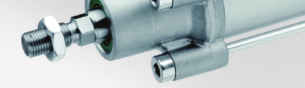
 Series TRB (tie rod) Optional guide unit Optional screw-in bearing Features (example PRA) What is AVENTICS Ideal Cushioning?")

2 Series PRA and TRB Pneumatic ISO Cylinders The next generation of ISO cylinders from AVENTICS The Series PRA and TRB cylinder series represent consistent further development of our proven ISO cylinder designs. They offer the classic solution for numerous tasks and applications in nearly all industries available worldwide to a uniform standard. The latest series are considerably lighter, more efficient and have superior cushioning design taking full advantage of the AVENTICS Ideal Cushioning technology. Series PRA (profile) Series TRB (tie rod) Optional guide unit Optional screw-in bearing Features (example PRA) What is AVENTICS Ideal Cushioning? Ideal cushioning is a combination of precise adjustable pneumatic cushions and elastic bumpers that work together to eliminate end-of-stroke bounce and minimize residual energy. This reduces vibration and noise while reducing cycle times. What s this mean for you? AVENTICS cylinders that are ideal cushioning capable, when properly adjusted, will last longer and run faster than other comparable cylinders. Our Velocity Time Meter measures piston speed to allow perfect adjustment of the cushions. Ideal cushioning allows machinery to last longer plus run faster and with less noise. Many times a AVENTICS Ideal Cushioning-capable cylinder of a smaller bore size can be used to do the same work as a larger cylinder. Elastic (PUR) and pneumatic ideal cushioning system Shorter cycle times due to higher air discharge volumes Ports in ISO-G (BSPP) or NPTF Die-cast aluminum cover minimizes material usage reducing weight Sensitive, high-resolution cushioning settings Piston rod seal with scraper, optional screwin bearing Rod threads in metric or inch Highly reinforced piston Hexagon wrench flats for easy installation Sintered bronze guide bushing Strong, corrosion resistant 431 stainless steel piston rod, strokes lengths in metric or inch Piston seals made of PUR, optional heat resistant Viton FPM Specifications for both PRA (PRofile Advanced) and TRB (Tie Rod Basic): Stroke range: or mm Working pressure: 22 to145psi (1.5 to 10 bar) Bore sizes: mm Temperature range: -4 F to +175 F (-20 C to +80 C) heat resistant version to +300 F (+150 C) Many styles and sizes of Series PRA/TRB are included in the AVENTICS Quick Ship focused delivery program. For details on the program and the part numbers included, visit
3 ISO 15552, Series PRA ISO 15552, Series TRB Profi le cylinder, ISO 15552, Series PRA & TRB Ø mm Common Specifi cations Profi le cylinder, ISO 15552, Series PRA Ø mm Ports: G 1/8 - G 1/2, 1/8 NPTF - 1/2 NPTF double-acting magnetic piston ideal cushioning single rod, male thread (Inch and Metric) Profi le cylinder, ISO 15552, Series PRA Ø mm Ports: G 1/8 - G 1/2, 1/8 NPTF - 1/2 NPTF double-acting magnetic piston ideal cushioning double rod, male thread (Inch and Metric) Profi le cylinder, ISO 15552, Series PRA Ø mm Ports: G 1/8 - G 1/2 double-acting heat resistant adjustable cushioning single rod, male thread (Metric Only) ISO 15552, Series TRB Ø mm Ports: G 1/8 - G 1/2, 1/8 NPTF - 1/2 NPTF double-acting magnetic piston ideal cushioning single rod, male thread (Inch and Metric) ISO 15552, Series TRB Ø mm Ports: G 1/8 - G 1/2, 1/8 NPTF - 1/2 NPTF double-acting magnetic piston ideal cushioning double rod, male thread (Inch and Metric) ISO 15552, Series TRB Ø mm Ports: G 1/8 - G 1/2 double-acting heat resistant adjustable cushioning single rod, male thread (Metric Only) ISO 15552, Series TRB (MT4) Ø mm Ports: G 1/8 - G 1/2, 1/8 NPTF - 1/2 NPTF double-acting magnetic piston mid-stroke fi xed trunnion mount ideal cushioning single rod, male thread (Metric Only) ISO 15552, Series TRB Ø mm Ports: G 1/8 - G 1/2 double-acting adjustable cushioning low friction cylinder (Metric Only) Screw-in bearing (PRA and TRB) and seal kits Screw-in bearing (PRA and TRB) seal kits 18 Cylinder mountings Bearing block AB7 with fi xed bearing (PRA and TRB) Cylinder mounting in accordance with ISO Clevis mounting AB6 (PRA and TRB) Cylinder mounting in accordance with ISO Bearing block with ball joint and foot, angled (PRA and TRB) Cylinder mounting in accordance with VDMA part 2 21 Clevis mounting MP2 (PRA and TRB) Cylinder mounting in accordance with ISO Rear eye MP4 for MP2 clevis mounting (PRA and TRB) Cylinder mounting in accordance with ISO Rear eye MP9 with rubber bushing (PRA and TRB) Cylinder mounting in accordance with ISO Bearing AT4 for trunnion mounting MT4 (PRA and TRB) Cylinder mounting in accordance with ISO Note: Cylinders marked adjustable cushioning do not have mechanical bumpers like the ones marked ideal cushioning.
 Cylinder mounting in accordance with ISO 15552 26 Trunnion mounting MT5/MT6, front or rear (PRA and TRB) Cylinder mounting in accordance with ISO 15552 27 Intermediate fl")
 30 Rod clevis AP2 (Metric) 31 Ball eye rod end AP6 (Metric) Inch rod accessories 31 32 Guide units Guide unit, GU1 (PRA and TRB) Ø 32-100 mm Plain bearing for standard cylinder ISO 15552")
4 4 MT4 center trunnion mounting (PRA only) Cylinder mounting in accordance with ISO Flange mounting MF1, MF2 (PRA and TRB) Cylinder mounting in accordance with ISO Rear eye with ball joint, MP6 (PRA and TRB) Cylinder mounting in accordance with ISO Trunnion mounting MT5/MT6, front or rear (PRA and TRB) Cylinder mounting in accordance with ISO Intermediate fl ange for multi-position cylinders (PRA and TRB) 28 Foot mounting MS1 (PRA and TRB) 28 AA4 pivot pin (PRA and TRB) 29 Piston rod mountings Piston rod nut MR9 (Metric) 30 Flexible spherical coupling PM5 (Metric) 30 Rod clevis AP2 (Metric) 31 Ball eye rod end AP6 (Metric) Inch rod accessories Guide units Guide unit, GU1 (PRA and TRB) Ø mm Plain bearing for standard cylinder ISO Guide unit, GH2 (PRA and TRB) Ø mm linear ball bearing for standard cylinder ISO Guide unit, GH1 (PRA and TRB) Ø mm Plain bearing for standard cylinder ISO Flange mounting (PRA and TRB) U version, for guide units, Ø mm 43 Flange mounting (PRA and TRB) for guide units, H version, Ø mm 44 Flexible coupling GU3 form C (PRA and TRB) for guide units version U and H, Ø
 Ø20-100 mm hold: spring force, release: compressed air 48 Locking Unit LU6 (PRA and TRB) Ø32-125 mm hold: non-adjustable spring force, releas: compressed air 49 Sensors and sensor")
 6 mm groove with cable Plug, M8, 3-pin Sensor, Series ST6 (PRA and TRB) 6 mm groove with cable Plug, M12, 3-pin, with knurled screw Sensor, Series SM6")
 8 mm groove with cable Plug, M8 Sensor, Series ST8 (PRA and TRB) 8 mm groove with cable Plug, M12, 3-pin, with knurled screw Connecting cable with plug (PRA and TRB)")
5 5 Flexible coupling GU3 form B (PRA and TRB) for guide units H version, Ø Holding unit, HU1 (PRA and TRB) Ø mm hold: spring force, release: compressed air 46 Holding cartridge, HU2 (PRA and TRB) Ø mm hold: spring force, release: compressed air 48 Locking Unit LU6 (PRA and TRB) Ø mm hold: non-adjustable spring force, releas: compressed air 49 Sensors and sensor mountings, accessories Sensor, Series ST6 (PRA and TRB) 6 mm groove with cable without wire end ferrule, tin-plated Sensor, Series ST6 (PRA and TRB) 6 mm groove with cable Plug, M8, 3-pin, with knurled screw Sensor, Series ST6 (PRA and TRB) 6 mm groove with cable Plug, M8, 3-pin Sensor, Series ST6 (PRA and TRB) 6 mm groove with cable Plug, M12, 3-pin, with knurled screw Sensor, Series SM6 (PRA and TRB) 6 mm groove with cable Plug, M8x1, 4-pin, with knurled screw distance measuring sensor Sensor, Series ST8 (PRA and TRB) 8 mm groove with cable without wire end ferrule, tin-plated Sensor, Series ST8 (PRA and TRB) 8 mm groove with cable Plug, M8 Sensor, Series ST8 (PRA and TRB) 8 mm groove with cable Plug, M12, 3-pin, with knurled screw Connecting cable with plug (PRA and TRB) without wire end ferrule tin-plated Connecting cable with plug, M8x1 (PRA and TRB) Socket, M8, 3-pin without wire end ferrule tin-plated, 3-pin 61 Connecting cable, Series CN1 (PRA and TRB) Socket, M12, 5-pin without wire end ferrule tin-plated, 5-pin 62 Sensors and sensor mountings, accessories (PRA only) Sensor mounting (PRA only) for Sensor Series ST6 to mount on cylinder, series PRA Sensor mounting (PRA only) for Sensor Series ST8 to mount on cylinder series PRA Groove lock profi le (PRA only) Sensors and sensor mountings, accessories (TRB only) Sensor mountings for Sensor Series ST6 to mount on cylinder series TRB Sensor mounting for Sensor Series ST6 to mount on cylinder series TRB 65 Sensor mounting for Sensor ST8 to mount on cylinder series TRB 66 Velocity - Timer - Meter, Series VTM for measuring piston speed and stroke times 66
6 6 Profile cylinder, ISO 15552, Series PRA & TRB Ø mm Common Specifications Standards ISO Compressed air connection internal thread, NPTF or ISO / ISO Working pressure min./max. 22 psi 145psi (1.5 to 10 bar) Ambient temperature min./max. -4ºF to + 175ºF(-20ºC to + 80ºC) High Temp version (1) 14ºF to +300ºF (-10ºC to +150ºC) Medium Compressed air Minimum filtration 50 μm Medium temperature min./max. -4ºF to + 175ºF(-20ºC to + 80ºC) Oil content of compressed air 0 mg/m³ - 5 mg/m³ Pressure for determining piston forces 6.3 bar (91.3 psi) Materials: Cylinder tube (2) Aluminum, anodized Piston rod 431 Stainless steel Front cover Die-cast aluminum End cover Die-cast aluminum Piston Seals (3) Polyurethane Piston rod nut Steel, galvanized Scraper (3) Polyurethane Profile cylinder, ISO 15552, Series PRA ISO 15552, Series TRB Piston Ø Bore 32mm / 1-1/4" 40mm / 1-1/2" 50mm / 2" 63mm / 2-1/2" Extending piston force (4) N (lb-f) 505 (372.7) 790 (583) 1235 (911.4) 1960 (1446.5) Retracting piston force (5) N (lb-f) 435 (321) 660 (487.1) 1035 (763.8) 1765 (1302.6) Max piston speed (extend) m/s (in/s) 3 (118.1) 3 (118.1) 2.5 (98.4) 2.5 (98.4) Cushion length mm (in) 11.5 (0.5) 15 (0.6) 17 (0.7) 16.5 (0.6) Max Cushioning energy J (ft-lb) 4.8 (3.54) 9 (6.64) 15 (11.06) 27 (19.91) Min. pressure PUR seals (typical break-away) [bar] (psi) 0.13 (1.89) 0.12 (1.74) 0.08 (1.16) 0.07 (1.02) Min. pressure FPM seals (typical break-away) [bar] (psi) 0.08 (1.16) 0.06 (0.87) 0.04 (0.58) 0.04 (0.58) Min. pressure low friction seals (6) (1) [bar] (psi) 0.05 (0.73) 0.04 (0.58) 0.03 (0.44) 0.03 (0.44) Stroke max. mm (in) 1600 (63) 1900 (74.8) 2100 (82.7) 2500 (98.4) Weight (PRA Single rod) (0mm stroke) kg (lb) 0.5 (1.1) 0.65 (1.43) 1.06 (2.34) 1.42 (3.13) Weight (PRA Single rod) +10 mm (1/2") stroke kg (lb) (0.06) (0.09) (0.13) (0.15) Weight (TRB Single rod) (0mm stroke) kg (lb) 0.46 (1.01) 0.67 (1.48) 1.14 (2.51) 1.4 (3.09) Weight (TRB Single rod) +10 mm (1/2") stroke kg (lb) (0.07) 0.03 (0.08) (0.1) (0.15) Weight (PRA Double rod) (0mm stroke) kg (lb) 0.58 (1.28) 0.8 (1.76) 1.34 (2.95) 1.72 (3.79) Weight (PRA Double rod) +10 mm (1/2") stroke kg (lb) (0.09) (0.13) (0.2) (0.22) Weight (TRB Double rod) (0mm stroke) kg (lb) 0.52 (1.15) 0.48 (1.06) 1.42 (3.13) 1.7 (3.75) Weight (TRB Double rod) +10 mm (1/2") stroke kg (lb) (0.09) (0.13) (0.17) (0.22) Note (7) (7) (8) (8) Notes (1) Not compatible with magnetic piston (2) TRB low friction version tube material is steel (3) Other materials available as options (4) Single rod only (5) Both extend and retract, double rod version (6) TRB Only (7) TRB Tie-rod material: Stainless steel (8) TRB Tie-rod material: Steel, galvanized Metric versions include rod nut, inch versions do not.
7 7 Profile cylinder, ISO 15552, Series PRA & TRB Ø mm Common Specifications Piston Ø Bore 80mm / 3" 100 / 4" 125mm / 5" Extending piston force (3) N (lb-f) 3165 (2335.8) 4945 (3649.4) 7725 (5701.1) Retracting piston force (4) N (lb-f) 2855 (2107) 4635 (3420.6) 7220 (5328.4) Max piston speed (extend) m/s (in/s) 1.8 (70.8) 1.8 (70.8) 1.2 (47.2) Cushion length mm (in) 19.5 (0.8) Max Cushioning energy J (ft-lb) 54 (39.83) 88 (64.9) 140 (103.25) Min. pressure PUR seals [bar] (psi) 0.05 (0.73) 0.03 (0.44) 0.03 (0.44) Min. pressure FPM seals [bar] (psi) 0.03 (0.44) 0.03 (0.44) 0.02 (0.29) Min. pressure low friction seals (5) (6) [bar] (psi) 0.02 (0.29) 0.02 (0.29) 0.01 (0.15) Stroke max. mm (in) 2800 (110.2) 2800 (110.2) 2750 (108.3) Weight (PRA Single rod) (0mm stroke) kg (lb) 2.37 (5.23) 3.51 (7.74) 6.72 (14.82) Weight (PRA Single rod) +10 mm (1/2") stroke kg (lb) (0.24) 0.1 (0.28) 0.15 (0.42) Weight (TRB Single rod) (0mm stroke) kg (lb) 2.12 (4.67) 3.16 (6.97) 6.92 (15.26) Weight (TRB Single rod) +10 mm (1/2") stroke kg (lb) 0.06 (0.17) (0.18) 0.21 (0.59) Weight (PRA Double rod) (0mm stroke) kg (lb) 2.92 (6.44) 4.08 (9) 8.92 (19.67) Weight (PRA Double rod) +10 mm (1/2") stroke kg (lb) (0.35) (0.39) 0.22 (0.62) Weight (TRB Double rod) (0mm stroke) kg (lb) 2.67 (5.89) 3.7 (8.16) 9 (19.85) Weight (TRB Double rod) +10 mm (1/2") stroke kg (lb) (0.28) (0.29) 0.26 (0.73) Note (8) (8) (8) Notes (1) Not compatible with magnetic piston (2) TRB low friction version tube material is steel (3) Other materials available as options (4) Single rod only (5) Both extend and retract, double rod version (6) TRB Only (7) TRB Tie-rod material: Stainless steel (8) TRB Tie-rod material: Steel, galvanized
8 8 Profile cylinder, ISO 15552, Series PRA Ø mm Ports: G 1/8 - G 1/2, 1/8 NPTF - 1/2 NPTF double-acting magnetic piston ideal cushioning single rod, male thread (Inch and Metric) Technical Remarks The pressure dew point must be at least 15 C under ambient and medium temperature and may not exceed 3 C. The oil content of air pressure must remain constant during the life cycle. ATEX-certified cylinders can be generated in the configurator. ATEX ID II 2G2D c T4 T135 C -20 C Ta 60 C For ATEX-certified cylinders, the temperature range specified in the header does not apply. See the ATEX ID. Inch Version Piston Ø (mm) Rod thread Ports Rod Ø (mm) 32 7/16-20 UNF 1/8 NPTF /2-20 UNF 1/4 NPTF /4-16 UNF 1/4 NPTF /4-16 UNF 3/8 NPTF /4-16 UNF 3/8 NPTF /4-16 UNF 1/2 NPTF UNF 1/2 NPTF 32 * Stroke 0010 R R R R R R R R R R R R R R R R R R R R R R R R R R R R R R R R R R R R R R R R R R R R R R R R R R R R R R R R R R R R R R R R R R R R R R R R R R R R R Metric Version Piston Ø (mm) Rod thread Ports Rod Ø (mm) 32 M10x1,25 G 1/ M12x1,25 G 1/ M16x1,5 G 1/ M16x1,5 G 3/ M20x1,5 G 3/ M20x1,5 G 1/ M27x2 G 1/2 32 ** Stroke R R R R R R R R R R R * First 3 digits of inch stroke are whole inches, 4th digit 1/8 increments ** Metric stroke in mm
9 9 Profile cylinder, ISO 15552, Series PRA Ø mm Ports: G 1/8 - G 1/2, 1/8 NPTF - 1/2 NPTF double-acting magnetic piston ideal cushioning single rod, male thread ATEX optional Dimensions L3 BG BG E L3 TG KK ØB ØMM ØBA E TG H RT RT KV EE EE PL PL SW KW VD VA A L2 WH L8+S S = stroke Piston Ø A -2 ØB d11 ØBA d11 BG min. E EE inch EE H KK inch KK KV /8 NPT G1/ /16-20 UNF M10x1, /4 NPT G1/4 53 1/2-20 UNF M12x1, /4 NPT G1/4 65 3/4-16 UNF M16x1, /8 NPT G 3/8 75 3/4-16 UNF M16x1, /8 NPT G 3/8 95 3/4-16 UNF M20x1, /2 NPT G 1/ /4-16 UNF M20x1, /2 NPT G 1/ UNF M27x2 41 Piston Ø KW ØMM f8 PL L2 L3 ±0,5 L8 RT SW TG VA -1 VD WH ±0,4 M ,5±0, ±1, ±0,7 M ±0, ±1, ±0,7 M ,5±0, ±1, ±0,8 M ,5±0, ±1, ±0,8 M ±0, ±1, ±1 M ±0, ±1, ±1 M ±1, ±2,2
10 10 Profile cylinder, ISO 15552, Series PRA Ø mm Ports: G 1/8 - G 1/2, 1/8 NPTF - 1/2 NPTF double-acting magnetic piston ideal cushioning double rod, male thread (Inch and Metric) Inch Version Metric Version Piston Ø (mm) Rod thread Ports Rod Ø (mm) Piston Ø (mm) Rod thread Ports Rod Ø (mm) 32 7/16-20 UNF 1/8 NPTF M10x1,25 G 1/ /2-20 UNF 1/4 NPTF M12x1,25 G 1/ /4-16 UNF 1/4 NPTF M16x1,5 G 1/ /4-16 UNF 3/8 NPTF M16x1,5 G 3/ /4-16 UNF 3/8 NPTF M20x1,5 G 3/ /4-16 UNF 1/2 NPTF M20x1,5 G 1/ UNF 1/2 NPTF 32 * Stroke 0010 R R R R R R R R R R R R R R R R R R R R R R R R R R R R R R R R R R R R R R R R R R R R R R R R R R R R R R R R R R R R R R R R R R R R R R R R R R R R R M27x2 G 1/2 32 ** Stroke 25 R R R R R R R R R R R R R R R R R R R R R R R R R R R R R R R R R R R R R R R R R R R R R R R R R R R R R R R R R R R R R R R R R R R R R R R R R R R R R * First 3 digits of inch stroke are whole inches, 4th digit 1/8 increments ** Metric stroke in mm Configurable product This product is configurable. Please use our configurator at or contact the nearest Bosch Rexroth sales office.
11 Profile cylinder, ISO 15552, Series PRA Ø mm Ports: G 1/8 - G 1/2 double-acting magnetic piston ideal cushioning double rod, male thread 11 Dimensions BG BG E L3 L3 TG KK ØB ØMM ØB E TG H RT RT KV EE EE PL PL SW KW VD VD A L2 WH L8+S ZM+2xS S = stroke Piston Ø A -2 ØB d11 BG min. E EE inch EE H KK inch KK KV KW ØMM f /8 NPT G 1/ /16-20 UNF M10x1, /4 NPT G 1/4 53 1/2-20 UNF M12x1, /4 NPT G 1/4 65 3/4-16 UNF M16x1, /8 NPT G 3/8 75 3/4-16 UNF M16x1, /8 NPT G 3/8 95 3/4-16 UNF M20x1, /2 NPT G 1/ /4-16 UNF M20x1, /2 NPT G 1/ UNF M27x Piston Ø PL L2 L3 ±0,5 L8 RT SW TG VD WH ZM ±0,4 M ,5±0,5 5 26±1, /-1, ±0,7 M ±0,5 5 30±1, /-1, ±0,7 M ,5±0,6 5 37±1, /-1, ±0,8 M ,5±0,7 5 37±1, /-1, ±0,8 M ±0,7 5 46±1, /-1, ±1 M ±0,7 5 51±1, ,5/ ±1 M ±1,1 7 65±2, ,5/-2
12 12 Profile cylinder, ISO 15552, Series PRA Ø mm Ports: G 1/8 - G 1/2 double-acting high temperature - up to 300 F (150 C) adjustable cushioning single rod, male thread (Metric Only) a5 Technical Remarks The pressure dew point must be at least 15 C under ambient and medium temperature and may not exceed 3 C. The oil content of air pressure must remain constant during the life cycle. Use only the approved oils from Bosch Rexroth, see chapter Technical information. Metric Version Piston Ø (mm) Rod thread Ports Rod Ø (mm) 32 M10x1,25 G 1/ M12x1,25 G 1/ M16x1,5 G 1/ M16x1,5 G 3/ M20x1,5 G 3/ M20x1,5 G 1/ M27x2 G 1/2 32 ** Stroke 25 R R R R R R R R R R R R R R R R R R R R R R R R R R R R R R R R R R R R R R R R R R R R R R R R R R R R R R R R R R R R R R R R R R R R R R R R R R R R R ** Metric stroke in mm Note - See page 8 for dimensions. Configurable product This product is configurable. Please use our configurator at or contact the nearest Bosch Rexroth sales office.
13 13 ISO 15552, Series TRB Ø mm Ports: G 1/8 - G 1/2, 1/8 NPTF - 1/2 NPTF double-acting magnetic piston ideal cushioning single rod, male thread ATEX optional (Inch and Metric) Inch Version Piston Ø (mm) Rod thread Ports Rod Ø (mm) 32 7/16-20 UNF 1/8 NPTF /2-20 UNF 1/4 NPTF /4-16 UNF 1/4 NPTF /4-16 UNF 3/8 NPTF /4-16 UNF 3/8 NPTF /4-16 UNF 1/2 NPTF UNF 1/2 NPTF 32 * Stroke 0010 R R R R R R R R R R R R R R R R R R R R R R R R R R R R R R R R R R R R R R R R R R R R R R R R R R R R R R R R R R R R R R R R R R R R R R R R R R R R R Metric Version Piston Ø (mm) Rod thread Ports Rod Ø (mm) 32 M10x1,25 G 1/ M12x1,25 G 1/ M16x1,5 G 1/ M16x1,5 G 3/ M20x1,5 G 3/ M20x1,5 G 1/ M27x2 G 1/2 32 ** Stroke * First 3 digits of inch stroke are whole inches, 4th digit 1/8 increments ** Metric stroke in mm
14 14 ISO 15552, Series TRB Ø mm Ports: G 1/8 - G 1/2, 1/8 NPTF - 1/2 NPTF double-acting magnetic piston ideal cushioning single rod, male thread ATEX optional Dimensions BG BG E RT L3 ØHT L3 RT TG ØB ØMM ØBA EE PL SW KW VA KK E TG H KV EE PL VD A L2 WH L8+S S = stroke Ø A -2 ØB d11 ØBA d11 BG min. E EE inch EE H ØHT KK inch KK KV /8 NPT G1/ /16-20 UNF M10x1, /4 NPT G1/ /2-20 UNF M12x1, /4 NPT G1/ /4-16 UNF M16x1, /8 NPT G3/ /4-16 UNF M16x1, /8 NPT G3/ /4-16 UNF M20x1, /2 NPT G1/ /4-16 UNF M20x1, /2 NPT G1/ UNF M27x2 41 Ø KW ØMM f8 PL L2 L3 ±0,5 L8 RT SW TG VA -1 VD WH ±0,4 M ,5±0, ±1, ±0,7 M ±0, ±1, ±0,7 M ,5±0, ±1, ±0,8 M ,5±0, ±1, ±0,8 M ±0, ±1, ±1 M ±0, ±1, ±1 M ±1, ±2,2
15 15 ISO 15552, Series TRB Ø mm Ports: G 1/8 - G 1/2, 1/8 NPTF - 1/2 NPTF double-acting magnetic piston ideal cushioning double rod, male thread (Inch and Metric) a17 Inch Version Piston Ø (mm) Rod thread Ports Rod Ø (mm) 32 7/16-20 UNF 1/8 NPTF /2-20 UNF 1/4 NPTF /4-16 UNF 1/4 NPTF /4-16 UNF 3/8 NPTF /4-16 UNF 3/8 NPTF /4-16 UNF 1/2 NPTF UNF 1/2 NPTF 32 * Stroke 0010 R R R R R R R R R R R R R R R R R R R R R R R R R R R R R R R R R R R R R R R R R R R R R R R R R R R R R R R R R R R R R R R R R R R R R R R R R R R R R Metric Version Piston Ø (mm) Rod thread Ports Rod Ø (mm) 32 M10x1,25 G 1/ M12x1,25 G 1/ M16x1,5 G 1/ M16x1,5 G 3/ M20x1,5 G 3/ M20x1,5 G 1/ M27x2 G 1/2 32 ** Stroke R * First 3 digits of inch stroke are whole inches, 4th digit 1/8 increments ** Metric stroke in mm
16 16 ISO 15552, Series TRB Ø mm Ports: G 1/8 - G 1/2, 1/8 NPTF - 1/2 NPTF double-acting magnetic piston ideal cushioning double rod, male thread Dimensions BG BG E RT L3 ØHT L3 TG ØB ØMM ØB E TG H RT KV PL EE EE PL KW SW VD VD KK A L2 WH L8+S ZM+2xS S = stroke Ø A -2 ØB d11 BG min. E EE inch EE H ØHT KK inch KK KV KW /8 NPT G1/ /16-20 UNF M10x1, /4 NPT G1/ /2-20 UNF M12x1, /4 NPT G1/ /4-16 UNF M16x1, /8 NPT G3/ /4-16 UNF M16x1, /8 NPT G3/ /4-16 UNF M20x1, /2 NPT G1/ /4-16 UNF M20x1, /2 NPT G1/ UNF M27x Ø ØMM f8 PL L2 L3 ±0,5 L8 RT SW TG VD WH ZM ±0,4 M ,5±0,5 5 26±1, /-1, ±0,7 M ±0,5 5 30±1, /-1, ±0,7 M ,5±0,6 5 37±1, /-1, ±0,8 M ,5±0,7 5 37±1, /-1, ±0,8 M ±0,7 5 46±1, /-1, ±1 M ±0,7 5 51±1, ,5/ ±1 M ±1,1 7 65±2,2
17 17 ISO 15552, Series TRB Ø mm Ports: G 1/8 - G 1/2 double-acting high temperature to 300 F (150 C) adjustable cushioning single rod: male thread (Metric Only) a5 Metric Version Piston Ø (mm) Rod thread Ports Rod Ø (mm) 32 M10x1,25 G 1/ M12x1,25 G 1/ M16x1,5 G 1/ M16x1,5 G 3/ M20x1,5 G 3/ M20x1,5 G 1/ M27x2 G 1/2 32 ** Stroke ** Metric stroke in mm Note - See page 13 for dimensions.
18 18 ISO 15552, Series TRB Ø mm Ports: G 1/8 - G 1/2, 1/8 NPTF - 1/2 NPTF double-acting magnetic piston ideal cushioning mid-stroke fixed trunnion mount single rod, male thread (Metric Only) Metric Version Piston Ø (mm) Rod thread Ports Rod Ø (mm) 32 M10x1,25 G 1/ M12x1,25 G 1/ M16x1,5 G 1/ M16x1,5 G 3/ M20x1,5 G 3/ M20x1,5 G 1/ M27x2 G 1/2 32 ** Stroke R R ** Metric stroke in mm Note: Trunnion is delivered in mid-stroke position, field adjustable. Dimensions BG BG E RT L3 TM TG XV+S/2 EE EE SW VD PL ØTD TM PL VA KW KK ØB ØMM ØBA HW ØHT L3 RT E TG H KV A L2 TL WH XVmin XVmax+S TK L8 + S S = stroke Configurable product This product is configurable. Please use our configurator at or contact the nearest Bosch Rexroth sales office.
19 19 ISO 15552, Series TRB Ø mm Ports: G 1/8 - G 1/2 double-acting magnetic piston ideal cushioning mid-stroke fixed trunnion mount single rod, male thread Ø A -2 ØB d11 ØBA d11 BG min. E EE H ØHT HW KK G1/ M10x1, G1/ M12x1, G1/ M16x1, G3/ M16x1, G3/ M20x1, G1/ M20x1, G1/ M27x2 Ø KV KW ØMM f8 PL L2 L3 ±0,5 L8 RT SW TG ±0,4 M ,5±0, ±0,7 M ±0, ±0,7 M ,5±0, ±0,8 M ,5±0, ±0,8 M ±0, ±1 M ±0, ±1 M ±1,1 Ø VA -1 VD WH HW ØTD e9 TK TL h14 TM h14 XVmin Xvmax XV ±1, ±1, ±1, ±1, ±1, ±1, ±2, ISO 15552, Series TRB Ø mm Ports: G 1/8 - G 1/2 double-acting adjustable cushioning low friction cylinder (Metric Only) Metric Version Piston Ø (mm) Rod thread Ports Rod Ø (mm) 32 M10x1,25 G 1/ M12x1,25 G 1/ M16x1,5 G 1/ M16x1,5 G 3/ M20x1,5 G 3/ M20x1,5 G 1/ M27x2 G 1/2 32 ** Stroke 25 R R R R R R R R R R R R R R R R R R R R R R R R R R R R R R R R R R R R R R R R R R R R R R R R R R R R R R R R R R R R R R R R R R R R R R ** Metric stroke in mm Note - See page 13 for dimensions.
 diameter / Repair Seal Kits Screw-in bearing Replacement screw-in rod bearings - Standard (PRA and TRB) Material Piston rod bushing Wiper Steel, bearing layer composite PVDF + PTFE Metal or")
20 20 Standard Cylinder Series PRA and TRB Optional screw-in bearings, mm ( ) diameter / Repair Seal Kits Screw-in bearing Replacement screw-in rod bearings - Standard (PRA and TRB) Material Piston rod bushing Wiper Steel, bearing layer composite PVDF + PTFE Metal or Polyesterelastomer (PEE) or Carbon-filled PTFE Seals (standard) Nitrile rubber (high temp) or Viton Casing Anodized aluminum Ambient temperature range High temp versions 5 F to 158 F (-15 C to +70 C) Up to 300 F (150 C) In very difficult environments high demands are made on a wiper. Depending on the environment different types of wipers are suitable. To provide maximum flexibility and maintenance frendliness we offer for these applications different adapters. Note that the cylinder is still to ISO standards dimensions. PRA/TRB Screw-in Bearings Replacement Parts Bore size 32 (1 1/4 ) 40 (1 1/2 ) 50 (2 ) 63 (2 1/2 ) 80 (3 ) 100 (4 ) 125 (5 ) mm (inch) Metal n/a PEE PTFE Metal (high temp) n/a PTFE (high temp) Repair kits for new and old style TRB and PRA Cylinders. Includes cushion seal, piston seal, rod seal and scraper, bearing, bumper and grease. Bore size mm (inch) Standard Part Number Low Friction Part Number High Temp Part Number Metal Scraper Part Number* R R R R R R R R R R R R R R R R There are differences in the materials of the non-wearing parts of the cylinder versions that preclude converting cylinder versions by just changing seals. The seals are dimensionally interchangeable between versions. *Metal scaper part numbers include complete head.

21 21 Bearing block AB7 with fixed bearing Cylinder mounting in accordance with ISO Part No. Piston Ø BR BT Ø CK H9 Ø EB H ,2/ 0, ,2/-0, ,2/ 0, ,2/ 0, ,2/ 0, ,2/ 0, , ,5/ 1, Part No. T TE JS14 UL 1) UR 1) Material Surface , Nodular galvanized graphite iron Nodular galvanized graphite iron , Nodular galvanized graphite iron , Nodular galvanized graphite iron , Nodular galvanized graphite iron , Nodular galvanized graphite iron , Nodular galvanized graphite iron 1) max. EM GL JS14 Ø HB H13 L3 1) PH JS15 RA JS14
 L4 ±0,5 F7 1827001593 32 3.3 10 14 34 6.6 11 30 49 22 4.5 5.5 1827001594 40 4.3 12 16 40 6.")
22 22 Clevis mounting AB6 Cylinder mounting in accordance with ISO CP CG Ød3 L 4 E TG ØD B3 Ød4 CF SR R T L11 L1 FM Scope of delivery: clevis mounting incl. pivot pins and mounting screws Part No. Piston Ø B3 ±0,2 Ø CF CG D10 CP d12 Ø d3 Ø d4 Ø D E FM ±0,2 L1 1) L4 ±0,5 F Part No. L11 0,5 R4 SR T ±0,2 TG Material ,5 ±0,2 Aluminum, forged ±0,2 Aluminum, forged ,5 ±0,2 Aluminum, forged ,5 ±0,2 Aluminum, forged ±0,2 Aluminum, forged ±0,2 Aluminum, forged ±0,3 Aluminum, forged 1) Min.
 BT CK H7 EA 1) Ø EB 2) EM 0,1 1827001784 32 16 9 10 10.5 11 14 21 16 6.6 1.6 32 1827001785 40 18 9 12 12 11 16 24 16 6.6 1.6 36 1827001786 50 21 11 16 15 15 21 33 23 9 1.")

23 23 Bearing block with ball joint and foot, angled Cylinder mounting in accordance with VDMA part Part No. Piston Ø BR 1) BT CK H7 EA 1) Ø EB 2) EM 0, Part No. RA JS14 TE JS14 UL 1) UR 1) Material Surface Nodular graphite iron Nodular graphite iron Nodular graphite iron Nodular graphite iron Nodular graphite iron Nodular graphite iron Nodular graphite iron 1) max. 2) Min. galvanized galvanized galvanized galvanized galvanized galvanized galvanized GL JS14 H1 1) Ø HB H13 L2 1) PH JS15 Clevis mounting MP2 Cylinder mounting in accordance with ISO (for pivot pin, see AA4, page 29) P523_025 Scope of delivery: clevis mounting incl. mounting screws
24 24 Part No. Piston Ø CB H14 Ø CD H9 E FL L 1) MR 2) UB h13 TG Material ±1 22 ±0, ,5 ±0,2 Aluminum, forged ±1 25 ±0, ±0,2 Aluminum, forged ±1 27 ±0, ,5 ±0,2 Aluminum, forged ±1 32 ±0, ,5 ±0,2 Aluminum, forged ±1 36 ±0, ,0 ±0,2 Aluminum, forged ±1 41 ±0, ,0 ±0,2 Aluminum, forged ±0, ±0,3 Nodular graphite iron Part No. Surface galvanized 1) Min. 2) max. Rear eye MP4 for MP2 clevis mounting Cylinder mounting in accordance with ISO P523_024 Scope of delivery: clevis incl. mounting screws _a Part No. Piston Ø CD H9 Ø D Ø D1 E EW FL ±0,2 I ±0,5 L 1) L1 1) MR 2) H ,2/ 0, H ,2/ 0, H ,2/ 0, H ,2/ 0, H ,2/ 0, H ,2/ 0, H ,5/ 1,
25 25 Part No. TG Material Surface ,5 ±0,2 Aluminum, - forged ±0,2 Aluminum, - forged ,5 ±0,2 Aluminum, - forged ,5 ±0,2 Aluminum, - forged ±0,2 Aluminum, - forged ±0,2 Aluminum, - forged ±0,3 Nodular galvanized graphite iron 1) Min. 2) max. Rear eye MP9 with rubber bushing Cylinder mounting in accordance with ISO E ØCD E TG P523_026 EW L FL MR Scope of delivery: clevis incl. mounting screws Part No. Piston Ø CD H9 E EW FL L MR TG ±0,2 Material Weight [kg] Die-cast 0.1 aluminum Die-cast 0.1 aluminum Die-cast 0.1 aluminum Die-cast 0.2 aluminum Die-cast 0.3 aluminum Die-cast 0.4 aluminum Die-cast aluminum 0.7

26 26 Bearing AT4 for trunnion mounting MT4 Cylinder mounting in accordance with ISO ØF ØHB N FN ØCR TH UL NH NH1 FK Part No. Piston Ø Ø CR H7 Ø F H13 FK ±0,1 FN Ø HB H12 N 0,4 NH NH1 TH ±0,15 UL f ±0, ±0, , ±0, ±0, , ±0, ±0, , ±0, ±0,2 75 Part No. Material Surface Steel galvanized Steel galvanized Steel galvanized Steel galvanized MT4 center trunnion mounting (PRA only) Cylinder mounting in accordance with ISO
27 27 Part No. Piston Ø Ø TD e9 TK 2) TL h14 TM UW Material Surface Nodular galvanized graphite iron Nodular galvanized graphite iron Nodular galvanized graphite iron Nodular galvanized graphite iron Nodular galvanized graphite iron Nodular galvanized graphite iron Nodular galvanized graphite iron 2) max. Flange mounting MF1, MF2 Cylinder mounting in accordance with ISO Scope of delivery: flange mounting incl. mounting screws Part No. Piston Ø Ø d H11 Ø d1 Ø d2 E 1) Ø FB L4 MF R TF TG ,5 ±0, ±0, ,5 ±0, ,5 ±0, ±0, ±0, ±0,3 Part No. UF Material Surface Steel galvanized Steel galvanized Steel galvanized Steel galvanized Steel galvanized Steel galvanized Steel galvanized 1) max.

28 28 Rear eye with ball joint, MP6 Cylinder mounting in accordance with ISO ER CN E TG 4 E TG I 3 EN EU FL H I 2 R Ød _d Scope of delivery: clevis incl. mounting screws Part No. Piston Ø Ø CN H7 Ø d1 H13 E EN 0,1 ER EU FL ±0,2 H l2 l3 min Part No. TG Material ,5 ±0,2 Aluminum, forged ±0,2 Aluminum, forged ,5 ±0,2 Aluminum, forged ,5 ±0,2 Aluminum, forged ±0,2 Aluminum, forged ±0,2 Aluminum, forged ±0,3 Aluminum, forged R min.


29 29 Trunnion mounting MT5/MT6, front or rear Cylinder mounting in accordance with ISO The delivered product may vary from that in the illustration. Scope of delivery: trunnion mounting incl. mounting screws Part No. Piston Ø Ø Ø d Ø d1 Ø d2 L1 TD TG ±0,2 TK TL h14 TM h14 UW H Part No. Material Surface Nodular galvanized graphite iron Nodular galvanized graphite iron Nodular galvanized graphite iron Nodular galvanized graphite iron Nodular galvanized graphite iron Nodular galvanized graphite iron Nodular galvanized graphite iron
30 30 Intermediate flange for multi-position cylinders Ød1 TG E P523_049 D TG E D271_052 Scope of delivery: flange and mounting screws Part No. Piston Ø D Ø d1 N7 E TG Material Aluminum Aluminum Aluminum Aluminum Aluminum Aluminum Aluminum Foot mounting MS Scope of delivery: 2 foot mountings incl. mounting screws Part No. Piston Ø Ø AB AO AT AU ±0,2 Ø d E L1 L2 R TG ±0, ±0, ±0, ±0, ±0, ±0, ±0, ±0, ±0,3 110 ±0,3 Part No. TR Material Surface Steel galvanized Steel galvanized Steel galvanized
 00105158 00105182 Part No.")
31 31 Part No. TR Material Surface Steel galvanized Steel galvanized Steel galvanized Steel galvanized AA4 pivot pin (for MP2) Part No. Piston Ø Ø EK e8 EL Ø d 1) L6 1) Material Surface ISO Note , Steel galvanized - 2) , Steel galvanized - 2) , Steel galvanized - 2) , Steel galvanized - 2) , Steel galvanized - 2) , Steel galvanized - 2) , ,5 Steel galvanized ISO ) 1) max. 2) Scope of delivery: pivot pins incl. circlips
![32 Additional Piston rod nut MR9 (Metric) KK 00105168 KV KW 00105192 Part No. KK KV KW Material Surface Weight [kg] 1823300020 M10x1,25 17 6 Steel galvanized 0.](/docs-images/78/77126869/images/32-1.jpg "01 1823300021 M12x1,25 19 7 Steel galvanized 0.012 1823300030 M16x1,5 24 8 Steel galvanized 0.017 1823300031 M20x1,5 30 10 Steel galvanized 0.03 1823300029 M27x2 41 13.5 Steel galvanized 0.")
 00105169 * angle equalization ** Radial joint from 0,5-2 mm D300_029 Part No. KK B1 Ø D1 D2 Ø D3 F L ±2 L2 L3 ±1 SW1 SW2 SW3 1826409002 M10x1,25 6 21.")
32 32 Additional Piston rod nut MR9 (Metric) KK KV KW Part No. KK KV KW Material Surface Weight [kg] M10x1, Steel galvanized M12x1, Steel galvanized M16x1, Steel galvanized M20x1, Steel galvanized M27x Steel galvanized M36x Steel galvanized M42x Steel galvanized 0.37 Flexible spherical coupling PM5 (Metric) * angle equalization ** Radial joint from 0,5-2 mm D300_029 Part No. KK B1 Ø D1 D2 Ø D3 F L ±2 L2 L3 ±1 SW1 SW2 SW M10x1, M12x1, M16x1, M20x1, M27x Part No. SW4 Material Surface Weight [kg] Steel galvanized Steel galvanized Steel galvanized Steel galvanized Steel galvanized 1.7

33 33 Rod clevis AP2 (Metric) Fig.1 Fig. 2 CK CK BL CM BL CM LE KK LE KK ER CE ER CE CL ØD1 CL ØD Part No. KK Fig. BL CE Ø CK H9 CL CM Ø D1 ER LE M10x1, M12x1, M16x1, M20x1, M27x Part No. Material Surface Weight [kg] Steel galvanized Steel galvanized Steel galvanized Steel galvanized Steel galvanized 2 Ball eye rod end AP6 (Metric) CE ER EN EU KK AA ØCN SW z z LF AV Part No. KK AA AV min. CE Ø CN H7 EN 0,1 ER EU max. LF SW Z [ ] max. Material Surface Weight [kg] M10x1, Steel galvanized M12x1, Steel galvanized M16x1, Steel galvanized M20x1, Steel galvanized M27x Steel galvanized 1.17
34 34 Inch rod accessories Select by KK to match rod thread Bore KK CD Rod eye Rod clevis 32 7/16-20 UNF R R /2-20 UNF R R /4-16 UNF R R /4-16 UNF R R /4-16 UNF R R /4-16 UNF R R UNF R R Select by CD to match pivot pin Bore KK CD Pivot pin Clevis Bracket Eye Bracket 32 7/16-20 UNF R R R /2-20 UNF R R R /4-16 UNF R R R /4-16 UNF R R R /4-16 UNF R R R /4-16 UNF R R R UNF R R R Dimensions Rod Eye A CA CB CD ER KK R R /2-20 R /4-16 R Clevis Bracket AA CB CD CW CW DD R /8-24 R /2-20 R /2-20 Clevis Bracket E F FL LR M MR R R R Dimensions Rod Clevis A CB CD CE CH CW ER KK R /16-20 R /2-20 R /4-16 R Eye Bracket AA CB CD DB E F FL LR M MR R R R Pivot Pin CD CL CP w/snap ring R R R Note: The inch clevis bracket and eye bracket are for use with the inch rod eye and rod clevis, not for mounting directly to the cylinder. Metric versions include rod nut, inch versions do not.

35 35 Guide unit, GU1 Ø mm Plain bearing for cylinder with metric rod threads Ambient temperature min./max. -20 C / 80 C Materials: Bearing housings Bearing type Carrying plate Flexible coupling in carrying plate Guide rods Aluminum, black anodized Sintered bronze Aluminum, black anodized Stainless steel Stainless steel, smooth rolled Suitable [mm] piston Ø Weight 0 mm stroke [kg] mm stroke [kg] Suitable [mm] 100 piston Ø Weight 0 mm stroke [kg] mm stroke [kg] Suitable piston Ø mm (inch) Stroke 50 (2 ) (4 ) (6 ) (8 ) (10 ) (13 ) (16 ) (20 ) (24 ) (32 ) (39 ) (47 ) Note - Inch dimensions rounded to the nearest whole number. - See internet configurator for cylinders with NPT ports and metric rod threads.
36 36 Ø mm L3 L1 L2 B L4 L5 L6 SW B-B L14 L15 B1 B2 B3 A B4 B5 T1 D1 B6 B7 T2 D4 D5 G2 B8 A B L7 L8 T2 L9+SC L10 L11+S G2 A-A D3 L16 D6 KK D2 Y X L12 L13 G1 L S = stroke SC = cylinder stroke X = max. play (axial) Y = min. play (radial) Ø B1 B2 B3 B4 B5 B6 B7 B8 D1 D2 D3 D4 D5 D M M M M M M8 30 Ø G1 G2 KK L1 L2 L3 L4 L5 L6 L7 L8 L9 L10 32 M6 M6 M10x1, M6 M6 M12x1, M8 M8 M16x1, M8 M8 M16x1, M10 M10 M20x1, M10 M10 M20x1, Ø L11 L12 L13 L14 L15 L16 L17 SW T1 T
37 37 Ø L11 L12 L13 L14 L15 L16 L17 SW T1 T Useful load _a F= useful load, Z = projection Guide unit, GH2 Ø mm linear ball bearing for cylinder with metric rod threads Ambient temperature min./max. -20 C / 80 C Materials: Bearing type Carrying plate Flexible coupling in carrying plate Guide rods Steel Aluminum, black anodized Stainless steel Stainless steel, ground Suitable [mm] piston Ø Weight 0 mm stroke [kg] mm stroke [kg] Suitable [mm] 100 piston Ø Weight 0 mm stroke [kg] mm stroke [kg] 0.039
38 38 Suitable piston Ø [mm] Min. play (radial) [mm] (inch) Stroke 50 (2 ) (4 ) (8 ) (13 ) (20 ) (24 ) (32 ) (39 ) (47 ) Note - Inch dimensions rounded to the nearest whole number. - See internet configurator for cylinders with NPT ports and metric rod threads.
39 39 Ø mm B-B L1 L3 L14 L2 SW 1 L4 L5 B L15 B1 B2 B3 B4 B5 B6 B7 T3 G2 T3 A A B8 B9 B10 B11 D5 D6 D7 B12 L9+S L6 B L7 L10 L8 T2 L16 T2 L11+SC G2 D6 T1 A-A D3 D4 L17 D1 D2 D8 KK Y X SW 2 L12 L13 G1 L S = stroke SC = cylinder stroke X = max. play (axial) Y = min. play (radial) Hexagon in guide rod Ø B1 B2 B3 B4 B5 B6 B7 B8 B9 B10 B ±0, ±0, ±0, ±0, ±0, ±0, ±0, ±0, ±0, ±0, ±0, ±0, ±0, ±0, ±0, ±0, ±0, ±0, Ø B12 D1 D2 D3 D4 D5 D6 D7 D8 G1 G2 KK L H H7 30 M M6 M6 M10x1, H H7 35 M8 18 M6 M6 M12x1, H H7 40 M8 24 M8 M8 M16x1, H H7 45 M8 24 M8 M8 M16x1, H H7 45 M8 30 M10 M10 M20x1, H H7 55 M8 30 M10 M10 M20x1,5 120 Ø L2 L3 L4 L5 L6 L7 L8 L9 L10 L11 L12 L13 L14 L
40 40 Ø L2 L3 L4 L5 L6 L7 L8 L9 L10 L11 L12 L13 L14 L Ø L16 L17 L18 T1 T2 T3 SW1 SW ,5 ±0, ±0, ,5 ±0, ,5 ±0, ±0, ±0, Useful load F[N] _a / / X [mm] Service life 2x10 m _a F[N] / / X[mm] Service life 5x10 m F= useful load, Z = projection _a
41 41 Reduction of useful load on short strokes _a k=correction factor: normal=1; shock loaded=2 With a short stroke, the nominal load data determined from the diagram must be multiplied by the correction factor k. These short-stroke adjustments are already included in the load diagram for a displacement of up to 60 mm. Bending due to own load _a F = useful load (at the load center), SF = bending, Z = projection _a Bending due to 10 N load _a F = useful load (at the load center), SF = bending, Z = projection _a
42 42 Guide unit, GH1 Ø mm Plain bearing for cylinder with metric rod threads Ambient temperature min./max. -20 C / 80 C Materials: Bearing housings Bearing type Carrying plate Flexible coupling in carrying plate Guide rods Aluminum, black anodized Sintered bronze Aluminum, black anodized Stainless steel Stainless steel, smooth rolled Suitable [mm] piston Ø Weight 0 mm stroke [kg] mm stroke [kg] Suitable [mm] 100 piston Ø Weight 0 mm stroke [kg] mm stroke [kg] Suitable piston Ø [mm] Min. play (radial) [mm] (inch) Stroke 50 (2 ) (4 ) (6 ) (8 ) (10 ) (13 ) (16 ) (20 ) (24 ) (32 ) (39 ) (47 ) Note - Inch dimensions rounded to the nearest whole number. - See internet configurator for cylinders with NPT ports and metric rod threads.
43 43 Ø mm B-B L1 L3 L14 L2 SW 1 L4 L5 B L15 B1 B2 B3 B4 B5 B6 B7 T3 G2 T3 A A B8 B9 B10 B11 D5 D6 D7 B12 L9+S L6 B L7 L10 L8 T2 L16 T2 L11+SC G2 D6 T1 A-A D3 D4 L17 D1 D2 D8 KK Y X L12 L13 G1 L S = stroke SC = cylinder stroke X = max. play (axial) Y = min. play (radial) Ø B1 B2 B3 B4 B5 B6 B7 B8 B9 B10 B ±0, ±0, ±0, ±0, ±0, ±0, ±0, ±0, ±0, ±0, ±0, ±0, ±0, ±0, ±0, ±0, ±0, ±0, Ø B12 D1 D2 D3 D4 D5 D6 D7 D8 G1 G2 KK L H H7 30 M M6 M6 M10x1, H H7 35 M8 18 M6 M6 M12x1, H H7 40 M8 24 M8 M8 M16x1, H H7 45 M8 24 M8 M8 M16x1, H H7 45 M8 30 M10 M10 M20x1, H H7 55 M8 30 M10 M10 M20x1,5 120 Ø L2 L3 L4 L5 L6 L7 L8 L9 L10 L11 L12 L13 L14 L
44 44 Ø L2 L3 L4 L5 L6 L7 L8 L9 L10 L11 L12 L13 L14 L Ø L16 L17 L18 T1 T2 T3 SW ,5 ±0, ±0, ,5 ±0, ,5 ±0, ±0, ±0, Useful load F= useful load, Z = projection Bending due to own load F = useful load (at the load center), SF = bending, Z = projection

45 45 Bending due to 10 N load F = useful load (at the load center), SF = bending, Z = projection Flange mounting U version, for guide units, Ø mm UF TF TG FB L4 S MF R E Part No. Ø E FB L4 MF R S TF TG UF Material Steel, nickelplated Steel, nickelplated Part No. Surface galvanized galvanized A = Guide unit B = Rod coupling C = Mounting flange
46 46 Flange mounting for guide units, H version, Ø mm Part No. Ø E Ø FB L4 MF R TF TG UF Material Surface / Steel, galvanized galvanized / Steel, galvanized galvanized Steel, galvanized galvanized Steel, galvanized galvanized Steel, galvanized galvanized Steel, galvanized galvanized Steel, galvanized galvanized Steel, galvanized galvanized A = Guide unit B = Rod coupling C = Mounting flange Flexible coupling GU3 for guide units version U and H, Ø * Radial joint from 2-2,5 mm Scope of delivery: flexible coupling incl. mounting screws

47 47 Part No. Ø M G A B C D ØE ØF /16 2x M4x10 M x M6x12 M12x1, /63 4x M6x14 M16x1, Part No. Material Stainless steel Stainless steel Stainless steel Flexible coupling GU3 for guide units H version, Ø * Radial joint from 1,5-1,8 mm Scope of delivery: flexible coupling incl. mounting screws _a Part No. Ø M G A B C D ØE ØF x M5x12 M /32 2x M5x12 M10x1, /100 4x M6x20 M20x1, Part No. Material Stainless steel Stainless steel Stainless steel
48 48 Holding unit, HU1 Ø mm hold: spring force, release: compressed air Function Working pressure min./max. Controlpressure min./max. Ambient temperature min./max. Medium temperature min./max. Particle size max. Oil content of compressed air Hold with clamping jaws 4 bar / 8 bar -- / 8 bar -10 C / +60 C -10 C / +60 C 5 μm 0 mg/m³ - 5 mg/m³ Materials: Housing Aluminum, black anodized Technical Remarks The pressure dew point must be at least 15 C under ambient and medium temperature and may not exceed 3 C. The oil content of air pressure must remain constant during the life cycle. Use only the approved oils from Bosch Rexroth, see chapter Technical information. Warning: The holding unit may NOT be used for the following applications: - for dynamic holding - in or as safety equipment Holding unit may only be unlocked when turned off NOTE: The minimum control pressure is >= working pressure! Piston Ø suitable piston rod diameter h8 tolerance piston rod extension Compressed air connection Holding force Weight Part No M G 1/ G 1/ G 1/ G 1/ G 1/ [N] Caution: To use holding unit in combination with a linear guide, add the following rod extensions to the cylinder (in addition to configuring the cylinder to accept a rod holding unit): 32mm bore 6mm, 40mm bore 10mm, 50/63/80mm bores 13mm, and 100mm bore 23mm.
49 49 Dimensions A - A L3 1) D5 L6 2) D4 A D2 ØD1 D6 D3 L9 3) G L5 L4 A L2 L8 L1 L7 WH ZJ+S 1) air connection 2) Holding cartridge 3) 4 mounting screws S = stroke A Ø D1 Ø D2 Ø D3 Ø D4 D5 L1 L2 L3 L4 L5 L , M G 1/ , G 1/ , G 1/ G 1/ , G 1/ L7 L8 L9 G WH ZJ M M M M M M

50 50 Holding cartridge, HU2 Ø mm hold: spring force, release: compressed air 2) A C E 1) F L3 L2 L4 L1 D A ) piston rod 2) air connection Technical Remarks The pressure dew point must be at least 15 C under ambient and medium temperature and may not exceed 3 C. The oil content of air pressure must remain constant during the life cycle. Warning: The holding cartridge may NOT be used for the following applications: - for dynamic holding - in or as safety equipment Holding cartridge may only be unlocked when air pressure is turned off NOTE: The minimum control pressure is >= working pressure! Piston Ø suitable piston rod diameter h8 tolerance Compressed air connection Holding force Weight Part No M M G 1/ M G 1/ G 1/ G 1/ G 1/ [N] Ø D Ø A C Ø E Ø F L1 L2 L3 1) L M5 20 D M5 20 D M5 25 D G 1/8 28 D G 1/8 35 D G 1/8 38 D G 1/8 48 D G 1/8 58 D ) Min.

51 51 Locking Unit LU6 Ø mm Hold: non-adjustable spring force, Release: compressed air (for new applications) Version Function Release pressure Ambient temperature min./max. Medium temperature min./max. Medium Max. particle size Oil content of compressed air Materials: Housing Seal and Scraper Clamping jaw lock Hold with clamping jaws 4 bar / 10 bar -25 C / +80 C -25 C / +80 C Compressed air 5 μm 0 mg/m³ - 5 mg/m³ Aluminum, anodized Nitrile butadiene rubber Technical Remarks The pressure dew point must be at least 15 C under ambient and medium temperature and may not exceed 3 C. The oil content of air pressure must remain constant during the life cycle. Use only the approved oils from Bosch Rexroth Warning: The brake may NOT be used for the following applications: - for dynamic holding - in or as safety equipment NOTE: Before pressurizing the lock, make sure that there isa balance of forces at the piston on the drive cylinder. Please see the operating instructions for further information relevant for safety.

52 52 Sensor, Series ST6 6 mm groove with cable without wire end ferrule, tin-plated (for new applications) _2 Ambient temperature min./max. -25 C / +70 C Protection class according to EN IP :2000 Switching point precision [mm] ±0,1 Switching capacity 3 W / 3 VA LED status display Yellow Vibration resistance Hz, 1 mm Shock resistance 30 g / 11 ms Materials: Housing Cable Polyamide Polyurethane Type of contact cable length L DC operating voltage Min./max. Operational voltage AC Min./max. DC switching current, max. AC switching current, max. [m] [V] [V] [A] [A] Part No. Reed 3 10 / / 110 0, 13 0,13 R PNP NPN BN BK BU BN BK BU BN BK BU RL RL RL + / / ~ / + / ~ + + Reed electronic PNP electronic NPN Part No. Voltage drop U at Imax R R ) short circuit protected 2) short circuit resistant; short circuit protected interfaces: without wire end ferrule, tin-plated / / 30 0,13 0, R / , R / Protective resistor for reed Max. switching frequency Operating current, not switched Operating current, switched [V] [Ω] [khz] [ma] [ma] I*Rs 15 < 0,3 - < 10 1) 2,5 - < 1,0 < 20 < 30 2) 2,5 - < 1,0 < 20 < 30 2) Note
53 53 Dimensions 30,5 L 36 x 0,07 mm 2 4,2 1* 3* 2,8 3 x 0,14 mm 2 40 BN BU BK 6,2 X 2* 9,15 15,3 1* = sensor element 2* = clamping screw 3* = LED L = cable length BN = brown, BK = black, BU = blue X = electronic: 6 mm, Reed: 10 mm _b Sensor, Series ST6 6 mm groove with cable Plug, M8, 3-pin, with knurled screw (for new applications) _5 Ambient temperature min./max. -25 C / +70 C Protection class according to EN IP :2000 Switching point precision [mm] ±0,1 Switching capacity 3 W / 3 VA LED status display Yellow Vibration resistance Hz, 1 mm Shock resistance 30 g / 11 ms Materials: Housing Polyamide 1 BN + / / ~ 4 BK RL 3 BU / + / ~ 1 BN + 4 BK RL PNP 3 BU Type of contact Reed electronic PNP cable length L DC operating voltage Min./max. Operational voltage AC Min./max. DC switching current, max. AC switching current, max. Part No. [m] [V] [V] [A] [A] / / 30 0,13 0, / ,1 R NPN BN BK BU RL + electronic NPN /
54 54 Part No R Voltage drop U at Imax Protective resistor for reed Max. switching frequency Operating current, not switched Operating current, switched [V] [Ω] [khz] [ma] [ma] Material Cable I*Rs 15 < 0,3 - < 10 Polyurethane 1) 2,5 - < 1,0 < 20 < 30 Polyurethane Polyvinyl chloride Polyurethane ,5 - < 1,0 < 20 < 30 Polyurethane 2) 1) short circuit protected 2) short circuit resistant; short circuit protected interfaces: Plug; M8; 3-pin; with knurled screw Note 2) Dimensions 1* = sensor element 2* = clamping screw 3* = LED L = cable length X = electronic: 6 mm, Reed: 10 mm Pin assignment: 1 = (+), 3 = (-), 4 = (OUT), EN : _d Sensor, Series ST6 6 mm groove with cable Plug, M8, 3-pin (for new applications) _3 Ambient temperature min./max. -25 C / +70 C Protection class according to EN IP :2000 Switching point precision [mm] ±0,1 Switching capacity 3 W / 3 VA LED status display Yellow Vibration resistance Hz, 1 mm Shock resistance 30 g / 11 ms Materials: Housing Cable Polyamide Polyurethane
55 55 Type of contact cable length L DC operating voltage Min./max. Operational voltage AC Min./max. DC switching current, max. AC switching current, max. [m] [V] [V] [A] [A] Part No BN BK BU RL + / / ~ / + / ~ Reed / / 30 0,13 0, PNP BN BK BU RL + electronic PNP / , NPN BN BK BU RL + electronic NPN / Part No. Voltage drop U at Imax Protective resistor for reed Max. switching frequency Operating current, not switched Operating current, switched [V] [Ω] [khz] [ma] [ma] I*Rs 15 < 0,3 - < 10 1) ,5 - < 1,0 < 20 < 30 2) ,5 - < 1,0 < 20 < 30 2) 1) short circuit protected 2) short circuit resistant; short circuit protected interfaces: Plug; M8; 3-pin Note Dimensions 1* = sensor element 2* = clamping screw 3* = LED L = cable length X = electronic: 6 mm, Reed: 10 mm Pin assignment: 1 = (+), 3 = (-), 4 = (OUT), EN : _a
56 56 Sensor, Series ST6 6 mm groove with cable Plug, M12, 3-pin, with knurled screw (for new applications) _4 Ambient temperature min./max. -25 C / +70 C Protection class according to EN IP :2000 Switching point precision [mm] ±0,1 Switching capacity 3 W / 3 VA LED status display Yellow Vibration resistance Hz, 1 mm Shock resistance 30 g / 11 ms Materials: Housing Cable Polyamide Polyurethane Type of contact cable length L DC operating voltage Min./max. Operational voltage AC Min./max. DC switching current, max. AC switching current, max. [m] [V] [V] [A] [A] Part No BN BK BU RL + / / ~ / + / ~ Reed / / 30 0,13 0, PNP BN BK BU RL + electronic PNP / Part No. Voltage drop U at Imax Protective resistor for reed Max. switching frequency Operating current, not switched Operating current, switched [V] [Ω] [khz] [ma] [ma] I*Rs 15 < 0,3 - < 10 1) ,5 - < 1,0 < 20 < 30 2) 1) short circuit protected 2) short circuit resistant; short circuit protected interfaces: Plug; M12; 3-pin; with knurled screw Note Dimensions 1* = sensor element 2* = clamping screw 3* = LED L = cable length X = PNP: 6 mm, Reed: 10 mm Pin assignment: 1 = (+), 3 = (-), 4 = (OUT), EN : _c
57 57 Sensor, Series SM6 6 mm groove with cable Plug, M8x1, 4-pin, with knurled screw distance measuring sensor
58 58 Sensor, Series ST8 8 mm groove with cable without wire end ferrule, tin-plated (compatible with Series 523, not for new applications) P322_194_2 Ambient temperature min./max. -25 C / +75 C Protection class according to EN IP :2000 Switching point precision [mm] ±0,1 Vibration resistance Hz, 1,5 mm Materials: Housing Cable Polyamide Polyvinyl chloride Type of contact cable length L DC operating voltage Min./max. Reed electronic PNP Operational voltage AC Min./max. DC switching current, max. AC switching current, max. Part No. [m] [V] [V] [A] [A] / / / , / 30-0, Part No. Voltage drop U at Imax Shock resistance Note max. [V] ,0-2) I*Rs 30 g / 11 ms 1); 2) ,0 30 g 3) 1) switching capacity: 3 W / 3 VA 2) short circuit protected 3) short circuit resistant; short circuit protected interfaces: without wire end ferrule, tin-plated Dimensions 32 L 6 1* 2 1* 2 M2,5 22 3* Ø2,9 BN BU BN BU BK 8, * = sensor element 3* = LED L = cable length BN = brown, BK = black, BU = blue
59 59 Sensor, Series ST8 8 mm groove with cable Plug, M8 (compatible with Series 523, not for new applications) P322_194_11 Ambient temperature min./max. -25 C / +75 C Protection class according to EN IP :2000 Switching point precision [mm] ±0,1 Vibration resistance Hz, 1,5 mm Shock resistance 30 g Materials: Housing Cable Polyamide Polyurethane Type of contact cable length L DC operating voltage Min./max. Operational voltage AC Min./max. DC switching current, max. AC switching current, max. [m] [V] [V] [A] [A] Part No. BN BK RL + / / ~ / + / ~ Reed / 30 3 / , electronic PNP / 30-0, NPN BN BK BU RL + electronic NPN / 30-0, Part No. Voltage drop U at Imax Note [V] I*Rs 2); 3) ) ,0 1); 4) ) ,0 4) 1) in accordance with EN ) switching capacity: 3 W / 3 VA 3) short circuit protected 4) short circuit resistant; short circuit protected interfaces: Plug; M8 Dimensions 1* = sensor element 3* = LED L = cable length Pin assignment: 1 = (+), 3 = (-), 4 = (OUT), EN :1998 d322_178_b

60 60 Sensor, Series ST8 8 mm groove with cable Plug, M12, 3-pin, with knurled screw (compatible with Series 523, not for new applications) P322_194_12 Ambient temperature min./max. -25 C / +75 C Protection class according to EN IP :2000 Switching point precision [mm] ±0,1 Vibration resistance Hz, 1,5 mm Shock resistance 30 g Materials: Housing Cable Polyamide Polyurethane Type of contact cable length L DC operating voltage Min./max. DC switching current, max. Voltage drop U at Imax [m] [V] [A] [V] Part No. electronic PNP / 30 0,15 2, interfaces: Plug; M12; 3-pin; with knurled screw short circuit resistant; short circuit protected Dimensions 1* = sensor element 3* = LED L = cable length Pin assignment: 1 = (+), 3 = (-), 4 = (OUT), EN :1998 d322_178_c
 BK (2) BU (3) Electrical Interface Number of plug options Operating voltage Min./max.")
61 61 ISO 15552, Series PRA and TRB Connecting cable with plug without wire end ferrule, tin-plated Protection class according to EN IP 65 Materials: Cable sheath Polyvinyl chloride Technical Remarks The specified protection class is valid only in assembled and tested state. BN (1) BK (2) BU (3) Electrical Interface Number of plug options Operating voltage Min./max. Cable exit Housing color Number of wires Cable length Note Part No. [Port 2] [for port 1] [V DC] [V AC] [m] Plug, M8, 3-pin, with detent 1 position straight Fig Plug, M8, 3-pin -- straight Fig Plug, M8, 3-pin, with detent 1 position straight Fig Plug, M8, 3-pin, 1 position straight Fig with detent Black 3 Plug, M8, 3-pin, 1 position angled Fig with detent Plug, M8, 3-pin -- angled 90 5 Fig Plug, M8, 3-pin, with detent 1 position angled Fig Plug, M8, 3-pin, with detent 1 position angled Fig
62 62 ISO 15552, Series PRA and TRB

63 63 ISO 15552, Series PRA and TRB Connecting cable with plug, M8X1 Socket, M8, 3-pin without wire end ferrule, tin-plated, 3-pin Materials: Cable sheath Polyvinyl chloride Technical Remarks The specified protection class is valid only in assembled and tested state. BN (1) BK (2) BU (3) Operating voltage Cable exit Protection class according to EN Housing color Number of wires Cable length Note Part No. [V DC] [V AC] [m] straight 180 IP 67 2 Fig straight 180 IP 67 5 Fig straight 180 IP Fig straight 180 IP Fig Black 3 angled 90 IP 67 2 Fig angled 90 IP 67 5 Fig angled 90 IP Fig angled 90 IP Fig

64 64 ISO 15552, Series PRA and TRB Connecting cable, Series CN1 Socket, M12, 5-pin without wire end ferrule, tin-plated, 5-pin * Ambient temperature min./max. -40 C / +85 C Protection class according to EN IP 65 Materials: Cable sheath Polyurethane * Also compatible with 3-pin M12 connector Technical Remarks The specified protection class is valid only in assembled and tested state. 1) BN 2) WH 3) BU 4) BK 5) Number of plug options Operating voltage Max. current [for port 1] [V DC] [V AC] [A] 1 position Part No. Cable length [m] Cable color Cable exit Housing color Number of wires Part No. Black straight straight straight Black 4 angled angled angeld Weight Note [kg] Fig Fig Fig. 1 Black Fig Fig Fig. 2 Figure 1 (1) BN=brown (2) WH=white (3) BU=blue (4) BK=black (5) not assigned L=length Figure 2 (1) BN=brown (2) WH=white (3) BU=blue (4) BK=black (5) not assigned L=length
65 65 ISO 15552, Series PRA Sensor mounting for Sensor Series ST6 to mount on cylinder Series PRA 2) 1) 2 MA1 3) 16 7, ,6 4) ) Clamping screw 2) Mounting screw for sensor 3) Sensor 4) Cylinder profile Part No. 1) MA1 [Nm] Material Weight [kg] M2,5x5 1 Aluminum 0.006

![Cylinders Ø [mm] Material Weight [kg] R412008435 32-125 Aluminum 0.005 incl.](/docs-images/78/77126869/images/66-2.jpg "mounting screw Groove lock profile for use on cylinder series PRA 00105175 00111999 Part No.")
66 66 ISO 15552, Series PRA Sensor mounting for Sensor Series ST8 to mount on cylinder series PRA A A A - A Ø3 M2, Part No. Cylinders Ø [mm] Material Weight [kg] R Aluminum incl. mounting screw Groove lock profile for use on cylinder series PRA Part No. Ø Material Acrylonitrile butadiene styrene
 Mounting screw for sensor 3) Sensor 4) Cylinder profile 5) Tie rod Part No.")
![Cylinders Ø A B C D E F G 1) MA1 [Nm] [mm] 1827020282 32-40 26 10 7 14 5 8 40 M5x8 2 ±0,2 1827020283 50-63 32.5 15.](/docs-images/78/77126869/images/67-3.jpg "5 7 14 5 8 40 M5x10 2 ±0,2 1827020284 80-100 43 17 6.9 14 5 8 40 M5x16 2 ±0,2 Part No. Material Weight [kg] 1827020282 Aluminum 0.")
 Clamping threaded pin Cylinders Ø Ø A")
67 67 ISO 15552, Series TRB Sensor mounting for Sensor Series ST6 and SM6 to mount on cylinder series TRB ) Clamping threaded pin 2) Mounting screw for sensor 3) Sensor 4) Cylinder profile 5) Tie rod Part No. Cylinders Ø A B C D E F G 1) MA1 [Nm] [mm] M5x8 2 ±0, M5x10 2 ±0, M5x16 2 ±0,2 Part No. Material Weight [kg] Aluminum Aluminum Aluminum Sensor mountings for Sensor Series ST6 and SM6 to mount on cylinder series TRB ) Clamping threaded pin 2) Mounting screw for sensor 3) Sensor 4) Cylinder profile 5) Tie rod Part No. Cylinders Ø Ø A B C D E 1) MA1 [Nm] Material [mm] M5x10 2 Aluminum Part No. Weight [kg]
 2) B 1) 2) C Material Weight [kg] 2752115000 32-63 2.5 1.5 14 Aluminum 0.01 2752135000 80-125 14 Aluminum 0.012 1) only for Ø 32 and 40 2) max.")
 0.001 seconds Measurement range (maximum) 59.")
68 68 ISO 15552, Series TRB Sensor mounting for Sensor ST8 to mount on cylinder, series TRB P523_044 D523_043 1) Clamping threaded pin 2) Sensor 3) Cylinder profile 4) Tie rod Part No. Cylinders Ø [mm] A 1) 2) B 1) 2) C Material Weight [kg] Aluminum Aluminum ) only for Ø 32 and 40 2) max. Sensor technologies Velocity - Timer - Meter Velocity - Timer - Meter, Series VTM for measuring piston speed and stroke times Measurement range (minimum) 0.1 m/s Measurement range (maximum) 9.99 m/s Resolution 0.01 m/s Precision [% of full scale value] <±0,5 % Magnetic field 2 mt Measurement range (minimum) seconds Measurement range (maximum) 59.9 seconds Protection class IP 40 Ambient temperature min./max. 32 F / 122 F (+0 C / +50 C) Materials: Housing Polyamide Technical Remarks With velocity sensor (supplied) place on the cylinder barrel, piston velocity is displayed in m/s. Fits all Bosch Rexroth cylinders with magnetic piston. Time interval measurement of cycle times is also possible with other accessories such as proximity switch (cylinder needs proximity switch, also order control box listed below). Type of contact Velocity - Timer - Meter, electronic PNP Velocity - Timer - Meter, electronic NPN Control box with pwer supply cable and adapter Carrying case with inlay for VTM and accessories Part Number R R R R
69 69 ISO 15552, Series TRB Cylinder Description Series PRofile Advanced version - PRA Tie Rod Basic version - TRB Function Double Acting - DA Bore Size * Stroke 0000 Threads Metric - 0 Inch - 1 Cushions Adjustable Cushions - 2 Bumpers - 1 Piston Magnet - 2 No Magnet - 1 Piston rod Single rod, male thread - 1 Single rod, female thread - 2 Double rod, male thread - 3 Single rod, male thread, extended for HU1-4 Single rod, male thread extended for LU6-5 Single rod, male thread, extended for HLU1 / LU2-6 Seals PUR (standard) - 1 Low friction - 2 High Temp (Viton) - 3 Scraper Standard fixed scraper PUR or Viton - 1 Metal fixed scraper - 2 Screw in bearing, PUR scraper - 3 Screw in bearing, PTFE scraper - 4 Screw in bearing, Metal scraper- 5 High temp screw in bearing PTFE scraper - 4 High Temp screw in bearing, Metal scraper- 5 Cylinder type Basic cylinder - BAS Cylinder with accessories - ACC TRB - DA ACC * millimeters for metric, inches and last digit in 1/8 inch increments for NPT (eg:0034 is 3.5 )

.")


 to ISO 15552 (metric only)")
70 70 ISO 15552, Series PRA and TRB Other ISO Cylinder Series SSI series - Compact Cylinder ISO Bore sizes mm Options include magnetic piston, cushioning and nonrotating rod CCI series - Compact Cylinder ISO Inch and metric versions in all sizes (16 to 100mm dia). Common accessories with PRA in most cases (exceptions include Guide Units, Rod Locks and MT4 mounts). MNI series - Compact Cylinder ISO 6432 Bore sizes 10 to 25mm Stainless steel tube, aluminum head and cap CSL-RD series - Stainless Steel ISO 6432 Regular or hygenic versions available 304 stainless steel tube, head and cap ICS series - Stainless Steel ISO 6431 Washdown/sanitary design 303 or 316 stainless steel options Bore sizes 32 to 100mm ICL series - Clean Line ISO Corrosion protected and Sanitary design Inch and metric versions in all sizes (32 to 125mm dia). Common foot print and accessories with PRA in most cases (exceptions include Guide Units, Rod Locks and MT4 mounts). Anodized aluminum body, head and cap ITS series Large bore ( mm dia) to ISO (metric only) Other ISO versions Tandem and multi-position versions available - see KPZ compact series Pneumatic, low pressure hydraulics and air/oil intensifier - see 167 series
71 NOTICE TO PRODUCT USERS 1. WARNING: FLUID MEDIA AVENTICS pneumatic devices are designed and tested for use with filtered, clean, dry, chemical free air at pressures and temperatures within the specified limits of the device. For use with media other than air or for human life support systems, AVENTICS must be consulted. Hydraulic cylinders are designed for operation with filtered, clean, petroleum based hydraulic fluid; operation using fire-resistant or other special types of fluids may require special packing and seals. Consult the factory. 2. WARNING: MATERIAL COMPATIBILITY Damage to product seals or other parts caused by the use of noncompatible lubricants, oil additives or synthetic lubricants in the air system compressor or line lubrication devices voids the AVENTICS warranty and can result in product failure or other malfunction. See lubrication recommendations below. AIR LINE LUBRICANTS! In service higher than 18 cycles per minute or with continuous flow of air through the device, an air line lubricator is recommended.* (Do not use line lubrication with vacuum products.) However, the lubricator must be maintained since the oil will wash out the grease, and lack of lubrication will greatly shorten the life expectancy. The oils used in the lubricator must be compatible with the elastomers in the device. The elastomers are normally BUNA-N, NEOPRENE, VITON, SILICONE and HYTREL. AVENTICS recommends the use of only petroleum based oils without synthetic additives, and with an aniline point between 180 F and 210 F. COMPRESSOR LUBRICANTS! All compressors (with the exception of special "oil free" units) pass oil mist or vapor from the internal crankcase lubricating system through to the compressed air. Since even small amounts of non-compatible lubricants can cause severe seal deterioration (which could result in component and system failure) special care should be taken in selecting compatible compressor lubricants. 3. WARNING: INSTALLATION AND MOUNTING The user of these devices must conform to all applicable electrical, mechanical, piping and other codes in the installation, operation or repair of these devices. INSTALLATION! Do not attempt to install, operate or repair these devices without proper training in the technique of working on pneumatic or hydraulic systems and devices, unless under trained supervision. Compressed air and hydraulic systems contain high levels of stored energy. Do not attempt to connect, disconnect or repair these products when a system is under pressure. Always exhaust or drain the pressure from a system before performing any service work. Failure to do so can result in serious personal injury. MOUNTING! Devices should be mounted and positioned in such a manner that they cannot be accidentally operated. 4. WARNING: APPLICATION AND USE OF PRODUCTS The possibility does exist for any device or accessory to fail to operate properly through misuse, wear or malfunction. The user must consider these possibilities and should provide appropriate safe guards in the application or system design to prevent personal injury or property damage in the event of a malfunction. 5. WARNING: CONVERSION, MAINTENANCE AND REPAIR When a device is disassembled for conversion to a different configuration, maintenance or repair, the device must be tested for leakage and proper operation after being reassembled and prior to installation. MAINTENANCE AND REPAIR! Maintenance periods should be scheduled in accordance with frequency of use and working conditions. All AVENTICS products should provide a minimum of 1,000,000 cycles of maintenance free service when used and lubricated as recommended. However, these products should be visually inspected for defects and given an "in system" operating performance and leakage test once a year. Where devices require a major repair as a result of the one million cycles, one year, or routine inspection, the device must be disassembled, cleaned, inspected, parts replaced as required, rebuilt and tested for leakage and proper operation prior to installation. See individual catalogs for specific cycle life estimates. 6. PRODUCT CHANGES Product changes including specifications, features, designs and availability are subject to change at any time without notice. For critical dimensions or specifications, contact factory. *Many AVENTICS pneumatic valves and cylinders can operate with or without air line lubrication; see individual sales catalogs for details. -Refer to the appropriate service manual for parts and service information, most are available for download from LIMITATIONS OF WARRANTIES & REMEDIES AVENTICS warrants its products sold by it to be free from defects in material and workmanship to the following: For twelve months after shipment AVENTICS will repair or replace (F.O.B. our works), at its option, any equipment which under normal conditions of use and service proves to be defective in material or workmanship at no charge to the purchaser. No charge will be made for labor with respect to defects covered by this Warranty, provided that the work is done by AVENTICS or any of its authorized service facilities. However, this Warranty does not cover expenses incurred in the removal and reinstallation of any product, nor any downtime incurred, whether or not proved defective. All repairs and replacement parts provided under this Warranty policy will assume the identity, for warranty purposes, of the part replaced, and the warranty on such replacement parts will expire when the warranty on the original part would have expired. Claims must be submitted within thirty days of the failure or be subject to rejection. This Warranty is not transferable beyond the first using purchaser. Specifically, excluded from this Warranty are failures caused by misuse, neglect, abuse, improper operation or filtration, extreme temperatures, or unauthorized service or parts. This Warranty also excludes the use of lubricants, fluids or air line additives that are not compatible with seals or diaphragms used in the products. This Warranty sets out the purchaser's exclusive remedies with respect to products covered by it, whether for negligence or otherwise. Neither, AVENTICS nor any of its affiliates will be liable for consequential or incidental damages or other losses or expenses incurred by reason of the use or sale of such products. Our liability (except as to title) arising out of the sale, use or operation of any product or parts, whether on warranty, contract or negligence (including claims for consequential or incidental damage) shall not in any event exceed the cost of replacing the defective products and, upon expiration of the warranted period as herein provided, all such liability is terminated. THIS WARRANTY IS IN LIEU OF ALL OTHER WARRANTIES, EXPRESS OR IMPLIED, WHETHER FOR MERCHANTABILITY OR FITNESS FOR A PARTICULAR PURPOSE OR OTHERWISE. No attempt to alter, amend or extend this Warranty shall be effective unless authorized in writing by an officer of AVENTICS Corporation. AVENTICS reserves the right to discontinue manufacture of any product, or change product materials, design or specifications without notice.

72 AVENTICS Corporation 1953 Mercer Road Lexington, KY Tel Fax AVENTICS Incorporated 5515 North Service Rd Suite #100 Burlington, Ontario L7L 6A6 Tel Fax Further contacts: The data specified only serve to describe the product. No statements concerning a certain condition or suitability for a certain application can be derived from our information. The information given does not release the user from the obligation of own judgment and verification. It must be remembered that our products are subject to a natural process of wear and aging. SC / Subject to change. Printed in USA. AVENTICS Corporation This document, as well as the data, specifications and other information set forth in it, are the exclusive property of AVENTICS. It may not be reproduced or given to third parties without its consent.
Tie rod cylinders, Series 523
 Electric Drives and Controls Hydralics Linear Motion and Assembly Technologies Pneumatics Service Tie rod cylinders, Series 523 Technical data Tie rod cylinders, Series 523 Grey series, 32 25 mm ( /4"-5")
Bore ø 32, 40, 50, 63, 80, 100, 125 Ports 32 = 1/8, 40/50 = 1/4, 63/80 = 3/8, 100/125 = 1/2
 6 S E R I E S Cylinders Series 6 Catalog 2006 Single, double acting, magnetic (DIN/ISO 643) Bore: ø 32, 40, 50, 63, 80, 00, 25 cushioned [ /4, 9/6, 2, 2 /2, 3 /8, 4, 5 inch approximations] The Series 6
Aluminium tube and profile
 > Series 63 cylinders CATALOGUE > 206 Series 63 cylinders - Aluminium tube and profile New Single and double-acting, magnetic, cushioned Versions: standard, low friction, high and low temperatures ø 32,
AIR CYLINDER Series A23, A24
 A23 - Magnetic A24 - Non-magnetic Double Acting s (Square type) Ø32-125 mm As per ISO 15552 / VDMA 24562 standards. Features Adjustable cushioning at both ends with elastomer pads Wide varieties of mountings
Cylinders Series 61 - Aluminium profile
 CATALOGUE > Release 8. Cylinders Series 6 - Aluminium profile MOVEMENT > Cylinders Series 6 Single, double-acting, magnetic, cushioned ø 32, 40, 50, 63, 80, 00, 25 (ISO 5552)» ISO 5552 (corresponding to
Pneumatic cylinders, piston-ø mm Double acting with magnetic piston DIN ISO 15552
 Pneumatic cylinders, piston-ø 32 100 mm Double acting with magnetic piston DIN ISO 15552 Technical data for series SL 050 450 Order code SL-032-0250-050 Series Piston-Ø Stroke length (mm) Type of cylinder
Single- and double-acting, cushioned, magnetic ø 32, 40, 50, 63, 80, 100 and 125 mm
 > Series 90 stainless steel cylinders CATALOGUE > Release 8.8 Series 90 stainless steel cylinders Single- and double-acting, cushioned, magnetic ø 32, 40, 50, 63, 80, 00 and 25 mm» In compliance with ISO
Extruded Body Cylinders, ISO 6431, ISO compliant Series 61
 1 ISO / VDMA Cylinders NORTH AMERICAN CYLINDER & ACTUATOR CATALOG > Release 8.5 Extruded Body Cylinders, ISO 6431, ISO 15552 compliant Series 61 Single or double-acting, magnetic, cushioned Standard and
Aluminium profile. TANDEM: Double thrust and traction forces. LOW FRICTION: Friction force reduced by over 40%
 CATALOGUE > Release 8.7 > Series 6 cylinders Series 6 cylinders - Aluminium profile Single and double-acting, magnetic, cushioned Standard, low friction, low temperatures and tandem versions ø 32, 40,
XG*-***-****-***-****
 Technical details Cylinders > piston rod cylinders > Series XL, ISO ISO 15552, 15552, double double acting acting Operating pressure Temperature range Max. stroke Medium Materials 1... 10 bar -20 C...
Single and double-acting, magnetic, cushioned Standard, low friction, low temperatures and tandem versions ø 32, 40, 50, 63, 80, 100, 125mm
 CATALOGUE > Release 8.8 > Series 60 cylinders Series 60 cylinders Single and double-acting, magnetic, cushioned Standard, low friction, low temperatures and tandem versions ø 32, 40, 50, 63, 80, 00, 25mm»»
Tie-rod Cylinders, ISO 6431, ISO compliant Series 60
 Tie-rod Cylinders, ISO 6431, ISO 15552 compliant Series 60 Single or double-acting, magnetic, cushioned Standard and low friction versions ø 32, 40, 50, 63, 80, 100, 125 mm In compliance with ISO 15552
Single and double-acting, magnetic, cushioned Standard, low friction and low temperature versions ø 32, 40, 50, 63, 80, 100, 125mm
 CATALOGUE > Release 8.6 > Series 60 cylinders Series 60 cylinders New version Single and double-acting, magnetic, cushioned Standard, low friction and low temperature versions ø 32, 40, 50, 63, 80, 00,
Series 6PF Positioning Feedback cylinders 1/ Double-acting low friction, magnetic ø 50, 63, 80, 100, 125 mm
 CATALOGUE > Release 8.8 > Series 6PF cylinders Series 6PF Positioning Feedback cylinders Double-acting low friction, magnetic ø 50, 63, 80, 00, 25 mm»» In compliance with ISO 5552 standards and with the
Series PRA and TRB ISO Pneumatic Cylinders from Rexroth
 Series PRA and TRB ISO 15552 Pneumatic Cylinders from Rexroth The next generation of ISO pneumatic cylinders GoTo Products are highlighted in yellow. Series PRA and TRB Pneumatic ISO 15552 Cylinders The
AIR CYLINDER Series A12, A13
 A12 - Non magnetic A13 - Magnetic S Double Acting ( Ø32-100 ) mm As per ISO 6431 / CETOP RP43P, RP53P standards Features Adjustable cushioning at both ends Wide varieties of mountings Low friction Long
Series ICS and ICL Pneumatic Cylinders. Corrosion resistant stainless steel and aluminum cylinders
 Series ICS and ICL Pneumatic Cylinders Corrosion resistant stainless steel and aluminum cylinders Series ICS and ICL cylinders New generation of stainless steel and clean line cylinders. Series ICS from
Series 63 ISO cylinders
 Series 63 ISO 15552 cylinders New versions Single and double-acting, magnetic, cushioned ø 32, 40, 50, 63, 80, 100, 125 mm In compliance with the ISO 15552 standard Weight reduced by 25% Low noise More
Tie rods cylinders to ISO standard Ø
 Tie rods cylinders to ISO 5552 standard 25 DESCRIPTION Cylinders series "XL" comply with ISO 5552 standard, being in this way completely interchangeable with the former cylinders to ISO 643 /VDMA 24562
Aluminium profile. Double-acting, cushioned, magnetic ø mm
 > Series 4 cylinders Series 4 cylinders - Aluminium profile Double-acting, cushioned, magnetic ø 60-200 mm»» In compliance with ISO 643/ VDMA 24562 standards»» Rolled stainless steel rod»» Adjustable pneumatic
Double acting, cushioned, magnetic Ø mm
 CATALOGUE > Release 8.7 > Series 40 cylinders Series 40 cylinders Double acting, cushioned, magnetic 60-200 - 250-320 mm In compliance with ISO 5552 standards and with the previous DIN/ISO 643 - VDMA 24562
Large Bore Extruded Cylinders, ISO 6431 Series 41
 Large Bore Extruded Cylinders, ISO 6431 Series 41 Double-acting cushioned, magnetic ø160-200 (DIN/ISO 6431)»» DIN/ISO 6431 VDMA 24562»» Rolled stainless steel rod»» Adjustable cushioning Cylinders Series
Aluminium profile. Double-acting, magnetic, cushioned ø 32, 40, 50, 63, 80, 100 mm
 > Series 62 cylinders CATALOGUE > Release 8.6 Series 62 cylinders - Aluminium profile Double-acting, magnetic, cushioned ø 32, 40, 50, 63, 80, 00 mm»» In compliance with ISO 5552 standards and with the
AIR CYLINDER Series A25, A26
 A25 - Magnetic A26 - Non-magnetic S Double End Double Acting - Ø32-100 mm As per ISO 15552 / VDMA 24562 standards Features Adjustable cushioning at both ends with elastomer pads Wide varieties of mountings.
ISO Technical details
 Cylinders > piston rod cylinders > assembly groups > BP IO 15552 Technical details Operating pressure Cylinder with brake system XBP brake system 3... 6 bar Temperature range -10 C... +50 C Max. stroke
Series PRA and TRB ISO Pneumatic Cylinders from Rexroth
 Series PRA and TRB ISO 15552 Pneumatic Cylinders from Rexroth The next generation of ISO pneumatic cylinders Series PRA and TRB Pneumatic ISO 15552 Cylinders The next generation of ISO cylinders from Rexroth
Compact cylinders series NYD Double acting with magnetic piston, ISO M5 to G1/8 Piston Ø 20 to 100 mm
 Compact cylinders series NYD Double acting with magnetic piston, ISO 21287 M5 to G1/8 Piston Ø 20 to 100 mm 200, 210 220 600, 610 620 Order code NYD-032-125-210 High force cylinder series NYDK and multiple
2. COMPACT CYLINDERS series STRONG (RS, RQ)
") 2. COMPACT CYLINDERS series STRONG (RS, RQ) A new series of compact cylinders for long s and heavy-duty applications standard supplied with oversized guides and rods, the first one with adjustable pneumatic
2. COMPACT CYLINDERS series STRONG (RS, RQ) A new series of compact cylinders for long s and heavy-duty applications standard supplied with oversized guides and rods, the first one with adjustable pneumatic
Standards ISO Max. particle size 50 µm. Pressure for determining piston forces. Materials: Polyurethane
 Ports: - double-acting with magnetic piston Cushioning: elastic Piston rod: external thread 1 Standards ISO 21287 Compressed air connection Internal thread Working pressure min./max. 1 bar / 10 bar Ambient
STANDARDISED MOUNTINGS
 STNDRDISED MOUNTINGS for PES / PLS cylinders conforming to ISO 15552-FNOR-DIN standard Series 434 MOUNTINGS CONFORMING TO ISO 15552 - FNOR NF ISO 15552 - DIN ISO 15552 STNDRDS B C pplications duty Construction
AIR CYLINDER Series A75, A76
 A76 - n-magnetic A75 - Magnetic AIR CYLINDER Round s - Ø32, 40, 50 and 63 mm Double Acting with Adjustable Cushioning Features Available in magnetic and n magnetic version Adjustable cushioning at both
Our policy is one of continued research and development. We therefore reserve the right to amend,
 Airmotor (Oscillator) with integrated switches Double acting Ø 50... 100 mm Complete functional unit for oscillating movement Conforms to ISO 6431 and VDMA 24562 Integrated 5/2 valve Frequency and speed
Sizes 32, 40, 50 and 63
 > Series 6E electromechanical cylinders C_Electrics > 207 Series 6E electromechanical cylinders Sizes 32, 40, 50 and 63 The Series 6E cylinders are mechanical linear actuators with rod, in which the rotary
The New Generation ISO Cylinders for a Dynamic Future
 Electric Drives Linear Motion and and Controls Hydraulics Assembly Technologies Pneumatics Service The New Generation ISO Cylinders for a Dynamic Future Rexroth s new generation of ISO pneumatic cylinders
Tie rods cylinders to ISO standard
 Tie rods cylinders to ISO 5552 standard seriescpui DESCRIPTION Cylinders series CPUI comply with ISO 5552 standard, being in this way completely interchangeable with the well-known cylinders to ISO 643
bar -20 C C ( C for high temperature version) 1000 mm
 1000 mm") Technical details Cylinders > piston rod cylinders > ISO 15552, double acting Operating pressure Temperature range Max. stroke Medium Materials 1... 10 bar -20 C... +80 C ( 0... +150 C for high temperature
Technical details Cylinders > piston rod cylinders > ISO 15552, double acting Operating pressure Temperature range Max. stroke Medium Materials 1... 10 bar -20 C... +80 C ( 0... +150 C for high temperature
Series 32 compact magnetic cylinders 1/ Single and double-acting, non-rotating ø 20, 25, 32, 40, 50, 63, 80, 100 mm
 Series 32 compact magnetic cylinders Single and double-acting, non-rotating ø 20, 25, 32, 40, 50, 63, 80, 00 mm»» In compliance with ISO 2287»» Compact design»» Wide range of models available in different
Aluminium profile. Double-acting, magnetic, cushioned ø 32, 40, 50, 63, 80, 100 mm
 > Cylinders Series 62 CATALOGUE > Release 8.5 Cylinders Series 62 Aluminium profile Double-acting, magnetic, cushioned ø 32, 40, 50, 63, 80, 00 mm»» In compliance with ISO 5552 standards and with the previous
ISO/TC 131/SC 3 Secretariat: DIN Voting begins on: Voting terminates on:
 FINAL DRAFT INTERNATIONAL STANDARD ISO/FDIS 15552 ISO/TC 131/SC 3 Secretariat: DIN Voting begins on: 218 1 17 Voting terminates on: 218 3 14 Pneumatic fluid power Cylinders with detachable mountings, 1
STANDARDISED MOUNTINGS
 for PS / PLS / PC cylinders conforming ISO 15552-FNOR-DIN (PS-PLS) ISO 21287 (PC) standards Series 434 MOUNTINGS CONFORMING WITH ISO 21287 - ISO 15552 - FNOR NF ISO 15552 - DIN ISO 15552 STNDRDS B C pplications
P1D-B Pneumatic Cylinders
 P1D-B Pneumatic Cylinders According to ISO 15552 P1D-B series. This series features a profile design and is the basic ISO cylinder for simple applications where no special options are required. This series
Air-Oil Systems, Inc.
 Draft Copy 06-24-09 Numatics, Inc. is a leading manufacturer of pneumatic products and motion control products. Our broad spectrum of standard, custom developed products and application components, have
Single and double-acting, cushioned, magnetic. ø 32, 40, 50, 63 mm
 > Series 97 stainless steel cylinders CATALOGUE > Release 8.7 Series 97 stainless steel cylinders Single and double-acting, cushioned, magnetic. ø 32, 40, 50, 63 mm»» Clean design»» Stainless steel AISI
WST Stopper Cylinder. Series WST. Specifications. How to adjust the shock absorber. Precautions. Shock absorber replacement
 WST Stopper Cylinder Specifications Features Media Clean dry compressed air Operating Pressure Range 22 to 102 psi (1.5 to 7 Bar) Max* Pressure 145 psi (10 Bar) Operating Temperature Range 32 to 140 F
M/1000, Heavy Duty Cylinders Double Acting
 > > Ø 2 to 12 (50 to 305 mm) > > Extremely rugged heavy duty construction - ideal for use in the most arduous conditions. > > Large range of bore sizes - ideal for a wide variety of industrial applications.
Profile cylinders Euromec, Series 168
 Electric Drives and Controls Hydralics Linear Motion and Assembly Technologies Pneumatics Service Profile cylinders Euromec, Series 68 Technical data Profile cylinders Euromec, Series 68 Double-acting,
RA/28000, RA/ Pneumatic Cylinders ISO 6431, VDMA and NFE Non-magnetic and Magnetic, Single Acting 32 to 100 mm
 Pneumatic Cylinders ISO 6431, VDMA 24562 and NFE 49-003-1 Non-magnetic and Magnetic, Single Acting 32 to 100 mm ugged tie rod construction Polyurethane seals ensure efficient low friction operation and
PRA/181000, PRA/181000/M PRA/183000, PRA/183000/M
 PA/181000, PA/181000/M PA/183000, PA/183000/M Profile barrel with concealed tie rods Pneumatic Cylinders ISO 6431, VDMA 24562 and NFE 49-003-1 Non-magnetic and Magnetic Piston Single Acting 32 to 100 mm
CYLINDERS. Moving more than air
 CYLINDRS 1 Moving more than air Content 1-2 1-2 page 1.1 Round cylinders 1.1.1 RI(M) / RI(M) / RIB(M) / RID(M) Round cylinders according to ISO 6432 piston-ø 8 25 mm 3 1.1.2 Accessories for round cylinders
PNEUMATIC CYLINDERS CYLINDERS ISO solutions SERIES 21 SERIES 21 CYLINDERS ISO 15552
 PNEUMATIC CYLINDERS 1 2 3 4 SERIEs 21- General Information 32-100 mm diameter 21 series cylinders are manufactured to ISO 15552 standard which specifies interchangeable mounting dimensions. The cylinder
Twin Rod Non Rotate Cylinders RDV and AZ
 Twin Rod Non Rotate Cylinders RDV and AZ A range of twin rod cylinders designed for use in non rotate applications specifially suited to the handling and packaging environments. Offering a range of double
RM/900/M Heavy duty cylinders Ø 1 1/4... 4
 Heavy duty cylinders Ø 1 1/4... 4 Heavy duty cylinder ideal for a wide range of rail applications Extensive range of mountings Rugged, reliable long established design Magnetic piston as standard Mounting
KA/8000, KA/8000/M. Cylinder Variants. Model Codes. Standard Strokes. Warning 7/97 N/UK
 Stainless Steel VDMA/ISO Cylinders Non-magnetic and magnetic Piston Double Acting Ø 32 to 200 mm High corrosion and acid resistant Conforming to Standards ISO 6431, VDMA 24562 and NFE 49-003-1 Ideal for
Profile Design Air Cylinder
 Profile Design Air Cylinder Series CP5 ø, ø, ø, ø, ø, ø Features Conforms to VDMA 24 562 (parts 1 and 2), ISO 6431 and CETOP standards. Combines lightweight profile barrel design with enclosed tie rods
LPRA/182000/M, ISO cylinder Magnetic piston, double acting
 > > Ø 32... 125 mm > > High performance, stability and reliability > > M/50 switches can be mounted flush with the profile > > Cylinders and mountings conform to ISO 15552 (ISO 6431, VDM 24562 and NFE
LPRA/182000/M Double acting profile cylinders Ø mm
 Double acting profile cylinders 32... 125 mm High performance, stability and reliability M/50 switches (solid state) can be mounted flush with the profile Cylinders and mountings conform to ISO 15552 (ISO
ASP Series Steel Body NFPA Cylinder Line
 Series Steel Body NFPA Cylinder Line www.numatics.com Table of Contents Series Features and Benefits 3 Standard Mounts 4 How to Order 5 Port Size Availability 6 Dimensions 7-34 Rod Ends 7 Large Bore 8
HEAVY DUTY PNEUMATIC CYLINDERS
 HEAVY DUTY PNEUMATIC CYLINDES Features: Conforms to ISO:30 standard. Double Acting, with adj. cushioning at both ends. Sizes: Ø, Ø, Ø, Ø, Ø, Ø0, Ø1, Ø0, Ø0 & Ø0. : Other bore sizes on request Seamless
PRA/822000/M, PRA/ Smoothline cylinder Magnetic or non-magnetic piston, double acting
 P/822000/M, P/822000 Smoothline cylinder > 32... 00 mm > Cylinder and mounting conform to ISO 5552 > eed or solid state switches can be mounted flush with the profile barrel > lternative air ports as standard
RA/8000, RA/8000/M. Pneumatic cylinders ISO 6431, VDMA and NFE Non-magnetic and magnetic piston Double acting Ø 32 to 320 mm
 Pneumatic cylinders ISO 6431, VDMA 456 and NFE 49-003-1 Non-magnetic and magnetic piston Double acting Ø 3 to 30 mm Comprehensive range for the utmost versatility Conforms to DIN ISO 6431, VDMA 456 and
PVA/182000, PVA/182000/M
 Smooth Line cylinders with or without integrated switches Double acting Ø 3... 100 mm Smooth and spherical profile design with concealed tie rods Special polyurethane wiper seal Body sealing conforms to
Guide blocks for ISO/VDMA cylinders
 Actuators Guide blocks or ISO/VDMA cylinders QA/8/51/ QA/8/61/ QA/8/81/ (long coupling) QA/8/85/ (short coupling) Ø 32 to 1 mm QA/8/61/ QA/8/51/ Conorms to ISO 6431, VDMA 24562 and NFE 49 3 1 Ensures protection
RA/192000/M. Compact cylinder ISO Magnetic piston, double acting Ø 20 to 125 mm
 Compact cylinder ISO 2287 Magnetic piston, double acting Ø 20 to 25 mm Conforms to ISO 2287 M/50 switches can be mounted flush with the profile Magnetic piston as standard Seals ensure low friction operation
ISO Cylinders - P1D-B
 Flange MF1/MF2 Intended for fixed mounting of cylinder. Flange can be fitted to front or rear end cover of cylinder. Materials Flange: Surface-treated steel Mounting screws acc. to DIN 6912: Zinc-plated
1.134 L INEAR A CTUATOR: AIR C YLINDER S ERIES C95
 1.134 L INEAR A CTUATOR: AIR C YLINDER H O W M ADE I N USA T ECHNICAL T O O R D E R C95 AIR C YLINDERS C95 P ISTON R OD S Basic K Non-Rotating P ISTON - Basic D Magnetic B ORE IN MM 50 63 80 100 B S T
The New Generation ISO Cylinders for a Dynamic Future
 Electric Drives Linear Motion and and Controls Hydraulics Assembly Technologies Pneumatics Service The New Generation ISO Cylinders for a Dynamic Future Rexroth s new generation of ISO pneumatic cylinders
12/95 N Our policy is one of continued research and development. We therefore reserve the right
 Pneumatic Cylinders ISO 6431, VDMA 24562 and NFE 49-003-1 Non-magnetic and Magnetic, Double Acting 32 to 125 mm Cylinders to VDMA Standard 24562, ISO 6431 and NFE 49-003-1 New polyurethane seals ensure
PRA/181000, PRA/181000/M PRA/183000, PRA/183000/M
 PA/181000, PA/181000/M M/50 switches can be mounted flush with the profile Conforms to DIN ISO 6431 and VDMA 24562 part 1 Mountings conform to DIN ISO 6431, VDMA 24562 part 2 and NFE 49-003-1 Polyurethane
Cylinder Accessories Cylinder mountings; series CM1 Trunnion mountings. Brochure
 Cylinder Accessories Cylinder mountings; series CM1 Trunnion mountings Brochure 2 Cylinder Accessories Cylinder mountings; series CM1 Trunnion mountings Center trunnion mounting, Series MT4 for Series
Single-acting and double-acting, magnetic Series 94: ø 16, 20, 25 mm Series 95: ø 25 mm, cushioned
 > Series 94 and 95 stainless steel cylinders CATALOGUE > Release 8.7 Series 94 and 95 stainless steel mini-cylinders Single-acting and double-acting, magnetic Series 94: ø 6, 20, 25 mm Series 95: ø 25
AZ Cylinder. Specifications. Features: Features Type ISO 6431 VDMA CETOP RP43P. Ø32mm - 100mm ISO 6431 VDMA CETOP RP43P.
 Specifications Features Type ISO 6431 VDM 24562 CTOP P43P Series Z Configurations Z Double cting, Single od, Magnetic Piston, Cushions ZD Double cting, Double od, Magnetic Piston Construction Materials
ISOCLAIR ROUND CYLINDERS Ø 8 to 25 mm - single acting ISO 6432-CETOP-AFNOR
 ISOCLAIR ROUND CYLINDERS to mm - single acting ISO 6432-CETOP-AFNOR FEATURES Good resistance to corrosive elements (barrel and stainless steel rod) GENERAL Detection Equipped or not for magnetic position
PRA/182000, PRA/182000/M
 Profile barrel with concealed tie rods Pneumatic Profile Cylinders ISO 6431, VDMA 24562 and NFE 49-003-1 Non-magnetic and Magnetic Piston Double Acting Ø 32 to 125 mm M/50 Switches can be mounted flush
Round Body Minicylinders, DIN/ISO 6432 Series 16, 24 and 25
 Round Body Minicylinders, DIN/ISO 6432 Series 16, 24 and 25 Series 16: ø 8-10 - 12 bumpers Series 24: ø 16-20 - 25 bumpers and magnetic piston Series 25: ø 16-20 - 25 adjustable cushion and magnetic piston»»
ISOCLAIR ROUND CYLINDERS Ø 8 to 25 mm - single acting ISO 6432-CETOP-AFNOR
 ISOCLAIR ROUND CYLINDERS to mm - single acting ISO 6432-CETOP-AFNOR FEATURES Good resistance to corrosive elements (barrel and stainless steel rod) SER SES Series 435 Type C-AS C-AS/DM GENERAL Detection
Strokes Strokes Double acting. Min. stroke with 2 sensors Ø Single acting. Single acting
 S version Type... Standards... Cushioning... Rated temperature... Fluid... Working pressure... Proximity switch... Mounting and accessories... Materials... Single and double acting pneumatic microcylinders,
SERIES RTC RODLESS CYLINDERS PNEUMATIC SHUTTLE TYPE
 SERIES RTC RODLESS CYLINDERS PNEUMATIC SHUTTLE TYPE Series RTC Rodless Cylinder Pneumatic automation building block Series RTC (Rodless Thrust Cylinder)-High performance shuttle type rodless cylinders
Standards NFE Max. particle size 50 µm. Pressure for determining piston forces. Materials:
 Ports: - double-acting with magnetic piston Cushioning: elastic Piston rod: Internal thread, 1 Standards NFE 49004 Compressed air connection Internal thread Ambient temperature min./max. -20 C / +80 C
Short-stroke cylinders ADVC/AEVC
 Short-stroke cylinders ADVC/AEVC q/w Worldwide: Superb: Easy: Festo core product range Covers 80% of your automation tasks Always in stock Festo quality at an attractive price Reduces procurement and storing
Standards ISO Max. particle size 50 µm. Pressure for determining piston forces 6 bar. Materials:
 Bosch Rexroth AG Pneumatics Ø - 100 mm Ports: M5 - double-acting with magnetic piston cushioning: elastic piston rod: Standards ISO 21287 Compressed air connection internal thread 00119673 Working pressure
Short-stroke cylinder, Series KHZ Ports: M5 - G 1/4 Single-acting, retracted without pressure Cushioning: elastic Piston rod: Internal thread
 : - G 1/4 Single-acting, retracted without pressure Cushioning: elastic Piston rod: Internal 1 Compressed air connection Internal Ambient temperature min./max. -25 C / +80 C Medium temperature min./max.
Magnetic cylinders Series 27 1/ Double-acting, magnetic ø 20, 25, 32, 40, 50, 63 mm
 CATALOGUE > Release 8.5 > Cylinders Series 27 Magnetic cylinders Series 27 Double-acting, magnetic ø 20, 25, 32, 40, 50, 63 mm»» Reduced dimensions»» Different mounting options»» Perfect alignment, perfect
ISOCLAIR ROUND CYLINDERS Ø 32 to 63 mm - single acting ISO CETOP with elastic cushioning
 ISOCLAIR ROUND CYLINDRS 32 to 63 mm - single acting ISO 643 - CTOP with elastic cushioning SR NS Series 438 Type CIS-NA/DM GNRAL Detection quipped for magnetic position detectors Fluid Air or neutral gas,
PRA/882000/M/EX, IVAC Clean Line cylinder Magnetic piston, double acting
 > ø 3... 100 mm > Complete functional unit with LED display > TEX-zones depending on pilot control: zones &, II 3GD, Valve control module (VCM) zones 1 & 1, II GD, Pilot control on separate specification
Mobile Cylinder Div. Standard Build Series. Catalog HY /US Rev C
 Mobile Cylinder Div. Standard Build Series Catalog HY18-0014/US Rev C WARNING - USER RESPONSIBILITY FAILURE OR IMPROPER SELECTION OR IMPROPER USE OF THE PRODUCTS DESCRIBED HEREIN OR RELATED ITEMS CAN CAUSE
Standard cylinders DNG/DNGZS, ISO 15552
 Features Brief description Double-acting For contactless position sensing With adjustable end-position cushioning at both ends Robust tie rod design Standards-based cylinders to ISO15552 (corresponds to
VERSION 1 / Basic cylinder T Double push tandem R Through rod F Hollow through rod. VERSION 2 D Double acting S Single acting front spring
 Compact cylinders to AFNOR NF E49-004- DESCRIPTION Cylinders series BU are available from Ø 20 to Ø 00 and, complying with AFNOR NF E49-004-, they re interchangeable also without using anchorages. Besides
Series CP95 ø32, ø40, ø50, ø63, ø80, ø100
 ISO Cylinder Series CP ø, ø, ø, ø, ø, ø0 Dimensions conform to ISO 6431, VDMA 2462, CETOP RP43P. CJ1 CJP CJ2 CM2 C8 C76 CG1 MB MB1 CP C C2 CA1 CS1 1.-1 Series CP Model Selection Execution Standard Type
Strokes (mm) N/en
 N/en") IVC cleanline Cylinder double acting, magnetic piston 32... 100 mm Cylinders and mountings conform to ISO 15552 Complete functional unit with LED display Central electrical connector, polarity-safe Integrated
IVC cleanline Cylinder double acting, magnetic piston 32... 100 mm Cylinders and mountings conform to ISO 15552 Complete functional unit with LED display Central electrical connector, polarity-safe Integrated
Our policy is one of continued research and development. We therefore reserve the right
 Corrosion resistant design Pneumatic Cylinders ISO 6431, VDMA 24562 and NFE 49-003-1 Magnetic Piston Double Acting Ø 32 to 100 mm Accepted in the Food Industry Conforms to ISO 6431, VDMA 24562 and NFE
PRA/182000, PRA/182000/M
 Profile cylinders conforms to ISO 15552 Non-magnetic and magnetic piston Double acting Ø 32 to 125 mm High performance, stability and reliability M/50 switches can be mounted flush with the profile Cylinders
Via Montalbano 28 Loc.Ponte Stella, Serravalle Pistoiese C.A.P Pistoia Tel.0573/ Fax 0573/
 TECHNICAL AND DIMENSIONAL CATALOGUE EDITION N 1-04 Via Montalbano 28 Loc.Ponte Stella, Serravalle Pistoiese C.A.P.51034 Pistoia Tel.0573/929163 Fax 0573/929190 E-mail: info@oleodinamicasabatini.it CAT-2004-I.doc
LRA/8000/M/EX, LRA/8000/EX, ISO cylinder Magnetic & Non-magnetic piston, double acting
 > > Ø 32... 320 mm > > Comprehensive range for the utmost versatility > > Wide temperature range > > Supplied complete with piston rod locknut > > Conforms to ISO 15552 (ISO 6431, VDM 24562 and NFE 49-003-1)
ACT-72. DA/8000 Double acting Ø mm
 ISO/VDMA Cylinders DA/8000 Double acting Ø 32... 320 mm Conforms to ISO 6431, VDMA 24562 and NFE 49-003-1 High performance, ruggedness and reliability Extensive range of mountings Technical data Medium:
-H- Note. -N- Diameters. -T- Stroke lengths. -W- Note. Standard cylinders DNU/DNUL to ISO 6431 Key features at a glance Festo AG & Co.
 Standard cylinders DNU/DNUL to ISO 6431 Key features at a glance ISO and standard cylinders DNU/DNUL -H- Note For new applications use type DNC ( -54). -N- Diameters 32... 125 mm -T- Stroke lengths 10...
ISO 6020/2 industricylindre Industrial cylinders
 According to ISO 6020/2 1991 DIN 24554, compact series 160 bar Working pressure up to 21 Mpa Maximum pressure 25 Mpa Working temperature 20 to 80 C Stroke tolerance 0 to 1.2mm for strokes up to 1000mm,
AIR CYLINDERS cylinders with pro?led barrel / tie rods standardised to ISO double acting. Series tie rods YOUR SELECTION
 compact cylinders, standardised to ISO 21287 compatibility for assembly ISO 15552 mountings double acting - Series 449 short stroke cylinders single acting / double acting Series 441 AIR CYLINDERS cylinders
Series C95 ø32, ø40, ø50, ø63, ø80, ø100
 ISO Cylinder Series C ø, ø, ø, ø, ø, ø0 Dimensions conform to ISO 1, VDMA 2, CETOP RP3P. CJ1 CJP CJ2 CM2 C CG1 M C CA1 CS1 Variations Series Action Style asic Standard variations uit-in magnet Stainless
Description. Piston rod end. Technical data. Datasheet Type 46 Single rod cylinder according to ISO 6022 / DIN 24333
 CE CV LE MM KF MM KK Datasheet Type 46 Single rod cylinder according to ISO 6022 / DIN 24333 Description - Standard cylinder to ISO 6022, DIN 24333 - Strokes up to 2000 mm - Piston diameter: 40 320 mm
V160C. Mould Hydraulic Systems. Hydraulic cylinders-iso 6020/2 compact 160 bar V160C
 V160C Mould Hydraulic Systems Hydraulic cylinders-iso 6020/2 compact 160 bar V160C V160Ccat.GB01-2006 Hydraulic cylinders-iso 1 2 Chrome-plated steel rod, hardened or tempered and polished. Thickness of