A SERIES. Heavy-Duty Pneumatic Cylinders Pressure Rating 250 PSI
|
|
|
- Elijah Norton
- 5 years ago
- Views:
Transcription


1 A SERIES Heavy-Duty Pneumatic Cylinders Pressure Rating 250 PSI
, are welded.")

2 1, 2, 6, 43 Heads, Caps, Retainers, Mountings The heads, retainers, and mountings, are machined from steel. The trunnion head, flanges and foot bracket mounts are bolted. Pivot and clevis mounts on 1 1 8" bore only, also are bolted. Side lugs, centerline lugs, and clevis (except 1 1 8" bore), are welded. Trunions between heads, front head, and rear head mounts are machined from solid stock. All mounting holes are accurately machined for socket head cap screws. 3 Piston Rods Piston Rods are high tensile steel, and hard chrome plated. Rods with piston rod diameters through 4" have a minimum expected yield of 100,000 psi and are case hardened to 50 Rockwell C. Rod diameters of 4 1 2" and larger have an expected yield of 50,000 to 60,000 psi depending on diameter. All rods are hard chrome plated for wear and corrision resistance. Style 2 rod ends through 2 1 2" rod diameter are high tensile studs. 3 Construction Cylinder Tubes Tubes are high tensile aluminum alloy tubing, hard anodized finish. The tube used on 10" and larger bore sizes is honed steel wth hard chrome plated I.D. The tubes are mirror finished and sealed with static O-rings placed to completely eliminate extrusion. Fiberglass, brass and stainless steel optional Tie Rod Construction 15, 16, 24, 25 Cushions For maximum strength tie rods are made of high tensile steel rods and prestressed to eliminate tube seal extrusion. 7 7 Rod Cartridges Rod cartridges are long wearing and easily maintained. They are made of bearing bronze for long life and low friction. The cartridge is easily removed for replacement or maintenance of rod packing or rod wiper. In most cases the cylinder does not need to be dismounted, and rarely needs to be disassembled. Groove provided for ease of removal. Dual purpose O-Ring seals and maintains tension to prevent longitudinal cartridge motion. 8 Pistons Pistons are made from fine grain alloy cast iron in a one piece piston design secured with self-locking nut. Piston faces are drilled and grooved and relieved for fast air flow to packings to eliminate blow-by and minimize break away. 14 Dimensionally Interchangeable to meet ANSI Specs Piston Packings Piston packings are made of standard commercial Buna-N compound, in modified U-Cup shape for low friction. They are self adjusting and long wearing. 1 Machined Steel Head and CAp Cushions are postive sealing. The cushion pistons are hard chrome plated steel. Cushion packings are Buna-N modified U-Cup which gives positive sealing during cushioning and free flow of air for rapid acceleration. No check valve is needed. Adjusting screw is O-Ring sealed with prevailing torque type of locking action. 17 Rod Packings Low friction, long life. Rod packings are also made of standard commercial Buna-N compound, with modified U-Cup design that offers minimum friction and long life. It is self-adjusting to wear and pressure. 18 Rod Wipers Rod wipers are efficient, and long wearing. They are furnished in commercial polyurethane compound as they are designed to wipe piston rod clean and dry in both directions, prevent foreign matter from entering cylinder and insure long life for piston rod, rod bearing and packing under all normal conditions. Ports The ports are amply sized for most applications Small Cartridge Retainer as Shown is Standard Above 6 Inch Bore
3 Parts List Parts List ITEM QUANTITY NUMBER DESCRIPTION REQUIRED 1 HEAD 1 2 CAP 1 3 PISTON ROD 1 4 TUBE 1 5 TIE ROD 4 6 CARTRIDGE RETAINER 1 7 CARTRIDGE BUSHING 1 8 PISTON 1 9 CARTRIDGE RETAINER SCREW 4* 10 TIE ROD NUT 4 11 PISTON ROD NUT 1 12 TUBE SEAL 2 13 CARTRIDGE BUSHING O-RING 1 14 PISTON PACKING 2 15 CUSHION PACKING - FRONT 1 16 CUSHION PACKING - REAR 1 17 ROD PACKING 1 18 ROD WIPER 1 19 CUSHION PACKING WASHER - REAR 1 20 CUSHION PACKING WASHER - FRONT 1 21 CUSHION PACKING RET. RING - REAR 1 22 CUSHION PACKING RET. RING - FRONT 1 23 CUSHION ADJUSTING SCREW 2 24 CUSHION ADJUSTING SCREW SEAL 2 25 CUSHION PISTON 1 30 FRONT FLANGE 1 31 FRONT FLANGE SCREW 4 32 FRONT FLANGE EXTRA 1 33 REAR FLANGE 1 34 REAR FLANGE EXTRA 1 35 FOOT BRACKET - FRONT 1 36 FOOT BRACKET - SCREW 2 37 FOOT BRACKET - REAR 1 38 CLEVIS PIN 1 38A CLEVIS MOUNT BRACKET ( 1 /8" BORE ONLY) 1 43 INTERMEDIATE TRUNNION 1 45 SLEEVE NUT 4 46 SLEEVE NUT LOCK WASHER 4 Recommended Spare Parts *On 7" bore and up with 3" rod diameter and up, 8 cartridge retainer cap screws are used Tie Rod Torque Chart TORQUE IN BORE FOOT POUNDS 1 1 / / / / A-2
4 Mountings CLEVIS AND TRUNNION MOUNTINGS *Number in parenthesis ( ) is ANSI Standard No. B Mounting Style Designation. A-3 1
5 Dimensions 1 1 /8" THRU 6" BORES Clevis and Trunnion Mounting Cylinder Dimensions CB 5 /8 3/4 3/4 3/4 1 1 /4 1 1 /4 1 1 /4 1 1 /2 CD 3 /8 1/2 1/2 1/2 3/4 3/4 3/4 1 CL 1 1 /4 1 3 /4 1 3 /4 1 3 /4 2 1 /2 2 1 /2 2 1 /2 3 CW 5 /16 1/2 1/2 1/2 5/8 5/8 5/8 3/4 E 1 3 / / /4 4 1 /2 5 1 /2 6 1 /2 EE NPTF 1 /4 3/8 3/8 3/8 1/2 1/2 1/2 3/4 F 3 /8 3/8 3/8 3/8 5/8 5/8 5/8 3/4 G 1 3 / / /8 1 3 /8 1 5 /8 1 5 /8 1 5 /8 1 7 /8 J 27 /32 31/32 7/8 7/8 1 1 /8 1 1 /8 1 1 /8 1 3 /8 K 7 /32 7/32 1/4 1/4 5/16 5/16 7/16 7/16 L 15 /16 3/4 3/4 3/4 1 1 /4 1 1 /4 1 1 /4 1 1 /2 LR 7 /16 1/2 1/2 1/2 3/4 3/4 3/4 1 MM 1 /2 5/8 5/8 5/ /8 MR 3 /8 1/2 1/2 1/2 3/4 3/4 3/4 1 TA 7 /8 1 1 /4 1 1 /2 1 3 /4 2 1 /4 2 1 / /8 TB 1 3 /4 2 1 / /2 4 1 / /4 TD 3 / /8 TL 3 / /8 TM 1 3 /4 2 1 / /2 4 1 /2 5 1 /4 6 1 /4 7 5 /8 TT /2 1 1 /2 1 1 /2 1 3 / /2 UM 3 1 /4 4 1 / /2 6 1 /2 7 1 /4 8 1 / /8 UT 3 1 / / /4 6 1 /2 7 1 /2 9 1 /4 These Dimensions** Affected By Rod Size XG 1 23 / / / / / / / /16 Y 1 23 / / / / / / / /16 These Dimensions** Affected By Rod Size and Stroke XC 5 5 / /8 5 3 /8 5 1 /2 6 7 /8 6 7 /8 7 1 /8 8 1 /8 XI (MIN) 2 19 / / /8 3 1 /8 3 7 / /4 XI (MAX) 3 1 / / /8 3 5 /8 3 1 /2 3 3 /4 4 XJ 3 29 / / / / / / / /16 ZB 4 19 / / / / / / /16 ZC 5 11 / /8 5 7 / /8 7 5 /8 7 7 /8 9 1 /8 Mounting Information Clevis Mount Cylinders are furnished with a hard chrome plated clevis pin and retainers. For a complete line of accessories (rod eyes, rod clevises, clevis and pivot mounting brackets, jam nuts, and pins) designed for use with Sheffer cylinders, see separate Accessories Brochure. All clevis and trunnion cylinders need provision on both ends for pivoting in one direction. Alignment in the other direction is essential in order to avoid excessive side loading. Where two-direction pivoting is necessary, contact our Distributor for specific recommendations. Trunnion Pins on trunnion mount cylinders are designed for shear loads only, not bending loads. Customer trunnion pin pillow blocks should be rigid and mounted as close to the head as possible. Bearing should be provided for the full length of the trunnion pin. Lubrication should be provided to the pins. Trunnion pins are an integral part of the ring on the intermediate trunnion mount. Mounting position (Dimension XI) of the intermediate trunnion must be given on order. These Dimensions Affected By Stroke LB 3 3 / /8 4 7 /8 4 7 /8 5 1 /8 5 3 /4 P 2 3 / /4 2 1 /4 2 3 /8 2 5 /8 2 5 /8 2 7 /8 3 1 /8 For rod end information see Pages A-17 and A-18 **Dimensions shown are for standard rod size only. For oversize and 2:1 rods, add N dimension shown on rod end chart, Page A-17. A-4
6 Mountings CLEVIS AND TRUNNION MOUNTINGS *Number in parenthesis ( ) is ANSI Standard No. B Mounting Style Designation. A-5
7 Dimensions 1" THRU 14" BORES Clevis and Trunnion Mounting Cylinder Dimensions BORE CB 1 1 /2 1 1 / /2 2 1 /2 CD /8 1 3 /4 2 CL CW 3 /4 3/ /4 1 1 /4 E 7 1 /2 8 1 / / / /4 EE NPTF 3 /4 3/ /4 G 1 7 /8 1 7 /8 2 1 /8 2 3 / /8 J 1 3 /8 1 3 /8 1 7 / / /8 K 9 /16 9/16 5/8 5 /8 3/4 L 1 1 /2 1 1 /2 2 1 /8 2 1 /4 2 1 /2 LR /8 1 3 /4 2 MM 1 3 /8 1 3 /8 1 3 / /2 MR /8 1 3 /4 2 RS TA 4 1 /4 4 3 /4 5 7 /8 6 7 /8 8 TB 8 1 /2 9 1 / / /4 16 TD 1 3 /8 1 3 /8 1 3 /4 1 3 /4 2 TL 1 3 /8 1 3 /8 1 3 /4 1 3 /4 2 TM 8 3 /4 9 3 / /4 TT 2 1 /2 2 1 / /2 UM 11 1 / / / / /4 UT 10 1 / / / / /4 These Dimensions** Affected By Rod Size BORE XG 2 13 / / /8 3 1 / /16 Y 2 13 / / /8 3 1 / /16 These Dimensions** Affected By Rod Size and Stroke BORE Mounting Information Clevis Mount Cylinders are furnished with a hard chrome plate clevis pin and retainers. For a complete line of accessories (rod eyes, rod clevises, clevis and pivot mounting brackets, jam nuts, and pin) designed for use with Sheffer cylinders, see separate Accessories Brochure. All Clevis and Trunnion cylinders need provision on both ends for pivoting in one direction. Alignment in the other direction is essential in order to avoid excessive side loading. Where two-direction pivoting is necessary, contact our Distributor for specific recommendations. Trunnion Pins on trunnion mount cylinders are designed for shear loads only, not bending loads. Customer trunnion pin pillow blocks should be rigid and mounted as close to the head as possible. Bearing should be provided for the full length of the trunnion pin. Lubrication should be provided to the pins. Trunnion pins are an integral part of the ring on the intermediate trunnion mount. Mounting position (Dimension XI) of the intermediate trunnion must be given on order. XC 8 1 /4 8 1 / / / /8 XI(MIN) 4 3 /4 4 3 /4 5 1 / / /8 XI(MAX)* 4 1 /8 4 1 /8 4 7 /8 5 7 / /2 XJ 6 1 / / /4 7 7 /8 9 5 /16 ZB 7 5 / / /8 9 1 / /8 ZC 9 1 /4 9 1 / / / /8 These Dimensions Affected By Stroke BORE LB 5 1 /8 5 1 /8 6 3 /8 6 7 /8 8 1 /8 P 3 1 /4 3 1 /4 4 1 /8 4 5 /8 5 1 /2 For oversize rods, see Page A-17. These dimensions are for standard rod only. *+Stroke **Dimensions shown are for standard rod size only. For oversize and 2:1 rods, add N dimension shown on rod end chart, Page A-17. A-6
8 Mountings CLEVIS AND TRUNNION MOUNTINGS *Number in parenthesis ( ) is ANSI Standard No. B Mounting Style Designation. A-7
9 Dimensions Side Flush and Lug Mounting Cylinder Dimensions 1 1 /8" THRU 6" BORES AB* 5 /16 3/8 3/8 3/8 1/2 1/2 5/8 3/4 AH 1 1 / / / / / /4 2 3 /4 3 1 /4 AJ 1 1 /8 1 1 /4 1 3 /4 2 1 /4 2 3 /4 3 1 /2 4 1 /4 5 1 /4 AL /4 1 1 /4 1 3 /8 1 3 /8 AO 3 /8 3/8 3/8 3/8 1/2 1/2 5/8 5/8 AT 1 /8 1/8 1/8 1/8 1/8 1/8 3/16 3/16 E 1 3 / / /4 4 1 /2 5 1 /2 6 1 /2 EE NPTF 1 /4 3/8 3/8 3/8 1/2 1/2 1/2 3/4 F 3 /8 3/8 3/8 3/8 5/8 5/8 5/8 3/4 G 1 3 / / /8 1 3 /8 1 5 /8 1 5 /8 1 5 /8 1 7 /8 J 27 /32 31/32 7/8 7/8 1 1 /8 1 1 /8 1 1 /8 1 3 /8 K 7 /32 7/32 1/4 1/4 5/16 5/16 7/16 7/16 MM 1 /2 5/8 5/8 5/ /8 NT 5 / / / / / / / /4-10 SB* 5 /16 3/8 3/8 3/8 1/2 1/2 3/4 3/4 ST 1 /2 1/2 1/2 1/2 3/4 3/4 1 1 SU 15 /16 15/16 15/16 15/ /4 1 1 /4 1 9 / /16 SW 3 /8 3/8 3/8 3/8 1/2 1/2 11/16 11/16 TN 5 /8 7/8 1 1 /4 1 1 /2 2 1 / / /4 TS 2 1 /2 2 3 /4 3 1 /4 3 3 /4 4 3 /4 5 1 /2 6 7 /8 7 7 /8 US 3 1 /4 3 1 / /2 5 3 /4 6 1 /2 8 1 /4 9 1 /4 These Dimensions** Affected By Rod Size XS 1 3 /8 1 3 /8 1 3 /8 1 3 /8 1 7 /8 1 7 /8 2 1 / /16 XT 1 25 / / / / / / / /16 Y 1 25 / / / / / / / /16 These Dimensions** Affected By Rod Size and Stroke XA 5 3 /8 5 5 /8 5 5 /8 5 3 /4 6 7 /8 6 7 /8 7 1 /4 8 ZA 5 3 / /8 7 3 /8 7 3 /8 7 7 /8 8 5 /8 ZB 4 19 / / / / / / /16 These Dimensions Affected By Stroke LB 3 3 / /8 4 7 /8 4 7 /8 5 1 /8 5 3 /4 P 2 3 / /4 2 1 /4 2 3 /8 2 5 /8 2 5 /8 2 7 /8 3 1 /8 SA 5 3 / /8 7 3 /8 7 3 /8 7 7 /8 8 1 /2 SN 2 1 / /4 2 1 /4 2 3 /8 2 5 /8 2 5 /8 2 7 /8 3 1 /8 SS 2 5 /8 2 7 /8 2 7 / /4 3 1 /4 3 1 /8 3 5 /8 For rod end information see Pages A-17 and A-18. *Clearance hole for indicated bolt size. **Dimensions shown are for standard rod size only. For oversize and 2:1 rods, add N dimension shown on rod end chart, Page A-17. One mounting hold on center line. Thread Depth and Side Flush Mounting Availability BORE ROD DIAMETER THREAD DEPTH 1 1 /8 1/2 3/8 1 1 /8 3/8 /2 1 5 / /8, 1, 1 3 /8 7/ /8, 1, 1 3 /8 5/8 /2 1 3 /4 7/ , 1 3 /8, 1 3 /4 3/4 /4 2 1 /2 1, 1 4 /8, 1 3 /4, 2 3/4 2 1 /2 11/16 1, 1 3 /8, 1 3 /4, 2, 2 1 /2 1 1 / / /2 3/4 1 6 /8, 1 3 /4, 2, 2 1 /2, 3, 3 1 /2 1 1 /8 4 1 Note: Side flush mounting is available with usable thread depths shown above. Mounting Information Side Mounted Cylinders (styles SL, CL, FB, SF) used under shock conditions or at high pressure ranges, should be doweled or keyed to the machine. Cylinders should be pinned or keyed on one end only (especially important on long strokes) due to deflection that takes place under load. Lugs on styles SL and CL are sized to allow pinning thru the lug. On style FB two pins and one bold can be used on one end to take the thrust. On style SF keys should be welded (or bolted and pinned) to the machine member to take the thrust. Intermediate Supports are very important for the long stroke cylinders (order 72") and are available at a nominal charge. Consult our Distributor for recommendations. A-8
10 Mountings CLEVIS AND TRUNNION MOUNTINGS *Number in parenthesis ( ) is ANSI Standard No. B Mounting Style Designation. A-9
11 Dimensions 7" THRU 14" BORES Side Flush and Lug Mounting Cylinders BORE AB* 3 /4 3/ /4 AJ 6 1 /8 7 1 /8 8 7 / /8 AL 1 13 / / /8 2 1 /8 2 7 /16 AO 11 /16 11/16 7/8 7/8 1 1 /16 AT 1 /4 1/4 1/4 3/8 3/8 E 7 1 /2 8 1 / / / /4 EE NPTF 3 /4 3/ /4 G 1 7 /8 1 7 /8 2 1 /8 2 3 / /8 J 1 3 /8 1 3 /8 1 7 / / /8 K 9 /16 9/16 5/8 5/8 3/4 MM 1 3 /8 1 3 /8 1 3 / /2 NT 3 / / /4-7 RS SB* 3 /4 3/ /4 ST /4 1 1 /4 1 1 /2 SU 1 9 / / /2 SW 11 /16 11/16 7/8 7/8 1 1 /8 TN 3 1 /2 4 1 /2 5 1 /2 7 1 /4 8 3 /8 TS 8 7 /8 9 7 / / /2 17 US 10 1 / / / / /4 Mounting Information Side Mounted Cylinders (styles SL, CL, FB, SF) used under shock conditions or at high pressure ranges, should be doweled or keyed to the machine. Cylinders should be pinned or keyed on one end only (especially important on long strokes) due to deflection that takes place under load. Lugs on styles SL and CL are sized to allow pinning thru the lug. On style FB two pins and one bolt can be used on one end to take the thrust. On style SF keys should be welded (or bolted and pinned) to the machine member to take the thrust. Intermediate Supports are very important for long stroke cylinders (over 72") and are available at a nominal charge. Consult our Distributor for recommendations. These Dimensions** Affected By Rod Size BORE XS 2 5 / / /4 2 7 /8 3 3 /8 XT 2 13 / / /8 3 1 / /16 Y 2 13 / / /8 3 1 / /16 These Dimensions** Affected By Rod Size and Stroke BORE XA 8 9 / / / /16 ZA 9 1 /4 9 1 / / / /8 ZB 7 5 / / /8 9 1 / /8 These Dimensions Affected By Stroke BORE LB 5 1 /8 5 1 /8 6 3 /8 6 7 /8 8 1 /8 P 3 1 /4 3 1 /4 4 1 /8 4 5 /8 5 1 /2 SA 8 3 /4 8 3 / / /8 13 SN 3 1 /4 3 1 /4 4 1 /8 4 5 /8 5 1 /2 SS 3 3 /4 3 3 /4 4 5 /8 5 1 /8 5 7 /8 For rod end information see Pages A-17 and A-18. *Clearance hole for indicated bolt size. **Dimensions shown are for standard rod size only. For oversize and 2:1 rods, add N dimension shown on rod end chart, Page A-17. These dimensions are for standard rod only. Thread Depth and Side Flush Mounting Availability BORE ROD DIAMETER THREAD DEPTH /8, 1 3 /4, 2, 2 1 /2, 3, 3 1 /2, 4, 4 1 /2 1 1 / ALL ROD SIZES 1 1 /8 10 ALL ROD SIZES 1 1 /2 12 ALL ROD SIZES 1 1 /2 14 ALL ROD SIZES 1 7 /8 Note: Side flush mounting is available with usable thread depths shown above. A-10
12 Mountings FLANGE MOUNTINGS *Number in parenthesis ( ) is ANSI Standard No. B Mounting Style Designation. A-11
13 Dimensions 1 1 /8" THRU 6" BORES Clevis and Trunnion Mounting Cylinder Dimensions E 1 3 / / /4 4 1 /2 5 1 /2 6 1 /2 EE NPTF 1 /4 3/8 3/8 3/8 1/2 1/2 1/2 3/4 F 3 /8 3/8 3/8 3/8 5/8 5/8 5/8 3/4 FB* 1 /4 1/4 5/16 5/16 3/8 3/8 1/2 1/2 G 1 3 / / /8 1 3 /8 1 5 /8 1 5 /8 1 5 /8 1 7 /8 J 27 /32 31/32 7/8 7/8 1 1 /8 1 1 /8 1 1 /8 1 3 /8 K 7 /32 7/32 1/4 1/4 5/16 5/16 7/16 7/16 MM 1 /2 5/8 5/8 5/ /8 R TF 2 3 /8 2 3 /4 3 3 /8 3 7 / / / /8 7 5 /8 UF /8 4 1 /8 4 5 /8 5 1 /2 6 1 /4 7 5 /8 8 5 /8 These Dimensions** Affected By Rod Size W 5 /8 5/8 5/8 5/8 3/4 3/4 3/4 7/8 WF /8 1 3 /8 1 3 /8 1 5 /8 Y 1 22 / / / / / / / /16 These Dimensions** Affected By Rod Size and Stroke XF 4 3 /8 4 5 /8 4 5 /8 4 3 /4 5 5 /8 5 5 /8 5 7 /8 6 5 /8 ZB 4 19 / / / / / / /16 ZF 4 3 / /8 6 1 /4 6 1 /4 6 1 /2 7 3 /8 Mounting Information Rectangular Type Flanges are sufficient for normal cylinder applications. For long stroke cylinders (over 36"), large rod diameters, or where extra rigidity is required, square type flanges are recommended. See the Engineering Brochure for Long Stroke information and detailed Mounting Data. Pilot Diameters (B in table Page A-17) are accurately machined for aligning cylinders to the work. On installations where the pilot diameter cannot be used for aligning cylinder to work, we recommend drilling and dowel pinning flanges after cylinder is tightened in place to prevent shifting. FLANGES SHOULD BE SOLIDLY MOUNTED to a rigid section of the machine with high tensile bolts (socket head type recommended). These Dimensions Affected By Stroke LB 3 3 / /8 4 7 /8 4 7 /8 5 1 /8 5 3 /4 P 2 3 / /4 2 1 /4 2 3 /8 2 5 /8 2 5 /8 2 7 /8 3 1 /8 For rod end information see Pages A-17 and A-18 *Clearance hole for indicated bolt size. **Dimensions shown are for standard rod size only. For oversize and 2:1 rods, add N dimension shown on rod end chart, Page A-17. A-12
14 Mountings TIE ROD AND BASIC DOUBLE ROD Mounting Information Tie Rod Mount Cylinders are compact space savers for the customer whose overall cylinder envelope dimensions must be held to a minimum. Longer or shorter tie rod extensions are available. Head Mount Front Head Mount Cylinders have accurately machined pilot diameters (B in table, page A-17) for aligning cylinders to the work. On installations where the pilot diameter cannot be used for aligning cylinder to work, or for rear head mount cylinders, we recommend drilling and dowel pinning heads ( 3 /4" maximum drill depth in head) after cylinder is tightened in place to prevent shifting. Head Mount Cylinders should be solidly mounted to a rigid section of the machine with high tensile bolts (socket head types recommended). Double Rod Extension Double Piston Rod Extension is available in any mounting style except Clevis. Basic dimensions shown here apply to all mounting styles. For Double Rod Cylinder Mounting dimensions not shown in chart, refer to pages 3, 4, 7, 8, 11, 12, 13, 14 showing specific mounting style to be used. A-13 *Number in parenthesis ( ) is ANSI Standard No. B Mounting Style Designation.
15 Dimensions 1 1 /8" THRU 14" BORES Head, Tie Rod and Basic Double Rod Cylinder Dimensions AA BB /8 1 1 /8 1 3 /8 1 3 / / / / / / / /16 DD 1 / / / / / / / / / / / / /8-14 E 1 3 / / /4 4 1 /2 5 1 /2 6 1 /2 7 1 /2 8 1 / / / /4 EE NPTF 1 /4 3/8 3/8 3/8 1/2 1/2 1/2 3/4 3/4 3/ /4 F 3 /8 3/8 3/8 3/8 5/8 5/8 5/8 3/4 FB* 1 /2 5/8 3/4 3/4 7/8 G 1 3 / / /8 1 3 /8 1 5 /8 1 5 /8 1 5 /8 1 7 /8 1 7 /8 1 7 /8 2 1 /8 2 3 / /8 J 27 /32 31/32 7/8 7/8 1 1 /8 1 1 /8 1 1 /8 1 3 /8 1 3 /8 1 3 /8 1 7 / / /8 K 7 /32 7/32 1/4 1/4 5/16 5/16 7/16 7/16 9/16 9/16 5/8 5/8 3/4 MM 1 /2 5/8 5/8 5/ /8 1 3 /8 1 3 /8 1 3 / /2 R RS TE These Dimensions** Affected By Rod Size W 5 /8 5/8 5/8 5/8 3/4 3/4 3/4 7/8 1 5 /8 1 5 /8 1 7 / /4 WG 3 1 /2 3 1 / / /8 Y 1 23 / / / / / / / / / / /8 3 1 / /16 These Dimensions** Affected By Rod Size and Stroke XK 5 3 /8 5 3 /8 6 3 / / /4 ZB 4 19 / / / / / / / / / /8 9 1 / /8 ZJ 6 3 /4 6 3 /4 8 1 /4 8 7 / /8 ZL 5 7 / / /4 5 7 /8 7 1 / / / / / / /8 9 3 / /8 ZM 5 5 /8 6 1 /8 6 1 /8 6 1 /4 7 1 /2 7 1 /2 7 3 /4 8 3 /4 8 7 /8 8 7 / / / /8 ZT 5 3 /8 5 5 /8 5 3 /4 5 7 / / / / / / / /16 These Dimensions Affected By Stroke LB 3 3 / /8 4 7 /8 4 7 /8 5 1 /8 5 3 /4 5 1 /8 5 1 /8 6 3 /8 6 7 /8 8 1 /8 LD 4 3 /8 4 7 /8 4 7 / / /8 5 5 /8 6 5 /8 7 1 /8 8 5 /8 P 2 3 / /4 2 1 /4 2 3 /8 2 5 /8 2 5 /8 2 7 /8 3 1 /8 3 1 /4 3 1 /4 4 1 /8 4 5 /8 5 1 /2 *Clearance hole for indicated bolt size. **Dimensions shown are for standard rod size only. For oversize and 2:1 rods, add N dimensions. For double rod cylinders add applicable N dimension for rod size on each end of cylinder. N dimension shown on rod end chart, Page A-17. These dimensions are for standard rod only. See Pages A-17 and A-18 for rod end information. *Number in parenthesis ( ) is ANSI Standard No. B Mounting Style Designation. A-14
16 Conversions Fraction Equivalents Metric Metric Fraction Decimal (mm) Fraction Decimal (mm) (inches) (inches) (x 25.4) (inches) (inches) (x 25.4) 1 / / / / / / / / / / / / / / / / / / / / / / / / / / / / / / / / / / / / / / / / / / / / / / / / / / / / / / / / / / / / / / / Temperature Equivalents F C C F C = (F - 32) 1.8 F = C x A-15
17 Conversions PSI Kg/cm 2 Bars Kg/cm 2 = PSI x.0703 Bars = PSI x.0689 Pressure Conversions Kg/cm 2 PSI Bars PSI = Kg/cm 2 x Bars = Kg/cm 2 x.98 Distance Conversions Inches cm mm cm = in. x 2.54 mm = in. x 25.4 cm Inches in. = cm x.394 A-16 1
18 Rod End Dimensions Style 2 Rod End Offers thefollowing Advantages: 1. The shoulder eliminates the need for a jam nut, and since the shoulder is square with the threads, cocking of the rod is eliminated. 2. The shoulder provides a fixed point for cylinder positioning. 3. Available from most manufacturers of the interchangeables as standard. Rod End Style 2 is standard and furnished unless otherwise specified. Piston rods are available with End Styles 1, 3, 4 and 6 at no extra charge. Special End Styles are available for a nominal extra charge. 4 Wrench Flats are standard. 6 Wrench Flats are available for a small extra charge. Piston Rod Diameters are available as shown on this page for each given bore size. First size shown for each bore is STANDARD SIZE. The largest rod size for each bore through 8" is referred to as 2:1 rod. These rods have areas about 1 2 the bore area. A cylinder with 2:1 rod has a return stroke approximately twice as fast, and with half the force, of the push stroke. Intermediate and 2:1 rod sizes are for use with long strokes, or to offer greater resistance to the effects of side thrust. They are also used for specific ratio of speed or force between push and pull stroke. Consult our Distributor for recommendations. A-17 Rod End Dimensions B MM AF NA DIA. A AC AD AE DIA CC D KK ± /2 3/4 1 1 /2 3/16 5/16 15/16 7/ /8 5/ /8 3/4 1 1 /8 5/8 1/4 3/8 1 1 /8 1/ /2 7/ /8 1 1 /2 15/16 3/8 11/ /2 7/ /16 3/ /8 1 5 /8 1 3 /4 1 1 /16 3/8 7/ / / / /16 1/2 1 1 /8 2 3 /8 1 1 / /2 1 1 / /4 2 5 / /16 5/8 1 3 /8 2 5 /8 1 3 / /8 1 1 / / / /16 3/4 1 3 /4 3 1 /8 2 1 / / / /2 3 3 /4 2 7 /16 7/8 2 1 /4 3 3 /4 2 3 / / / /2 3 1 /2 4 3 / / /2 4 1 /4 3 1 / / / / /4 3 3 / / /2 4 1 /2 5 1 /4 3 3 / /2 3 1 /2 5 1 /4 4 1 / / / /8 3 3 / /2 3 7 /8 5 3 /4 4 3 / /4 3 1 / /2 5 1 /2 6 1 / / /8 4 3 /8 6 1 /4 5 1 / / Above rod dimensions do not vary with different bore sizes. Rod End Dimensions BORE MM DIA. RS C V N BORE MM DIA. RS C V N 1 1 /8 1 /2 3 /8 1/4 3 1 /2 5 1 /2 DIA. 1 1 /2 5/8 1 1 /2 5 /8 3 /8 1/4 4 6 DIA. 1 1 /2 5/ /2 1/2 3/8 4 1 /2 6 1 /2 DIA. 1 1 /2 5/8 5 /8 3 /8 1/4 5 7 DIA. 1 1 /2 5/ /2 1/2 3/8 1 3 /8 4 SQ. 5 /8 1/4 1 3 /8 5 /8 5/8 5/8 1 3 /4 4 SQ. 3 /4 3/8 1/4 5 /8 3 /8 1/4 2 4 SQ. 7 /8 3/8 3/8 1 1 /2 1/2 3/ /2 4 SQ. 1 1 /2 5/8 /2 1 3 /8 5 /8 5/8 5/8 3 5 DIA. 1 1 /2 5/ /4 3 /4 3/4 7/8 3 1 /2 5 1 /2 DIA. 1 1 /2 3/8 1 1 /2 1/4 4 6 DIA. 1 1 /2 5/8 3 1 /4 1 3 /8 5 /8 3/8 1/4 4 1 /2 6 1 /2 DIA. 1 1 /2 5/8 1 3 /4 3 /4 1/2 1/2 5 7 DIA. 1 1 /2 5/8 2 7 /8 1/2 5/8 5 1 /2 8 DIA. 1 1 /2 5/8 1 1 /2 1/4 1 3 /4 4 SQ. 3 /4 3/8 1 3 /8 5 /8 3/8 1/4 2 4 SQ. 7 /8 3/8 1/ /4 3 /4 1/2 1/2 2 1 /2 4 SQ. 1 1 /2 3/8 2 7 /8 1/2 5/8 3 5 DIA. 1 1 /2 3/8 2 1 /2 1 5 /8 7/ /2 5 1 /2 DIA. 1 1 /2 3/8 1 1 /2 1/4 4 6 DIA. 1 1 /2 3/8 1 3 /8 5 /8 3/8 1/4 4 1 /2 6 1 /2 DIA. 1 1 /2 3/8 1 3 /4 3 /4 1/2 1/2 5 7 DIA. 1 1 /2 3/ /8 1/2 5/8 5 1 /2 8 DIA. 1 1 /2 3/8 2 1 /2 1 5 /8 7/8 2 4 SQ. 7 /8 3/ /8 7/8 2 1 /2 4 SQ. 1 1 /2 1/4 3 1 /2 1 5 /8 7/8 3 5 DIA. 1 1 /2 1/4 1 3 /8 5 /8 1/4 3 1 /2 5 1 /2 DIA. 1 1 /2 1/ /4 3 /4 3/8 1/4 4 6 DIA. 1 1 /2 1/4 2 7 /8 3/8 3/8 4 1 /2 6 1 /2 DIA. 1 1 /2 1/ /2 1 1 /2 5/8 5 7 DIA. 1 1 /2 1/ /2 5/8 5 1 /2 8 DIA. 1 1/2 1/4 3 1 /2 1 1 /2 5/8 2 1 /2 4 SQ. 1 1 / /2 5/8 3 5 DIA. 1 1 /2 1 3 /8 4 SQ. 5 /8 1/4 3 1 /2 5 1 /2 DIA. 1 1 /2 1 3 /4 4 SQ. 3 /4 3/8 1/ DIA. 1 1 / SQ. 7 /8 3/8 3/8 4 1 /2 6 1 /2 DIA. 1 1 /2 2 1 /2 4 SQ. 1 1 /2 5/8 5 7 DIA. 1 1 /2 3 5 DIA. 1 1 /2 5/8 5 1 /2 8 DIA. 1 1 /2 Oversize rod adder. See note on cylinder dimension charts for application.
19 Rod End Information A-18


20 Want a 2 or 3-D Drawing? Just visit our Web Site: At the Sheffer Corporation, we want it as easy as possible for you to do business with us. That s why we provide you the on-line opportunity to access and create 2-D or 3-D cylinder schematics to incorporate into your drawings. Our entire product catalog is also available on the web. Do you have a specific question or need expert advice? If so, simply fill out the site s form and we ll quickly respond. A-19
21 Model Number COMPOSITION A FF 25 CC W Bore Cylinder Series Mounting Stroke Cushion Modification As Required Use Fractions Where Required A AA CLA CLH C20 HH MA MH Heavy Duty Pneumatic 200 PSI Pneumatic Heavy Duty Pneumatic Heavy Duty, 250 Pneumatic/ 1500 Hydraulic Heavy Duty Pneumatic, Cast Iron Heavy Duty Hydraulic Medium Duty Pneumatic Medium Pressure Hydraulic Listed Below As Required Use Fractions Where Required Shown as Gross Stroke Including Dual Piston or Stop Tube Length CF -- Cushion Front CR -- Cushion Rear CC -- Cushion Both Ends A -- Variation in Ports D -- Double Rod Extension K -- Any Variation in Rod from Standard. Any Variation from Standard Style 2 Rod End. M -- Variation in Mounting P -- NPT Ports S -- Spring Return V -- Viton Seals W-- Water Fitted Y -- Variation in Construction BX -- Basic Cylinder, Tie Rods Extended, Both Ends C -- Clevis CL -- Center Line Lug EL -- End Lug FB -- Foot Bracket FF -- Front Flange FFX -- Front Flange, Extra Size FH -- Front Head (7" thru 14" A and MH - 16" thru 24" HH) FHF -- FX -- NX -- P -- RF -- RFX -- RH -- Mounting Styles Front Head Flange Basic Cylinder, Tie Rods Extended, Front End Basic Cylinder, No Tie Rod Extension Pivot Rear Flange Rear Flange, Extra Size Rear Head (7" thru 14" A and MH - 16" thru 24" HH) RHF -- RX -- SF -- SL -- T -- TF -- TR -- Rear Head Flange Basic Cylinder, Tie Rods Extended, Rear End Side Flush Side Lug Trunnion, Between Heads Trunnion, Front Trunnion, Rear Order Information To insure prompt delivery, please BE SURE TO INCLUDE THIS INFORMATION WHEN ORDERING: 1. Quantity 2. Series 3. Bore 4. Stroke - Gross Stroke always shown in Model Number 5. Dual Piston or Stop Tube when necessary - always give Gross and Net Strokes 6. Mounting Style 7. Cushion (front, rear, both or none) 8. Rod End Style (if other than Style 2 standard) 9. Rod Size (standard, oversize or 2:1) 10. Extra Rod Extension (where required) 11. Port Size (if other than standard) 12. Port Positions other than standard positions 1 and Cushion check, adjusting screw, and bleed positions (when required) if other than standard positions. 14. Medium (air, oil, water or other) 15. Type of fluid 16. Operating Pressure and Maximum Shock Pressure 17. Temperature 18. Double rod extension (when required) 19. XI dimension on all Trunnion (between head) cylinders 20. Delivery required, or scheduling Complete and correct ordering information will eliminate untimely delays. When in doubt, always contact local distributor or factory. Contact distributor for helpful order or inquiry form. Policy: The policy of the Sheffer Corporation is one of continual improvement in design and manufacture to assure still finer products, hence, specifications are subject to change without notice. Limited Warranty: Sheffer warrants its products to be free from defects in material and workmanship for a period of one year from the date of shipment. This warranty does not cover field labor charges for parts removal and replacement, adjustments, repairs or other work, corrosion, electrolysis, mineral deposits or normal deterioration, misapplication, modification, or change in original operating conditions; components supplied by others; defects in parts resulting from abuse, negligence, neglect, accident, fire or explosion, or seals and other components subject to normal wear. The sole and exclusive remedy against Sheffer shall be for the repair or replacement of parts returned transportation prepaid to Sheffer s factory and found by Sheffer to be defective. Replacement parts provided shall not extend the warranty period for said parts or for the total unit. IN CONSIDERATION OF THIS EXPRESS WARRANTY NO OTHER REMEDY (INCLUDING BUT NOT LIMITED TO INCIDENTAL OR CONSEQUENTIAL DAMAGES) SHALL BE AVAILABLE. THIS WARRANTY SHALL BE IN LIEU OF ANY AND ALL OTHER WARRANTIES, EXPRESS OR IMPLIED, INCLUDING, BUT NOT LIMITED TO, ANY IMPLIED WARRANTY OF MERCHANTABILITY OR FITNESS FOR A PARTICULAR PURPOSE, AND OF ALL OTHER OBLIGATIONS ON THE PART OF SHEFFER. Sheffer neither assumes, nor authorizes any person to assume for it, any other obligation or warranty. A-20

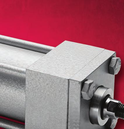
22 The Sheffer Advantage Sheffer Cylinders are Better Cylinders The performance you expect from a quality cylinder Longer lifetime of service Minimal downtime Fast and easy installation Simple, affordable repairs No special tool required to make repairs Lower operating cost More options available Our Cylinders are Designed with the End User in Mind Studded Rod End (Standard, except on C20 Series) Sheffer s rod end design virtually eliminates rod end breakage! The rod ends of many competitive cylinders are cut from the piston rod, creating a weak point at the threads. Our studded connection routes stress factors away from this weak point, so rod-end failure is nearly impossible. Also, rod ends can be replaced without changing the entire piston rod, thereby reducing downtime and repair costs. Four Full Wrench Flats (Standard on all Sheffer cylinders) For convenience, time and money savings during cylinder installation or replacement, Sheffer cylinders are produced with four full wrench flats. With our design, a flat is always positioned for a good wrench hold with normal tools. Our cylinders come this way because unconventional tools and methods are often used when a wrench flat isn t convenient possibly marring the rod surface which can damage seals and cause leaks. Removable Rod Gland (Not available on select small bore cylinders) The wiper and pressure seals on Sheffer cylinders are encapsulated behind a removable rod gland that is bolted to the front of the cylinder. On line changing of seals is fast and easy using normal tools, without disturbing torque settings, removing the rod bearing or tearing down the cylinder. This feature dramatically increases productivity by reducing downtime and repair costs. Separate Rod Bearing (Standard on most Sheffer cylinders) On Sheffer cylinders, the rod bearing is a hydrodynamic flooded bearing, which greatly reduces wear and extends part life. It s also inboard from the seals and a separate component, so if changeout is needed, the seals need not be replaced and vice versa. No special tools are required. Moreover, the rod bearing can be removed and replaced without having to loosen tie rods or tear down the cylinder. That saves downtime, plus the cost of parts and labor. Chamfered Tube Ends (Standard on most Sheffer cylinders) A small angle, or chamfer, is machined into the end of each Sheffer piston tube for quick, easy and reliable repairs. If the piston and rod have been removed (to replace seals for example), when the piston is pushed back in, the chamfer physically compresses the seal into the piston like a built-in funnel. Special compression tools aren t needed during assembly and chances of seal damage are minimized. The chamfer design also prohibits extrusion of the O-ring once the tie rods are tightened. This forms a superior seal and diminishes the chance of leakage at the head and cap joint. Slipper Piston Seal & Bearing (Standard on all hydraulic cylinders) The slipper piston seal and bearing on Sheffer cylinders are a standard option, not a cost-additive feature other manufacturers offer when their designs are inadequate. Our Teflon -based surfaces are an excellent lubricant, demonstrating a very low coefficient of friction with low heat. As the cylinder moves back and forth, the Teflon also migrates into the pores of the cylinder tube, creating an even better lubricating surface. Slipper seals and bearings another reason Sheffer cylinders reduce costs and downtime while increasing productivity. A-21
AS/ASH SERIES ALUMINUM PNEUMATIC AND HYDRAULIC CYLINDERS... 6
 AS/ASH SERIES ALUMINUM PNEUMATIC AND HYDRAULIC CYLINDERS............. 6 Section 6 8 ORDERING INFORMATION For Rod End Dimensions see back cover foldout... Basic Cylinder No Mount.0" to 4.00" For pressure
MA SERIES. Medium-Duty Pneumatic Cylinders Pressure Rating 200 PSI
 MA SIS Medium-Duty Pneumatic Cylinders Pressure ating 200 PSI Construction DIMNSIONALL INTCHANGABL TO MT ANSI SPCIFICATIONS 1,2 Head & Cap High strength aluminum alloy is used for both head and cap. They
ASP Series Steel Body NFPA Cylinder Line
 Series Steel Body NFPA Cylinder Line www.numatics.com Table of Contents Series Features and Benefits 3 Standard Mounts 4 How to Order 5 Port Size Availability 6 Dimensions 7-34 Rod Ends 7 Large Bore 8
HYDRAULIC HEAVY DUTY
 Catalog #HHD-16 12/16 HYDRAULIC HEAVY DUTY Series HHD 3000 PSI RATED 10-25-16 WARNING IMPROPER SELECTION, IMPROPER USE OR FAILURE OF THE PRODUCTS AND/OR SYSTEMS DESCRIBED HEREIN CAN CAUSE PROPERTY DAMAGE,
PL-2 Series Medium-Duty Industrial Hydraulic Cylinders BPL-2 PH-2 PH-3 PHX
 PL- Series Medium-Duty Industrial Hydraulic Cylinders PHX PH- PL- PH- Contents Features... Specifications / Mountings... Design Features and enefits... - Mounting Information, " to " ore Sizes... 8- Mounting
Miller JV Series. Medium Duty Hydraulic Cylinders. Up to 1000 PSI Bore Sizes 1" through 8" 18 Mounting Styles. Catalog M September, 2011
 Medium Duty Hydraulic Cylinders Catalog M0- September, 0 Up to 000 PSI ore Sizes " through " Mounting Styles AV Series Cylinders Up to 0 PSI Permanently Lubricated AL Series Aluminum Cylinders Up to 0
SERIES MH (NFPA) CYLINDER
 CYLINDER") MH SERIES TAB 58 Floating Rod Bushing SELF ALIGNMENT FEATURE Rod Bushing is designed to float.002 to improve bearing surface alignment. SERIES MH (NFPA) CYLINDER Reduces cylinder drag and erratic operation
MH SERIES TAB 58 Floating Rod Bushing SELF ALIGNMENT FEATURE Rod Bushing is designed to float.002 to improve bearing surface alignment. SERIES MH (NFPA) CYLINDER Reduces cylinder drag and erratic operation
PURAKAL SERIES 100 TABLE OF CONTENTS
 TABLE OF CONTENTS How to Order Cylinder......................... Repair Kit......................... Seal Kit......................... Warranty......................... Parts List.........................
MEDIUM DUTY HYDRAULIC NFPA STYLE 1 1/2 TO 8 BORE AIR 250 PSI HYDRAULIC 1500 PSI
 AIR CYLINDERS & MEDIUM DUTY HYDRAULIC NFPA STYLE 1 1/2 TO 8 BORE AIR 250 PSI HYDRAULIC 1500 PSI CONSTRUCTION FEATURES 1. Rod Wiper Urethane 90A 65 to +220F, large cross section lip type wiper designed
Hydraulic Cylinder NFPA Industrial Type
 Hydraulic Cylinder NFPA Industrial Type RA 7038/08.3 Replaces: 0.3 /44 Model CDT/CGT Series X Nominal pressure: Up to,500 psi maximum Table of contents Features Contents Page Duty, up to,500 psi (see chart
HYDRAULIC CYLINDERS NFPA STYLE 1 1/2 TO 8 BORE HYDRAULIC 3000 PSI
 HEAVY DUTY HYDRAULIC CYLINDERS NFPA STYLE 1 1/2 TO 8 BORE HYDRAULIC 3000 PSI CONSTRUCTION FEATURES 1. Rod Wiper Urethane 90A 65 to + 220F, large cross section lip type wiper designed to protect the bearing
Medium Duty 1.5 ~ 4 Bore 12 Different NFPA Mounting Options Non-Rotating Option Tandem Cylinder Option Auto Switch Capable
 N304 Air Cylinder NCA1 Series NFPA Interchangeable Medium Duty 1.5 ~ 4 Bore 12 Different NFPA Mounting Options Non-Rotating Option Tandem Cylinder Option Auto Switch Capable NFPA Interchangable Air Cylinder
FULL COLOR TAB #1 TA 7
 FULL COLOR TAB #1 TA 7 TA - How to Order Floating Rod Bushing SELF ALIGNMENT FEATURE Rod Bushing is designed to float.00 to improve bearing surface alignment. SERIES TA (NFPA) CYLINDER Reduces cylinder
Series 83. Stainless Steel Mini Cylinder
 Stainless Steel Mini Cylinder Magnet included in 7/8 and 1-1/4 bore only in double acting cylinder THEORETICAL CYLINDER FORCE (LBS). Operating Pressures (PSI) Size Action 25 50 75 100 125 150 3/4" Out
SERIES PSI 5000 PSI NON SHOCK HYDRAULIC CYLINDER PURAKAL CYLINDERS, INC PURAKAL CYLINDERS, INC
 CYLINDERS, INC SERIES 3000 3000 PSI 5000 PSI NON SHOCK PURAKAL 1234 345 4567 6789 8901 0123 23 PURAKAL 1234567 HYDRAULIC CYLINDER PURAKAL CYLINDERS, INC P.O. Box 22038 1017 S.Danebo Ave. Eugene, OR 97402-0414
HH SERIES: HEAVY DUTY INDUSTRIAL HYDRAULIC TRD BIMBA. company
 HH SERIES: HEAVY DUTY INDUSTRIAL HYDRAULIC TRD a BIMBA company The TRD difference... Precision machined throughout. We started in business as precision machinists. Every component is machined in a manner
SERIES HH (NFPA) CYLINDER
 CYLINDER") HH SERIES TAB 5 Floating Rod Bushing SELF ALIGNMENT FEATURE Rod Bushing is designed to float.002 to improve bearing surface alignment. SERIES HH (NFPA) CYLINDER HH Rod Lock Reduces cylinder drag and erratic
HH SERIES TAB 5 Floating Rod Bushing SELF ALIGNMENT FEATURE Rod Bushing is designed to float.002 to improve bearing surface alignment. SERIES HH (NFPA) CYLINDER HH Rod Lock Reduces cylinder drag and erratic
Series AM/MM/WM Mill Type Cylinders
 ET AH To order this part, call Lifco Hydraulics USA Toll Free at -00-- S S ZE* SS* SW (TYP) FB THRU, () PLACES TE UF WA / EE P* ØE EE P* CD 00 M CW S Series AM/MM/WM Mill Type Cylinders Table of Contents
SERIES PSI OPERATING PRESSURE HEAVY HYDRAULIC DUTY CYLINDER HEAVY DUTY HYDRAULIC CYLINDER PURAKAL CYLINDERS, INC CYLINDERS, INC
 CYLINDERS, INC SERIES 2500 3000 PSI ORATING PRESSURE HEAVY DUTY HEAVY HYDRAULIC DUTY CYLINDER HYDRAULIC CYLINDER PURAKAL CYLINDERS, INC PURAKAL P.O. Box 22038 CYLINDERS, INC P.O. Eugene, Box OR 22038 97402-0414
Mobile Cylinder Div. Standard Build Series. Catalog HY /US Rev C
 Mobile Cylinder Div. Standard Build Series Catalog HY18-0014/US Rev C WARNING - USER RESPONSIBILITY FAILURE OR IMPROPER SELECTION OR IMPROPER USE OF THE PRODUCTS DESCRIBED HEREIN OR RELATED ITEMS CAN CAUSE
SERIES TA (NFPA) CYLINDER
 CYLINDER") Floating Rod Bushing SELF ALIGNMENT FEATURE Rod Bushing is designed to float.00, improving bearing surface alignment. SERIES (NFPA) CYLINDER Reduces cylinder drag and erractic operation Reduces cylinder
Floating Rod Bushing SELF ALIGNMENT FEATURE Rod Bushing is designed to float.00, improving bearing surface alignment. SERIES (NFPA) CYLINDER Reduces cylinder drag and erractic operation Reduces cylinder
Air/Oil Tanks Air Boosters Cylinder Options Multi-Stage Triple-Rod Basic Cylinders Accessories Technical Data TRA HOW TO ORDER: SERIES TRA (TRIPLE PIS
 SERIES TRA TRIPLE ROD NEW HEAVY-DUTY TRIPLE ROD DESIGN TRD s TR Series has been redesigned. The new series, TRA is a Heavy-Duty version of the TR Series. The new series is a drop-in replacement of the
Series MH MH13 ISO MX1 ISO MX3 ISO MX2 MH12 MH10 MH36 MH35 MH42 ISO ME5 ISO ME6 ISO ME2 MH62 MH64 ISO MP1 ISO MP5 ISO MP3 MH61 MH72
 Series MH MH MH2 MH ISO MX ISO MX ISO MX2 MH MH MH ISO M ISO M ISO M2 MH MH2 MH ISO MP ISO MP ISO MP MH MH2 MH ISO MT ISO MT2 ISO MT Double Rod nd NPA MDX Milwaukee Cylinder Series MH ISO Metric Hydraulic
HH SERIES. Heavy-Duty Hydraulic Cylinders Pressure Rating 3,000 PSI
 HH SRIS Heavy-Duty Hydraulic Cylinders Pressure Rating 3,000 PSI Construction 3 Piston Rod Piston rods through 4" diameter have a minimum expected yield of 00,000 psi. They are case hardened to 50 Rockwell
TaskMaster Pneumatic Cylinder
 TaskMaster Pneumatic Cylinder Index TaskMaster Cylinders Index Air to 200 psi, 1-1/2" thru 6" Bore Page 1-1/2" thru 4" Bore Features & Specifications 2 (profile version) How to Order 3-5 Mounting Styles
FLUID POWER COMPONENTS & SYSTEMS
 FLUID POWER COMPONENTS & SYSTEMS Page Thank you for your interest in Motion Controls LLC. We have been building high quality air and hydraulic cylinders for 50 years in the USA. Motion Controls LLC is
2A Tie Rod Cylinders NFPA Pneumatic Cylinders for working pressures up to 18 bar. Catalogue HY /UK October 2006
 A NFPA Pneumatic Cylinders for working pressures up to bar Catalogue HY0-090/UK October 00 Catalogue HY0-090/UK Mounting Styles A Cylinder Mounting Styles The standard range of Parker A cylinders comprises
Cylinders HD1 Cylinders
 Cylinders HD Cylinders Cylinders For Abusive Conditions Operating Parameters Reference Control Valves Cylinders Specialty Valves Production Devices Index Combining NFPA dimensional interchangeability and
CATALOG FL-16-B THE LIGHT-WEIGHT LINE WITH HEAVY-DUTY FEATURES
 HEAVY-DUTY CATALOG FL-6-B THE LIGHT-WEIGHT LINE WITH HEAVY-DUTY FEATURES TABLE OF CONTENTS CYLINDER FEATURES DOUBLE-ACTING Series T, TS, TL and TLS 4 DOUBLE-ACTING DOUBLE-ENDED Series TDE and TSDE 4 MAGNETIC
HEAVY DUTY PNEUMATIC CYLINDERS
 HEAVY DUTY PNEUMATIC CYLINDES Features: Conforms to ISO:30 standard. Double Acting, with adj. cushioning at both ends. Sizes: Ø, Ø, Ø, Ø, Ø, Ø0, Ø1, Ø0, Ø0 & Ø0. : Other bore sizes on request Seamless
JIT Cylinders A Series Catalog
 JIT Cylinders A Series Catalog Table of Contents Introduction to Excellence Introduction Page 1 Model Code 2 Cylinder Cross Section 3 Feature, Advantages, Benefits 4 Application Data 5 Cylinder Options
250 psi rating. series. pneumatic cylinders. bulletin 0606ST.
 20 psi rating series ST pneumatic cylinders bulletin 0606ST www.royalcylinders.com i Contents Page Description 1 Mounting Styles 2 Features Description Mounting dimensions 3 STNM No Mount (MX0) 3 STME
TABLE OF CONTENTS CYLINDER FEATURES MOUNTING STYLES DOUBLE-ACTING Series T and TS 4 DOUBLE-ACTING DOUBLE-ENDED Series TDE and TSDE 4 MAGNETIC SWITCH D
 HEAVY-DUTY CATALOG FL-6-A FLAIRLINE FAST Shipped in - days THE LIGHT-WEIGHT LINE WITH HEAVY-DUTY FEATURES TABLE OF CONTENTS CYLINDER FEATURES MOUNTING STYLES DOUBLE-ACTING Series T and TS 4 DOUBLE-ACTING
LP/LPM Series. Non-Lube Air Cylinder P1M. Tooling Plate P1M. Swing Clamp P1M. Contents E51
 Non-Lube Air Cylinder P1G C05(S) LP(M) Swing Clamp Tooling Plate Contents Features...52 Ordering Information...53 Specifications...54 Basic Dimensions...55 Mounting Options...56 Spring Data...57 Rod Options...58
Parker Series 2A Air Cylinder
 Parker ir ylinder hen the job calls for reliable, heavy-duty performance, specify. 00,000 psi yield strength chrome-plated, case-hardened piston rod.,000 psi yield strength rod-end stud with rolled threads.
Tie-rod Cylinders, ISO 6431, ISO compliant Series 60
 Tie-rod Cylinders, ISO 6431, ISO 15552 compliant Series 60 Single or double-acting, magnetic, cushioned Standard and low friction versions ø 32, 40, 50, 63, 80, 100, 125 mm In compliance with ISO 15552
HPI Cylinders. Manufacturers of Hydraulic & Air Cylinders Since 1946
 HPI Cylinders Manufacturers of Hydraulic & Air Cylinders Since 1946 Cylinder Catalog 2018 HPI Cylinders www.hpicylinders.com Since 1946 Main Plant 13766 Milroy Place Santa Fe Springs, CA 90670 Phone (800)
Cylinders Small Bore Tie Rod
 Cylinders Small Bore Tie Rod Reference Control Valves Cylinders Specialty Valves Production Devices Index Cylinder Materials Heads: Tubes: Piston: Rod: Bearing: Piston and Rod Seals: Rod Wiper: Tie Rods:
NFPA Double acting imperial cylinders
 > > Ø 4... 8 > > Adjustable captive cushion needle > > Constructed of the finest materials > > Magnetic piston standard > > Wide temperature range > > Shock and vibration tested to N 61373, Category 1,
CYLINDERS OPTIONS ACCESSORIES
 CYLINDERS NFPA Interchangeable 1.50 thru 1 Bores 50 PSI Pneumatic Strokes to 10 Inches Permanent Lubrication Temperatures: 00 F Standard Double Acting Multi-Stage Multi-Position Triple Rod Flush Mount
The Lehigh Miracalube Air Cylinder The Only Real Self-Lube Air Cylinder in the World BENEFITS!
 SERIES JHD HEAVY DUTY AIR CYLINDER The Lehigh Miracalube Air Cylinder The Only Real Self-Lube Air Cylinder in the World BENEFITS! The true test of a cylinder is how well it performs in your application.
Heavy Duty 3500/5000. psi rating. series. hydraulic cylinders. bulletin 0207XH
 3500/5000 psi rating Heavy Duty series XH hydraulic cylinders bulletin 0207XH www.royalcylinders.com 1 Contents Page Description 1 Contents 2 Features Description Mounting Dimensions 3 C Clevis Mount 3
Extruded Body Cylinders, ISO 6431, ISO compliant Series 61
 1 ISO / VDMA Cylinders NORTH AMERICAN CYLINDER & ACTUATOR CATALOG > Release 8.5 Extruded Body Cylinders, ISO 6431, ISO 15552 compliant Series 61 Single or double-acting, magnetic, cushioned Standard and
AIR AND HYDRAULIC CYLINDERS NFPA INDUSTRIAL TYPE
 AIR AND HYDRAULIC CYLINDERS NFPA INDUSTRIAL TYPE NFPA Industrial Type Cylinders TaskMaster Pneumatic Cylinders (to 200 psi) 1 1/2" - 4" Bores 5" & 6" Bores Profile Design External Tie Rods PowerMaster
Medium Duty Hydraulic Cylinders Series 3L
 Medium Duty Hydraulic ylinders Series L Medium Duty Service Industrial Tie od onstruction Nominal Pressure 000 PSI Depending on ore Size Standard ore Sizes " through " Piston od Diameters /" through -/"
MH SERIES METRIC HYDRAULIC CYLINDERS. Specials are Our Standard. ISO standard 6020/2-160 bar series For working pressures up to 210 bar
 ISO 00 RISTRD Specials are Our Standard MH NPA MX MH NPA MX MH NPA MX2 ISO MX ISO MX ISO MX2 MH SRIS MH MH MH NPA ISO M M NPA ISO M M NPA ISO M2 MS2 MTRIC HDRAULIC CLINDRS MH NPA ISO MS2 MP MH2 NPA ISO
Series MH Hydraulic Cylinders
 Series MH Hydraulic Cylinders Atlas Cylinders Tri-Lip Seal Designed To Eliminate Rod Seal Leakage Atlas Cylinders Series MH Heavy Duty Mill Hydraulic Cylinders with the Tri-Lip seal offers positive protection
Features. when stopping. Various mounting styles. Rod type. Bore size (Heavy Duty) (Standard)
 (Standard)") Features Symbol Standard tie rod type hydraulic cylinder Double acting hydraulic cylinder for 70 kgf/cm 2 or 140kgf/cm 2 with bore sizes from 40 to 250. High performance cushion to reduce shock Double
Features Symbol Standard tie rod type hydraulic cylinder Double acting hydraulic cylinder for 70 kgf/cm 2 or 140kgf/cm 2 with bore sizes from 40 to 250. High performance cushion to reduce shock Double
T-MAC CYLINDERS, INC.
 T-MAC CYLINDERS, INC. HEAVY DUTY ALUMINUM CYLINDERS AND ACCESSORIES HIGH QUALITY, DEPENDABLE, NFPA INTERCHANGEABLE CYLINDERS - MADE IN THE USA. 9014 SWANSON DRIVE ROSCOE, IL 61073 PHONE: 815-877-7090 FAX:
NEN Series NFPA Aluminum Cylinders
 NEN Series NP luminum ylinders 1-1/2" to 4" bore sizes ompetitively priced Magnetic piston standard djustable cushion standard Sleeve nut construction standard Stocked strokes Technical data Medium: iltered
MC105R2 ISO 9001 REGISTERED
 MC0R ISO 900 RISTRD Table Piston Rod nd Styles (Series H, LH and A) See page 0 for Series MN ROD A B -.00 -.00 C CC *D NA AD A +.00 -.00 AF diameter AC / / / / /- / /-0 /-0 9/ / / / / / / / - / /- /- /
Industrial Cylinder Products Hydraulic and Pneumatic Cylinders. Catalog (01/11)
") Industrial ylinder Products Hydraulic and Pneumatic ylinders atalog 00- (0/) Pneumatic ylinders Index Page Series, Heavy Duty, 0 P.S.I. ccessories - vailable Mountings and Specifications ushion Data -
Industrial ylinder Products Hydraulic and Pneumatic ylinders atalog 00- (0/) Pneumatic ylinders Index Page Series, Heavy Duty, 0 P.S.I. ccessories - vailable Mountings and Specifications ushion Data -
Pneumatic Cylinders NFPA Series
 Pneumatic Cylinders NFPA Series INDEX: General characteristics 3 Mounting styles 5 Piston rod characteristics (bore diam 25/150) 6 Single rod cylinder dimensions (bore diam 25/150) 8 Piston rod characteristics
3MA/4MA Series Non-Lube NFPA Air Cylinders
 MA/MA Series Non-Lube NFPA C S MNR MAJ/MAJ ACV MA/MA Contents MA Series -/" to 5" ore... 5-0 MA Series -/" to 5" ore... -5 How to Select a MA or MA Cylinder...6 MA asic Dimensions -/" to 5" ore... 7-8
SUPERIOR CONSTRUCTION FEATURES SERIES B AIR CYLINDERS, 1 2" THRU 2" BORE SIZE MAXIMUM PSI 250
 SUPERIOR CONSTRUCTION FEATURES SERIES B AIR CYLINDERS, 1 2" THRU 2" BORE SIZE MAXIMUM PSI 250 ALUMINUM HEADS & CAPS LARGE PORTS PISTON PACKING PISTON WIPER BRONZE BEARING PACKING TUBE SEAL CYLINDER TUBE
Single and double-acting, magnetic, cushioned Standard, low friction, low temperatures and tandem versions ø 32, 40, 50, 63, 80, 100, 125mm
 CATALOGUE > Release 8.8 > Series 60 cylinders Series 60 cylinders Single and double-acting, magnetic, cushioned Standard, low friction, low temperatures and tandem versions ø 32, 40, 50, 63, 80, 00, 25mm»»
AIR CYLINDER Series A25, A26
 A25 - Magnetic A26 - Non-magnetic S Double End Double Acting - Ø32-100 mm As per ISO 15552 / VDMA 24562 standards Features Adjustable cushioning at both ends with elastomer pads Wide varieties of mountings.
Single and double-acting, magnetic, cushioned Standard, low friction and low temperature versions ø 32, 40, 50, 63, 80, 100, 125mm
 CATALOGUE > Release 8.6 > Series 60 cylinders Series 60 cylinders New version Single and double-acting, magnetic, cushioned Standard, low friction and low temperature versions ø 32, 40, 50, 63, 80, 00,
Bore ø 32, 40, 50, 63, 80, 100, 125 Ports 32 = 1/8, 40/50 = 1/4, 63/80 = 3/8, 100/125 = 1/2
 6 S E R I E S Cylinders Series 6 Catalog 2006 Single, double acting, magnetic (DIN/ISO 643) Bore: ø 32, 40, 50, 63, 80, 00, 25 cushioned [ /4, 9/6, 2, 2 /2, 3 /8, 4, 5 inch approximations] The Series 6
Series MH Heavy Duty Mill Hydraulic Cylinder
 Heavy Duty Mill Hydraulic Cylinder Catalog HY0--/NA May, 00 n Meets All NFPA Mounting Dimensions n Heavy Duty Service Mill Type Construction n Nominal Pressure 000 PSI n Standard Bore Sizes -/" through
ISO 6020/2 industricylindre Industrial cylinders
 According to ISO 6020/2 1991 DIN 24554, compact series 160 bar Working pressure up to 21 Mpa Maximum pressure 25 Mpa Working temperature 20 to 80 C Stroke tolerance 0 to 1.2mm for strokes up to 1000mm,
Series AHM Metric Hydraulic Cylinder
 Series AHM Metric Hydraulic Cylinder As a major supplier of pneumatic and hydraulic cylinders, Atlas Cylinders introduces the Series AHM metric hydraulic cylinder. Atlas Series AHM cylinders are designed
Series LAA Industrial Interchangeable Pneumatic Cylinders. Catalog LAA-1 05/00
 Series L Industrial Interchangeable Pneumatic ylinders atalog L- 0/00 Model Numbers Lin-ct Series L Series L Model Numbers How to Develop Them How to Decode Them Lin-ct Series L cylinders can be completely
7" & 8" Bore High Pressure zhc03 Hydraulic Cylinders Series 3H
 7" & " ore High Pressure zhc0 Hydraulic ylinders Series H Heavy Duty Service Industrial Tie-od onstruction Nominal Pressure 000 PSI Fifteen Standard Mounting Styles For ylinder Division Plant Locations
Electronic Stroke Positioning Cylinders Series ES Series EM Series EP
 Electronic Stroke Positioning Cylinders Series ES Series EM Series EP Catalog ESP00 November, 00 Atlas Cylinders Tri-Lip Seal Designed To Eliminate Rod Seal Leakage Atlas Cylinders Series ES, EM, EP Hydraulic
Aluminium profile. TANDEM: Double thrust and traction forces. LOW FRICTION: Friction force reduced by over 40%
 CATALOGUE > Release 8.7 > Series 6 cylinders Series 6 cylinders - Aluminium profile Single and double-acting, magnetic, cushioned Standard, low friction, low temperatures and tandem versions ø 32, 40,
AIR CYLINDER Series A12, A13
 A12 - Non magnetic A13 - Magnetic S Double Acting ( Ø32-100 ) mm As per ISO 6431 / CETOP RP43P, RP53P standards Features Adjustable cushioning at both ends Wide varieties of mountings Low friction Long
Series OCG Pneumatic Cylinders
 New Models The Price Alternative Series OCG Pneumatic Cylinders www.phdinc.com (8) 624-811 and Rebuildable round body cylinders 6 bore sizes standard stroke lengths High speed/double acting OCG2 ORDERING
2A Pneumatic Cylinders
 A Pneumatic Cylinders Steel-bodied tie rod cylinders for working pressures up to bar Mounting Styles A Cylinder Mounting Styles The standard range of Parker A cylinders comprises mounting styles, to suit
Double acting, cushioned, magnetic Ø mm
 CATALOGUE > Release 8.7 > Series 40 cylinders Series 40 cylinders Double acting, cushioned, magnetic 60-200 - 250-320 mm In compliance with ISO 5552 standards and with the previous DIN/ISO 643 - VDMA 24562
Medium Duty Hydraulic Cylinders. Series 3L
 Medium Duty Hydraulic Cylinders Series L Catalog HY08-0-6/NA Series L In line with our policy of continuing product improvement, specifications and information contained in this catalog are subject to
Metric Hydraulic Cylinders Series HMI
 Series HMI Conforms to ISO 600/ (99) or working pressures up to 0 bar Vital Technologies for Motion and Control or Cylinder Division Plant Locations See Page II. 05 As the world leader in the design and
AIR CYLINDER Series A75, A76
 A76 - n-magnetic A75 - Magnetic AIR CYLINDER Round s - Ø32, 40, 50 and 63 mm Double Acting with Adjustable Cushioning Features Available in magnetic and n magnetic version Adjustable cushioning at both
AIR CYLINDER Series A23, A24
 A23 - Magnetic A24 - Non-magnetic Double Acting s (Square type) Ø32-125 mm As per ISO 15552 / VDMA 24562 standards. Features Adjustable cushioning at both ends with elastomer pads Wide varieties of mountings
PowerMaster NFPA Pneumatic Cylinders Index
 PowerMaster NFPA Pneumatic Cylinders Index PowerMaster NFPA Pneumatic Cylinders Index Air to 200 psi, 1-1/2" thru 14" Bore Page Features & Specifications. 1.48-1.49 Options and Modifications 1.50-1.52
Cylinders. HD1 Cylinders. Customize Your Cylinder. Viton Seals (VI) Cushions (CR, CF, CB) Low Breakaway Option (NL) Magnetic Piston (MP)
 Cushions (CR, CF, CB) Low Breakaway Option (NL) Magnetic Piston (MP)") HD Cylinders Cylinders Customize Your Cylinder The HD Series offers numerous accessories and design options. With hundreds of possible combinations available, you can design your own cylinder for any application.
HD Cylinders Cylinders Customize Your Cylinder The HD Series offers numerous accessories and design options. With hundreds of possible combinations available, you can design your own cylinder for any application.
The friction free alternative
 Rolling The Rolling Diaphragm Air Cylinder The advent of the long stroke rolling diaphragm as a means of low-friction dynamic sealing has led to the development of the ControlAir Diaphragm Air Cylinder.
AL4 Series Air Cylinder
 L Series ir ylinder atalog M097- February, 00 Up to 0 PSI Bore Sizes -/" through 8" NFP Interchangeable 7 Standard Mounting Styles Series ylinders Up to 0 PSI Permanently lubricated BT & BTM Series ylinders
wiper seal keeps contaminates from getting into cylinder by aggressively wiping foreign materials from the piston rod, enhancing the rod seal life.
 CTUTORS NFP Series luminum & J Steel Cylinders 1-1/2 to 12 inch bore size Impact dampening seals djustable captive cushion needle Ecology cylinders meet OSH noise standards Constructed of the finest materials
Aluminium profile. Double-acting, cushioned, magnetic ø mm
 > Series 4 cylinders Series 4 cylinders - Aluminium profile Double-acting, cushioned, magnetic ø 60-200 mm»» In compliance with ISO 643/ VDMA 24562 standards»» Rolled stainless steel rod»» Adjustable pneumatic
Round Body Minicylinders, DIN/ISO 6432 Series 16, 24 and 25
 Round Body Minicylinders, DIN/ISO 6432 Series 16, 24 and 25 Series 16: ø 8-10 - 12 bumpers Series 24: ø 16-20 - 25 bumpers and magnetic piston Series 25: ø 16-20 - 25 adjustable cushion and magnetic piston»»
E Series Economic Tie-Rod Cylinder Line
 Series Economic Tie-Rod Cylinder Line www.numatics.com Table of Contents E Series Features and Benefits 3 How to Order 4 Basic E-Series Cylinders 5 Cushioned Cylinders 5 Basic E-Series Dimensions 5 E-Series
Aluminium tube and profile
 > Series 63 cylinders CATALOGUE > 206 Series 63 cylinders - Aluminium tube and profile New Single and double-acting, magnetic, cushioned Versions: standard, low friction, high and low temperatures ø 32,
Optimized for OEM requirements at a lower price.
 The Price Alternative Optimized for OEM requirements at a lower price. Series OSH Compact Pneumatic Slide Table - 4 s, Incremental Travels Series ORQ Compact Rotary Table - 6 s Series OCV Pneumatic ISO
Linear Thrusters/PneuMoment
 /PneuMoment Extruded TE Series 3.3-3.10 3.11-3.16 T Series Multiple Position T4 Series Movable Housing 3.17-3.22 3.23-3.24 3.25-3.28 3.29-3.32 Pneu-Moment Checklist PneuMoment Pneumatic Actuators PneuMoment
SC series Stopper Cylinders
 SERIES 60,000 PSI tensile strength electro-less nickel rod bearing High strength threaded connection Hard chrome plated 100,000 PSI yield strength rod inc plated dust cover series Stopper Cylinders Common
SC series Stopper Cylinders
 High strength threaded connection Low friction cup sealintegral rod wiper Double wound 302 SS retaining wire 60,000 PSI tensile strength electro-less nickel rod bearing Low friction figure 8 piston seal
E Series Economic Tie-Rod Cylinder Line
 E Series Economic Tie-Rod Cylinder Line w w w. n u m a t i c s. c o m Table of Contents E Series Features and Benefits 3 How to Order 4 Basic E-Series Cylinders 5 Cushioned Cylinders 5 Basic E-Series Dimensions
Series VH Hydraulic Cylinders
 Series H Series H very heavy-duty hydraulic cylinders are premium quality cylinders with operating capacities of,000 PSI. They fully meet NPA standards. And to make sure every cylinder is premium-quality,
Double-Wall Cylinders/Repairable Stainless Steel Cylinders
 Double-Wall Cylinders/Repairable Stainless Steel Cylinders Double-Wall Cylinders 6.3-6.15 Repairable Stainless Steel Cylinders 6.16-6.24 DW/RSS Cylinders Bimba Double-Wall Cylinders The Bimba Double-Wall
SMS Solid Stainless Cylinders
 SMS Solid Stainless Cylinders Space Saving and Conventional Lengths Pneumatic to 200 PSI Hydraulic 400 to 500 PSI Non shock /8, /2, 2, 3 Bore 300 Series Stainless Exterior Assures Aesthetics and Function
PH-3 Series 10" - 20" Bore Heavy-Duty Industrial Hydraulic Cylinders BPL-2 PH-2 PH-3 PHX
 PH- Series 0" - 0" ore Heavy-Duty Industrial Hydraulic Cylinders PHX PH- PL- PH- Contents Features...06 Specifications and Mountings...0 Design Features...0-09 Mounting Information...0- Double Rod Models...
SMS Solid Stainless Cylinders
 SMS Solid Stainless Cylinders Space Saving and Conventional Lengths Pneumatic to 200 PSI Hydraulic 400 to 500 PSI Non shock /8,, 2, 3 Bore 300 Series Stainless Exterior Assures Aesthetics and Function
MULTIPOSITION AIR CYLINDER
 MULTIPOSITION AIR CYLINDER CAST ALUMINUM FOUR-POSITION - ALL AIR SERVICE INFORMATION MOUNTING! Devices should be mounted and positioned in such a manner that they cannot be accidentally operated. INSTALLATION
RT Series Roundline Plus Thrusters
 9/16" to 3" bore Composite and Roller Bearings PS magnetic piston option Optional ecology seal Optional shock absorbers Choice of high load composite or precision low friction bearings Comes with stroke
Series 6PF Positioning Feedback cylinders 1/ Double-acting low friction, magnetic ø 50, 63, 80, 100, 125 mm
 CATALOGUE > Release 8.8 > Series 6PF cylinders Series 6PF Positioning Feedback cylinders Double-acting low friction, magnetic ø 50, 63, 80, 00, 25 mm»» In compliance with ISO 5552 standards and with the
Linear Thrusters/PneuMoment
 /PneuMoment Extruded TE Series (Composite Bearings) 3.3-3.10 3.11-3.16 T Series Multiple Position T4 Series Movable Housing 3.17-3.22 3.23-3.24 3.25-3.28 3.29-3.32 Pneu-Moment Checklist PneuMoment Pneumatic
V160C. Mould Hydraulic Systems. Hydraulic cylinders-iso 6020/2 compact 160 bar V160C
 V160C Mould Hydraulic Systems Hydraulic cylinders-iso 6020/2 compact 160 bar V160C V160Ccat.GB01-2006 Hydraulic cylinders-iso 1 2 Chrome-plated steel rod, hardened or tempered and polished. Thickness of
Accessories Air/OilTanks Switches Clevis&Brackets AirBoosters AlignmentCouplers. Sensors
 Air/OilTanks Clevis&Brackets AirBoosters AlignmentCouplers Sensors On time,consistentdelivery.everycustomer sorderisimportant.ourbusinesismanaged solargeordersdonotdisruptourpublisheddeliveryschedules.
Series ICS and ICL Pneumatic Cylinders. Corrosion resistant stainless steel and aluminum cylinders
 Series ICS and ICL Pneumatic Cylinders Corrosion resistant stainless steel and aluminum cylinders Series ICS and ICL cylinders New generation of stainless steel and clean line cylinders. Series ICS from