HEAVY DUTY SS STAINLESS STEEL CONSTRUCTION
|
|
|
- Gyles Curtis
- 5 years ago
- Views:
Transcription
1
2

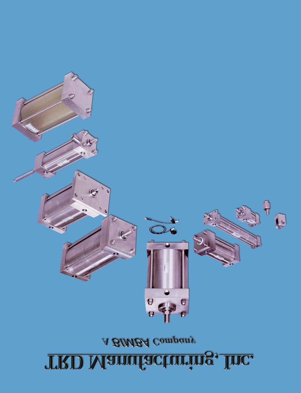
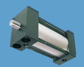
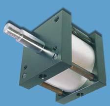
3 HEAVY DUTY SS STAINLESS STEEL CONSTRUCTION Ideal for: Food Processing Applications Chemical, Medical or Pharmaceutical Offshore or Marine Equipment Energy Production or Waste Treatment Floating Rod Bushing SELF ALIGNMENT FEATURE Rod Bushing is designed to float.00, improving bearing surface alignment CUSTOMER EQUIPMENT CYLINDER BUSHING CYLINDER PISTON Reduces cylinder drag and erratic operation Reduces cylinder wear Provides longer life than fixed Rod Bushing designs ÆPISTON Precision machined from 0-T alloy aluminum, provides an excellent bearing surface for ÀFLOATING BUSHING Precision machined from extended cylinder life. (Optional: Stainless Steel with 0 stainless steel, extra-long PTFE composite wear PTFE wear band) band for extended service. ÇTIE S Drawn and ground 0 high strength ÁHEAD, CAP & RETAINER 00% Precision machined stainless steel, rolled threads for maximum strength. from highly corrosion resistant 0 stainless steel bar for ÈACORN NUTS 0 Stainless steel, eliminates exposed tough and corrosive environments. threads for food grade applications. ÂCYLINDER TUBE Precision machined and honed from ÉCUSHIONS (Options H & C) Floating cushion seal 0 stainless steel, providing smooth consistent designed for maximum cushion performance, quick operation. return stroke break-away and extended life. ÃPISTON Drawn, ground and polished high yeild CUSHION ADJUSTMENT NEEDLE - 0 stainless steel 0 stainless steel, Hard Chrome plated. design has fine thread metering and is positively ÄPISTON & SEALS Heavy lip design Carboxilated captured to prevent needle ejection during adjustment. Nitrile construction. Seals are pressure activated and LUBRICATION - Permanently lubricated with Magnawear compensating for long life. Lube G PTFE based grease on all internal components. Å WIPER PTFE scraper design for maximum This lubricant is a non-migratory type high performance compatibility with wash-down and chemical solutions grease, providing outstanding service for life. (FDA approved material). (no additional lubrication is required) OPERATING PRESSURE 0 PSI AIR (7 BAR) 00 PSI Hydraulic (7 BAR) ( TH Option) OPERATING TEMPERATURE Carboxilated Nitrile: -0 F to 00 F (- C to 90 C) Fluorocarbon: 0 F to 00 F (-0 C to 00 C) PERFORMANCE OPTIONS: FDAL: DRB: VS: SSP: FDA approved lubricant, rated for 0 F to 00 F (-0 C to 0 C) Solid Delrin Rod Bushing (FDA approved) for extra long life under high pressure wash-down applications. This bearing material requires ZERO lubrication due to self lubricating properties. Fluorocarbon seals provide a higher chemical resistance to most wash-down solutions. Solid Stainless Steel Piston provides maximum corrosion resistance and FDA approval for food contact. (PTFE wear band standard) REFER TO PAGES thru 7 FOR MORE OPTIONS & CYLINDER DESIGNS
4 Switches Accessories Cylinder Options Non-Rotating Basic Cylinders SS SERIES 0 PSI AIR SEE PAGE TO ORDER SS-MS SERIES (MULTI-STAGE) MXO MP MP MT MT MX MX MX MF MF ME ME MS MS NFPA MOUNTS NO MOUNT ( - BORE) REAR PIVOT CLEVIS ( - BORE) REAR PIVOT EYE ( - BORE) FRONT TRUNNION ( - BORE) REAR TRUNNION ( - BORE) EXTENDED TIE-S (HEAD & CAP) ( - BORE) EXTENDED TIE-S (CAP) ( - BORE) EXTENDED TIE-S (HEAD) ( - BORE) FRONT FLANGE ( - BORE) REAR FLANGE ( - BORE) FRONT MOUNTING HOLES ( BORE) REAR MOUNTING HOLES ( BORE) SIDE LUG ( - BORE) BOTTOM TAPPED HOLES ( - BORE) About our Part Number System Simple, easy to understand No excessive codes Eliminates mistakes when ordering EXAMPLE: A Stainless Steel cylinder with a Bore, 0 Stroke, Front Flange Mount, Head and Cap Cushion Part Number: SS-MF- X 0-HC SERIES SS : HOW TO ORDER SS - MX0 - X - HC - BP - KK - MPR - OP = PORTS AT & 7 CUSHIONS H = HEAD CUSHION POSITION STANDARD SPECIFY FOR POSITIONS, OR C = CAP CUSHION POSITION STANDARD SPECIFY FOR POSITIONS, 7 OR STROKE 0 TO 0 MADE TO ORDER BORE,,,,,, STYLE SINGLE (LEAVE BLANK) D = DOUBLE END PORT & CUSHION POSITIONS NFPA MOUNTS MXO MXOD MP 7 MP A / O B** BH** BC** BP A = C = DRB FDAL KK KK KKS KK LF MPR MPH MS NR OP OS SE SR SSP ST TH VS WB AS XX OPTIONS AIR / OIL PISTON URETHANE BUMPER BOTH ENDS URETHANE BUMPER HEAD ONLY URETHANE BUMPER CAP ONLY BUMPER PISTON SEAL ( - BORE) EXTENDED PISTON THREAD (SPECIFY) EXTENDED PISTON (SPECIFY) DELRIN BUSHING FDA APPROVED LUBRICANT INTERMEDIATE MALE THREAD FEMALE THREAD STUDDED PISTON (WITH KK) FULL DIAMETER MALE THREAD LOW FRICTION, 0 PSI AIR MAGNETIC PISTON FOR REED SWITCHES MAGNETIC PISTON FOR HALL SWITCHES METALLIC SCRAPER (BRASS) NON-ROTATING OPTIONAL PORT LOCATION OVERSIZED DIAMETER (SPECIFY SIZE) SPRING EXTEND (CONSULT FACTORY) SPRING RETURN (CONSULT FACTORY) STAINLESS STEEL PISTON (WITH WEARBAND) STOP TUBE (SPECIFY LENGTH) 00 PSI HYDRAULIC, NON-SHOCK FLUOROCARBON SEALS WEAR BAND ON PISTON ADJUSTABLE STROKE (RETRACT) SPECIAL VARIATION (SPECIFY) BSP, SAE PORTS (SPECIFY SIZE) ** BUMPERS ADD PER END TO CYLINDER LENGTH STANDARD PORT AND STANDARD CUSHION AND SPECIFY NON-STANDARD LOCATIONS WHEN ORDERING MT Air/Oil Tanks - Bores - - Page Bores Page 0 Bores Page - Bores Page - Bores Page MT MX MX MX MF Multi-Stage - Bores Page - Bores Page 7 - Bores Page 7 - Bores Page 7 - Bores Page 7 MF ME ME MS MS Technical Data - Bores Page 7 Bore Page 7 Bore Page 7 - Bores Page - Bores Page
5 SERIES SS DIMENSIONS: BAS IC CYL INDER (NO MOUNT) About Rod End Styles Style Male Rod End is STANDARD Other NFPA Styles can be specified (See Chart). Need a rod end not listed? NO PROBLEM Each Piston Rod is made to order and does not delay shipment. Coarse (UNC) threads, Metric threads or just plain rod ends are common. Thread lengths are also made to order (Specify: A =Length). NEED SOMETHING NOT LISTED? Just send us a sketch. In most cases, quotes are turned around in one day PISTON END STYLES STYLE & STYLE STYLE EASY FLIP OUT PAGE FOR REFERENCE BORE,,,, & MM DIAMETER Standard Oversize Standard Oversize Standard Oversize STANDARD Style - Male KK A 7/-0 - / - / Style - Male KK A -0 7/- / 7/- / OPTIONAL Style - Female KK A 7/-0 - / - / Style - Male KK A - - / - / C V () EE NPT B BUSHING DIA. MM DIA. Y P + STROKE DIA. BUSHING RETAINER ( BORE ONLY) KK THDS. A MXO (NO MOUNT) R E SQ. C V F G LB + STROKE J K ZB + STROKE BORE DIAMETER Standard Oversize Standard Oversize Standard Oversize Standard Oversize Standard Oversize Standard Oversize Standard Oversize Standard Oversize A / / / / / / B / / / BASIC DIMENSIONS MXO STANDARD & OVERSIZED S C E EE F G J K KK 7/-0 7/ - 7/-0 9/ - 7/-0 9/ / - - / LB / MM P R V Y 7/ 7/ 7/ ZB / 7/ / 9/ / / 7/ 7 7 7
6 SERIES SS DIMENSIONS: PIVOT MOUNTS MP CLEVIS AND MP EYE MOUNT DIMENSIONS BORE DIAMETER CB CD CW FL L M Standard Oversize Standard Oversize Standard Oversize Standard Oversize Standard Oversize Standard Oversize Standard Oversize Standard Oversize / / / 7/ 7/ 7/ N/A 7/ 7/ 7/ Clevis pin provided with MP and MP mounts. MP bore not available. For dimension not shown see page. TL E (SQ.) UT TL MT / MT MP XC + STROKE HARD CHROME PLATED O.D. WEAR SURFACE ON TRUNIONS TD DIA L CD DIA. (PIN INCLUDED) XG XC 7/ 7/ 7 / 7/ 7 / 7 / 7 / MT MT HEAD TRUNNION AND MT CAP TRUNNION MOUNT DIMENSIONS BORE DIAMETER E TD TL UT XG XJ Standard / Oversize* N/A Standard / Oversize / Standard Oversize / Standard Oversize Standard Oversize Standard 7 Oversize Standard 7/ 9 Oversize 7/ / Standard Oversize 7/ *No oversize rod on bore MT. For dimensions not shown see page. M CW CW CB XD / / 7/ / 9 / N/A N/A Note: Trunnions are bolt on, non-removable design. MP XD + STROKE FL ACCESSORIES (SEE PAGE FOR DIMENSIONS) EYE BRACKET CLEVIS EYE CLEVIS PIN (FOR MP) SS-RC7 SS-RE7 SS-CP00 SS-RC70 SS-RE70 SS-CP70 SS-RC7 SS-RE7 SS-CP00 SS-RC70 SS-RE70 SS-CP70 SS-EB00 SS-RC7 SS-RC70 SS-RC70 SS-RE7 SS-RE70 SS-RE70 SS-CP00 SS-CP70 SS-CP70 SS-RC000 SS-RE000 SS-CP000 SS-RC70 SS-RE70 SS-CP70 SS-RC000 SS-RE000 SS-CP000 SS-EB70 SS-RC70 SS-RC000 SS-RE70 SS-RE000 SS-CP70 SS-CP000 SS-RC000 SS-RE000 SS-CP000 SS-RC0 SS-RE0 SS-CP7 SS-RC000 SS-RE000 SS-CP000 SS-EB000 SS-RC0 SS-RE0 SS-CP7 XJ CD DIA. (PIN INCLUDED) Note: Pivot Mount is non-detachable. Contact factory for detachable mount options. MT ACCESSORIES (SEE PAGE FOR DIMENSIONS) CLEVIS EYE CLEVIS PIN SS-RC7 SS-RC70 SS-RC7 SS-RC70 SS-RC7 SS-RC70 SS-RC70 SS-RC000 SS-RC70 SS-RC000 SS-RC70 SS-RC000 SS-RC000 SS-RC0 SS-RC000 SS-RE7 SS-RE70 SS-RE7 SS-RE70 SS-RE7 SS-RE70 SS-RE70 SS-RE000 SS-RE70 SS-RE000 SS-RE70 SS-RE000 SS-RE000 SS-RE0 SS-RE000 SS-CP00 SS-CP70 SS-CP00 SS-CP70 SS-CP00 SS-CP70 SS-CP70 SS-CP000 SS-CP70 SS-CP000 SS-CP70 SS-CP000 SS-CP000 SS-CP7 SS-CP000 SS-RC0 SS-RE0 SS-CP7 M CB Basic Cylinders Non-Rotating Cylinder Options Accessories Switches Air/Oil Tanks Multi-Stage Technical Data
7 Basic Cylinders SERIES SS DIMENSIONS: TIE & FLANGE MOUNTS DD AA MX DD AA Non-Rotating Cylinder Options Accessories MX TIE EXTENDED MX, MX & MX MOUNT DIMENSIONS BORE DIAMETER Standard Oversize Standard Oversize Standard Oversize Standard Oversize AA BB / / DD - /- /- - FH R Full square bushing retainer on thru bore. * Round retainer on bore. BB dimension from face of head. For dimensions not shown, see page. R BB DD BB AA R FH AA R BB BB R DD FH MX TIE EXTENDED MX, MX & MX MOUNT DIMENSIONS BORE DIAMETER AA BB DD FH R Standard Oversize Standard Oversize Standard Oversize Standard Oversize / / / *..0.. Switches FB HOLES () R E MF MF FB HOLES () R E TF UF W FH W FH ZF + STROKE FH UF TF Air/Oil Tanks DIA. - BORES FB HOLES () 7.7 E ROUND BUSHING RETAINER ME - BORES ME FB HOLES () 7.7 E 7.7 W W ZF + STROKE 7.7 E Multi-Stage Technical Data BORE ONLY MF, MF FLANGE & ME, ME CAP MOUNT DIMENSIONS BORE DIAMETER E FB FH R TF UF W ZF Standard. / Oversize Standard. / Oversize Standard.9 7/ / Oversize Standard 7/.7 / Oversize Full square bushing retainer on thru bore. *Round retainer on bore. For dimensions not shown, see page. BORE ONLY MF, MF FLANGE & ME, ME CAP MOUNT DIMENSIONS BORE DIAMETER E FB FH R TF UF W ZF Standard. 7/ 7/ Oversize Standard 9/.0 7 Oversize Standard. 7 7/ 7 9/ Oversize / 7 Standard / N/A N/A N/A N/A Oversize 7/ 7 7
8 ST SB DIA () SERIES SS DIMENSIONS: BASE MOUNTS TS US SH MS SIDE LUG MOUNT DIMENSIONS BORE DIAMETER SB SH ST SU SW SZ TS US XS Standard 7/ / Oversize Standard 7/ / Oversize Standard 7/ / Oversize Standard 7/ 9/ 7/ Oversize / Standard 7/ 9/ Oversize / Standard / / / / 9/ 7/ Oversize / Standard / / / / / 7 7/ 9 Oversize 9/ Standard / / 9/ / / 9 7/ Oversize 9/ Full square bushing retainer on thru bore. Round retainer on bore. For dimensions not shown, see page. TN E/ NT TAP () TK DEEP BORE DIAMETER E/ Standard Oversize Standard Oversize Standard Oversize Standard Oversize 7/ Standard Oversize Standard Oversize Standard Oversize Standard Oversize Full square bushing retainer on thru bore. Round retainer on bore. For dimensions not shown, see page. SW XS XT SU MS BOTTOM TAP MOUNT DIMENSIONS NT -0 / TK / / TN 7/ / / MS SS + STROKE MS SN + STROKE XT / / / / / / 7/ / 7/ / 7/ / / / / / SZ SW SS ADD STROKE 7/ 7/ / SN ADD STROKE 7/ / Basic Cylinders Non-Rotating Cylinder Options Accessories Switches Air/Oil Tanks Multi-Stage Technical Data
9 Basic Cylinders Non-Rotating Cylinder Options Benefits SERIES SS DIMENSIONS: DOUBLE END Standard and Oversized Piston Rods available. Full range of Standard Options Durable design. Full Rod Bearing at each end of cylinder. Can be provided with Hollow Piston Rods (gun-drilled through, to your size requirements). Can be used in adjustable extend stroke applications (by adding a stop collar on one rod end). (MTD MOUNT SHOWN) Accessories HARD CHROME PLATED O.D. WEAR SURFACE ON TRUNIONS Switches TD DIA MTD TL E (SQ.) TL Air/Oil Tanks UT XG LD + STROKE Note: Trunnions are bolt on, non-removable design. ZM + X STROKE Multi-Stage Technical Data BORE DIAMETER E Standard N/A* Standard Oversize Standard Oversize Standard Oversize Standard Oversize Standard Oversize Standard Oversize Standard Oversize * No oversized rod available on bore. SS-MTD HEAD TRUNNION MOUNT DIMENSIONS LD TD TL / / 9 UT 7 9 XG ZM / N/A N/A / / 7/ / / 9 7/ 7/ 9
10 EASY FLIP OUT PAGE FOR REFERENCE BORE,,,, & SERIES SS DIMENSIONS: DOUBLE END About Rod End Styles Style Male Rod End is STANDARD Other NFPA Styles can be specified (See Chart). Need a rod end not listed? NO PROBLEM Each Piston Rod is made to order and does not delay shipment. Coarse (UNC) threads, Metric threads or just plain rod ends are common. Thread lengths are also made to order (Specify: A =Length). NEED SOMETHING NOT LISTED? Just send us a sketch. In most cases, quotes are turned around in one day DIA. BUSHING RETAINER ( BORE ONLY) BORE DIAMETER Standard Oversize Standard Oversize Standard Oversize Standard Oversize Standard Oversize Standard Oversize Standard Oversize Standard Oversize MM DIAMETER Standard Oversize Standard Oversize Standard Oversize () EE NPT R E SQ. STANDARD Style - Male KK A 7/-0 - / - / STYLE & STYLE STYLE Style - Male KK A -0 7/- / 7/- / PISTON END STYLES OPTIONAL Style - Female KK A 7/-0 - / - / DOUBLE MXOD DIMENSIONS STANDARD & OVERSIZED S Style - Male KK A - - / - / DOUBLE END DIMENSIONS MXOD (NO MOUNT) A / / / / / / B BUSHING DIA. B / / / C E KK THDS. MM DIA. EE F A C G V F Y K 7/ 9/ 9/ / / G KK 7/-0-7/-0-7/ LD / / P + STROKE MXOD (NO MOUNT) LD + STROKE ZM + STROKE MM P G R F K V V C Y 7/ 7/ 7/ V ZM / 7/ / 7/ / 9 Basic Cylinders Non-Rotating Cylinder Options Accessories Switches Air/Oil Tanks Multi-Stage Technical Data
11 SERIES SS DIMENSIONS: DOUBLE END FLANGE MOUNTS DIA. BUSHING RETAINER BORE TF UF 7.7 DIAMETER Standard Oversize Standard Oversize Standard Oversize Standard Oversize Standard Oversize Standard Oversize Standard Oversize Standard Oversize 7.7 () FB HOLES FB HOLES () E R E W W FH (TYP) MFD ( - BORE) LD + STROKE ZM + X STROKE MED ( BORE) ZB + X STROKE SS-MFD FLANGE & SS-MED HEAD MOUNT DIMENSIONS E FB FH LD R TF UF W / /. /. /.9 7/ 7/.7 / 7/. 7/ 9/.0 7 9/. 7 7/ / / N/A N/A N/A N/A 7/ LD + STROKE ZM / 7/ / 7/ / 9 Basic Cylinders Non-Rotating Cylinder Options Accessories Switches Air/Oil Tanks Multi-Stage Technical Data
12 Basic Cylinders Non-Rotating SERIES SS DIMENSIONS: DOUB LE END BASE MOUNT S () SB DIA E/ ST TS SW SU US XS MSD SU SW SSD + STROKE LD + STROKE ZM + X STROKE Cylinder Options Accessories BORE DIAMETER Standard Oversize Standard Oversize Standard Oversize Standard Oversize Standard Oversize Standard Oversize Standard Oversize Standard Oversize SS-MSD SIDE LUG MOUNT DIMENSIONS E/ LD SB ST SU SW TS US XS / 7/ / / 7/ / 7/ / 7/ 9/ 7/ / 9/ 7/ / / / / 7/ / / / / / 7 7/ 9 / 9/ / / / 9 7/ / 9/ ZM / 7/ / 7/ / 9 SSD / Switches E/ MSD Air/Oil Tanks TN () NT TAP, TK DEEP XT SN + STROKE LD + STROKE ZM + X STROKE Multi-Stage Technical Data BORE DIAMETER Standard Oversize Standard Oversize Standard Oversize Standard Oversize Standard Oversize Standard Oversize Standard Oversize Standard Oversize SS-MSD BOTTOM TAPPED MOUNT DIMENSIONS E/ LD NT TK TN XT SN / -0 / / / /- 7/ / / - / / 7/ - 7/ / - / 7/ / - / 7/ / 7/ -0 / / / / -0 / / / ZM / 7/ / 7/ / 9
 Standard Diameter Guide Rod Seals & Bronze Bearings for long life and reliable operation")
13 SERIES SS WITH NR OPTION: NON-ROTATING (NFPA) Non-Rotating Cylinders through Bore 00 PSI Air, 00 PSI Hydraulic (Non-Shock) Benefits Two internal guide rods throughout stroke High repeatability at each end of stroke All external dimensions are the same as SS Series (no additional length or width required) Standard Diameter Guide Rod Seals & Bronze Bearings for long life and reliable operation Standard Piston Rods available on all models. Oversized Piston Rods available on thru Bore Models Adjustable Cushion (Option H or C) with Standard Piston Rods, available thru Bore. (On Oversized Piston Rods, thru Bore) Available in Double Rod End Models Advantages Eliminates the need for external guide shafts in many positioning applications Guide rods are internal, self-cleaning, not subjected to harsh cleaners Compact design saves space, no larger than standard NFPA cylinders Durable, self-contained construction Application Possibilities: CLAMPING CUTTING MARKING PRESSING TRD Ma n u factu rin g Basic Cylinders Non-Rotating Cylinder Options Accessories Switches Air/Oil Tanks Multi-Stage Technical Data
14 Switches Accessories Cylinder Options Non-Rotating Basic Cylinders BP Bumper Piston Seals Bore Shown Available on to Bore Benefits SERIES SS : OPTIONS Reduces cycle rates - Higher piston velocities can be achieved due to rapid deceleration feature, increasing productivity. Provides maximum impact dampening - Reduces machine vibration Reduces cylinder end-of-stroke noise Available in Fluorocarbon Seals ( to Bore) TRD s Bumper Piston Seal, when used with our advanced cushion design, decelerates the cylinder at end of stroke - reducing noise and extending cylinder life. Standard Material: Nitrile Operating Temp: -0 F to 00 F (- C to 90 C) Optional Material: Fluorocarbon Available in - Bores Operating Temp: 0 F to 00 F (- C to 0 C) Operating Pressure: 0 PSI Air (7 BAR) Design Tips Use cushions to achieve optimum performance on longer strokes (Options HC & BP). Use the BP Seals without cushions on short strokes requiring fast cycles. Due to compressibility, BP Seals are not recommended for applications that require 00% repeatable stroke increments. Bumper Piston Seals will shorten the cylinder stroke when operated at less than 90 PSI supply air. The charts below show the approximate (average) stroke reduction, at various pressure (for new cylinders). As the cylinders are cycled, the seals will take a slight set. Tests have shown that after,00,000 cycles, the seals will have between.00 and.00 compression set per seal. After that, there is no noticeable compression set. Air/Oil Tanks Multi-Stage Technical Data TOTAL STROKE REDUCTION (IN INCHES) ( A DIMENSION X ) BORE 0 PSI 0 PSI 0 PSI 0 PSI 70 PSI 90 PSI PER END STROKE REDUCTION (IN INCHES) ( A DIMENSION) BORE 0 PSI 0 PSI 0 PSI 0 PSI 70 PSI 90 PSI A DIM. (SEE CHART) 0 PSI 90 PSI A DIM. (SEE CHART)
15 B Urethane impact dampening bumpers, used when cylinder speeds do not allow for standard cushions. BC=Cap Bumper BH=Head Bumper B=Head & Cap Bumper (Note: Each bumper adds to cylinder length) SERIES SS : OPTIONS BC BH Bumpers AS Adjustable Stroke (Retract) H C Cushions Magnetic Pistons are used in conjunction with Reed and Hall Effect (solid state) Switches. (See pages 0- for switches) Consists of a threaded rod in the cylinder cap, non-removable. Provides an adjustable positive stop on the cylinder retract. To order, specify AS and length of adjustment (Example: AS= ) DAS Double Rod Adjustable Stroke (Extend) Consists of a double rod end cylinder and an adjustable stop collar. Used to adjust the extend cylinder stroke. To order, specify DAS and length of adjustment. (Example: DAS = ) MPR MPH Magnetic Piston ASPOS Ajustable Mid Stroke ( Position Cyl.) MS Metallic Rod Scraper Aggressively scrapes the piston rod, removing foreign material such as spatter, sprays and powders. (Brass construction) SE SR Spring Extend, Spring Retract Available in, & Bore. Strokes up to in SR, up to in SE ( in increments). Other Options Available (BH) (BC) TRD s advanced cushion design features a unique, one piece seal that is allowed to float in a precision machined groove. This type of seal design provides consistent cushion performance and maximum seal life. Oversized flow paths molded in the periphery of the seal provide full flow on the return stroke without the use of ball checks. H=Head Cushion C=Cap Cushion MAGNETIC PISTON KKS Double piston design allows for adjustment of the mid stroke position. Three ported cylinder with adjustable stop collar. To order, specify ASPOS and length of adjustment. (Example: ASPOS = ) Studded KK Rod Thread Offers highest fatigue resistance. A non-removable stud is inserted in a KK (female rod end). Does not effect A Dim. (Rod thread length). Shock Absorber (Ready) Hollow Piston Rods Long Strokes (Consult factory for proper selection) Rod Boots Clean Room Cylinders Multiple NFPA Mounts Stainless Steel (allow for longer lead time) Air to Air Intensifiers Special Mounts & Accessories If the option you need isn t listed, just call TRD We can accommodate most requests. WB Wear Band PTFE composite material, provides a more durable, long life wear surface without lubrication. (Can be ordered with MPR or MPH Options.) Basic Cylinders Non-Rotating Cylinder Options Accessories Switches Air/Oil Tanks Multi-Stage Technical Data
16 Switches Accessories Cylinder Options Non-Rotating Basic Cylinders ST Stop Tube Stop Tubes are designed to reduce the piston rod bushing stress to within the designed range of the bearing material. This will insure proper cylinder performance, in any given application. Stop Tubes lower cylinder bearing stress by adding length to the piston, which increases the overall length of the cylinder. (Note: TRD uses a double piston design for and longer stop tubes) Stop Tube Selection To determine the proper amount of stop tube for your application, you must first find the value of D, which represents the stroke, adjusted for mounting condition. Each mounting condition creates different levels of bushing stress, which have direct impact on the amount of stop tube required. (See Chart ) Once the value of D is known, refer to Chart for the recommended amount of stop tube. To order a Stop Tube, add the stop tube prefix (ST) and the length, to the end of your cylinder model number. (example: SS MP x 0 effective stroke plus stop tube). As noted, the effective stroke must be included when ordering. OS Oversized Rod Applications requiring long strokes may require oversized piston rod diameters to prevent sagging or buckling. To determine the recommended rod diameter, refer to Chart. SERIES SS : OPTIONS Chart Find the value of D for your application D = Stroke, adjusted for mounting condition S = Actual cylinder stroke T = Axial thrust (refer to Chart ) Air/Oil Tanks Chart Using the value of D, find the recommended amount of stop tube Chart SIZE SELECTION Multi-Stage Technical Data VALUE D IN INCHES INCHES OF STOP TUBE VALUE D IN INCHES AXIAL THRUST T (LBS) (AREA OF BORE X P.S.I.)
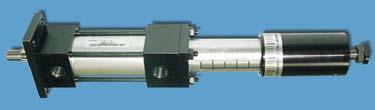
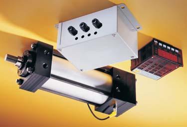
17 BACK-TO-BACK The Back-to-Back option consists of two separate cylinders assembled with common tie rods. For use when three or four rod positions are required, and a double rod style is acceptable. To order, specify each cylinder model, with Back-to-Back note. LINEAR TRANSDUCER READY Cylinder can be equipped ready to accept linear transducers (Bimba, Balluff, MTS, etc.), to provide actual position feedback throughout the entire stroke. To order, specify Ready for (type of transducer) at end of model number. (Note: TRD can furnish Bimba PFC transducers. Customer to provide and install all other types). CUSTOM SOLUTIONS SERIES SS : OPTIONS & CUSTOMS MULTIPLE POSITION The Multi-Position option is used when three, four or five rod positions are required in a single rod design. Piston rods are not connected. The back cylinder(s) achieve the mid-stroke positions. To order, specify model and each stroke position required. LAST POSITION (FULL STROKE) MID STROKE POSITION(S) POSITION (0 ) AIR/OIL TANDEM The Air/Oil Tandem cylinder consists of a hydraulic cylinder coupled with an air cylinder. Piston rods are connected. (Note: hydraulic unit is in front, having the exposed piston rod). Used to provide smooth, controlled stroke, even at slow speeds. To order, specify standard model number, with Air/Oil Tandem note. Still don t see what you need? No Problem With our extensive machining abilities, our engineering staff can assist with the design of a cylinder for your application. Call, fax or your specifications for a quick response When it comes to delivery, TRD has the reputation as being one of the fastest. No more long waits for your customized products Some examples of our abilities... Triple Piston Rod (Non-Rotating) Bore (Oversized Clevis) 0 Piston ( Wide Wear Bands) Bore with Bore Telescoping Hollow Rod Special MF Flange 7 Basic Cylinders Non-Rotating Cylinder Options Accessories Switches Air/Oil Tanks Multi-Stage Technical Data
18 Basic Cylinders Accessories Cross Reference Chart BORE SIZE ACCESSORIES: CLEVIS, PINS & MOUNTS CYLINDER MODEL STYLE (KK) THREAD CLEVIS EYE ACCESSORIES CLEVIS PIN CLEVIS BRACKET EYE BRACKET Non-Rotating Cylinder Options,,,, & # (STANDARD) # # (ST D-OVERSIZED) # # (STANDARD) # # (ST D-OVERSIZED) # # (STANDARD) # # (ST D-OVERSIZED) # CLEVIS PIN PART NO. CD LH LP SS-CP00 / KK KK KK KK KK KK KK KK KK KK KK KK 7/ SS-RC7 SS-RC00 SS-RC70 SS-RC000 SS-RC70 SS-RC000 SS-RC000 SS-RC0 SS-RC000 SS-RC0 SS-RC0 SS-RC00 SS-RE7 SS-RE00 SS-RE70 SS-RE000 SS-RE70 SS-RE000 SS-RE000 N/A SS-RE000 N/A N/A N/A SS-CP00 SS-CP00 SS-CP70 SS-CP000 SS-CP70 SS-CP000 SS-CP000 SS-CP7 SS-CP000 SS-CP7 SS-CP7 SS-CP70 SS-CB00 SS-CB70 SS-CB000 SS-EB00 SS-EB70 SS-EB000 Accessories (0 Stainless Steel) LH CLEVIS PIN HARD CHROME O.D. SS-CP70 / Accessories SS-CP000 SS-CP7 SS-CP70 Clevis Pins sold with () S.S. Cotter Pins 7/ LP CD +.000/-.00 Switches CLEVIS PART NO. CB CD CE CW ER KK L SS-RC7 SS-RC00 SS-RC70 SS-RC000 7/ / - L CW CB CLEVIS CW CD ER CE SS-RC0 / - / Air/Oil Tanks SS-RC00 Clevis Pins sold separately - EYE PART NO. A CA CB CD ER KK SS-RE7 SS-RE00 SS-RE70 / / 7/ 7/ CD CD KK EYE CD ER CD CB Technical Data Multi-Stage SS-RE000 SS-RE0 Clevis Pins sold separately CLEVIS BRACKETS EYE BRACKETS PART NO. SS-CB00 SS-CB70 SS-CB000 SS-EB00 SS-EB70 SS-EB000 Clevis Pins sold separately / 7/ / 9/ - - CLEVIS BRACKETS AND EYE BRACKETS BA CB CD CW DD E F FL L M - / 9/ - / / 9/ -0 N/A 7/ 7/ 7/ / F L M FL CD CA CLEVIS BRACKET DD TAP BA CW CB CW E A BA KK EYE BRACKET DD DIAMETER CB E
19 G B ALIGNMENT COUPLERS PART NO. A B C D E F G H SS-AC0 SS-AC SS-AC7 SS-AC7 SS-AC00 SS-AC SS-AC70 SS-AC7 SS-AC000 SS-AC0 SS-AC00 ACROSS () FLATS - /- - 7/ / / / / ACCESSORIES: ALIGNMENT COUPLERS Solid Stainless Steel self-aligning piston rod couplers TRD s alignment couplers can virtually pay for themselves by eliminating the need to precisely mount cylinders in your applications. Our couplers prevent binding and erractic movement that misalignment causes, extending the bearing and seal life of your cylinders. Proper use of alignment couplers will allow cylinders to stroke in the shortest time possible, increasing production Benefits Rod alignment couplers eliminate expensive machining for mounting fixed or rigid cylinders on guided or slide applications. Cylinder efficiency is increased by eliminating friction caused by misalignment. Couplers compensate for angular error and / lateral misalignment on push or pull strokes. Couplers provide greater reliability, performance, and reduce cylinder component wear. Simplifies alignment problems in the field. Design Tips Alignment couplers can be exposed to high stresses that are not apparent in an application. Always use the largest thread size practical in your application. (see chart for maximum pull yields) Use jam nut to lock coupler to rod when used with full diameter threads (example: thread on rod). Large thread sizes can be pinned in high impact applications, eliminating unwanted loosening of coupler from rod. Always use the smallest pin possible to avoid weakening the piston rod thread. (example: Use a / diameter pin for rod threads and larger) / / / / A THD. 7/ 7/ 7/ 7/ 7/ 7/ 7/ 7/ / / E F SHANK DIA. D / / / / / / / (REF. APPROX) / / C H ACROSS () FLATS / / / / / / / / 9 A TAP E DEEP MAX PULL AT YIELD,000 LBS.,00 LBS.,900 LBS.,000 LBS.,00 LBS. 7,000 LBS. 0,00 LBS.,000 LBS.,000 LBS. 7,000 LBS. 0,000 LBS. Spherical Movement / Axial Float SS-AC0 to SS-AC00 ± SPHERICAL MOVEMENT ±/ AXIAL FLOAT THREADS RANGE FROM - UNF to - UNF Basic Cylinders Non-Rotating Cylinder Options Accessories Switches Air/Oil Tanks Multi-Stage Technical Data
20 Technical Data Multi-Stage Air/Oil Tanks Switches Accessories Cylinder Options Non-Rotating Basic Cylinders Miniature AC/DC Reed High Power AC Reed Miniature DC Solid State Miniature AC/DC Reed with built-in Circuit Protection Extended Temperature Range Reed TRD offers Reed, High Power AC Reed, DC Solid State and Reed Switches with built-in Circuit Protection to meet a wide variety of customer needs. Advantages: Compact low profile Switch/Bracket Assembly Magnetically operated, can be located anywhere in the actuator stroke range Switches and Brackets are Nylon and Stainless Steel Hardware Can be used with all TRD Aluminum Series Actuators construction suitable for wash down or corrosive environments (TA, TD, TRA, FM, MSE, MSR), Electroless Nickel (IP7) Plated Series (EN), and Stainless Steel Series (SS) Quick, Simple Set-up: Requires Standard (slotted) Screw Driver (Note: Specify MPR option when ordering actuator) only Suitable for all bore sizes ( / to ) High visibility LED can be seen up to 0 feet One magnet (MPR) for all switch models Benefits of REED Switch R0 Miniature REED Switch -0 Volts AC, -0 Volts DC, 00 ma current rating (MAX.) Cable options include inch or 0 inch plain cable leads, and mm Threaded Quick Connect High visibility LED RAC High Power AC REED Switch Internal Circuit Protection Lower Cost Low or High Current Models available, AC or DC, and TRIAC type switch for inductive loads. High Visibility Red LED (on Low Current Models) Choice of lead lengths available on all models -0 Volts AC, 00 ma current rating, TRIAC output Cable options include inch or 0 inch plain cable leads MSS Miniature Solid State Switch Cable options include inch or 0 inch plain cable leads, and mm Threaded Quick Connect High Visibility LED R0P Miniature AC/DC REED Switch with builtin Circuit Protection -0 Volts AC, -0 DC, 0 ma current rating (MAX.) Cable options include inch or 0 inch plain cable leads High Visibility LED RHT Miniature Extended Temperature Range Reed Switch 0-0 Volts DC, -00 ma current rating -0 F to 0 F (-0 C to C) Can be wired Current Sinking (NPN) or Current Sourcing (PNP) Cable options include inch or 0 inch plain cable leads Switch Application Selection Guide For selecting the right switch for your application ACCESSORIES: SWITCHES Optional mm Quick Connect on Low Current Model SWITCH MODEL R0 or RHT REED SWITCH RAC HIGH POWERED REED SWITCH** MSS SOLID STATE SWITCH PROGRAMMABLE CONTROLLERS YES NO YES RELAYS <0VA* YES <00mA SOLENOIDS <0VA* YES No 0 Benefits of SOLID STATE Switch Shock Proof GMR Technology - Giant Magneto Restrictive Design Reverse Polarity and Over Voltage Protection High Visibility Red LED (All Models) Choice of lead lengths available or mm Quick Connect INDICATOR LIGHTS BULBS SOLID STATE <0VA* YES <00mA YES NO YES MOTORS <0VA* YES NO TIME COUNTERS <0VA* YES <00mA R0P REED SWITCH YES <0VA <0VA <0VA YES <0VA <0VA *Use resistor-capacitor protection **Minimum Current = 0mA
21 ACCESSORIES: SWITCHES REED Electrical Specifications R0 R0X Miniature Reed Switch, ( AWG Wire, PVC Jacket) Plain Cable Lead, ( wire Switch) Miniature Reed Switch, 0 ( AWG Wire, PVC Jacket) Plain Cable Lead, ( wire Switch) Contacts SPST Form A (Normally Open) Contact Rating 0 Watts Max. Input Voltage -0 Volts Max. AC, -0 Volts Max. DC Maximum Load Current 00 ma Max. C (77 F) 0 ma Max. 70 C ( F) Actuating Time Average.0 millisecond LED Indicator High Luminescence Housing Temperature Range -0 C to 70 C (- F to F) Protection Rating IP7 R0Q Miniature Reed Switch, mm Male Quick Connect, AWG Wire, PVC Jacket ( wire Switch) Contacts SPST Form A (Normally Open) Contact Rating 0 Watts Max. Input Voltage 0 Volts Max. AC or DC Maximum Load Current 00 ma Max. C (77 F) 0 ma Max. 70 C ( F) Actuating Time Average.0 millisecond LED Indicator High Luminescence Housing Temperature Range -0 C to 70 C (- F to F) Protection Rating IP7 R0P R0PX RAC RACX Miniature Reed Switch, ( AWG Wire, PVC Jacket) Plain Cable Lead, Circuit Protection ( wire Switch) Miniature Reed Switch, 0 ( AWG Wire, PVC Jacket) Plain Cable Lead, Circuit Protection ( wire Switch) Contacts SPST Form A (Normally Open) Contact Rating 0 Watts Max. Input Voltage -0 Volts Max. AC, 0 Volts Max. DC Maximum Load Current 0 ma Max. (Resistive) Actuating Time Average.0 millisecond LED Indicator High Luminescence Housing Temperature Range -0 C to 70 C (- F to F) Protection Rating IP7 Circuit Protection Varistor Volts Choke 0 µh High Power AC Reed Switch, (0 AWG Wire, PVC Jacket) Plain Cable Lead, ( wire Switch) High Power AC Reed Switch, 0 (0 AWG Wire, PVC Jacket) Plain Cable Lead, ( wire Switch) Contacts TRIAC Output Contact Rating 00 Watts Max. Input Voltage to 0 Volts (AC only) Minimum Load Current 0 ma Maximum Load Current 00 ma Actuating Time Average.0 milliseconds LED Indicator Not Available Temperature Range -0 C to 70 C (- F to F) Protection Rating IP7 Load Current De-Rating Graph R0 / R0X / R0Q (R0PX: 0 ma MAX., -0 C to 70 C) LOAD CURRENT (ma) Schematics R0 / R0X Miniature Reed Switch, Cable Type, ( Wire Switch) SWITCH BROWN BLUE LOAD + Input Voltage 0 Volts Max. DC, 0 Volts Max. AC Maximum Load Current 00 ma Max. C (77 F) 0 ma Max. 70 C ( F) R0Q Miniature Reed Switch, mm Male Quick Connect, ( Wire Switch) SWITCH (BROWN) POSITIVE (BLACK) NEGATIVE LOAD (BLUE) NOT CONNECTED Input Voltage 0 Volts Max. AC or DC Maximum Load Current 00 ma Max. C (77 F) 0 ma Max. 70 C ( F) RAC / RACX High Power AC Reed Switch, Cable Type, ( Wire Switch) SWITCH BROWN BLUE Contact Rating Input Voltage Minimum Load Current Maximum Load Current R0P / R0PX Miniature Reed Switch, Cable Type, Circuit Protected ( Wire Switch) Input Voltage Maximum Load Current Circuit Protection Varistor Volts Choke 0 µh Note: The circuit protection consists of a Varistor and Choke arrangement. The Varistor will take transient & voltage spikes out of the line and is mounted in parallel with the switch. The Choke will disperse inrush currents (normally caused by long cable runs) and is mounted in series with the switch. 0 SWITCH BROWN 0 BLUE AIR TEMPERATURE C F 0 Volts Max. AC, 0 Volts Max. DC 0 ma Max. (Resistive) LOAD + 00 Watts Max. to 0 Volts (AC only) 0 ma 00 ma LOAD + + [ ] OR [ ] + 00 ma C (77 F) 0 ma 70 C ( F) Basic Cylinders Non-Rotating Cylinder Options Accessories Switches Air/Oil Tanks Multi-Stage Technical Data
22 Switches Accessories Cylinder Options Non-Rotating Basic Cylinders ACCESSORIES: SWITCHES REED Electrical Specifications RHT / RHTX Miniature Reed Switch, Cable Type, Extended Temperature Range ( wire Switch) Contacts SPST Form A (Normally Open) Contact Rating 0 Watts Max. Input Voltage 0 Volts AC / 0 Volts DC Max. Maximum Current 00 ma Actuating Time Average.0 microsecond LED Indicator Not Available Temperature Range -0 C to C (-0 F to 0 F) Protection Rating IP7 Cable Silicone rubber insulation with white out sheath (.mm O.D.) Wires () AWG Note: The RHT has a cable length & the RHTX has a 0 cable length. MSS Miniature Solid State Switch, ( AWG Wire, PVC Jacket) Plain Cable Lead, ( wire Switch) MSSX Miniature Solid State Switch, 0 ( AWG Wire, PVC Jacket) Plain Cable Lead, ( wire Switch) *Output Type Current Sinking or Current Sourcing Input Voltage 0 to 0 Volts DC Current Consumption (not sensing) ma Minimum Load Current ma Maximum Load Current 00 ma ON Voltage Drop. ma. 00 ma LED Indicator High Luminescence Housing Temperature Range -0 C to 70 C (- F to F) Actuating Time Average.0 microseconds Protection Rating IP7 Reverse Polarity Protected yes Transient (over voltage) Protected yes SWITCHES SOLID STATE Schematics RHT / RHTX Miniature Reed Switch, Cable Type, Extended Temperature Range ( Wire Switch) SWITCH MSS / MSSX Miniature Solid State Switch, Cable Type, ( Wire Switch) SWITCH BROWN BLUE LOAD OR PLC INPUT Typical Current Sourcing (PNP) Configuration SWITCH BROWN BLUE BLACK BLUE LOAD* *The Load may be on the + or wire + LOAD OR PLC INPUT + Typical Current Sinking (NPN) Configuration + Air/Oil Tanks Multi-Stage Technical Data *NOTE: This is a () wire switch used in series with the load. Therefore, this switch can be used with devices requiring either a current sinking (NPN) output or a current sourcing (PNP) output from the solid state switch. MSSQ *Output Type Input Voltage Current Consumption (not sensing) Minimum Load Current Maximum Load Current ON Voltage Drop LED Indicator Temperature Range Actuating Time Average Protection Rating Reverse Polarity Protected Transient (over voltage) Protected Miniature Solid State Switch, mm Male Quick Connect, AWG Wire, PVC Jacket ( wire Switch) Current Sinking or Current Sourcing 0 to 0 Volts DC ma ma 00 ma ma 00 ma High Luminescence Housing -0 C to 70 C (- F to F).0 microseconds IP7 yes yes MSSQ Miniature Solid State Switch, mm Male Quick Connect, ( Wire Switch) SWITCH (BROWN) POSITIVE (BLACK) NEGATIVE LOAD OR PLC INPUT Typical Current Sourcing (PNP) Configuration SWITCH *NOTE: This is a () wire switch used in series with the load. Therefore, this switch can be used with devices requiring either a current sinking (NPN) output or a current sourcing (PNP) output from the solid state switch. (BLUE) NOT CONNECTED (BROWN) POSITIVE (BLACK) NEGATIVE (BLUE) NOT CONNECTED Typical Current Sinking (NPN) Configuration + LOAD OR PLC INPUT +
23 ACCESSORIES: SWITCHES AND BRACKET DIMENSIONS FOR SWITCHES: R0 / R0X RHT / RHTX MSS / MSSX PLAIN CABLE LEADS R0 / RHT / MSS = (0.m) PVC JACKETED LEADS R0X / RHTX / MSSX = 0 (.0m) (JACKET CUT BACK ON END) (.) FOR SWITCHES: R0Q MSSQ RUGGED THREADED CONNECTION FOR POSITIVE LOCK FOR SWITCHES: RAC / RACX R0P / R0PX SWITCH BRACKET: SB (For Through Bore Cylinders) SWITCH BRACKET: SB (For Through Bore Cylinders) QUICK CONNECT CORD SETS (Used with Q Type Switch Leads) PLAIN CABLE LEADS R0P / RAC = (0.m) JACKETED LEADS R0PX / RACX = 0 (.0m) (JACKET CUT BACK ON END) (.) Bracket Construction: Molded Nylon (Black) and Stainless Steel Hardware Bracket Construction: Molded Nylon (Black) and Stainless Steel Hardware FOR CABLES: C-T ( METER CABLE LENGTH) CX-T ( METER CABLE LENGTH) All Dimensions are in INCHES (mm in parentheses) mm UNIVERSAL () PIN MALE CONNECTOR (Q-OPTION) M x THD. CONDUCTOR COLORS:. BROWN. BLUE. BLACK.0 (.) TIE MTG. HOLE COUPLING NUT.0 (.).9 (9.9).0 (.). (.0) SWITCH MTG. HOLE CLAMP TIGHTENING SCREW. (.7) M X THD. (FEMALE). () HOUSING CONSTRUCTION - MOLDED NYLON (WHITE) HOUSING CONSTRUCTION - MOLDED NYLON (WHITE) CLAMP TIGHTENING SCREW SWITCH MTG. HOLE C-T = 7.7 ( METERS) CX-T = 9. ( METERS).9 (9.9) HOUSING CONSTRUCTION - MOLDED NYLON (WHITE).9 (9.9). (.7) TIE MTG. GAP JACKETED CABLE-ENDS STRIPPED & TINNED Basic Cylinders Non-Rotating Cylinder Options Accessories Switches Air/Oil Tanks Multi-Stage Technical Data
24 Basic Cylinders Non-Rotating Cylinder Options C (REF) ACCESSORIES: SWITCH MOUNTING DIMENSIONS SB A (REF) A (REF) B (REF) ØD (REF) ØD (REF) G G SB E E PART NO. SB SB SWITCH BRACKET LETTER DIMENSIONS BORE 0 A 7/ / 7/ 7/ * * /* * B C D E G / / 7/ / * * * /* * 0 / / / / / 9/ 9/ 9/ 9/ 9/ 9/ 9/ *THESE DIMENSIONS ARE OF THE C DIMENSION. THE SWITCH BRACKET DOES NOT PROTRUDE BEYOND STANDARD HEAD/CAP. Accessories C (REF) B (REF) SB SB Switches Air/Oil Tanks How To Assemble Switch and Brackets Recommended Torque: -0 Inch-Lbs. (Do Not Exceed Inch-Lbs.) Recommended Torque: - Inch-Lbs. (Do Not Exceed Inch-Lbs.) Multi-Stage Technical Data SB SWITCH BRACKET (MOUNTING ILLUSTRATION) SB SWITCH BRACKET (MOUNTING ILLUSTRATION)
25 HYSTERESIS: ACCESSORIES: SWITCH HYSTERESIS & BAND WIDTH THE DISTANCE BETWEEN THE SWITCH BREAK POINT MOVING IN ONE DIRECTION, AND THE SWITCH MAKE POINT MOVING IN THE OPPOSITE DIRECTION. BAND WIDTH: THE DISTANCE THE PISTON MOVES WHILE THE SWITCH IS MADE (IN EITHER DIRECTION), LESS THE HYSTERESIS. SWITCH MAKE POINT DIRECTION OF PISTON MOTION HYSTERESIS.0 () SWITCH BREAK POINT MSS.0 (0) R0 CENTER OF SENSING ZONE SWITCH ON SWITCH ON BAND WIDTH. (.) RAC CENTER OF SENSING ZONE CENTER OF SENSING ZONE SWITCH BREAK POINT SWITCH MAKE POINT DIRECTION OF PISTON MOTION MID STROKE OPERATION.0 (0) R0P CENTER OF SENSING ZONE HYSTERESIS R0 R0X R0Q Switch Switch R0P R0PX Switch RAC RACX Switch MSS MSSX MSSQ Note: Dimensions are in inches, (mm in parentheses). Results are based upon TRD piston and magnet assemblies. Results may vary if used with other manufacturers cylinder products. RHT RHTX Repeatability ±.00 (±.) Repeatability ±.00 (±.) Repeatability ±.00 (±.) Repeatability ±.00 (±.) SWITCH MAKE POINT DIRECTION OF PISTON MOTION SWITCH BREAK POINT Hysteresis (Maximum).00 () Hysteresis (Maximum).0 (.) Hysteresis (Maximum).07 (.9) SWITCH ON SWITCH ON SWITCH BREAK POINT SWITCH MAKE POINT DIRECTION OF PISTON MOTION TERMINOLOGY ILLUSTRATION SWITCH MAKE POINT DIRECTION OF PISTON MOTION HYSTERESIS SWITCH BREAK POINT SWITCH ON SWITCH ON BAND WIDTH END OF STROKE OPERATION Hysteresis (Maximum).00 () Band Width (Minimum).00 () Band Width (Minimum). (.) Band Width (Minimum). () END OF STROKE Band Width (Minimum).00 () Basic Cylinders Non-Rotating Cylinder Options Accessories Switches Air/Oil Tanks Multi-Stage Technical Data
26 Technical Data Multi-Stage Air/Oil Tanks Switches Accessories Cylinder Options Non-Rotating Basic Cylinders ACCESSORIES: SWITCH ORDERING INSTRUCTIONS TO ORDER, SPECIFY: Switch Model, Lead Type, and Bracket Size R0 X - SB Switch Model Switch Lead Options Switch Bracket R0 = AC/DC Reed RAC = High Power AC Reed RHT = Extended Temperature Reed MSS = Solid State R0P = AC/DC Reed with Circuit Protection MODEL C-T CX-T About our switches (leave blank) = Plain Cable X = 0 Plain Cable Q = mm Quick Connect (not available on RAC, RHT) Switch Accessories Quick Connect Cord Sets Application recommendations and precautions SB = to Bore SB = to Bore (leave blank for switch only) DESCRIPTION mm Straight Quick Connect Cord X Meter (7 ) mm Straight Quick Connect Cord X Meter (9 ) Our switches are different The most common complaint in the market is the unreliability of magnetically operated switches. Most cylinder piston magnets have about 0-0% more power than required to operate the switch. This results in erractic operation, a nuisance for maintenance and lowering overall plant productivity. TRD designed our magnet to have 0-00% more power than required to operate our switch The combination of TRD R0, R0P, RAC, RHT and MSS Switches and our Cylinders, raises the reliability of switch operation comparable to that of many mechanically operated limit switches. Noise suppression - Motors and valve solenoids will produce high pulses throughout an electrical system. Therefore, primary and control circuit wiring should not be mixed in the same conduit. Separate power supplies for both logic level signals (Microprocessor, P.C., CPU, Input Devices) and Output Field Devices (Motors, Valve Solenoids) is recommended. Never connect R0, R0P, RHT or MSS type switches without a load present. The switch will be destroyed. Some electrical loads may be capacitive. Capacitive loading may occur due to distributed capacity in cable runs over feet. Use switch model RAC whenever capacitive loading may occur. To obtain optimum performance and long life, switches should not be subjected to strong magnetic fields, extreme temperatures (outside of specifications), or excessive ferrous filings or chip buildup. Improper wiring may damage or destroy the switch. Therefore, the wiring diagrams along with the listed power ratings, should be carefully observed before connecting power to the switch. Following these tips can save time and provide trouble free installations Other switches available: mm Quick Connect Pulse Extension Switch (For Sensing Mid-Stroke Positions) Special Length Cable Change Over Switch (SPDT) Weld Immune Switch (Consult factory for details.)
27 Series SS-AT features: 0/0 Stainless Steel Hardware 00 PSI Operating Pressure Internal Steel baffles to reduce aeration and foaming Fiber wound translucent tube (non-fda material) Optional stainless steel tube, fittings and sight glass (FDA approved materials) Standard mount (MS), ( tapped mounting holes back side) Side lug mount (MS) optional Fill port located in top, drain port in bottom cap Optional oversized ports for high flow applications (For oil velocity exceeding feet per second) EE AIR FLOW PATH SS-AT MODEL PART NO. BORE SS-AT0 SS-AT SS-AT00 SS-AT00 SS-AT00 PLUS INTERNAL LENGTH * This is total internal volume, not recommended usable oil capacity. ** Fill and drain ports located at top & bottom of air oil tank. TABLE B CYLINDER PISTON AREA CYLINDER BORE (In.) F TYP. EE OIL FLOW PATH BACK VIEW **DRAIN PORT SERIES SS-AT : AIR/OIL TANKS TANK DIMENSIONS *GALS PER INCH TANK A B C D F G EE PISTON AREA (Sq. In.) C D EE FILL PORT** B () G TAPPED HOLES (FOR MOUNTING) BORE AREA A INTERNAL LENGTH / / 7/ 9/ 9/ / / - x DEEP - x DEEP - x DEEP - x DEEP -0 x / DEEP TABLE C RECOMMENDED USABLE TANK VOLUME (cubic inches) WITH 0% SAFETY FACTOR MAXIMUM FLUID LEVEL MINIMUM FLUID LEVEL 0 () EE N.P.T FRONT VIEW ACTUAL INTERNAL LENGTH OF TANK The TRD air/oil system gives you the smooth operation typically associated with hydraulic systems, without the expense Uses shop air, () air/oil tanks, and a cylinder equipped with TH (hydraulic seals). Low initial investment and low maintenance to operate Tanks need to be mounted above the cylinder, but not necessarily by the cylinder. This will create a self-purging oil circuit. It is advisable to size tanks 0-0% larger than cylinder volume, to prevent the tanks from running dry and to allow for heat expansion. Sizing your air/oil tank:. Determine the cylinder volume by multiplying the square inches of piston area by the inches of stroke. (See Table B) Add 0-0% to determine actual tank size.. Find the volume closest to your tank volume requirement in Table C. (Note: Tanks of smaller diameters with greater lengths are generally less expensive than larger diameter, short tanks of equal volume).. To order, specify Bore and internal length required. Example: SS-AT0 x ( Bore, internal tank length, with a usable volume of cubic inches) EE AIR SUPPLY TYPICAL AIR-OIL CIRCUIT AIR OIL FLOW CONTROL (OUT STROKE) AIR CONTROL VALVE AIR OIL FLOW CONTROL (RETURN STROKE) Basic Cylinders Non-Rotating Cylinder Options Accessories Switches Air/Oil Tanks Multi-Stage Technical Data


28 Accessories Cylinder Options Non-Rotating Basic Cylinders FORCE MULTIPLYING CYLINDERS Optional force multiplying in both extend and retract strokes available How they work SERIES SS-MS : MULTI-STAGE Benefits The TRD SS-MSE and SS-MSR Series are double acting, single rod end cylinders that multiply the force output by supplying air to multiple pistons. The SS-MSE multiplies the force on the extend stroke, the SS-MSR multiplies the force on the retract stroke. Both models use only one piston on the return stroke, saving air volume and operating costs. Rated for PSI Air, or Hydraulic (non-shock) Eliminates the need for high pressure systems Bore size vs. output force saves space Optional Double Rod End Models available Heavy Duty S.S. construction Stage, Stage and Stage models Switches Model SS-MSE Extension-air supplied to multiple pistons Stage Shown INLET EXHAUST EXHAUST EXHAUST EXHAUST EXTENDING Force multiplying in both Extend and Retract strokes (Note: Overall lengths are increasedconsult factory for details) To Order, specify: SS-MSE/MSR as model number. Air/Oil Tanks Retraction-air supplied to one piston EXHAUST AIR DRAWN IN RETRACTING INLET Extension AND Retraction-air supplied to multiple pistons INLET EXTENDING STROKE INLET Multi-Stage Model SS-MSR Retraction-air supplied to multiple pistons Stage Shown EXHAUST EXHAUST EXHAUST EXHAUST INLET RETRACTING EXHAUST EXHAUST RETRACTING STROKE EXHAUST EXHAUST Technical Data Extension-air supplied to one piston INLET AIR DRAWN IN EXTENDING EXHAUST INLET Model SS-MSE/MSR Stage Shown INLET
29 SERIES SS-MS : ORDERING INSTRUCTIONS Stainless Steel Multi-Stage NFPA Mount Cylinders Force Multiplier Air and Non-Shock Hydraulic Cylinders PSI Six Bore Sizes thru Bores, Extend or Retract, or Stages BASIC MODEL SS-MSE SS-MSR MULTI STAGE EXTEND MULTI STAGE RETRACT D ORDERING EXAMPLES: MODEL VARIATIONS LEAVE BLANK IF NONE DOUBLE END EXAMPLE : MF Bore, Stroke, Stage Force Multiplied in EXTEND is: SS-MSE MF x x S EXAMPLE : Double Rod End MS Mount, Stage, Bore, Stroke, Force Multiplied in RETRACT with Magnetic Piston for REED Switches is: SS-MSR MSD x x S - MPR (NOTE: MPR Option adds to Cylinder Length) NFPA MOUNTS MX0 MX MF MP MS MX MX MF MP MS BORE X STROKE X STAGES TO CONSULT FACTORY FOR OTHER STROKES OPTIONS SS-MS SERIES CYLINDERS - STAGE EXTEND OR RETRACT STANDARD DIAMETER BASIC DIMENSIONS MXO EE NPT () R E SQ. B DIA. KK THDS. MM DIA. A C V F BORE A B C E EE F G J K KK LE MM PE R V Y ZE Y / 7/ 7/-0. 7/ 7/ / 9/ 7/-0. 7/ 9/ / 9/ 7/-0.9 7/ 9/ / - 7/.7 7/ / - 7/. 7/ / / - 7/.0 7 / / -. / G S S S TWO THREE FOUR OPTION LENGTH ADDER (ADD TO CATALOG BASIC OVERALL LENGTH DIMENSIONS) BORE OPTION B BC BH MPR MPH NR 7/ 7/ 7/ MPR/MPH OPTION: Magnet is located in stage at cap for standard units, in stage at head for NR units. STAGE ADDS LENGTH TO CYLINDER - SEE CHART X B / URETHANE BUMPER BOTH ENDS X BH / URETHANE BUMPER HEAD ONLY X BC / URETHANE BUMPER CAP ONLY A - EXTEND PISTON THREAD (SPECIFY) C - EXTEND PISTON (SPECIFY) H HEAD CUSHION (AVAILABLE ON MSE ONLY) C CAP CUSHION (AVAILABLE ON MSR ONLY) DRB DELRIN BUSHING FDAL FDA APPROVED LUBRICANT KK LARGE MALE THREAD KK FEMALE THREAD KKS STUDDED PISTON (WITH KK) KK FULL DIAMETER MALE THREAD X MPR MAGNETIC PISTON FOR REED SWITCHES X MPH MAGNETIC PISTON FOR HALL SWITCHES X MS NR METALLIC SCRAPER (BRASS) NON-ROTATING (INTERNALLY GUIDED) ADDITIONAL LENGTH - SEE CHART BELOW OP OS ST TH VS AS XX PE + X STROKE LE + X STROKE ZE + X STROKE STAGE OPTIONAL PORT LOCATION OVERSIZED DIAMETER (SPECIFY SIZE) STOP TUBE (SPECIFY LENGTH) HYDRAULIC (NON-SHOCK) FLUOROCARBON SEALS ADJUSTABLE STROKE (RETRACT) SPECIAL VARIATION (SPECIFY) BSP, SAE PORTS (SPECIFY SIZE) J K Basic Cylinders Non-Rotating Cylinder Options Accessories Switches Air/Oil Tanks Multi-Stage Technical Data 9
30 Basic Cylinders SS-MS SERIES CYLINDERS - STAGE EXTEND OR RETRACT STANDARD DIAMETER BASIC DIMENSIONS MXO EE NPT () B DIA. Y PG + X STROKE MM DIA. KK THDS. Non-Rotating Cylinder Options Accessories R E SQ. A C V BORE A B C E EE F G J K KK LG MM PG R V Y ZG / 7/ 7/-0. 7/ 7/ / 9/ 7/-0. 7/ 9/ / 9/ 7/-0.9 7/ 9/ / - /.7 / F / - /. / / / - /.0 / / / G STAGE STAGE LG + X STROKE ZG + X STROKE STAGE J K Switches SS-MS SERIES CYLINDERS - STAGE EXTEND OR RETRACT STANDARD DIAMETER BASIC DIMENSIONS MXO EE NPT () B DIA. Y PH + X STROKE MM DIA. KK THDS. Air/Oil Tanks A STAGE STAGE STAGE STAGE R C V F G LH + X STROKE ZH + X STROKE J K Multi-Stage Technical Data E SQ. BORE A B C E EE F G J K KK LH MM PH R V Y ZH / 7/ 7/-0. 7/ 7 7/ / 9/ 7/-0. 7/ 7 9/ / 9/ 7/-0.9 7/ 7 9/ / - 7 7/.7 9 / - 7 7/. 9 / / - 7 7/.0 9 9/ / - 7. / 0
31 BORE SERIES SS-MS DIMENSIONS: OVERSIZED A / / / B Oversize Rod Diameter Basic Dimensions MXO (No Mount) B DIA. B DIA. B DIA. For dimensions not shown see pages 9 & 0 MULTI-STAGE OVERSIZE DIAMETER C KK THDS. KK THDS. KK THDS. MM DIA. F MM DIA. MM DIA. A A C A V C V F V C F V F KK STAGE - STAGE ZE + X STROKE STAGE ZG + X STROKE STAGE MM STAGE ZH + X STROKE STAGE STAGE STAGE ZE / / / 7 / 7 / 7 / 7/ STAGE ADD STROKE PER STAGE ZG / / / 9/ 9 / ZH 7 / 7 / 7 / / 7/ Basic Cylinders Non-Rotating Cylinder Options Accessories Switches Air/Oil Tanks Multi-Stage Technical Data
 threads, Metric threads or just plain rod ends are common.")

32 SERIES SS DIMENSIONS: SS-MS DIMENSIONS About Rod End Styles Style Male Rod End is STANDARD Other NFPA Styles can be specified (See Chart). Need a rod end not listed? NO PROBLEM Each Piston Rod is made to order and does not delay shipment. Coarse (UNC) threads, Metric threads or just plain rod ends are common. Thread lengths are also made to order (Specify: A =Length). NEED SOMETHING NOT LISTED? Just send us a sketch. Quotes are turned around in one day PISTON END STYLES STYLE & STYLE STYLE EASY FLIP OUT PAGE FOR REFERENCE BORE,,,, & MM DIAMETER Standard Oversize Standard Oversize Standard Oversize STANDARD Style - Male KK A 7/-0 - / - / Style - Male KK A -0 7/- / 7/- / OPTIONAL Style - Female KK A 7/-0 - / - / Style - Male KK A - - / - / C V DD DD AA MX AA R BB FH BB R DD DD MX AA AA MX BB R R BB FH TIE EXTENDED MX, MX & MX MOUNT DIMENSIONS BORE DIAMETER Standard Oversize Standard Oversize Standard Oversize Standard Oversize AA BB / / DD - /- /- - FH R TIE EXTENDED MX, MX & MX MOUNT DIMENSIONS BORE DIAMETER AA BB DD FH R Standard Oversize Standard Oversize Standard Oversize.7..9 / /
33 EASY FLIP OUT PAGE FOR REFERENCE SERIES SS DIMENSIONS: SS-MS DIMENSIONS About Rod End Styles Style Male Rod End is STANDARD Other NFPA Styles can be specified (See Chart). Need a rod end not listed? NO PROBLEM Each Piston Rod is made to order and does not delay shipment. Coarse (UNC) threads, Metric threads or just plain rod ends are common. Thread lengths are also made to order (Specify: A =Length). NEED SOMETHING NOT LISTED? Just send us a sketch. In most cases, quotes are turned around in one day BORE,,,, & BORE DIAMETER Standard Oversize Standard Oversize Standard Oversize Standard Oversize Standard Oversize Standard Oversize Standard Oversize MM DIAMETER Standard Oversize Standard Oversize Standard Oversize STANDARD Style - Male KK A 7/-0 - / - / STYLE & STYLE STYLE Style - Male KK A -0 7/- / 7/- / MF, MF FLANGE DIMENSIONS PISTON END STYLES OPTIONAL Style - Female KK A 7/-0 - / - / E FB FH R TF UF W /.. /.9 7/ 7/.7 / 7/. 7/ 9/.0 7 9/. 7 7/ / Style - Male KK A - - / - / SERIES SS-MS DIMENSIONS: FLANGE MOUNTS TF UF FB HOLES () R E W FH - BORES MF W FH MF ZF + STROKE FH - BORES C FB HOLES () TF UF V R E ZF + STROKE PER STAGE STAGE STAGE STAGE 7/ / / 7/ 7 / 7/ 7 / / / Basic Cylinders Non-Rotating Cylinder Options Accessories Switches Air/Oil Tanks Multi-Stage Technical Data
34 Basic Cylinders SERIES SS-MS DIMENSIONS: PIVOT MOUNTS CD DIA. (PIN INCLUDED) CD DIA. (PIN INCLUDED) MP MP Non-Rotating Cylinder Options Accessories BORE XC + STROKE MULTI-STAGE MP & MP CLEVIS AND MP EYE MOUNT DIMENSIONS DIAMETER CB CD CW FL L Standard Oversize / Standard Oversize / Standard Oversize / Standard Oversize 7/ Standard Oversize 7/ Standard Oversize 7/ Standard Oversize For dimensions not shown see pages 9-0 * (Pivot Pin included) L M CW CW CB M 7/ 7/ 7/ XD + STROKE FL M CB STAGE ADD STROKE PER STAGE STAGE STAGE XC XD XC XD XC XD / 7 / 7 / / 7 / 7 / / 7 / 7 / / 7 / 7 / / 7 / 7 / / 7 / 7 / 7 / / 7 / / 7 / / 7/ 9 0 / 7/ 9 / 9 7/ 0 / 7/ Switches SS-MS SERIES: BASE MOUNTS Air/Oil Tanks E/ TN () NT TAP, TK DEEP XT MS SN + STROKE (PER STAGE) Multi-Stage Technical Data BORE DIAMETER Standard Oversize Standard Oversize Standard Oversize Standard Oversize Standard Oversize Standard Oversize Standard Oversize E/ 7/ For dimensions not shown see pages 9-0 MS BOTTOM TAPPED MOUNT DIMENSIONS NT TK TN XT STAGE -0 / / /- 7/ / / - / / - 7/ / - / 7/ / - / 7/ / -0 / / / 7/ SN + STROKE PER STAGE STAGE STAGE 7/
35 BORE SERIES SS-MS DIMENSIONS: BASE MOUNTS () SB DIA. HOLES DIAMETER Standard Oversize Standard Oversize Standard Oversize Standard Oversize Standard Oversize E/ SB 7/ 7/ 7/ 9/ 9/ * SS dimensions increase on double rod cylinders For dimensions not shown see pages 9-0 ST Note: overall lengths will change with the addition of non-rotating or magnetic pistons consult factory BORE 7/ TS US EE NPT () ST MS SIDE LUG MOUNT DIMENSIONS SU / / / E/ SW SZ SW XS TS SU SS + STROKE (EACH STAGE) US SZ SW SS + STROKE PER STAGE XS STAGE STAGE STAGE 7/ / 7/ / 7/ / 7/ / SS-MS SERIES EFFECTIVE PISTON AREA/FORCE CHART STAGES MS EFF. PISTON AREA (SQ. IN.) FORCE IN LBS. AT 0 PSI FORCE IN LBS. AT 00 PSI EXTEND (MSE) RETRACT (MSR) EXTEND (MSE) RETRACT (MSR) EXTEND (MSE) RETRACT (MSR) STD. ø O SIZE ø STD. ø O SIZE ø STD. ø O SIZE ø STD. ø O SIZE ø STD. ø O SIZE ø STD. ø O SIZE ø Basic Cylinders Non-Rotating Cylinder Options Accessories Switches Air/Oil Tanks Multi-Stage Technical Data
 is the load to be moved?")
36 Switches Accessories Cylinder Options Non-Rotating Basic Cylinders How to determine the right size Cylinder for the job SERIES SS : TECHNICAL DATA To determine what size cylinder the task requires, you need to answer a few questions about three main points: load, velocity and air pressure. How heavy (in pounds) is the load to be moved? The answer to this is usually given, set by the machine design. However, unless you are lifting a load vertically-with no external friction, it can be difficult to determine the true load. If the load cannot be calculated, try to physically measure the load. The closer the true load is known, the better the results. In order to move the load, you need to choose a cylinder that provides force greater than the load. So, if the load is 00 lbs., it will take of force greater than 00 lbs. to move it. In fact, it s a good idea to allow an additional factor of % force to allow for friction. What s the required velocity? Although velocity may also be set by machine design, often you have some latitude within a range. Whenever possible, for best results, we recommend using moderate speed because the greater the velocity required, the greater the additional force needed to achieve it. Slow speeds (up to in/sec) require % more force than the load, moderate speeds ( to in/sec) about 0% more, and high speeds (greater than in/sec) about 00% more force. So, for that 00 lb. load, you need lbs. of force to move it slowly, 0 lbs. of force to move it at moderate speeds, and 00 lbs. of force to move it quickly. Don t forget to add lbs. (% of 00 lbs.) for friction What s the minimum effective air pressure you can use - and is your pressure source constant? This is important because high pressures can accelerate seal wear and create stress on the cylinder, and inconsistent pressures can cause system malfunctions or failures. So, to maximize cylinder life and performance, you need to provide consistent airflow at the minimum effective pressure to maintain the desired velocity. The idea then, is for the cylinder to be able to move the maximum load, at the minimum acceptable velocity, and at the minimum available pressure. About bore sizes Once you ve determined the force you need to move the load at the desired velocity and allow for friction, here s how to find the cylinder bore that meets your specifications. The force generated by a cylinder is determined by the effective piston area times the air pressure. The chart below lists the effective piston area for each bore size, the Push (extend) and Pull (retract) stroke, at various air pressures. If you assume a maximum load of 00 lbs., a minimum velocity of in/sec, and a minimum pressure of 0 psi, here s how to select the right cylinder bore. Since the velocity is slow, the force should be % greater than the load, or lbs. After adding lbs. for friction (% of 00 lbs.), the total force needed is 0 lbs. The chart below shows that at 0 psi, the bore with rod extend force is lbs., and retract force is 70 lbs. - the right cylinder for the application. FORCE/VOLUME CHART Air/Oil Tanks Multi-Stage Technical Data CYLINDER BORE ALL ALL ALL ALL ALL ALL ALL ALL STROKE TYPE PUSH PULL PULL PUSH PULL PULL PUSH PULL PULL PUSH PULL PULL PUSH PULL PULL PUSH PULL PULL PUSH PULL PULL PUSH PULL PULL EFFECTIVE PISTON AREA POUNDS OF FORCE AT PSI CU. FT. DISPLACEMENT PER IN. OF STROKE


37 SERIES SS : TECHNICAL DATA How the right mounting and careful installation help prevent premature cylinder wear Choosing the right style of mounting for your cylinder s size, force and function has a direct effect on it s service life. The wrong mounting, or incorrect installation, can result in side load, which creates excessive wear on the piston, piston rod, rod bearing and seals. When wear occurs, leakage usually follows and that s how cylinders fail. Side load occurs when a load is placed on the piston rod without guideance or support, or when the mounting and piston rod connection are misaligned. It can also occur in pivot type mounts when the weight of the cylinder places load on the piston and rod bearing points. There are cylinder mounts and options to suit virtually every application. Pivot Type Mountings: Clevis & Trunnion Choose options that enhance and extend the working life of your cylinders 7 Rigid Mount Cylinders These type of mounts can eliminate side load in one Base mounted, flange mounted, and tie-rod mounted plane, but careful alignment in the other plane is crucial. cylinders must be carefully aligned with the direction of Since TRD uses a floating Rod Bushing design, side load travel to avoid side loads. loading caused by misalignment is minimized, but not If for some reason, proper alignment cannot be totally eliminated. maintained throughout the entire cylinder stroke, a rod end connection that allows for some lateral misalignment Long stroke pivot mount cylinders will have high side should be used. TRD offers a full line of Rod Alignment loads just because of the weight of the cylinder Couplers to solve misalignment issues (refer to page 9 components. In these applications, a stop tube is usually for details). Keep in mind, the rod alignment couplers do essential for proper cylinder operation (see page to not provide any rod end support. Always check to see if determine if a stop tube is needed for your application). your application requires a stop tube. MP - Bores Page MP - Bores Page MT - Bores Page MT - Bores Page Cushions. Can be designed into either one or both ends of the cylinder to provide controlled deceleration. This option prevents excessive end-of-stroke impact, reducing vibration and noise. Cushions are designed to stop light loads at moderate speeds. Heavy loads or higher speed applications may require shock absorbers. Your local distributor representative is qualified to provide expert advise on what options are best suited for your application. Bumper Piston Seals. Whether used by themselves or with cushions, bumper piston seals provide additional controlled deceleration at end of stroke. Wear band. A / thick X wide (for to bore, larger strips for bigger bores) PTFE composite material strip is added to the piston diameter to eliminate metal to metal contact between the piston and the tube. Since wear band materials are compressive in nature, they can provide some cylinder side load protection. As side load pressure is applied, the wear band contact area with the tube increases, enabling a higher transfer of load due to the high amount of contact area. Even though wear bands contain a high percentage of PTFE, they do add additional internal drag in the cylinder. Additional drag can effect cycle rates, and at times, lower overall production in high speed applications. MX, MX, MX - Bores Page 7 MF & MF - Bores Page 7 ME & ME Bore Page 7 MS & MS - Bores Page Fluorocarbon Seals. Usually associated with higher temperature applications, Fluorocarbon can provide additional chemical resistance. Consult factory for additional information. Stainless Steel Piston (with wear band). When cylinder bores are used to measure or dispense food products, it is essential to eliminate non-fda approved materials from the cylinder internal construction. Specify FDA approved materials only, at time of order. FDA Lubricant. Typically used with stainless steel pistons for food dispensing applications. Can also be specified when there is concern for possible contamination from petroleum based, air-born particles associated with the normal cylinder operation. Switches. Position sensing switches give you the potential for expanding the capabilities of your cylinder functions to include accurate piston sensing, event timing, sequencing and more. Magnetically operated, the switches are mounted to the exterior of the cylinder where they are actuated by a magnet contained on the piston. Refer to pages 0- for more details. Basic Cylinders Non-Rotating Cylinder Options Accessories Switches Air/Oil Tanks Multi-Stage Technical Data
38 Switches Accessories Cylinder Options Non-Rotating Basic Cylinders BORE * Weight includes clevis pins. PART NO. SS-RC7 SS-RC00 SS-RC70 SS-RC000 SS-RC0 SS-RC00 DIAMETER SERIES SS : TECHNICAL DATA Weight Chart - Basic Cylinders MX0/MS ME/ME WEIGHT IN POUNDS MODEL MF/MF N/A N/A MT/MT MP* ADD PER INCH OF STROKE Accessories Weight Chart WEIGHT IN POUNDS CLEVIS EYES EYE BRACKETS & CLEVIS BRACKETS CLEVIS PINS WEIGHT PART NO. SS-RE70 SS-RE000 SS-RE7 SS-RE00 WEIGHT PART NO. SS-EB00 SS-EB70 SS-EB000 SS-CB00 SS-CB70 SS-CB000 WEIGHT PART NO. SS-CP00- SS-CP70- SS-CP000- SS-CP7- SS-CP WEIGHT Air/Oil Tanks Alignment Couplers Weight Chart PART NO. SS-AC0 SS-AC SS-AC7 SS-AC7 SS-AC00 SS-AC.0 WEIGHT IN POUNDS WEIGHT PART NO..0 SS-AC70. SS-AC7. SS-AC000. SS-AC0. SS-AC00 WEIGHT Multi-Stage Technical Data Cylinder Torques CYLINDER BORE TIE THREAD SIZE TORQUE IN FT.-LBS. - /- / Tighten cylinders using an X tightening pattern on tie rods. Break-away Pressures SS SERIES CYLINDER BORE STANDARD SEALS LOW FRICTION (LF) - PSI - PSI - PSI - PSI - PSI - PSI - PSI - PSI - PSI - PSI - PSI - PSI - PSI - PSI - PSI - PSI

39

40
FULL COLOR TAB #1 TA 7
 FULL COLOR TAB #1 TA 7 TA - How to Order Floating Rod Bushing SELF ALIGNMENT FEATURE Rod Bushing is designed to float.00 to improve bearing surface alignment. SERIES TA (NFPA) CYLINDER Reduces cylinder
CYLINDERS OPTIONS ACCESSORIES
 CYLINDERS NFPA Interchangeable 1.50 thru 1 Bores 50 PSI Pneumatic Strokes to 10 Inches Permanent Lubrication Temperatures: 00 F Standard Double Acting Multi-Stage Multi-Position Triple Rod Flush Mount
SERIES TA (NFPA) CYLINDER
 CYLINDER") Floating Rod Bushing SELF ALIGNMENT FEATURE Rod Bushing is designed to float.00, improving bearing surface alignment. SERIES (NFPA) CYLINDER Reduces cylinder drag and erractic operation Reduces cylinder
Floating Rod Bushing SELF ALIGNMENT FEATURE Rod Bushing is designed to float.00, improving bearing surface alignment. SERIES (NFPA) CYLINDER Reduces cylinder drag and erractic operation Reduces cylinder
Air/Oil Tanks Air Boosters Cylinder Options Multi-Stage Triple-Rod Basic Cylinders Accessories Technical Data TRA HOW TO ORDER: SERIES TRA (TRIPLE PIS
 SERIES TRA TRIPLE ROD NEW HEAVY-DUTY TRIPLE ROD DESIGN TRD s TR Series has been redesigned. The new series, TRA is a Heavy-Duty version of the TR Series. The new series is a drop-in replacement of the
Heavy Duty Bench Top Presses
 Heavy Duty Bench Top Presses Model: BTP-501 (FOR SINGLE PISTON ROD, 5 BORE, MF1 MOUNT CYLINDERS) Model: BTP-502 (FOR TRA TRIPLE PISTON ROD, 5 BORE, MF1 MOUNT CYLINDERS) Heavy Duty Bench Top Press shown
FULL COLOR TAB #11 IT AB121
 FULL COLOR TAB #11 IT AB121 208 AB121 Air SERIES: AUTO RECIPROCATING AIR BOOSTER Model Numbers: AB121 & AB221 This 2:1 ratio air-to-air booster is compact and self-contained. Unit incorporates integral
SERIES MH (NFPA) CYLINDER
 CYLINDER") MH SERIES TAB 58 Floating Rod Bushing SELF ALIGNMENT FEATURE Rod Bushing is designed to float.002 to improve bearing surface alignment. SERIES MH (NFPA) CYLINDER Reduces cylinder drag and erratic operation
MH SERIES TAB 58 Floating Rod Bushing SELF ALIGNMENT FEATURE Rod Bushing is designed to float.002 to improve bearing surface alignment. SERIES MH (NFPA) CYLINDER Reduces cylinder drag and erratic operation
AB121Booster ITSeriesIntensifiers. Reservoirs&Tanks. ITSeries Page190
 AB121 ITSeries Reservoirsand AB121 Page188 ITSeries Page190 Reservoirs& Page192 95% OFOURCYLINDERSSHIPIN2-3DAYS! ONEDAYRUSHSERVICEAVAILABLEONALLCATALOGEDCYLINDERMODELS! AB121 Air SERIES: AUTO RECIPROCATING
ASP Series Steel Body NFPA Cylinder Line
 Series Steel Body NFPA Cylinder Line www.numatics.com Table of Contents Series Features and Benefits 3 Standard Mounts 4 How to Order 5 Port Size Availability 6 Dimensions 7-34 Rod Ends 7 Large Bore 8
Accessories Air/OilTanks Switches Clevis&Brackets AirBoosters AlignmentCouplers. Sensors
 Air/OilTanks Clevis&Brackets AirBoosters AlignmentCouplers Sensors On time,consistentdelivery.everycustomer sorderisimportant.ourbusinesismanaged solargeordersdonotdisruptourpublisheddeliveryschedules.
HH SERIES: HEAVY DUTY INDUSTRIAL HYDRAULIC TRD BIMBA. company
 HH SERIES: HEAVY DUTY INDUSTRIAL HYDRAULIC TRD a BIMBA company The TRD difference... Precision machined throughout. We started in business as precision machinists. Every component is machined in a manner
FULL COLOR TAB #6 TC 105
 FULL COLOR TAB #6 TC 105 SERIES TC 2-STAGE TELESCOPING CYLINDER CONSTRUCTION FEATURES 3 Bore Sizes: 0.75, 1.50 and 2.50 Strokes up to 60 2-Stage Telescoping Space Saving Design 100% Double Action Heavy-Duty
Cylinders, Boosters, Accumulators & Accessories
 Cylinders, Boosters, Accumulators & Accessories #MC1501Cyl Effective January 1, 2015 Supercedes price list dated June 15, 2014 5877 S. Pennsylvania Ave Cudahy, WI 53110 Phone: 414-769-9700 sales@milwaukeecylinder.com
Series 83. Stainless Steel Mini Cylinder
 Stainless Steel Mini Cylinder Magnet included in 7/8 and 1-1/4 bore only in double acting cylinder THEORETICAL CYLINDER FORCE (LBS). Operating Pressures (PSI) Size Action 25 50 75 100 125 150 3/4" Out
SERIES HH (NFPA) CYLINDER
 CYLINDER") HH SERIES TAB 5 Floating Rod Bushing SELF ALIGNMENT FEATURE Rod Bushing is designed to float.002 to improve bearing surface alignment. SERIES HH (NFPA) CYLINDER HH Rod Lock Reduces cylinder drag and erratic
HH SERIES TAB 5 Floating Rod Bushing SELF ALIGNMENT FEATURE Rod Bushing is designed to float.002 to improve bearing surface alignment. SERIES HH (NFPA) CYLINDER HH Rod Lock Reduces cylinder drag and erratic
Series MN. Milwaukee Cylinder Series MN Aluminum Cylinders are. of heavy duty construction in ten bore sizes (1-1/2" up to 12").
.") Series MN MN0 MN MN MN NFPA MX NFPA MX0 NFPA MX NFPA MX MN MN MN MN NFPA MF MF NFPA MF MF NFPA ME MF NFPA ME MF MN MN MN NFPA MS MS NFPA MS MS7 NFPA MS MS MN7 MN7 MN7 NFPA MT NFPA MT NFPA MT MN NFPA MP
Series MN MN0 MN MN MN NFPA MX NFPA MX0 NFPA MX NFPA MX MN MN MN MN NFPA MF MF NFPA MF MF NFPA ME MF NFPA ME MF MN MN MN NFPA MS MS NFPA MS MS7 NFPA MS MS MN7 MN7 MN7 NFPA MT NFPA MT NFPA MT MN NFPA MP
HYDRAULIC HEAVY DUTY
 Catalog #HHD-16 12/16 HYDRAULIC HEAVY DUTY Series HHD 3000 PSI RATED 10-25-16 WARNING IMPROPER SELECTION, IMPROPER USE OR FAILURE OF THE PRODUCTS AND/OR SYSTEMS DESCRIBED HEREIN CAN CAUSE PROPERTY DAMAGE,
FULL COLOR TAB #12 BTP
 FULL COLOR TAB #12 BTP 216 HEAVY DUTY BENCH PRESS BTP - How to MODEL: BTP-501 FOR SINGLE PISTON ROD, 5.00 BORE, MF1 MOUNT CYLINDERS Heavy Duty Bench Top Press shown with 5.00 Bore three (3) Stage Multi-Stage
BTPSeries. BenchTopPress. Cylinders 95% OFOURCYLINDERSSHIPIN2-3DAYS! ONEDAYRUSHSERVICEAVAILABLEONALLCATALOGEDCYLINDERMODELS!
 BTPSeries BenchTopPress& BenchTopPress Page196 Press Page199 95% OFOURCYLINDERSSHIPIN2-3DAYS! ONEDAYRUSHSERVICEAVAILABLEONALLCATALOGEDCYLINDERMODELS! HEAVY DUTY BENCH PRESS BTP - How to MODEL: BTP-501
MEDIUM DUTY HYDRAULIC NFPA STYLE 1 1/2 TO 8 BORE AIR 250 PSI HYDRAULIC 1500 PSI
 AIR CYLINDERS & MEDIUM DUTY HYDRAULIC NFPA STYLE 1 1/2 TO 8 BORE AIR 250 PSI HYDRAULIC 1500 PSI CONSTRUCTION FEATURES 1. Rod Wiper Urethane 90A 65 to +220F, large cross section lip type wiper designed
AS/ASH SERIES ALUMINUM PNEUMATIC AND HYDRAULIC CYLINDERS... 6
 AS/ASH SERIES ALUMINUM PNEUMATIC AND HYDRAULIC CYLINDERS............. 6 Section 6 8 ORDERING INFORMATION For Rod End Dimensions see back cover foldout... Basic Cylinder No Mount.0" to 4.00" For pressure
Stainless Steel Air Cylinders. Series SA
 Stainless Steel Air Cylinders aerospace climate control electromechanical filtration fluid & gas handling hydraulics pneumatics process control sealing & shielding In line with our policy of continuing
Cylinders HD1 Cylinders
 Cylinders HD Cylinders Cylinders For Abusive Conditions Operating Parameters Reference Control Valves Cylinders Specialty Valves Production Devices Index Combining NFPA dimensional interchangeability and
PURAKAL SERIES 100 TABLE OF CONTENTS
 TABLE OF CONTENTS How to Order Cylinder......................... Repair Kit......................... Seal Kit......................... Warranty......................... Parts List.........................
SERIES: AB2 WITH AIR RESERVOIR Model AB2 Air Booster furnished with Air Reservoir. Anodized Aluminum Tube and End Cap construction. How to order: AB2
 SERIES: AUTO RECIPROCATING AIR BOOSTER This 2: ratio air-to-air booster is compact and self-contained. Unit incorporates integral valve components to perform auto-reciprocating function. Can amplify inadequate
CATALOG FL-16-B THE LIGHT-WEIGHT LINE WITH HEAVY-DUTY FEATURES
 HEAVY-DUTY CATALOG FL-6-B THE LIGHT-WEIGHT LINE WITH HEAVY-DUTY FEATURES TABLE OF CONTENTS CYLINDER FEATURES DOUBLE-ACTING Series T, TS, TL and TLS 4 DOUBLE-ACTING DOUBLE-ENDED Series TDE and TSDE 4 MAGNETIC
TAS SERIES TAB
 TAS SERIES TAB 101 HH - Heavy Duty Floating Rod Bushing SELF ALIGNMENT FEATURE Rod Bushing is designed to float.002 to improve bearing surface alignment. SERIES TAS (NFPA) CYLINDER Duty s Reduces cylinder
Cylinder Options Multi-Stage Triple-Rod Basic Cylinders Balluff Transducers Basic Options BP Bumper Piston Seals (Note: BP Seals are Standard on Serie
 Index To Standard Options: PAGE A= - Extended Piston Rod Thread.................. 80 AS - Adjustable Stroke (Retract)..................... 80 A/O - Air/Oil Piston.............................. 80 B, BC,
Air/Oil Tanks Air Boosters Cylinder Options Multi-Stage Triple-Rod Basic Cylinders Accessories Technical Data TECHNICAL DATA: FORCE CHART BORE STROKE
 How to determine the right size Cylinder for the job TECHNICAL DATA To determine what size cylinder the task requires, you need to answer a few questions about three main points: load, velocity and air
LP/LPM Series. Non-Lube Air Cylinder P1M. Tooling Plate P1M. Swing Clamp P1M. Contents E51
 Non-Lube Air Cylinder P1G C05(S) LP(M) Swing Clamp Tooling Plate Contents Features...52 Ordering Information...53 Specifications...54 Basic Dimensions...55 Mounting Options...56 Spring Data...57 Rod Options...58
FULL COLOR TAB #16 TECHNICAL DATA
 FULL COLOR TAB #16 TECHNICAL DATA 276 General How Force Charts Weight Charts Seal Kits Conversion Charts TECHNICAL DATA How to determine the right cylinder size for the job. To determine what cylinder
TABLE OF CONTENTS CYLINDER FEATURES MOUNTING STYLES DOUBLE-ACTING Series T and TS 4 DOUBLE-ACTING DOUBLE-ENDED Series TDE and TSDE 4 MAGNETIC SWITCH D
 HEAVY-DUTY CATALOG FL-6-A FLAIRLINE FAST Shipped in - days THE LIGHT-WEIGHT LINE WITH HEAVY-DUTY FEATURES TABLE OF CONTENTS CYLINDER FEATURES MOUNTING STYLES DOUBLE-ACTING Series T and TS 4 DOUBLE-ACTING
NFPA Double acting imperial cylinders
 > > Ø 4... 8 > > Adjustable captive cushion needle > > Constructed of the finest materials > > Magnetic piston standard > > Wide temperature range > > Shock and vibration tested to N 61373, Category 1,
TaskMaster Pneumatic Cylinder
 TaskMaster Pneumatic Cylinder Index TaskMaster Cylinders Index Air to 200 psi, 1-1/2" thru 6" Bore Page 1-1/2" thru 4" Bore Features & Specifications 2 (profile version) How to Order 3-5 Mounting Styles
Hydraulic Cylinder NFPA Industrial Type
 Hydraulic Cylinder NFPA Industrial Type RA 7038/08.3 Replaces: 0.3 /44 Model CDT/CGT Series X Nominal pressure: Up to,500 psi maximum Table of contents Features Contents Page Duty, up to,500 psi (see chart
Cylinders Small Bore Tie Rod
 Cylinders Small Bore Tie Rod Reference Control Valves Cylinders Specialty Valves Production Devices Index Cylinder Materials Heads: Tubes: Piston: Rod: Bearing: Piston and Rod Seals: Rod Wiper: Tie Rods:
PRODUCT CATALOG COMPACT HYDRAULIC SPACE-SAVING, LONG-LASTING DEVICES FOR DEMANDING DESIGN REQUIREMENTS.
 PRODUCT CATALOG COMPACT HYDRAULIC SPACE-SAVING, LONG-LASTING DEVICES FOR DEMANDING DESIGN REQUIREMENTS. TABLE OF CONTENTS 3 Compact Hydraulic 4 Product Features 4 Features and Benefits 5 How to Order 6
FULL COLOR TAB #15 PFLF POSITION CONTROL
 FULL COLOR TAB #15 POSITION CONTROL 254 - How to POSITION FEEDBACK LOW FRICTION () CYLINDER - How it - Pneumatic À HEAD, CAP & RETAINER Precision machined from high strength 6061-T6 aluminum alloy. Black
Miller JV Series. Medium Duty Hydraulic Cylinders. Up to 1000 PSI Bore Sizes 1" through 8" 18 Mounting Styles. Catalog M September, 2011
 Medium Duty Hydraulic Cylinders Catalog M0- September, 0 Up to 000 PSI ore Sizes " through " Mounting Styles AV Series Cylinders Up to 0 PSI Permanently Lubricated AL Series Aluminum Cylinders Up to 0
HEAVY DUTY PNEUMATIC CYLINDERS
 HEAVY DUTY PNEUMATIC CYLINDES Features: Conforms to ISO:30 standard. Double Acting, with adj. cushioning at both ends. Sizes: Ø, Ø, Ø, Ø, Ø, Ø0, Ø1, Ø0, Ø0 & Ø0. : Other bore sizes on request Seamless
SERIES PSI 5000 PSI NON SHOCK HYDRAULIC CYLINDER PURAKAL CYLINDERS, INC PURAKAL CYLINDERS, INC
 CYLINDERS, INC SERIES 3000 3000 PSI 5000 PSI NON SHOCK PURAKAL 1234 345 4567 6789 8901 0123 23 PURAKAL 1234567 HYDRAULIC CYLINDER PURAKAL CYLINDERS, INC P.O. Box 22038 1017 S.Danebo Ave. Eugene, OR 97402-0414
Medium Duty 1.5 ~ 4 Bore 12 Different NFPA Mounting Options Non-Rotating Option Tandem Cylinder Option Auto Switch Capable
 N304 Air Cylinder NCA1 Series NFPA Interchangeable Medium Duty 1.5 ~ 4 Bore 12 Different NFPA Mounting Options Non-Rotating Option Tandem Cylinder Option Auto Switch Capable NFPA Interchangable Air Cylinder
HYDRAULIC CYLINDERS NFPA STYLE 1 1/2 TO 8 BORE HYDRAULIC 3000 PSI
 HEAVY DUTY HYDRAULIC CYLINDERS NFPA STYLE 1 1/2 TO 8 BORE HYDRAULIC 3000 PSI CONSTRUCTION FEATURES 1. Rod Wiper Urethane 90A 65 to + 220F, large cross section lip type wiper designed to protect the bearing
E Series Economic Tie-Rod Cylinder Line
 Series Economic Tie-Rod Cylinder Line www.numatics.com Table of Contents E Series Features and Benefits 3 How to Order 4 Basic E-Series Cylinders 5 Cushioned Cylinders 5 Basic E-Series Dimensions 5 E-Series
PRODUCT CATALOG COMPACT HYDRAULIC SPACE-SAVING, LONG-LASTING DEVICES FOR DEMANDING DESIGN REQUIREMENTS.
 PRODUCT CATALOG COMPACT HYDRAULIC SPACE-SAVING, LONG-LASTING DEVICES FOR DEMANDING DESIGN REQUIREMENTS. TABLE OF CONTENTS 3 Compact Hydraulic 4 Product Features 4 Features and Benefits 5 How it Works 5
Double-Wall Cylinders/Repairable Stainless Steel Cylinders
 Double-Wall Cylinders/Repairable Stainless Steel Cylinders Double-Wall Cylinders 6.3-6.15 Repairable Stainless Steel Cylinders 6.16-6.24 DW/RSS Cylinders Bimba Double-Wall Cylinders The Bimba Double-Wall
SERIES PSI OPERATING PRESSURE HEAVY HYDRAULIC DUTY CYLINDER HEAVY DUTY HYDRAULIC CYLINDER PURAKAL CYLINDERS, INC CYLINDERS, INC
 CYLINDERS, INC SERIES 2500 3000 PSI ORATING PRESSURE HEAVY DUTY HEAVY HYDRAULIC DUTY CYLINDER HYDRAULIC CYLINDER PURAKAL CYLINDERS, INC PURAKAL P.O. Box 22038 CYLINDERS, INC P.O. Eugene, Box OR 22038 97402-0414
E Series Economic Tie-Rod Cylinder Line
 E Series Economic Tie-Rod Cylinder Line w w w. n u m a t i c s. c o m Table of Contents E Series Features and Benefits 3 How to Order 4 Basic E-Series Cylinders 5 Cushioned Cylinders 5 Basic E-Series Dimensions
PL-2 Series Medium-Duty Industrial Hydraulic Cylinders BPL-2 PH-2 PH-3 PHX
 PL- Series Medium-Duty Industrial Hydraulic Cylinders PHX PH- PL- PH- Contents Features... Specifications / Mountings... Design Features and enefits... - Mounting Information, " to " ore Sizes... 8- Mounting
S Series Stainless Steel NFPA Interchangeable Cylinder Line
 S Series Stainless Steel NFPA Interchangeable Cylinder Line w w w. n u m a t i c s. c o m Table of Contents S Series Features and Benefits 3 Standard Mounts 4 How to Order 5 Loading and Cushioning 6 Optional
250 psi rating. series. pneumatic cylinders. bulletin 0606ST.
 20 psi rating series ST pneumatic cylinders bulletin 0606ST www.royalcylinders.com i Contents Page Description 1 Mounting Styles 2 Features Description Mounting dimensions 3 STNM No Mount (MX0) 3 STME
AIR CYLINDER Series A12, A13
 A12 - Non magnetic A13 - Magnetic S Double Acting ( Ø32-100 ) mm As per ISO 6431 / CETOP RP43P, RP53P standards Features Adjustable cushioning at both ends Wide varieties of mountings Low friction Long
NEN Series NFPA Aluminum Cylinders
 NEN Series NP luminum ylinders 1-1/2" to 4" bore sizes ompetitively priced Magnetic piston standard djustable cushion standard Sleeve nut construction standard Stocked strokes Technical data Medium: iltered
ACTUATORS. F-Series Plus Cylinders Single and Double acting 9/16" to 3" bore. Technical features Medium: Filtered, lubricated or nonlubricated,
 F-Series Plus ylinders Technical features Medium: Filtered, lubricated or nonlubricated, compressed air Operating pressure 200 psig (3.6 Bar) Max. Temperature range: Standard Nitrile seals: -40 F to 200
Series AM/MM/WM Mill Type Cylinders
 ET AH To order this part, call Lifco Hydraulics USA Toll Free at -00-- S S ZE* SS* SW (TYP) FB THRU, () PLACES TE UF WA / EE P* ØE EE P* CD 00 M CW S Series AM/MM/WM Mill Type Cylinders Table of Contents
V160C. Mould Hydraulic Systems. Hydraulic cylinders-iso 6020/2 compact 160 bar V160C
 V160C Mould Hydraulic Systems Hydraulic cylinders-iso 6020/2 compact 160 bar V160C V160Ccat.GB01-2006 Hydraulic cylinders-iso 1 2 Chrome-plated steel rod, hardened or tempered and polished. Thickness of
AIR AND HYDRAULIC CYLINDERS NFPA INDUSTRIAL TYPE
 AIR AND HYDRAULIC CYLINDERS NFPA INDUSTRIAL TYPE NFPA Industrial Type Cylinders TaskMaster Pneumatic Cylinders (to 200 psi) 1 1/2" - 4" Bores 5" & 6" Bores Profile Design External Tie Rods PowerMaster
T-MAC CYLINDERS, INC.
 T-MAC CYLINDERS, INC. HEAVY DUTY ALUMINUM CYLINDERS AND ACCESSORIES HIGH QUALITY, DEPENDABLE, NFPA INTERCHANGEABLE CYLINDERS - MADE IN THE USA. 9014 SWANSON DRIVE ROSCOE, IL 61073 PHONE: 815-877-7090 FAX:
Actuator Products Compact Cylinders
 Low profile design Flexible construction with special modification capability High density iron rod bearing provides maximum support for longer life Single and double acting versions available 6 mounting
Cylinders. HD1 Cylinders. Customize Your Cylinder. Viton Seals (VI) Cushions (CR, CF, CB) Low Breakaway Option (NL) Magnetic Piston (MP)
 Cushions (CR, CF, CB) Low Breakaway Option (NL) Magnetic Piston (MP)") HD Cylinders Cylinders Customize Your Cylinder The HD Series offers numerous accessories and design options. With hundreds of possible combinations available, you can design your own cylinder for any application.
HD Cylinders Cylinders Customize Your Cylinder The HD Series offers numerous accessories and design options. With hundreds of possible combinations available, you can design your own cylinder for any application.
SERIES HH WITH HYDRAULIC ROD LOCK
 HH LOCK TAB HH Rod Lock HH Options SERIES HH WITH HYDRAULIC LOCK The TRD difference... TRD s floating rod bushing design and RL Series Rod Lock = OPTIMIZED RESULTS and SUPERIOR PERFORMANCE. For rod locks
FP 106 x PTM - PS
 Single and Double acting 9/6" to " bore Technical Data: Medium: Filtered, lubricated or nonlubricated, compressed air Operating Pressure 00 psig (.6 Bar) Max. Temperature Range: Standard Nitrile seals:
EQ Series OEM Aluminum NFPA Interchangeable Cylinder Line
 Series OEM Aluminum NFPA Interchangeable Cylinder Line www.numatics.com Table of Contents EQ Series Features and Benefits 3 Standard Mounts 4 How to Order 5 Rod Ends 6 Dimensions 7 How to Order - EQ Series
* Screw clearance to allow bolt head to pass through - no counter bores
 Technical Data: Medium: Filtered, lubricated or nonlubricated, compressed air Operating Pressure 00 psig (.6 Bar) Max. Temperature Range: Standard Nitrile seals: -0 F to 00 F (-0 to 65 ) 50 F max. with
Series ICS and ICL Pneumatic Cylinders. Corrosion resistant stainless steel and aluminum cylinders
 Series ICS and ICL Pneumatic Cylinders Corrosion resistant stainless steel and aluminum cylinders Series ICS and ICL cylinders New generation of stainless steel and clean line cylinders. Series ICS from
Stainless Steel Air Cylinders. Series SA
 Stainless Steel Air Cylinders aerospace climate control electromechanical filtration fluid & gas handling hydraulics pneumatics process control sealing & shielding In line with our policy of continuing
Extruded Body Cylinders, ISO 6431, ISO compliant Series 61
 1 ISO / VDMA Cylinders NORTH AMERICAN CYLINDER & ACTUATOR CATALOG > Release 8.5 Extruded Body Cylinders, ISO 6431, ISO 15552 compliant Series 61 Single or double-acting, magnetic, cushioned Standard and
AIR CYLINDER Series A23, A24
 A23 - Magnetic A24 - Non-magnetic Double Acting s (Square type) Ø32-125 mm As per ISO 15552 / VDMA 24562 standards. Features Adjustable cushioning at both ends with elastomer pads Wide varieties of mountings
2A Tie Rod Cylinders NFPA Pneumatic Cylinders for working pressures up to 18 bar. Catalogue HY /UK October 2006
 A NFPA Pneumatic Cylinders for working pressures up to bar Catalogue HY0-090/UK October 00 Catalogue HY0-090/UK Mounting Styles A Cylinder Mounting Styles The standard range of Parker A cylinders comprises
Aluminium tube and profile
 > Series 63 cylinders CATALOGUE > 206 Series 63 cylinders - Aluminium tube and profile New Single and double-acting, magnetic, cushioned Versions: standard, low friction, high and low temperatures ø 32,
wiper seal keeps contaminates from getting into cylinder by aggressively wiping foreign materials from the piston rod, enhancing the rod seal life.
 CTUTORS NFP Series luminum & J Steel Cylinders 1-1/2 to 12 inch bore size Impact dampening seals djustable captive cushion needle Ecology cylinders meet OSH noise standards Constructed of the finest materials
SMA Aluminum Cylinders
 SMA Aluminum Cylinders PNEUMATIC TO 200 PSI HYDRAULIC 250 TO 400 PSI Non shock /8,, 2, 3 BORE SPACE SAVING AND CONVENTIONAL DESIGNS REPAIRABLE Very high quality Pancake type cylinders with all of the engineering
3MA/4MA Series Non-Lube NFPA Air Cylinders
 MA/MA Series Non-Lube NFPA C S MNR MAJ/MAJ ACV MA/MA Contents MA Series -/" to 5" ore... 5-0 MA Series -/" to 5" ore... -5 How to Select a MA or MA Cylinder...6 MA asic Dimensions -/" to 5" ore... 7-8
Series OCG Pneumatic Cylinders
 New Models The Price Alternative Series OCG Pneumatic Cylinders www.phdinc.com (8) 624-811 and Rebuildable round body cylinders 6 bore sizes standard stroke lengths High speed/double acting OCG2 ORDERING
WST Stopper Cylinder. Series WST. Specifications. How to adjust the shock absorber. Precautions. Shock absorber replacement
 WST Stopper Cylinder Specifications Features Media Clean dry compressed air Operating Pressure Range 22 to 102 psi (1.5 to 7 Bar) Max* Pressure 145 psi (10 Bar) Operating Temperature Range 32 to 140 F
Linear Thrusters/PneuMoment
 /PneuMoment Extruded TE Series 3.3-3.10 3.11-3.16 T Series Multiple Position T4 Series Movable Housing 3.17-3.22 3.23-3.24 3.25-3.28 3.29-3.32 Pneu-Moment Checklist PneuMoment Pneumatic Actuators PneuMoment
Table of Contents Tiny Titan Series Features and Benefits How to Order Optional Features
 Table of Contents Tiny Titan Series. 3-22 Features and Benefits.................. 3 How to Order......................... 4 Optional Features..................... 5 Basic and Front Flange Mounts..........
 Flat Cylinders Flat-1 Square Flat-1 2.3-2.12 2.13-2.19 Flat Cylinders Flat-II Square Flat-II F02, F03, F04 (multiple power) FOP (multiple position) Flat Accessories Stainless Steel Flat-1 EF1 Cylinders
A Series Aluminum NFPA Interchangeable Cylinder Line
 Series luminum NFP Interchangeable Cylinder Line www.numatics.com Table of Contents Series Features and Benefits 3 Standard Mounts 4 How to Order 5 Basic No Mount Cylinder Dimensions 6 Rod End Dimensions
DB MX1 5" 12" 2" S P S
 BOOSTER MODEL CODE DB MX1 5" 12" 2" S P S 1 2 3 4 5 6 7 8 1 Model Series 6 Port Styles SB Single Pressure Booster S SAE DB Dual Pressure Booster N NPT AOT Air-Oil Tank 2 Mounting Style (Pages 7-48) 7 Seals
Pneumatic Cylinders NFPA Series
 Pneumatic Cylinders NFPA Series INDEX: General characteristics 3 Mounting styles 5 Piston rod characteristics (bore diam 25/150) 6 Single rod cylinder dimensions (bore diam 25/150) 8 Piston rod characteristics
Linear Thrusters/PneuMoment
 /PneuMoment Extruded TE Series (Composite Bearings) 3.3-3.10 3.11-3.16 T Series Multiple Position T4 Series Movable Housing 3.17-3.22 3.23-3.24 3.25-3.28 3.29-3.32 Pneu-Moment Checklist PneuMoment Pneumatic
Optimized for OEM requirements at a lower price.
 The Price Alternative Optimized for OEM requirements at a lower price. Series OSH Compact Pneumatic Slide Table - 4 s, Incremental Travels Series ORQ Compact Rotary Table - 6 s Series OCV Pneumatic ISO
Tie-rod Cylinders, ISO 6431, ISO compliant Series 60
 Tie-rod Cylinders, ISO 6431, ISO 15552 compliant Series 60 Single or double-acting, magnetic, cushioned Standard and low friction versions ø 32, 40, 50, 63, 80, 100, 125 mm In compliance with ISO 15552
Linear Thrusters/PneuMoment
 /PneuMoment Extruded 3.3-3.10 TE Series 3.11-3.16 T Series 3.17-3.22 3.23-3.24 3.25-3.28 3.29-3.32 PneuMoment Pneumatic Actuators PneuMoment Application 3.33 3.34-3.48 3.49 Bimba 304 stainless steel body
Linear Thrusters/PneuMoment
 /PneuMoment Extruded 3.3-3.10 TE Series 3.11-3.16 T Series 3.17-3.22 3.23-3.24 3.25-3.28 3.29-3.32 PneuMoment Pneumatic Actuators PneuMoment Application 3.33 3.34-3.48 3.49 Pneu-Moment Bimba Pneu-Moment
SMA Aluminum Cylinders
 SMA Aluminum Cylinders PNEUMATIC TO 200 PSI HYDRAULIC 250 TO 400 PSI Non shock /8,, 2, 3 BORE SPACE SAVING AND CONVENTIONAL DESIGNS REPAIRABLE Very high quality Pancake type cylinders with all of the engineering
Air Cylinders Type : ISO-6431 & VDMA-24562
 Air Cylinders Type : ISO-6 & VDMA-262 Conform to ISO: 6 & VDMA: 262 standards. Double acting, with adj. cushioning at both ends. sizes : Ø, Ø, Ø, Ø, Ø, Ø0, Ø1, Ø0 & Ø0 Profiled aluminum tube with hard
SERIES PA SWING ARM CLAMPS for the Automotive Industry
 Pa SERIES PA SWING ARM CLAMPS for the Automotive Industry Ideal for a wide variety of automated part holding and transfer applications Copper Arm Switches Installed ORDERING DATA: SERIES PA CLAMPS INDEX:
Heavy Duty 3500/5000. psi rating. series. hydraulic cylinders. bulletin 0207XH
 3500/5000 psi rating Heavy Duty series XH hydraulic cylinders bulletin 0207XH www.royalcylinders.com 1 Contents Page Description 1 Contents 2 Features Description Mounting Dimensions 3 C Clevis Mount 3
Heavy Duty Ball Screw Linear Actuators
 Heavy Duty Ball Screw Linear Actuators Thrust From 2,000 to 25,000 lbf Heavy Wall Steel Construction Longest Life Simultaneous High Thrust with High Speed Piston with Rugged Anti Rotation Feature Sealed
The Price Alternative Pneumatic Cylinders and Slides
 The Price Alternative Pneumatic Cylinders and Slides OCG Round Body Pneumatic ISO Air The Price Alternative OCQ Round Body Pneumatic ISO Air The Price Alternative OCV ISO Air The Price Alternative SERIES
STAINLESS STEEL CYLINDER CONSTRUCTION
 STAINLESS STEEL CYLINDER CONSTRUCTION In the early 950 s, Clippard introduced miniature pneumatic cylinders and valves to industry. No other manufacturer can boast of the same experience or knowledge of
Mobile Cylinder Div. Standard Build Series. Catalog HY /US Rev C
 Mobile Cylinder Div. Standard Build Series Catalog HY18-0014/US Rev C WARNING - USER RESPONSIBILITY FAILURE OR IMPROPER SELECTION OR IMPROPER USE OF THE PRODUCTS DESCRIBED HEREIN OR RELATED ITEMS CAN CAUSE
The Lehigh Miracalube Air Cylinder The Only Real Self-Lube Air Cylinder in the World BENEFITS!
 SERIES JHD HEAVY DUTY AIR CYLINDER The Lehigh Miracalube Air Cylinder The Only Real Self-Lube Air Cylinder in the World BENEFITS! The true test of a cylinder is how well it performs in your application.
Compact cylinders series NYD Double acting with magnetic piston, ISO M5 to G1/8 Piston Ø 20 to 100 mm
 Compact cylinders series NYD Double acting with magnetic piston, ISO 21287 M5 to G1/8 Piston Ø 20 to 100 mm 200, 210 220 600, 610 620 Order code NYD-032-125-210 High force cylinder series NYDK and multiple
Series 63 ISO cylinders
 Series 63 ISO 15552 cylinders New versions Single and double-acting, magnetic, cushioned ø 32, 40, 50, 63, 80, 100, 125 mm In compliance with the ISO 15552 standard Weight reduced by 25% Low noise More
Position Control Hard chrome-plated carbon steel piston rod with blackened threads and wrench flats Sintered bronze rod bushing Internally lubricated
 Position Control System Products Cylinders 7.3-7.9 Cylinder Rod Lock 7.10-7.11 Cylinder Accessories 7.12-7.15 Pneu-Turn 7.16-7.24 Position Control System 7.25-7.36 Digital Panel Meter 7.37-7.42 Electronic
AL4 Series Air Cylinder
 L Series ir ylinder atalog M097- February, 00 Up to 0 PSI Bore Sizes -/" through 8" NFP Interchangeable 7 Standard Mounting Styles Series ylinders Up to 0 PSI Permanently lubricated BT & BTM Series ylinders
SERIES PSI LINEAR POSITIONING CYLINDER PURAKAL CYLINDERS, INC CYLINDERS, INC 5000 PSI NON SHOCK
 CYLINDERS, INC SERIES 3050 3000 PSI 5000 PSI NON SHOCK LINEAR POSITIONING CYLINDER PURAKAL CYLINDERS, INC P.O. Box 22038 1017 S. Danebo Ave. Eugene, OR 97402-0414 Phone (541) 345-4199 FAX (541) 345-6522