Description. Ballorex Venturi. Versions. Benefits. Robinets manuels Balancing
|
|
|
- Randolph Rice
- 5 years ago
- Views:
Transcription

1 Ballorex Venturi Description The Ballorex Venturi is a range of manual balancing valves used in water-based heating and cooling systems to ensure an evenly distributed flow in zones, branches, risers and terminal units. Applications are typically central, district heating or cooling systems as well as fan coil units in multi-storey and high-rise buildings. Versions Dimension DN15-50 DN Flow L(low), S (standard), H (high) Benefits Extensive product range from DN Constant measuring accuracy tolerances within ±3% Flow verification insensitive to system debris One constant Kvm value indicated on valve Simultaneous measuring and regulation Fast and easy setting using an Allen key Setting scale precise and easy to read No change in setting when isolated and reopened Isolation simply done by a quarter turn of the valve handle Easy identification of open or isolated position No need for straight piping when installed Installation directly onto bends, reducers and flexible hoses Installation possible in all positions Prefabricated insulation fast and easy to apply Insulation possible before commissioning. 1


2 Conception Venturi nozzle 2-Ball for isolation 3-Regulating needle 4-Handle to shut off valve 5-Operation of regulation needle 6-Measuring points for flow meter connection Setting wheel 2-Setting scale with memory stop 3-Gearbox 4-Butterfly valve 5-Measuring points 6-Venturi nozzle 2
3 Materials (DN 15-50) Body Ball and needle Valve handle Sealings DR Brass CW602N DR Brass CW602N (chrome plated) Polyamide O-rings EPDM/Gaskets PTFE/Test point sealing EPDM (DN ) Disc Shaft Test points Valve pipe Butterfly valve body Sealings Stainless steel Stainless steel DR Brass CW602N Carbon steel Cast iron, fully lugged EPDM and NBR Specifications Heating water system Max. pressure Max. temperature Min temperature Press ends 25 bar 120 C (135 C with high temperature measuring points) -20 C 16 bar 3

4 Dimensions (DN 15-50) DN L H G N B DN DN DN DN DN Female DN DN DN DN DN Compression DN DN DN DN DN DN With flange DN DN DN DN DN DN With drain DN DN
5 (DN ) Product line Photo Size Dimension Kvs m 3 /h Kvm m 3 /h Code Female With drain DN L H P N DN DN DN DN DN DN DN DN DN /2" DN 15U U /2" DN 15L L /2" DN 15S S /2" DN 15H H /4 DN 20L L /4 DN 20S S /4 DN 20H H DN 25S S DN 25H H ¼ DN 32H H ½ DN 40H H DN 50H H /2" DN 15U U /2" DN 15L L /2" DN 15S S /2" DN 15H H /4 DN 20L L /4 DN 20S S /4 DN 20H H DN 25S S DN 25H H ¼ DN 32H H ½ DN 40H H DN 50H H DN DN DN DN


6 1/2" DN 15UL U /2" DN 15L L /2" DN 15S S /2" DN 15H H Compression With flange 3/4 DN 20L L /4 DN 20S S /4 DN 20H H DN 25S S DN 25H H ¼ DN 32H H ½ DN 40H H DN 50H H /2" DN 15U U /2" DN 15L L /2" DN 15S S /2" DN 15H H /4 DN 20L L /4 DN 20S S /4 DN 20H H DN 25S S DN 25H H ¼ DN 32H H ½ DN 40H H DN 50H H ½ DN DN DN DN DN DN DN DN DN 350 * DN 400 * DN 450 * DN 500 * DN 600 *

7 Quick selection chart l/s Flow range Kvs m 3 /h l/h Dimension DN 15UL DN 15L DN 15S DN 15H DN 20L DN 20S DN 20H DN 25S DN 25H DN 32H DN 40H DN 50H 7

8 Flow range Kvs m 3 /h l/s m 3 /h Dimension DN DN DN DN DN DN DN DN * DN * DN * DN * DN * DN 600 8


9 DN 15-Flow diagram The black continuous graph lines determine the total pressure drop across the valve at a specific handle scale setting and flow rate. The graph is used during a hydronic system design to specify the setting of the valve. 9
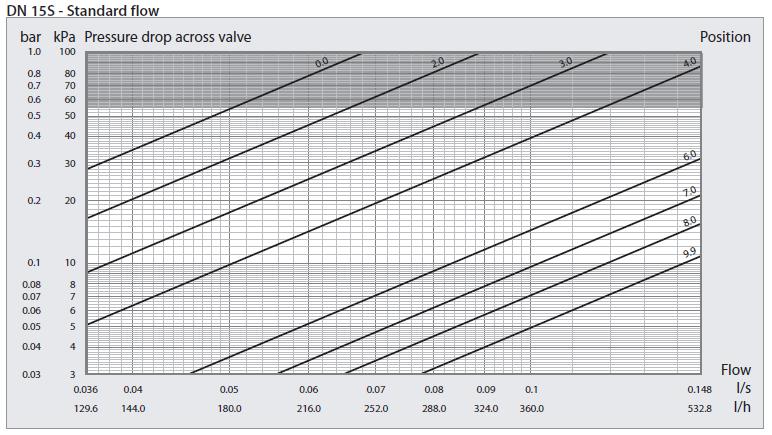

10 10


11 DN 15-Measuring signal diagrams The red dash-dot line shows the Venturi measuring signal the differential pressure across the Venturi nozzle at a given flow. The pressure loss across the Venturi nozzle is in combination with the Kvm value of the valve used to provide the direct flow reading using a flowmeter during system commissioning. 11
12 12


13 DN 20-Flow diagrams The black continuous graph lines determine the total pressure drop across the valve at a specific handle scale setting and flow rate. The graph is used during a hydronic system design to specify the setting of the valve. 13

14 DN 20-Measuring signal diagrams The red dash-dot line shows the Venturi measuring signal the differential pressure across the Venturi nozzle at a given flow. The pressure loss across the Venturi nozzle is in combination with the Kvm value of the valve used to provide the direct flow reading using a flowmeter during system commissioning. 14

15 15

16 DN 25-Flow diagrams The black continuous graph lines determine the total pressure drop across the valve at a specific handle scale setting and flow rate. The graph is used during a hydronic system design to specify the setting of the valve. DN 25-Measuring signal diagrams The red dash-dot line shows the Venturi measuring signal the differential pressure across the Venturi nozzle at a given flow. The pressure loss across the Venturi nozzle is in combination with the Kvm value of the valve used to provide the direct flow reading using a flowmeter during system commissioning. 16
17 17

18 DN 32-Flow diagram The black continuous graph lines determine the total pressure drop across the valve at a specific handle scale setting and flow rate. The graph is used during a hydronic system design to specify the setting of the valve. DN 32-Measuring signal diagram The red dash-dot line shows the Venturi measuring signal the differential pressure across the Venturi nozzle at a given flow. The pressure loss across the Venturi nozzle is in combination with the Kvm value of the valve used to provide the direct flow reading using a flowmeter during system commissioning. 18

19 DN 40-Flow diagram The black continuous graph lines determine the total pressure drop across the valve at a specific handle scale setting and flow rate. The graph is used during a hydronic system design to specify the setting of the valve. DN 40-Measuring signal diagram The red dash-dot line shows the Venturi measuring signal the differential pressure across the Venturi nozzle at a given flow. The pressure loss across the Venturi nozzle is in combination with the Kvm value of the valve used to provide the direct flow reading using a flowmeter during system commissioning. 19

20 DN 50-Flow diagram The black continuous graph lines determine the total pressure drop across the valve at a specific handle scale setting and flow rate. The lines are used during hydronic system design to specify the valve setting. DN 50-Measuring signal diagram The red dash-dot line shows the Venturi measuring signal the differential pressure across the Venturi nozzle at a given flow. The pressure loss across the Venturi nozzle is in combination with the Kvm value of the valve used to provide the direct flow reading using a flowmeter during system commissioning 20


21 DN 65 flange/flange-flow diagram The black continuous graph lines determine the total pressure drop across the valve at a specific handle scale setting and flow rate. The graph is used during a hydronic system design to specify the setting of the valve. DN 65 flange/flange-measuring signal diagram The red dash-dot line shows the Venturi measuring signal the differential pressure across the Venturi nozzle at a given flow. The pressure loss across the Venturi nozzle is in combination with the Kvm value of the valve used to provide the direct flow reading using a flowmeter during system commissioning. 21

22 DN 80 flange/flange-flow diagram The black continuous graph lines determine the total pressure drop across the valve at a specific handle scale setting and flow rate. The graph is used during a hydronic system design to specify the setting of the valve DN 80 flange/flange-measuring signal diagram The red dash-dot line shows the Venturi measuring signal the differential pressure across the Venturi nozzle at a given flow. The pressure loss across the Venturi nozzle is in combination with the Kvm value of the valve used to provide the direct flow reading using a flowmeter during system commissioning 22


23 DN 100 flange/flange-flow diagram The black continuous graph lines determine the total pressure drop across the valve at a specific handle scale setting and flow rate. The graph is used during a hydronic system design to specify the setting of the valve DN 100 flange/flange-measuring signal diagram The red dash-dot line shows the Venturi measuring signal the differential pressure across the Venturi nozzle at a given flow. The pressure loss across the Venturi nozzle is in combination with the Kvm value of the valve used to provide the direct flow reading using a flowmeter during system commissioning 23


24 DN 125 flange/flange-flow diagram The black continuous graph lines determine the total pressure drop across the valve at a specific handle scale setting and flow rate. The graph is used during a hydronic system design to specify the setting of the valve DN 125 flange/flange-measuring signal diagram The red dash-dot line shows the Venturi measuring signal the differential pressure across the Venturi nozzle at a given flow. The pressure loss across the Venturi nozzle is in combination with the Kvm value of the valve used to provide the direct flow reading using a flowmeter during system commissioning 24

25 DN 150 flange/flange-flow diagram The black continuous graph lines determine the total pressure drop across the valve at a specific handle scale setting and flow rate. The graph is used during a hydronic system design to specify the setting of the valve DN 150 flange/flange-measuring signal diagram The red dash-dot line shows the Venturi measuring signal the differential pressure across the Venturi nozzle at a given flow. The pressure loss across the Venturi nozzle is in combination with the Kvm value of the valve used to provide the direct flow reading using a flowmeter during system commissioning. 25

26 DN 200 flange/flange-flow diagram The black continuous graph lines determine the total pressure drop across the valve at a specific handle scale setting and flow rate. The graph is used during a hydronic system design to specify the setting of the valve. DN 200 flange/flange-measuring signal diagram The red dash-dot line shows the Venturi measuring signal the differential pressure across the Venturi nozzle at a given flow. The pressure loss across the Venturi nozzle is in combination with the Kvm value of the valve used to provide the direct flow reading using a flowmeter during system commissioning 26

27 DN 250 flange/flange-flow diagram The black continuous graph lines determine the total pressure drop across the valve at a specific handle scale setting and flow rate. The graph is used during a hydronic system design to specify the setting of the valve DN 250 flange/flange-measuring signal diagram The red dash-dot line shows the Venturi measuring signal the differential pressure across the Venturi nozzle at a given flow. The pressure loss across the Venturi nozzle is in combination with the Kvm value of the valve used to provide the direct flow reading using a flowmeter during system commissioning 27

28 DN 300 flange/flange-flow diagram The black continuous graph lines determine the total pressure drop across the valve at a specific handle scale setting and flow rate. The graph is used during a hydronic system design to specify the setting of the valve DN 300 flange/flange-measuring signal diagram The red dash-dot line shows the Venturi measuring signal the differential pressure across the Venturi nozzle at a given flow. The pressure loss across the Venturi nozzle is in combination with the Kvm value of the valve used to provide the direct flow reading using a flowmeter during system commissioning. 28
29 Mounting instructions DN An arrow on the Ballorex Venturi housing indicates the flow direction to be respected. Ballorex Venturi can be orientated 360 around the pipe axis. Installation space is required to ensure the 90 isolation. 29
30 0 DN straight piping is required. The Ballorex Venturi can be mounted directly onto bends, reducers, flexible pipes etc. 5 DN straight piping is required when the valve is mounted directly after the system pump. Loose hemps must not hang into the pipe. Deburring of pipe ends is required to prevent system clogging 30
31 A Ballorex balancing computer with pre-stored Ballorex valves data can be used for flow verification. When using any other flowmeter, the Ballorex Venturi Kvm value stated on the valve handle is entered once only to obtain the correct flow reading. Setting the valve is easily done using an Allen key. The valve is adjusted until the required flow is displayed on the flowmeter. Mounting instructions DN An arrow on the Ballorex Venturi tube indicates the flow direction to be respected. Ballorex Venturi can be installed with the gearbox pointing in any direction. However, if the gearbox is mounted pointing downwards, it is assumed that there are no impurities in the system to affect the performance of the valve. If there is a risk of impurities, it is recommended to install the gearbox in an angle from 60 to
32 It is recommended to provide a straight pipe length of minimum 5 DN pipe diameter before the valve. There are no minimum requirements for straight lengths of pipe after the valve. If a pump is installed immediately in front of the valve, a straight pipe of 10 DN pipe diameter is required. There are no requirements for straight pipe lengths after the valve. Ballorex balancing computer with pre-stored Ballorex valves data can be used for flow verification. When using any other flowmeter, the Ballorex Venturi Kvm value stated on the Venturi tube is entered once only to obtain the correct flow reading. The flow rate is adjusted by rotating the handle on the gearbox. The flow rate increases by rotating the handle to the left (counter-clockwise) and is reduced by rotating it to the right (clockwise). 32

33 Accessories Photo Designation Dimensions Codes Ballorex Venturi insulation jacket Insulation jacket for Ballorex Venturi with drain (can also be used for Ballorex Venturi without drain) DN 15 96M DN 15 96M DN 20 96M DN 20 96M DN 15 96M DN 32 96M DN 32 96M DN 40 96M DN 40 96M DN 50 96M DN 50 96M Measuring point for high temperature medium - up to 135 C (installed in the P/T port of the Ballorex Venturi) M14 1 / quick coupling Pre-sealed press adaptors (2 pcs), max. 16 bar High capacity drain valve (Kvs = 4,5 m 3 /h)1/2 female/female threaded connection for installation in a system pipe 15 mm 1/2 18 mm 1/2 15 mm 3/4 18 mm 3/4 22 mm 3/ mm mm 11/ mm 11/ mm DN DN DN Combi Drain Maxi with measuring point R 1/4 / G 3/ Butterfly valve for Ballorex Venturi Kvs: 148 m 3 /h Butterfly valve for Ballorex Venturi Kvs: 237 m 3 /h Butterfly valve for Ballorex Venturi Kvs: 603m 3 /h Butterfly valve for Ballorex Venturi Kvs: 888 m 3 /h Butterfly valve for Ballorex Venturi Kvs: 2340 m 3 /h Butterfly valve for Ballorex Venturi Kvs: 2850m 3 /h Butterfly valve for Ballorex Venturi Kvs: 4550 m 3 /h Butterfly valve for Ballorex Venturi Kvs: 7760 m 3 /h DN DN DN DN DN DN DN DN
34 34
Ballorex Venturi 3.1 Introduction
 3.1 Introduction Venturi Fixed Orifice Double Regulating Valve (FODRV) DN 15-600 1/2-24 Venturi description The Venturi is a range of manual balancing valves used in water-based heating and cooling systems
Ballorex Vario. Description. Versions. Benefits. Applications. Balancing
 Ballorex Vario Description Ballorex Vario is a variable orifice double regulating valve for balancing water-based heating and cooling systems. The balancing performed ensures the required distribution
Balancing Valves. Venturi Commissioning Valve (FODRV) & (DRV) Cu x Cu Compression DN10-DN50. BOSS TM 901SC Venturi DRV DN
 & (DRV) Cu x Cu Compression DN10-DN50. BOSS TM 901SC Venturi DRV DN") Venturi Commissioning Valve (FODRV) & (DRV) Cu x Cu Compression DN-DN Balancing Valves BOSS TM 900SC Venturi FODRV DN1- BOSS TM 901SC Venturi DRV DN1- Specification The commissioning station and DRV incorporates
Venturi Commissioning Valve (FODRV) & (DRV) Cu x Cu Compression DN-DN Balancing Valves BOSS TM 900SC Venturi FODRV DN1- BOSS TM 901SC Venturi DRV DN1- Specification The commissioning station and DRV incorporates
Pressure Independent Control Valve
 Pressure Independent Control Valve www.ballorex.com Table of contents Chapter Ballorex Dynamic DN 15L-50H 1. Safety instructions 4 1.1 Rules/regulations 4 1.2 Intended use 5 1.3 Initial operation 5 1.4
Pressure Independent Control Valve
 Pressure Independent Control Valve www.ballorex.com Table of contents Chapter Ballorex Dynamic DN 15L-50H 1. Safety instructions 4 1.1 Rules/regulations 4 1.2 Intended use 5 1.3 Initial operation 5 1.4
Differential Pressure Control Valve
 Differential Pressure Control Valve www.ballorex.com 2 Table of contents Chapter Ballorex Delta DHC DN 15-150 1. Safety instructions 4 1.1 Rules/regulations 4 1.2 Intended use 5 1.3 Initial operation 5
BROEN BALLOREX Dynamic R E ADY STEADY GO!
 BROEN BALLOREX Dynamic R E ADY STEADY GO! Perfect flow with dynamic balancing BROEN BALLOREX Dynamic is a combined pressure independent flow limiter and control valve. The new and innovative range of dynamic
Pre-Fabricated Flushing Bypass Assembly for Plant Applications Hero Plant DN15-150
 Pre-Fabricated Flushing Bypass Assembly for Plant Applications Description Hero Plant is a pre-fabricated, flushing bypass arrangement for balance, control, isolation, and operation of plant devices. Flow
Innovation + Quality. Valves, controls + systems Balancing and Control Valves
 Innovation + Quality Valves, controls + systems Balancing and Control Valves Balancing and Control Valves Catalog Hydrocontrol Static Balancing Valves Recomended flow rate chart 4 Hydrocontrol VTR Static
Innovation + Quality. Valves, controls + systems Balancing and Control Valves
 Innovation + Quality Valves, controls + systems Balancing and Control Valves Cocon Q Pressure independent control valve Product specification Size: L1 L2 H1 H2 ½, ½ LF 2.75 3.9 2.0 1.9 ¾ LF 2.9 4.2 2.0
Product Sheet Pre-Fabricated Flushing Bypass Assembly for Plant Applications Hero Plant DN15-150
 Product Sheet Pre-Fabricated Flushing Bypass Assembly for Plant Applications Hero Plant DN15-150 Description Hero Plant is a pre-fabricated, flushing bypass arrangement for balance, control, isolation,
Circuit Regulating Valve STRÖMAX GF
 Circuit Regulating Valve STRÖMAX - GF Circuit Regulating Valve for differential pressure measurement, with test points, flanged version Data sheet for GF Issue 0 GF STRÖMAX GF with test points H H D L.
Automatic balancing valves ASV-PV DN (3rd gen.)
") Automatic balancing valves ASV-PV DN 50-100 (3rd gen.) Description / Application Partner valve ASV-PV DN 50 ASV-PV DN 65-100 MSV-F2 DN 50-100 ASV balancing valves are used for dynamic hydronic balance
Automatic balancing valves ASV-PV DN 50-100 (3rd gen.) Description / Application Partner valve ASV-PV DN 50 ASV-PV DN 65-100 MSV-F2 DN 50-100 ASV balancing valves are used for dynamic hydronic balance
Manual presetting valves LENO MSV-BD
 Manual presetting valves LENO MSV-BD Description LENO MSV-BD is a range of manual valves for balancing flow in heating, cooling and domestic hot water systems. LENO MSV-BD is a combined presetting and
FO-BV Series. Fixed-orifice balancing and control valves. Technical Data Sheet. WattsIndustries.com
 FO-BV Series Fixed-orifice balancing and control valves Technical Data Sheet WattsIndustries.com Description FO-BV Series fixed-orifice threaded valves are designed for flow control and monitoring in climate
HERZ 7217 V. Integral Fixed Orifice Control Valve HERZ 7217 V. Data sheet 7217 V, Issue Size in mm. STRÖMAX Fig No DN L Lm Rp H SW kv kvs
 HERZ 7217 V Integral Fixed Orifice Control Valve Data sheet 7217 V, Issue 1011 Size in mm STRÖMAX Fig No DN L Lm Rp H SW kv kvs TS-V LF 1 7217 50 15 83 28,5 1/2 41 27 0,07-0,45 0,48 TS-V MF 1 7217 59 15
Valves for building. Y-strainers... page 204 PVC valves Ball valves... page 204 Butterfly valve... page 204 Ball check valve...
 Valves for building Ball valves PN25/20... page 194 PN30/20... page 195 PN40/30 - Lead-free brass... page 196 Valve for gas... page 197 Stem extension valves... page 197 3 way valves... page 197 Mini valves...
STAF, STAF-SG. Balancing valves PN 16 and PN 25 DN
 STAF, STAF-SG Balancing valves PN 16 and PN 25 DN 20-400 IMI TA / Balancing valves / STAF, STAF-SG STAF, STAF-SG A flanged, cast iron (STAF) and ductile iron (STAF-SG) balancing valve that delivers accurate
STAF-SG. ANSI flanges. Balancing valves DN
 STAF-SG ANSI flanges Balancing valves DN 20-400 IMI TA / Balancing valves / STAF-SG ANSI flanges STAF-SG ANSI flanges A flanged, ductile iron balancing valve that delivers accurate hydronic performance
Valves for building. Y-strainers... page 272 PVC valves Ball valves... page 272 Butterfly valves... page 272 Ball check valves...
 Valves for building Ball valves PN25/20... page 262 PN30/20...pages 262 to 263 PN40/30 - Lead-free brass... page 264 Valve for gas... page 265 Stem extension valves... page 265 3 way valves... page 265
PRESSURE RELIEF VALVE CONTROL VALVE
 PRESSURE RELIEF VALVE CONTROL VALVE LEHRY Pressure Relief Valve, Sustaining or Backpressure Control Valve is designed to permitting flow when upstream pressure is above the adjustable setpoint of the control
Manual Presetting Valves LENO MSV-B
 Data Sheet Description LENO MSV-B is a new generation of manual valves for balancing flow in heating, cooling and domestic hot water systems. LENO MSV-B is a combined presetting and shut off valve with
Valves, controllers + systems Double regulating and commissioning valves Hydrocontrol F cast iron, PN 16
 Valves, controllers + systems Double regulating and commissioning valves Hydrocontrol F cast iron, PN The Oventrop Quality Management System is certified to DIN-EN-ISO 9001 Technical information Application:
4017 M HERZ Dimensions in mm
 HERZ STRÖMAX 4017 Commissioning valve with integral fixed orifice plate Control valve for chilled and hot water systems in buildings Data sheet for 4017, Issue 0716 Dimensions in mm H2 H1 L1 L2 D 4017
Valves, controls + systems Cast iron double regulating/ commissioning valves PN 16 Hydrocontrol G
 The Oventrop Quality Management System is certified to DIN-EN-ISO 9001 Application: Oventrop double regulating and commissioning valves Hydrocontrol G are installed in the pipework of hot water central
Safety cap. Measuring probe. Seal. Operating principle. Advantages of balanced circuits. Balanced circuits have the following principal benefits:
 Balancing valve, fixed orifice 0 series CALEFFI 0/ NA ACCREDITED ISO 900 FM ISO 900 No. 000 Function Product range Caleffi 0 series low lead, manual balancing valves are used to measure and adjust the
Double regulating and commissionig valves Hydrocontrol F cast iron, PN 16 Hydrocontrol FR bronze, PN 16 Hydrocontrol FS nodular cast iron, PN 25
 Hydrocontrol FR bronze, PN 16 Hydrocontrol FS nodular cast iron, PN 25 The Oventrop Quality Management System is certified to DIN-EN-ISO 9001 Technical Information Application: Oventrop double regulating
Manual presetting valve MSV-C
 Description / Application MSV-C is used for balancing the flow in cooling, heating and domestic water systems. MSV-C is a combined manual presetting valve with following features: Fixed measurement orifice.
Installation Operation & Maintenance Instructions
 Installation Operation & Maintenance Instructions Contents Please read the installation operation and maintenance instruction prior to using any of our components. Failure to follow the instructions may
Pressure independent combined control and balancing valves with independent EQM characteristics
 Combined control & balancing valves TA-FUS1ON-P Pressure independent combined control and balancing valves with independent EQM characteristics Pressurisation & Water Quality Balancing & Control Thermostatic
STAF, STAF-SG. Balancing valves PN 16 and PN 25 DN
 STAF, STAF-SG Balancing valves PN 16 and PN 25 20-400 IMI TA / Balancing valves / STAF, STAF-SG STAF, STAF-SG A flanged, cast iron (STAF) and ductile iron (STAF-SG) balancing valve that delivers accurate
ZONE CONTROLE / 2-WAY
 ZONE CONTROLE / 2-WAY PRESSURE INDEPENDENT BALANCING AND CONTROL VALVE ON/OFF High-performing and compact, these pressure-independent temperature control valves for variable flow heating and cooling systems,
STAF-SG. ANSI flanges. Balancing valves Size 3/4-16
 STAF-SG ANSI flanges Balancing valves Size 3/4-16 IMI TA / Balancing valves / STAF-SG ANSI flanges STAF-SG ANSI flanges A flanged, ductile iron balancing valve that delivers accurate hydronic performance
Ballorex commissioning valves
 Ballorex commissioning valves Pegler Yorkshire Unrivalled quality, innovation, customer service and long-term value for money As part of the global Aalberts Industries NV Group, Pegler Yorkshire is one
Technote. Frese ALPHA - automatic balancing valve. Application. Benefits. Features.
 Page 1 of 6 Application The Frese APHA Valves are particularly designed and manufactured for the automatic balancing of heating and cooling circuits. The Frese APHA Cartridges - the second generation cartridges
Brown University Revised August 3, 2012 Facilities Design & Construction Standards SECTION HVAC&R VALVES
 SECTION 23 05 23 HVAC&R VALVES PART 1 - GENERAL 1.1 SUMMARY: A. Section includes valves for building services piping. 1.2 GENERAL VALVE APPLICATION REQUIREMENTS: A. Provide valve handle extensions that
BUTTERFLY VALVE 17 SERIES Gearbox
 DN H1 H2 H3 BUTTERFLY VALVE 17 SERIES Gearbox FIGURE: 17234ER: 17234BR: 17234VR: Seat in EPDM, with gearbox Seat in Buna, with gearbox Seat in Viton, with gearbox B ØR L DIMENSIONS: (mm) DN L B XR H1 H2
S t e e l H o o k-ups AIR HANDLING UNIT SOLUTIONS
 S t e e l H o o k-ups AIR HANDLING UNIT SOLUTIONS Q u a l i t y, C o n v e n i e n c e a n d V a l u e S t e e l H o o k-ups When it comes to standard and custom coil/piping hook-up packages for Fan Coil
Pressure independent balancing and control valve For ON/OFF control
 KT 512 Pressure independent balancing and control valve For ON/OFF control Pressurisation & Water Quality Balancing & Control Thermostatic Control ENGINEERING ADVANTAGE High-performing and compact, these
Direct/Factory Mounting Valve Set
 Generated: 29th April 2018 Marflow Hydronics 1 Dimensions DN 15/20 A 243 B 137 C 115 D 3/4 Euroconus d 40 E 30.2 Generated: 29th April 2018 Marflow Hydronics 2 Product Variations NX-EVO-X-X-03 Part No:
Hydrocontrol VFC cast iron, PN 16 Hydrocontrol VFR bronze, PN 16 Hydrocontrol VFN nodular cast iron, PN 25 Double regulating and commissioning valves
 Hydrocontrol VFC cast iron, PN 16 Hydrocontrol VFR bronze, PN 16 Technical Information Application: Oventrop double regulating and commissioning valves Hydrocontrol VFC/VFR/VFN are installed in the pipework
S t e e l H o o k-ups AIR HANDLING UNIT SOLUTIONS
 S t e e l H o o k-ups AIR HANDLING UNIT SOLUTIONS Quality, Convenience and Value S t e e l H o o k-ups When it comes to standard and custom coil/piping hook-up packages for Fan Coil Units, Reheat Coils,
15100 VALVES. E. Section Building Automation and Control System Guidelines
 15100 VALVES PART 1: GENERAL 1.01 RELATED SECTIONS A. Section 15050 Basic Material and Methods B. Section 15545 Chilled Water System C. Section 15550 Heat Generation D. Section 15790 Coils E. Section 15955
Figure 1710 Flow Data
 AHEAD OF THE FLOW Figure 1710 Flow Data Circuit Balancing Valve Why balance your system? Whether a system is designed for heating or chilling it must be properly adjusted and balanced for optimum design
Pressure independent balancing and control valve AB-QM DN
 Pressure independent balancing and control valve AB-QM DN 10-150 AB-QM valve equipped with an actuator is a control valve with full authority and automatic balancing function - flow limiter. Typical applications
HERZ-Motorised flow controler
 HERZ-Motorised flow controler Control and regulating valve Data sheet 4006 SMART, Issue 0516 Dimensions in mm 4006 M 4006 R M R Order number DN G L L1 B B1 H without Actuator H with Actuator H1 1 4006
Manufacturer of Industrial Valves a n d R e l e v a n t E q u i p m e n t. Tilting Disk Check Valves with Counter Weight.
 Manufacturer of Industrial Valves a n d R e l e v a n t E q u i p m e n t Tilting Disk Check Valves www.mirabvalves.com TiltingDisc Check Valves Size: DN 100 1 mm Pressure: PN 10 40 bar Face to face:
AV 23 Balancing valves SETTER Inline
 AV Balancing valves SETTER Inline Application Direct reading and balancing valve with visual flow indication. Correct balancing of circuits ensure optimum efficiency of the system and can therefore help
CALEFFI. Pre-assembled distribution manifolds for. heating and air-conditioning systems. 663 series 01065/18 GB. replaces dp 01065/06 GB.
 Pre-assembled distribution manifolds for heating and air-conditioning systems 663 series FM 21654 003 065/18 GB replaces dp 065/06 GB Function The pre-assembled distribution manifolds are designed to optimise
TA-FUS1ON-P. Combined control & balancing valves Pressure independent combined balancing and control valves with independent EQM characteristics
 TA-FUS1ON-P Combined control & balancing valves Pressure independent combined balancing and control valves with independent EQM characteristics IMI TA / Control valves / TA-FUS1ON-P TA-FUS1ON-P These innovative
CBV Series. Circuit Balancing Valves
 CBV Series Circuit Balancing Valves FILE NO: 36.10IN DATE: Dec. 15, 2010 SUPERSEDES: 36.10IN DATE: Nov. 05, 2009 CBV Series Circuit Balancing Valves - Introduction Circuit balancing valves (CBVs) combine
Concentric butterfly valves
 Lug Between flanges PN10/16 1135 Lever Disc GGG40 nickel plated / Seat EPDM.../10: flanges PN10.../16: flanges PN16 DN 40 50 65 80 100 125 150 200/10 200/16 250/10 250/16 300/10 300/16 16 16 16 16 16 16
Size : Ends : Min Temperature : Max Temperature : Materials : Cast iron body. Certificate 3.1
 Certificate 3.1 Size : Ends : Min Temperature : Max Temperature : DN 40 to DN 600 Between flanges PN10/16-15 C + 110 C ( 130 C C temporarily) Max Pressure : 16 Bars up to DN300, 10 bars over Specifications
Technote. Frese OPTIMA Compact DN10-DN50 - pressure independent balancing & control valve. Application. Features. Benefits.
 Page of 5 Frese OPTIMA Compact DN-DN5 Application Frese OPTIMA Compact pressure independent balancing & control valve (PIBCV) is used in heating and cooling systems in applications with Fan Coil Units,
Static Balancing Valve
 Static Balancing Valve Series W-JP45X-16Q Sizes: DN50-DN300 APPLICATION The Series W-JP45X Static Balancing Valve is designed for flow balancing in cooling, heating or process water systems. Its measuring
Flow Data for NIBCO Circuit Balancing Valves 1/2 to 2 (Figure Number 1710)
") NIBCO INC. WORLD HEADQUARTERS 1516 MIDDLEBURY ST. ELKHART, IN 46516-4740 USA PHONE: 574.295.3000 FAX: 574.295.3307 WEB: www.nibco.com INSTALLATION, OPERATION & MAINTENANCE INSTRUCTIONS Flow Data for NIBCO
NIBCO INC. WORLD HEADQUARTERS 1516 MIDDLEBURY ST. ELKHART, IN 46516-4740 USA PHONE: 574.295.3000 FAX: 574.295.3307 WEB: www.nibco.com INSTALLATION, OPERATION & MAINTENANCE INSTRUCTIONS Flow Data for NIBCO
Serie Ekoflux S. Flanged balancing valve. Application fields. Regulation. Ekoflux.S_GB_22/04/2015 HEATING CONDITIONING
 Serie Ekoflux S Flanged balancing valve Ekoflux.S_GB_/0/0 Application fields CONDITIONING HEATING www.brandoni.it Serie Ekoflux S The valves in the series EKOFLUX balance the flow in main circuits or single
Product Sheet Pre-Fabricated Flushing Bypass Assembly for Terminal Applications Mini-Flush 40
 Product Sheet Pre-Fabricated Flushing Bypass Assembly for Terminal Applications Mini-Flush 40 Description Miniflush40 is a pre-fabricated, flushing bypass arrangement for balance, control, isolation, and
Cast Iron Valves. Product Information. It s all at Albion
 Cast Iron Valves Product Information It s all at Albion ART 77-78 Cast Iron Ball Valve Flanged Ends Flange Mounting PN16 Only ISO 5211 Direct Mount (Not 200mm) Art 77/78 Plated Brass/Stainless Ball BS
TA-Mini-Fast-Fit. Prefab units Fabricated solutions for small terminal units
 TA-Mini-Fast-Fit Prefab units Fabricated solutions for small terminal units IMI TA / Control valves / TA-Mini-Fast-Fit TA-Mini-Fast-Fit Compact pressure independent solution for modulating or on/off control.
GRINNELL MODEL CB800 CIRCUIT BALANCING VALVE INSTALLATION & SETTING HANDBOOK
 Technical Services 866-500-4768 +-40-78-8220 GRINNELL MODEL CB800 CIRCUIT BALANCING VALVE INSTALLATION & SETTING HANDBOOK AUGUST 20 IH-4500 Table of Contents Contents General Description.... 3 Dimensional
TA-PILOT-R. Differential pressure controllers Pilot operated differential pressure controller with adjustable set-point
 TA-PILOT-R Differential pressure controllers Pilot operated differential pressure controller with adjustable set-point IMI TA / Differential pressure controllers / TA-PILOT-R TA-PILOT-R The TA-PILOT-R
SECTION GENERAL-DUTY VALVES FOR HVAC PIPING. A. Contents of Division 23, HVAC and Division 01, General Requirements apply to this Section.
 SECTION 23 05 23 PART 1 - GENERAL 1.1 SUMMARY A. Work Included: 1. Gate Valves 2. Balancing Valves 3. Ball Valves 4. Butterfly Valves 5. Swing Check Valves 1.2 RELATED SECTIONS A. Contents of Division
Valves Range RVRX - Resilient Seated Gate Valve PN16 Flange
 Valves Range RVRX - Resilient Seated Gate Valve PN16 Flange No Component Material 1 Body Ductile iron GGG40 2 Wedge DI Fully Vulcanised EPDM 3 Wedge Nut Brass 4 Stem SS420 5 Bolt Q235+Zinc 6 Gasket EPDM
DA 50. Differential pressure controllers Adjustable set-point
 DA 50 Differential pressure controllers Adjustable set-point IMI TA / Differential pressure controllers / DA 50 DA 50 These differential pressure controllers for heating and cooling systems are particularly
LUG BUTTERFLY VALVE PN10/16
 LUG BUTTERFLY VALVE PN10/16 Model/Ref: 1133 www.lauridsenindustri.com Size : Ends : Min Temperature : Max Temperature : DN 40 to DN 600 Between flanges ISO PN10/16-10 C + 110 C ( 130 C C temporarily) Max
PCS. HVAC Products. Technical submission. Type of Product
 Technical submission R 1.1 Type of Product XT series complete Terminal valve assembly for fixed and adjustable flushing by-pass for axial PICV. This technical submittal contains information that to the
Cast-Iron Valves G101 DI BUTTERFLY VALVE LEVER... 2 G401 CI GLOBE VALVE CL G403 CI GLOBE VALVE PN G103 DI BUTTERFLY VALVE GEAR...
 Cast-Iron Valves PAGE G101 DI BUTTERFLY VALVE LEVER.... 2 PAGE G401 CI GLOBE VALVE CL125.... 9 G103 DI BUTTERFLY VALVE GEAR.... 3 G403 CI GLOBE VALVE PN16.... 10 G201 CI Y STRAINER CL125.... 4 G501 CI
CALEFFI. Pre-assembled distribution manifolds for radiant panel systems. series 663 & /05 NA. Function
 Pre-assembled distribution manifolds for radiant panel systems series & / NA Function Distribution manifolds for radiant panel systems are used to optimally distribute the heating fluid in floor heating
Combi valves, PN 25. for rooms, zones, ventilation and air-conditioning systems
 4 855 VPP46.. VPI46.. VPP46..Q, with pressure test points P/T VPI46..Q, with pressure test points P/T ACVATIX Combi valves, PN 25 for rooms, zones, ventilation and air-conditioning systems VPP46.. VPP46..Q
Pressure independent balancing and control valve
 Pressure independent balancing and control valve AB-QM DN 10-150 AB-QM valve equipped with an actuator is a control valve with full authority and automatic balancing function - flow limiter. Typical applications
TDU.3 floor distribution unit SK
 SK General description and application The is intended for two pipe horizontal heating systems and includes connecting, measuring, regulating and distribution functions. The TDU.3 is easily installed on
Technote. Frese ALPHA HCR Dynamic Balancing Valve. Application. Features. Benefits. Design. Installation. Operation.
 Page 1 of 7 Application The (High Corrosion Resistant) Valves are particularly designed and manufactured for automatic balancing in Industrial applications. An integral part of the Valve is the ALPHA Cartridge,
Fan-coil valves Series
 Fan-coil valves Series 11-11 - 411 Main features Complete range in the following versions : -way - DN: 1/, /4, 1 -way - DN: 1/, /4, 1 -way with 4 ports - DN: 1/, /4 - The -way version and the -way versions
MrPEX 1 ¼ Stainless Steel Manifold. Installation Guide
 MrPEX 1 ¼ Stainless Steel Manifold Installation Guide Design MrPEX 1 ¼ Stainless Steel Manifold is made from high quality stainless steel, and is offered in 2 through 12 loop configurations. The manifold
502 brass ball valve with ADA pneumatic actuator
 502 brass ball valve with ADA pneumatic actuator MAIN CHARACTERISTICS The 502 valve is a brass ball valve dedicated to the automatic shut off of lines of standard fluids like water or air. With chromed
TECHNICAL CATALOGUE DISTRIBUTION MANIFOLDS
 TECHNICAL CATALOGUE DISTRIBUTION TEC ITAP SpA, founded in Lumezzane (Brescia) in 972, is currently one of the leading production companies in Italy of valves, fittings and distribution manifolds for plumbing
NON RETURN BRASS FLANGED AGA GAS APPROVED
 NON RETURN BRASS FLANGED AGA GAS APPROVED ACTUATED MARINE STAINLESS STEEL 34 VALVES 36... BRASS BALL VALVES 37... AGA GAS APPROVED VALVES GATE VALVES 38... BRASS VALVES 39... RUBBER BELLOW, HOSECOCKS &
ROTARY PRESSURE INDEPENDENT CONTROL VALVE TECHNICAL MANUAL
 ROTARY PRESSURE INDEPENDENT CONTROL VALVE TECHNICAL MANUAL Introduction The EVOPICV-R Rotary Pressure Independent Control Valve EVOPICV-R is a combined constant flow limiter and rotary characterised control
Pressure Independent Control Valve Applications for Building Automation, Temperature Controls, and HVAC Two-Way Chilled Water Hot Water
 Rev: 08/19/2013 (ATiMX) Features Pressure Independent Control Valve Applications for Building Automation, Temperature Controls, and HVAC Two-Way Chilled Water Hot Water The Auto Touch Independent Max (ATiMX)
OPTIMAL VALVE SOLUTIONS FOR OIL AND GAS PLANTS
 AVK FLOW CONTROL OPTIMAL VALVE SOLUTIONS FOR OIL AND GAS PLANTS InterApp World Valve Wouter Witzel TEC artec AVK 1 2 AVK FLOW CONTROL l OIL & GAS PLANTS CONTENT: AVK FLOW CONTROL 4-5 OFFSHORE PRODUCTION
AutoFlow. Automatic Flow Control Valves
 AutoFlow Automatic Flow Control Valves IMI FLOW DESIGN / AutoFlow / F010 Automatic Balancing Brochure Benefits of Automatic Balancing System equipment, such as chillers and individual terminal units, is
CLASS 400 FORGED BRASS BALL VALVE
 CLASS 400 FORGED BRASS BALL VALVE FIG. 214 Screwed body cap, PTFE seats, Blowout-proof stem. Screwed ends to BS 21. Nickel plated body. Chrome plated ball. UNI-FLO NYLON BALL VALVES FIG. 214NS/NB Features:
MUELLER ECCENTRIC PLUG VALVE
 MUELLER INSTALLATION, OPERATING and MAINTENANCE INSTRUCTIONS 1 MUELLER System Design The life of the valve is dependent on its application, frequency of use and freedom from misuse. The properties of the
Technote. Frese OPTIMA - Pressure independent control & balancing valve. Application. Features. Benefits.
 Page 1 of 12 Application pressure independent control valve (PICV) is used in heating and cooling systems in applications with Fan Coil Units, Air Handling Units or other terminal unit applications. provides
CALEFFI. FLOWCAL Automatic flow balancing valve with polymer cartridge. 121 series 01141/11 NA. Function
 FLOWCAL Automatic flow balancing valve with polymer cartridge 121 series REGISTERED BSI EN ISO 9001:2000 Cert. n FM 21654 UNI EN ISO 9001:2000 Cert. n 0003 CALEFFI 01141/11 NA Function The FlowCal automatic
Type overview. R B2 en-gb subject to changes 1
 Technical data sheet R30..-..-..-B2 Characterised control valve, 6-way, Internal thread Two sequences (cooling/heating) with one 90 rotary actuator Switching or modulating control on the water side of
40 geothermal ground loop manifolds
 40 geothermal ground loop manifolds GeoCal (key features listed left) This is the first thermoplastic, fully modular manifold system designed specifically for installations using ground source heat pumps.
HVAC. Products. TRI A FLO Automatic Cartridges PAGE 2. TRI Y FLO Strainer PAGE 3. TRI U FLO Accessory Union PAGE 4. CB Series Butterfly/Venturi PAGE 5
 HVAC TRI A FLO Automatic Cartridges TRI Y FLO Strainer TRI U FLO Accessory Union Products Automatic balancing valves.5 thru 108.0 in Brass, Stainless, PVC, CPVC, Titanium, Ceramic, Monel, and more PAGE
SECTION METERS AND GAGES FOR PLUMBING PIPING
 PART 1 GENERAL 1.01 SECTION INCLUDES A. Positive displacement meters. B. Flow meters. SECTION 22 0519 METERS AND GAGES FOR C. Pressure gages and pressure gage taps. D. Thermometers and thermometer wells.
Terminator PICV. Technical Manual
 Terminator PICV Technical Manual Table of Contents Introduction 1 Advantages and Ease of Use 1 Applications examples 2 Technical specifications Start Up Charts 6 Start Up Charts 7 Start Up Charts 8 Flow
VALVCHEQ BACKFLOW PREVENTERS FIGURE DC03
 Double check valves for medium hazard rated applications Flanged and roll grooved end connections FEATURES GENERAL APPLICATION The DC0 provides protection from both backsiphonage and backpressure of the
Pressure Independent Control Valve
 Pressure Independent Control Valve Rev. 4.0-06/06/2011 Technical manual Introduction The Pressure Independent Control Valve PICV is a combined constant flow limiter and full stroke, full authority equal
Flow controller with integrated control valve (PN 16) AHQM return and flow mounting
 AHQM return and flow mounting") Data sheet Flow controller with integrated control valve (PN 16) AHQM return and flow mounting Description DN 15-32 DN 40, 50 DN 50-100 DN 125 DN 150 DN 200, 250 AHQM is a self-acting flow controller with
Data sheet Flow controller with integrated control valve (PN 16) AHQM return and flow mounting Description DN 15-32 DN 40, 50 DN 50-100 DN 125 DN 150 DN 200, 250 AHQM is a self-acting flow controller with
CV-SFS4-PN16 SERIES SLIENT CHECK VALVE, GLOBE TYPE FEATURES SPECIFICATIONS PRODUCT IDENTIFICATION SYSTEM PRODUCT DATA
 CV-SFS4-PN16 SERIES SLIENT CHECK VALVE, GLOBE TYPE Silent check function Temperature -10 ~ +120 PRODUCT IDENTIFICATION SYSTEM 2 Disc Ductile iron GGG 40 3 Spring Stainless steel SUS304 4 Bush Bronze 1400
ATi Max Series. Pressure Independent Control Valves 2 Way 2-1/2-6
 The Auto Touch Independent Max (ATiMX) valve brings pressure independent control technology to valves up to 6 and flow rates up to 468 GPM. It is a state-of-the-art control valve combining a high quality/
132 Series. QuickSetter Balancing Valve with flow meter NA Function
 NA800 www.caleffi.com QuickSetter Balancing Valve with flow meter Copyright 0 Caleffi Series Function The QuickSetter+ balancing valve accurately controls the flow rate in plumbing systems. Proper system
7 ZONE VALVES. Applications
 7 ZONE VALVES Designed to fit in compact areas where On/Off control is required. Actuator installation is a snap with an easy, one-handed removal or engagement. Actuator has a synchronous motor that winds
SECTION VALVES PART 1 -GENERAL
 SECTION 1571 0 VALVES PART 3- EXECUTION General Shut-off Valves Balancing Valves Drain Valves RELATED WORK Section 15430- Plumbing Specialties Section 15450- Plumbing Equipment PART 1 -GENERAL SCOPE This
A. This Section includes general duty valves common to several HVAC piping systems.
 SECTION 23 05 23 - PART 1 - GENERAL 1.1 RELATED DOCUMENTS A. Drawings and general provisions of the Contract, including General and Supplementary Conditions and Division 01 Specification Sections, apply