Differential Pressure Control Valve
|
|
|
- Bernadette Mitchell
- 6 years ago
- Views:
Transcription
1 Differential Pressure Control Valve
2 2
3 Table of contents Chapter Ballorex Delta DHC DN Safety instructions Rules/regulations Intended use Initial operation Working on the system Liability 5 2. Introduction Description Benefits Design Pressure balancing With partner valve Mounting Operation Applications Product data sheet Product finder Ballorex Delta DHC DN Ballorex Delta DHC DN with partner valve Ballorex Delta DHC DN Flow diagrams Valve sizing Valve setting DN Accessoires Sizing examples System with Ballorex Delta DHC and Ballorex Venturi General specifications DN
4 1. Safety instructions Please read the instructions carefully before installation The installation and initial operation of the assembly may be carried out only by an authorised specialist company. Prior to starting work. familiarise yourself with all parts and how they are handled. The application examples in these operating instructions are ideas sketched out. Local laws and regulations have to be observed. Target group: These instructions are intended for authorised specialists exclusively. Work on the heating system. the potable water as well as gas and power network may be carried out by specialists only. Please follow these safety instructions carefully in order to avoid hazards and damage to people and property. 1.1 Rules/regulations Please observe the applicable accident prevention regulations. the environmental legislation and the legal rules for mounting. installation and operation. Moreover. please observe the appropriate guidelines of German standard DIN. EN. DVGW. VDI and VDE (including lightning protection) as well as all current relevant country-specific standards. laws and regulations. Old and newly enforced regulations and standards shall apply. if they are relevant for the individual case. Moreover. the regulations of your local energy supply company have to be observed. Electrical connection: Electrical wiring work may be carried out by qualified electricians only. The VDE regulations and the specifications of the relevant energy supply company have to be met. Excerpt: Installation and construction of heat generators as well as the drinking water heaters: DIN EN Part 1: Water heater and water heating plants for potable and process water. DIN : Heating systems and central water heating systems DIN : Gas. water. waste water installation work within buildings. DIN : Insulation work on technical plants AV B Wa s V Regulations concerning the general conditions for the supply with water DIN EN 806 ff.: Technical rules for potable water installation DIN 1988 ff.: Technical rules for potable water installation (national addition) DIN EN 1717: Protection of potable water against contaminations DIN 4751: Safety equipment Electrical connection: VDE 0100: Erection of electrical equipment. grounding. protective conductor. potential equalisation conductor. VDE 0701: Repair. modification and testing of electrical devices. VDE 0185: General aspects on the erection of lightning protection systems. VDE 0190: Main potential equalisation of electrical plants. VDE 0855: Installation of antenna plants (shall apply mutatis mutandis). 4
5 Additional remarks: VDI 6002 Sheet 1: General principles. system technology and use in house building VDI Sheet 2: Use in students hostels. retirement homes. hospitals. indoor swimming pools and on camping facilities Caution: Prior to any electrical wiring work on pumps and controls. these modules have to be disconnected from voltage correctly. 1.2 Intended use Inexpert installation as well as use for a purpose not intended of the assembly shall rule out all warranty claims. All shut-off valves may be closed by an approved specialist only in case of servicing as otherwise the safety valves are not effective. Do not modify the electrical components. the construction or the hydraulic components! You will impair the safe function of the plant otherwise. 1.3 Initial operation Prior to the initial operation. the plant has to be tested for tightness. correct hydraulic connection as well as accurate and correct electrical connection. In addition. the plant has to be flushed correctly and/as required in keeping with German standard DIN The initial operation has to be carried out by a trained specialist. which has to be recorded in writing. In addition. the settings have to be put down in writing. The technical documentation has to be available at the device. 1.4 Working on the system The plant has to be de-energised and to be checked for the absence of voltage (such as on the separate fuse or a master switch). Secure the plant against unintentional restart. (If gas is used as fuel. close the gas shut-off valve and secure against unintentional opening.) Repair work on component parts with a safety-relevant function is impermissible. 1.5 Liability We reserve all copyrights for this document. Wrongful use. in particular reproduction and forwarding to third parties shall not be permitted. These installation and operating instructions shall have to be handed to the customer. The executing and/or authorised tradesperson (such as fitter) shall have to explain the function and operation of the plant to the customer in an intelligible manner. 5
6 2. Introduction Ballorex Delta DHC Differential Pressure Control Valve (DPCV) DN / Description The Ballorex Delta DHC is a differential pressure control valve. typically used in district heating and district cooling applications. Ensuring a constant differential pressure across motorized valves or static balancing valves. the Ballorex Delta DHC provides conditions for achieving the correct system distribution. The Ballorex Delta DHC valve eliminates at the same time any noise nuisance caused by high differential pressure across two-way control valves. static valves. or other system components. 2.2 Benefits Wide setting range for different applications: System balance ensured regardless of pressure fluctuations Noise problems eliminated Direct installation onto bends and reducers for improved flexibility Robust construction for pressure class PN16 Accurate and easy setting of designed in combination with the Ballorex Venturi or Ballorex Vario Possible to do project handovers in stages due to zone balancing Partial close-downs possible without influencing other parts of the system Easy commissioning saves time and money No overs and unnecessary energy consumption for better thermal comfort 6
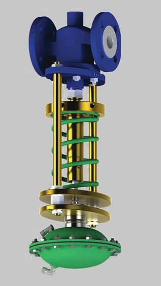
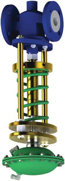
7 2.3 Design The Ballorex Delta DHC is installed either in the supply or the return line. The supply line pressure is received above the diaphragm and the return line pressure underneath the diaphragm. through capillary tubes. One capillary tube is to be connected to the drain of a partner valve like the Ballorex Venturi. Ballorex Vario. or Ballorex Basic. and the other capillary tube to a T-piece. When pressure increases in the system. it also increases above the Ballorex Delta DHC actuator diaphragm. This forces the valve cone downwards. and the valve gradually closes. As a result. a constant pressure drop is obtained across the circuit controlled by the Ballorex Delta DHC. The DN valves are single seated. whereas the DN valves are double seated. The medium pressure acts onto the bottom and top surfaces of the cone at the same time. In this way. the forces produced by the medium pressure on the cone are compensated the valve cone is pressure balanced. Without the actuator the valve is held in an open position by means of a spring. With force applied on the spindle the valve will close Capillary tube connection - Higher pressure diaphragm chamber - Diaphragm housing - Lower pressure diaphragm chamber - Spring - wheel - Spindle - Valve housing - Valve cone - Locking ring - Nut - Stud bolt - Gasket - Gasket for actuator - Disc - Spring - Valve seat 7
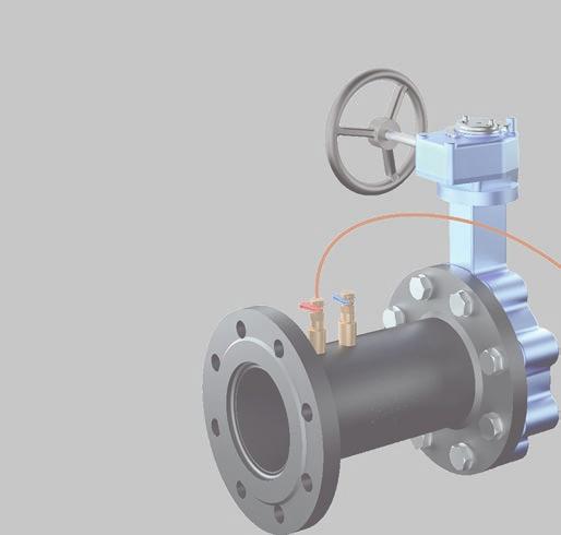
8 2. Introduction 2.4 Pressure balancing The Ballorex Delta DHC valve is provided with a selection of actuators for different pressure ranges. Depending on the actuator type the Ballorex Delta DHC is factory pre-set at: 50 - actuator for DN actuator for DN actuator for DN actuator for DN The Ballorex Delta DHC valve is set to a required differential pressure by means of the regulating wheel and a setting tool. By rotating the regulating wheel with a setting tool. any differential pressure. within the control range of each actuator. can be provided. 2.5 With partner valve The Ballorex Delta DHC can be used in combination with a Ballorex Venturi. a Ballorex Vario. or a Ballorex Basic. with drain. as a partner valve. In this case one capillary tube is connected to the coupling installed on the drain of the partner valve and the other to a T-piece in the system. Ballorex Delta DHC in combination with Ballorex Venturi as a partner valve. 8
9 The pre-setting of the differential pressure is done by rotating the regulating wheel in the Ballorex Delta DHC. The design is set on the Ballorex Venturi or Ballorex Vario using an Allen key. The Ballorex Delta DHC valve can be installed in the return line. The pressure loss across the Ballorex Venturi partner valve, installed in the supply line, is added to the pressure loss in the controlled circuit. When the Ballorex Venturi is installed in the supply line as a partner valve. it is always in the circuit controlled by the Ballorex Delta DHC. In this instance the pressure loss across the Ballorex Venturi is added to the pressure loss in the controlled circuit and needs to be taken into account when setting the Ballorex Delta DHC valve. The Ballorex Delta DHC can be installed in the supply line. The pressure loss across the Ballorex Venturi (partner valve) installed in the return line is not added to the pressure loss in the controlled circuit. When the Ballorex Venturi is installed in the return line and is used as a partner valve it is not in the circuit controlled by the Ballorex Delta DHC valve. Consequently the pressure loss is not taken into account when setting the Ballorex Delta DHC valve installed in the supply line. When the Ballorex Delta DHC valve is installed in combination with a Ballorex Vario or a Ballorex Basic. the pressure loss across the partner valve is not added to the pressure loss in the controlled circuit. provided that the capillary tube is connected to the drain on the outlet side of the partner valve. If the capillary tube is connected to the drain on the inlet side to the partner valve. the pressure loss must be taken into account when setting the Ballorex Delta DHC (see the application examples 5 and 6 for further details). 9
10 2. Introduction 2.6 Mounting An arrow on the Ballorex Delta DHC valve housing indicates the direction to be respected. The Ballorex Delta DHC can be installed in the return or the supply line. No straight piping before and after the Ballorex Delta DHC is required. The valve can be installed directly at bends. System flushing and pressure testing can be done when the maximum differential pressure setting is provided on the actuator. Maximum test pressure is 16 bar. It is extremely important that both sides of the rubber diaphragm in the actuator are filled with media before start up. If only media has been filled on the upper chamber the pressure can cause severe damage to the diaphragm. After mounting the capillary tubes, the diaphragm chamber has to be vented by loosening the connectors of the capillary tubes. When air is bled and water starts dripping from the capillary tubes, the connectors are tightened. The capillary tubes are to be connected in such a manner that the highest pressure (forward ) is always connected to the diaphragm side where the differential pressure adjustment is made (lower chamber). The lowest pressure (return) is always to be connected to the diaphragm side closest to the valve. To provide the required setting of the Ballorex Delta DHC, the pre-setting wheel is rotated using the setting tool. The differential pressure stabilized by the Ballorex Delta DHC can be verified with the Ballorex Balancing Computer BC2. After connecting one hose to the high pressure port on the Ballorex Venturi (if it is used as a partner valve) and the other hose to the drain valve (provided as an accessory and installed in a T-piece), the Ballorex Balancing Computer BC2 will display the pressure drop in the controlled part of the system. Differential pressure verification is also possible when the Ballorex Delta DHC is combined with the Ballorex Vario or the Ballorex Basic. It is recommended to install isolation valves to be able to service the controlled circuit. During the start-up isolation valves are opened simultaneously slowly and carefully in order to put pressure on both sides of the diaphragm. It is very important to not only put pressure on one side at a time because this will destroy the diaphragm. The differential pressure across the diaphragm must never exceed the set point pressure. 10
11 2.7 Operation The Ballorex Delta DHC valve is designed for district heating and district cooling systems to ensure a constant differential pressure across the motorized valve controlling through the heat exchanger or in a direct heating system. The stabilization of the differential pressure across the motorized valve improves the temperature control function. The motorized valve opens or closes only in response to the temperature signal from the controlled system and not because of the pressure fluctuation that would trigger changes. The Ballorex Delta DHC provides a constant differential pressure across a motorized valve at a heat exchanger. When the Ballorex Delta DHC is combined with a Ballorex Venturi or a Ballorex Vario. the solution can be used as both a constant pressure regulator and as a maximum limiter. This guarantees that the designed is never exceeded and that the motorized valve is operating with the required authority to provide optimal temperature control. The Ballorex Delta DHC provides a constant differential pressure across a motorized valve in a direct heating system. The Ballorex Delta DHC can be also combined with the Ballorex Basic to ensure constant differential pressure across the motorized valve and to be able to service the controlled part of the system or circuit. The Ballorex Basic can be used for verification provided that the pressure loss across the measuring points of this valve is at least 3.0. When the motorized valve is in a fully open position and the pressure loss across the measuring points of the Ballorex Basic is at least 3.0. the designed can be adjusted by providing the required differential pressure setting on the Ballorex Delta DHC. The motorized valve needs to be correctly sized for this application to operate with the desired authority. 11
12 3. Applications Application 1 - Temperature control in a heating system with air handling units The Ballorex Delta DHC installed at a heat exchanger in a central heating system will stabilize the differential pressure across the motorized valve. As a result the motorized valve only reacts to the temperature signal and not to pressure fluctuations. The Ballorex Venturi is used as a partner valve to connect the capillary tube and to limit the maximum. The pressure loss across the Ballorex Venturi needs to be taken into account when setting the Ballorex Delta DHC. Application 2 - Temperature control in an air-condition cooling system The Ballorex Delta DHC installed directly in a cooling system will stabilize the differential pressure. By providing stable working conditions the motorized valve only reacts to the temperature signal and not to pressure fluctuations. The Ballorex Venturi is used as a partner valve to connect the capillary tube and to limit the maximum. The pressure loss across the Ballorex Venturi needs to be taken into account when setting the Ballorex Delta DHC. 12
13 Application 3 - Temperature control in a domestic water system The Ballorex Delta DHC is installed on the primary side of a domestic water system. By stabilizing the differential pressure the desired working conditions for the motorized valve are ensured. The Ballorex Basic can be used as a partner valve to measure the. During commissioning the motorized valve is in a fully open position. When the pressure loss across the measuring points of the Ballorex Basic is at least 3.0, the designed can be verified and adjusted by providing the required differential pressure setting on the Ballorex Delta DHC valve. Application 4 - By-pass across a pump The Ballorex Delta DHC can be used in the pump by-pass (or across supply and return pipes of a circuit). This prevents the pump working against a dead head when all the sub-circuits are closed down. Note: For this application the Ballorex Delta DHC with reverse acting valve needs to be ordered. The valve is provided on request only! 13
14 3. Applications Application 5 - Ballorex Delta DHC in combination with Ballorex Vario or Ballorex Basic When the Ballorex Vario or the Ballorex Basic is used as a partner valve to the Ballorex Delta DHC, the capillary tube must be connected to the drain installed in the P/T port on the outlet side of the valve. In this instance the pressure loss across the partner valve is not added to the pressure loss in the controlled circuit and thus the Ballorex Delta DHC setting must be equal to the differential pressure required for the controlled circuit only. ΔPdHc = ΔPc Application 6 - Ballorex Delta DHC in combination with Ballorex Vario or Ballorex Basic When the Ballorex Vario or the Ballorex Basic is used as a partner valve to the Ballorex Delta DHC, the capillary tube must be connected to the drain installed in the P/T port on the inlet side of the valve. In this instance the pressure loss across the partner valve is added to the pressure loss in the controlled circuit and the Ballorex Delta DHC setting must be equal to the differential pressure required for the controlled circuit and the pressure loss across the partner valve. ΔPdHc = ΔPc + ΔPbv 14
15 4. Product data sheet 4.1 Product finder Ballorex Delta DHC DN Ballorex Delta DHC DN 150 DN 125 DN 100 DN 80 DN 65 DN 50 DN 40 DN 32 DN 25 DN 20 DN ,080 Flow rate m 3 /h 15
16 4. Product data sheet Ballorex Delta DHC DN with partner valve Ballorex Venturi as a partner valve to Ballorex Delta DHC DN 50 H DN 40 H DN 25 H & DN 32 H DN 20 H & DN 25 S DN 15 H DN 20 S DN 15 S & DN 20 L DN 15 L DN 15 UL Flow rate DN 300 DN 250 DN 200 DN 150 DN 125 DN 100 DN 80 DN ,080 Flow rate m 3 /h 16
17 Ballorex Vario as a partner valve to Ballorex Delta DHC DN 50 DN 40 DN 32 DN 25 DN DN Flow rate Ballorex Basic as a partner valve to Ballorex Delta DHC DN bar Pressure drop across valve - ΔPbasic DN 15 DN DN 25 DN 32 DN 40 DN Flow
18 4. Product data sheet Flow range Dimension Differential pressures setting range DN DN 20 DN DN 25 DN DN DN 40 DN DN 50 DN
19 Flow range Dimension Differential pressures setting range DN DN DN DN DN Differential pressure setting range [] Factory setting []
 Differential pressure setting range 20-80, 50-150, 100-250, 200-500 Leakage rate Less than 0.")
20 4. Product data sheet 4.2 Ballorex Delta DHC DN Dimensions Specifications temperature 120 C at 16 bar, 150 C at 14 bar, 250 C at 13 bar temperature -20 C diff. pressure 1600 bar pressure 16 bar (PN25 on request) Differential pressure setting range 20-80, , , Leakage rate Less than 0.05% of Kvs Marking on valve DN, PN, arrow, Kvs, differential pressure setting range, material Connection Flange EN PN16 Valve housing Cast iron EN-GJS Seat, cone and spindle Stainless steel Spring W. Nr powder coated Nuts and bolts 24 CrMo 4/A4 Stag bolt, set point adjuster and spindle housing St. 42, electroplated Diaphragm housing Steel Diaphragm EPDM O-rings EPDM DN A (mm) B (mm) C (mm) D (diameter) (mm) DN DN DN DN DN DN DN DN DN DN DN
21 Valve Article Dimension Nom. Inch DN 15 DN 20 DN 25 DN 32 DN 40 DN 50 Kvs m 3 /h DN 15 ½ ΔP Range [] DN 15 ½ DN 15 ½ DN 15 ½ DN 20 ¾ DN 20 ¾ DN 20 ¾ DN 20 ¾ DN DN DN DN DN 32 1¼ DN 32 1¼ DN 32 1¼ DN 32 1¼ DN 40 1½ DN 40 1½ DN 40 1½ DN 40 1½ DN DN DN DN
22 4. Product data sheet Valve Article Dimension Nom. Inch DN 65 DN 80 DN 100 DN 125 DN 150 Kvs m 3 /h DN 65 2½ ΔP Range [] DN 65 2½ DN 65 2½ DN 65 2½ DN DN DN DN DN DN DN DN DN DN DN DN DN DN DN DN
23 4.3 Flow diagrams The graphs are used to determine the total pressure loss across the Ballorex Delta DHC at the required. DN 15 - flange/flange bar Pressure drop across valve - ΔPdelta dhc Flow
24 4. Product data sheet DN 20 - flange/flange bar Pressure drop across valve - ΔPdelta dhc Flow
25 DN 25 - flange/flange bar Pressure drop across valve - ΔPdelta dhc Flow
26 4. Product data sheet DN 32 - flange/flange bar Pressure drop across valve - ΔPdelta dhc Flow
27 DN 40 - flange/flange bar Pressure drop across valve - ΔPdelta dhc Flow
28 4. Product data sheet DN 50 - flange/flange bar Pressure drop across valve - ΔPdelta dhc Flow
29 DN 65 - flange/flange bar Pressure drop across valve - ΔPdelta dhc Flow
30 4. Product data sheet DN 80 - flange/flange bar Pressure drop across valve - ΔPdelta dhc Flow
31 DN flange/flange bar Pressure drop across valve - ΔPdelta dhc Flow
32 4. Product data sheet DN flange/flange bar Pressure drop across valve - ΔPdelta dhc Flow
33 DN flange/flange bar Pressure drop across valve - ΔPdelta dhc Flow m 3 /h 33
34 4. Product data sheet 4.4 Valve sizing The available ranges in reference to the required differential pressure setting on the Ballorex Delta DHC valve are specified in the tables. DN 15 - flange/flange
35 The Ballorex Delta DHC DN 15 can be combined with the Ballorex Venturi DN as well as the Ballorex Vario DN or the Ballorex Basic DN to provide a constant differential pressure in the controlled part of the system. The Ballorex Venturi and the Ballorex Vario combined with the Ballorex Delta DHC also provide the option of limiting the maximum. See the application examples for further details. Partner valve Flow range Dimension Description DN 15UL Ballorex Venturi with drain For graphs consult chapter Ballorex Venturi DN 15L DN 15S DN 15H DN 20L DN 20S DN 20H DN 25S DN 25H DN 32H DN 40H DN 50H 35
36 4. Product data sheet Partner valve Flow range Dimension Description DN 15 Ballorex Vario with drain For graphs consult chapter Ballorex Vario DN DN DN DN DN 50 Partner valve Kvs Dimension Description m 3 /h 1.80* DN 15 Ballorex Basic with drain For graphs consult chapter Ballorex Basic. 4.65* DN * DN * DN * DN * DN 50 * For quick selection the Ballorex Basic range may be considered equal to the Ballorex Vario range. 36
37 DN 20 - flange/flange
38 4. Product data sheet The Ballorex Delta DHC DN 20 can be combined with the Ballorex Venturi DN as well as the Ballorex Vario DN or the Ballorex Basic DN to provide a constant differential pressure in the controlled part of the system. The Ballorex Venturi and the Ballorex Vario combined with the Ballorex Delta DHC also provide the option of limiting the maximum. See the application examples for further details. Partner valve Flow range Dimension Description DN 20L Ballorex Venturi with drain For graphs consult chapter Ballorex Venturi DN 20S DN 20H DN 25S DN 25H DN 32H DN 40H DN 50H DN 25H DN 32H DN 40H DN 50H Partner valve Flow range Dimension Description DN 65 Ballorex Venturi with drain (provided as an accessory) For graphs consult chapter Ballorex Venturi. 38
39 Partner valve Flow range Dimension Description DN 20 Ballorex Vario with drain For graphs consult chapter Ballorex Vario DN DN DN DN 50 Partner valve Kvs Dimension Description m 3 /h 4.65* DN 20 Ballorex Basic with drain For graphs consult chapter Ballorex Basic. 7.40* DN * DN * DN * DN 50 * For quick selection the Ballorex Basic range may be considered equal to the Ballorex Vario range. 39
40 4. Product data sheet DN 25 - flange/flange
41 The Ballorex Delta DHC DN 25 can be combined with the Ballorex Venturi DN as well as the Ballorex Vario DN or the Ballorex Basic DN to provide a constant differential pressure in the controlled part of the system. The Ballorex Venturi and the Ballorex Vario combined with the Ballorex Delta DHC also provide the option of limiting the maximum. See the application examples for further details. Partner valve Flow range Dimension Description DN 25S Ballorex Venturi with drain For graphs consult chapter Ballorex Venturi DN 25H DN 32H DN 40H DN 50H Partner valve Flow range Dimension Description DN 65 Ballorex Venturi with drain (provided as an accessory) For graphs consult chapter Ballorex Venturi. Partner valve Flow range Dimension Description DN 25 Ballorex Vario with drain For graphs consult chapter Ballorex Vario DN DN DN 50 41
42 4. Product data sheet Partner valve Kvs Dimension Description m 3 /h 7.40* DN 25 Ballorex Basic with drain For graphs consult chapter Ballorex Basic. 15.5* DN * DN * DN 50 * For quick selection the Ballorex Basic range may be considered equal to the Ballorex Vario range. 42
43 DN 32 - flange/flange


44 4. Product data sheet The Ballorex Delta DHC DN 32 can be combined with the Ballorex Venturi DN as well as the Ballorex Vario DN or the Ballorex Basic DN to provide a constant differential pressure in the controlled part of the system. The Ballorex Venturi and the Ballorex Vario combined with the Ballorex Delta DHC also provide the option of limiting the maximum. See the application examples for further details. Partner valve Flow range Dimension Description DN 32H Ballorex Venturi with drain For graphs consult chapter Ballorex Venturi DN 40H DN 50H Partner valve Flow range Dimension Description DN 65 DN 80 Ballorex Venturi with drain (provided as an accessory) For graphs consult chapter Ballorex Venturi. Partner valve Flow range Dimension Description DN 32 Ballorex Vario with drain For graphs consult chapter Ballorex Vario DN DN 50 Partner valve Kvs Dimension Description m 3 /h 15.5* DN 32 Ballorex Basic with drain For graphs consult chapter Ballorex Basic. 25.7* DN * DN 50 * For quick selection the Ballorex Basic range may be considered equal to the Ballorex Vario range. 44
45 DN 40 - flange/flange
46 4. Product data sheet The Ballorex Delta DHC DN 40 can be combined with the Ballorex Venturi DN as well as the Ballorex Vario DN or the Ballorex Basic DN to provide a constant differential pressure in the controlled part of the system. The Ballorex Venturi and the Ballorex Vario combined with the Ballorex Delta DHC also provide the option of limiting the maximum. See the application examples for further details. Partner valve Flow range Dimension Description DN 40H Ballorex Venturi with drain For graphs consult chapter Ballorex Venturi DN 50H Partner valve Flow range Dimension Description DN 65 DN 80 Ballorex Venturi with drain (provided as an accessory) For graphs consult chapter Ballorex Venturi DN 100 Partner valve Flow range Dimension Description DN 40 Ballorex Vario with drain For graphs consult chapter Ballorex Vario DN 50 Partner valve Kvs Dimension Description m 3 /h 25.7* DN 40 Ballorex Basic with drain For graphs consult chapter Ballorex Basic. 44.0* DN 50 * For quick selection the Ballorex Basic range may be considered equal to the Ballorex Vario range. 46
47 DN 50 - flange/flange
48 4. Product data sheet The Ballorex Delta DHC DN 50 can be combined with the Ballorex Venturi DN as well as the Ballorex Vario DN 50 or the Ballorex Basic DN 50 to provide a constant differential pressure in the controlled part of the system. The Ballorex Venturi and the Ballorex Vario combined with the Ballorex Delta DE also provide the option of limiting the maximum. See the application examples for further details. Partner valve Flow range Dimension Description DN 50H Ballorex Venturi with drain For graphs consult chapter Ballorex Venturi. Partner valve Flow range Dimension Description DN 65 DN 80 Ballorex Venturi with drain (provided as an accessory) For graphs consult chapter Ballorex Venturi DN 100 Partner valve Flow range Dimension Description DN 50 Ballorex Vario with drain For graphs consult chapter Ballorex Vario. Partner valve Kvs Dimension Description m 3 /h 44.0* DN 50 Ballorex Basic with drain For graphs consult chapter Ballorex Basic. * For quick selection the Ballorex Basic range may be considered equal to the Ballorex Vario range. 48
49 DN 65 - flange/flange
50 4. Product data sheet The Ballorex Delta DHC DN 65 can be combined with the Ballorex Venturi DN to provide a constant differential pressure in the controlled part of the system as well as to ensure the option of limiting the maximum. See the application examples for further details. Partner valve Flow range Dimension Description DN 65 DN 80 Ballorex Venturi with drain (provided as an accessory) For graphs consult chapter Ballorex Venturi DN DN
51 DN 80 - flange/flange
52 4. Product data sheet The Ballorex Delta DHC DN 80 can be combined with the Ballorex Venturi DN to provide a constant differential pressure in the controlled part of the system as well as to ensure the option of limiting the maximum. See the application examples for further details. Partner valve Flow range Dimension Description DN 80 DN 100 Ballorex Venturi with drain (provided as an accessory) For graphs consult chapter Ballorex Venturi DN DN
53 DN flange/flange
54 4. Product data sheet The Ballorex Delta DHC DN 100 can be combined with the Ballorex Venturi DN to provide a constant differential pressure in the controlled part of the system as well as to ensure the option of limiting the maximum. See the application examples for further details. Partner valve Flow range Dimension Description DN 100 DN 125 Ballorex Venturi with drain (provided as an accessory) For graphs consult chapter Ballorex Venturi DN DN
55 DN flange/flange
56 4. Product data sheet The Ballorex Delta DHC DN 125 can be combined with the Ballorex Venturi DN to provide a constant differential pressure in the controlled part of the system as well as to ensure the option of limiting the maximum. See the application examples for further details. Partner valve Flow range Dimension Description DN 125 DN 150 Ballorex Venturi with drain (provided as an accessory) For graphs consult chapter Ballorex Venturi DN DN
57 DN flange/flange
58 4. Product data sheet The Ballorex Delta DHC DN 150 can be combined with the Ballorex Venturi DN to provide a constant differential pressure in the controlled part of the system as well as to ensure the option of limiting the maximum. See the application examples for further details. Partner valve Flow range Dimension Description DN 150 DN 200 Ballorex Venturi with drain (provided as an accessory) For graphs consult chapter Ballorex Venturi DN DN

59 4.5 Valve setting DN The Ballorex Delta DHC valve is provided with four differential pressure setting ranges. The differential pressure setting is done turning a regulating wheel operated by a setting tool. Differential pressure setting range Factory setting Other settingsfactory setting To provide any other setting on the Ballorex Delta DHC valve, the regulating wheel must be rotated using a setting tool. The rotations of the regulating wheel change the spring compression and thus the force counteracting the force produced by the pressure in the membrane chamber. Each time the regulating wheel is rotated, a new force equilibrium is obtained ensuring the desired differential pressure in the controlled circuit. In order to control the setting, pressure gauges must be installed in the supply and the return lines. The differential pressure can be also checked with the Ballorex Balancing Computer BC2 provided that the medium temperature does not exceed 90 C. The balancing computer must be connected to the measuring point on a partner valve and to a measuring point installed in the pipe inside the controlled loop of the Ballorex Delta DHC valve. The Ballorex Delta DHC is provided with two capillary tubes for installation in the supply or the return line. The valve does not provide the shut-off function. It is therefore recommended to install isolation valves in the system. 59
60 5. Accessoires Accessories Article Dimension Description DN 15UL Ballorex Venturi with Combi Drain Midi DN 15L DN 15S DN 15H DN 20L DN 20S DN 20H DN 25S DN 25H DN 32H DN 40H DN 50H DN 15 Ballorex Vario with Combi Drain Midi DN DN DN DN DN 50 60


61 Accessories Article Dimension Description DN 15 Ballorex Basic with drain DN DN DN DN DN DN 65 DN 80 Ballorex Venturi - When used as a partner valve a Combi Drain Maxi for capillary tube connection is required. The drain is provided as an accessory to DN 100 be ordered separately DN DN DN DN DN R 1/4 connection 3/8 UNF measuring point G 3/4 drain Combi Drain Maxi - drain with measuring point for Ballorex Venturi DN The capillary tube from the Ballorex Delta DHC is connected to the R 1/4 coupling delivered along with the Combi Drain Maxi and installed on the drain R ¼ A coupling installed on the drain of the Ballorex Venturi, the Ballorex Vario or the Ballorex Basic DN to connect the capillary tube with R 1/4 connector from the Ballorex Delta DHC On request 1.0 m, Ø 4 mm Capillary tube with ¼ connector 61
Pressure Independent Control Valve
 Pressure Independent Control Valve www.ballorex.com Table of contents Chapter Ballorex Dynamic DN 15L-50H 1. Safety instructions 4 1.1 Rules/regulations 4 1.2 Intended use 5 1.3 Initial operation 5 1.4
Pressure Independent Control Valve
 Pressure Independent Control Valve www.ballorex.com Table of contents Chapter Ballorex Dynamic DN 15L-50H 1. Safety instructions 4 1.1 Rules/regulations 4 1.2 Intended use 5 1.3 Initial operation 5 1.4
Ballorex Venturi 3.1 Introduction
 3.1 Introduction Venturi Fixed Orifice Double Regulating Valve (FODRV) DN 15-600 1/2-24 Venturi description The Venturi is a range of manual balancing valves used in water-based heating and cooling systems
Description. Ballorex Venturi. Versions. Benefits. Robinets manuels Balancing
 Ballorex Venturi Description The Ballorex Venturi is a range of manual balancing valves used in water-based heating and cooling systems to ensure an evenly distributed flow in zones, branches, risers and
BROEN BALLOREX Dynamic R E ADY STEADY GO!
 BROEN BALLOREX Dynamic R E ADY STEADY GO! Perfect flow with dynamic balancing BROEN BALLOREX Dynamic is a combined pressure independent flow limiter and control valve. The new and innovative range of dynamic
DA 50. Differential pressure controllers Adjustable set-point
 DA 50 Differential pressure controllers Adjustable set-point IMI TA / Differential pressure controllers / DA 50 DA 50 These differential pressure controllers for heating and cooling systems are particularly
Automatic balancing valves ASV-PV DN (3rd gen.)
") Automatic balancing valves ASV-PV DN 50-100 (3rd gen.) Description / Application Partner valve ASV-PV DN 50 ASV-PV DN 65-100 MSV-F2 DN 50-100 ASV balancing valves are used for dynamic hydronic balance
Automatic balancing valves ASV-PV DN 50-100 (3rd gen.) Description / Application Partner valve ASV-PV DN 50 ASV-PV DN 65-100 MSV-F2 DN 50-100 ASV balancing valves are used for dynamic hydronic balance
k VS DN (mm) Connections ( C) (m 3 /h)
 Connections ( C) (m 3 /h)") Data sheet Differential pressure and flow controller (PN 16, 25, 40) AFPQ / VFQ 2( - return mounting, adjustable setting AFPQ 4 / VFQ 2( - flow mounting, adjustable setting Description The controller has
Data sheet Differential pressure and flow controller (PN 16, 25, 40) AFPQ / VFQ 2( - return mounting, adjustable setting AFPQ 4 / VFQ 2( - flow mounting, adjustable setting Description The controller has
Differential pressure controller (PN 16, 25, 40) AFP(-9) / VFG 2(1) return and flow mounting, adjustable setting
 AFP(-9) / VFG 2(1) return and flow mounting, adjustable setting") Data sheet Differential pressure controller (PN 16, 25, 40) AFP(-9) / VFG 2(1) return and flow mounting, adjustable setting Description The controller has a control valve, an actuator with one control
Data sheet Differential pressure controller (PN 16, 25, 40) AFP(-9) / VFG 2(1) return and flow mounting, adjustable setting Description The controller has a control valve, an actuator with one control
Technote. Frese YDF-2F & YDF-20F - differential pressure control valve. Application. Benefits. Features.
 Page 1 of 5 Application Frese YDF-2F and YDF-20F differential pressure control valves are used in central heating-, ventilation-, and district heating systems This model is a high-performing adjustable
Flow controller with integrated control valve (PN 16) AHQM return and flow mounting
 AHQM return and flow mounting") Data sheet Flow controller with integrated control valve (PN 16) AHQM return and flow mounting Description DN 15-32 DN 40, 50 DN 50-100 DN 125 DN 150 DN 200, 250 AHQM is a self-acting flow controller with
Data sheet Flow controller with integrated control valve (PN 16) AHQM return and flow mounting Description DN 15-32 DN 40, 50 DN 50-100 DN 125 DN 150 DN 200, 250 AHQM is a self-acting flow controller with
Static Balancing Valve
 Static Balancing Valve Series W-JP45X-16Q Sizes: DN50-DN300 APPLICATION The Series W-JP45X Static Balancing Valve is designed for flow balancing in cooling, heating or process water systems. Its measuring
EN Operating manual. Motorised zone valve. Three-way, 22 mm & 28 mm 3PV2, 3PV8 & VRMH3
 EN Operating manual Motorised zone valve Three-way, 22 mm & 28 mm 3PV2, 3PV8 & VRMH3 This manual ensures safe and efficient use of the 3PV2 or 3PV8 force-actuated three-way valve with spring-loaded return
Flow-compensated temperature controller AVTQ DN 15
 Data sheet Flow-compensated temperature controller AVTQ DN 15 Description AVTQ is a self-acting flow-compensated temperature controller primarily for use in district heating systems with plate heat exchangers
Flow controller with integrated control valve (PN 16) AHQM - return and flow mounting
 AHQM - return and flow mounting") Flow controller with integrated control valve (PN 16) AHQM - return and flow mounting Description Controllers are used together with Danfoss electrical actuators: DN 15-32 with - AMV(E) 10 - AMV(E) 13
Flow controller with integrated control valve (PN 16) AHQM - return and flow mounting Description Controllers are used together with Danfoss electrical actuators: DN 15-32 with - AMV(E) 10 - AMV(E) 13
Product Sheet Pre-Fabricated Flushing Bypass Assembly for Plant Applications Hero Plant DN15-150
 Product Sheet Pre-Fabricated Flushing Bypass Assembly for Plant Applications Hero Plant DN15-150 Description Hero Plant is a pre-fabricated, flushing bypass arrangement for balance, control, isolation,
Combi valves PN 16 with flanged connections
 4 315 ACVATIX Combi valves PN 16 with flanged connections Pressure Independent Combi Valves VPF43.. With integrated pressure differential controller Valve body made of gray cast iron GJL-250 DN 50, DN
Flow controller (PN 25) AVQ - return and flow mounting
 AVQ - return and flow mounting") Data sheet Flow controller (PN 5) - return and flow mounting Description is a self-acting flow controller primarily for use in district heating systems. The controller closes when set max. flow is exceeded.
Data sheet Flow controller (PN 5) - return and flow mounting Description is a self-acting flow controller primarily for use in district heating systems. The controller closes when set max. flow is exceeded.
Product Catalog. Precision Control DeltaPValves. guaranteed delta T 10-year warranty made in the USA
 Product Catalog Precision Control DeltaPValves guaranteed delta T www.flowcontrol.com 10-year warranty www.flowcontrol.com made in the USA P.O. Box 848 18715 141st Ave NE Woodinville, Washington 98072
Storage, operating and maintenance instructions for AZ plug valves and Standard valves
 ARMATUREN Plug - Valves metallic with PTFE Sleeve 2-7 way Storage, operating and maintenance instructions for AZ plug valves and Standard valves Plug - Valves FEP/PFA - lined, 2-3 way Butterfly - Valves
ZONE CONTROLE / 2-WAY
 ZONE CONTROLE / 2-WAY PRESSURE INDEPENDENT BALANCING AND CONTROL VALVE ON/OFF High-performing and compact, these pressure-independent temperature control valves for variable flow heating and cooling systems,
Operating Instructions
 Operating Instructions BE2700 Brinkmann Immersions pumps of the series TA/STA/TAL/SAL901... 1303 Contents 1 General...1 2 Safety...2 3 Transport and storage...2 4 Description of product and accessories...2
We proudly deliver a unique and
 Linear 3-Way Control Valve PN 10/16/25, DN15 - DN300 BENEFITS Nominal pressure PN 16 Almost linear Two balance single seats kvs Regulating capability > 25 kvr Leakage 0.05% of kvs For regulating of process
Ballorex Vario. Description. Versions. Benefits. Applications. Balancing
 Ballorex Vario Description Ballorex Vario is a variable orifice double regulating valve for balancing water-based heating and cooling systems. The balancing performed ensures the required distribution
HS10S-FA. Water station. Product specification sheet
 HS10S-FA Water station Product specification sheet Range of Application Medium Drinking water Inlet pressure Max. 16 bar Outlet pressure 1.5-6.5 bar Installation position Horizontal with filter bowl downwards
Installation and Operation Instructions. VAG ROTOP Portable Electric Drive
 Installation and Operation Instructions VAG ROTOP Portable Electric Drive KAT-B 5551 Edition 1-01/2018 Content 1 General 3 1.1 Safety 3 1.2 Proper use 3 2 Transport and Storage 3 2.1 Transport 3 2.2 Storage
Butterfly valves PN 16
 s 4 119 ACVATIX TM Butterfly valves PN 16 VKF42.. Gray cast iron or nodular cast iron valve body DN 50...600 k vs 65...37,000 m 3 /h For fitting with PN 16 counter-flanges to ISO 7005 Tight-closing in
2 PIECES BALL VALVE PN63
 2 PIECES BALL VALVE PN63 Model/Ref: 220 www.lauridsenindustri.com Size : Ends : Min Temperature : Max Temperature : DN 15 to DN 400 Flanges ISO PN10/16-10 C + 120 C Max Pressure : 16 Bars up to DN 200
HS10S-FA. Water station. Product specification sheet
 HS10S-FA Water station Product specification sheet Range of Application Medium Drinking water Inlet pressure Max. 16 bar Outlet pressure 1.5-6.5 bar Installation position Horizontal with filter bowl downwards
Flow controller (PN 25) AVQ - return and flow mounting
 AVQ - return and flow mounting") Data sheet Flow controller (PN 5) - return and flow mounting Description is a self-acting flow controller primarily for use in district heating systems. The controller closes when set max. flow is exceeded.
Data sheet Flow controller (PN 5) - return and flow mounting Description is a self-acting flow controller primarily for use in district heating systems. The controller closes when set max. flow is exceeded.
Connection. k VS value m 3 /h
 76.122/1 VUP: Pressure-relieved through flanged valve, PN 25 How energy efficiency is improved Thanks to the pressure compensation, savings can be made with the actuator. Precision and reliability go without
Mounting and Operating Instructions EB 5894 EN. Electric control valves with jet pump. Flanged version of valve with jet pump
 Electric control valves with jet pump Type 3267/5824, Type 3267/5825, Type 3267/3374, Type 3267/3274 Pneumatic control valves with jet pump Type 3267-1, Type 3267-7 Flanged version of valve with jet pump
Pressure independent balancing and control valve AB-QM DN
 Data sheet Pressure independent balancing and control valve AB-QM DN 10-250 The AB-QM valve equipped with an actuator is a control valve with full authority and an automatic balancing function / flow limitation.
AVQMT. AVQT controller can be combined with AVT or STM thermostatic actuators.
 Data sheet Flow and temperature controller with / without integrated control valve (PN 25) AVQT - flow and temperature controller AVQMT - flow and temperature controller with integrated control valve Description
Technical Principles of Valves
 Technical Principles of Valves Symbols and Circuit Functions Symbol to DIN-ISO 1219 The circuit function illustrations are defined to the DIN-ISO 1219 Standard. These can be used to show other switching
Data sheet Pressure independent control valve with integrated flow limiter AVQM (PN 16) - return and flow mounting
 - return and flow mounting") Pressure independent control valve with integrated flow limiter AVQM (PN 16) - return and flow mounting Description Controllers are used together with Danfoss electrical actuators: - AMV 150 1) - AMV(E)
Pressure independent control valve with integrated flow limiter AVQM (PN 16) - return and flow mounting Description Controllers are used together with Danfoss electrical actuators: - AMV 150 1) - AMV(E)
TECHNICAL DATA CAUTION
 Page 1 of 6 1. DESCRIPTION The Viking Model D-2 Accelerator is a quick-opening device, with an integral anti-flood assembly, used to increase the operating speed of a differential type dry pipe valve.
Pressure independent balancing and control valve For ON/OFF control
 KT 512 Pressure independent balancing and control valve For ON/OFF control Pressurisation & Water Quality Balancing & Control Thermostatic Control ENGINEERING ADVANTAGE High-performing and compact, these
Flow controller (PN 16, 25, 40) AFQ / VFQ 2(1) - return and flow mounting
 AFQ / VFQ 2(1) - return and flow mounting") Data sheet Flow controller (PN 16, 5, 40) AFQ / VFQ ( - return and flow mounting Description The controller has a control valve with adjustable flow restrictor and an actuator with one control diaphragm.
Data sheet Flow controller (PN 16, 5, 40) AFQ / VFQ ( - return and flow mounting Description The controller has a control valve with adjustable flow restrictor and an actuator with one control diaphragm.
PRESSURE REDUCING CONTROL VALVE
 PRESSURE REDUCING CONTROL VALVE 06/08 Schematics Throttles to reduce high upstream pressure to constant lower downstream pressure Reducing setpoint is adjustable 2 (AOS) X P/L Standard Components 1 Main
DN [ ] DN [ ] Functional data Media Cold and hot water, water with glycol up to max. 50% vol.
![DN [ ] DN [ ] Functional data Media Cold and hot water, water with glycol up to max. 50% vol.](/thumbs/90/102027903.jpg "DN [ ] DN [ ] Functional data Media Cold and hot water, water with glycol up to max. 50% vol.") Technical data sheet R6..W..-S8 Characterised control valves, -way, with PN 16 flange For closed cold and hot water systems For modulating water-side control of air purification and heating systems Air
Technical data sheet R6..W..-S8 Characterised control valves, -way, with PN 16 flange For closed cold and hot water systems For modulating water-side control of air purification and heating systems Air
TA-PILOT-R. Differential pressure controllers Pilot operated differential pressure controller with adjustable set-point
 TA-PILOT-R Differential pressure controllers Pilot operated differential pressure controller with adjustable set-point IMI TA / Differential pressure controllers / TA-PILOT-R TA-PILOT-R The TA-PILOT-R
Pressure independent balancing and control valve AB-QM DN
 Pressure independent balancing and control valve AB-QM DN 10-150 AB-QM valve equipped with an actuator is a control valve with full authority and automatic balancing function - flow limiter. Typical applications
Differential pressure relief controller (PN 16, 25, 40) AFPA / VFG 2(1)
 AFPA / VFG 2(1)") Data sheet Differential pressure relief controller (, 25, 40) AFPA / VFG 2() Description The controller has a control valve, an actuator with one control diaphragm and spring for differential pressure
Data sheet Differential pressure relief controller (, 25, 40) AFPA / VFG 2() Description The controller has a control valve, an actuator with one control diaphragm and spring for differential pressure
Type Operating Instructions. Bedienungsanleitung Manuel d utilisation. 2/2-Way Solenoid Valve 2/2-Wege-Magnetventil Électrovanne à 2/2 voies
 Type 5282 2/2-Way Solenoid Valve 2/2-Wege-Magnetventil Électrovanne à 2/2 voies Operating Instructions Bedienungsanleitung Manuel d utilisation 1 OPERATING INSTRUCTIONS The operating instructions contain
Combined automatic balancing valve AB-PM valve DN 15-25, PN 16
 Data sheet Combined automatic balancing valve AB-PM valve DN 15-25, PN 16 Description AB-PM is a combined automatic balancing valve. It features three function in compact valve body: 1. Differential pressure
Pressure Independent Control Valve Applications for Building Automation, Temperature Controls, and HVAC Two-Way Chilled Water Hot Water
 Rev: 08/19/2013 (ATiMX) Features Pressure Independent Control Valve Applications for Building Automation, Temperature Controls, and HVAC Two-Way Chilled Water Hot Water The Auto Touch Independent Max (ATiMX)
Type Operating Instructions. Bedienungsanleitung Manuel d utilisation. 2/2-Way Solenoid Valve 2/2-Wege-Magnetventil Électrovanne à 2/2 voies
 Type 5282 2/2-Way Solenoid Valve 2/2-Wege-Magnetventil Électrovanne à 2/2 voies Operating Instructions Bedienungsanleitung Manuel d utilisation Contents 1 Operating Instructions... 2 2 Authorized use...
Pressure relief valve
 Pressure relief valve Operating manual Series DHV 712 Version BA-2015.10.20 EN Print-No. 300 510 TR MA DE Rev001 ASV Stübbe GmbH & Co. KG Hollwieser Straße 5 32602 Vlotho Germany Phone: +49 (0) 5733-799-0
700 LARGE SIZE SERIES
 700 LARGE SIZE SERIES ENGINEERING DATA CONTENT BERMAD 700 Large Size Series 2 Model: 700-M5, 700-M6, 700-M5L 2 Features and Options 2 Technical Data 3 Valve PlugswCharacteristics 3 Valve Travel 3 Flow
Pre-Fabricated Flushing Bypass Assembly for Plant Applications Hero Plant DN15-150
 Pre-Fabricated Flushing Bypass Assembly for Plant Applications Description Hero Plant is a pre-fabricated, flushing bypass arrangement for balance, control, isolation, and operation of plant devices. Flow
Pressure independent balancing and control valve
 Pressure independent balancing and control valve AB-QM DN 10-150 AB-QM valve equipped with an actuator is a control valve with full authority and automatic balancing function - flow limiter. Typical applications
Technote. Frese OPTIMA Compact DN10-DN50 - pressure independent balancing & control valve. Application. Features. Benefits.
 Page of 5 Frese OPTIMA Compact DN-DN5 Application Frese OPTIMA Compact pressure independent balancing & control valve (PIBCV) is used in heating and cooling systems in applications with Fan Coil Units,
Overview of types. Characterised control valves, 3-way, with internal thread For closed cold and warm water systems
 Technical data sheet R3..xx-S.. Characterised control valves, 3-way, with internal thread For closed cold and warm water systems For modulating water-side control of HU and heating systems ir bubble-tight
Flow controller with integrated control valve (PN 16) AVQM - return and flow mounting
 AVQM - return and flow mounting") Data sheet Flow controller with integrated control valve (PN 16) AVQM - return and flow mounting Description The controller has a control valve with adjustable flow restrictor, connection neck for electrical
Data sheet Flow controller with integrated control valve (PN 16) AVQM - return and flow mounting Description The controller has a control valve with adjustable flow restrictor, connection neck for electrical
HERZ-Connect 4 / Compact Connect 4 & Commissioning Centres
 www.herz.eu HERZ-Connect 4 / Compact Connect 4 & Commissioning Centres Simple and cost efficient methodes of thermal units control 1 Connect 4.indd 1 17.11.2015 10:31:20 HERZ- Connect 4 HERZ Connect-4
General Information Hydrants and Flushing Valves
 General Information Hydrants and Flushing Valves Product Categories 4.1 Underground Hydrants 4-4 4.2 Above Gound Hydrants 4-10 4.3 Flushing Valves 4-13 www.hawle.de 4-3 4.1 Underground Hydrants www.hawle.de
Pressure independent combined control and balancing valves with independent EQM characteristics
 Combined control & balancing valves TA-FUS1ON-P Pressure independent combined control and balancing valves with independent EQM characteristics Pressurisation & Water Quality Balancing & Control Thermostatic
Installation and operating manual
 LK product no: 901002 and 901102 501002 and 501102 (JIS) Article no: 74500 Revision: 9 Article no: 74500 Revision: 9 2 (23) Contents 1. General information... 5 2. Safety precautions... 5 2.1 Significance
Mustang Series PRESSURE REDUCING CONTROL VALVE. M115 (Globe) M1115 (Angle) Schematic. Standard Components. Options & Accessories.
 M1115 (Angle) Schematic. Standard Components. Options & Accessories.") PRESSURE REDUCING CONTROL VALVE 02/09 Schematic Throttles to reduce high upstream pressure to constant lower downstream pressure Reducing setpoint is adjustable 2 (AOS) P/L Standard Components 1 Main Valve
PRESSURE REDUCING CONTROL VALVE 02/09 Schematic Throttles to reduce high upstream pressure to constant lower downstream pressure Reducing setpoint is adjustable 2 (AOS) P/L Standard Components 1 Main Valve
Mounting and Operating Instructions EB 5868/5869 EN
 Electric Control Valves Types 3213/5857, 3213/5824, Types 3214/5824, 3214/3374, 3214/3274 with safety function: Types 3213/5825, 3214/5825, 3214/3374, 3214/3274 Pneumatic Control Valves Types 3213/2780-1,
Materials : Cast iron body EN GJL-250
 Certificate 3.1 Size : Ends : Min Temperature : Max Temperature : DN 15 to DN 600 Flanges R.F. PN10/16-10 C + 120 C Max Pressure : 16 Bars up to DN 200 ( 10 bars over ) Specifications : Removable stainless
ATi Max Series. Pressure Independent Control Valves 2 Way 2-1/2-6
 The Auto Touch Independent Max (ATiMX) valve brings pressure independent control technology to valves up to 6 and flow rates up to 468 GPM. It is a state-of-the-art control valve combining a high quality/
Installation and operating manual Quick closing valve (Bellow sealed) LK product no:
 LK product no:") LK product no: 902002 Article no: 74506 Revision: 2 Contents 1. General information... 3 2. Safety precautions... 3 2.1 Significance of symbols... 3 2.2 Explanatory notes on safety information... 3 3.
LK product no: 902002 Article no: 74506 Revision: 2 Contents 1. General information... 3 2. Safety precautions... 3 2.1 Significance of symbols... 3 2.2 Explanatory notes on safety information... 3 3.
V9000 PICV Pressure Independent Control Valve
 V9000 Series Valve Body V9000 PICV Pressure Independent Control Valve Wireless Pneumatic Floating FLP Thermostatic Thermoelectric Modulating 0/2-10Vdc FLP Modulating 0-5Vdc/5-10Vdc FLP Pulse Width Modulating
ROTARY MOTORIZED VALVES ROTARY MOTORIZED VALVES
 ROTARY MOTORIZED VALVES 19 CONTENTS ROTARY MOTORIZED VALVES INTRODUCTION AND SELECTION GUIDES Series VRG130 DN 15 50, Kvs 0.4 40, PN10 33 34 35 Series VRG140 DN 15 50, Kvs.5 40, PN10 CHANGE-OVER/DIVERTING
Mounting and Operating Instructions EB 8111/8112 EN. Valve Series V2001 Globe Valve Type 3321
 Valve Series V2001 Globe Valve Type 3321 Fig. 1 Type 3321 Valve with mounted rod-type yoke for pneumatic or electric actuators (partial view) Mounting and Operating Instructions EB 8111/8112 EN Edition
2- and 3-port valves with flanged connections, PN 16
 4 404 VXF43.. ACVATIX 2- and 3-port valves with flanged connections, PN 16 From the large-stroke valve line VXF43.. High-performance valves for medium temperatures from -20 220 C Valve body of nodular
DELUGE VALVE MODEL: SD-DVA TECHNICAL DATA : VALVE OPERATION TRIM DESCRIPTION DESCRIPTION PRESSURE THREADED OPENING
 DELUGE VALVE MODEL: SD-DVA TECHNICAL DATA : NOMINAL SIZE MATERIAL MAXIMUM SERVICE PRESSURE 200, 150, 100, 80 & 50NB Cast Iron 12 Bar (175 PSI) THREADED OPENING MOUNTING FACTORY HYDROSTATIC TEST PRESSURE
2-Port Seat Valves with Flange, PN 25
 OEM 2-Port Seat Valves with Flange, PN 25 VVF52...E Spheroidal cast iron EN-GJS-400-8-LT valve body DN 5...40 k vs 0.63 25 m 3 /h Can be equipped with SQX E- motoric or SKD E- or SKB - electrohydraulic
2-Port and 3-Port Zone Valves PN 16
 4 842 2-port valves VVI4615 to VVI4625 3-port valves VXI4615 to VXI4625 2-port valves VVS4615 to VVS4625 3-port valves VXS4615 to VXS4625 2-Port and 3-Port Zone Valves PN 16 VVI46 VXI46 VVS46 VXS46 Hot-pressed
2- and 3-port valves with flanged connections, PN 16
 4 404 VVF43.. VVF43..K VXF43.. ACVATIX 2- and 3-port valves with flanged connections, PN 16 From the large-stroke valve line VVF43.. VXF43.. High-performance valves for medium temperatures from -20 220
PRESSURE REDUCING VALVE
 Schematic Throttles to reduce high upstream pressure to constant lower downstream pressure Low Flow By-Pass controls at low flows 4 PRESSURE REDUCING VALVE with LOW-FLOW BY-PASS FEATURE Main Line valve
PRESSURE REDUCING VALVE
 Schematic Throttles to reduce high upstream pressure to constant lower downstream pressure Low Flow By-Pass controls at low flows 4 PRESSURE REDUCING VALVE with LOW-FLOW BY-PASS FEATURE Main Line valve
GL Ludemann Y-Strainers
 GL Ludemann Y-Strainers Installation, Operation and Maintenance Manual English Issue 1-03/2014 - Page 1/7 GENERAL These instructions are for installing, operation and maintenance of Y-strainers fabricated
Butterfly valves PN 16
 s 4 119 ACVATIX TM Butterfly valves PN 16 VKF42.. Gray cast iron or nodular cast iron valve body DN 50...600 k vs 65...37,000 m 3 /h For fitting with PN 16 counter-flanges to ISO 7005 Tight-closing in
PRESSURE REDUCING VALVE
 Schematic Throttles to reduce high upstream pressure to constant lower downstream pressure Closes quickly when downstream pressure exceeds reduced pressure setpoint 3 PRESSURE REDUCING VALVE with SURGE
Pressure relief controller AFA / VFG 2(1) (PN 16, 25, 40)
 (PN 16, 25, 40)") Data sheet Pressure relief controller AFA / VFG 2(1) (PN 16, 25, 40) Description The controller is a self-acting pressure relief controller primarily for use in district heating systems. The controller
Data sheet Pressure relief controller AFA / VFG 2(1) (PN 16, 25, 40) Description The controller is a self-acting pressure relief controller primarily for use in district heating systems. The controller
ROTARY MOTORIZED VALVES ROTARY MOTORIZED VALVES
 ROTARY MOTORIZED VALVES 5 6 ESBE ROTARY VALVES AND ACTUATORS regulate the heating comfort of millions of households. Our offer is a wide range of rotary valves in a number of different designs for the
MADE OF STAINLESS...
 MADE OF STAINLESS... Size : Ends : Min Temperature : Max Temperature : DN 15 to DN 200 Flanged R.F. PN25/40-29 C + 425 C Max Pressure : 40 Bars Specifications : Stainless steel removable filter Bolted
STRÖMAX-MFS Circuit Control Valve with Measuring Valves Inclined Model
 Circuit Control Valve with Measuring Valves Inclined Model Standard Sheet for 4218 MFS Edition 0700 (1299) A H L 4218 Order Number DN L H A Ø Weight kg 1 4218 06 50 230 250 166 15 1 4218 07 65 290 278
STAF, STAF-SG. Balancing valves PN 16 and PN 25 DN
 STAF, STAF-SG Balancing valves PN 16 and PN 25 DN 20-400 IMI TA / Balancing valves / STAF, STAF-SG STAF, STAF-SG A flanged, cast iron (STAF) and ductile iron (STAF-SG) balancing valve that delivers accurate
Differential pressure controller with flow limitation and with integrated control valve (PN 16) AHPBM-F flow mounting, fixed setting
 AHPBM-F flow mounting, fixed setting") Data sheet Differential pressure controller with flow limitation and with integrated control valve (PN 16) AHPBM-F flow mounting, fixed setting Description The controller has a control valve with adjustable
Data sheet Differential pressure controller with flow limitation and with integrated control valve (PN 16) AHPBM-F flow mounting, fixed setting Description The controller has a control valve with adjustable
Mounting and operating instructions EB EN. Differential Pressure and Temperature Regulator with Flow Limiter Type 2479/2430 K
 Differential Pressure and Temperature Regulator with Flow Limiter Type 2479/2430 K Special version DN 15 with differential pressure set point p = 0.5 bar Fig. 1 Type 2479/2430 K Mounting and operating
BQE: 3-way flanged valve, PN 16
 Ambient conditions 1) Operating temperature 2) -10...150 C Product data sheet 56.118 BQE: 3-way flanged valve, PN 16 How energy efficiency is improved Efficient use in continuous control systems Features
Balancing Valves. Venturi Commissioning Valve (FODRV) & (DRV) Cu x Cu Compression DN10-DN50. BOSS TM 901SC Venturi DRV DN
 & (DRV) Cu x Cu Compression DN10-DN50. BOSS TM 901SC Venturi DRV DN") Venturi Commissioning Valve (FODRV) & (DRV) Cu x Cu Compression DN-DN Balancing Valves BOSS TM 900SC Venturi FODRV DN1- BOSS TM 901SC Venturi DRV DN1- Specification The commissioning station and DRV incorporates
Venturi Commissioning Valve (FODRV) & (DRV) Cu x Cu Compression DN-DN Balancing Valves BOSS TM 900SC Venturi FODRV DN1- BOSS TM 901SC Venturi DRV DN1- Specification The commissioning station and DRV incorporates
Operating Instructions Garlock Butterfly Valves DN : mm / 2-24
 Operating Instructions Garlock Butterfly Valves DN : 50-600 mm / 2-24 PN : 10 / 16 Type: GAR-SEAL SAFETY-SEAL STERILE-SEAL MOBILE-SEAL Conformity declaration... 14 0 Introduction... 15 1 Proper use...
Type overview. R B2 en-gb subject to changes 1
 Technical data sheet R30..-..-..-B2 Characterised control valve, 6-way, Internal thread Two sequences (cooling/heating) with one 90 rotary actuator Switching or modulating control on the water side of
Materials : Carbon steel ASTM A216 WCB
 Certificate 3.1 Size : Ends : Min Temperature : Max Temperature : DN 15 to DN 300 Flanged R.F. PN25/40-29 C + 425 C Max Pressure : 40 Bars Specifications : Stainless steel removable filter Bolted bonnet
BUE: 3-way flanged valve, PN 16/10 (el.)
") Product data sheet 56.116 BUE: 3-way flanged valve, PN 16/10 (el.) How energy efficiency is improved Efficient use in continuous control systems Features Continuous control of cold and hot water in closed
Product data sheet 56.116 BUE: 3-way flanged valve, PN 16/10 (el.) How energy efficiency is improved Efficient use in continuous control systems Features Continuous control of cold and hot water in closed
Flow Control and Differential Pressure Controller AFPQ / VFQ 2(21) - Installation in return line AFPQ 4 / VFQ 2(21) - Installation in flow line
 - Installation in return line AFPQ 4 / VFQ 2(21) - Installation in flow line") Flow Control and Differential Pressure Controller AFPQ / VFQ 2(21) - Installation in return line AFPQ 4 / VFQ 2(21) - Installation in flow line Description / Application AFPQ VFQ AFPQ 4 VFQ The controller
Flow Control and Differential Pressure Controller AFPQ / VFQ 2(21) - Installation in return line AFPQ 4 / VFQ 2(21) - Installation in flow line Description / Application AFPQ VFQ AFPQ 4 VFQ The controller
LK Manifold Shunt VS2
 LK Manifold Shunt VS2 Design LK Manifold Shunt VS2 is a shunt unit with a two way control valve used in systems with a primary pump. The shunt unit is mountable from both the left and right of LK Manifolds.
Differential pressure controller AFP / VFG 2 (VFG 21)
") Differential pressure controller AFP / VFG 2 (VFG 21) Description / Application AFP VFG2 (VFG 21) is a self-acting differential pressure controller primarily for use in district heating systems. The controller
Differential pressure controller AFP / VFG 2 (VFG 21) Description / Application AFP VFG2 (VFG 21) is a self-acting differential pressure controller primarily for use in district heating systems. The controller
Series 42 Self-operated Regulators. Type RS Check Valve (backflow protection)
") Series 42 Self-operated Regulators Type 42-10 RS Check Valve (backflow protection) Application Designed to protect nitrogen and compressed air networks against backflow from directly connected systems.
Series 42 Self-operated Regulators Type 42-10 RS Check Valve (backflow protection) Application Designed to protect nitrogen and compressed air networks against backflow from directly connected systems.
Butterfly valves PN6, PN10, PN16
 4 131 ACVATIX Butterfly valves PN6, PN10, PN16 VKF41.. Grey cast iron housing EN-GJL-2 DN 40 200 k vs 4000 m 3 /h For fitting between PN 6, PN 10, PN 16 counter-flanges to ISO 7005 Metallic tight-closing
VLF45... Hot Air Valves. Building Technologies Division
 7 637 Hot Air Valves VLF45... Single valve for use in the supply air line of heat generating equipment Valves used in connection with SKPx5... actuators open slowly and close rapidly 2-port valves of the
Type Operating Instructions. Bedienungsanleitung Manuel d utilisation. 2/2-way solenoid valve 2/2-Wege-Magnetventil Électrovanne 2/2 voies
 Type 5404 2/2-way solenoid valve 2/2-Wege-Magnetventil Électrovanne 2/2 voies Operating Instructions Bedienungsanleitung Manuel d utilisation Contents 1 Operating instructions...2 2 Intended use...3 3
Operating instructions Solenoid interlock TKM/TKF. 1. About this document. Content
 1. About this document Operating instructions.............pages 1 to 6 Original 1.1 Function This operating instructions manual provides all the information you need for the mounting, set-up and commissioning
BERMAD Waterworks. BERMAD 700 Large Size Series. 700 Series. Features and Options. Model: 700-M5, 700-M6, 700-M5L
 BERMAD 700 Large Size Series Model: 700-, 700-, 700-L Large scale pumping systems National and municipal water networks Reservoir and dam water level control Industrial water systems The BERMAD large size
Differential pressure controller AFP / VFG 2 (VFG 21)
") Differential pressure controller AFP / VFG 2 (VFG 21) Description AFP VFG2 (VFG 21) is a self-acting differential pressure controller primarily for use in district heating systems. The controller closes
Differential pressure controller AFP / VFG 2 (VFG 21) Description AFP VFG2 (VFG 21) is a self-acting differential pressure controller primarily for use in district heating systems. The controller closes