ROTARY PRESSURE INDEPENDENT CONTROL VALVE TECHNICAL MANUAL
|
|
|
- Bennett Smith
- 5 years ago
- Views:
Transcription


1 ROTARY PRESSURE INDEPENDENT CONTROL VALVE TECHNICAL MANUAL


2 Introduction The EVOPICV-R Rotary Pressure Independent Control Valve EVOPICV-R is a combined constant flow limiter and rotary characterised control valve, giving full authority equal percentage temperature control valve. Application Examples The EVOPICV-R is suitable for use in variable and constant temperature systems and may be used as constant flow limiter in constant volume systems (without an actuator head) or as a true PICV in variable volume systems. Typical applications of the EVOPICV-R include Fan coils Chilled Beams Heater Batteries Small Air Handling units Heat Recovery Units Over-door Heaters Features and Benefits Features A wide range of actuators suitable for many applications High precision equal percentage ball gives maximum flow control under all conditions The EVOPICV-R shuts off fully leak tight due to the ball valve element Benefits Reduces capital outlay by eliminating the need for separate terminal balancing valves, temperature control valves, branch and mains balancing valves, and system differential pressure control valves. The valve has been designed to be easily close coupled to the terminal unit, even on 40mm centres Selection is simple as no authority calculations are needed. Late design changes and changes of use are more easily accommodated. Reduces circuit interactivity. Commissioning is simplified as no costly proportional balance is required. Controllability is improved due to the equal percentage characteristic. User comfort maximised by ensuring every temperature control valve has full authority. Call us on +44 (0) or visit 2

![04 PE81H.04 Nominal [l/s] 0.090 0.175 0.](/docs-images/90/103719837/images/3-1.jpg "250 Max Flow l/h] 324 (396) 630 (770) 900 (1100) Nominal Min Flow [l/s] 0.010 0.019 0.")
![028 [l/h] 36 70 100 Accuracy [0.2-4 Bar] ±10% ±10% ±10% Accuracy includes linearity and hysteresis.](/docs-images/90/103719837/images/3-2.jpg "Start Up ΔP [kpa] 20 20 20 Max Working ΔP [kpa] 400 400 400 Working Pressure PN 25 25 25 Min Temp [")
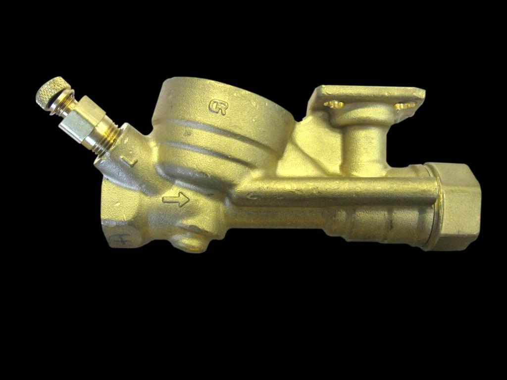
3 Call us on +44 (0) or visit Valve Specifications Sectional View - DN15/DN20 15 Very Low Low High Part Number PE81VL.04 PE81L.04 PE81H.04 Nominal [l/s] Max Flow l/h] 324 (396) 630 (770) 900 (1100) Nominal Min Flow [l/s] [l/h] Accuracy [0.2-4 Bar] ±10% ±10% ±10% Accuracy includes linearity and hysteresis. Start Up ΔP [kpa] Max Working ΔP [kpa] Working Pressure PN Min Temp [ C] Max Temp [ C] Connections Rp ["] 1/2 1/2 1/2 Connections are parallel BSP to BS-EN
4 Material Specification Body Forging DZR Brass CW602N 2 Cartridge Body Brass CW614N 3 Cartridge Seat Brass CW614N 4 Cartridge Spring Stainless Steel AISI Diaphragm EPDM 6 Ball Brass CW617N 7 Stem Brass CW614N 8 Stem O-Rings Viton Call us on +44 (0) or visit 4
5 Call us on +44 (0) or visit Dimensions No Actuator Dimension A B C D DN BEKR24 Actuator Dimension A B C D DN BELR24A Actuator Dimension A B C D DN

6 Valve Operation The EVOPICV-R pressure independent control valve consists of two main functional groups: 1. Differential pressure regulator 2. Characterised Ball valve for flow regulation and temperature control Pressure Regulator P2 Flow & Temperature Control P1 P3 B A 1. Differential Pressure Regulator The differential pressure regulator is the heart of the pressure independent control valve, by keeping a constant differential pressure across the valve seats constant flow and full authority temperature control can be achieved. Incoming pressure P1 is transmitted to the top face of the diaphragm, outgoing pressure P3 is transmitted to the underside of this same diaphragm. A constant effective differential pressure is maintained between P2 and P3. As P1 increases relative to P3 it acts on the diaphragm closing the shutter (A) against a seat (B) thereby lowering the effective differential pressure. As P1 decreases relative to P3 the diaphragm acts to open the shutter (A) from the seat (B) thus increasing the effective differential pressure. The diaphragm acts against a spring in order to balance the pressure control and stop the diaphragm oscillating. Functional Schematic Call us on +44 (0) or visit 6
 across which is held constant by")

7 Call us on +44 (0) or visit 2. Flow Rate Limitation and Temperature Control The temperature control element of the valve consists of an oblique pattern globe valve the differential pressure (P2-P3) across which is held constant by the differential pressure regulator. The authority (n) of a valve can be calculated from the pressure drops across that valve compared with the local system. In this case written as n P a P a P b In the case of a Pressure Independent Control Valve the system P b is close to 0 meaning that the authority is very close to 1. Flow rate limitation and modulating flow control are both achieved using a single characterised port in the ball element of the valve. As the differential pressure across this characterised port is held constant by the pressure regulator flow rate is now only a function of the cross sectional area of this port. As the ball closes against the Teflon seat a portion of the port is occluded, the characterised port has been designed such that the rate of change of area as the ball closes produces an equal percentage characteristic. Maximum flow rate limitation is achieved by limiting the position to which the ball may open. This can be achieved in two ways, firstly by means of a mechanical adaptor or more commonly by limiting the maximum opening position of the attached actuator. Modulating flow rate control is achieved by positioning the ball between the fully closed position and the point at which the design flow rate is achieved, in other the words the point at which the maximum opening position of the actuator is reached. Drawing showing how characterised ball is occluded by Teflon seat
8 Flow Control Figure A. Figure A. describes the general flow performance of the valve as the differential pressure changes. It can be seen that before the start-up pressure is achieved the flow rate increases almost as a fixed orifice valve. Once the start-up pressure has been achieved the valve controls the flow within a proportional band around the set point range. Values stated for the start-up pressure are calculated with the valve in the fully open position as the lowest differential pressure at which the valve will give a constant flow (±10% of nominal). It can be observed that as the valve is regulated to lower flow rates that the start-up pressure decreases. It can also be seen that once the working differential pressure range has been exceeded that the flow rate begins to rise out of the tolerance bands, however this happens at a much lower rate than a fixed orifice valve would exhibit. It should be noted that for a particular pressure a range of flows (within ± 10% of the nominal) can be produced depending on if the pressure is rising or falling. This hysteresis effect is typical of all dynamic balancing valves due to the internal tolerances of the pressure regulator. When designing the pipe system the start-up pressure should be used as the nominal resistance of the valve for pump sizing purposes. The proportional band of the valve accounts for both linearity and hysteresis effects. When deciding on tolerances for witnessing the proportional band (± 10%) of the valve should be taken in to account, we would suggest a tolerance of 0%, +20% is used. Call us on +44 (0) or visit 8
9 Call us on +44 (0) or visit PE81VL.04 - Flow Performance PE81L.04 - Flow Performance PE81H.04 - Flow Performance
10 Flow Rate [Kv/Kvmax] Flow Rate [Kv/Kvmax] Flow Rate [Kv/Kvmax] Power Output Temperature Control The valve characteristic is a measure of the rate at which the valve controls flow in relation to its opening position, authority is a measure of how well a valve performs in relation to its characteristic curve when in use. Exact curve depends on ΔT Flow Rate [Kv/Kv max ] Figure A. Coil Power Output Power output through a coil is related to water flow rate but it can be seen from figure A. that this relation ship is not linear. Figure A. shows that as flow increases the power output tends towards some maximum value. It can also be seen that power output increases rapidly from 0-50% of water flow and thereafter the rate of increase of power output decreases. The steepness of this curve is typically dependant on the temperature difference induced in the heating or cooling media (ΔT). Valve Characterisation Curves Stroke [H/H max ] Figure B. ON/OFF, Quick Acting Curve Stroke [H/H max ] Figure C. Linear Curve Stroke [H/H max ] Figure D. Equal Percentage Curve Call us on +44 (0) or visit 10
11 Power Output Power Output Power Output Call us on +44 (0) or visit Figure B. describes an ON/OFF or quick acting valve characteristic, it can be seen that flow rate increases rapidly until 30% of the valve stroke and then slowly thereafter. Figure C. describes a Linear valve characteristic, flow rate increases in direct linear proportion to the valve stroke. Figure D. describes an Equal Percentage (modified logarithmic) valve characteristic. It can be seen that flow rate increases slowly until the valve stroke is approximately 70% and thereafter flow rate increases rapidly. It is generally desirable that the power output of a coil is linear in relation to the valve stoke as this results in the most easily controllable situation. System Response Curves Stroke [H/H max ] Stroke [H/H max ] Stroke [H/H max ] Figure E. (Fig A. + Fig B.) Figure F. (Fig A. + Fig C.) Figure G. (Fig A. + Fig D.) Figure E. describes the system response (power output of a coil vs. valve stroke) when a quick acting or ON/OFF valve is used. It can be observed that the power output rises to over 95% before the valve is more than 20% open. Figure F. describes the system response when a linear valve is used, it can be seen that power output rises quickly for the first 50% of valve stroke and thereafter the rate of change decreases. It can also be seen that 95% of the power output is achieved with a valve stroke of approximately 80%. Figure G. describes the system response when an equal percentage valve is used, it can be observed that power output increases linearly with increasing valve stroke. From the above graphs it can be seen that the equal percentage characteristic gives the most desirable system response. It should be noted that in any practical system the valve characteristic and coil characteristics may not be 100% matched but an equal percentage characteristic valve will always give a more linear response than any other profile. The characteristic curves of the EVOPICV-R valves are shown overleaf.
12 Characterisation of the regulating ball. The diagram below shows the free area of passage at various opening positions, it can be seen that as the ball opens up to 50% open only a very small area of passage is presented. As the ball opens to 75% a much greater area of passage is formed until at 100% open the full area of passage is presented. This rate of change of area of passage is the factor which governs the valve characteristic. The characterised slot is laser cut directly into the ball, this allows the characterisation profile to be very precise and repeatable. 0% Open 25% Open 75% Open 100% Open Open % Open 81VL 81L 81H 0% % % % % % % % % % % Flow Rate at Each Position Call us on +44 (0) or visit 12

![00% 40.00% 20.00% 0.00% 0% 20% 40% 60% 80% 100% [%] H/H Max PE81L.](/docs-images/90/103719837/images/13-1.jpg "04 - Characteristic Curves 100.00% 80.00% [%] Kv/KvMax 60.00% 40.00% 20.")

13 Call us on +44 (0) or visit PE81VL.04 - Characteristic Curves % 80.00% [%] Kv/KvMax 60.00% 40.00% 20.00% 0.00% 0% 20% 40% 60% 80% 100% [%] H/H Max PE81L.04 - Characteristic Curves % 80.00% [%] Kv/KvMax 60.00% 40.00% 20.00% 0.00% 0% 20% 40% 60% 80% 100% PE81H.04 Characteristic Curves % [%] H/H Max [%] Kv/KvMax 80.00% 60.00% 40.00% 20.00% 0.00% 0% 20% 40% 60% 80% 100% [%] H/H Max

14 Actuators The EVOPICV-R has been designed with an ISO standard mounting arrangement that can accommodate actuators with both ISO4 and ISO5 mounting pads. This means that almost any type of rotary valve actuator may be used with the valve so long as the minimum torque requirements are met. A wide range of actuators are available from Marflow for the EVOPICV-R valves, split into three functional types. 3 Point floating (Raise/Lower, Drive Open/Drive Close Actuators) 0-10v Proportional Actuators Programmable Multifunction Actuators BELR24A-MF Factory Setting Range Control Type 0-10v v Characteristic Linear 3 Point Operating Voltage [V] AC/DC 24v ±20% Open/Close Operating Power [W] 2 Quiesent Power [W] 1.2 Wiring [VA] 3.5 Actuating Torque [Nm] 5 Angle Of Rotation [ ] 90 Feedback [V] 2-10v v Run Time [s] Operating Temperature [ C] Fluid Temperature [ C] 5-80 Max Relative Humidity [%] 95 IP Rating 54 Cable Type 4 x 0.75 mm² Cable Length [mm] 1000 Housing Colour Orange Dimensions H/W/L [mm] 84/71/182 Input Resistance [kω] 100 Common Black 1 Live Red 2 Control White 3 Feedback Orange 5 Call us on +44 (0) or visit 14
![Call us on +44 (0)845 564 1555 or visit www.marflowhydronics.co.uk BEKR24 Control Type 3 Point Characteristic Linear Operating Voltage [V] AC/DC 24v ±20% Operating Power [W] 1 Quiesent Power [W] 0.](/docs-images/90/103719837/images/15-0.jpg "2 Wiring [VA] 2 Actuating Torque [Nm] 5 Angle Of Rotation [ ] 90 Run Time [s] 90 Operating Temperature [ C] 0-50 Fluid Temperature [ C] 5-110 Max Relative Humidity [%] 95 IP Rating 54 Cable Type 3 x")
![0.75 mm² Cable Length [mm] 1000 Housing Colour Orange Dimensions H/W/L [mm] 84/71/160 Common Black 1 Close Red 2 Open White 3 BEKR24 Control Type 3 Point Characteristic Linear Operating Voltage [V]](/docs-images/90/103719837/images/15-1.jpg "AC/DC 24v ±20% Operating Power [W] 0.5 Quiesent Power [W] 0.")
15 Call us on +44 (0) or visit BEKR24 Control Type 3 Point Characteristic Linear Operating Voltage [V] AC/DC 24v ±20% Operating Power [W] 1 Quiesent Power [W] 0.2 Wiring [VA] 2 Actuating Torque [Nm] 5 Angle Of Rotation [ ] 90 Run Time [s] 90 Operating Temperature [ C] 0-50 Fluid Temperature [ C] Max Relative Humidity [%] 95 IP Rating 54 Cable Type 3 x 0.75 mm² Cable Length [mm] 1000 Housing Colour Orange Dimensions H/W/L [mm] 84/71/160 Common Black 1 Close Red 2 Open White 3 BEKR24 Control Type 3 Point Characteristic Linear Operating Voltage [V] AC/DC 24v ±20% Operating Power [W] 0.5 Quiesent Power [W] 0.2 Wiring [VA] 1 Actuating Torque [Nm] 2 Angle Of Rotation [ ] 90 Run Time [s] 75 Operating Temperature [ C] Fluid Temperature [ C] 5-80 Max Relative Humidity [%] 95 IP Rating 54 Cable Type 3 x 0.75 mm² Cable Length [mm] 1000 Housing Colour Orange Dimensions H/W/L [mm] 34/56/164 Common Black 1 Close Red 2 Open White 3
16 Wiring diagram, 3-Point actuators. Wiring diagram, 0-10v actuator. Setting Maximum Flow Rate To set the selected flow, follow these steps: Maximum flow rate limitation to a particular design flow rate can be achieved in practice by the following methods Mechanical setting device and manual flow measurement A mechanical device (TBR) may be fitted to the valve in order to limit the maximum opening position of the valve. A flow measurement device should also be installed. The valve should be opened manually until the deign flow rate is measured on the flow measurement device, once this is achieved then the manual regulating device can be locked in position. Manually limiting the drive time or scaling the control voltage in each BMS controller (not recommended). Using the control curves for each valve the drive time (or control voltage) for a particular flow rate can be calculated. This drive time or control voltage can then be programmed into each building management system controller. e.g. A valve is selected and the design flow rate required equates to an open position of 60 degrees (90 degrees being fully open). The actuator selected has a drive time of 90 second (or 1 second per degree) it can be calculated that the drive time required to achieve design flow is 60 seconds. This is the drive time that should be programmed into the BMS controller. Using a programmable actuator The programmable actuator internally scales its drive time to provide a particular design flow rate. The actuator can be delivered pre-programmed but is also settable on site using the programming tool. In order to program the actuator the opening percentage for a particular valve should be calculated, the example below shows the procedure for this calculation. Once the opening position has been determined the programming tool can be used program this into the actuator. Call us on +44 (0) or visit 16
17 Call us on +44 (0) or visit If desired the programming tool can also be used in concert with a flow measurement device. Whist reading from the flow measuring device the programming tool can be used to drive the valve to any position form 0 100%, when the desired flow reading is achieved the programming tool can be used to set this opening percentage in the actuator. It should be noted that the setting scale on the programming device is a linear percentage (i.e % 0% = 0 50 = % = 90 ) however because the the valve characteristic follows a square function the percentage setting must be calculated from the square root of the ratio of design flow over maximum valve flow. For Example; A design flow rate of 0.05 l/s is required and a PEB81VL.04 (Maximum Nominal Flow 0.1 l/s) has been selected, the percentage setting is calculated as follows. Using a remote commissioning capable BMS control strategy By using a remote commissioning capable BMS controller the design flow rate can be directly programmed into the BMS controller. For more information on remote commissioning and controlling the valve in this way please see our dedicated remote commissioning documentation.
18 Flushing and Media Quality It is expected that the system to which the EVOPICV-R is fitted be pre cleaned and flushed in accordance to the standards and principles detailed in the BSRIA guide Pre commission cleaning of pipework systems (BG29/2011) and the water quality maintained to standards as detailed in BSRIA guide Water treatment for building service systems. Please ensure the compatibility of any cleaning agents and water treatments with the materials listed at the front of this datasheet. It should be noted that because the pressure independent valve will limit flow to a pre-set value regardless of the differential pressure, the valve should not be forward flushed when mounted in the flow connection. It is recommended that if the terminal units need to be flushed that the system is flushed to drain whilst bypassing the EVOPICV-R. On systems where the water quality is not known or is known to be poor it is recommend that a strainer is fitted to protect the EVOPICV-R. Verification In order to verify that a particular valve is within its working range the differential pressure can be measured across the installed pressure test points, if this pressure is between the upper and lower differential pressure limits (20kPa and 400kPa) the valve is within it operational range. Note: flow rate cannot be measured across the EVOPICV-R using the incorporated test points as due to the internal function of the valve the KV is not fixed. If flow measurement is required a separate orifice plate or venturi should be installed downstream. Before onsite verification commences it should be ensured that; The circulation pump has been correctly sized. The circulation pumps are operating in constant pressure or proportional pressure mode. The system has been flushed and treated. The system is free of air. Any local strainers are clean and have remained clean for at least 24hrs of pump operation. All actuators are driven fully open. CIBSE Commissioning Code W (2010) covers the verification of PICVs in section W7.7.3 Summated flow measurement at the branch and sub mains. Since each of the EVOPICV-R valves give a constant flow the expected flow at the branch or sub mains measuring station will be the sum of all the expected flows down stream of that measuring station. If the measured flow is within ±10% of the expected flow then it can be said that all the PICV valves are functioning correctly. Further problem solving can be carried out if necessary by means of either direct flow measurement at the terminal units or by the Marflow Single Station Balancing method. Direct flow measurement at the terminal units. The flow rate can be verified by direct flow measurement at each terminal unit if it is thought necessary however it would be more usual to measure the flow rate at 10% of the terminal units and only investigate further if discrepancies are found. Optimisation When the verification stage is complete the system can be optimised for energy usage by reducing the pump speed. In order to do this the index loop must be identified, this will be the Pressure independent valve that has the lowest differential pressure across it. When the index loop has been identified the pump speed may be lowered until the pressure drop across the index PICV is equal to or just above 1.5 times the start-up pressure for that valve. This will ensure excess energy is not used in circulating water around the system. Call us on +44 (0) or visit 18
19 Call us on +44 (0) or visit Reference Terminal Unit Schematics PICV Constant Flow Regulator Flow Mounted, Variable Volume System with local flow measurement Filterball Isolating Strainer Flow Measurement Valve Return Mounted, Variable Volume System Isolation Valve Coil/Heat Emitter 3 Port Control Valve Return Mounted, Constant Volume System


20 Marflow Hydronics Limited Britannia House Austin Way Hamstead Industrial Estate Birmingham, England B42 1DU XLIT-EVOPICVR-04/12 Tel Fax Errors and Omissions Excepted, Marflow reserve the right to change specification at any time
Terminator PICV. Technical Manual
 Terminator PICV Technical Manual Table of Contents Introduction 1 Advantages and Ease of Use 1 Applications examples 2 Technical specifications Start Up Charts 6 Start Up Charts 7 Start Up Charts 8 Flow
Direct/Factory Mounting Valve Set
 Generated: 29th April 2018 Marflow Hydronics 1 Dimensions DN 15/20 A 243 B 137 C 115 D 3/4 Euroconus d 40 E 30.2 Generated: 29th April 2018 Marflow Hydronics 2 Product Variations NX-EVO-X-X-03 Part No:
Pressure Independent Control Valve
 Pressure Independent Control Valve Rev. 4.0-06/06/2011 Technical manual Introduction The Pressure Independent Control Valve PICV is a combined constant flow limiter and full stroke, full authority equal
VE-S_15-32 Pressure Independent Balancing & Control Valves
 Page 1 of 9 VE-S_15-32 Pressure Independent Balancing & Control Valves (PIBCV) is used in heating and cooling systems in applications with Fan Coil Units, Chilled Beams or other terminal unit applications.
Technote. Frese OPTIMA Compact DN10-DN50 - pressure independent balancing & control valve. Application. Features. Benefits.
 Page of 5 Frese OPTIMA Compact DN-DN5 Application Frese OPTIMA Compact pressure independent balancing & control valve (PIBCV) is used in heating and cooling systems in applications with Fan Coil Units,
PCS. HVAC Products. Technical submission. Type of Product
 Technical submission R 1.1 Type of Product XT series complete Terminal valve assembly for fixed and adjustable flushing by-pass for axial PICV. This technical submittal contains information that to the
Technote. Frese OPTIMA - Pressure independent control & balancing valve. Application. Features. Benefits.
 Page 1 of 12 Application pressure independent control valve (PICV) is used in heating and cooling systems in applications with Fan Coil Units, Air Handling Units or other terminal unit applications. provides
Pressure Independent Control Valve
 Pressure Independent Control Valve www.ballorex.com Table of contents Chapter Ballorex Dynamic DN 15L-50H 1. Safety instructions 4 1.1 Rules/regulations 4 1.2 Intended use 5 1.3 Initial operation 5 1.4
Pre-Fabricated Flushing Bypass Assembly for Plant Applications Hero Plant DN15-150
 Pre-Fabricated Flushing Bypass Assembly for Plant Applications Description Hero Plant is a pre-fabricated, flushing bypass arrangement for balance, control, isolation, and operation of plant devices. Flow
Product Sheet Pre-Fabricated Flushing Bypass Assembly for Terminal Applications Mini-Flush 40
 Product Sheet Pre-Fabricated Flushing Bypass Assembly for Terminal Applications Mini-Flush 40 Description Miniflush40 is a pre-fabricated, flushing bypass arrangement for balance, control, isolation, and
Product Sheet Pre-Fabricated Flushing Bypass Assembly for Plant Applications Hero Plant DN15-150
 Product Sheet Pre-Fabricated Flushing Bypass Assembly for Plant Applications Hero Plant DN15-150 Description Hero Plant is a pre-fabricated, flushing bypass arrangement for balance, control, isolation,
VP1000. Pressure Independent Control Valve. Product Bulletin
 VP1000 Pressure Independent Control Valve Product Bulletin VP1000 Pressure Independent Control Valve is a combination of a differential pressure regulator and a regulating valve for flow adjustment. VP1000
Pressure Independent Control Valve
 Pressure Independent Control Valve www.ballorex.com Table of contents Chapter Ballorex Dynamic DN 15L-50H 1. Safety instructions 4 1.1 Rules/regulations 4 1.2 Intended use 5 1.3 Initial operation 5 1.4
Balancing Valves. Venturi Commissioning Valve (FODRV) & (DRV) Cu x Cu Compression DN10-DN50. BOSS TM 901SC Venturi DRV DN
 & (DRV) Cu x Cu Compression DN10-DN50. BOSS TM 901SC Venturi DRV DN") Venturi Commissioning Valve (FODRV) & (DRV) Cu x Cu Compression DN-DN Balancing Valves BOSS TM 900SC Venturi FODRV DN1- BOSS TM 901SC Venturi DRV DN1- Specification The commissioning station and DRV incorporates
Venturi Commissioning Valve (FODRV) & (DRV) Cu x Cu Compression DN-DN Balancing Valves BOSS TM 900SC Venturi FODRV DN1- BOSS TM 901SC Venturi DRV DN1- Specification The commissioning station and DRV incorporates
Ballorex Venturi 3.1 Introduction
 3.1 Introduction Venturi Fixed Orifice Double Regulating Valve (FODRV) DN 15-600 1/2-24 Venturi description The Venturi is a range of manual balancing valves used in water-based heating and cooling systems
2-port and 3-port ball valves PN 40
 s 4 211 VAI61.. VBI61.. ACVATIX TM 2-port and 3-port ball valves PN 40 with internally threaded connections VAI61.. VBI61.. Brass UNS C35330 (DZR) ball valve body DN 15...50 k vs 1...63 m 3 /h Internally
Pressure Independent Control Valve. Technical manual
 Pressure Independent ontrol Valve Technical manual STE0101 R6-12/09/2013 Table of contents Introduction...1 Advantages and user-friendliness...1 Applications examples...2 Technical specifications...3
Technote. Frese ALPHA HCR Dynamic Balancing Valve. Application. Features. Benefits. Design. Installation. Operation.
 Page 1 of 7 Application The (High Corrosion Resistant) Valves are particularly designed and manufactured for automatic balancing in Industrial applications. An integral part of the Valve is the ALPHA Cartridge,
FCU 6-PORT PICV VALVE SET MODULE BROCHURE
 FCU 6-PORT PICV VALVE SET MODULE BROCHURE Copyright. February 2019 FLOCONTROL DESIGNS AND ASSEMBLES BESPOKE FCU VALVE SETS TO ADDRESS PROJECT-SPECIFIC REQUIREMENTS FloControl offers a comprehensive range
VZ*19* VZ219E, VZ319E, VZ419E VZ219C, VZ319C, VZ419C
 VZ219E, VZ319E, VZ419E VZ219C, VZ319C, VZ419C SPECIFICATIONS Design PN16, Two-way, Three-way and Three-way with bypass (Linear operation) Function.... Normally Closed (A-AB). [Without actuator fitted]
FlowCon Energy FIT System
 Energy FIT System Energy-Saving Pressure and Temperature Independent System 65-250 mm / 2 1/2-10 SPECIFICATIONS PICV valve: Static pressure: 4000 kpa / 580 psi Ambient temperature: -10 C to +50 C / +14
Balancing Basics. Mike Weisman, ASHRAE Treasurer. ASHRAE Golf Outing: May 18 th, 2018! HEATHERWOODE
 Balancing Basics Mike Weisman, ASHRAE Treasurer ASHRAE Golf Outing: May 18 th, 2018! HEATHERWOODE Agenda: Why balance? Manual Balancing Valves Manual Balancing Process Automatic Flow Controllers Partial
Fig.306F (DN50-150) Pressure Independent Control Valve (PICV)
 Pressure Independent Control Valve (PICV)") Installation, Operating and Maintenance Instructions Fig.306F (DN50-150) Pressure Independent Control Valve (PICV) GENERAL NOTES The Hattersley Fig.306F: Can be used in variable volume heating and chilled
Installation, Operating and Maintenance Instructions Fig.306F (DN50-150) Pressure Independent Control Valve (PICV) GENERAL NOTES The Hattersley Fig.306F: Can be used in variable volume heating and chilled
Open/close ball valves 2-port and changeover ball valves 3-port, PN40
 s 4 213 VAI60.. VI60..L VI60..T ACVATIX TM Open/close ball valves 2-port and changeover ball valves 3-port, PN40 with internally threaded connections VAI60.. VI60..L VI60..T rass UNS C35330 (DZR) ball
Flow Data for NIBCO Circuit Balancing Valves 1/2 to 2 (Figure Number 1710)
") NIBCO INC. WORLD HEADQUARTERS 1516 MIDDLEBURY ST. ELKHART, IN 46516-4740 USA PHONE: 574.295.3000 FAX: 574.295.3307 WEB: www.nibco.com INSTALLATION, OPERATION & MAINTENANCE INSTRUCTIONS Flow Data for NIBCO
NIBCO INC. WORLD HEADQUARTERS 1516 MIDDLEBURY ST. ELKHART, IN 46516-4740 USA PHONE: 574.295.3000 FAX: 574.295.3307 WEB: www.nibco.com INSTALLATION, OPERATION & MAINTENANCE INSTRUCTIONS Flow Data for NIBCO
Figure 1710 Flow Data
 AHEAD OF THE FLOW Figure 1710 Flow Data Circuit Balancing Valve Why balance your system? Whether a system is designed for heating or chilling it must be properly adjusted and balanced for optimum design
P2050S-030, 1/2, Electronic Pressure Independent Valve Stainless Steel Ball and Stem, Female NPT Ends
 P2050S-030, 1/2, Electronic Pressure Independent Valve Stainless Steel Ball and Stem, Female NPT Ends Application Water-side control of heating and cooling systems for AHUs and water coils. Equal Percentage/
Automatic balancing valves ASV-PV DN (3rd gen.)
") Automatic balancing valves ASV-PV DN 50-100 (3rd gen.) Description / Application Partner valve ASV-PV DN 50 ASV-PV DN 65-100 MSV-F2 DN 50-100 ASV balancing valves are used for dynamic hydronic balance
Automatic balancing valves ASV-PV DN 50-100 (3rd gen.) Description / Application Partner valve ASV-PV DN 50 ASV-PV DN 65-100 MSV-F2 DN 50-100 ASV balancing valves are used for dynamic hydronic balance
Product bulletin for: ST2 Ball valves with two-way and three-way BSPP threaded fittings
 Product bulletin for: ST2 Ball valves with two-way and three-way BSPP threaded fittings ST2 Ball valves in conjunction with spring return and non-spring return VA-Actuators Developed for HVAC applications
Combined automatic balancing valve AB-PM valve DN 10-32, PN 16
 Data sheet Combined automatic balancing valve AB-PM valve DN 10-32, PN 16 Description AB-PM is a combined automatic balancing valve. It features three function in compact valve body: 1. Differential pressure
Modulating control valve PN16 with magnetic actuator
 Modulating control valve PN with magnetic actuator for hot and chilled water with positioning control and position feedback MP80FY MP00FY Mixing or straight-through valves DN80 and DN00 with magnetic actuator
VG6000 Series Forged Brass Valves
 VG6000 Series Forged Brass Valves Product Bulletin PB_VG6000 Issue Date 04 2008 The VG6000 forged brass valve series is primarily designed to regulate the flow of water in response to the demand of a controller
Modulating control valve PN16 with magnetic actuator
 Modulating control valve PN with magnetic actuator for hot and chilled water with positioning control and position feedback MP...GY MP...FY MP...GY MP...FY Mixing or straight-through valves with magnetic
2-port ball valves with flanged connection, PN25
 s 4 120 ACVATIX 2-port ball valves with flanged connection, PN25 VAF51.. Gray cast iron EN-GJL-250 (HT250) valve body DN 65...150 k vs 63...360 m 3 /h Angle of rotation 90 Flange connection to ISO 7005-2
VPI45.. VPI45..Q. Combi valves, PN 25. Building Technologies. VPI45..Q with pressure test points ACVATIX
 4 853 VPI45.. VPI45..Q with pressure test points ACVATIX Combi valves, PN 25 for rooms, zones, air handling units as well as small to medium heating, ventilation and air-conditioning systems VPI45.. VPI45..Q
HERZ-Connect 4 / Compact Connect 4 & Commissioning Centres
 www.herz.eu HERZ-Connect 4 / Compact Connect 4 & Commissioning Centres Simple and cost efficient methodes of thermal units control 1 Connect 4.indd 1 17.11.2015 10:31:20 HERZ- Connect 4 HERZ Connect-4
CIMBERIO VALVES. SAV Systems. Product Brochure.
 CIMBERIO VALVES SAV Systems Product Brochure www.sav-systems.com Rev: 1.0 08/2010 CIMBERIO VALVES Balancing Valves Isolation Valves Check Valves Gas Valves Page 6 10 21 23 3 ABOUT SAV SYSTEMS SAV Systems
Technote. Frese OPTIMIZER - pressure independent 4-pipe coil control unit. Application. Benefits. Features.
 Page of 7 Application control unit, in conjunction with the associated hydraulic set provides a complete pressure independent balancing and control group for efficient and effective individual room or
3-port seat valves, external thread, PN16
 4 464 3-port seat valves, external thread, PN6 VXG44.. ronze CC49K (Rg5) valve body DN 5..DN 40 k vs 0.25..25 m 3 /h Flat sealing connections with external thread G to ISO 228- Sets of ALG..3 screwed fittings
FO-BV Series. Fixed-orifice balancing and control valves. Technical Data Sheet. WattsIndustries.com
 FO-BV Series Fixed-orifice balancing and control valves Technical Data Sheet WattsIndustries.com Description FO-BV Series fixed-orifice threaded valves are designed for flow control and monitoring in climate
TRF.. series spring return rotary actuators for CCV
 TF.. series spring return rotary actuators for CCV Spring return rotary actuators: For ball valves DN 5.. Torque: 2 Nm Modulating control TF24-S (C/DC 24 V) Floating (3-point) control TF24-2 (C/DC 24 V)
Ballorex Vario. Description. Versions. Benefits. Applications. Balancing
 Ballorex Vario Description Ballorex Vario is a variable orifice double regulating valve for balancing water-based heating and cooling systems. The balancing performed ensures the required distribution
Pressure independent balancing and control valve AB-QM DN
 Data sheet Pressure independent balancing and control valve AB-QM DN 10-250 The AB-QM valve equipped with an actuator is a control valve with full authority and an automatic balancing function / flow limitation.
CBV Series. Circuit Balancing Valves
 CBV Series Circuit Balancing Valves FILE NO: 36.10IN DATE: Dec. 15, 2010 SUPERSEDES: 36.10IN DATE: Nov. 05, 2009 CBV Series Circuit Balancing Valves - Introduction Circuit balancing valves (CBVs) combine
The Siemens 599 Series Ball Valve Portfolio simplifies installations and maximizes control usa.siemens.com/hvac
 Two-,Three-, and Six-Way Ball Valves The Siemens 599 Series Ball Valve Portfolio simplifies installations and maximizes control usa.siemens.com/hvac Ready for the Challenge With higher close-offs, a wider
2-port seat valves PN16 with flanged connection
 4 330 Acvatix 2-port seat valves PN16 with flanged connection VVF40.. Grey cast iron EN-GJL-250 valve body DN 15...150 k vs 1.9...315 m 3 /h Can be equipped with SAX..-electromotoric or SKD..-, SKB..-
TA-6-way valve. Standard control valves 6-way valve for change-over systems
 TA-6-way valve Standard control valves 6-way valve for change-over systems IMI TA / Control valves and Actuators / TA-6-way valve TA-6-way valve The 6-way valve solution enables various control set-ups
TA-6-way valve. NPT threads. Standard control valves 6-way valve for change-over systems
 T-6-way valve NPT threads Standard control valves 6-way valve for change-over systems IMI T / Control valves / T-6-way valve NPT threads T-6-way valve NPT threads The 6-way valve solution enables various
Connection and regulation kit for HVAC terminal units
 Connection and regulation kit for HVC terminal units 149 series 01336/18 G FM 21654 003 Function The preassembled group for terminal units is compact and able to shutoff, adjust and filter the secondary
CONTENTS. Double Flow Measurement Device 1. Fixed Orifice Double Regulating Valve 3. Variable Orifice Double Regulating Valve 7
 CONTENTS Double Flow Measurement Device 1 Fixed Orifice Double Regulating Valve 3 Variable Orifice Double Regulating Valve 7 Flow Measurement Graphs for Fixed Orifice Devices 9 for Variable Orifice Devices
BALANCING VALVES FOR BUILDING
 ICV TOTAL CONTROL INSIDE BUILDINGS IC Valves (Nanjing) Co., Ltd. Changfa Centre Bldg A, G Zhongshan East Road Nanjing 210002. China 20-08 Copyright IC Valves (Nanjing) Co., Ltd. Tel: +86 8320 0100 +86
R2F Compact Commissioning & 4 Port Control Valve Fan Coil Unit Valve Set Module
 R2F Compact Commissioning & 4 Port Control Valve Fan Coil Unit Valve Set Module The R2F Compact Commissioning & 4 Port Valve FCU Module concept offers a pre-assembled, tested compact Ready to Fit unit
Pressure independent balancing and control valve AB-QM DN
 Pressure independent balancing and control valve AB-QM DN 10-150 AB-QM valve equipped with an actuator is a control valve with full authority and automatic balancing function - flow limiter. Typical applications
ATi Max Series. Pressure Independent Control Valves 2 Way 2-1/2-6
 The Auto Touch Independent Max (ATiMX) valve brings pressure independent control technology to valves up to 6 and flow rates up to 468 GPM. It is a state-of-the-art control valve combining a high quality/
TA-Mini-Fast-Fit. Prefab units Fabricated solutions for small terminal units
 TA-Mini-Fast-Fit Prefab units Fabricated solutions for small terminal units IMI TA / Control valves / TA-Mini-Fast-Fit TA-Mini-Fast-Fit Compact pressure independent solution for modulating or on/off control.
Spring Achieve System Balance Without All The Spin. PICCV. Complete Details Inside!
 Spring 2005 Achieve System Balance Without All The Spin. PICCV Complete Details Inside! Valve Selection Has Never Been Easier! Simply choose the smallest PICCV that can satisfy the flow rate of your system.
DESCRIPTION 9.4 G 3/4"M
 DESCRIPTION Six-way ballvalve for HVAC 4 pipes applications to automatically carry out the winter-summer change-over or, potentially, to manage radiant ceilings, fan coils and chilled beams. DIMENSIONS
Characterized Control Valves Actuators. Technical Databook Ver. 2
 Characterized Control Valves Actuators Technical Databook Ver. 2 Product overview and table of contents Table of contents 2 Control valves and actuators Product overview The Trane Ball valves The Trane
ChangeOver6 and NovoCon ChangeOver6 - Motorized 6-port Ball Valves
 - Motorized 6-port Ball Valves Description NovoCon The and NovoCon are 6-port motorized ball valves that performs a diverting function between two water circuits in 4-pipe changeover system. This diverting
VE-x Plug & Seat Valve Assemblies
 Page 1 of 5 Plug & Seat Valve ssemblies Features: Suitable for water or glycol mix 1½ million cycle U-cup packing cartridge Maintenance free High and low Kvs of each size ll metal movement, no plastic
CALEFFI. Pre-assembled distribution manifolds for radiant panel systems. series 663 & /05 NA. Function
 Pre-assembled distribution manifolds for radiant panel systems series & / NA Function Distribution manifolds for radiant panel systems are used to optimally distribute the heating fluid in floor heating
Product Table of overview contents and table of contents. Table of contents
 Product able of overview contents and table of contents able of contents Product overview he Belimo characterized control valves (CCV) he Belimo characterized control valves (CCV), notes he sizing of ball
VPI45..Q with pressure test points. Combi valves, PN 25
 4 853 VPI45.. VPI45..Q with pressure test points ACVATIX Combi valves, PN 25 for rooms, zones, air handling units as well as small to medium heating, ventilation and air-conditioning systems VPI45.. VPI45..Q
Description. Ballorex Venturi. Versions. Benefits. Robinets manuels Balancing
 Ballorex Venturi Description The Ballorex Venturi is a range of manual balancing valves used in water-based heating and cooling systems to ensure an evenly distributed flow in zones, branches, risers and
Globe Valves. Technical Databook Version 1.2. Belimo Asia Pacific
 Globe Valves Technical Databook Version 1.2 Belimo Asia Pacific Contents Globe Valves Product Overview Max. Close-off Pressure - Globe Valve Series Globe Valve Actuators Product Overview 4 5 General Information
Innovation + Quality. Valves, controls + systems Balancing and Control Valves
 Innovation + Quality Valves, controls + systems Balancing and Control Valves Balancing and Control Valves Catalog Hydrocontrol Static Balancing Valves Recomended flow rate chart 4 Hydrocontrol VTR Static
TECHNICAL SPECIFICATIONS 63/2E DN15 Kvmax /4"E. ( 3 4"x18) 3/4"E
 3/4E") DESCRIPTION 63/2E Six-way ballvalve with ¾ M eurocone ends for HVAC 4 pipes applications to automatically carry out the winter-summer change-over or, potentially, the control of radiant ceilings, fan coils
DESCRIPTION 63/2E Six-way ballvalve with ¾ M eurocone ends for HVAC 4 pipes applications to automatically carry out the winter-summer change-over or, potentially, the control of radiant ceilings, fan coils
Combi valves, PN 25. for rooms, zones, ventilation and air-conditioning systems
 4 855 VPP46.. VPI46.. VPP46..Q, with pressure test points P/T VPI46..Q, with pressure test points P/T ACVATIX Combi valves, PN 25 for rooms, zones, ventilation and air-conditioning systems VPP46.. VPP46..Q
CHBE320 LECTURE III ACTUATOR AND CONTROL VALVE SELECTION. Professor Dae Ryook Yang
 CHBE320 LECTURE III ACTUATOR AND CONTROL VALVE SELECTION Professor Dae Ryook Yang Spring 2018 Dept. of Chemical and Biological Engineering 3-1 Visit Actuator Road Map of the Lecture III + - Controller
20 to 150 mm 2-Way Automatic Flow Balancing Control Ball Valves
 VFB30 Series Issue Date February 1, 2016 20 to 150 mm 2-Way Automatic Flow Balancing Control Ball Valves Low Torque Facilitates the use of smaller, less expensive directmount rotary-motion actuators Extends
VPP46.. Combi valves, PN 25 VPP46..Q VPI46.. VPI46..Q ACVATIX. for rooms, zones, ventilation and air-conditioning systems
 4 855 VPP46.. VPI46.. VPP46..Q, with pressure test points P/T VPI46..Q, with pressure test points P/T ACVATIX Combi valves, PN 25 for rooms, zones, ventilation and air-conditioning systems VPP46.. VPP46..Q
Combi valves PN 16 with flanged connections
 4 315 ACVATIX Combi valves PN 16 with flanged connections Pressure Independent Combi Valves VPF43.. With integrated pressure differential controller Valve body made of gray cast iron GJL-250 DN 50, DN
AUTOMATIC CONTROL VALVES. TIS asia
 AUTOMATIC CONTROL VALVES VALVES DEDICATED TO THE WATER DISTRIBUTION NETWORK AND HYDROPOWER SECTOR WE DO NOT SELL JUST VALVES, WE SELL A SOLUTION FOR THE EFFICIENCY OF THE WATER NETWORK TIS asia MADE IN
Pressure independent balancing and control valve
 Pressure independent balancing and control valve AB-QM DN 10-150 AB-QM valve equipped with an actuator is a control valve with full authority and automatic balancing function - flow limiter. Typical applications
3-port seat valves PN16 with flanged connection
 4 430 Acvatix 3-port seat valves PN16 with flanged connection VXF40.. Grey cast iron EN-GJL-250 valve body DN 15 150 k vs 1.9 315 m 3 /h Can be equipped with SQX.. electromotoric or SKD..-, SK..- and SKC..-
Differential pressure controller with flow limitation and with integrated control valve (PN 16) AHPBM-F flow mounting, fixed setting
 AHPBM-F flow mounting, fixed setting") Data sheet Differential pressure controller with flow limitation and with integrated control valve (PN 16) AHPBM-F flow mounting, fixed setting Description The controller has a control valve with adjustable
Data sheet Differential pressure controller with flow limitation and with integrated control valve (PN 16) AHPBM-F flow mounting, fixed setting Description The controller has a control valve with adjustable
2-position electric actuators with Ball valves VBZ ½...11/4
 4 831.2 & VBZ ½...11/4 2-position electric actuators with Ball valves VBZ ½ 11/4 90 angle - Unidirectional rotation VBZ ½ 11/4 Electric rotary actuators for two-port ball valves Operating voltage AC 230
Pressure Independent Control Valve Applications for Building Automation, Temperature Controls, and HVAC Two-Way Chilled Water Hot Water
 Rev: 08/19/2013 (ATiMX) Features Pressure Independent Control Valve Applications for Building Automation, Temperature Controls, and HVAC Two-Way Chilled Water Hot Water The Auto Touch Independent Max (ATiMX)
HVAC Products PCS. Pettinaroli Commissioning Solutions
 HVAC Products PCS Pettinaroli Commissioning Solutions PCS Commissioning kits for terminal units Pettinaroli s versatile range of valve assemblies for fan coils, chilled beams and other hydronic terminal
Pre-assembled distribution manifolds for radiant panel systems
 Pre-assembled distribution manifolds for radiant panel systems Function Distribution manifolds for radiant panel systems are used to optimally distribute the heating fluid in floor heating system circuits
Modulating control valve PN16
 8 Modulating control valve PN with magnetic actuator for HTHW and steam, with positioning control and position feedback MH...FY...N Control valve with magnetic actuator for modulating control in district
3-Port Seat Valves with Male Thread, PN 16
 6 3-Port Seat Valves with Male Thread, PN 6 VXG ronze CC9K (Rg5) valve body DN 5DN 0 k vs 02525 m 3 /h Flat sealing connections with external thread G to ISO 228/ Sets of ALG 3 screwed fittings with threaded
Automizer Combination Control Valves
 Combination Control Valves Recommended Applications Where actuated valves and balancing valves are used to control the flow For VAV boxes, fan coil units and terminal boxes Where space is tight Absolute
3-port seat valves PN16 with flanged connection
 4 440 Acvatix 3-port seat valves PN16 with flanged connection VXF41.. Grey cast iron EN-GJL-250 valve body DN 15...150 k vs 1,9...300 m 3 /h Can be equipped with SAX..-electromotoric or SKD..-, SK..- and
2-Port and 3-Port Zone Valves, PN 16 / 20
 4 867 2-port valve MVI421.15 to MVI421.25 3-port valve MXI421.15 to MXI421.25 2-Port and 3-Port Zone Valves, P 16 / 20 Max. permissible pressure 2000 kpa MVI421.. MXI421.. Operating voltage C 230 V, 2-position
VG9000 Flanged Valves
 VG9000 Flanged Valves DN15..., PN6 and PN10 Product Bulletin This improved VG9000 Series cast iron flanged valves are designed primarily to regulate the flow of water and low pressure steam in response
VPA Series and VAP Actuator
 VPA Series and VAP Actuator PN6 Flanged Pressure Independent Balancing and Control Valve Product Bulletin PB_VPA_06 204 VPA Pressure Independent Control Valve is a combination of a differential pressure
Mounting and Operating Instructions EB 5894 EN. Electric control valves with jet pump. Flanged version of valve with jet pump
 Electric control valves with jet pump Type 3267/5824, Type 3267/5825, Type 3267/3374, Type 3267/3274 Pneumatic control valves with jet pump Type 3267-1, Type 3267-7 Flanged version of valve with jet pump
VPI45..Q with pressure test points. Combi valves, PN 25
 4 853 VPI45.. VPI45..Q with pressure test points ACVATIX Combi valves, PN 25 for rooms, zones, air handling units as well as small to medium heating, ventilation and airconditioning systems VPI45.. VPI45..Q
485 - NC NO/DA DN
 485 - NC 285 - NO/DA DN 25-100 The 485/285 diaphragm valve is particularly suitable for shutting off and regulating abrasive or dirty fluids. The new internal geometry of the body optimises fluid dynamic
Written By : Simon Teo B. ENG (HONS)
") Written By : Simon Teo B. ENG (HONS) The Ultimate Control Valves Used in Hydronic HVAC System FlowCon International pressure independent flow control valves () are changing the way control valves function
Written By : Simon Teo B. ENG (HONS) The Ultimate Control Valves Used in Hydronic HVAC System FlowCon International pressure independent flow control valves () are changing the way control valves function
CALEFFI. Distribution manifold for radiant panel systems. 664 series 01260/14 GB
 Distribution manifold for radiant panel systems 664 series ACCREDITED CALEFFI 01260/14 GB ISO 9001 FM 21654 ISO 9001 No. 0003 Function The distribution manifold for radiant panel systems is used to optimally
V5000. Globe Valves Series for Terminal Units. Product Bulletin
 V5000 Globe Valves Series for Terminal Units Product Bulletin The V5000 Valve Series is primarily designed to regulate the flow of water in response to the demand of a controller in zone and terminal unit
HVAC Products PCS. Pettinaroli Commissioning Solutions
 HVAC Products PCS Pettinaroli Commissioning Solutions Technical specifications Isolating and strainer valve Test points Air vent By-pass and isolating valve Automating balancing and control valve Draining
3-Port Seat Valves with Male Thread, PN 16
 4 463 3-Port Seat Valves with Male Thread, PN 16 VXG41 Use Media Bronze CC491K (Rg5) valve body DN 15DN 50 k vs 1640 m 3 /h Flat sealing connections with external thread G B to ISO 228/1 Sets of ALG 3
About Us Our Mission Table of Contents 04 Automatic Flow Limiting Valves 06 Manual Balance Valves 08 2-Way & 3-Way Actuated Ball Valves
 HVAC CATALOG About Us Griswold Controls pioneered Automatic flow limiting control with the introduction of its stainless steel flow cartridge in 1960. Over 55 years later, our innovation, quality and reliability
36486_HVAC-Catalog_r1.pdf 1 1/12/17 11:57 AM HVAC CATALOG
 HVAC CATALOG About Us Griswold Controls pioneered Automatic flow limiting control with the introduction of its stainless steel flow cartridge in 1960. Over 55 years later, our innovation, quality and reliability
2-port seat valves PN25 with flanged connection
 4 373 Acvatix 2-port seat valves PN25 with flanged connection VVF52.. Nodular cast iron EN-GJS-400-8-LT valve body DN 5...40 k vs 0.6...25 m 3 /h Can be equipped with SAX..-electromotoric or SKD..- or
Control of cutting-oil emulsion for industrial grinding machines. Applications for CHW and LPHW systems, see data sheet CA1N4454E.
 0RGXODWLQJFRQWRO YDOYHVZLWK PDJQHWLFDFWXDWR IRPHGLDFRQWDLQLQJPLQHDORLOV 0)< 0)< 0L[LQJRVWDLJKWWKRXJKYDOYHV'DQG'ZLWKPDJQHWLFDFWXDWRVIR PRGXODWLQJFRQWRORGRVLQJFRQWRORIPHGLDFRQWDLQLQJPLQHDORLOVLQFORVHG FLFXLWV
CALEFFI. Modulating temperature regulating unit with distribution kit for primary circuit. 171 series 01153/15 GB. replaces 01153/07 GB
 ACCREDITED Modulating temperature regulating unit with distribution kit for primary circuit 7 series ISO 9 FM 6 / GB replaces /7 GB Function The temperature regulating unit with the distribution kit for