Globe Valves. Technical Databook Version 1.2. Belimo Asia Pacific
|
|
|
- Bryce Skinner
- 6 years ago
- Views:
Transcription


1 Globe Valves Technical Databook Version 1.2 Belimo Asia Pacific
2
3 Contents Globe Valves Product Overview Max. Close-off Pressure - Globe Valve Series Globe Valve Actuators Product Overview 4 5 General Information Globe Valves Globe Valve Actuators 6 7 Globe Valves H2..X-S, 2-way, with internal thread H3..X-S, 3-way, with internal thread H6..W-SP, 2-way, with flange PN16 H7..W-S, 3-way, with flange PN16 H7..W-D, 3-way, with flange PN16 Globe Valves Dimension Size Overview Globe Valve Actuators, 1000N NV24A-TPC NV230A-TPC NV24A-SZ-TPC NV24A-MP-TPC Globe Valve Actuators, 1500N SV24A-TPC SV230A-TPC SV24A-SZ-TPC SV24A-MP-TPC Globe Valve Actuators, 2500N EV24A-TPC EV230A-TPC EV24A-SZ-TPC EV24A-MP-TPC Globe Valve Actuators, 4500N RV24A-SZ RV24A-MF Electronic Globe Valve Actuators, 1000N NVK24A-3-TPC NVK230A-3 NVK24A-MP-TPC Electronic Globe Valve Actuators, 2000N AVK24A-3-TPC AVK230A-3 AVK24A-MP-TPC Mounting Instructions
4 Globe Valves Product Overview Max. Close-off Pressure - Globe Valve Series AP AP Globe Globe Valve Valve NV../NVK N, 20mm SV N, 20mm AVK..* 2000N, 32mm EV N, 40mm RV N, 40mm Types DN (mm) 2-way 3-way Kvs (m3/h) Ps 2-way (bar) Pmax 2-way (bar) Ps Pmax 3-way (bar) Ps 2-way (bar) Pmax 2-way (bar) Ps Pmax 3-way (bar) Ps 2-way (bar) Pmax 2-way (bar) Ps Pmax 3-way (bar) Ps 2-way (bar) Pmax 2-way (bar) Ps Pmax 3-way (bar) Ps 2-way (bar) Pmax 2-way (bar) Ps Pmax 3-way (bar) PN25 0~130 C Internal Screw PN16 0~150 C Flange 15 H2015X-S H3015X-S H2020X-S H3020X-S H2025X-S H3025X-S H2032X-S H3032X-S H2040X-S H3040X-S H2050X-S H3050X-S H6065W-SP H7065W-S H6080W-SP H7080W-S/D H6100W-SP H7100W-S/D H6125W-SP H7125W-S/D H6150W-SP H7150W-S/D H6200W-SP H7200W-S H6250W-SP H7250W-S Non-fail Safe On/Off Modulating Multifunction MP-Bus Electronic Fail Safe 3-point control MP-Bus AC/DC 24V NV24A-TPC SV24A-TPC EV24A-TPC AC 230V NV230A-TPC SV230A-TPC EV230A-TPC NV24A-SZ-TPC SV24A-SZ-TPC EV24A-SZ-TPC RV24A-SZ AC/DC 24V RV24A-MF NV24A-MP-TPC SV24A-MP-TPC EV24A-MP-TPC AC/DC 24V NVK24A-3-TPC AVK24A-3-TPC* AC 230V NVK230A-3 AVK230A-3 AC/DC 24V NVK24A-MP-TPC AVK24A-MP-TPC* * Only available through VC Pmax is maximum permitted pressure difference for long service life across control path A-AB, referred to the whole range of opening. Ps is closing pressure at which the linear actuator can still seal the valve tightly allowing for the appropriate leakage rate. 4
5 Globe Valve Actuators Product Overview 1000N 1500N 2500N 4500N New Generation Globe Valve Actuator NV..A SV..A EV..A RV..A Open/Close, 3-point, AC/DC 24V, 50/60Hz NV24A-TPC SV24A-TPC EV24A-TPC AC 230V, 50/60Hz NV230A-TPC SV230A-TPC EV230A-TPC Modulating control signal DC (0)0.5-10V, Feedback DC (0)0.5-10V, 50/60Hz Multifunction, MP-Bus, 50/60Hz Control signal variable DC (0)0.5-32V, Feedback signal variable DC (0)0.5-10V Running Time NV24A-SZ-TPC SV24A-SZ-TPC EV24A-SZ-TPC RV24A-SZ NV24A-MP-TPC SV24A-MP-TPC EV24A-MP-TPC RV24A-MF 150s (variable on -MF and -MP) Stroke 20mm 20mm 40mm 40mm Sound Power Level Max. 55dB(A) Max. 45dB(A) Max. 55dB(A) Max. 65dB(A) Manual Override Electrical Connection Direction of Rotation Gear disengagement with push-button 1m cable, -TPC (Terminal with 1m cable) Selected by switch Position Indicator Mechanical 5..20mm Mechanical 5..40mm Degree of Protection EMC IP54 CE in accordance with 2004/108/CE Certification IEC/EN Certified to IEC/EN , IEC.EN Ambient Temperature Non-operation temperature Ambient Humidity 0 C..+50 C -40 C..+80 C 95% r.h., non-condensing 1000N 2000N Supercap Electronic Fail-Safe Actuator NVK..A AVK..A 3-point control AC/DC 24V, 50/60Hz NVK24A-3-TPC AVK24A-3-TPC AC 230V, 50/60Hz NVK230A-3 AVK230A-3 Multifunction, MP-Bus, 50/60Hz Control signal variable DC (0)0.5-32V, Feedback signal variable DC (0)0.5-10V NVK24A-MP-TPC AVK24A-MP-TPC Running Time Standard Power off position 150s 35s Stroke 20mm 32mm Sound Power Level Manual Override Standard Power off position 55dB(A) 60dB(A) Gear disengagement with push-button 60dB(A) 60dB(A) Electrical Connection Direction of Rotation Emergency stop direction 1m Cable, -TPC (Terminal with 1m cable) Selected by switch Selected by switch Position Indicator Mechanical 5..20mm Mechanical 5..32mm Degree of Protection EMC IP54 CE in accordance with 2004/108/CE Certification IEC/EN Certified to IEC/EN , IEC.EN Ambient Temperature Non-operation temperature Ambient Humidity 0 C..+50 C -40 C..+80 C 95% r.h., non-condensing 5


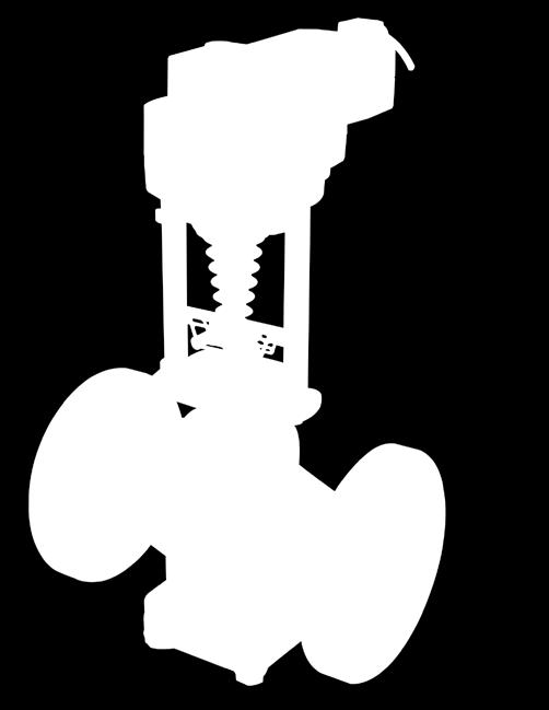
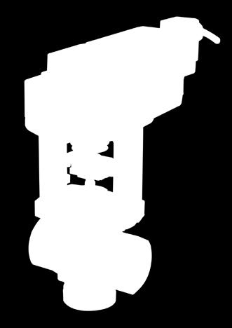
6 General Information - Globe Valves The New Globe Valve Actuators Based on the technology that has already proven itself in rotary actuators a million times over, Belimo is now bringing a new generation of globe valve actuators to the market to complete the comprehensive standarised actuator concept. To further enhance the field of application, the entire product range has been expanded to a power spectrum of 1000 to 4500N naturally to the usual Belimo quality standards. The compact design permits installation in stationary heating, ventilation and air conditioning systems where space is restricted. The new range is characterised by simple and intuitive handling, from mechanical connection to adjusting parameters. Throttling Valves and Mixing Valves Belimo globe valves have been designed for a long service life in closed-loop circuits carrying cold, warm or hot water. Internal thread or flanged end valves are available. The design of Belimo globe valves has been greatly improved in several important ways. Various optimised features have been incorporated with the aim of increasing their service life and reducing maintenance costs. The valves are always supplied as a turnkey functional solution, i.e. together with a suitable linear actuator. There are several alternative actuator types offering different actuating force ratings and emergency control functions. Component parts of the globe valve: H2..X-S and H3..X-S Valve stem Top cover Valve body Valve stem Top cover Valve body Plug Plug H2..X-S Component parts of the globe valve: H6..W-SP, H7..W-S (mixing) and H7..W-D (diverting) H3..X-S Valve stem Bonnet Valve body Valve seat Valve stem Bonnet Valve body Upper valve core Valve core Plug Top cover Lower valve core Gasket Gasket Bolt Bolt Pipe H6..W-SP Balancing Core Structure H7..W-S & H7..W-D 6 When valve is fully closed, differential pressure increases gradually. A small amount of water will leak into the seat through a tiny hole. This allows pressure within the seat to assimilate with the inlet pressure. Pressure load on seat will be minimised. Therefore, high close-off pressure can be achieved. Inlet pressure = A, outlet pressure = AB
 Newly developed secondary drive New, simplified")

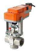
7 General Information Globe Valve Actuators Standard Globe Valve Actuator External adaptation push-button and LED status indicators IP54 connecting terminals with 1m cable Slot for hand crank Slot for auxiliary switch (optional) Newly developed secondary drive New, simplified connections for all Belimo valves Primary unit based on the tried and tested Belimo rotary actuators Temporary and permanent gear disengagement Newly designed bracket as part of the globe valve actuator A hexagon socket screw key for all installation and adjustment work (attached to the actuator) 7

8 H2..X-S Globe valves, 2-way, with internal thread For open and closed cold and warm water systems For modulating water-side control of air handling units and heating systems VAV reheat Type overview Type Kvs DN Stroke [m 3/h] [mm] [mm] H2015X-S H2020X-S H2025X-S H2032X-S H2040X-S H2050X-S rp s will be variant depends on actuator selection. Sv >50 >50 >50 >50 >50 >50 rps [kpa] / / 500 Technical data Functional data Materials Dimensions / Weights Flow media Temperature of medium Rated pressure Ps Flow characteristic Rangeability Sv Leakage rate Pipe connection Stroke Valve closing point Installation position Maintenance Body Valve cone Valve stem Valve seat Stem gland seal Dimensions and weights Cold and hot water, Refrigerant (R12, R22, R134a, R202), water with max. 50% volume of glycol, Hydrazine, Phosphate 0 C C 2500kPa (PN25) Control path A AB: equal percentage (to VDI/VDE 2173) n(gl) = 3, optimised in the opening range See «Type overview» Max. 0.02% of kvs value (DIN EN 1349 and DIN EN ) Internal thread to ISO 7/1 See «Type overview» Up ( ) Upright to horizontal (in relation to the stem) Maintenance-free Stainless steel SS304 Stainless steel SS304 Stainless steel SS304 Stainless steel SS304 EPDM O-Ring See «Dimensions and weights» 8
9 Globe valves, 2-way, with internal thread H2..X-S Safety notes This globe valve has been designed for use in stationary heating, ventilation and air-conditioning systems and is not allowed to be used outside the specified field of application, especially in aircraft or in any other airborne means of transport. It may only be installed by suitably trained personnel. All applicable legal or institutional installation regulations must be complied with. The valve does not contain any parts that can be replaced or repaired by the user. The valve is not allowed to be disposed of as household refuse. All locally valid regulations and requirements must be observed. The recognised rules should be applied when determining the flow characteristic of final controlling elements. Product features Mode of operation Flow characteristic Manual operation The globe valve is operated by an NV or SV series linear actuator. The linear actuators are controlled by a standard modulating or 3-point control system and move the cone of the valve, the throttling device, to the opening position dictated by the control signal. An equal-percentage flow characteristic is produced by profiling the valve cone. On the NV or SV linear actuator, the valve stem can be actuated manually using a hexagonal key. Installation notes Recommended mounting positions The globe valve may be mounted either vertically or horizontally. It is not permissible to mount the globe valve with the stem pointing downwards. Water quality requirements Maintenance Direction of flow The water quality requirements specified in VDI 2035 must be adhered to. Globe valves are relatively sensitive control devices. In order to ensure a long service life, it is advisable to fit strainers. The globe valves and linear actuators are maintenance-free. Before any kind of service work is carried out on actuator sets of this type, it is essential to isolate the linear actuator from the power supply (by unplugging the power lead). Any pumps in the part of the piping system concerned must also be switched off and the appropriate isolating fittings closed (allow everything to cool down first if necessary and reduce the pressure in the system to atmospheric). The system must not be returned to service until the globe valve and the linear actuator have been properly reassembled in accordance with the instructions and the pipework has been refilled in the proper manner. The direction of flow, specified by an arrow on the housing, is to be complied with, since otherwise the globe valve can be damaged. 9
![H2..X-S Globe valves, 2-way, with internal thread Dimensions and weights Dimensional drawings DN [mm] L1 [mm] H1 [mm] L3 [mm] 1) X [mm] 1) Y [mm] Weight [kg] 15 80 25.](/docs-images/77/75376275/images/10-0.jpg "5 38 296 100 1 20 80 28 40 299 100 1.1 25 100 32 44 303 100 1.5 32 103 35 47 306 100 1.8 40 122 40.5 52 311 100 2.4 50 138 47 65 318 100 3.4 1) Minimum distance with respect to the valve centre.")
10 H2..X-S Globe valves, 2-way, with internal thread Dimensions and weights Dimensional drawings DN [mm] L1 [mm] H1 [mm] L3 [mm] 1) X [mm] 1) Y [mm] Weight [kg] ) Minimum distance with respect to the valve centre. 2) The actuator dimensions can be found on the respective actuator data sheet. 10

11 H3..X-S Globe valves, 3-way, with internal thread For open and closed cold and hot water systems For modulating water-side control of air handling units and heating systems For converting and diverting application Type overview Type Kvs DN Stroke [m 3/h] [mm] [mm] H3015X-S H3020X-S H3025X-S H3032X-S H3040X-S H3050X-S rp s will be variant depends on actuator selection. Sv >50 >50 >50 >50 >50 >50 rps [kpa] / / 500 Technical data Functional data Materials Dimensions / Weights Flow media Temperature of medium Rated pressure Ps Flow characteristic Rangeability Sv Leakage rate Pipe connection Stroke Valve closing point Installation position Maintenance Body Valve cone Valve stem Valve seat Stem gland seal Dimensions and weights Cold and hot water, Refrigerant (R12, R22, R134a, R202), water with max. 50% volume of glycol, Hydrazine, Phosphate 0 C C 2500kPa (PN25) Control path A AB, B-AB: equal percentage (to VDI/VDE 2173) n(gl) = 3, optimised in the opening range See «Type overview» Max. 0.02% of kvs value on all path (DIN EN 1349 and DIN EN ) Internal thread to ISO 7/1 See «Type overview» Up ( ) Upright to horizontal (in relation to the stem) Maintenance-free Stainless steel SS304 Stainless steel SS304 Stainless steel SS304 Stainless steel SS304 Teflon See «Dimensions and weights» 11

12 H3..X-S Globe valves, 3-way, with internal thread Safety notes This globe valve has been designed for use in stationary heating, ventilation and air-conditioning systems and is not allowed to be used outside the specified field of application, especially in aircraft or in any other airborne means of transport. It may only be installed by suitably trained personnel. All applicable legal or institutional installation regulations must be complied with. The valve does not contain any parts that can be replaced or repaired by the user. The valve is not allowed to be disposed of as household refuse. All locally valid regulations and requirements must be observed. The recognised rules should be applied when determining the flow characteristic of final controlling elements. Product features Mode of operation Flow characteristic Manual operation The globe valve is operated by an NV or SV series linear actuator. The linear actuators are controlled by a standard modulating or 3-point control system and move the cone of the valve, the throttling device, to the opening position dictated by the control signal. An equal-percentage flow characteristic is produced by profiling the valve cone. The bypass exhibits a linear characteristic curve. On the NV or SV linear actuator, the valve stem can be actuated manually using a hexagonal key. Installation notes Recommended mounting positions The globe valve may be mounted either vertically or horizontally. It is not permissible to mount the globe valve with the stem pointing downwards. Water quality requirements Maintenance Direction of flow The water quality requirements specified in VDI 2035 must be adhered to. Globe valves are relatively sensitive control devices. In order to ensure a long service life, it is advisable to fit strainers. The globe valves and linear actuators are maintenance-free. Before any kind of service work is carried out on actuator sets of this type, it is essential to isolate the linear actuator from the power supply (by unplugging the power lead). Any pumps in the part of the piping system concerned must also be switched off and the appropriate isolating fittings closed (allow everything to cool down first if necessary and reduce the pressure in the system to atmospheric). The system must not be returned to service until the globe valve and the linear actuator have been properly reassembled in accordance with the instructions and the pipework has been refilled in the proper manner. The direction of flow, specified by an arrow on the housing, is to be complied with, since otherwise the globe valve can be damaged. 12
![Globe valves, 3-way, with internal thread H3..X-S Dimensions and weights Dimensional drawings DN [mm] L1 [mm] H1 [mm] L3 [mm] 1) X [mm] Y 1) [mm] Weight [kg] 15 80 25.5 49 296 100 0.](/docs-images/77/75376275/images/13-0.jpg "8 20 80 28 51 299 100 1.1 25 100 32 55 303 100 1.6 32 103 35 62 306 100 1.8 40 122 40.5 71 311 100 2.3 50 138 47 85 318 100 3.3 1) Minimum distance with respect to the valve centre.")
13 Globe valves, 3-way, with internal thread H3..X-S Dimensions and weights Dimensional drawings DN [mm] L1 [mm] H1 [mm] L3 [mm] 1) X [mm] Y 1) [mm] Weight [kg] ) Minimum distance with respect to the valve centre. 2) The actuator dimensions can be found on the respective actuator data sheet. 13

14 H6..W-SP Globe valves, 2-way, with flange PN16 For closed cold and hot water systems For modulating water-side control of air handling units and heating systems Type overview Type Kvs DN Stroke Sv rps [m 3/h] [mm] [mm] [kpa] H6065W-SP > H6080W-SP > H6100W-SP > H6125W-SP > H6150W-SP > H6200W-SP > H6250W-SP > Technical data Functional data Materials Dimensions / Weights Flow media Temperature of medium Rated pressure Ps Flow characteristic Rangeability Sv Leakage rate Pipe connection Stroke Valve closing point Installation position Maintenance Body Valve cone Valve stem Valve seat Stem gland seal Dimensions and weights Cold and hot water, Refrigerant (R12, R22, R134a, R202), water with max. 50% volume of glycol, Hydrazine, Phosphate 0 C C 1600kPa (PN16) Control path A AB: equal percentage (to VDI/VDE 2173) n(gl) = 3, optimised in the opening range See «Type overview» Max. 0.02% of kvs value (DIN EN 1349 and DIN EN ) Flange to ISO (PN16) See «Type overview» Up ( ) Upright to horizontal (in relation to the stem) Maintenance-free Ductile iron GGG40 Stainless steel SS304 Stainless steel SS304 Stainless steel SS304 Teflon See «Dimensions and weights» 14

15 Globe valves, 2-way, with flange PN16 H6..W-SP Safety notes This globe valve has been designed for use in stationary heating, ventilation and air-conditioning systems and is not allowed to be used outside the specified field of application, especially in aircraft or in any other airborne means of transport. It may only be installed by suitably trained personnel. All applicable legal or institutional installation regulations must be complied with. The valve does not contain any parts that can be replaced or repaired by the user. The valve is not allowed to be disposed of as household refuse. All locally valid regulations and requirements must be observed. The recognised rules should be applied when determining the flow characteristic of final controlling elements. Product features Mode of operation Flow characteristic Manual operation The globe valve is operated by an SV, EV or RV series linear actuator. The linear actuators are controlled by a standard modulating or 3-point control system and move the cone of the valve, the throttling device, to the opening position dictated by the control signal. An equal-percentage flow characteristic is produced by profiling the valve cone. On the SV, EV or RV linear actuator, the valve stem can be actuated manually using a hexagonal key. Installation notes Recommended mounting positions The globe valve may be mounted either vertically or horizontally. It is not permissible to mount the globe valve with the stem pointing downwards. Water quality requirements Maintenance Direction of flow The water quality requirements specified in VDI 2035 must be adhered to. Globe valves are relatively sensitive control devices. In order to ensure a long service life, it is advisable to fit strainers. The globe valves and linear actuators are maintenance-free. Before any kind of service work is carried out on actuator sets of this type, it is essential to isolate the linear actuator from the power supply (by unplugging the power lead). Any pumps in the part of the piping system concerned must also be switched off and the appropriate isolating fittings closed (allow everything to cool down first if necessary and reduce the pressure in the system to atmospheric). The system must not be returned to service until the globe valve and the linear actuator have been properly reassembled in accordance with the instructions and the pipework has been refilled in the proper manner. The direction of flow, specified by an arrow on the housing, is to be complied with, since otherwise the globe valve can be damaged. 15
![H6..W-SP Globe valves, 2-way, with flange PN16 Dimensions and weights Dimensional drawings DN [mm] B [mm] D [mm] D2 [mm] D4 [mm] K [mm] L1 [mm] L2 [mm] L3 [mm] H1 [mm] 2) X [mm] 2) Y [mm] Weight [kg]](/docs-images/77/75376275/images/16-0.jpg "65 22 185 4-18 118 145 290 145 115 105 376 665 18.5 80 22 200 8-18 132 160 310 155 130 118 502 665 25 100 23 220 8-18 156 180 350 175 150 135 519 665 35.")
16 H6..W-SP Globe valves, 2-way, with flange PN16 Dimensions and weights Dimensional drawings DN [mm] B [mm] D [mm] D2 [mm] D4 [mm] K [mm] L1 [mm] L2 [mm] L3 [mm] H1 [mm] 2) X [mm] 2) Y [mm] Weight [kg] ) Minimum distance with respect to the valve centre. 3) The actuator dimensions can be found on the respective actuator data sheet. 16
![H7..W-S Globe valves, 3-way, with flange PN16 For closed cold and hot water systems For modulating water-side control of air handling units and heating systems Type overview Type Kvs [m 3/h] DN [mm]](/docs-images/77/75376275/images/17-0.jpg "Stroke [mm] Sv rps [kpa] H7065W-S* 50 65 20 >50 450 H7080W-S 80 80 30 >50 270 / 350 H7100W-S 125 100 40 >50 200 / 300 H7125W-S 200 125 40 >50 150 / 200 H7150W-S 300 150 40 >50 100 / 150 H7200W-S 520")
17 H7..W-S Globe valves, 3-way, with flange PN16 For closed cold and hot water systems For modulating water-side control of air handling units and heating systems Type overview Type Kvs [m 3/h] DN [mm] Stroke [mm] Sv rps [kpa] H7065W-S* > H7080W-S > / 350 H7100W-S > / 300 H7125W-S > / 200 H7150W-S > / 150 H7200W-S > H7250W-S >50 80 rp s will be variant depends on actuator selection. *H7065W-S is available for diverting application. Technical data Functional data Materials Dimensions / Weights Flow media Temperature of medium Rated pressure Ps Flow characteristic Rangeability S v Leakage rate Pipe connection Stroke Valve closing point Installation position Maintenance Body Valve cone Valve stem Valve seat Stem gland seal Dimensions and weights Cold and hot water, Refrigerant (R12, R22, R134a, R202), water with max. 50% volume of glycol, Hydrazine, Phosphate 0 C C 1600kPa (PN16) Control path A AB, B-AB: equal percentage (to VDI/VDE 2173) n(gl) = 3, optimised in the opening range See «Type overview» Max. 0.02% of kvs value on all path (DIN EN 1349 and DIN EN ) Flange to ISO (PN16) See «Type overview» Up ( ) Upright to horizontal (in relation to the stem) Maintenance-free Ductile iron GGG40 Stainless steel SS304 Stainless steel SS304 Stainless steel SS304 Teflon See «Dimensions and weights» 17

18 H7..W-S Globe valves, 3-way, with flange PN16 Safety notes This globe valve has been designed for use in stationary heating, ventilation and air-conditioning systems and is not allowed to be used outside the specified field of application, especially in aircraft or in any other airborne means of transport. It may only be installed by suitably trained personnel. All applicable legal or institutional installation regulations must be complied with. The valve does not contain any parts that can be replaced or repaired by the user. The valve is not allowed to be disposed of as household refuse. All locally valid regulations and requirements must be observed. The recognised rules should be applied when determining the flow characteristic of final controlling elements. Product features Mode of operation Flow characteristic Manual operation The globe valve is operated by an SV, EV or RV series linear actuator. The linear actuators are controlled by a standard modulating or 3-point control system and move the cone of the valve, the throttling device, to the opening position dictated by the control signal. An equal-percentage flow characteristic is produced by profiling the valve cone. The bypass exhibits a linear characteristic curve. On the SV, EV or RV linear actuator, the valve stem can be actuated manually using a hexagonal key. Installation notes Recommended mounting positions The globe valve may be mounted either vertically or horizontally. It is not permissible to mount the globe valve with the stem pointing downwards. Water quality requirements Maintenance Direction of flow The water quality requirements specified in VDI 2035 must be adhered to. Globe valves are relatively sensitive control devices. In order to ensure a long service life, it is advisable to fit strainers. The globe valves and linear actuators are maintenance-free. Before any kind of service work is carried out on actuator sets of this type, it is essential to isolate the linear actuator from the power supply (by unplugging the power lead). Any pumps in the part of the piping system concerned must also be switched off and the appropriate isolating fittings closed (allow everything to cool down first if necessary and reduce the pressure in the system to atmospheric). The system must not be returned to service until the globe valve and the linear actuator have been properly reassembled in accordance with the instructions and the pipework has been refilled in the proper manner. The direction of flow, specified by an arrow on the housing, is to be complied with, since otherwise the globe valve can be damaged. 18 H7065W-S only

19 Globe valves, 3-way, with flange PN16 H7..W-S Dimensions and weights Dimensional drawings DN [mm] C [mm] D [mm] D2 [mm] D4 [mm] K [mm] L1 [mm] L2 [mm] L3 [mm] H1 [mm] X [mm] Y [mm] Weight [kg] ) The actuator dimensions can be found on the respective actuator data sheet. 19
20 H7..W-D Globe valves, 3-way, with flange PN16 For closed cold and hot water systems For modulating water-side control of air handling units and heating systems For diverting application only Type overview Type H7080W-D H7100W-D H7125W-D H7150W-D Kvs [m 3/h] DN [mm] Stroke [mm] rp will be variant depends on actuator selection. s Sv >50 >50 >50 >50 rps [kpa] 270 / / / / 150 Technical data Functional data Materials Dimensions / Weights Flow media Temperature of medium Rated pressure Ps Flow characteristic Rangeability S v Leakage rate Pipe connection Stroke Valve closing point Installation position Maintenance Body Valve cone Valve stem Valve seat Stem gland seal Dimensions and weights Cold and hot water, Refrigerant (R12, R22, R134a, R202), water with max. 50% volume of glycol, Hydrazine, Phosphate 0 C C 1600kPa (PN16) Control path AB-A, AB-B: equal percentage (to VDI/VDE 2173) n(gl) = 3, optimized in the opening range See «Type overview» Max. 0.02% of kvs value on all path (DIN EN 1349 and DIN EN ) Flange to ISO (PN16) See «Type overview» Up ( ) Upright to horizontal (in relation to the stem) Maintenance-free Ductile iron GGG40 Stainless steel SS304 Stainless steel SS304 Stainless steel SS304 Teflon See «Dimensions and weights» Safety notes Product features Mode of operation Flow characteristic Manual operation 20 This globe valve has been designed for use in stationary heating, ventilation and air-conditioning systems and is not allowed to be used outside the specified field of application, especially in aircraft or in any other airborne means of transport. It may only be installed by suitably trained personnel. All applicable legal or institutional installation regulations must be complied with. The valve does not contain any parts that can be replaced or repaired by the user. The valve is not allowed to be disposed of as household refuse. All locally valid regulations and requirements must be observed. The recognised rules should be applied when determining the flow characteristic of final controlling elements. The globe valve is operated by an EV or RV series linear actuator. The linear actuators are controlled by a standard modulating or 3-point control system and move the cone of the valve, the throttling device, to the opening position dictated by the control signal. An equal-percentage flow characteristic is produced by profiling the valve cone. The bypass exhibits a linear characteristic curve. On the EV or RV linear actuator, the valve stem can be actuated manually using a hexagonal key.

.")
21 Globe valves, 3-way, with flange PN16 H7..W-D Installation notes Recommended mounting positions The globe valve may be mounted either vertically or horizontally. It is not permissible to mount the globe valve with the stem pointing downwards. Water quality requirements Maintenance The water quality requirements specified in VDI 2035 must be adhered to. Globe valves are relatively sensitive control devices. In order to ensure a long service life, it is advisable to fit strainers. The globe valves and linear actuators are maintenance-free. Before any kind of service work is carried out on actuator sets of this type, it is essential to isolate the linear actuator from the power supply (by unplugging the power lead). Any pumps in the part of the piping system concerned must also be switched off and the appropriate isolating fittings closed (allow everything to cool down first if necessary and reduce the pressure in the system to atmospheric). The system must not be returned to service until the globe valve and the linear actuator have been properly reassembled in accordance with the instructions and the pipework has been refilled in the proper manner. Direction of flow The direction of flow, specified by an arrow on the housing, is to be complied with, since otherwise the globe valve can be damaged. Dimensions and weights Dimensional drawings DN [mm] C [mm] D [mm] D2 [mm] D4 [mm] K [mm] L1 [mm] L2 [mm] L3 H1 [mm] [mm] ) The actuator dimensions can be found on the respective actuator data sheet. X [mm] Y [mm] Weight [kg]
22 Globe Valves Dimension Size Overview Dimensions H2..X-S Globe valve 2-way series, PN25 Model Type DN Dimension[mm] In mm L1 L3 H1 H2 H Weight (kg) H2015X-S 1/ H2020X-S 3/ H2025X-S H2032X-S 1-1/ H2040X-S 1-1/ H2050X-S H3..X-S Globe valve 3-way series, PN25 Model Type DN Dimension[mm] In mm L1 L3 H1 H2 H Weight (kg) H3015X-S 1/ H H H2 H2 L H1 Rp L1 H3020X-S 3/ H3025X-S H1 H3032X-S 1-1/ H3040X-S 1-1/ L H3050X-S L1 Rp 22
23 Globe Valves Dimension Size Overview Dimensions B H6..W-SP Globe valve 2-way series, PN16 Model Type DN Dimension[mm] mm B D D2 D4 K L1 L2 L3 H1 H2 H H6065W-SP H6080W-SP H6100W-SP H6125W-SP H6150W-SP Weight (kg) H6200W-SP H6250W-SP K D2 L D4 D K H1 H2 D2 H L2 L1 B L D4 D H2 H1 H L2 L1 H7..W-S Globe valve 3-way series and H7..W-D (diverting), PN16 Model Type DN Dimension[mm] mm B D D2 D4 K L1 L2 L3 H1 H2 H H7065W-S H7080W-S H7080W-D H7100W-S H7100W-D H7125W-S H7125W-D H7150W-S H7150W-D Weight (kg) H7200W-S H7250W-S
24 NV24A-TPC Globe valve actuator for 2-way and 3-way globe valves Actuating force 1000N Nominal voltage AC/DC 24V Control: Open-close, 3-point Nominal stroke 20mm Technical data Electrical data Functional data Safety Weight Nominal voltage Nominal voltage frequency Nominal voltage range Power consumption in operation Power consumption in rest position Power consumption for wire sizing Connection supply / control Parallel operation Actuating force Manual override Nominal stroke Actuating time Sound power level motor max. Position indication Protection class IEC/EN Degree of protection IEC/EN EMC Certification IEC/EN Mode of operation Rated impulse voltage supply / control Control pollution degree Ambient temperature Non-operating temperature Ambient humidity Maintenance Weight approx. AC/DC 24V 50/60Hz AC V / DC V 1.5W 0.5W 3VA Terminals 4mm² and cable 1m, 3 x 0.75mm² Yes 1000N Gear disengagement with push-button, can be locked 20mm 150s/20mm 45dB(A) Mechanical mm stroke III Safety extra-low voltage IP54 CE in accordance with 2004/108/EC Certified to: IEC/EN and IEC/EN Type 1 0.8kV 3 0 C...50 C -40 C...80 C 95% r.h., non-condensing Maintenance-free 1.32kg Safety notes 24 This actuator has been designed for application in stationary heating, ventilation and airconditioning systems and is not allowed to be used outside the specified field of application, especially in aircraft or in any other airborne means of transport. Only authorised specialists may carry out installation. All applicable legal or institutional installation regulations must be complied with during installation. The switch for changing the direction of motion/the closing point may be adjusted only by authorised personnel. The direction of stroke is critical, particularly in connection with frost protection circuits. The device may only be opened at the manufacturer s site. It does not contain any parts that can be replaced or repaired by the user. The device contains electrical and electronic components and is not allowed to be disposed of as household refuse. All locally valid regulations and requirements must be observed.
25 Globe valve actuator, open-close, 3-point, AC/DC 24V, 1000N NV24A-TPC Product features Direct mounting Manual override High functional reliability Combination valve/actuator Position indication Home position Direction of stroke switch Simple direct mounting on the globe valve by means of form-fit hollow clamping jaws. The actuator can be rotated through 360 on the valve neck. Manual control with push-button possible - temporary, permanently. The gear is disengaged and the actuator decoupled for as long as the button is pressed / latched. The stroke can be adjusted by using a hexagon socket screw key (4mm), which is inserted into the top of the actuator. The stroke spindle extends when the key is rotated clockwise. The actuator is overload protected, requires no limit switches and automatically stops when the end stop is reached. Refer to the valve documentation for suitable valves, their permitted medium temperatures and closing pressures. The stroke is indicated mechanically on the bracket with tabs. The stroke range adjusts itself automatically during operation. Setting ex-works: Actuator spindle is retracted. When valve-actuator combinations are shipped, the direction of motion is set in accordance with the closing point of the valve. When actuated, the direction of stroke switch changes the running direction in normal operation. Accessories Electrical accessories Description Auxiliary switch Type S2A-H Electrical installation Notes Connection via safety isolating transformer. Parallel connection of other actuators possible. Direction of stroke switch factory setting: Actuator spindle retracted. Wiring diagrams AC/DC 24V, open-close (one-wire) AC/DC 24V, 3-point Cable colours: 1 = black 2 = red 3 = white Cable colours: 1 = black 2 = red 3 = white 25
26 NV24A-TPC Globe valve actuator, open-close, 3-point, AC/DC 24V, 1000N Indicators and operating controls (1) Direction of stroke switch Switching: Direction of stroke changes (4) Gear disengagement button Press button: Gear disengages, motor stops, manual override possible Release button: Gear engages, standard mode (10) Manual override Clockwise: Actuator spindle extends Counterclockwise: Actuator spindle retracts Dimensions [mm] Dimensional drawings 26
27 NV230A-TPC Globe valve actuator for 2-way and 3-way globe valves Actuating force 1000N Nominal voltage AC 230V Control: Open-close, 3-point Nominal stroke 20mm Technical data Electrical data Functional data Safety Weight Nominal voltage Nominal voltage frequency Nominal voltage range Power consumption in operation Power consumption in rest position Power consumption for wire sizing Connection supply / control Parallel operation Actuating force Manual override Nominal stroke Actuating time Sound power level motor max. Position indication Protection class IEC/EN Degree of protection IEC/EN EMC Certification IEC/EN Mode of operation Rated impulse voltage supply / control Control pollution degree Ambient temperature Non-operating temperature Ambient humidity Maintenance Weight approx. AC 230V 50/60Hz AC V 2W 1W 4.5VA Terminals 4mm² and cable 1m, 3 x 0.75mm² Yes 1000N Gear disengagement with push-button, can be locked 20mm 150s/20mm 45dB(A) Mechanical mm stroke II Protective insulated IP54 CE in accordance with 2004/108/EC Certified to: IEC/EN and IEC/EN Type 1 4kV 3 0 C...50 C -40 C...80 C 95% r.h., non-condensing Maintenance-free 1.32kg Safety notes This actuator has been designed for application in stationary heating, ventilation and airconditioning systems and is not allowed to be used outside the specified field of application, especially in aircraft or in any other airborne means of transport. Only authorised specialists may carry out installation. All applicable legal or institutional installation regulations must be complied with during installation. The switch for changing the direction of motion/the closing point may be adjusted only by authorised personnel. The direction of stroke is critical, particularly in connection with frost protection circuits. The device may only be opened at the manufacturer s site. It does not contain any parts that can be replaced or repaired by the user. The device contains electrical and electronic components and is not allowed to be disposed of as household refuse. All locally valid regulations and requirements must be observed. 27
28 NV230A-TPC Globe valve actuator, open-close, 3-point, AC 230V, 1000N Product features Direct mounting Manual override High functional reliability Combination valve/actuator Position indication Home position Direction of stroke switch Simple direct mounting on the globe valve by means of form-fit hollow clamping jaws. The actuator can be rotated through 360 on the valve neck. Manual control with push-button possible - temporary, permanently. The gear is disengaged and the actuator decoupled for as long as the button is pressed / latched. The stroke can be adjusted by using a hexagon socket screw key (4mm), which is inserted into the top of the actuator. The stroke spindle extends when the key is rotated clockwise. The actuator is overload protected, requires no limit switches and automatically stops when the end stop is reached. Refer to the valve documentation for suitable valves, their permitted medium temperatures and closing pressures. The stroke is indicated mechanically on the bracket with tabs. The stroke range adjusts itself automatically during operation. Setting ex-works: Actuator spindle is retracted. When valve-actuator combinations are shipped, the direction of motion is set in accordance with the closing point of the valve. When actuated, the direction of stroke switch changes the running direction in normal operation. Accessories Electrical accessories Description Auxiliary switch Type S2A-H Electrical installation Notes Parallel connection of other actuators possible. Direction of stroke switch factory setting: Actuator spindle retracted. Wiring diagrams AC 230V, open-close (one-wire) AC 230V, 3-point Cable colours: 1 = blue 2 = brown 3 = white Cable colours: 1 = blue 2 = brown 3 = white 28
29 Globe valve actuator, open-close, 3-point, AC 230V, 1000N NV230A-TPC Indicators and operating controls (1) Direction of stroke switch Switching: Direction of stroke changes (4) Gear disengagement button Press button: Gear disengages, motor stops, manual override possible Release button: Gear engages, standard mode (10) Manual override Clockwise: Actuator spindle extends Counterclockwise: Actuator spindle retracts Dimensions [mm] Dimensional drawings 29
30 NV24A-SZ-TPC Modulating globe valve actuator for 2-way and 3-way globe valves Actuating force 1000N Nominal voltage AC/DC 24V Control: modulating DC (0)0.5V...10V Nominal stroke 20mm Technical data Electrical data Functional data Safety Weight Nominal voltage Nominal voltage frequency Nominal voltage range Power consumption in operation Power consumption in rest position Power consumption for wire sizing Connection supply / control Parallel operation Actuating force Positioning signal Y Positioning signal Y note Operating range Y Position feedback U Position feedback U note Position accuracy Manual override Nominal stroke Actuating time Sound power level motor max. Position indication Protection class IEC/EN Degree of protection IEC/EN EMC Certification IEC/EN Mode of operation Rated impulse voltage supply / control Control pollution degree Ambient temperature Non-operating temperature Ambient humidity Maintenance Weight approx. AC/DC 24V 50/60Hz AC V / DC V 1.5W 0.5W 3VA Terminals 4mm² and cable 1m, 4 x 0.75mm² Yes 1000N DC V Input impedance 100kΩ DC V DC V max. 0.5mA 5% absolute Gear disengagement with push-button, can be locked 20mm 150s/20mm 45dB(A) Mechanical mm stroke III Safety extra-low voltage IP54 CE in accordance with 2004/108/EC Certified to: IEC/EN and IEC/EN Type 1 0.8kV 3 0 C...50 C -40 C...80 C 95% r.h., non-condensing Maintenance-free 1.34kg 30 Safety notes This actuator has been designed for application in stationary heating, ventilation and airconditioning systems and is not allowed to be used outside the specified field of application, especially in aircraft or in any other airborne means of transport. Only authorised specialists may carry out installation. All applicable legal or institutional installation regulations must be complied with during installation. The switch for changing the direction of motion/the closing point may be adjusted only by authorised personnel. The direction of stroke is critical, particularly in connection with frost protection circuits. The device may only be opened at the manufacturer s site. It does not contain any parts that can be replaced or repaired by the user.
31 Globe valve actuator, modulating, AC/DC 24V, 1000N NV24A-SZ-TPC Safety notes The device contains electrical and electronic components and is not allowed to be disposed of as household refuse. All locally valid regulations and requirements must be observed. Product features Principle of operation Direct mounting Manual override High functional reliability Combination valve/actuator Position indication Home position Direction of stroke switch Adaption of stroke range The actuator is connected with a standard modulating signal of DC V and travels to the position defined by the positioning signal. The measuring voltage U serves for the electrical display of the actuator position % and as slave control signal for other actuators. Simple direct mounting on the globe valve by means of form-fit hollow clamping jaws. The actuator can be rotated through 360 on the valve neck. Manual override with push-button possible - temporary, permanently. The gear is disengaged and the actuator decoupled for as long as the button is pressed / latched. The stroke can be adjusted by using a hexagon socket screw key (4mm), which is inserted into the top of the actuator. The stroke spindle extends when the key is rotated clockwise. The actuator is overload protected, requires no limit switches and automatically stops when the end stop is reached. Refer to the valve documentation for suitable valves, their permitted medium temperatures and closing pressures. The stroke is indicated mechanically on the bracket with tabs. The stroke range adjusts itself automatically during operation. Setting ex-works: Actuator spindle is retracted. When valve-actuator combinations are shipped, the direction of motion is set in accordance with the closing point of the valve. When actuated, the direction of stroke switch changes the running direction in normal operation. The first time the supply voltage is switched on, i.e. at the time of commissioning, the actuator carries out a stroke adaption, which is when the operating range and position feedback adjust themselves to the mechanical stroke. Manual triggering of the adaption can be carried out by pressing the Adaption button. The actuator then moves into the position defined by the positioning signal. Accessories Electrical accessories Description Auxiliary switch add-on, 2 x SPDT Type S2A-H Electrical installation Notes Connection via safety isolating transformer. Parallel connection of other actuators possible Direction of stroke switch factory setting: Actuator spindle retracted. Wiring diagrams AC/DC 24V, modulating DC (0) V DC (0) V Cable colours: 1 = black 2 = red 3 = white 5 = orange 31
32 NV24A-SZ-TPC Globe valve actuator, modulating, AC/DC 24V, 1000N Indicators and operating controls (1) Direction of stroke switch Switching: Direction of stroke changes (3) Push-button and LED display yellow Off: Standard mode Illuminated: Adaption procedure active Press button: Triggers stroke adaption, followed by standard mode (4) Gear disengagement button Press button: Gear disengages, motor stops, manual override possible Release button: Gear engages, standard mode (10) Manual override Clockwise: Actuator spindle extends Counterclockwise: Actuator spindle retracts Dimensions [mm] Dimensional drawings 32
33 NV24A-MP-TPC Communication-capable globe valve actuator for 2-way and 3-way globe valves Actuating force 1000N Nominal voltage AC/DC 24V Control modulating DC (0)0.5V...10V, variable Nominal stroke 20mm Technical data Electrical data Nominal voltage AC/DC 24V Nominal voltage frequency 50/60Hz Nominal voltage range AC V / DC V Power consumption in operation 3W Power consumption in rest position 1.5W Power consumption for wire sizing 4.5VA Connection supply / control Terminals 4mm² and cable 1m, 4 x 0.75mm² Parallel operation Yes Functional data Actuating force 1000N Positioning signal Y DC V Positioning signal Y note Input impedance 100kΩ Operating range Y DC V Operating range Y variable Start point DC V End point DC V Position feedback U DC V Position feedback U note max. 0.5mA Position feedback U variable Start point DC V End point DC V Position accuracy 5% absolute Manual override Gear disengagement with push-button, can be locked Nominal stroke 20mm Actuating time 150s/20mm Override control MAX (maximum position) 100% Override control MIN (minimum position) 0% Override control ZS (intermediate position, only AC) 50% Override control ZS variable ZS = MIN...MAX Sound power level motor max. 45dB(A) Sound power level motor note 90s running time Position indication Mechanical mm stroke Safety Protection class IEC/EN III Safety extra-low voltage Degree of protection IEC/EN IP54 EMC CE in accordance with 2004/108/EC Certification IEC/EN Certified to: IEC/EN and IEC/EN Mode of operation Type 1 Rated impulse voltage supply / control 0.8kV Weight Control pollution degree Ambient temperature Non-operating temperature Ambient humidity Maintenance Weight approx. 3 0 C...50 C -40 C...80 C 95% r.h., non-condensing Maintenance-free 1.36kg 33
34 NV24A-MP-TPC Globe valve actuator, communicative, modulating, AC/DC 24V, 1000N Safety notes This actuator has been designed for application in stationary heating, ventilation and airconditioning systems and is not allowed to be used outside the specified field of application, especially in aircraft or in any other airborne means of transport. Only authorised specialists may carry out installation. All applicable legal or institutional installation regulations must be complied with during installation. The switch for changing the direction of motion/the closing point may be adjusted only by authorised personnel. The direction of stroke is critical, particularly in connection with frost protection circuits. The device may only be opened at the manufacturer s site. It does not contain any parts that can be replaced or repaired by the user. The device contains electrical and electronic components and is not allowed to be disposed of as household refuse. All locally valid regulations and requirements must be observed. Product features Principle of operation Adjustable-parameter actuators Direct mounting Manual override High functional reliability Combination valve/actuator Position indication Home position Direction of stroke switch Adaption of stroke range The actuator is connected with a standard modulating signal of DC V and travels to the position defined by the positioning signal. The measuring voltage U serves for the electrical display of the actuator position % and as slave control signal for other actuators. The factory settings cover the most common applications. Input and output signals and other parameters can be altered with the PC-Tool MFT-P or with the service tool ZTH-GEN. Simple direct mounting on the globe valve by means of form-fit hollow clamping jaws. The actuator can be rotated through 360 on the valve neck. Manual override with push-button possible - temporary, permanently. The gear is disengaged and the actuator decoupled for as long as the button is pressed / latched. The stroke can be adjusted by using a hexagon socket screw key (4mm), which is inserted into the top of the actuator. The stroke spindle extends when the key is rotated clockwise. The actuator is overload protected, requires no limit switches and automatically stops when the end stop is reached. Refer to the valve documentation for suitable valves, their permitted medium temperatures and closing pressures. The stroke is indicated mechanically on the bracket with tabs. The stroke range adjusts itself automatically during operation. Setting ex-works: Actuator spindle is retracted. When valve-actuator combinations are shipped, the direction of motion is set in accordance with the closing point of the valve. When actuated, the direction of stroke switch changes the running direction in normal operation. The first time the supply voltage is switched on, i.e. at the time of commissioning, the actuator carries out a stroke adaption, which is when the operating range and position feedback adjust themselves to the mechanical stroke. Manual triggering of the adaption can be carried out by pressing the Adaption button or with the PC-Tool. The actuator then moves into the position defined by the positioning signal. Accessories Description Electrical accessories Service tools Auxiliary switch add-on, 2 x SPDT Manual parameterising device, for MF/MP/Modbus/LonWorks actuators and VAV-Control Belimo PC-Tool, software for adjustments and diagnostics Type S2A-H ZTH-GEN 34 MFT-P
35 Globe valve actuator, communicative, modulating, AC/DC 24V, 1000N NV24A-MP-TPC Electrical installation Notes Connection via safety isolating transformer. Parallel connection of other actuators possible. Direction of stroke switch factory setting: Actuator spindle retracted. Wiring diagrams AC/DC 24V, modulating Operation on the MP-Bus DC (0) V DC (0) V Cable colours: 1 = black 2 = red 3 = white 5 = orange Sensor MP Cable colours: 1 = black 2 = red 3 = white 5 = orange Functions Functions with basic values Override control with AC 24V with relay contacts Override control with AC 24V with rotary switch Y (DC V) Y (DC V) Remote control % Follow-up control (position-dependent) U DC V U DC V 35
36 NV24A-MP-TPC Globe valve actuator, communicative, modulating, AC/DC 24V, 1000N Functions Control with mA via external resistor mA U DC V The 500Ω resistor converts the mA current signal to a voltage signal DC V Functions for actuators with specific parameters Override control and limiting with AC 24V with relay contacts Y (DC V) Override control and limiting with AC 24V with rotary switch Y (DC V) 1) Caution: This function is guaranteed only if the start point of the operating range is defined as min. 0.6V. 36
37 Globe valve actuator, communicative, modulating, AC/DC 24V, 1000N NV24A-MP-TPC Functions AC 24V, 3-point Functions when operated on MP-Bus Connection on the MP-Bus Power topology Supply and communication in one and the same 3-wire cable no shielding or twisting required no terminating resistor required There are no restrictions for the network topology (star, ring, tree or mixed forms are permitted). Connection of active sensors Connection of external switching contact Supply AC/DC 24A Output signal DC V (max. DC V) Resolution 30mV Switching current 24V Start point of the operating range must be parameterised on the MP actuator as 0.6V Connection of passive sensors 1) Depending on the type 2) Resolution 1 Ohm 37
38 NV24A-MP-TPC Globe valve actuator, communicative, modulating, AC/DC 24V, 1000N Indicators and operating controls (1) Direction of stroke switch Switching: Direction of stroke changes (2) Push-button and LED display green Off: No power supply or malfunction Illuminated in green: In operation Press button: Triggers stroke adaption, followed by standard mode (3) Push-button and LED display yellow Off: Standard mode Flickering: MP communication active Illuminated: Adaption procedure active Blinking: Request for addressing from MP master Press button: Confirmation of addressing (4) Gear disengagement button Press button: Gear disengages, motor stops, manual override possible Release button: Gear engages, standard mode (5) Service plug For connecting the parameterisation and service tools (10) Manual override Clockwise: Actuator spindle extends Counterclockwise: Actuator spindle retracts LED displays (2, green) and (3, yellow) green: Off; yellow: Illuminated; Check the supply connections. The phases may have been switched. Dimensions [mm] Dimensional drawings 38
39 SV24A-TPC Globe valve actuator for 2-way and 3-way globe valves Actuating force 1500N Nominal voltage AC/DC 24V Control: Open-close, 3-point Nominal stroke 20mm Technical data Electrical data Functional data Safety Weight Nominal voltage Nominal voltage frequency Nominal voltage range Power consumption in operation Power consumption in rest position Power consumption for wire sizing Connection supply / control Parallel operation Actuating force Manual override Nominal stroke Actuating time Sound power level motor max. Position indication Protection class IEC/EN Degree of protection IEC/EN EMC Certification IEC/EN Mode of operation Rated impulse voltage supply / control Control pollution degree Ambient temperature Non-operating temperature Ambient humidity Maintenance Weight approx. AC/DC 24V 50/60Hz AC V / DC V 3W 0.5W 5VA Terminals 4mm² and cable 1m, 3 x 0.75mm² Yes 1500N Gear disengagement with push-button, can be locked 20mm 150s/20mm 35dB(A) Mechanical mm stroke III Safety extra-low voltage IP54 CE in accordance with 2004/108/EC Certified to: IEC/EN and IEC/EN Type 1 0.8kV 3 0 C...50 C -40 C...80 C 95% r.h., non-condensing Maintenance-free 1.34kg Safety notes This actuator has been designed for application in stationary heating, ventilation and airconditioning systems and is not allowed to be used outside the specified field of application, especially in aircraft or in any other airborne means of transport. Only authorised specialists may carry out installation. All applicable legal or institutional installation regulations must be complied with during installation. The switch for changing the direction of motion/the closing point may be adjusted only by authorised personnel. The direction of stroke is critical, particularly in connection with frost protection circuits. The device may only be opened at the manufacturer s site. It does not contain any parts that can be replaced or repaired by the user. The device contains electrical and electronic components and is not allowed to be disposed of as household refuse. All locally valid regulations and requirements must be observed. 39
40 SV24A-TPC Globe valve actuator, open-close, 3-point, AC/DC 24V, 1500N Product features Direct mounting Manual override High functional reliability Combination valve/actuator Position indication Home position Direction of stroke switch Simple direct mounting on the globe valve by means of form-fit hollow clamping jaws. The actuator can be rotated through 360 on the valve neck. Manual control with push-button possible - temporary, permanently. The gear is disengaged and the actuator decoupled for as long as the button is pressed / latched. The stroke can be adjusted by using a hexagon socket screw key (4mm), which is inserted into the top of the actuator. The stroke spindle extends when the key is rotated clockwise. The actuator is overload protected, requires no limit switches and automatically stops when the end stop is reached. Refer to the valve documentation for suitable valves, their permitted medium temperatures and closing pressures. The stroke is indicated mechanically on the bracket with tabs. The stroke range adjusts itself automatically during operation. Setting ex-works: Actuator spindle is retracted. When valve-actuator combinations are shipped, the direction of motion is set in accordance with the closing point of the valve. When actuated, the direction of stroke switch changes the running direction in normal operation. Accessories Electrical accessories Description Auxiliary switch Type S2A-H Electrical installation Notes Connection via safety isolating transformer. Parallel connection of other actuators possible. Direction of stroke switch factory setting: Actuator spindle retracted. Wiring diagrams AC/DC 24V, open-close (one-wire) AC/DC 24V, 3-point Cable colours: 1 = black 2 = red 3 = white Cable colours: 1 = black 2 = red 3 = white 40
41 Globe valve actuator, open-close, 3-point, AC/DC 24V, 1500N SV24A-TPC Indicators and operating controls (1) Direction of stroke switch Switching: Direction of stroke changes (4) Gear disengagement button Press button: Gear disengages, motor stops, manual override possible Release button: Gear engages, standard mode (10) Manual override Clockwise: Actuator spindle extends Counterclockwise: Actuator spindle retracts Dimensions [mm] Dimensional drawings 41
42 SV230A-TPC Globe valve actuator for 2-way and 3-way globe valves Actuating force 1500N Nominal voltage AC 230V Control: Open-close, 3-point Nominal stroke 20mm Technical data Electrical data Functional data Safety Weight Nominal voltage Nominal voltage frequency Nominal voltage range Power consumption in operation Power consumption in rest position Power consumption for wire sizing Connection supply / control Parallel operation Actuating force Manual override Nominal stroke Actuating time Sound power level motor max. Position indication Protection class IEC/EN Degree of protection IEC/EN EMC Certification IEC/EN Mode of operation Rated impulse voltage supply / control Control pollution degree Ambient temperature Non-operating temperature Ambient humidity Maintenance Weight approx. AC 230V 50/60Hz AC V 3.5W 1W 6.5VA Terminals 4mm² and cable 1m, 3 x 0.75mm² Yes 1500N Gear disengagement with push-button, can be locked 20mm 150s/20mm 35dB(A) Mechanical mm stroke II Protective insulated IP54 CE in accordance with 2004/108/EC Certified to: IEC/EN and IEC/EN Type 1 4kV 3 0 C...50 C -40 C...80 C 95% r.h., non-condensing Maintenance-free 1.4kg 42 Safety notes This actuator has been designed for application in stationary heating, ventilation and airconditioning systems and is not allowed to be used outside the specified field of application, especially in aircraft or in any other airborne means of transport. Only authorised specialists may carry out installation. All applicable legal or institutional installation regulations must be complied with during installation. The switch for changing the direction of motion/the closing point may be adjusted only by authorised personnel. The direction of stroke is critical, particularly in connection with frost protection circuits. The device may only be opened at the manufacturer s site. It does not contain any parts that can be replaced or repaired by the user. The device contains electrical and electronic components and is not allowed to be disposed of as household refuse. All locally valid regulations and requirements must be observed.
43 Globe valve actuator, open-close, 3-point, AC 230V, 1500N SV230A-TPC Product features Direct mounting Manual override High functional reliability Combination valve/actuator Position indication Home position Direction of stroke switch Simple direct mounting on the globe valve by means of form-fit hollow clamping jaws. The actuator can be rotated through 360 on the valve neck. Manual control with push-button possible - temporary, permanently. The gear is disengaged and the actuator decoupled for as long as the button is pressed / latched. The stroke can be adjusted by using a hexagon socket screw key (4mm), which is inserted into the top of the actuator. The stroke spindle extends when the key is rotated clockwise. The actuator is overload protected, requires no limit switches and automatically stops when the end stop is reached. Refer to the valve documentation for suitable valves, their permitted medium temperatures and closing pressures. The stroke is indicated mechanically on the bracket with tabs. The stroke range adjusts itself automatically during operation. Setting ex-works: Actuator spindle is retracted. When valve-actuator combinations are shipped, the direction of motion is set in accordance with the closing point of the valve. When actuated, the direction of stroke switch changes the running direction in normal operation. Accessories Electrical accessories Description Auxiliary switch Type S2A-H Electrical installation Notes Parallel connection of other actuators possible. Direction of stroke switch factory setting: Actuator spindle retracted. Wiring diagrams AC 230V, open-close (one-wire) AC 230V, 3-point Cable colours: 1 = blue 2 = brown 3 = white Cable colours: 1 = blue 2 = brown 3 = white 43
44 SV230A-TPC Globe valve actuator, open-close, 3-point, AC 230V, 1500N Indicators and operating controls (1) Direction of stroke switch Switching: Direction of stroke changes (4) Gear disengagement button Press button: Gear disengages, motor stops, manual override possible Release button: Gear engages, standard mode (10) Manual override Clockwise: Actuator spindle extends Counterclockwise: Actuator spindle retracts Dimensions [mm] Dimensional drawings 44
45 SV24A-SZ-TPC Modulating globe valve actuator for 2-way and 3-way globe valves Actuating force 1500N Nominal voltage AC/DC 24V Control: modulating DC (0)0.5V...10V Nominal stroke 20mm Technical data Electrical data Functional data Safety Weight Nominal voltage Nominal voltage frequency Nominal voltage range Power consumption in operation Power consumption in rest position Power consumption for wire sizing Connection supply / control Parallel operation Actuating force Positioning signal Y Positioning signal Y note Operating range Y Position feedback U Position feedback U note Position accuracy Manual override Nominal stroke Actuating time Sound power level motor max. Position indication Protection class IEC/EN Degree of protection IEC/EN EMC Certification IEC/EN Mode of operation Rated impulse voltage supply / control Control pollution degree Ambient temperature Non-operating temperature Ambient humidity Maintenance Weight approx. AC/DC 24V 50/60Hz AC V / DC V 2W 1.5W 3.5VA Terminals 4mm² and cable 1m, 4 x 0.75mm² Yes 1500N DC V Input impedance 100kΩ DC V DC V max. 0.5mA 5% absolute Gear disengagement with push-button, can be locked 20mm 150s/20mm 35dB(A) Mechanical mm stroke III Safety extra-low voltage IP54 CE in accordance with 2004/108/EC Certified to: IEC/EN and IEC/EN Type 1 0.8kV 3 0 C...50 C -40 C...80 C 95% r.h., non-condensing Maintenance-free 1.39kg Safety notes This actuator has been designed for application in stationary heating, ventilation and airconditioning systems and is not allowed to be used outside the specified field of application, especially in aircraft or in any other airborne means of transport. Only authorised specialists may carry out installation. All applicable legal or institutional installation regulations must be complied with during installation. The switch for changing the direction of motion/the closing point may be adjusted only by authorised personnel. The direction of stroke is critical, particularly in connection with frost protection circuits. The device may only be opened at the manufacturer s site. It does not contain any parts that can be replaced or repaired by the user. 45
46 SV24A-SZ-TPC Globe valve actuator, modulating, AC/DC 24V, 1500N Safety notes The device contains electrical and electronic components and is not allowed to be disposed of as household refuse. All locally valid regulations and requirements must be observed. Product features Principle of operation Direct mounting Manual override High functional reliability Combination valve/actuator Position indication Home position Direction of stroke switch Adaption of stroke range The actuator is connected with a standard modulating signal of DC V and travels to the position defined by the positioning signal. The measuring voltage U serves for the electrical display of the actuator position % and as slave control signal for other actuators. Simple direct mounting on the globe valve by means of form-fit hollow clamping jaws. The actuator can be rotated through 360 on the valve neck. Manual override with push-button possible - temporary, permanently. The gear is disengaged and the actuator decoupled for as long as the button is pressed / latched. The stroke can be adjusted by using a hexagon socket screw key (4mm), which is inserted into the top of the actuator. The stroke spindle extends when the key is rotated clockwise. The actuator is overload protected, requires no limit switches and automatically stops when the end stop is reached. Refer to the valve documentation for suitable valves, their permitted medium temperatures and closing pressures. The stroke is indicated mechanically on the bracket with tabs. The stroke range adjusts itself automatically during operation. Setting ex-works: Actuator spindle is retracted. When valve-actuator combinations are shipped, the direction of motion is set in accordance with the closing point of the valve. When actuated, the direction of stroke switch changes the running direction in normal operation. The first time the supply voltage is switched on, i.e. at the time of commissioning, the actuator carries out a stroke adaption, which is when the operating range and position feedback adjust themselves to the mechanical stroke. Manual triggering of the adaption can be carried out by pressing the Adaption button. The actuator then moves into the position defined by the positioning signal. Accessories Electrical accessories Description Auxiliary switch add-on, 2 x SPDT Type S2A-H Electrical installation Notes Connection via safety isolating transformer. Parallel connection of other actuators possible Direction of stroke switch factory setting: Actuator spindle retracted. Wiring diagrams AC/DC 24V, modulating DC (0) V DC (0) V 46 Cable colours: 1 = black 2 = red 3 = white 5 = orange
47 Globe valve actuator, modulating, AC/DC 24V, 1000N SV24A-SZ-TPC Indicators and operating controls (1) Direction of stroke switch Switching: Direction of stroke changes (2) Push-button and LED display green Off: No power supply or malfunction Illuminated: In operation Press button: Triggers stroke adaption, followed by standard mode (3) LED display yellow Off: Standard mode Illuminated: Adaption procedure active (4) Gear disengagement button Press button: Gear disengages, motor stops, manual override possible Release button: Gear engages, standard mode (5) Service plug No function (10) Manual override Clockwise: Actuator spindle extends Counterclockwise: Actuator spindle retracts Dimensions [mm] Dimensional drawings 47
48 SV24A-MP-TPC Communication-capable globe valve actuator for 2-way and 3-way globe valves Actuating force 1500N Nominal voltage AC/DC 24V Control modulating DC (0)0.5V...10V, variable Nominal stroke 20mm Technical data Electrical data Nominal voltage AC/DC 24V Nominal voltage frequency 50/60Hz Nominal voltage range AC V / DC V Power consumption in operation 2W Power consumption in rest position 1.5W Power consumption for wire sizing 3.5VA Connection supply / control Terminals 4mm² and cable 1m, 4 x 0.75mm² Functional data Parallel operation Actuating force Yes 1500N Positioning signal Y DC V Positioning signal Y note Input impedance 100kΩ Operating range Y DC V Operating range Y variable Start point DC V End point DC V Position feedback U DC V Position feedback U note max. 0.5mA Position feedback U variable Start point DC V End point DC V Position accuracy 5% absolute Manual override Gear disengagement with push-button, can be locked Nominal stroke 20mm Actuating time 150s/20mm Override control MAX (maximum position) 100% Override control MIN (minimum position) 0% Override control ZS (intermediate position, only AC) 50% Override control ZS variable ZS = MIN...MAX Sound power level motor max. 35dB(A) Sound power level motor note 90s running time Position indication Mechanical mm stroke Safety Protection class IEC/EN III Safety extra-low voltage Degree of protection IEC/EN IP54 EMC CE in accordance with 2004/108/EC Certification IEC/EN Certified to: IEC/EN and IEC/EN Mode of operation Type 1 Rated impulse voltage supply / control 0.8kV 48 Weight Control pollution degree Ambient temperature Non-operating temperature Ambient humidity Maintenance Weight approx. 3 0 C...50 C -40 C...80 C 95% r.h., non-condensing Maintenance-free 1.39kg
49 Globe valve actuator, communicative, modulating, AC/DC 24V, 1500N SV24A-MP-TPC Safety notes This actuator has been designed for application in stationary heating, ventilation and airconditioning systems and is not allowed to be used outside the specified field of application, especially in aircraft or in any other airborne means of transport. Only authorised specialists may carry out installation. All applicable legal or institutional installation regulations must be complied with during installation. The switch for changing the direction of motion/the closing point may be adjusted only by authorised personnel. The direction of stroke is critical, particularly in connection with frost protection circuits. The device may only be opened at the manufacturer s site. It does not contain any parts that can be replaced or repaired by the user. The device contains electrical and electronic components and is not allowed to be disposed of as household refuse. All locally valid regulations and requirements must be observed. Product features Principle of operation Adjustable-parameter actuators Direct mounting Manual override High functional reliability Combination valve/actuator Position indication Home position Direction of stroke switch Adaption of stroke range The actuator is connected with a standard modulating signal of DC V and travels to the position defined by the positioning signal. The measuring voltage U serves for the electrical display of the actuator position % and as slave control signal for other actuators. The factory settings cover the most common applications. Input and output signals and other parameters can be altered with the PC-Tool MFT-P or with the service tool ZTH-GEN. Simple direct mounting on the globe valve by means of form-fit hollow clamping jaws. The actuator can be rotated through 360 on the valve neck. Manual override with push-button possible - temporary, permanently. The gear is disengaged and the actuator decoupled for as long as the button is pressed / latched. The stroke can be adjusted by using a hexagon socket screw key (4mm), which is inserted into the top of the actuator. The stroke spindle extends when the key is rotated clockwise. The actuator is overload protected, requires no limit switches and automatically stops when the end stop is reached. Refer to the valve documentation for suitable valves, their permitted medium temperatures and closing pressures. The stroke is indicated mechanically on the bracket with tabs. The stroke range adjusts itself automatically during operation. Setting ex-works: Actuator spindle is retracted. When valve-actuator combinations are shipped, the direction of motion is set in accordance with the closing point of the valve. When actuated, the direction of stroke switch changes the running direction in normal operation. The first time the supply voltage is switched on, i.e. at the time of commissioning, the actuator carries out a stroke adaption, which is when the operating range and position feedback adjust themselves to the mechanical stroke. Manual triggering of the adaption can be carried out by pressing the Adaption button or with the PC-Tool. The actuator then moves into the position defined by the positioning signal. Accessories Electrical accessories Service tools Description Auxiliary switch add-on, 2 x SPDT Manual parameterising device, for MF/MP/Modbus/LonWorks actuators and VAV-Control Belimo PC-Tool, software for adjustments and diagnostics Type S2A-H ZTH-GEN MFT-P 49
50 SV24A-MP-TPC Globe valve actuator, communicative, modulating, AC/DC 24V, 1500N Electrical installation Notes Connection via safety isolating transformer. Parallel connection of other actuators possible. Direction of stroke switch factory setting: Actuator spindle retracted. Wiring diagrams AC/DC 24V, modulating Operation on the MP-Bus DC (0) V DC (0) V Sensor MP Cable colours: 1 = black 2 = red 3 = white 5 = orange Cable colours: 1 = black 2 = red 3 = white 5 = orange Functions Functions with basic values Override control with AC 24V with relay contacts Override control with AC 24V with rotary switch Y (DC V) Y (DC V) Remote control % Follow-up control (position-dependent) U DC V U DC V 50
51 Globe valve actuator, communicative, modulating, AC/DC 24V, 1500N SV24A-MP-TPC Functions Control with mA via external resistor mA U DC V The 500Ω resistor converts the mA current signal to a voltage signal DC V Functions for actuators with specific parameters Override control and limiting with AC 24V with relay contacts Y (DC V) Override control and limiting with AC 24V with rotary switch Y (DC V) 1) Caution: This function is guaranteed only if the start point of the operating range is defined as min. 0.6V. 51
52 SV24A-MP-TPC Globe valve actuator, communicative, modulating, AC/DC 24V, 1500N Functions AC 24V, 3-point Functions when operated on MP-Bus Connection on the MP-Bus Power topology Supply and communication in one and the same 3-wire cable no shielding or twisting required no terminating resistor required There are no restrictions for the network topology (star, ring, tree or mixed forms are permitted). Connection of active sensors Connection of external switching contact Supply AC/DC 24A Output signal DC V (max. DC V) Resolution 30mV Switching current 24V Start point of the operating range must be parameterised on the MP actuator as 0.6V Connection of passive sensors 52 1) Depending on the type 2) Resolution 1 Ohm
53 Globe valve actuator, communicative, modulating, AC/DC 24V, 1500N SV24A-MP-TPC Indicators and operating controls (1) Direction of stroke switch Switching: Direction of stroke changes (2) Push-button and LED display green Off: No power supply or malfunction Illuminated in green: In operation Press button: Triggers stroke adaption, followed by standard mode (3) Push-button and LED display yellow Off: Standard mode Flickering: MP communication active Illuminated: Adaption procedure active Blinking: Request for addressing from MP master Press button: Confirmation of addressing (4) Gear disengagement button Press button: Gear disengages, motor stops, manual override possible Release button: Gear engages, standard mode (5) Service plug For connecting the parameterisation and service tools (10) Manual override Clockwise: Actuator spindle extends Counterclockwise: Actuator spindle retracts LED displays (2, green) and (3, yellow) green: Off; yellow: Illuminated; Check the supply connections. The phases may have been switched. Dimensions [mm] Dimensional drawings 53
54 EV24A-TPC Globe valve actuator for 2-way and 3-way globe valves Actuating force 2500N Nominal voltage AC/DC 24V Control: Open-close, 3-point Nominal stroke 40mm Technical data Electrical data Functional data Safety Weight Nominal voltage Nominal voltage frequency Nominal voltage range Power consumption in operation Power consumption in rest position Power consumption for wire sizing Connection supply / control Parallel operation Actuating force Manual override Nominal stroke Actuating time Sound power level motor max. Position indication Protection class IEC/EN Degree of protection IEC/EN EMC Certification IEC/EN Mode of operation Rated impulse voltage supply / control Control pollution degree Ambient temperature Non-operating temperature Ambient humidity Maintenance Weight approx. AC/DC 24V 50/60Hz AC V / DC V 2.5W 0.5W 4.5VA Terminals 4mm² and cable 1m, 3 x 0.75mm² Yes 2500N Gear disengagement with push-button, can be locked 40mm 150s/40mm 55dB(A) Mechanical mm stroke III Safety extra-low voltage IP54 CE in accordance with 2004/108/EC Certified to: IEC/EN and IEC/EN Type 1 0.8kV 3 0 C...50 C -40 C...80 C 95% r.h., non-condensing Maintenance-free 4.22kg Safety notes 54 This actuator has been designed for application in stationary heating, ventilation and airconditioning systems and is not allowed to be used outside the specified field of application, especially in aircraft or in any other airborne means of transport. Only authorised specialists may carry out installation. All applicable legal or institutional installation regulations must be complied with during installation. The switch for changing the direction of motion/the closing point may be adjusted only by authorised personnel. The direction of stroke is critical, particularly in connection with frost protection circuits. The device may only be opened at the manufacturer s site. It does not contain any parts that can be replaced or repaired by the user. The device contains electrical and electronic components and is not allowed to be disposed of as household refuse. All locally valid regulations and requirements must be observed.
55 Globe valve actuator, open-close, 3-point, AC/DC 24V, 2500N EV24A-TPC Product features Direct mounting Manual override High functional reliability Combination valve/actuator Position indication Home position Direction of stroke switch Simple direct mounting on the globe valve by means of form-fit hollow clamping jaws. The actuator can be rotated through 360 on the valve neck. Manual override with push-button possible - temporary, permanently. The gear is disengaged and the actuator decoupled for as long as the button is pressed / engaged. The stroke can be adjusted by using a hexagon socket screw key (5mm), which is inserted into the top of the actuator. The stroke spindle extends when the key is rotated clockwise. The actuator is overload protected, requires no limit switches and automatically stops when the end stop is reached. Refer to the valve documentation for suitable valves, their permitted medium temperatures and closing pressures. The stroke is indicated mechanically on the bracket with tabs. The stroke range adjusts itself automatically during operation. Setting ex-works: Actuator spindle is retracted. When valve-actuator combinations are shipped, the direction of motion is set in accordance with the closing point of the valve. When actuated, the direction of stroke switch changes the running direction in normal operation. Accessories Electrical accessories Description Auxiliary switch Type S2A-H Electrical installation Notes Connection via safety isolating transformer. Parallel connection of other actuators possible. Direction of stroke switch factory setting: Actuator spindle retracted. Wiring diagrams AC/DC 24V, open-close (one-wire) AC/DC 24V, 3-point Cable colours: 1 = black 2 = red 3 = white Cable colours: 1 = black 2 = red 3 = white 55
56 EV24A-TPC Globe valve actuator, open-close, 3-point, AC/DC 24V, 2500N Indicators and operating controls (1) Direction of stroke switch Switching: Direction of stroke changes (4) Gear disengagement button Press button: Gear disengages, motor stops, manual override possible Release button: Gear engages, standard mode (10) Manual override Clockwise: Actuator spindle extends Counterclockwise: Actuator spindle retracts Dimensions [mm] Dimensional drawings 56
57 EV230A-TPC Globe valve actuator for 2-way and 3-way globe valves Actuating force 2500N Nominal voltage AC 230V Control: Open-close, 3-point Nominal stroke 40mm Technical data Electrical data Functional data Safety Weight Nominal voltage Nominal voltage frequency Nominal voltage range Power consumption in operation Power consumption in rest position Power consumption for wire sizing Connection supply / control Parallel operation Actuating force Manual override Nominal stroke Actuating time Sound power level motor max. Position indication Protection class IEC/EN Degree of protection IEC/EN EMC Certification IEC/EN Mode of operation Rated impulse voltage supply / control Control pollution degree Ambient temperature Non-operating temperature Ambient humidity Maintenance Weight approx. AC 230V 50/60Hz AC V 5.5W 1W 9.5VA Terminals 4mm² and cable 1m, 3 x 0.75mm² Yes 2500N Gear disengagement with push-button, can be locked 40mm 150s/40mm 55dB(A) Mechanical mm stroke II Protective insulated IP54 CE in accordance with 2004/108/EC Certified to: IEC/EN and IEC/EN Type 1 4kV 3 0 C...50 C -40 C...80 C 95% r.h., non-condensing Maintenance-free 4.25kg Safety notes This actuator has been designed for application in stationary heating, ventilation and airconditioning systems and is not allowed to be used outside the specified field of application, especially in aircraft or in any other airborne means of transport. Only authorised specialists may carry out installation. All applicable legal or institutional installation regulations must be complied with during installation. The switch for changing the direction of motion/the closing point may be adjusted only by authorised personnel. The direction of stroke is critical, particularly in connection with frost protection circuits. The device may only be opened at the manufacturer s site. It does not contain any parts that can be replaced or repaired by the user. The device contains electrical and electronic components and is not allowed to be disposed of as household refuse. All locally valid regulations and requirements must be observed. 57
58 EV230A-TPC Globe valve actuator, open-close, 3-point, AC 230V, 2500N Product features Direct mounting Manual override High functional reliability Combination valve/actuator Position indication Home position Direction of stroke switch Simple direct mounting on the globe valve by means of form-fit hollow clamping jaws. The actuator can be rotated through 360 on the valve neck. Manual override with push-button possible - temporary, permanently. The gear is disengaged and the actuator decoupled for as long as the button is pressed / engaged. The stroke can be adjusted by using a hexagon socket screw key (5mm), which is inserted into the top of the actuator. The stroke spindle extends when the key is rotated clockwise. The actuator is overload protected, requires no limit switches and automatically stops when the end stop is reached. Refer to the valve documentation for suitable valves, their permitted medium temperatures and closing pressures. The stroke is indicated mechanically on the bracket with tabs. The stroke range adjusts itself automatically during operation. Setting ex-works: Actuator spindle is retracted. When valve-actuator combinations are shipped, the direction of motion is set in accordance with the closing point of the valve. When actuated, the direction of stroke switch changes the running direction in normal operation. Accessories Electrical accessories Description Auxiliary switch Type S2A-H Electrical installation Notes Parallel connection of other actuators possible. Direction of stroke switch factory setting: Actuator spindle retracted. Wiring diagrams AC 230V, open-close (one-wire) AC 230V, 3-point Cable colours: 1 = blue 2 = brown 3 = white Cable colours: 1 = blue 2 = brown 3 = white 58
59 Globe valve actuator, open-close, 3-point, AC 230V, 2500N EV230A-TPC Indicators and operating controls (1) Direction of stroke switch Switching: Direction of stroke changes (4) Gear disengagement button Press button: Gear disengages, motor stops, manual override possible Release button: Gear engages, standard mode (10) Manual override Clockwise: Actuator spindle extends Counterclockwise: Actuator spindle retracts Dimensions [mm] Dimensional drawings 59
60 EV24A-SZ-TPC Modulating globe valve actuator for 2-way and 3-way globe valves Actuating force 2500N Nominal voltage AC/DC 24V Control: modulating DC (0)0.5V...10V Nominal stroke 40mm Technical data Electrical data Functional data Safety Weight Nominal voltage Nominal voltage frequency Nominal voltage range Power consumption in operation Power consumption in rest position Power consumption for wire sizing Connection supply / control Parallel operation Actuating force Positioning signal Y Positioning signal Y note Operating range Y Position feedback U Position feedback U note Position accuracy Manual override Nominal stroke Actuating time Sound power level motor max. Position indication Protection class IEC/EN Degree of protection IEC/EN EMC Certification IEC/EN Mode of operation Rated impulse voltage supply / control Control pollution degree Ambient temperature Non-operating temperature Ambient humidity Maintenance Weight approx. AC/DC 24V 50/60Hz AC V / DC V 4W 1.5W 6VA Terminals 4mm² and cable 1m, 4 x 0.75mm² Yes 2500N DC V Input impedance 100kΩ DC V DC V max. 0.5mA 5% absolute Gear disengagement with push-button, can be locked 40mm 150s/40mm 55dB(A) Mechanical mm stroke III Safety extra-low voltage IP54 CE in accordance with 2004/108/EC Certified to: IEC/EN and IEC/EN Type 1 0.8kV 3 0 C...50 C -40 C...80 C 95% r.h., non-condensing Maintenance-free 4.32kg 60 Safety notes This actuator has been designed for application in stationary heating, ventilation and airconditioning systems and is not allowed to be used outside the specified field of application, especially in aircraft or in any other airborne means of transport. Only authorised specialists may carry out installation. All applicable legal or institutional installation regulations must be complied with during installation. The switch for changing the direction of motion/the closing point may be adjusted only by authorised personnel. The direction of stroke is critical, particularly in connection with frost protection circuits. The device may only be opened at the manufacturer s site. It does not contain any parts that can be replaced or repaired by the user.
61 Globe valve actuator, modulating, AC/DC 24V, 2500N EV24A-SZ-TPC Safety notes The device contains electrical and electronic components and is not allowed to be disposed of as household refuse. All locally valid regulations and requirements must be observed. Product features Principle of operation Direct mounting Manual override High functional reliability Combination valve/actuator Position indication Home position Direction of stroke switch Adaption of stroke range The actuator is connected with a standard modulating signal of DC V and travels to the position defined by the positioning signal. The measuring voltage U serves for the electrical display of the actuator position % and as slave control signal for other actuators. Simple direct mounting on the globe valve by means of form-fit hollow clamping jaws. The actuator can be rotated through 360 on the valve neck. Manual override with push-button possible - temporary, permanently. The gear is disengaged and the actuator decoupled for as long as the button is pressed / latched. The stroke can be adjusted by using a hexagon socket screw key (5mm), which is inserted into the top of the actuator. The stroke spindle extends when the key is rotated clockwise. The actuator is overload protected, requires no limit switches and automatically stops when the end stop is reached. Refer to the valve documentation for suitable valves, their permitted medium temperatures and closing pressures. The stroke is indicated mechanically on the bracket with tabs. The stroke range adjusts itself automatically during operation. Setting ex-works: Actuator spindle is retracted. When valve-actuator combinations are shipped, the direction of motion is set in accordance with the closing point of the valve. When actuated, the direction of stroke switch changes the running direction in normal operation. The first time the supply voltage is switched on, i.e. at the time of commissioning, the actuator carries out a stroke adaption, which is when the operating range and position feedback adjust themselves to the mechanical stroke. Manual triggering of the adaption can be carried out by pressing the Adaption button. The actuator then moves into the position defined by the positioning signal. Accessories Electrical accessories Description Auxiliary switch add-on, 2 x SPDT Type S2A-H Electrical installation Notes Connection via safety isolating transformer. Parallel connection of other actuators possible Direction of stroke switch factory setting: Actuator spindle retracted. AC/DC 24V, modulating Wiring diagrams DC (0) V DC (0) V Cable colours: 1 = black 2 = red 3 = white 5 = orange 61
62 EV24A-SZ-TPC Globe valve actuator, modulating, AC/DC 24V, 2500N Indicators and operating controls (1) Direction of stroke switch Switching: Direction of stroke changes (2) Push-button and LED display green Off: No power supply or malfunction Illuminated: In operation Press button: Triggers stroke adaption, followed by standard mode (3) LED display yellow Off: Standard mode Illuminated: Adaption procedure active (4) Gear disengagement button Press button: Gear disengages, motor stops, manual override possible Release button: Gear engages, standard mode (5) Service plug No function (10) Manual override Clockwise: Actuator spindle extends Counterclockwise: Actuator spindle retracts Dimensions [mm] Dimensional drawings 62
63 EV24A-MP-TPC Communication-capable globe valve actuator for 2-way and 3-way globe valves Actuating force 2500N Nominal voltage AC/DC 24V Control modulating DC (0)0.5V...10V, variable Nominal stroke 40mm Technical data Electrical data Nominal voltage AC/DC 24V Nominal voltage frequency 50/60Hz Nominal voltage range AC V / DC V Power consumption in operation 4W Power consumption in rest position 1.5W Power consumption for wire sizing 6VA Connection supply / control Terminals 4mm² and cable 1m, 4 x 0.75mm² Parallel operation Yes Functional data Actuating force 2500N Positioning signal Y DC V Positioning signal Y note Input impedance 100kΩ Operating range Y DC V Operating range Y variable Start point DC V End point DC V Position feedback U DC V Position feedback U note max. 0.5mA Position feedback U variable Start point DC V End point DC V Position accuracy 5% absolute Manual override Gear disengagement with push-button, can be locked Nominal stroke 40mm Actuating time 150s/40mm Override control MAX (maximum position) 100% Override control MIN (minimum position) 0% Override control ZS (intermediate position, only AC) 50% Override control ZS variable ZS = MIN...MAX Sound power level motor max. 55dB(A) Sound power level motor note 90s running time Position indication Mechanical mm stroke Safety Protection class IEC/EN III Safety extra-low voltage Degree of protection IEC/EN IP54 EMC CE in accordance with 2004/108/EC Certification IEC/EN Certified to: IEC/EN and IEC/EN Mode of operation Type 1 Rated impulse voltage supply / control 0.8kV Weight Control pollution degree Ambient temperature Non-operating temperature Ambient humidity Maintenance Weight approx. 3 0 C...50 C -40 C...80 C 95% r.h., non-condensing Maintenance-free 4.32kg 63
64 EV24A-MP-TPC Globe valve actuator, communicative, modulating, AC/DC 24V, 2500N Safety notes This actuator has been designed for application in stationary heating, ventilation and airconditioning systems and is not allowed to be used outside the specified field of application, especially in aircraft or in any other airborne means of transport. Only authorised specialists may carry out installation. All applicable legal or institutional installation regulations must be complied with during installation. The switch for changing the direction of motion/the closing point may be adjusted only by authorised personnel. The direction of stroke is critical, particularly in connection with frost protection circuits. The device may only be opened at the manufacturer s site. It does not contain any parts that can be replaced or repaired by the user. The device contains electrical and electronic components and is not allowed to be disposed of as household refuse. All locally valid regulations and requirements must be observed. Product features Principle of operation Adjustable-parameter actuators Direct mounting Manual override High functional reliability Combination valve/actuator Position indication Home position Direction of stroke switch Adaption of stroke range The actuator is connected with a standard modulating signal of DC V and travels to the position defined by the positioning signal. The measuring voltage U serves for the electrical display of the actuator position % and as slave control signal for other actuators. The factory settings cover the most common applications. Input and output signals and other parameters can be altered with the PC-Tool MFT-P or with the service tool ZTH-GEN. Simple direct mounting on the globe valve by means of form-fit hollow clamping jaws. The actuator can be rotated through 360 on the valve neck. Manual override with push-button possible - temporary, permanently. The gear is disengaged and the actuator decoupled for as long as the button is pressed / latched. The stroke can be adjusted by using a hexagon socket screw key (5mm), which is inserted into the top of the actuator. The stroke spindle extends when the key is rotated clockwise. The actuator is overload protected, requires no limit switches and automatically stops when the end stop is reached. Refer to the valve documentation for suitable valves, their permitted medium temperatures and closing pressures. The stroke is indicated mechanically on the bracket with tabs. The stroke range adjusts itself automatically during operation. Setting ex-works: Actuator spindle is retracted. When valve-actuator combinations are shipped, the direction of motion is set in accordance with the closing point of the valve. When actuated, the direction of stroke switch changes the running direction in normal operation. The first time the supply voltage is switched on, i.e. at the time of commissioning, the actuator carries out a stroke adaption, which is when the operating range and position feedback adjust themselves to the mechanical stroke. Manual triggering of the adaption can be carried out by pressing the Adaption button or with the PC-Tool. The actuator then moves into the position defined by the positioning signal. Accessories Electrical accessories Service tools Description Auxiliary switch add-on, 2 x SPDT Manual parameterising device, for MF/MP/Modbus/LonWorks actuators and VAV-Control Belimo PC-Tool, software for adjustments and diagnostics Type S2A-H ZTH-GEN MFT-P 64
65 Globe valve actuator, communicative, modulating, AC/DC 24V, 2500N EV24A-MP-TPC Electrical installation Notes Connection via safety isolating transformer. Parallel connection of other actuators possible. Direction of stroke switch factory setting: Actuator spindle retracted. Wiring diagrams AC/DC 24V, modulating Operation on the MP-Bus DC (0) V DC (0) V Sensor MP Cable colours: 1 = black 2 = red 3 = white 5 = orange Cable colours: 1 = black 2 = red 3 = white 5 = orange Functions Functions with basic values Override control with AC 24V with relay contacts Y (DC V) Override control with AC 24V with rotary switch Y (DC V) Remote control % Follow-up control (position-dependent) U DC V U DC V 65
66 EV24A-MP-TPC Globe Valve Actuator, Communicative, Modulating, AC/DC 24V, 2500N Functions Control with mA via external resistor mA U DC V The 500Ω resistor converts the mA current signal to a voltage signal DC V Functions for actuators with specific parameters Override control and limiting with AC 24V with relay contacts Y (DC V) Override control and limiting with AC 24V with rotary switch Y (DC V) 1) Caution: This function is guaranteed only if the start point of the operating range is defined as min. 0.6V. 66
67 Globe valve actuator, communicative, modulating, AC/DC 24V, 2500N EV24A-MP-TPC Functions AC 24V, 3-point Functions when operated on MP-Bus Connection on the MP-Bus Power topology Supply and communication in one and the same 3-wire cable no shielding or twisting required no terminating resistor required There are no restrictions for the network topology (star, ring, tree or mixed forms are permitted). Connection of active sensors Connection of external switching contact Supply AC/DC 24A Output signal DC V (max. DC V) Resolution 30mV Switching current 24V Start point of the operating range must be parameterised on the MP actuator as 0.6V Connection of passive sensors 1) Depending on the type 2) Resolution 1 Ohm 67
68 EV24A-MP-TPC Globe valve actuator, communicative, modulating, AC/DC 24V, 2500N Indicators and operating controls (1) Direction of stroke switch Switching: Direction of stroke changes (2) Push-button and LED display green Off: No power supply or malfunction Illuminated in green: In operation Press button: Triggers stroke adaption, followed by standard mode (3) Push-button and LED display yellow Off: Standard mode Flickering: MP communication active Illuminated: Adaption procedure active Blinking: Request for addressing from MP master Press button: Confirmation of addressing (4) Gear disengagement button Press button: Gear disengages, motor stops, manual override possible Release button: Gear engages, standard mode (5) Service plug For connecting the parameterisation and service tools (10) Manual override Clockwise: Actuator spindle extends Counterclockwise: Actuator spindle retracts LED displays (2, green) and (3, yellow) green: Off; yellow: Illuminated; Check the supply connections. The phases may have been switched. Dimensions [mm] Dimensional drawings 68
69 RV24A-SZ Modulating globe valve actuator for 2-way and 3-way globe valves Actuating force 4500N Nominal voltage AC/DC 24V Control: modulating DC (0)0.5V...10V Nominal stroke 40mm Technical data Electrical data Functional data Safety Weight Nominal voltage Nominal voltage frequency Nominal voltage range Power consumption in operation Power consumption in rest position Power consumption for wire sizing Connection supply / control Parallel operation Actuating force Positioning signal Y Positioning signal Y note Operating range Y Position feedback U Position feedback U note Position accuracy Manual override Nominal stroke Actuating time Sound power level motor max. Position indication Protection class IEC/EN Degree of protection IEC/EN EMC Certification IEC/EN Mode of operation Rated impulse voltage supply / control Control pollution degree Ambient temperature Non-operating temperature Ambient humidity Maintenance Weight approx. AC/DC 24V 50/60Hz AC V / DC V 6W 1.5W 11VA Cable 1m, 4 x 0.75mm² Yes 4500N DC V Input impedance 100kΩ DC V DC V max. 0.5mA 5% absolute Gear disengagement with push-button, can be locked 40mm 150s/40mm 55dB(A) Mechanical mm stroke III Safety extra-low voltage IP54 CE in accordance with 2004/108/EC Certified to: IEC/EN and IEC/EN Type 1 0.8kV 3 0 C...50 C -40 C...80 C 95% r.h., non-condensing Maintenance-free 4.35kg Safety notes This actuator has been designed for application in stationary heating, ventilation and airconditioning systems and is not allowed to be used outside the specified field of application, especially in aircraft or in any other airborne means of transport. Only authorised specialists may carry out installation. All applicable legal or institutional installation regulations must be complied with during installation. The switch for changing the direction of motion/the closing point may be adjusted only by authorised personnel. The direction of stroke is critical, particularly in connection with frost protection circuits. The device may only be opened at the manufacturer s site. It does not contain any parts that can be replaced or repaired by the user. 69
70 RV24A-SZ Globe valve actuator, modulating, AC/DC 24V, 4500N Safety notes The cable must not be removed from the device. The device contains electrical and electronic components and is not allowed to be disposed of as household refuse. All locally valid regulations and requirements must be observed. Product features Principle of operation Direct mounting Manual override High functional reliability Combination valve/actuator Home position Direction of stroke switch Adaption of stroke range The actuator is connected with a standard modulating signal of DC V and travels to the position defined by the positioning signal. The measuring voltage U serves for the electrical display of the actuator position % and as slave control signal for other actuators. Simple direct mounting on the globe valve by means of form-fit hollow clamping jaws. The actuator can be rotated through 360 on the valve neck. Manual override with push-button possible - temporary, permanently. The gear is disengaged and the actuator decoupled for as long as the button is pressed / latched. The stroke can be adjusted by using a hexagon socket screw key (5mm), which is inserted into the top of the actuator. The stroke spindle extends when the key is rotated clockwise. The actuator is overload protected, requires no limit switches and automatically stops when the end stop is reached. Refer to the valve documentation for suitable valves, their permitted medium temperatures and closing pressures. The stroke is indicated mechanically on the bracket with tabs. The stroke range adjusts itself automatically during operation. Setting ex-works: Actuator spindle is retracted. When valve-actuator combinations are shipped, the direction of motion is set in accordance with the closing point of the valve. When actuated, the direction of stroke switch changes the running direction in normal operation. The first time the supply voltage is switched on, i.e. at the time of commissioning, the actuator carries out a stroke adaption, which is when the operating range and position feedback adjust themselves to the mechanical stroke. Manual triggering of the adaption can be carried out by pressing the Adaption button. The actuator then moves into the position defined by the positioning signal. Accessories Electrical accessories Description Auxiliary switch add-on, 2 x SPDT Type S2A-H Electrical installation Notes Connection via safety isolating transformer. Parallel connection of other actuators possible Direction of stroke switch factory setting: Actuator spindle retracted. Wiring diagrams AC/DC 24V, modulating 70 DC (0) V DC (0) V Cable colours: 1 = black 2 = red 3 = white 5 = orange
71 Globe valve actuator, modulating, AC/DC 24V, 4500N RV24A-SZ Indicators and operating controls (1) Direction of stroke switch Switching: Direction of stroke changes (2) Push-button and LED display green Off: No power supply or malfunction Illuminated: In operation Press button: Triggers stroke adaption, followed by standard mode (3) LED display yellow Off: Standard mode Illuminated: Adaption procedure active (4) Gear disengagement button Press button: Gear disengages, motor stops, manual override possible Release button: Gear engages, standard mode (5) Service plug No function (10) Manual override Clockwise: Actuator spindle extends Counterclockwise: Actuator spindle retracts Dimensions [mm] Dimensional drawings 71
72 RV24A-MF Parameterisable globe valve actuator for 2-way and 3-way globe valves Actuating force 4500N Nominal voltage AC/DC 24V Control modulating DC (0)0.5V...10V, variable Nominal stroke 40mm Technical data Electrical data Nominal voltage AC/DC 24V Nominal voltage frequency 50/60Hz Nominal voltage range AC V / DC V Power consumption in operation 6W Power consumption in rest position 1.5W Power consumption for wire sizing 11VA Connection supply / control Cable 1m, 4 x 0.75mm² Parallel operation Yes Functional data Actuating force 4500N Positioning signal Y DC V Positioning signal Y note Input impedance 100kΩ Operating range Y DC V Operating range Y variable Start point DC V End point DC V Position feedback U DC V Position feedback U note max. 0.5mA Position feedback U variable Start point DC V End point DC V Position accuracy 5% absolute Manual override Gear disengagement with push-button, can be locked Nominal stroke 40mm Actuating time 150s/40mm Override control MAX (maximum position) 100% Override control MIN (minimum position) 0% Override control ZS (intermediate position, only AC) 50% Override control ZS variable ZS = MIN...MAX Sound power level motor max. 55dB(A) Sound power level motor note 90s running time Safety Position indication Protection class IEC/EN Mechanical mm stroke III Safety extra-low voltage Degree of protection IEC/EN IP54 EMC CE in accordance with 2004/108/EC Certification IEC/EN Certified to: IEC/EN and IEC/EN Mode of operation Type 1 Rated impulse voltage supply / control 0.8kV 72 Weight Control pollution degree Ambient temperature Non-operating temperature Ambient humidity Maintenance Weight approx. 3 0 C...50 C -40 C...80 C 95% r.h., non-condensing Maintenance-free 4.35kg
73 Globe valve actuator, adjustable-parameter, modulating, AC/DC 24V, 4500N RV24A-MF Safety notes This actuator has been designed for application in stationary heating, ventilation and airconditioning systems and is not allowed to be used outside the specified field of application, especially in aircraft or in any other airborne means of transport. Only authorised specialists may carry out installation. All applicable legal or institutional installation regulations must be complied with during installation. The switch for changing the direction of motion/the closing point may be adjusted only by authorised personnel. The direction of stroke is critical, particularly in connection with frost protection circuits. The device may only be opened at the manufacturer s site. It does not contain any parts that can be replaced or repaired by the user. The cable must not be removed from the device. The device contains electrical and electronic components and is not allowed to be disposed of as household refuse. All locally valid regulations and requirements must be observed. Product features Principle of operation Adjustable-parameter actuators Direct mounting Manual override High functional reliability Combination valve/actuator Position indication Home position Direction of stroke switch Adaption of stroke range The actuator is connected with a standard modulating signal of DC V and travels to the position defined by the positioning signal. The measuring voltage U serves for the electrical display of the actuator position % and as slave control signal for other actuators. The factory settings cover the most common applications. Input and output signals and other parameters can be altered with the PC-Tool MFT-P or with the service tool ZTH-GEN. Simple direct mounting on the globe valve by means of form-fit hollow clamping jaws. The actuator can be rotated through 360 on the valve neck. Manual override with push-button possible - temporary, permanently. The gear is disengaged and the actuator decoupled for as long as the button is pressed / latched. The stroke can be adjusted by using a hexagon socket screw key (5mm), which is inserted into the top of the actuator. The stroke spindle extends when the key is rotated clockwise. The actuator is overload protected, requires no limit switches and automatically stops when the end stop is reached. Refer to the valve documentation for suitable valves, their permitted medium temperatures and closing pressures. The stroke is indicated mechanically on the bracket with tabs. The stroke range adjusts itself automatically during operation. Setting ex-works: Actuator spindle is retracted. When valve-actuator combinations are shipped, the direction of motion is set in accordance with the closing point of the valve. When actuated, the direction of stroke switch changes the running direction in normal operation. The first time the supply voltage is switched on, i.e. at the time of commissioning, the actuator carries out a stroke adaption, which is when the operating range and position feedback adjust themselves to the mechanical stroke. Manual triggering of the adaption can be carried out by pressing the Adaption button or with the PC-Tool. The actuator then moves into the position defined by the positioning signal. Accessories Electrical accessories Service tools Description Auxiliary switch add-on, 2 x SPDT Type S2A-H ZTH-GEN Manual parameterising device, for MF/MP/Modbus/LonWorks actuators and VAV-Control Belimo PC-Tool, software for adjustments and diagnostics MFT-P 73
74 RV24A-MF Globe valve actuator, adjustable-parameter, modulating, AC/DC 24V, 4500N Electrical installation Notes Connection via safety isolating transformer. Parallel connection of other actuators possible. Direction of stroke switch factory setting: Actuator spindle retracted. Wiring diagrams AC/DC 24V, modulating DC (0) V DC (0) V Cable colours: 1 = black 2 = red 3 = white 5 = orange Functions Functions with basic values Override control with AC 24V with relay contacts Override control with AC 24V with rotary switch Y (DC V) Y (DC V) Remote control % Follow-up control (position-dependent) U DC V U DC V 74
75 Globe valve actuator, adjustable-parameter, modulating, AC/DC 24V, 4500N RV24A-MF Functions Position Indication Control with mA via external resistance mA U DC V Functions for actuators with specific parameters Override control and limiting with AC 24V with relay contacts Y (DC V) The 500 Ohm resistor converts the mA current signal to a voltage signal DC V Override control and limiting with AC 24V with rotary switch Y (DC V) 1) Caution: This function is guaranteed only if the start point of the operating range is defined as min. 0.6V. 75
76 RV24A-MF Globe valve actuator, adjustable-parameter, modulating, AC/DC 24V, 4500N Functions AC 24V, 3-point Indicators and operating controls (1) Direction of stroke switch Switching: Direction of stroke changes (2) Push-button and LED display green Off: No power supply or malfunction Illuminated in green: In operation Press button: Triggers stroke adaption, followed by standard mode (3) LED display yellow Off: Standard mode Illuminated: Adaption procedure active (4) Gear disengagement button Press button: Gear disengages, motor stops, manual override possible Release button: Gear engages, standard mode (5) Service plug For connecting the parameterisation and service tools (10) Manual override Clockwise: Actuator spindle extends Counterclockwise: Actuator spindle retracts Dimensions [mm] Dimensional drawings 76
77 NVK24A-3-TPC Globe valve actuator with emergency control function for 2-way and 3-way globe valves Actuating force 1000N Nominal voltage AC/DC 24V 3-point control Nominal stroke 20mm Design life SuperCaps 15 years Technical data Electrical data Functional data Safety Weight Nominal voltage Nominal voltage frequency Nominal voltage range Power consumption in operation Power consumption in rest position Power consumption for wire sizing Connection supply / control Parallel operation Actuating force Adjusting emergency setting position Manual override Nominal stroke Actuating time Actuating time emergency control function Sound power level motor max. Sound power level emergency setting position max. Position indication Protection class IEC/EN Degree of protection IEC/EN EMC Certification IEC/EN Mode of operation Rated impulse voltage supply / control Control pollution degree Ambient temperature Non-operating temperature Ambient humidity Maintenance Weight approx. AC/DC 24V 50/60Hz AC V / DC V 2.5W 1.5W 6VA Terminals 4mm² and cable 1m, 4 x 0.75mm² Yes 1000N Actuator spindle retracted / extended, adjustable (POP rotary knob) Gear disengagement with push-button 20mm 150s/20mm 35s/20mm 55dB(A) 60dB(A) Mechanical 5 20mm stroke III Safety extra-low voltage IP54 CE in accordance with 2004/108/EC Certified to: IEC/EN and IEC/EN Type 1.AA 0.8kV 3 0 C...50 C -40 C...80 C 95% r.h., non-condensing Maintenance-free 1.61kg Safety notes This actuator has been designed for application in stationary heating, ventilation and airconditioning systems and is not allowed to be used outside the specified field of application, especially in aircraft or in any other airborne means of transport. Only authorised specialists may carry out installation. All applicable legal or institutional installation regulations must be complied with during installation. The switch for changing the direction of motion/the closing point may be adjusted only by authorised personnel. The direction of stroke is critical, particularly in connection with frost protection circuits. The device may only be opened at the manufacturer s site. It does not contain any parts that can be replaced or repaired by the user. The device contains electrical and electronic components and is not allowed to be disposed of as household refuse. All locally valid regulations and requirements must be observed. 77
78 NVK24A-3-TPC Globe valve actuator, 3-point, AC/DC 24V, 1000N Product features Principle of operation Pre-charging time (start up) The actuator moves the valve to the desired operating position at the same time as the integrated capacitors are loaded. Interrupting the supply voltage causes the valve to be moved to the selected emergency setting position (POP) by means of stored electrical energy. The capacitor actuators require a pre-charging time. This time is used for charging the capacitors up to a usable voltage level. This ensures that, in the event of an electricity interruption, the actuator can move at any time from its current position into the preset emergency setting position (POP). The duration of the pre-charging time depends mainly on how long the power was interrupted. Typical pre-charging time [d] = Electricity interruption in days [s] = Pre-charging time in seconds PF[s] = Bridging time 78 Delivery condition (capacitors) Direct mounting Manual override High functional reliability Combination valve/actuator Position indication Direction of stroke switch Rotary knob emergency setting position The actuator is completely discharged after delivery from the factory, which is why the actuator requires approximately 20s pre-charging time before initial commissioning in order to bring the capacitors up to the required voltage level. Simple direct mounting on the globe valve by means of form-fit hollow clamping jaws. The actuator can be rotated through 360 on the valve neck. Manual override with push-button possible - temporary. The gear is disengaged and the actuator decoupled for as long as the button is pressed. The stroke can be adjusted by using a hexagon socket screw key (4mm), which is inserted into the top of the actuator. The stroke spindle extends when the key is rotated clockwise. The actuator is overload protected, requires no limit switches and automatically stops when the end stop is reached. Refer to the valve documentation for suitable valves, their permitted medium temperatures and closing pressures. The stroke is indicated mechanically on the bracket with tabs. The stroke range adjusts itself automatically during operation. When actuated, the direction of stroke switch changes the running direction in normal operation. The direction of stroke switch has no influence on the emergency setting position (POP) which has been set. The Emergency setting position rotary knob can be used to adjust the desired emergency setting position (POP). The POP range is in reference to the maximum height of stroke of the actuator. In the event of an electricity interruption, the actuator will move into the selected emergency setting position, taking into account the bridging time (PF) of 2s which was set ex-works.
79 Globe valve actuator, 3-point, AC/DC 24V, 1000N NVK24A-3-TPC Accessories Electrical accessories Description Type Auxiliary switch add-on, 2 x SPDT S2A-H Electrical installation Notes Connection via safety isolating transformer. Parallel connection of other actuators possible Direction of stroke switch factory setting: Actuator spindle retracted. Wiring diagrams AC 24V, 3-point Cable colours: 1 = black 2 = red 3 = white 4 = white Indicators and operating controls (1) Direction of stroke switch Switching: Direction of stroke changes (2) Cover, POP button (3) POP button (4) Scale for manual adjustment (6) No function (7) Gear disengagement button, temporary Press button: Gear disengages, motor stops, manual override possible Release button: Gear engages, standard mode (8) LED displays Green: Off, Not in operation / Pre-charging time SuperCap / Faulty SuperCap Green: Illuminated, in operation OK Green: Blinking, POP function active (10) Manual override Clockwise: Actuator spindle extends Counterclockwise: Actuator spindle retracts 79
80 NVK24A-3-TPC Globe valve actuator, 3-point, AC/DC 24V, 1000N Indicators and operating controls Dimensions [mm] Dimensional drawings 80
81 NVK230A-3 Globe valve actuator with emergency control function for 2-way and 3-way globe valves Actuating force 1000N Nominal voltage AC 230V 3-point control Nominal stroke 20mm Design life SuperCaps 15 years Technical data Electrical data Functional data Nominal voltage Nominal voltage frequency Nominal voltage range Power consumption in operation Power consumption in rest position Power consumption for wire sizing Connection supply / control Parallel operation Actuating force Adjusting emergency setting position AC 230V 50/60Hz AC V 2W 1W 4.5VA Cable 1m, 4 x 0.75mm² Yes 1000N Actuator spindle retracted / extended, adjustable (POP rotary knob) Safety Weight Manual override Nominal stroke Actuating time Actuating time emergency control function Sound power level motor max. Sound power level emergency setting position max. Position indication Protection class IEC/EN Degree of protection IEC/EN EMC Certification IEC/EN Mode of operation Rated impulse voltage supply / control Control pollution degree Ambient temperature Non-operating temperature Ambient humidity Maintenance Weight approx. Gear disengagement with push-button 20mm 150s/20mm 35s/20mm 56dB(A) 60dB(A) Mechanical 5 20mm stroke II protective insulated IP54 CE in accordance with 2004/108/EC Certified to: IEC/EN and IEC/EN Type 1.AA 4kV 3 0 C...50 C -40 C...80 C 95% r.h., non-condensing Maintenance-free 1.63kg Safety notes This actuator has been designed for application in stationary heating, ventilation and airconditioning systems and is not allowed to be used outside the specified field of application, especially in aircraft or in any other airborne means of transport. Only authorised specialists may carry out installation. All applicable legal or institutional installation regulations must be complied with during installation. The switch for changing the direction of motion/the closing point may be adjusted only by authorised personnel. The direction of stroke is critical, particularly in connection with frost protection circuits. The device may only be opened at the manufacturer s site. It does not contain any parts that can be replaced or repaired by the user. The cable must not be removed from the device. The device contains electrical and electronic components and is not allowed to be disposed of as household refuse. All locally valid regulations and requirements must be observed. 81
82 NVK230A-3 Globe valve actuator, 3-point, AC 230V, 1000N Product features Mode of operation Pre-charging time (start up) The actuator moves the valve to the desired operating position at the same time as the integrated capacitors are loaded. Interrupting the supply voltage causes the valve to be moved to the selected emergency setting position (POP) by means of stored electrical energy. The capacitor actuators require a pre-charging time. This time is used for charging the capacitors up to a usable voltage level. This ensures that, in the event of an electricity interruption, the actuator can move at any time from its current position into the preset emergency setting position (POP). The duration of the pre-charging time depends mainly on how long the power was interrupted. Typical pre-charging time [d] = Electricity interruption in days [s] = Pre-charging time in seconds PF[s] = Bridging time 82 Delivery condition (capacitors) Direct mounting Manual override High functional reliability Combination valve/actuator Position indication Home position Direction of stroke switch Rotary knob emergency setting position The actuator is completely discharged after delivery from the factory, which is why the actuator requires approximately 20s pre-charging time before initial commissioning in order to bring the capacitors up to the required voltage level. Simple direct mounting on the globe valve by means of form-fit hollow clamping jaws. The actuator can be rotated through 360 on the valve neck. Manual override with push-button possible - temporary. The gear is disengaged and the actuator decoupled for as long as the button is pressed. The stroke can be adjusted by using a hexagon socket screw key (4mm), which is inserted into the top of the actuator. The stroke spindle extends when the key is rotated clockwise. The actuator is overload protected, requires no limit switches and automatically stops when the end stop is reached. Refer to the valve documentation for suitable valves, their permitted medium temperatures and closing pressures. The stroke is indicated mechanically on the bracket with tabs. The stroke range adjusts itself automatically during operation. Setting ex-works: Actuator spindle is retracted. When valve-actuator combinations are shipped, the direction of motion is set in accordance with the closing point of the valve. When actuated, the direction of stroke switch changes the running direction in normal operation. The direction of stroke switch has no influence on the emergency setting position (POP) which has been set. The Emergency setting position rotary knob can be used to adjust the desired emergency setting position (POP). The POP range is in reference to the maximum height of stroke of the actuator. In the event of an electricity interruption, the actuator will move into the selected emergency setting position, taking into account the bridging time (PF) of 2s which was set ex-works.
83 Globe valve actuator, 3-point, AC 230V, 1000N NVK230A-3 Accessories Electrical accessories Description Type Auxiliary switch add-on, 2 x SPDT S2A-H Electrical installation Notes Parallel connection of other actuators possible Direction of stroke switch factory setting: Actuator spindle retracted. Wiring diagrams AC 230V, 3-point Cable colours: 1 = blue 2 = brown 3 = white 4 = white Indicators and operating controls (1) Direction of stroke switch Switching: Direction of stroke changes (2) Cover, POP button (3) POP button (4) Scale for manual adjustment (6) No function (7) Gear disengagement button, temporary Press button: Gear disengages, motor stops, manual override possible Release button: Gear engages, standard mode (8) LED displays Green: Off, Not in operation / Pre-charging time SuperCap / Faulty SuperCap Green: Illuminated, in operation OK Green: Blinking, POP function active (10) Manual override Clockwise: Actuator spindle extends Counterclockwise: Actuator spindle retracts 83
84 NVK230A-3 Globe valve actuator, 3-point, AC 230V, 1000N Indicators and operating controls Dimensions [mm] Dimensional drawings 84

85 NVK24A-MP-TPC Communication-capable globe valve actuator with emergency control function for 2-way and 3-way globe valves Actuating force 1000N Nominal voltage AC/DC 24V Control modulating DC (0)0.5V...10V, variable Nominal stroke 20mm Design life SuperCaps 15 years Technical data Electrical data Nominal voltage AC/DC 24V Nominal voltage frequency 50/60Hz Nominal voltage range AC V / DC V Power consumption in operation 2.5W Power consumption in rest position 1.5W Power consumption for wire sizing 6VA Connection supply / control Terminals 4mm² and cable 1m, 4 x 0.75mm² Functional data Parallel operation Actuating force Yes 1000N Positioning signal Y DC V Positioning signal Y note Input impedance 100kΩ Operating range Y DC V Operating range Y variable Start point DC V End point DC V Position feedback U DC V Position feedback U note max. 0.5mA Position feedback U variable Start point DC V End point DC V Adjusting emergency setting position Actuator spindle %, adjustable (POP rotary knob) Bridging time (PF) variable s Position accuracy 5% absolute Manual override Gear disengagement with push-button Nominal stroke 20mm Actuating time 150s/20mm Actuating time emergency control function 35s/20mm Override control MAX (maximum position) 100% Override control MIN (minimum position) 0% Override control ZS (intermediate position, only AC) 50% Override control ZS variable ZS = MIN...MAX Sound power level motor max. 55dB(A) Sound power level motor note 90s running time Sound power level emergency setting position max. 60dB(A) Safety Position indication Protection class IEC/EN Degree of protection IEC/EN EMC Certification IEC/EN Mode of operation Rated impulse voltage supply / control Control pollution degree Mechanical mm stroke III Safety extra-low voltage IP54 CE in accordance with 2004/108/EC Certified to: IEC/EN and IEC/EN Type 1.AA 0.8kV 3 85
86 NVK24A-MP-TPC Globe valve actuator, communicative, modulating, AC/DC 24V, 1000N Technical data Safety Weight Ambient temperature Non-operating temperature Ambient humidity Maintenance Weight approx. 0 C...50 C -40 C...80 C 95% r.h., non-condensing Maintenance-free 1.61kg Safety notes This actuator has been designed for application in stationary heating, ventilation and airconditioning systems and is not allowed to be used outside the specified field of application, especially in aircraft or in any other airborne means of transport. Only authorised specialists may carry out installation. All applicable legal or institutional installation regulations must be complied with during installation. The switch for changing the direction of motion/the closing point may be adjusted only by authorised personnel. The direction of stroke is critical, particularly in connection with frost protection circuits. The device may only be opened at the manufacturer s site. It does not contain any parts that can be replaced or repaired by the user. The device contains electrical and electronic components and is not allowed to be disposed of as household refuse. All locally valid regulations and requirements must be observed. Product features Principle of operation Pre-charging time (start up) The actuator is connected with a standard modulating signal of DC V and travels to the position defined by the positioning signal at the same time the integrated capacitors are being charged. Interrupting the supply voltage causes the valve to be moved to the selected emergency setting position (POP) by means of stored electrical energy. The capacitor actuators require a pre-charging time. This time is used for charging the capacitors up to a usable voltage level. This ensures that, in the event of an electricity interruption, the actuator can move at any time from its current position into the preset emergency setting position (POP). The duration of the pre-charging time depends mainly on the following factors: Duration of the voltage interruption PF delay time (bridging time) Typical pre-charging time [d] = Electricity interruption in days [s] = Pre-charging time in seconds PF[s] = Bridging time Calculation example: In the event of an electricity interruption of 3 days and a set bridging time (PF) of 5s, the actuator requires a pre-charging time of 14s (see graphic) after the voltage has been reconnected. 86
87 Globe valve actuator, communicative, modulating, AC/DC 24V, 1000N NVK24A-MP-TPC Product features Delivery condition (capacitors) Adjustable-parameter actuators Direct mounting Manual override High functional reliability Combination valve/actuator Position indication Home position Direction of stroke switch Adaption of stroke range Rotary knob emergency setting position Bridging time (PF) The actuator is completely discharged after delivery from the factory, which is why the actuator requires approximately 20s pre-charging time before initial commissioning in order to bring the capacitors up to the required voltage level. The factory settings cover the most common applications. Input and output signals and other parameters can be altered with the PC-Tool MFT-P or with the service tool ZTH-GEN. Simple direct mounting on the globe valve by means of form-fit hollow clamping jaws. The actuator can be rotated through 360 on the valve neck. Manual override with push-button possible - temporary. The gear is disengaged and the actuator decoupled for as long as the button is pressed. The stroke can be adjusted by using a hexagon socket screw key (4mm), which is inserted into the top of the actuator. The stroke spindle extends when the key is rotated clockwise. The actuator is overload protected, requires no limit switches and automatically stops when the end stop is reached. Refer to the valve documentation for suitable valves, their permitted medium temperatures and closing pressures. The stroke is indicated mechanically on the bracket with tabs. The stroke range adjusts itself automatically during operation. Setting ex-works: Actuator spindle is retracted. When valve-actuator combinations are shipped, the direction of motion is set in accordance with the closing point of the valve. When actuated, the direction of stroke switch changes the running direction in normal operation. The direction of stroke switch has no influence on the emergency setting position (POP) which has been set. The first time the supply voltage is switched on, i.e. at the time of commissioning, the actuator carries out a stroke adaption, which is when the operating range and position feedback adjust themselves to the mechanical stroke. Manual triggering of the adaption can be carried out by pressing the Adaption button or with the PC-Tool. The actuator then moves into the position defined by the positioning signal. The Emergency setting position rotary knob can be used to adjust the desired emergency setting position (POP) from 0% to 100% in 10% increments. The rotary knob is in reference to the adapted or programmed height of stroke. In the event of an electricity interruption, the actuator will move into the selected emergency setting position, taking into account the bridging time (PF) of 2s which was set ex-works. Settings: The rotary knob must be set to the Tool position for retroactive settings of the emergency setting position with the Belimo service tool MFT-P. Once the rotary knob is set back to the range 0 100%, the manually set value will have positioning authority. Electricity interruptions can be bridged up to a maximum of 10s. In the event of an electricity interruption, the actuator will remain stationary in accordance with the set bridging time. If the electricity interruption is greater than the set bridging time, then the actuator will move into the selected emergency setting position (POP). The bridging time set ex-works is 2s. This can be modified at the site of operations with the use of the Belimo service tool MFT-P. Settings: The rotary knob must not be set to the Tool position! Only the values need to be entered for retroactive adjustments of the bridging time with the Belimo service tool MFT-P. Accessories Electrical accessories Service tools Description Auxiliary switch add-on, 2 x SPDT Manual parameterising device, for MF/MP/Modbus/LonWorks actuators and VAV-Control Belimo PC-Tool, software for adjustments and diagnostics Type S2A-H ZTH-GEN MFT-P 87
88 NVK24A-MP-TPC Globe valve actuator, communicative, modulating, AC/DC 24V, 1000N Electrical installation Notes Connection via safety isolating transformer. Parallel connection of other actuators possible. Direction of stroke switch factory setting: Actuator spindle retracted. Wiring diagrams AC/DC 24V, modulating Operation on the MP-Bus DC (0) V DC (0) V Sensor MP Cable colours: 1 = black 2 = red 3 = white 5 = orange Cable colours: 1 = black 2 = red 3 = white 5 = orange Functions Functions with basic values Override control with AC 24V with relay contacts Override control with AC 24V with rotary switch Y (DC V) Y (DC V) Remote control % Follow-up control (position-dependent) U DC V U DC V 88
89 Globe valve actuator, communicative, modulating, AC/DC 24V, 1000N NVK24A-MP-TPC Functions Control with mA via external resistor mA U DC V The 500Ω resistor converts the mA current signal to a voltage signal DC2...10V Functions for actuators with specific parameters Override control and limiting with AC 24V with relay contacts Y (DC V) Override control and limiting with AC 24V with rotary switch Y (DC V) 1) Caution: This function is guaranteed only if the start point of the operating range is defined as min. 0.6V. 89
90 NVK24A-MP-TPC Globe valve actuator, communicative, modulating, AC/DC 24V, 1000N Functions AC 24V, 3-point Functions when operated on MP-Bus Connection on the MP-Bus Power topology Supply and communication in one and the same 3-wire cable no shielding or twisting required no terminating resistor required There are no restrictions for the network topology (star, ring, tree or mixed forms are permitted). Connection of active sensors Connection of external switching contact Supply AC/DC 24A Output signal DC V (max. DC V) Resolution 30mV Switching current 24V Start point of the operating range must be parameterised on the MP actuator as 0.6V Connection of passive sensors 90 1) Depending on the type 2) Resolution 1 Ohm
91 Globe valve actuator, communicative, modulating, AC/DC 24V, 1000N NVK24A-MP-TPC Indicators and operating controls (1) Direction of stroke switch Switching: Direction of stroke changes (2) Cover, POP button (3) POP button (4) Scale for manual adjustment (5) Position for adjustment with tool (6) Service plug For connecting the parameterisation and service tools (7) Gear disengagement button, temporary Press button: Gear disengages, motor stops, manual override possible Release button: Gear engages, standard mode (8) Push-button and LED display yellow Press button: Confirmation of addressing (9) Push-button and LED display green Press button: Triggers stroke adaption, followed by standard mode (10) Manual override Clockwise: Actuator spindle extends Counterclockwise: Actuator spindle retracts LED displays (8, yellow) and (9, green) Yellow: Off; Green: Illuminated; In operation OK Yellow: Off; Green: Blinking; POP function active Yellow: Illuminated; Green: Off; Pre-charging time SuperCap / Faulty SuperCap / Wiring error in supply Yellow: Off; Green: Off; Not in operation Yellow: Illuminated; Green: Illuminated; Adaption procedure active Yellow: Flickering; Green: Illuminated; Communication active 91
92 NVK24A-MP-TPC Globe valve actuator, communicative, modulating, AC/DC 24V, 1000N Indicators and operating controls Dimensions [mm] Dimensional drawings 92
93 AVK24A-3-TPC Globe valve actuator with emergency control function for 2-way and 3-way globe valves Actuating force 2000N Nominal voltage AC/DC 24V 3-point control Nominal stroke 32mm Design life SuperCaps 15 years Technical data Electrical data Functional data Safety Weight Nominal voltage Nominal voltage frequency Nominal voltage range Power consumption in operation Power consumption in rest position Power consumption for wire sizing Connection supply / control Parallel operation Actuating force Adjusting emergency setting position Manual override Nominal stroke Actuating time Actuating time emergency control function Sound power level motor max. Sound power level emergency setting position max. Position indication Protection class IEC/EN Degree of protection IEC/EN EMC Certification IEC/EN Mode of operation Rated impulse voltage supply / control Control pollution degree Ambient temperature Non-operating temperature Ambient humidity Maintenance Weight approx. AC/DC 24V 50/60Hz AC V / DC V 5W 2W 9.5VA Terminals 4mm² and cable 1m, 4 x 0.75mm² Yes 2000N Actuator spindle retracted / extended, adjustable (POP rotary knob) Gear disengagement with push-button 32mm 150s/32mm 35s/32mm 60dB(A) 60dB(A) Mechanical 5 32mm stroke III Safety extra-low voltage IP54 CE in accordance with 2004/108/EC Certified to: IEC/EN and IEC/EN Type 1.AA 0.8kV 3 0 C...50 C -40 C...80 C 95% r.h., non-condensing Maintenance-free 4.46kg Safety notes This actuator has been designed for application in stationary heating, ventilation and airconditioning systems and is not allowed to be used outside the specified field of application, especially in aircraft or in any other airborne means of transport. Only authorised specialists may carry out installation. All applicable legal or institutional installation regulations must be complied with during installation. The switch for changing the direction of motion/the closing point may be adjusted only by authorised personnel. The direction of stroke is critical, particularly in connection with frost protection circuits. The device may only be opened at the manufacturer s site. It does not contain any parts that can be replaced or repaired by the user. The device contains electrical and electronic components and is not allowed to be disposed of as household refuse. All locally valid regulations and requirements must be observed. 93
94 AVK24A-3-TPC Globe valve actuator, 3-point, AC/DC 24V, 2000N Product features Principle of operation Pre-charging time (start up) The actuator moves the valve to the desired operating position at the same time as the integrated capacitors are loaded. Interrupting the supply voltage causes the valve to be moved to the selected emergency setting position (POP) by means of stored electrical energy. The capacitor actuators require a pre-charging time. This time is used for charging the capacitors up to a usable voltage level. This ensures that, in the event of an electricity interruption, the actuator can move at any time from its current position into the preset emergency setting position (POP). The duration of the pre-charging time depends mainly on how long the power was interrupted. Typical pre-charging time [d] = Electricity interruption in days [s] = Pre-charging time in seconds PF[s] = Bridging time 94 Delivery condition (capacitors) Direct mounting Manual override High functional reliability Combination valve/actuator Position indication Home position Direction of stroke switch Rotary knob emergency setting position The actuator is completely discharged after delivery from the factory, which is why the actuator requires approximately 20s pre-charging time before initial commissioning in order to bring the capacitors up to the required voltage level. Simple direct mounting on the globe valve by means of form-fit hollow clamping jaws. The actuator can be rotated through 360 on the valve neck. Manual override with push-button possible - temporary. The gear is disengaged and the actuator decoupled for as long as the button is pressed. The stroke can be adjusted by using a hexagon socket screw key (5mm), which is inserted into the top of the actuator. The stroke spindle extends when the key is rotated clockwise. The actuator is overload protected, requires no limit switches and automatically stops when the end stop is reached. Refer to the valve documentation for suitable valves, their permitted medium temperatures and closing pressures. The stroke is indicated mechanically on the bracket with tabs. The stroke range adjusts itself automatically during operation. Setting ex-works: Actuator spindle is retracted. When valve-actuator combinations are shipped, the direction of motion is set in accordance with the closing point of the valve. When actuated, the direction of stroke switch changes the running direction in normal operation. The direction of stroke switch has no influence on the emergency setting position (POP) which has been set. The Emergency setting position rotary knob can be used to adjust the desired emergency setting position (POP). The POP range is in reference to the maximum height of stroke of the actuator. In the event of an electricity interruption, the actuator will move into the selected emergency setting position, taking into account the bridging time (PF) of 2s which was set ex-works.
95 Globe valve actuator, 3-point, AC/DC 24V, 2000N AVK24A-3-TPC Accessories Electrical accessories Description Type Auxiliary switch add-on, 2 x SPDT S2A-H Electrical installation Notes Connection via safety isolating transformer. Parallel connection of other actuators possible Direction of stroke switch factory setting: Actuator spindle retracted. Wiring diagrams AC/DC 24V, 3-point Cable colours: 1 = black 2 = red 3 = white 4 = white Indicators and operating controls (1) Direction of stroke switch Switching: Direction of stroke changes (2) Cover, POP button (3) POP button (4) Scale for manual adjustment (6) No function (7) Gear disengagement button, temporary Press button: Gear disengages, motor stops, manual override possible Release button: Gear engages, standard mode (8) LED displays Green: Off; Not in operation / Pre-charging time SuperCap / Faulty SuperCap Green: Illuminated; In operation OK Green: Blinking; POP function active (10) Manual override Clockwise: Actuator spindle extends Counterclockwise: Actuator spindle retracts 95
96 AVK24A-3-TPC Globe valve actuator, 3-point, AC/DC 24V, 2000N Indicators and operating controls Dimensions [mm] Dimensional drawings 96
97 AVK230A-3 Globe valve actuator with emergency control function for 2-way and 3-way globe valves Actuating force 2000N Nominal voltage AC 230V 3-point control Nominal stroke 32mm Design life SuperCaps 15 years Technical data Electrical data Functional data Safety Weight Nominal voltage Nominal voltage frequency Nominal voltage range Power consumption in operation Power consumption in rest position Power consumption for wire sizing Connection supply / control Parallel operation Actuating force Adjusting emergency setting position Manual override Nominal stroke Actuating time Actuating time emergency control function Sound power level motor max. Sound power level emergency setting position max. Position indication Protection class IEC/EN Degree of protection IEC/EN EMC Certification IEC/EN Mode of operation Rated impulse voltage supply / control Control pollution degree Ambient temperature Non-operating temperature Ambient humidity Maintenance Weight approx. AC 230V 50/60Hz AC V 3.5W 1.5W 6.5VA Cable 1m, 4 x 0.75mm² Yes 2000N Actuator spindle retracted / extended, adjustable (POP rotary knob) Gear disengagement with push-button 32mm 150s/32mm 35s/32mm 60dB(A) 60dB(A) Mechanical 5 32mm stroke II protective insulated IP54 CE according to 2004/108/EC Certified to: IEC/EN and IEC/EN Type 1.AA 4kV 3 0 C...50 C -40 C...80 C 95% r.h., non-condensing Maintenance-free 4.4kg Safety notes This actuator has been designed for application in stationary heating, ventilation and airconditioning systems and is not allowed to be used outside the specified field of application, especially not in aircraft or in any other airborne means of transport. Only authorised specialists may carry out installation. All applicable legal or institutional installation regulations must be complied with during installation. The switch for changing the direction of motion/the closing point may be adjusted only by authorised personnel. The direction of stroke is critical, particularly in connection with frost protection circuits. The device may only be opened at the manufacturer s site. It does not contain any parts that can be replaced or repaired by the user. The cable must not be removed from the device. The device contains electrical and electronic components and is not allowed to be disposed of as household refuse. All locally valid regulations and requirements must be observed. 97
98 AVK230A-3 Globe valve actuator, 3-point, AC 230V, 2000N Product features Mode of operation Pre-charging time (start up) The actuator moves the valve to the desired operating position at the same time as the integrated capacitors are loaded. Interrupting the supply voltage causes the valve to be moved to the selected emergency setting position (POP) by means of stored electrical energy. The capacitor actuators require a pre-charging time. This time is used for charging the capacitors up to a usable voltage level. This ensures that, in the event of an electricity interruption, the actuator can move at any time from its current position into the preset emergency setting position (POP). The duration of the pre-charging time depends mainly on how long the power was interrupted. Typical pre-charging time [d] = Electricity interruption in days [s] = Pre-charging time in seconds PF[s] = Bridging time 98 Delivery condition (capacitors) Direct mounting Manual override High functional reliability Combination valve/actuator Position indication Home position Direction of stroke switch Rotary knob emergency setting position The actuator is completely discharged after delivery from the factory, which is why the actuator requires approximately 20s pre-charging time before initial commissioning in order to bring the capacitors up to the required voltage level. Simple direct mounting on the globe valve by means of form-fit hollow clamping jaws. The actuator can be rotated through 360 on the valve neck. Manual override with push-button possible - temporary. The gear is disengaged and the actuator decoupled for as long as the button is pressed. The stroke can be adjusted by using a hexagon socket screw key (5mm), which is inserted into the top of the actuator. The stroke spindle extends when the key is rotated clockwise. The actuator is overload protected, requires no limit switches and automatically stops when the end stop is reached. Refer to the valve documentation for suitable valves, their permitted medium temperatures and closing pressures. The stroke is indicated mechanically on the bracket with tabs. The stroke range adjusts itself automatically during operation. Setting ex-works: Actuator spindle is retracted. When valve-actuator combinations are shipped, the direction of motion is set in accordance with the closing point of the valve. When actuated, the direction of stroke switch changes the running direction in normal operation. The direction of stroke switch has no influence on the emergency setting position (POP) which has been set. The Emergency setting position rotary knob can be used to adjust the desired emergency setting position (POP). The POP range is in reference to the maximum height of stroke of the actuator. In the event of an electricity interruption, the actuator will move into the selected emergency setting position, taking into account the bridging time (PF) of 2s which was set ex-works.
99 Globe valve actuator, 3-point, AC 230A, 2000N AVK230A-3 Accessories Electrical accessories Description Type Auxiliary switch add-on, 2 x SPDT S2A-H Electrical installation Notes Parallel connection of other actuators possible Direction of stroke switch factory setting: Actuator spindle retracted. Wiring diagrams AC 230V, 3-point Cable colours: 1 = blue 2 = brown 3 = white 4 = white Indicators and operating controls (1) Direction of stroke switch Switching: Direction of stroke changes (2) Cover, POP button (3) POP button (4) Scale for manual adjustment (6) No function (7) Gear disengagement button, temporary Press button: Gear disengages, motor stops, manual override possible Release button: Gear engages, standard mode (8) LED displays green: Off; Not in operation / Pre-charging time SuperCap / Faulty SuperCap green: Illuminated; In operation OK green: Blinking; POP function active (10) Manual override Clockwise: Actuator spindle extends Counterclockwise: Actuator spindle retracts 99
100 AVK230A-3 Globe valve actuator, 3-point, AC 230V, 2000N Indicators and operating controls Dimensions [mm] Dimensional drawings 100

101 AVK24A-MP-TPC Communication-capable globe valve actuator with emergency control function for 2-way and 3-way globe valves Actuating force 2000N Nominal voltage AC/DC 24V Control modulating DC (0)0.5V...10V, variable Nominal stroke 32mm Design life SuperCaps 15 years Technical data Electrical data Nominal voltage AC/DC 24V Nominal voltage frequency 50/60Hz Nominal voltage range AC V / DC V Power consumption in operation 5W Power consumption in rest position 2W Power consumption for wire sizing 9.5VA Connection supply / control Terminals 4mm² and cable 1m, 4 x 0.75mm² Functional data Parallel operation Actuating force Yes 2000N Positioning signal Y DC V Positioning signal Y note Input impedance 100kΩ Operating range Y DC V Operating range Y variable Start point DC V End point DC V Position feedback U DC V Position feedback U note max. 0.5mA Position feedback U variable Start point DC V End point DC V Adjusting emergency setting position Actuator spindle %, adjustable (POP rotary knob) Bridging time (PF) variable s Position accuracy 5% absolute Manual override Gear disengagement with push-button Nominal stroke 32mm Actuating time 150s/32mm Actuating time emergency control function 35s/32mm Override control MAX (maximum position) 100% Override control MIN (minimum position) 0% Override control ZS (intermediate position, only AC) 50% Override control ZS variable ZS = MIN...MAX Sound power level motor max. 60dB(A) Sound power level motor note 90s running time Sound power level emergency 60dB(A) setting position max. Safety Position indication Service life design life Protection class IEC/EN Degree of protection IEC/EN EMC Certification IEC/EN Mode of operation Rated impulse voltage supply / control Mechanical mm stroke 15 years III Safety extra-low voltage IP54 CE in accordance with 2004/108/EC Certified to: IEC/EN and IEC/EN Type 1.AA 0.8kV 101

102 AVK24A-MP-TPC Globe valve actuator, communicative, modulating, AC/DC 24V, 2000N Technical data Safety Weight Control pollution degree Ambient temperature Non-operating temperature Ambient humidity Maintenance Weight approx. 3 0 C...50 C -40 C...80 C 95% r.h., non-condensing Maintenance-free 4.46kg Safety notes This actuator has been designed for application in stationary heating, ventilation and airconditioning systems and is not allowed to be used outside the specified field of application, especially in aircraft or in any other airborne means of transport. Only authorised specialists may carry out installation. All applicable legal or institutional installation regulations must be complied with during installation. The switch for changing the direction of motion/the closing point may be adjusted only by authorised personnel. The direction of stroke is critical, particularly in connection with frost protection circuits. The device may only be opened at the manufacturer s site. It does not contain any parts that can be replaced or repaired by the user. The device contains electrical and electronic components and is not allowed to be disposed of as household refuse. All locally valid regulations and requirements must be observed. Product features Principle of operation Pre-charging time (start up) The actuator is connected with a standard modulating signal of DC V and travels to the position defined by the positioning signal at the same time the integrated capacitors are being charged. Interrupting the supply voltage causes the valve to be moved to the selected emergency setting position (POP) by means of stored electrical energy. The capacitor actuators require a pre-charging time. This time is used for charging the capacitors up to a usable voltage level. This ensures that, in the event of an electricity interruption, the actuator can move at any time from its current position into the preset emergency setting position (POP). The duration of the pre-charging time depends mainly on the following factors: Duration of the voltage interruption PF delay time (bridging time) Typical pre-charging time 102 [d] = Electricity interruption in days [s] = Pre-charging time in seconds PF[s] = Bridging time Calculation example: In the event of an electricity interruption of 3 days and a set bridging time (PF) of 5s, the actuator requires a pre-charging time of 14s (see graphic) after the voltage has been reconnected.
103 Globe valve actuator, communicative, modulating, AC/DC 24V, 2000N AVK24A-MP-TPC Product features Delivery condition (capacitors) Adjustable-parameter actuators Direct mounting Manual override High functional reliability Combination valve/actuator Position indication Home position Direction of stroke switch Adaption of stroke range Rotary knob emergency setting position Bridging time (PF) The actuator is completely discharged after delivery from the factory, which is why the actuator requires approximately 20s pre-charging time before initial commissioning in order to bring the capacitors up to the required voltage level. The factory settings cover the most common applications. Input and output signals and other parameters can be altered with the PC-Tool MFT-P or with the service tool ZTH-GEN. Simple direct mounting on the globe valve by means of form-fit hollow clamping jaws. The actuator can be rotated through 360 on the valve neck. Manual override with push-button possible - temporary. The gear is disengaged and the actuator decoupled for as long as the button is pressed. The stroke can be adjusted by using a hexagon socket screw key (5mm), which is inserted into the top of the actuator. The stroke spindle extends when the key is rotated clockwise. The actuator is overload protected, requires no limit switches and automatically stops when the end stop is reached. Refer to the valve documentation for suitable valves, their permitted medium temperatures and closing pressures. The stroke is indicated mechanically on the bracket with tabs. The stroke range adjusts itself automatically during operation. Setting ex-works: Actuator spindle is retracted. When valve-actuator combinations are shipped, the direction of motion is set in accordance with the closing point of the valve. When actuated, the direction of stroke switch changes the running direction in normal operation. The direction of stroke switch has no influence on the emergency setting position (POP) which has been set. The first time the supply voltage is switched on, i.e. at the time of commissioning, the actuator carries out a stroke adaption, which is when the operating range and position feedback adjust themselves to the mechanical stroke. Manual triggering of the adaption can be carried out by pressing the Adaption button or with the PC-Tool. The actuator then moves into the position defined by the positioning signal. The Emergency setting position rotary knob can be used to adjust the desired emergency setting position (POP) from 0% to 100% in 10% increments. The rotary knob is in reference to the adapted or programmed height of stroke. In the event of an electricity interruption, the actuator will move into the selected emergency setting position, taking into account the bridging time (PF) of 2s which was set ex-works. Settings: The rotary knob must be set to the Tool position for retroactive settings of the emergency setting position with the Belimo service tool MFT-P. Once the rotary knob is set back to the range 0 100%, the manually set value will have positioning authority. Electricity interruptions can be bridged up to a maximum of 10s. In the event of an electricity interruption, the actuator will remain stationary in accordance with the set bridging time. If the electricity interruption is greater than the set bridging time, then the actuator will move into the selected emergency setting position (POP). The bridging time set ex-works is 2s. This can be modified at the site of operations with the use of the Belimo service tool MFT-P. Settings: The rotary knob must not be set to the Tool position! Only the values need to be entered for retroactive adjustments of the bridging time with the Belimo service tool MFT-P. Accessories Electrical accessories Description Type Service tools Auxiliary switch add-on, 2 x SPDT Manual parameterising device, for MF/MP/Modbus/LonWorks actuators and VAV-Control Belimo PC-Tool, software for adjustments and diagnostics S2A-H ZTH-GEN MFT-P 103
104 AVK24A-MP-TPC Globe valve actuator, communicative, modulating, AC/DC 24V, 2000N Electrical installation Notes Connection via safety isolating transformer. Parallel connection of other actuators possible. Direction of stroke switch factory setting: Actuator spindle retracted. Wiring diagrams AC/DC 24V, modulating Operation on the MP-Bus DC (0) V DC (0) V Sensor MP Cable colours: 1 = black 2 = red 3 = white 5 = orange Cable colours: 1 = black 2 = red 3 = white 5 = orange Functions Functions with basic values Override control with AC 24V with relay contacts Override control with AC 24V with rotary switch Y (DC V) Y (DC V) Remote control % Follow-up control (position-dependent) U DC V U DC V 104
105 Globe valve actuator, communicative, modulating, AC/DC 24V, 2000N AVK24A-MP-TPC Functions Control with mA via external resistor mA U DC V The 500Ω resistor converts the mA current signal to a voltage signal DC2...10V Functions for actuators with specific parameters Override control and limiting with AC 24V with relay contacts Y (DC V) Override control and limiting with AC 24V with rotary switch Y (DC V) 1) Caution: This function is guaranteed only if the start point of the operating range is defined as min. 0.6V. 105
106 AVK24A-MP-TPC Globe valve actuator, communicative, modulating, AC/DC 24V, 2000N Functions AC 24V, 3-point Functions when operated on MP-Bus Connection on the MP-Bus Power topology Supply and communication in one and the same 3-wire cable no shielding or twisting required no terminating resistor required There are no restrictions for the network topology (star, ring, tree or mixed forms are permitted). Connection of active sensors Connection of external switching contact Supply AC/DC 24A Output signal DC V (max. DC V) Resolution 30mV Switching current 24V Start point of the operating range must be parameterised on the MP actuator as 0.6V Connection of passive sensors 106 1) Depending on the type 2) Resolution 1 Ohm
107 Globe valve actuator, communicative, modulating, AC/DC 24V, 2000N AVK24A-MP-TPC Indicators and operating controls (1) Direction of stroke switch Switching: Direction of stroke changes (2) Cover, POP button (3) POP button (4) Scale for manual adjustment (5) Position for adjustment with tool (6) Service plug For connecting the parameterisation and service tools (7) Gear disengagement button, temporary Press button: Gear disengages, motor stops, manual override possible Release button: Gear engages, standard mode (8) Push-button and LED display yellow Press button: Confirmation of addressing (9) Push-button and LED display green Press button: Triggers stroke adaption, followed by standard mode (10) Manual override Clockwise: Actuator spindle extends Counterclockwise: Actuator spindle retracts LED displays (8, yellow) and (9, green) Yellow: Off; Green: Illuminated; In operation OK Yellow: Off; Green: Blinking; POP function active Yellow: Illuminated; Green: Off; Pre-charging time SuperCap / Faulty SuperCap / Wiring error in supply Yellow: Off; Green: Off; Not in operation Yellow: Illuminated; Green: Illuminated; Adaption procedure active active Yellow: Flickering; Green: Illuminated; Communication active 107
108 AVK24A-MP-TPC Globe valve actuator, communicative, modulating, AC/DC 24V, 2000N Indicators and operating controls Dimensions [mm] Dimensional drawings 108
.")
109 NV..A(-..) / SV..A(-..).. Mounting Instructions 109
110 NV..A(-..) / SV..A(-..).. Mounting Instructions AC/DC 24V AC 230V NV24A-TPC SV24A-TPC NV230A-TPC SV230A-TPC AC/DC 24V AC 230V NV24A-TPC SV24A-TPC NV230A-TPC SV230A-TPC AC/DC 24V DC (0) V DC (0) V DC (0) V MP NV24A-SZ-TPC SV24A-SZ-TPC NV24A-MP-TPC SV24A-MP-TPC 110

111 EV..A(-..) / RV24A-.. Mounting Instructions 111
112 EV..A(-..) / RV24A-.. Mounting Instructions AC/DC 24V AC 230V EV24A-TPC EV230A-TPC AC/DC 24V AC 230V EV24A-TPC EV230A-TPC AC/DC 24V DC (0) V DC (0) V DC (0) V MP EV24A-SZ-TPC RV24A-SZ RV24A-MF EV24A-MP-TPC 112

113 NVK..A-.. Mounting Instructions 113
114 NVK..A-.. Mounting Instructions AC 24V AC 230V NVK24A-3-TPC NVK230A-3 AC/DC 24V DC (0) V MP NVK24A-MP-TPC 114

115 AVK..A-.. Mounting Instructions 115
116 AVK..A-.. Mounting Instructions AC 24V AC 230V AVK24A-3-TPC AVK230A-3 AC/DC 24V DC (0) V MP AVK24A-MP-TPC 116
117 Markets Asia Pacific ASIA PACIFIC HEADQUARTERS Belimo Actuators Ltd. Room 207, 2/F, New Commerce Centre 19 On Sum Street, Shatin, N.T. Hong Kong Tel: Fax: Belimo AUSTRALIA Melbourne Office: Belimo Actuators Pty. Ltd. 12 Enterprise Court Mulgrave Business Park Mulgrave, VIC 3170, Australia Tel: +61-(0) Fax: +61-(0) Sydney Office: Belimo Actuators Pty. Ltd. Suite 2.20, 32 Delhi Road North Ryde, NSW 2113, Australia Tel: +61 (0) Fax: +61 (0) Belimo CHINA Shanghai Office: Belimo Actuators (Shanghai) Trading Ltd. 479 Chun Dong Road, Building C-2 Xin Zhuang Industry Park Shanghai , P.R. China Tel: Fax: Beijing Office: Belimo Actuators Ltd. Unit , 15F, Tower A, Jiatai International Mansion, No. 41, Middle East Fourth Ring Road, Chaoyang District, Beijing,100025, P.R. China Tel: /1386 Fax: Chongqing Office: Belimo Actuators Ltd. Room 4, 9th floor, Unit 7, Luoma Jiari Gardan No. 36, Qing Ling Road, Nan'an District Chongqing , P.R. China Tel: Fax: *519 Guangzhou Office: Belimo Actuators Ltd. Room 1202, Skyline Plaza 644 Tong Fu East Road, Haizhu Area Guangzhou , P.R. China Tel: Fax: Belimo HONG KONG Hong Kong Office: Belimo Actuators Ltd. Room 207, 2/F, New Commerce Centre 19 On Sum Street, Shatin, N.T. Hong Kong Tel: Fax: Indonesia Office: Belimo Actuators Ltd. Graha Kencana Building 8th Floor Block B Jl. Raya Perjuangan 88 Kebon Jeruk - Jakarta Barat Indonesia Tel: Fax: info.indonesia@belimo.ch Japan Office: Belimo Actuators Ltd. 7th Floor, Honjo-Azumabashi DJ Building , Honjo, Sumida-ku Tokyo , Japan Tel: Fax: info.japan@belimo.ch Malaysia Office: Belimo Actuators Ltd S-13-12, First Subang, Jalan SS15/4G, Subang Jaya, Selangor, Malaysia. Tel: Fax: info.malaysia@belimo.ch Singapore Office Belimo Actuators Ltd. 1 Tannery Road #08-04 One Tannery, Singapore Tel: Fax: info.singapore@belimo.ch Taiwan Office: Belimo Actuators Ltd. 7F-2, No.343, Jhonghe Road, Yonghe City, Taipei County 234, Taiwan Tel: Fax: info.taiwan@belimo.ch Thailand Office: Belimo Actuators Ltd. 90/2 Pensiri Place Soi Phaholyothin 32, Phaholyothin Road, Chandrakasem, Jatujak Bangkok 10900, Thailand Tel: Fax: info.thailand@belimo.ch Belimo INDIA Mumbai Office: Belimo Actuators India Pvt. Ltd. 23/ ABCD, Govt. Industrial Estate Charkop, Kandivali West Mumbai , India Tel: Fax: info.india@belimo.ch Bangalore office: Belimo Actuators India Pvt. Ltd. Sreerama Complex, No. 13, 2nd Floor, 5th Cross Road, 6th Block, Koramangala, Bangalore , India Tel: Fax: info.india@belimo.ch New Delhi Office: Belimo Actuators India Pvt. Ltd. Flat No. 515, DLF Tower B Jasola Distt. Centre, Jasola New Delhi , India Tel: Fax: info.india@belimo.ch Chennai Office: Belimo Actuators India Pvt. Ltd. Flat no.3b, Urmilla House #15, ARK Colony, Eldams Road Chennai , India Tel: / info.india@belimo.ch 117


, Inc.")

118 Fire & Smoke Innovation, Quality and Consultancy: A partnership for motorising HVAC actuators Damper PICCV EPIV EV CCV Butterfly Valve Globe Valve Belimo regional head offices EU BELIMO Automation AG Brunnenbachstrasse Hinwil, Switzerland Tel: Fax: info@belimo.ch AP Belimo Actuators Ltd. Room 207, 2/F, New Commerce Centre 19 On Sum Street, Shatin, N.T., Hong Kong Tel: Fax: info.asiapacific@belimo.ch US BELIMO Aircontrol (USA), Inc. 43 Old Ridgebury Road Danbury, CT USA Tel: / Fax: / Or contact your nearest Sales Representative
Overview of types. Technical data
 Technical data sheet 6..S+NVFT24-MFT-E Globe valves, 2-way, with flange PN 16, actuator with emergency control function for closed hot water systems up to 150 C in district heating applications approved
Electrical data Nominal voltage AC 24 V Nominal voltage frequency
 Technical data sheet Globe valve actuator with emergency control function for 2-way and 3-way globe valves Actuating force N Nominal voltage AC 24 V Control 3-point Nominal stroke 2 mm Design life SuperCaps:
DN [ ] DN [ ] Functional data Media Cold and hot water, water with glycol up to max. 50% vol.
![DN [ ] DN [ ] Functional data Media Cold and hot water, water with glycol up to max. 50% vol.](/thumbs/90/102027903.jpg "DN [ ] DN [ ] Functional data Media Cold and hot water, water with glycol up to max. 50% vol.") Technical data sheet R6..W..-S8 Characterised control valves, -way, with PN 16 flange For closed cold and hot water systems For modulating water-side control of air purification and heating systems Air
Technical data sheet R6..W..-S8 Characterised control valves, -way, with PN 16 flange For closed cold and hot water systems For modulating water-side control of air purification and heating systems Air
Characterised Control Valves with Actuators
 Characterised Control Valves with Actuators Technical Databook Version 8.6 Belimo Asia Pacific Contents Control Valves and Actuators Product Overview 4 Characterised Control Valve 6 Sizing of Ball Valves
Electrical data Nominal voltage AC/DC 24V Nominal voltage frequency 50/60Hz
 GR24A-5 / -7 GR24A-5 Rotary actuator for rotary valves GR24A-7 Rotary actuator for rotary valves Nominal torque 40Nm Nominal voltage AC/DC 24V Control Open-close echnical data Electrical data Nominal voltage
Overview of types. Characterised control valves, 3-way, with internal thread For closed cold and warm water systems
 Technical data sheet R3..xx-S.. Characterised control valves, 3-way, with internal thread For closed cold and warm water systems For modulating water-side control of HU and heating systems ir bubble-tight
Power consumption In operation At rest For wire sizing. Functional data Torque Motor Spring return. Rated impulse voltage Control pollution degree 3
 SRFA Rotary actuator with emergency function for ball valves Torque 20Nm Nominal voltage AC 24...240V / DC 24...125V Control: Open/Close SRFA: Deenergised NC Technical data Electrical data Nominal voltage
Butterfly Valves. Technical Databook Version 7.2. Belimo Asia Pacific
 Butterfly Valves Technical Databook Version 7.2 Belimo Asia Pacific BFV and Actuators Product Range Overview and Applications BU6..Series Motorised Butterfly Valves page 4 BU6..Series Butterfly Valves
Type overview. R B2 en-gb subject to changes 1
 Technical data sheet R30..-..-..-B2 Characterised control valve, 6-way, Internal thread Two sequences (cooling/heating) with one 90 rotary actuator Switching or modulating control on the water side of
Electrical data Nominal voltage AC/DC 24 V Nominal voltage frequency
 Technical data sheet DRK24A-5 SuperCap rotary actuator with emergeny control function and extended functionalities for butterfly valves Nominal torque 9 Nominal voltage AC/DC 24 V Control Open-close Design
See «Overview of types» 90 s / 60 mm 150 s / 100 mm Manual triggering of the adaption by pressing the «Adaption» button or with the PC-Tool
 echnical data sheet LHA-MF.. Multifunctional linear actuators for adjusting air dampers and slide valves in ventilation and air-conditioning systems for building services installations For air control
kvs theor.: Theoretical kvs value for pressure drop calculation Electrical data Nominal voltage AC/DC 24 V Nominal voltage frequency
 Technical data sheet EV..R+BAC Characterised control valve (CCV) with sensor-operated flow rate or power control, power and energy-monitoring Nominal voltage AC/DC 4 V Control modulating For closed cold
Electrical data Nominal voltage AC 230 V Nominal voltage frequency
 echnical data sheet NRA Rotary actuator for ball valves Nominal torque Nm Nominal voltage AC V Control Open-close, -point echnical data Electrical data Nominal voltage AC V Nominal voltage frequency 5/6
See «Overview of types»
 echnical data sheet SHA-.. Multifunctional linear actuators for adjusting air dampers and slide valves in ventilation and air conditioning systems in buildings For air dampers up to approx. 3 m Actuating
PN [ ] D7150NL/BAC D7200WL/BAC D7250WL/BAC D7300WL/BAC [ ]
![PN [ ] D7150NL/BAC D7200WL/BAC D7250WL/BAC D7300WL/BAC [ ]](/thumbs/91/105373169.jpg "PN [ ] D7150NL/BAC D7200WL/BAC D7250WL/BAC D7300WL/BAC [ ]") Technical data sheet D7../C utterfly valve with actuator, Flange, P 16 Torque motor 160 m ominal voltage C 24...240 V / DC 24...125 V Control Open-close, modulating, communicative for mixing and diverting
Technical data sheet D7../C utterfly valve with actuator, Flange, P 16 Torque motor 160 m ominal voltage C 24...240 V / DC 24...125 V Control Open-close, modulating, communicative for mixing and diverting
[ ] kvs theor.: Theoretical kvs value for pressure drop calculation. Electrical data Nominal voltage AC/DC 24 V Nominal voltage frequency
![[ ] kvs theor.: Theoretical kvs value for pressure drop calculation. Electrical data Nominal voltage AC/DC 24 V Nominal voltage frequency](/thumbs/75/72044020.jpg "[ ] kvs theor.: Theoretical kvs value for pressure drop calculation. Electrical data Nominal voltage AC/DC 24 V Nominal voltage frequency") Technical data sheet EV..R+KBAC Characterised control valve (CCV) with sensor-operated flow rate or power control, power and energymonitoring function, 2-way, internal thread (Energy Valve), with emergency
Technical data sheet EV..R+KBAC Characterised control valve (CCV) with sensor-operated flow rate or power control, power and energymonitoring function, 2-way, internal thread (Energy Valve), with emergency
Current consumption Auxiliary switch. Angle of rotation 90 (internal electrical stops) Running time
 Running time") Technical data sheet Rotary actuator SY-4--T Rotary actuators for butterfly valves Torque 50 Nm Nominal voltage AC 4 V Control: Open-close or -point Auxiliary switch Technical data Electrical data Nominal
Technical data sheet Rotary actuator SY-4--T Rotary actuators for butterfly valves Torque 50 Nm Nominal voltage AC 4 V Control: Open-close or -point Auxiliary switch Technical data Electrical data Nominal
Power consumption Wire/transformer sizing. Motor. Spring return. Motor. Spring return. EMC Low voltage directive
 Technical data sheet NFU Damper actuator for operating air control dampers in ventilation and air-conditioning systems for building services installations Torque: 10Nm Nominal voltage: AC 4... 40V DC 4...15V
Electrical data Nominal voltage AC 24 V, 50/60 Hz DC 24 V
 echnical data sheet SH24A-SR.. Modulating linear actuators for adjusting air dampers and slide valves in ventilation and air conditioning systems in buildings For air dampers up to approx. 3 m 2 Actuating
Power consumption In operation At rest For wire sizing
 echnical data sheet LHK24A-SZ Modulating SuperCap linear actuator with emergency setting function and extended functionalities for adjusting air dampers and sliders in ventilation and air-conditioning
Characterised Control Valves with Actuators
 Characterised Control Valves with Actuators echnical Databook Version 6.2 Belimo Asia Pacific Product Overview and able of Contents able of Contents 2 Control Valves and Actuators Product Overview 3 Characterised
Power consumption In operation At rest For wire sizing. Actuating force Inhibiting force. Position accuracy ±5% Direction of stroke Motor
 echnical data sheet SHK24A Linear actuator with capacitor technology for adjusting air dampers and sliders with emergency control function and extended functionalities in ventilation and air-conditioning
Power consumption In operation At rest For wire sizing. Torque Inhibiting torque. 150 s / C Sound power level Motor
 Technical data sheet GK24G- SuperCap rotary actuator with emergency setting function and extended functionalities in the IP66 protective housing for adjusting air dampers in ventilation and air-conditioning
Electrical data Nominal voltage AC V / DC V Nominal voltage frequency
 Technical data sheet NFG-S2-L Spring-return actuator with emergency control function for adjusting dampers in technical building installations Air damper size up to approx. 2 m² Nominal torque 10 Nm Nominal
Overview of types. Technical data. Safety notes
 echnical data sheet LH4A-S-P.. Linear actuators for adjusting air dampers and slide valves in ventilation and air-conditioning systems for building services installations For air dampers up to approx.
Electrical data Nominal voltage AC/DC 24 V Nominal voltage frequency
 Technical data sheet P6..W..EV-BAC Characterised control valve (CCV) with sensor-operated flow rate or power control, power and energy-monitoring (Energy Valve) Nominal voltage AC/DC 4 V Control Modulating
Technical data. Safety notes
 echnical data sheet SM4A-S-P Damper actuator for adjusting air dampers in ventilation and air-conditioning systems for building services installations For air dampers up to approx. 4 m orque Nm Nominal
Power consumption In operation At rest For wire sizing. Non-operating temperature
 echnical data sheet DRC4G--7 Rotary actuator for butterfly valves for outdoor applications orque 90 Nm (not constant) Nominal voltage AC/DC 4 V Control: Open-close IP66 Optimum protection against moisture
Electrical data Nominal voltage AC 24 V, 50/60 Hz DC 24 V. Power consumption In operation At rest For wire sizing. Non-operating temperature
 echnical data sheet SR24P-R Robustline rotary actuator for butterfly valves and rotary valves in Retrofit applications orque 18 Nm Nominal voltage AC/DC 24 V Control: Open-close or 3-point Optimum protection
Power consumption In operation At rest For wire sizing
 echnical data sheet actuator with emergency function for adjusting air dampers in ventilation and air conditioning systems in buildings For air dampers up to approx. 2 m 2 orque 10 m ominal voltage AC/DC
Characterized Control Valves Actuators. Technical Databook Ver. 2
 Characterized Control Valves Actuators Technical Databook Ver. 2 Product overview and table of contents Table of contents 2 Control valves and actuators Product overview The Trane Ball valves The Trane
Power consumption In operation At rest For wire sizing. Connection Motor. Auxiliary switch
 echnical data sheet actuator with emergency function for adjusting air dampers in ventilation and air conditioning systems in buildings For air dampers up to approx 4 m 2 orque 20 m ominal voltage AC/DC
Current consumption Auxiliary switch. Angle of rotation 90 (internal electrical stops) Running time
 Running time") Technical data sheet Rotary actuator SY-4--T Rotary actuators for butterfly valves Torque 5 Nm Nominal voltage C 4 V Control: Open-close or -point uxiliary switch Technical data Electrical data Nominal
Technical data sheet Rotary actuator SY-4--T Rotary actuators for butterfly valves Torque 5 Nm Nominal voltage C 4 V Control: Open-close or -point uxiliary switch Technical data Electrical data Nominal
Technical data. Safety notes. Power consumption In operation At rest For wire sizing. 1.5 nominal torque 0.2 W 4 VA Auxiliary switch
 echnical data sheet Damper actuator NM4A-S-P Damper actuator for operating air control dampers in ventilation and air-conditioning systems for building services installations For air control dampers up
Technical data. Safety notes. Power consumption In operation At rest For wire sizing. 1 nominal torque 0.2 W 2 VA Auxiliary switch
 echnical data sheet Damper actuator LM4A-S-P Damper actuator for operating air control dampers in ventilation and air-conditioning systems for building services installations For air control dampers up
Power consumption In operation At rest For wire sizing
 echnical data sheet SF24G-S- Modulating spring return actuator with emergency function in the IP66 protective protecti e housing for adjusting air dampers in industrial plants and in technical building
Product Table of overview contents and table of contents. Table of contents
 Product able of overview contents and table of contents able of contents Product overview he Belimo characterized control valves (CCV) he Belimo characterized control valves (CCV), notes he sizing of ball
Power consumption In operation At rest For wire sizing
 echnical data sheet SHA.. inear actuators for adjusting air dampers and slide valves in ventilation and air conditioning systems in buildings For air dampers up to approx. m Actuating force 45 ominal voltage
Electrical data Nominal voltage AC 24 V, 50/60 Hz DC 24 V. Power consumption In operation At rest For wire sizing
 echnical data sheet LH4A.. Linear actuators for operating air control dampers and slide valves in ventilation and air-conditioning systems For air control dampers up to approx. m Actuating force 5 ominal
[ ] Electrical data Nominal voltage AC/DC 24 V Nominal voltage frequency
![[ ] Electrical data Nominal voltage AC/DC 24 V Nominal voltage frequency](/thumbs/83/88950534.jpg "[ ] Electrical data Nominal voltage AC/DC 24 V Nominal voltage frequency") echnical data sheet EP..R+KMP Communicative characterised control valve with sensor-operated flow control and emergency control function, ominal voltage CC 2 V Control Modulating or closed cold and warm
echnical data sheet EP..R+KMP Communicative characterised control valve with sensor-operated flow control and emergency control function, ominal voltage CC 2 V Control Modulating or closed cold and warm
Power consumption In operation At rest For wire sizing
 echnical data sheet FA actuator with emergency function for adjusting air dampers in ventilation and air conditioning systems in buildings For air dampers up to approx. 2 m 2 orque 10 m ominal voltage
TRF.. series spring return rotary actuators for CCV
 TF.. series spring return rotary actuators for CCV Spring return rotary actuators: For ball valves DN 5.. Torque: 2 Nm Modulating control TF24-S (C/DC 24 V) Floating (3-point) control TF24-2 (C/DC 24 V)
Power consumption In operation At rest For wire sizing. Cable 1 m, 2 x 0.75 mm 2 Cable 1 m, 6 x 0.75 mm 2 Functional data Torque Motor Spring return
 echnical data sheet FA-S2 actuator with emergency function for adjusting air dampers in ventilation and air conditioning systems in buildings For air dampers up to approx. 2 m 2 orque 10 m ominal voltage
Power consumption In operation At rest For wire sizing. Connection Motor. Auxiliary switch
 echnical data sheet SF24G-S-S2- Modulating spring return actuator with emergency function in the IP66 protective protecti e housing for adjusting air dampers in industrial plants and in technical building
Technical data sheet. Type overview. Technical data. Safety notes
 Technical ata sheet 7..R For close col an warm water systems For water-sie moulating control of air-hanling an heating systems overview N kvs [ m³/h] Stroke PN Sv min. 711R 15 0.63 15 6 50 712R 15 1 15
Technical data. Safety notes
 echnical data sheet SMA-S-P Damper actuator for adjusting air dampers in ventilation and air-conditioning systems for building services installations For air dampers up to approx. 4 m orque m ominal voltage
NV Direct Coupled Globe Valve Actuator
 70396 Rev. C Non-spring return, on/off, floating point, proportional control NV Direct Coupled Globe Valve Actuator NV24-3 US NVD24-3 US NV24-MFT US NVD24-MFT US Application For on/off, floating point
Power consumption In operation At rest For wire sizing
 echnical data sheet SFG- Spring return actuator with emergency function in the IP66 I protective protecti e housing for adjusting air dampers in industrial plants and in technical building installations
Technical data sheet. Technical data. Safety notes
 echnical data sheet NM24P Robustline damper actuator for operating air dampers in industrial plants and in the technical building installations For air dampers up to approx..6 m 2 orque 8 Nm Nominal voltage
Power consumption Operation At rest Wire sizing. Auxiliary switch. EMC Low-voltage directive. Non-operating temperature range 40...
 echnical data sheet SM24P-S Robustline damper actuator for operating air dampers in industrial plants and in the technical building installations For air dampers up to approx..2 m 2 orque 8 Nm Nominal
P2050S-030, 1/2, Electronic Pressure Independent Valve Stainless Steel Ball and Stem, Female NPT Ends
 P2050S-030, 1/2, Electronic Pressure Independent Valve Stainless Steel Ball and Stem, Female NPT Ends Application Water-side control of heating and cooling systems for AHUs and water coils. Equal Percentage/
Butterfly Valves. Technical Databook. Belimo Asia Pacific
 Butterfly Valves Technical Databook Version 6 Belimo Asia Pacific Index BFV and Actuators Product Range Overview and Applications BU6..Series Motorised Butterfly Valves BU6..Series Butterfly Valves General
G7 (S) 3-way Mixing Flanged Globe Valve, Bronze or Stainless Steel Trim
 3-way Mixing Flanged Globe Valve, Bronze or Stainless Steel Trim") G (S) 3-way Mixing Flanged Globe Valve, Bronze or Stainless Steel Trim pplication This valve is typically used in Large ir Handling Units on heating or cooling coils. This valve is suitable for use in
G (S) 3-way Mixing Flanged Globe Valve, Bronze or Stainless Steel Trim pplication This valve is typically used in Large ir Handling Units on heating or cooling coils. This valve is suitable for use in
Electronic Globe Valves
 Electronic Globe Valves NV Non-Spring Return On/Off, floating: NV24-3 US Proportional (2-0 VDC Default): NV24-MFT US NVF Spring Return Proportional (2-0 VDC Default) On/Off, floating: NVF24-MFT US Spring
Power consuption Motor (Motion) Power consuption Standby (end position) Auxiliary switch Contact load Switching point
 Power consuption Standby (end position) Auxiliary switch Contact load Switching point") Actuators Technical data sheet Continuous control of rotary drive without spring return Description Actuator for adjusting air dampers of 90 angle of rotation to be used in ventilation and air conditioning
Actuators Technical data sheet Continuous control of rotary drive without spring return Description Actuator for adjusting air dampers of 90 angle of rotation to be used in ventilation and air conditioning
Product bulletin for: ST2 Ball valves with two-way and three-way BSPP threaded fittings
 Product bulletin for: ST2 Ball valves with two-way and three-way BSPP threaded fittings ST2 Ball valves in conjunction with spring return and non-spring return VA-Actuators Developed for HVAC applications
2-Port Seat Valves with Flange, PN 25
 4 7 2-Port Seat Valves with Flange, PN 25 VVF52... Nodular cast iron EN-GJS-400-8-LT valve body DN 5...40 k vs 0.6...25 m /h Can be equipped with SQX- electromotoric or SKD...- or SKB...- electrohydraulic
Power consuption motor (motion) Power consuption standby (end position) Position feedback Auxiliary switch Contact load Switching point
 Power consuption standby (end position) Position feedback Auxiliary switch Contact load Switching point") Actuators Technical data sheet Rotary drive Description Actuator for adjusting air dampers of 90 angle of rotation to be used in HVAC installations. Torque Motor Nominal Voltage Control Damper size Damper
Actuators Technical data sheet Rotary drive Description Actuator for adjusting air dampers of 90 angle of rotation to be used in HVAC installations. Torque Motor Nominal Voltage Control Damper size Damper
Technical data. Safety notes
 echnical data sheet MP-S Robustline damper actuator for operating air dampers in industrial plants and in the technical building installations For air dampers up to approx 6 m orque 8 m ominal voltage
3-Port Seat Valves with Male Thread, PN 16
 6 3-Port Seat Valves with Male Thread, PN 6 VXG ronze CC9K (Rg5) valve body DN 5DN 0 k vs 02525 m 3 /h Flat sealing connections with external thread G to ISO 228/ Sets of ALG 3 screwed fittings with threaded
2-port seat valves PN25 with flanged connection
 4 373 Acvatix 2-port seat valves PN25 with flanged connection VVF52.. Nodular cast iron EN-GJS-400-8-LT valve body DN 5...40 k vs 0.6...25 m 3 /h Can be equipped with SAX..-electromotoric or SKD..- or
2-port seat valves PN16 with flanged connection
 4 330 Acvatix 2-port seat valves PN16 with flanged connection VVF40.. Grey cast iron EN-GJL-250 valve body DN 15...150 k vs 1.9...315 m 3 /h Can be equipped with SAX..-electromotoric or SKD..-, SKB..-
Modulating control valves with magnetic actuators, PN 16
 4 461 Modulating control valves with magnetic actuators, PN 16 for drinking water, cold water and hot water systems, DVGW approved MXG461B.. Short positioning time (< 2 s), high resolution (1 : 1000) Selectable
VE-x Plug & Seat Valve Assemblies
 Page 1 of 5 Plug & Seat Valve ssemblies Features: Suitable for water or glycol mix 1½ million cycle U-cup packing cartridge Maintenance free High and low Kvs of each size ll metal movement, no plastic
ChangeOver6 and NovoCon ChangeOver6 - Motorized 6-port Ball Valves
 - Motorized 6-port Ball Valves Description NovoCon The and NovoCon are 6-port motorized ball valves that performs a diverting function between two water circuits in 4-pipe changeover system. This diverting
2-port ball valves with flanged connection, PN25
 s 4 120 ACVATIX 2-port ball valves with flanged connection, PN25 VAF51.. Gray cast iron EN-GJL-250 (HT250) valve body DN 65...150 k vs 63...360 m 3 /h Angle of rotation 90 Flange connection to ISO 7005-2
Power consuption Motor (Motion) Power consuption Standby (end position) Auxiliary switch Contact load Switching point
 Power consuption Standby (end position) Auxiliary switch Contact load Switching point") Actuators Technical data sheet Continuous control rotary drive without spring return Description Actuator for adjusting air dampers of 90 angle of rotation to be used in HVAC installations. Torque Motor
Actuators Technical data sheet Continuous control rotary drive without spring return Description Actuator for adjusting air dampers of 90 angle of rotation to be used in HVAC installations. Torque Motor
Combi valves PN 16 with flanged connections
 4 315 ACVATIX Combi valves PN 16 with flanged connections Pressure Independent Combi Valves VPF43.. With integrated pressure differential controller Valve body made of gray cast iron GJL-250 DN 50, DN
2-Port and 3-Port Zone Valves, PN16
 4 867 2-port valves MVI421.15 to MVI421.25 2-Port and 3-Port Zone Valves, P16 3-port valves MXI421.15 to MXI421.25 MVI421... MXI421... Operating voltage C 230 V, 2-position control signal Spring return
Minimum 18 in-lb Torque
 CM Series Direct Coupled Actuator Minimum 18 in-lb Torque For damper areas up to 6.8 sq-ft* Actuators in bold have BDCM CMB Series - At A Glance CMB24-3 (p. 311) CMB24-3-T (p. 311) CMB120-3 (p. 313) CMB24-SR-R
2-way and 3-way globe valves
 2-way and 3-way globe valves Table of Contents Background Project planning 2 Flow characteristics 2 Principles of flow control 3 ydraulic circuits 4 Design and dimensioning Cavitation diagrams 5 Design
3-port seat valves, external thread, PN16
 4 464 3-port seat valves, external thread, PN6 VXG44.. ronze CC49K (Rg5) valve body DN 5..DN 40 k vs 0.25..25 m 3 /h Flat sealing connections with external thread G to ISO 228- Sets of ALG..3 screwed fittings
3-port seat valves PN16 with flanged connection
 4 440 Acvatix 3-port seat valves PN16 with flanged connection VXF41.. Grey cast iron EN-GJL-250 valve body DN 15...150 k vs 1,9...300 m 3 /h Can be equipped with SAX..-electromotoric or SKD..-, SK..- and
3-Port Seat Valves with Flange, PN 6
 4 410 3-Port Seat Valves with Flange, PN 6 VXF21... Grey cast iron EN-GJL-250 valve body DN 25... k vs 1.9...160 m 3 /h Can be equipped with SQX... electromotoric or SKD...-, SK...- and SKC...- electrohydraulic
3-Port Seat Valves with Flange, PN 10
 4 420 3-Port Seat Valves with Flange, PN 10 VXF31... Grey cast iron EN-GJL-250 valve body DN 15 150 k vs 2.5 315 m 3 /h Can be equipped with SQX... electromotoric or SKD...-, SK...- and SKC...- electrohydraulic
VG9000 Flanged Valves
 VG9000 Flanged Valves DN15..., PN6 and PN10 Product Bulletin This improved VG9000 Series cast iron flanged valves are designed primarily to regulate the flow of water and low pressure steam in response
P. R2...P. Two. have. become. Range of Pressure-Independent Control Valves. one
 P. R2...P Two have become Range of Pressure-Independent Control alves one The pressure-independent control valve R2 P sets new standards The challenge Energy savings with maximum convenience and low installation
Electro-hydraulic actuators for valves
 4 564 Electro-hydraulic actuators for valves with a 40 mm stroke SKC32... SKC82... SKC62 SKC60 SKC32... Operating voltage AC 230 V, 3-position control signal SKC82... Operating voltage AC 24 V, 3-position
Steam Valves with Rotary Actuators
 Steam Valves with Rotary Actuators Technical Databook Version 3.1 Belimo Asia Pacific Steam Valve Product overview 2-way Steam Valves DN15...80 Equal-percentage characteristics for modulating control of
CONTROL EQUIPMENT STAZ-16, STBZ-16
 CONTROL EQUIPMENT STZ-16, STZ-16 INSTLLTION & MINTENNCE 3-PORT SET VLVES VXF31 Used as a control valve for mixing and distribution of heating, ventilation and air conditioning systems. Only for closed
3-port seat valves PN16 with flanged connection
 4 430 Acvatix 3-port seat valves PN16 with flanged connection VXF40.. Grey cast iron EN-GJL-250 valve body DN 15 150 k vs 1.9 315 m 3 /h Can be equipped with SQX.. electromotoric or SKD..-, SK..- and SKC..-
Power consuption motor (motion) Power consuption standby (end position) Auxiliary switch Contact load Switching point
 Power consuption standby (end position) Auxiliary switch Contact load Switching point") Actuators Technical data sheet Continuous control of spring return actuator Description Spring-return actuator for adjusting and regulating dampers and valves in air conditioning and ventilation. Torque
Actuators Technical data sheet Continuous control of spring return actuator Description Spring-return actuator for adjusting and regulating dampers and valves in air conditioning and ventilation. Torque
AKM 105S, 115S: Rotary actuator with SAUTER Universal Technology (SUT) for ball valve
 for ball valve") Product data sheet 5.1 51.364 AKM 105S, 115S: Rotary actuator with SAUTER Universal Technology (SUT) for ball valve How energy efficiency is improved Automatic adaptation to ball valve, precise activation
Product data sheet 5.1 51.364 AKM 105S, 115S: Rotary actuator with SAUTER Universal Technology (SUT) for ball valve How energy efficiency is improved Automatic adaptation to ball valve, precise activation
3-port valves vxf42..
 Air Comfort Air treatment 99 G.0.0 -port valves vxf.. with flanged connections, pn STAZ- and stz-» eq DATASHEETS -port valves VXf.. In boiler, district heating and refrigeration plants, cooling towers,
FlowControl BUE/BQE 2 & 3 - way control valves
 FlowControl BUE/BQE 2 & 3 - way control valves FlowControl BUE/BQE 3 - way control vavles with flange connection These valves are used for continuous control of secondary refrigerants, cold** and hot water**
G3 (D) 3-way Globe Valve, Bronze Trim
 3-way Globe Valve, Bronze Trim") G3 (D) 3-way Globe Valve, Bronze Trim pplication This valve is typically used in ir Handling Units on heating or cooling coils and Fan Coil Unit heating or cooling coils. Some other common applications
G3 (D) 3-way Globe Valve, Bronze Trim pplication This valve is typically used in ir Handling Units on heating or cooling coils and Fan Coil Unit heating or cooling coils. Some other common applications
2-port and 3-port ball valves PN 40
 s 4 211 VAI61.. VBI61.. ACVATIX TM 2-port and 3-port ball valves PN 40 with internally threaded connections VAI61.. VBI61.. Brass UNS C35330 (DZR) ball valve body DN 15...50 k vs 1...63 m 3 /h Internally
2-Port Seat Valves with Flange, PN 25
 OEM 2-Port Seat Valves with Flange, PN 25 VVF52...E Spheroidal cast iron EN-GJS-400-8-LT valve body DN 5...40 k vs 0.63 25 m 3 /h Can be equipped with SQX E- motoric or SKD E- or SKB - electrohydraulic
Water Product Catalogue
 www.belimo.com Water Product Catalogue Asia Pacific 2016 In addition to motorised butterfly valves and globe valves, Belimo supplies unique, air bubble-tight characterised control valves for the precise
2- and 3-port valves with flanged connections, PN 16
 4 404 VVF43.. VVF43..K VXF43.. ACVATIX 2- and 3-port valves with flanged connections, PN 16 From the large-stroke valve line VVF43.. VXF43.. High-performance valves for medium temperatures from -20 220
Modulating control valves with magnetic actuator PN 16
 4 465 ACVATIX Modulating control valves with magnetic actuator PN 16 stainless steel MXG461S.. Fast positioning time (
Modulating control valve PN16 with magnetic actuator
 Modulating control valve PN with magnetic actuator for hot and chilled water with positioning control and position feedback MP...GY MP...FY MP...GY MP...FY Mixing or straight-through valves with magnetic
VPA Series and VAP Actuator
 VPA Series and VAP Actuator PN6 Flanged Pressure Independent Balancing and Control Valve Product Bulletin PB_VPA_06 204 VPA Pressure Independent Control Valve is a combination of a differential pressure
VG8000N Series PN16, DN15 - DN150
 VG8000N Series PN16, DN15 - DN150 Nodular Iron Flanged Valves Product Bulletin These electrically and pneumatically operated flanged valves are primarily designed to regulate the flow of water and steam
Electromotoric Actuators
 4 863 Electromotoric Actuators for zone valves VVI46, VXI46, VVS46 and VXS46 SFA21/18 SFA71/18 SFA21/18 AC 230 V operating voltage, 2-position control signal SFA71/18 AC 24 V operating voltage, 2-position
2- and 3-port valves with flanged connections, PN 16
 4 404 VXF43.. ACVATIX 2- and 3-port valves with flanged connections, PN 16 From the large-stroke valve line VXF43.. High-performance valves for medium temperatures from -20 220 C Valve body of nodular
3-Port Seat Valves with Male Thread, PN 16
 4 463 3-Port Seat Valves with Male Thread, PN 16 VXG41 Use Media Bronze CC491K (Rg5) valve body DN 15DN 50 k vs 1640 m 3 /h Flat sealing connections with external thread G B to ISO 228/1 Sets of ALG 3
2-Port and 3-Port Zone Valves PN 16
 4 842 2-port valves VVI4615 to VVI4625 3-port valves VXI4615 to VXI4625 2-port valves VVS4615 to VVS4625 3-port valves VXS4615 to VXS4625 2-Port and 3-Port Zone Valves PN 16 VVI46 VXI46 VVS46 VXS46 Hot-pressed
3-port seat valves PN10 with flanged connection
 4 420 cvatix 3-port seat valves PN10 with flanged connection VXF31.. Grey cast iron EN-GJL-250 valve body DN 15 150 k vs 2.5 315 m 3 /h Can be equipped with SX..-electromotoric or SKD..-, SK..- and SKC..-
Connection. k VS value m 3 /h
 76.122/1 VUP: Pressure-relieved through flanged valve, PN 25 How energy efficiency is improved Thanks to the pressure compensation, savings can be made with the actuator. Precision and reliability go without