PCS. HVAC Products. Technical submission. Type of Product
|
|
|
- Everett Maurice Fitzgerald
- 5 years ago
- Views:
Transcription

1 Technical submission R 1.1 Type of Product XT series complete Terminal valve assembly for fixed and adjustable flushing by-pass for axial PICV. This technical submittal contains information that to the best of our knowledge correct at the time of publishing. Fratelli Pettinaroli reserves the right to change the specification of our assemblies at any time. Errors and omissions excepted.
2
3 TABLE OF CONTENTS HVAC Products Technical submission... 1 Design and selection... 1 Introduction... 1 Function... 1 Configurations... 2 Fixed centre to centre distance Selection... 3 Variable centre to centre distance Selection... 5 Flow rate control... 7 Temperature control... 7 Authority... 7 Labelling and identification... 8 Testing... 8 Data... 8 Drawings... 9 Performance charts Dynamic Flow Data Control valve characteristic Installation and operating instructions Installation Media quality Flushing and isolation Fixed centre to centre distance Mains flush Flush to drain Filling and purging Normal operation Variable centre to centre distance Mains flush Flush to drain Filling and purging Normal operation Setting and commissioning Pre-setting Setting to a flow rate Flow and differential pressure measurements Differential pressure across the terminal unit Differential pressure across the EVOPICV valve To measure the flow rate passing through the terminal unit Maintenance Replacement of the terminal unit Replacement of the diaphragm of EVOPICV 91 valve - 091SET maintenance kit Replacement of the diaphragm of EVOPICV 93 valve Replacement parts Individual components EVOPICV Filterball strainer Coil connection tee Blow down valve Flushing by-pass Venturi flow measurement (optional) Flow measurement chart Replacement of venturi Union connections... 37
4 Insulating case (optional) Flexible hoses (optional) Actuation Actuator selection Actuator fitting Motorised actuators Thermic actuators EVOPICV Removing black protection handle Actuator details V Proportional (configurable) v 3 Point motorised V or 230V Thermic On/Off V Proportional thermic Note STE July 2016
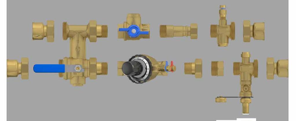
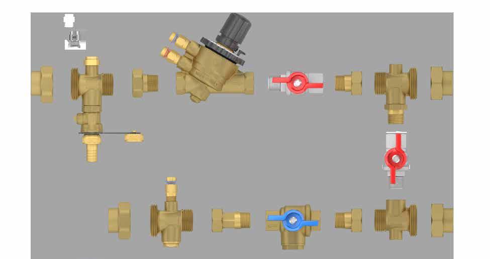
5 DESIGN AND SELECTION HVAC Products Introduction The XT range of Terminal valve assemblies has been designed to include all of the valves and and connections for controlling and maintaining terminal units. These functions are included in a kit, that has been designed to be assembled and mounted in the pipe work to the terminal unit by the installer. Example of fully featured XT801 Function The XT kit includes an EVOPICV axial pressure independent control valve to maintain design flow rates and provide modulating temperature control, also included in the assembly is isolation valves on both flow and return. The flow valve is typically a combined isolation valve and strainer, Filterball. (Y type filter on demand). The return valve is either incorporated on the fixed by-pass or a separate valve on the adjustable centre flushing by-pass. A flushing by-pass and blow down valve are offered so that the valve set and connected terminal unit may be flushed out of circuit and subsequently forward flushed. The XT series has been designed to provide maximum flexibility and allow customization in a number of configurations. Varying the components and adjusting the centre to centre distance of the flushing by-pass. In addition, some specific configurations can be further adjusted by the rotation of individual components to best suit the installation. Schematic Representation XT801 Schematic Representation XT1300 The valve assembly is offered with fixed and adjustable centres, to suit most of the Consultants terminal design. A wide range of end connections are available. Fixed centre to centre by-pass assemblies are the XT600 and XT800 range Adjustable centre to centre by-pass assemblies are the XT1300 range to XT3000 range 1


 and")

6 Configurations Fixed centre to centre distance. This configuration includes the following products which can be partially modified according to customer needs. They are supplied with 40 mm or 80 mm centre to centre distance by-pass (main riser side) and with or without tees with drain, air vent and additional pressure gauge. XT600 and XT601series XT800 and XT801 series XT850 and XT851 series 2
7 Selection The selection of a fixed by-pass assembly is made on piping centres, pressure loss and flow rates. A number of fixed centre assemblies and their configurations have already been detailed. Several more variations including different sizes of EVOPICV, the inclusion of draining and venting and the type/size of end connections have been included in the design selection table below. To ensure that there is sufficient differential pressure through the index terminal unit and the Pressure Independent Control valve the minimum assembly differential pressure has been determined and also included in the design selection table below. Base Code Centre to centre Connections available Flow rates range PICV Min ΔP Assy Min ΔP Kv by-pass Filtering Capacity Drain and air vent Additional pressure gauge [mm] Min [l/h] Max [l/h] [kpa] [kpa] μm XT In 60 Out ½ F x ½ F No No XT In 60 Out ½ F union end x ½ F ¾ F union end x ½ F ½ M union end x ½ F ¾ M union end x ½ F Yes Yes XT ½ F union end x ½ F ¾ F union end x ½ F ½ M union end x ½ F ¾ M union end x ½ F ¾ F x ¾ F union end ¾ F x ¾ M union end ¾ F x 1 F union end ¾ F x 1 M union end 1 F double union end 1 M double union end No No XT ½ F double union end ½ M double union end ¾ F double union end ¾ M double union end 1 F double union end 1 M double union end Yes Yes XT F double union end 1 M double union end No No XT F double union end 1 M double union end Yes Yes The flow rate range indicates the maximum and minimum range of design flow rates that the XT can be used to control and measure. The fixed centre XT by-pass selection can be made on min and max flow range depending on the PICV used. A flow measuring Venturi can be included in the assembly to verify flow. However only differential pressure can be measured across the PICV and if appropriate test points fitted across the terminal device. Sizing PICV valves at their maximum duty should be avoided. A safety margin for possible flow rate changes and water balancing should always be a consideration. PICV Min ΔP is the minimum differential pressure required to provide pressure independent flow control for each PICV selection, where the PICV is 100% open. This value reduces as the valve is regulated. Assembly Min ΔP is the pressure loss through the XT with the PICV valve set to provide the maximum extended range flow rate and allowing for the minimum differential pressure requirement of the PICV to be met. This value can be used during pump selection. The inclusion of accessories such as Tees to allow for the inclusion of drains, air vents, unions Tees with caps to allow for the inclusion of pressure gauge Filterball with drain (an alternative to Tee with drain) Venturi flow measurement (appropriately sized to achieved design signal) Insulation case for heating and chilled water Flexible hose pipes for terminal connections 3


8 Standard configuration Optional configuration 4


9 Variable centre to centre distance. An adjustable centre to centre by-pass has been designed by Pettinaroli to meet the needs of customers who prefer to customize their assemblies to suit Consultant requirements and on site conditions. It is supplied with a variable centre to centre distance bypass, from 130 mm to 300 mm, which has to be specify by the customer. A Pettinaroli typical assembly and configurations includes different sizes of EVOPICV, the inclusion of a Filterball valve in the flow, an isolation valve in the return and flushing by-pass. The inclusion of drains, air vents, Y type strainers and Venturi flow measurement are available options. The valves included in the customized XT assemble can also be orientated as required. Terminal unit connections mounted either in a parallel to the flow or at 45 degrees orientation are best served by the horizontal configuration. Terminal unit connections mounted vertically will typical required left hand and right hand variable centre distance XT units. Two Pettinaroli XT assemblies are shown below. Pictures of the XT variable centre to centre distance Selection Selection is performed on centre to centre distance of the by-pass and on design flow rate. There are several variations of the EVOPICV and additional components; the selection table shows the valve and the connection selections based on flow rate and by-pass distance. To ensure that there is sufficient differential pressure through the index terminal unit and the Pressure Independent Control valve the minimum assembly differential pressure has been determined and also included in the design selection table below. Base Code Centre to centre Connections available Flow rates range PICV Min ΔP Assy Min ΔP Kv by-pass Filtering Capacity [mm] Min [l/h] Max [l/h] [kpa] [kpa] μm ½ F x ½ F union end ½ F x ¾ F union end XT ---- from 130 to 300 ¾ F x ¾ F union end ,5 700 ¾ F double union end 1 F union end x ¾ F union end ¾ F union end x 1 F union end 1 F double union end The flow rate range indicates the maximum and minimum range of design flow rates that the XT can be used to control and measure. The fixed centre XT by-pass selection can be made on min and max flow range depending on the PICV used. A flow measuring Venturi can be included in the assembly to verify flow. However only differential pressure can be measured across the PICV and if appropriate test points fitted across the terminal device. Sizing PICV valves at their maximum duty should be avoided. A safety margin for possible flow rate changes and water balancing should always be a consideration. The inclusion of accessories such as Tees to allow for the inclusion of drains, air vents, unions Tees with caps to allow for the inclusion of pressure gauge Filterball with drain (an alternative to Tee with drain) Venturi flow measurement (appropriately sized to achieved design signal) Insulation case for heating and chilled water Flexible hose pipes for terminal connections 5


10 Standard configuration Optional configuration 6


11 Flow rate control The internal pressure regulator (shown in red below) maintains a constant differential pressure across the seats (P2 P3 in the diagram below) in the EVOPICV. As flow rate is proportional to the product of differential pressure and area of passage, holding the differential pressure constant means that flow rate is only determined by the area of passage. The design flow rate is set using the black hand wheel on the EVOPICV valve. Moving this hand wheel reduces the area of passage through the pre- setting seat of the EVOPICV valve. Temperature control P2 Pre-setting seat P1 P3 B A Pressure regulator Cross Sectional view of the EVOPICV The hand wheel is graduated in percentage of the maximum flow through the valve. Upon receipt of the required design flow rates Fratelli Pettinaroli will return a schedule of valve selections along with the pre-set positions. Indication of how the Pre-Setting Seat Operates Temperature control The EVOPICV also includes an oblique type globe valve for temperature control purposes. This globe valve is capable of being controlled by a wide range of actuators, including thermoelectric actuators and motorised actuators. Authority The authority (n) of a valve can be calculated from the pressure drop across that valve compared with the local system. In this case written as n = PV / Psys In the case of a pressure independent control valve the differential pressure across the control valve is controlled to the same value regardless of whether the valve is fully open, closed or at part load. This means that a pressure independent control valve has an authority of 1. For more information on designing PICV systems please see Fratelli Pettinaroli Definitive guide to Pressure Independent Control Valves. 7
12 Labelling and identification The labelling is also intended to make the flow and selection criteria clear when to technician is working on it. Therefore, the size of PICV fitted can be identified by the markings on the setting hand wheel and chrome disk on the head work. Valve type Part Code on Hand Wheel Chrome Disc Marking 91VL 91VL ½ 150 l/h 150 l/h 91L 91L ½ 600 l/h 600 l/h 91H 91H ½ 780 l/h 780 l/h 91L 91L ¾ 1000 l/h 1000 l/h 91H 91H ¾ 1500 l/h 1500 l/h 93L 93L l/h 2200 l/h 93H 93H l/h 2700 l/h 93H 93H 1 1/4" 3000 l/h 3000 l/h Table 1 Testing Each valve set is leak tested by means of air pressure decay using a fill pressure of 4 bar against with a maximum acceptable leakage of 90 cm 3 /h. DATA Characteristic Pressure rating Flow rate range Working temperature range Working differential pressure range Flow control accuracy (linearity and hysteresis) Control valve characteristic Control valve leakage rate to IEC PN25 (PN16 with flexible hoses) l/h dependent on valve selection C kPa minimum depends on valve and setting ±10% across working DP range at 100% flow Equal percentage depends on actuator Class IV Available thread types BSP and NPT (*) * The XT kits with NPT thread have different code following the example: XT601 (BSP) becomes X601/A (NPT) 8
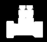
13 DRAWINGS HVAC Products "Rp 1 2"G "Rp 1 2"G XT "Rc 1 2"G "Rc 1 2"G XT "Rp 3 4"Rp "Rc 3 4"Rc XT800 3/4" 9
14 XT800 1" "Rc 1"Rc 1"Rc 1"Rc 1"G 1"Rc 1"G 1"Rc "Rc 3 4"Rc 3 4"Rc 3 4"Rc 9 3 4"Rc 3 4"Rc 9 3 4"Rc 3 4"Rc XT801 3/4" 1"Rc "Rc 188 1"Rc 1"Rc XT801 1" 10
15 "Rc 8.1 1"Rc 1"Rc 1"Rc "G 1"Rc 1"G 1"Rc XT XT851 11
16 "Rc 1 2"Rc "Rc 1 2 "Rc XT variable center to center distance with accessories "Rp 1 2"Rp 1 2 "Rc 1 2 "Rc XT variable center to center distance 12
17 "NPT 1 2"NPT "NPT 1 2 "NPT "NPT 1 2"NPT 3 4"NPT 3 4"NPT 3 4"NPT 3 4"NPT 1 2"NPT 1 2"NPT X601/A 40 to 60 mm center to center distance NPT thread "NPT 3 4"NPT "NPT 3 4"NPT X801/A 80 mm center to center distance NPT thread 13
18 PERFORMANCE CHARTS HVAC Products Dynamic Flow Data The dynamic flow charts presented below indicate the flow response in l/h for several particular valve settings with varying differential pressure. This allows the performance of the valve to be evaluated and the start-up pressure (the differential at which the valve starts to control the flow rate) to be observed. The charts below show the pressure loss across the entire XT assembly; measurements were taken at the inlet and outlet connection. 200 Valve set XT series with 150 l/h EVOPICV 150 Flow [l/h] VL 1/2" [Max 150 l/h] 150 [l/h] 50 Minimum ΔP at max flow Pressure drop across the entire valve assembly [kpa] 700 Valve set XT series with 600 l/h EVOPICV Flow [l/h] L 1/2" [Max 600 l/h] 600 [l/h] 200 Minimum ΔP at max flow Pressure drop across the entire valve assembly [kpa] 14
19 900 Valve set XT series with 780 l/h EVOPICV Flow [l/h] H 1/2" [Max 780 l/h] 780 [l/h] 300 Minimum ΔP at max flow Pressure drop across the entire valve assembly [kpa] 1100 Valve set XT series with 1000 l/h EVOPICV Flow [l/h] /4" [Max 1000 l/h] 1000 [l/h] Minimum ΔP at max flow Pressure drop across the entire valve assembly [kpa] 15
20 1600 Valve set XT series with 1500 l/h EVOPICV Flow [l/h] Pressure drop across the entire valve assembly [kpa] 91H 3/4" [Max 1500 l/h] 1500 [l/h] Minimum ΔP at max flow Flow [l/h] Valve set XT series with 2200 l/h EVOPICV Pressure drop across the entire valve assembly [kpa] 93L 1" [Max 2200 l/h] 2200 [l/h] Minimum ΔP at max flow 16
21 Flow [l/h] Valve set XT series with 2700 l/h EVOPICV Pressure drop across the entire valve assembly [kpa] 93H 1" [Max 2700 l/h] 2700 [l/h] Minimum ΔP at max flow Flow [l/h] Valve set XT series with 3000 l/h EVOPICV Pressure drop across the entire valve assembly [kpa] 93H 1 1/4" [Max 3000 l/h] 3000 [l/h] Minimum ΔP at max flow 17
22 Control valve characteristic The plot below shows the normalised control valve characteristic when the XT is fitted with the two most common actuator combinations. The VA7482 is a 0-10V proportional actuator and the VA7481 is a 3 point floating type. Control valve characterisation 18

23 INSTALLATION AND OPERATING INSTRUCTIONS HVAC Products Installation Care should be taken when screwing pipe adaptors to the valve set not to over stress the joints, avoiding, where possible, mixing tapered and parallel threads on the same joint. It is also recommend that a liquid pipe sealant or PTFE tape is used in preference to hemp and other fillers. Fratelli Pettinaroli union connectors incorporate hexagon flats for use with non serrated jawed tools; never use Stilsons or other serrated jawed tools to tighten these or any other brass fittings. All union nuts in the standard XT are 42mm across flats; female threaded connections have different size: in this case, connection must be carried out blocking the male thread with a counter key. We would recommend the use of a modified flare nut spanner (as detailed below) or a crows foot spanner. Please observe the stated torque requirements when tightening union joints. 30mm Flare Nut Spanner, Modified with 30mm Slot Always remove any O-rings from solder fittings before applying heat, do not solder union connections in place. When connecting end fittings to the XT ensure that any torque applied is properly countered so that other connections are not loosened and sealants applied by Fratelli Pettinaroli are not damaged. This can generate leakages. When opening and closing the drain valve use a cabinet key (square drive) of the correct size, using a spanner of excessive length or grips can damage the internal stops of the valve. If the kit is not thermally isolated and a drip tray is present, the XT should be properly bracketed to the terminal unit drip dray; the design and construction of the mounting system and ensuring that the drip tray is of sufficient size will be the responsibility of the terminal unit manufacturer. There is a tapped blind hole on the bottom of the flushing by-pass valve intended to facilitate easy and secure bracketing of the valve assembly. This hole size varies in function of the by-pass size: M6 on 40 mm by-pass (XT600, XT601), M10 on 80 mm by-pass (XT800, XT801, XT850, XT851), ¼ NPT on variable centre to centre distance by-pass. Care should be taken to avoid galvanic corrosion where there is metal on metal contact. Media quality It is expect that the system to which the XT is fitted be pre-cleaned and flushed in accordance to the standards and principles detailed in the BSRIA guide Pre commission cleaning of pipework systems (BG29/2012) and the water quality maintained to standards as detailed in BSRIA guide Water treatment for closed water systems (BG50/2013) and UNI8065 standard. The valves used in the XT contain a number of O-Rings, washers and seats made variously of NBR, EPDM, PTFE and FKM, please ensure compatibility of these materials with any water treatments, chemical cleaning agents and other compounds exposed to the media such as pipe sealants. The XT is intended for use with group 2 non dangerous liquids only (dangerous liquids, group 1, are defined in article 2, paragraph 2 of the Directive 67/548/CEE). Note that it is advisable to get a confirmation from the liquids producers regarding their compatibility with the materials the XT is composed of. Flushing and isolation The valve set is configured such that it can be easily flushed out of circuit (by-passed) and also to allow the back flushing of the connected coil, if a tee with drain is installed: reasons are listed below the valve set can only be forward flushed to fill and purge the valve with treated water. a. So as not to flush dirt through the EVOPICV valve b. The EVOPICV valve is a flow limiting valve, by forward flushing through this valve the media velocity may not achieve those needed for an adequate flush In general the flushing procedure can be performed by those valve settings having the drain and should be as follows: 1. Mains flush 2. Flush to drain 3. Forward flush to fill and purge 19
24 Fixed centre to centre distance. Mains flush To perform a mains flush 1. Isolate the flow leg using the isolation valve Filterball 2. Open the flushing by-pass valve, so that the handle is perpendicular to the axis of the by-pass inlets, this also isolates the return leg. Flush to drain The valve set and attached coil can be back-flushed to drain in order to purge and flush the attached coil. This operation can be performed if a tee with drain is set. It can be done in direct or reverse mode. The procedure for XT601, XT801 and XT851 should be as follows: Forward flush to drain 1. Close the EVOPICV either using the knob provided or by driving the actuator closed. 2. Close the flushing by-pass valve, so that the handle is parallel to the axis of the by- pass inlets. 3. Open the flow isolation valve. 4. After attaching a hose to blow down valve using the supplied hose barb, open the blow down valve. Be sure to isolate and cap off the blow down valve before returning the valve set to service. Forward flush to drain from the return Be sure that the flow direction is inverted in the inlet and outlet pipes to the valve set. 1. Close the EVOPICV either using the knob provided or by driving the actuator closed 2. Open the flushing by-pass valve, so that the handle is perpendicular to the axis of the by- pass inlets. It should still be in this position from the mains flush 3. Open the flow isolation valve 4. After attaching a hose to blow down valve using the supplied hose barb, open the blow down valve Be sure to isolate and cap off the blow down valve before returning the valve set to service. 20

25 Filling and purging Once the valve set has been back flushed it is prudent to fill the EVOPICV valve with treated water. To do this 1. Close the flushing by-pass valve, so that the handle is parallel to the axis of the by-pass inlets 2. Open the EVOPICV valve 3. Open the blow down valve to allow a small amount of treated water to be drawn into a bucket thus ensuring the entire valve set is full of the treated water 4. Close the blow down valve and ensure that the cap is replaced Normal operation The valve set should be configured as follows during normal operation. 1. Return isolation valve is open 2. The flushing by-pass valve is closed, so that the handle is parallel with the axis of the valve inlets 3. Any override clutches on the EVOPICV actuator are disengaged, the valve will be positioned as determined by the BMS controller. 21

26 Variable centre to centre distance. Mains flush To perform a mains flush 1. Isolate the flow leg using the isolation valve Filterball 2. Open the flushing by-pass valve. 3. Isolate the return leg using the isolation ball valve. Flush to drain The valve set and attached coil can be back-flushed to drain in order to purge and flush the attached coil. This operation can be performed if a tee with drain is set. It can be done in direct or reverse mode. The procedure for XT601, XT801 and XT851 should be as follows: Forward flush to drain 1. Close the EVOPICV either using the knob provided or by driving the actuator closed. 2. Close the flushing by-pass valve. 3. Open the flow isolation valve. Close the return isolation valve. It should still be in the position from the main flush. 4. After attaching a hose to blow down valve using the supplied hose barb, open the blow down valve. Be sure to isolate and cap off the blow down valve before returning the valve set to service. Forward flush to drain from the return Be sure that the flow direction is inverted in the inlet and outlet pipes to the valve set. 1. Close the EVOPICV either using the knob provided or by driving the actuator closed 2. Open the flushing by-pass valve and close the return isolation ball valve. It should still be in this position from the mains flush 3. Open the flow isolation valve 4. After attaching a hose to blow down valve using the supplied hose barb, open the blow down valve Be sure to isolate and cap off the blow down valve before returning the valve set to service. 22
27 Filling and purging Once the valve set has been back flushed it is prudent to fill the EVOPICV valve with treated water. To do this 1. Close the flushing by-pass valve. 2. Open the EVOPICV valve 3. Open the blow down valve to allow a small amount of treated water to be drawn into a bucket thus ensuring the entire valve set is full of the treated water 4. Close the blow down valve and ensure that the cap is replaced Normal operation The valve set should be configured as follows during normal operation. 1. Flow and return isolation valve is open. 2. The flushing by-pass valve is closed. 3. Any override clutches on the EVOPICV actuator are disengaged, the valve will be positioned as determined by the BMS controller. 23


28 Setting and commissioning For more information on commissioning PICV systems please see Fratelli Pettinaroli Definitive Guide to Pressure Independent Control Valves. The Flow rate can be set by adjusting the black hand-wheel on the EVOPICV to the required position. The set position is expressed as a percentage of the EVOPICV valve s maximum flow rate and is calculated by dividing the design flow by the maximum nominal flow of the valve and multiplying by 100. Setting = Design flow rate Valve maximum flow rate For example where the design flow rate is 450 l/h and the valves maximum flow rate is 600 l/h there are to two main approaches to commissioning the valve assembly. Setting = = 75% Pre-setting With the valve set in the normal operating mode the EVOPICV can then be pre-set to the calculated position as detailed on the selection schedule. Lift the lock pin to unlock the hand-wheel. The hand-wheel is graduated from 100% to 10%, turn the hand-wheel to the calculated percentage as indicated by the lock pin. Press the lock pin to lock the hand-wheel in position. When the valve is pre-set there will be a wider variation in measured results compared to if the valve was set to a flow rate using the venturi flow measurement device according to start-up diagrams on technical manual of EVOPICV. Setting to a flow rate With the manometer connected to the flow measurement station the pre-setting wheel can be adjusted until the correct differential pressure measurement is achieved according to start-up diagrams on technical manual of EVOPICV. The set position should be recorded on the commissioning documentation along with the manometer readings and flow rate. Deviations of more than 15% from the calculated set position should be cause for investigation as they may indicate problems with the local installation or the PICV. Ԑ [± %] ± 20 ± 10 0% 10% 20% 30% 40% 50% 60% 70% 80% 90% 100% Adjusted flow Setting Accuracy vs Hand Wheel Position 24
29 Flow and differential pressure measurements The XT valve assembly can be come equipped with multiple pressure temperature readout ports. These are all of the binder type. With regard to those valve sets which have a tee with additional pressure gauge, all the pressure ports allow for the following measurements to be taken: a. Differential pressure or temperature across terminal unit b. Differential pressure across EVOPICV valve c. Static pressure or temperature at the terminal unit If a venturi flow measurement device is added, flow rate through the terminal unit may be measured. Differential pressure across the terminal unit Connect the low pressure side of the measuring instrument to the high pressure tapping on the EVOPICV and the high pressure side to the tee pressure gauge or to low pressure tapping on the venturi measuring device, when it is installed. Differential pressure across the EVOPICV valve If the EVOPICV has both of it test points fitted then simply connect the measuring instrument to these test points. The high and the low side are indicated by the letters H and L in the body forging. Please note that flow rate cannot be measured across the EVOPICV valve, if a flow rate is required always use the venturi. To measure the flow rate passing through the terminal unit Connect the measurement instrument (U-tube manometer or electronic manometer) to the venturi flow measurement device, being sure to purge the pressure lines. Use the stated Kvs to calculate the flow rate based on the differential pressure reading taken and the following formula: Q=( P Kvs)/36 if Q = volume flow rate in l/s or Q=100 P Kvs if Q = volume flow rate in l/h Kvs = Valve factor as stated on the valve tag or schedule ΔP = Differential pressure measurement in kpa Maintenance The valve set is maintenance free as far as regular service requirements, however the valve assembly can facilitate some maintenance activities. If there are any specific requirements e.g. for the end fittings these will be detailed on supplementary sheets. It should be noted that when in the closed position (by pass handle perpendicular with the axis of the by-pass inlets and isolation valve closed), the flushing by-pass valve still allows water to by-pass through the connecting loop. Leaving the valve in this position is not recommended when a system has been balanced and is in service as it will provide an uncontrolled water way and potentially affect the balance of the system. If a particular coil is to be taken out of service for an extended period of time then the valve set should be isolated using the flow isolation valve only. The EVOPICV can then be driven to a fully closed position by the actuator or manual protection cap. Alternatively it is possible to fully isolate the terminal legs of the by-pass by closing the isolation valve and removing the handle of the by-pass when the valves are in the closed position. The ball may then be manually rotated 180. The XT valve set with variable centre to centre distance by-pass allows easier operation: to fully isolate the terminal legs, just close two isolation valves on the return and flow legs; the by-pass isolation valve has to be closed too. Although the flushing by-pass valve will also isolate the flow leg it will simultaneously open the by-pass which may mean that the by-pass circuit itself becomes the most favoured loop on a circuit. This could result in the entire floor being put out of balance. Replacement of the terminal unit The valve set is installed with unions or hose pipes at the coil end. These unions allow the coil unit to be removed whilst leaving the valve set in situ to isolate the pipework. To dismantle these unions please ensure 1. That the flow leg isolation valve is closed and that the by-pass valve is opened isolating the return leg 2. The EVOPICV valve is closed, either by the BMS controller or by means of the override clutch on the actuator 3. The unions (when provided) require a 42mm spanner whereas use the suitable spanner to loosen flexible hoses unions 4. Replace the coil as per the manufacturer s instructions 5. If the coil connection blocks and O-rings are serviceable after they have been dismantled then they may be replaced onto the new coil unit, otherwise contact Fratelli Pettinaroli for replacements 25


30 Replacement of the diaphragm of EVOPICV 91 valve - 091SET maintenance kit For further information please refer to instruction SET 091SET maintenance kit Step 1a: remove completely the knob 26 mm adaptor Key Nose Plier Step 1b: remove the actuator and the adapter. Step 2: using the 26mm adaptor key provided to remove the headwork. Align latches. Step 3: using a 26mm spanner unscrew the headwork. Step 4: remove the headwork. 26


31 Step 5: Insert the nose pliers through the center of the cartridge Step 6: press the plier and pull the cartridge up out of the body Step 7: Insert the new cartridge Step 8: Replace the headwork Step 9: Screw the headwork with 15/20 Nm torque reaching the initial position of the lock pin Step 10: remove the 26 mm adapter key and replace the actuator a adapter Initial position 27

.")
 Should the EVOPICV need to be replaced for any reason this can be accomplished by 1. Closing the flow leg isolation valve 2.")
32 Replacement of the diaphragm of EVOPICV 93 valve Step 1: unscrew bottom cap Step 2: unscrew the Diaphragm using an hexagonal socket wrench Step 3: manually pull out the diaphragm. Push the new one in and follow the instruction in reverse. Wear gloves. Replacement parts Every maintenance action must be done by qualified tecnician, prior comunication to Fratelli Pettinaroli. For any request and doubt, please contact the manufactor. Main parts in the XT can be field replaced; a ½ control valve may be exchanged for a ¾ or 1" one and vice versa. Care must be taken if the control valve is exchanged for another variant that the matching venturi is also installed (when provided). Every time a technician modifies configuration or replaces a component or a spare part, Fratelli Pettinaroli cannot ensure the watertight seal of the kit. Replacement of EVOPICV valve (just when a drain is provided) Should the EVOPICV need to be replaced for any reason this can be accomplished by 1. Closing the flow leg isolation valve 2. Open the flushing by-pass valve, so that the handle is perpendicular to the axis of the by- pass inlets. This will also isolate return leg 3. After attaching a hose union and hose to the blow down valve (when provided), open the blow down valve and carefully release the pressure within the coil. Drain as much of the contents off as possible into a bucket before commencing other works 4. The EVOPICV can be removed by loosening the union joints at the tee end and by-pass end of the EVOPICV valve 5. Remove old EVOPICV 6. Install new EVOPICV by following the instruction in reverse. Fill the system following the procedure "Filling and purging". Be sure the system does not show any leakage For convenience, EVOPICV and union tails will be replaced as a unit. 28


33 INDIVIDUAL COMPONENTS HVAC Products EVOPICV For more information on commissioning PICV systems please see Fratelli Pettinaroli Definitive Guide to Pressure Independent Control Valves. One of problems associated with 2 port control is sizing and making sure all of the control valves have adequate authority. Whilst this problem is helped by the use of differential pressure controllers it can still be difficult to maintain good authorities without specifying that each terminal unit requires a DPCV. Using traditional valves this would be a very expensive design approach. The pressure independent control valve (PICV) combines the functions of a differential pressure controller, regulation valve and 2 port control valve into a single body. The EVOPICV incorporates a small diaphragm type DPCV in order to keep a constant differential pressure across an orifice and to provide a constant flow rate whilst the differential pressure is with the operating limits of the valve. Beyond these working pressures the valve acts as a fixed orifice. Component Material Body DZR BRASS CW602N (EN 12167) Headwork BRASS CW614N (EN 12164) Cartridge sleeve Stainless Steel Diaphragm BRASS CW614N - High resistance EPDM O-Rings Adjustment ring EPDM-X PSU EVOPICV 91 valve. Connections ½ F ¾ F 1 F Component Material Body DZR BRASS CW602N (EN 12167) Headwork BRASS CW614N (EN 12164) Cartridge sleeve Diaphragm O-Rings Adjustment ring Connections Stainless Steel BRASS CW614N - High resistance EPDM EPDM-X PSU ¾ Union End 1 Union End - 1 1/4" Union End EVOPICV 93 valve. 29
34 Making this orifice adjustable allows the valve to be pre-set deliver a range of flow rates. In the case of the EVOPICV valve this adjustment can be made in situ without removing any covers or actuators, the adjustment wheel is lockable by means of a combined memory stop and indicator. The EVOPICV valve also includes 2 port temperature control by means of an oblique pattern globe valve. The plug of the globe valve is machined to give a near equi-percentage flow control characteristic. Due to the fact that the differential pressure across the valve seat is constant it can be said that the authority of this control valve is very close to 1. The EVOPICV can be fitted with a range of actuators including thermo-electric ON/OFF, modulating actuators and motorised actuators. When shut tight, the globe valve is a metal on metal seal and as such the leakage rate should be no more than 0.01% of the nominal maximum flow of the valve as defined by class IV of IEC Due to the way the EVOPICV valve controls the flow rate, irrespective of differential pressure branch and sub mains, balancing valves are not required. The flow rate is maintained at the terminal unit regardless of system conditions making the valve ideal for systems with inverter driven pumps. Characteristic Pressure rating Flow rate range Working differential pressure range Accuracy (linearity and hysteresis) Leakage rate to IEC PN l/s dependent on valve selection kPa minimum depends on valve and setting, valve will operate up to 600kPa, 400kPa is recommended to avoid unwanted noise ±10% across working DP range at 100% flow Class IV 30

 strainer basket, grades as coarse as 800 micron and as fine as 150 microns are available as optional extras.")
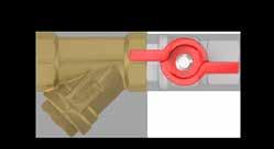
35 Filterball strainer The strainer basket is mounted in the ball of the isolation valve itself; a side mounted inspection port allows the strainer basket to be removed for cleaning and maintenance without the need for additional isolation valves. Both steel and aluminium butterfly handles are available. 51F The Filterball is machined from a hot forged DZR brass body, the seats are virgin PTFE and the stem is sealed by a pair of Viton O-Rings in addition to a PTFE gland. As standard the Filterball comes fitted with a 700 micron (28 mesh) strainer basket, grades as coarse as 800 micron and as fine as 150 microns are available as optional extras. Component Material Body DZR BRASS CW602N (EN 12167) Ball CHROME PLATED DZR BRASS CW602N (EN 12167) Insert DZR BRASS CW602N (EN 12167) Stem DZR BRASS CW602N (EN 12164) Seats O-Rings Strainer basket Circlip PTFE FKM STAINLESS STEEL POSPHOR BRONZE Characteristic Pressure rating Strainer size KV Size Connections PN micron (28 Mesh) 7 (DN15) and 7.5 (DN20) DN15 and DN20 1/2" F - 3/4" F 31


 Coil connection tee with various accessories Characteristic Pressure rating PN25 Connections 3/4\" E x 1 1/8\" Blow")

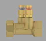
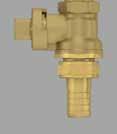
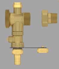
36 Coil connection tee The coil connection set is intended to provide a simple way of connecting the XT unit to the terminal coil tails, when provided. The coil connection tee 1020 and 1020P can be configured with male and female end connections. It has ports for a drain and optional accessory such as an air vent, test plug or cap. The final function of the coil connection tee is to provide a union joint at a position where the coil could be removed whilst the bulk of the XT remains connected to the pipework providing isolation. Component Material Body BRASS CW617N (EN 12165) Coil connection tee with various accessories Characteristic Pressure rating PN25 Connections 3/4" E x 1 1/8" Blow down connection Air vent / Pressure gauge connection 1/2" F 1/4" F NPT Blow down valve The blow down valve is of the ball type, the handle is of the square drive type and may be opened and closed using a 7mm square drive or spanner, shut off is positive. The connection to the XT is sealed by use of an O-ring. A cap and 14.5mm hose barb are included. Component Material Body BRASS CW617N (EN 12165) Ball TEA PLATED BRASS CW617N (EN 12165) Insert BRASS CW614N (EN 12164) Seats Stem O-Rings PTFE FKM Stem BRASS CW614N (EN 12164) O-Ring EPDM Characteristic Pressure Rating Connections PN25 1/2" M 32

 The Fratelli Pettinaroli flushing by-pass valve has")
 BRASS CW617N (EN 12165) Balls TEA")
 BRASS CW614N (EN 12164) The by-pass valve XT3 comprises of two through connections joined by a perpendicular by-pass section.")


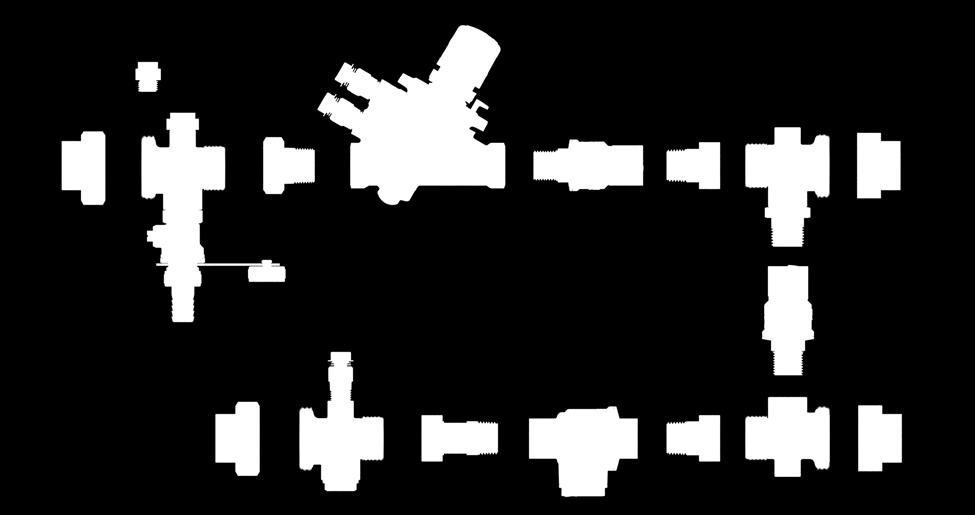
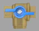
37 Flushing by-pass BSRIA application guide Pre-Commission cleaning of pipework systems recommends that all terminal units are fitted with fixed flushing by-passes. This BSRIA guide is referenced in the CIBSE code W Water Distribution systems. The XT valve set series is equipped with three different types of flushing by-pass: 40 mm centre to centre distance by-pass valve XT3B DN20 80 mm centre to centre distance by-pass valve XT3B DN25 Variable centre to centre distance by-pass set (130 mm to 300 mm) The Fratelli Pettinaroli flushing by-pass valve has been designed for all types of hydronic terminal unit. Main Flush Operating Mode Forward flush from the return Component material XT3B DN20 XT3B DN25 Body BRASS CW617N (EN 12165) BRASS CW617N (EN 12165) Balls TEA PLATED BRASS CW617N (EN 12165) CHROME PLATED BRASS CW617N (EN 12165) Insert BRASS CW617N (EN 12165) BRASS CW617N (EN 12165) Seats PTFE PTFE O-Rings FKM FKM Stems BRASS CW614N (EN 12164) BRASS CW614N (EN 12164) The by-pass valve XT3 comprises of two through connections joined by a perpendicular by-pass section. The top connection does not incorporate any ball valve, the bottom through section contains a three ported ball valve which allows for two operation modes - by- pass and flow. These flow sections are arranged at two distances as mentioned before: 40mm centres which is increased up to 60 mm by means of two eccentrics in order to be directly installed on 60mm centre inlet/outlets terminal units; 80mm centres so as to provide a way to directly mount any valve set to a fan coil unit with matching 80mm centre inlet/outlets. The bottom ball valve has three ports machined in a T configuration. In flow mode, the middle port is sealed against the third and fourth seats preventing water from flowing through the by-pass. As the valve is moved into by-pass mode the outlet side of bottom return connection is isolated whilst the bypass connection is opened allowing the two inlet connections to be flushed through. Connections to pipe line are female in XT3 and female union end in XT3 DN25. Characteristic XT3B DN20 XT3B DN25 Pressure rating PN25 PN25 Bore size (flow mode) [mm] Bore size (by-pass mode) [mm] Connections ½ F x ¾ E ¾ F union end 33


 and the return leg ball valve is closed, the outlet side of bottom")

 BRASS CW617N (EN 12165) Balls - - TEA PLATED BRASS CW617N (EN 12165) Insert - - BRASS CW617N (EN 12165) Seats -")
38 The variable centres by-pass is a set of components. It comprises of two through tees connections 1020 joined by a perpendicular by-pass section made by a two ports isolation ballvalve 52/1 and a pipe section. The brass pipe which constitutes the variable length element is 3 mm thick. The top leg does not meet any ball valve before the Filterball valve, the bottom through section is followed by an isolation 2 ports ball valve. The combined action of those three ball valves allows for two operation modes - flushing and flow. These flow sections are arranged at variable centre distances, as mentioned before: from 130 mm, any distance can be get until 300 mm. In flow mode, the by-pass pipe is sealed by the specific ballvalve which prevents water from flowing through the by-pass. As the by-pass valve is moved into by-pass mode (it is opened) and the return leg ball valve is closed, the outlet side of bottom return connection is isolated whilst the by-pass connection is opened allowing the two inlet connections to be flushed through. Connections to pipe line are female ¾ or 1 female union end. Main Flush Operating Mode Forward flush from the return Component material Pipe /1 Body BRASS CW614N (EN 12164) BRASS CW617N (EN 12165) BRASS CW617N (EN 12165) Balls - - TEA PLATED BRASS CW617N (EN 12165) Insert - - BRASS CW617N (EN 12165) Seats - - PTFE O-Rings - - FKM Stems - - BRASS CW614N (EN 12164) Characteristic Pressure rating By-pass PN25 Bore size (flow mode) [mm] 15 Bore size (by-pass mode) [mm] 15 Connections ½ M x ¾ F union end 34

 PN25 ½ M x ½ F and 3/4\" M x 3/4\" F 1.")
39 Venturi flow measurement (optional) The Terminator Interchangeable venturi housing is based on the proven venturi inserts used in our Terminator commissioning valve. The same venturi inserts are used but we have recalculated the Kvs values in situ in its specific housing, this means that each venturi is calibrated for the exact situation in which it is used. Component Material Body DZR BRASS CW602N (EN 12165) Venturi insert BRASS CW614N (EN 12164) Test point BRASS CW617N (EN 12165) Test point core O-Rings Ethylene propylene rubber EPDM EPDM Interchangeable venturi flow measurement device Characteristic Pressure rating Connection Working differential pressure range Accuracy (linearity) PN25 ½ M x ½ F and 3/4" M x 3/4" F kPa ±5% across working DP range Sizing of the venturi is usually carried out to give differential pressure readings between 2 and 10kPa as this is the most accurate range of the venturi but also allows digital manometers to be used. The venturi allows high signals of up to 15kPa to be achieved without significant residual pressure loss. The Terminator interchangeable venturi housing is machined from a hot forged DZR brass body. The venturi insert fitted will be identified by a coloured band on the high pressure test point. This all gives a quick guide to main Venturi insert and control valve selection. Other Venturi inserts are available for very high flow rates. Venturi size Colour 3 mm WHITE 4.25 mm GREEN 6 mm ORANGE 7.5 mm BLUE 9 mm YELLOW 10.5 mm RED 35
40 Flow measurement chart The chart below plots the Kvs of the various venturi inserts when installed in the complete valve assembly. The selection boundaries are also shown on the chart, the green bars show the typical range of flow rates that each venturi can be selected to measure (between 2 and 10 kpa). The red bars show the maximum useful range of the venturi, readings beneath 0.5kPa will not be as accurate, and above 15kPa the intrinsic pressure loss of the venturi will be too high. XT Measuring Station Kvs Replacement of venturi The venturi can be replaced in the field; for convenience the entire venturi housing and insert along with the inlet union tail will be replaced as a unit. To replace the venturi 1. Isolate flow and return isolation valves 2. The EVOPICV valve is closed, either by the BMS controller or by means of the manual knob. 3. Use blow down valve to de-pressurise and drain the terminal 4. The union nuts require a 30mm spanner, a modified flare nut or crows foot spanner is recommended 5. Loosen the front and back union nut on the flow leg 6. Remove old venturi housing 7. Install new venturi housing by following the instructions in reverse. Be sure the system does not show any leakage 36
 Nut BRASS CW617N (EN 12165) O-Rings Connection EPDM 1 1/8\" union end x 1/2\" F - 3/4\" F - 1\" F Insulating case (optional) The XT valve assembly series")

41 Union connections Union connections are machined from hot forged brass billets. Both female and male union connections are available. Female ones can be selected between BSP and NPT type. Component Material Body BRASS CW617N (EN 12165) Nut BRASS CW617N (EN 12165) O-Rings Connection EPDM 1 1/8" union end x 1/2" F - 3/4" F - 1" F Insulating case (optional) The XT valve assembly series has a complete range of insulating cases for heating and cooling. Insulation guarantees high energy savings by reducing heat losses throughout pipe lines: in this way energy carrier reaches terminals with most suitable temperature. Moreover, insulation must be placed on cooling systems to avoid also condensation on pipes and valves which may damage structural elements, false ceilings and decorative items. Cases can be ordered separately or they can be delivered along with kits. They are properly customized on valve set size and shape. Both type of cases for heating and cooling are 20mm thick and they are made by polyethylene cross linked foam. What it changes between cooling and heating cases is the insulation of the actuator: indeed, cooling cases are delivered with an additional case which has to be fit onto the actuator whereas heating variants are devoid of that. In this way, heat exchange is promoted by the actuator side during the heating season whereas the actuator little case prevents actuator failures due to condensate drip. Cases are supplied as two shells, upper and lower parts, which are held together by tape; Fratelli Pettinaroli can provide two type of tape to be chosen between Velcro and the cheaper double-side adhesive tape. If needed, other mounting configurations are available on demand. Insulating shells should be installed after commissioning. Union connections, the actuator connection and all the coupling line between shells should be insulated by using thermal tape. Insulating case Material Density [kg/m3] Thermal conductivity [W/m K] Features Polyethylene cross linked foam 30 x 15mm + 80 x 5mm 0.04 (density 30 kg/m3) Fire resistance (UNI8457, UNI 9174) Class 1 Operating temperature C 37

42 Flexible hoses (optional) Despite Pettinaroli valve assembly XT series covers an extremely wide range of centre distances, inlet pipes and coil connections may have various distances so as flexible hoses are needed to connect the assembly to any pipe. Fratelli Pettinaroli s flexible hoses are all EPDM flexible pipes protected by stainless steel twist. Connection ends are made by machined brass. Fratelli Pettinaroli can provide a complete range of connections end and nominal diameters in order to cover every customer request. Available connection ends are listed as follows: Male thread Female flat union end Female flat union end with nipple Hoses can be selected among three nominal diameters: DN13, DN15, DN19 and DN25. Moreover, the customer can choose among several thickness of insulating expanded elastomeric pipes. Insulation pipes are available in several thickness: 6mm, 9mm, 13mm, 19mm, 25mm, 32mm. Component Internal pipe Twist Material EPDM Stainless steel Connections BRASS CW614N (EN 12164) O-Rings EPDM Characteristic Male thread Female flat union with nipple Female flat union end Pressure Rating PN16 PN16 PN16 Temperature Range 5 90 C 5 90 C 5 90 C Connection ½ ¾ 1 ½ ¾ ½ ¾ Nominal Diameter DN13 DN15 DN19 - DN25 DN13 DN15 DN19 - DN25 DN13 DN15 DN19 - DN25 Length cm cm cm Tighten torque 35 Nm 35 Nm Spanner 24mm (½ ) 30mm (¾ ) 24mm (½ ) 30mm (¾ ) 38

43 ACTUATION HVAC Products Actuator selection The table below shows actuator part numbers for different control types. Type Standard Stroke Adaptor 24 V, 0-10 V Proportional VA V, 3 Point Floating VA V, 3 Point floating VA7481 3,2 mm 0A7010 6,3 mm 0A748X 3,2 mm 0A7010 6,3 mm 0A748X 3,2 mm 0A7010 6,3 mm 0A748X 24 V, 0-10 V Proportional Thermic A544P3 4 mm VA64 24 V, ON-OFF Thermic A544O2 or A544O4 4 mm VA V, ON-OFF Thermic A542O2 or A542O4 4 mm VA64 Actuator fitting Motorised actuators To mount the actuator, first fully remove the black isolation cap. The actuator is supplied with a separate actuator mounting ring, this is mounted onto the valve headwork, if desired use a spot of thread locking adhesive to ensure the ring is retained with the valve. Making sure that the actuator is in its fully open position, mount the actuator on the headwork and then tighten the collar nut until it is hand tight. Prior to removing the actuator it should be driven fully open before being powered down, this will ensure that it can be properly fitted again; do not try to fit an actuator with the spindle in an extended position. Fitting motorised actuator to PICV 39


44 Thermic actuators EVOPICV To mount the actuator, first fully remove the black isolation cap. The actuator is supplied with a separate actuator mounting ring, this is mounted onto the valve headwork, if desired use a spot of thread locking adhesive to ensure the ring is retained with the valve. To mount the actuator it is then pushed onto the adapter ring until the clips retain the actuator. Thermic actuators are supplied in a first open position, this means that they can be fitted easily. Once the actuators have been powered on, the actuator will be more difficult to fit unless driven open. Fitting thermic actuator to PICV Removing black protection handle Do not attempt to fit the actuator if the black handle has not been fully removed. Sometimes the lower portion of the handle is too tight to remove by hand, in this case gently use a pair of grips to remove the handle. Correct, handle fully removed Incorrect, handle partially removed 40

45 Actuator details 0-10V Proportional (configurable) This is our recommended actuator for both the EVOPICV 91 and 93 when fitted to forced convection terminal devices such as fan coils and air handing units. The actuator is a compact unit that is field configurable such that is suitable for a wide range of applications. Control input The actuator can be controlled by a number of different signals, including 0-10V, 2-10V, 0-5V, 5-10V and 4-20mA. The actuator is factory set to 0-10V. Stroke direction The stroke direction is factory set to direct acting, this may be changed in the field if required. In order to suit the EVOPICV, the actuator should be set to reverse acting as the EVOPICV is normally open. This will allow the actuator to work with controllers that are set to direct acting without needing any change to the controls. Stroke length In order to adapt the stroke length to different valves, there is jumper that will change the effective stroke length. This jumper is factory set but can be changed on site if required. Please note that while the actuator will self calibrate to find the closing position, it works on a fixed stroke basis. Calibration Cycle When the power is applied, the actuator self-calibrates performing a complete cycle. The actuator moves the stem down for a complete mechanical valve stroke until no changes are detected. Once the auto-zero is detected the actuator moves the stem accordingly with the input signal. Replaceable Cable The connection cable is fitted with a plug so that the actuator can be swapped without unwiring the cable from the controller. 3 Point motorised actuators 0-10V motorised actuator 24v 3 Point motorised This a 24v 3 point floating actuator for the EVOPICV 91 and 93, suitable fitted to forced convection terminal devices such as fan coils and air handing units. The actuator is a compact unit that is suitable for several sizes of valve. A 230v version is available for special applications. Control input The actuator is controlled on a drive open, drive closed basis. When the signal is applied to the black and red wires, the actuator stem extends. When the signal is removed the actuator remains in position. If the signal remains applied to the red wire, the actuator will time out and shut off the motor after approximately 90 seconds. When the signal is applied to the black and orange wires, the actuator stem retracts. When the signal is removed the actuator remains in position. If the signal remains applied to the orange wire, the actuator will time out and shut off the motor after approximately 90 seconds. Controller Strategy The actuator has a maximum stroke of 6mm making it suitable for a number of different valves in our range (both 91 and 93 EVOPICV), however there are a few things that need to be taken account of in the BMS controller strategy. To ensure the best control characterisation it is vital to match drive time to the valve stroke so that there is no air gap between the actuator spindle and the valve spindle. The drive time should be calculated by multiplying the stroke length of the valve in mm by the time to drive 1mm. All 3 point actuators need periodic re-synchronisation to account for positional drift, the re- synchronisation time should be set to 90 seconds in the closing direction of the valve. 41

46 24V or 230V Thermic On/Off This actuator is suitable for passive terminal devices such as radiators and chilled beams, it is cost effective and operates silently. The 4 mm stroke actuator fits only EVOPICV 91 series while the 6 mm stroke is mounted on EVOPICV 93 series. The actuator mechanism uses a PTC resistor- heated elastic element and a compression spring. The wax element is heated by applying the operating voltage and moves the integrated ram. The force generated by the movement is transferred to the valve stem and thus opens and closes the valve. Fratelli Pettinaroli provides also a variation of 2 wires standard actuator: the 4 wires actuator, with additional microswitch, can be selected in order to have a supplementary control signal for a pump, a boiler, etc. The standard version the Normally Closed (NC) one but also the Normally Open (NO) one is available. The actuator is nominally ON/OFF but can be controlled in a more modulating fashion by pulse pausing the controller output (Pulse Width Modulation). Our standard supply of these actuators is with fixed cable. If required, a premium version with 5 m long detachable cable is available. First-open function In its delivery condition, the actuator is normally open due to the First-Open function. This enables heating operation during the carcass construction phase even when the electric wiring of the single room control is not yet complete. When commissioning the system at a later date, the First-Open function is automatically unlocked by applying the operating voltage (for more than 6 minutes) and the actuator is fully operable. Function indicator The actuator has a function indicator in the form of a blue band on the actuator stem, this allows identifying the operating condition (actuator powered or not, corresponding to valve open or closed for Normally Closed actuator) at a glance. Hysteresis There is an inherent hysteresis in the operation of any thermic type actuator, when the actuator has not been used for a period of time there is an extra warm up period whilst the wax is heated up to its working temperature. When the voltage is removed from the actuator there is also cool down period before the actuator will begin to close due to the thermal mass of the wax. Thermic ON/OFF actuator 0-10V Thermic actuator 0-10V Proportional thermic The 0-10V proportional thermic actuator is offered as an alternative to the motorised proportional actuator. Our standard supply of these actuators is premium version with detachable cable and it is available with 4 or 6mm stroke. Calibration For the variant "normally closed", the valve is opened once by 0.5 mm and then closed again after applying the operating voltage of 24 V AC. For this, the first open function is unlocked and the valve closing point is detected. This ensures an optimum match with the specific valve used. If a control voltage of V DC is applied after the calibration process, the actuator opens the valve - after the dead time has elapsed with the piston movement, evenly and permanently corresponding to the valve travel. An internal optical path measurement controls the temperature required for the maximum stroke of 4 mm or 6 mm (minus over-elevation) and consequently the energy intake of the wax element. No excess energy is stored inside the wax element. If the control voltage is reduced, the electronic control system immediately adapts the heat input to the wax element. In the range of V, the actuator remains in a quiescent state in order to ignore ripple voltage occurring in long cables. After the waiting time is elapsed, the valve is closed evenly with the closing force of the compression spring. The closing force of the compression spring is matched to the opening force of commercially available valves and keeps the valve closed when de-energised (NC). Stand-by operation The wax element is maintained at stand-by temperature 20 minutes after the control voltage has dropped below 0.5V First-Open Function In its delivery condition, the actuator is normally open due to the First-Open function. This enables heating operation during the carcass construction phase even when the electric wiring of the single room control is not yet complete. When commissioning the system at a later date, the First-Open function is automatically unlocked by applying the operating voltage (for more than 6 minutes) and the actuator is fully operable. Function Indicator The actuator has a function indicator in the form of a blue band on the actuator stem, this allows identifying the operating condition (valve open or closed) at a glance. Hysteresis There is an inherent hysteresis in the operation of any thermic type actuator, when the actuator has not been used for a period of time there is an extra warm up period whilst the wax is heated up to its working temperature. When the voltage is removed from the actuator there is also cool down period before the actuator will begin to close due to the thermal mass of the wax. 42
ROTARY PRESSURE INDEPENDENT CONTROL VALVE TECHNICAL MANUAL
 ROTARY PRESSURE INDEPENDENT CONTROL VALVE TECHNICAL MANUAL Introduction The EVOPICV-R Rotary Pressure Independent Control Valve EVOPICV-R is a combined constant flow limiter and rotary characterised control
Direct/Factory Mounting Valve Set
 Generated: 29th April 2018 Marflow Hydronics 1 Dimensions DN 15/20 A 243 B 137 C 115 D 3/4 Euroconus d 40 E 30.2 Generated: 29th April 2018 Marflow Hydronics 2 Product Variations NX-EVO-X-X-03 Part No:
Pressure Independent Control Valve
 Pressure Independent Control Valve Rev. 4.0-06/06/2011 Technical manual Introduction The Pressure Independent Control Valve PICV is a combined constant flow limiter and full stroke, full authority equal
Terminator PICV. Technical Manual
 Terminator PICV Technical Manual Table of Contents Introduction 1 Advantages and Ease of Use 1 Applications examples 2 Technical specifications Start Up Charts 6 Start Up Charts 7 Start Up Charts 8 Flow
Product Sheet Pre-Fabricated Flushing Bypass Assembly for Terminal Applications Mini-Flush 40
 Product Sheet Pre-Fabricated Flushing Bypass Assembly for Terminal Applications Mini-Flush 40 Description Miniflush40 is a pre-fabricated, flushing bypass arrangement for balance, control, isolation, and
CALEFFI. Pre-assembled distribution manifolds for. heating and air-conditioning systems. 663 series 01065/18 GB. replaces dp 01065/06 GB.
 Pre-assembled distribution manifolds for heating and air-conditioning systems 663 series FM 21654 003 065/18 GB replaces dp 065/06 GB Function The pre-assembled distribution manifolds are designed to optimise
Pre-Fabricated Flushing Bypass Assembly for Plant Applications Hero Plant DN15-150
 Pre-Fabricated Flushing Bypass Assembly for Plant Applications Description Hero Plant is a pre-fabricated, flushing bypass arrangement for balance, control, isolation, and operation of plant devices. Flow
Technote. Frese OPTIMA - Pressure independent control & balancing valve. Application. Features. Benefits.
 Page 1 of 12 Application pressure independent control valve (PICV) is used in heating and cooling systems in applications with Fan Coil Units, Air Handling Units or other terminal unit applications. provides
Technote. Frese OPTIMA Compact DN10-DN50 - pressure independent balancing & control valve. Application. Features. Benefits.
 Page of 5 Frese OPTIMA Compact DN-DN5 Application Frese OPTIMA Compact pressure independent balancing & control valve (PIBCV) is used in heating and cooling systems in applications with Fan Coil Units,
Balancing Valves. Venturi Commissioning Valve (FODRV) & (DRV) Cu x Cu Compression DN10-DN50. BOSS TM 901SC Venturi DRV DN
 & (DRV) Cu x Cu Compression DN10-DN50. BOSS TM 901SC Venturi DRV DN") Venturi Commissioning Valve (FODRV) & (DRV) Cu x Cu Compression DN-DN Balancing Valves BOSS TM 900SC Venturi FODRV DN1- BOSS TM 901SC Venturi DRV DN1- Specification The commissioning station and DRV incorporates
Venturi Commissioning Valve (FODRV) & (DRV) Cu x Cu Compression DN-DN Balancing Valves BOSS TM 900SC Venturi FODRV DN1- BOSS TM 901SC Venturi DRV DN1- Specification The commissioning station and DRV incorporates
VE-S_15-32 Pressure Independent Balancing & Control Valves
 Page 1 of 9 VE-S_15-32 Pressure Independent Balancing & Control Valves (PIBCV) is used in heating and cooling systems in applications with Fan Coil Units, Chilled Beams or other terminal unit applications.
Innovation + Quality. Valves, controls + systems Balancing and Control Valves
 Innovation + Quality Valves, controls + systems Balancing and Control Valves Balancing and Control Valves Catalog Hydrocontrol Static Balancing Valves Recomended flow rate chart 4 Hydrocontrol VTR Static
Innovation + Quality. Valves, controls + systems Balancing and Control Valves
 Innovation + Quality Valves, controls + systems Balancing and Control Valves Cocon Q Pressure independent control valve Product specification Size: L1 L2 H1 H2 ½, ½ LF 2.75 3.9 2.0 1.9 ¾ LF 2.9 4.2 2.0
Product Sheet Pre-Fabricated Flushing Bypass Assembly for Plant Applications Hero Plant DN15-150
 Product Sheet Pre-Fabricated Flushing Bypass Assembly for Plant Applications Hero Plant DN15-150 Description Hero Plant is a pre-fabricated, flushing bypass arrangement for balance, control, isolation,
Installation Operation & Maintenance Instructions
 Installation Operation & Maintenance Instructions Contents Please read the installation operation and maintenance instruction prior to using any of our components. Failure to follow the instructions may
CALEFFI. Pre-assembled distribution manifolds for radiant panel systems. series 663 & /05 NA. Function
 Pre-assembled distribution manifolds for radiant panel systems series & / NA Function Distribution manifolds for radiant panel systems are used to optimally distribute the heating fluid in floor heating
CALEFFI. Distribution manifold for radiant panel systems. 664 series 01260/14 GB
 Distribution manifold for radiant panel systems 664 series ACCREDITED CALEFFI 01260/14 GB ISO 9001 FM 21654 ISO 9001 No. 0003 Function The distribution manifold for radiant panel systems is used to optimally
TA-Mini-Fast-Fit. Prefab units Fabricated solutions for small terminal units
 TA-Mini-Fast-Fit Prefab units Fabricated solutions for small terminal units IMI TA / Control valves / TA-Mini-Fast-Fit TA-Mini-Fast-Fit Compact pressure independent solution for modulating or on/off control.
VP1000. Pressure Independent Control Valve. Product Bulletin
 VP1000 Pressure Independent Control Valve Product Bulletin VP1000 Pressure Independent Control Valve is a combination of a differential pressure regulator and a regulating valve for flow adjustment. VP1000
V6W0000. Six Ways Ball Valves for Terminal Units. Product Bulletin. No cross-flow between floating and cooling circuits.
 V6W0000 Six Ways Ball Valves for Terminal Units PB_V6W0000_01 2017 Product Bulletin The V6W0000 line consists in six-way ball valves used for HVAC 4 pipes applications to automatically carry out the winter-summer
Connection and regulation kit for HVAC terminal units
 Connection and regulation kit for HVC terminal units 149 series 01336/18 G FM 21654 003 Function The preassembled group for terminal units is compact and able to shutoff, adjust and filter the secondary
CALEFFI. Composite manifolds specifically designed for radiant panel systems. 670 series 01126/18 GB. replaces dp 01126/11 GB.
 Composite manifolds specifically designed for radiant panel systems 670 series FM 165 00 CALEFFI 0116/18 GB replaces dp 0116/11 GB Function Composite manifolds are used to control and distribute the medium
R2F Compact Commissioning & 4 Port Control Valve Fan Coil Unit Valve Set Module
 R2F Compact Commissioning & 4 Port Control Valve Fan Coil Unit Valve Set Module The R2F Compact Commissioning & 4 Port Valve FCU Module concept offers a pre-assembled, tested compact Ready to Fit unit
3-Port Seat Valves with Male Thread, PN 16
 6 3-Port Seat Valves with Male Thread, PN 6 VXG ronze CC9K (Rg5) valve body DN 5DN 0 k vs 02525 m 3 /h Flat sealing connections with external thread G to ISO 228/ Sets of ALG 3 screwed fittings with threaded
DESCRIPTION 9.4 G 3/4"M
 DESCRIPTION Six-way ballvalve for HVAC 4 pipes applications to automatically carry out the winter-summer change-over or, potentially, to manage radiant ceilings, fan coils and chilled beams. DIMENSIONS
CALEFFI. Manifolds in composite specifically designed for radiant panel systems. 670 series 01126/05 GB. Function
 Manifolds in composite specifically designed for radiant panel systems 670 series cert. n 000 ISO 900 CALEFFI 06/05 GB Function Manifolds in composite are used to control and distribute the fluid in the
CALEFFI. FLOWCAL Automatic flow balancing valve with polymer cartridge. 121 series 01141/11 NA. Function
 FLOWCAL Automatic flow balancing valve with polymer cartridge 121 series REGISTERED BSI EN ISO 9001:2000 Cert. n FM 21654 UNI EN ISO 9001:2000 Cert. n 0003 CALEFFI 01141/11 NA Function The FlowCal automatic
Mounting and Operating Instructions EB 8135/8136 EN. Series V2001 Valves Type 3535 Three-way Valve for Heat Transfer Oil
 Series V2001 Valves Type 3535 Three-way Valve for Heat Transfer Oil Type 3535 Three-way Valve with bellows seal and rod-type yoke (partial view) Mounting and Operating Instructions EB 8135/8136 EN Edition
Description. Ballorex Venturi. Versions. Benefits. Robinets manuels Balancing
 Ballorex Venturi Description The Ballorex Venturi is a range of manual balancing valves used in water-based heating and cooling systems to ensure an evenly distributed flow in zones, branches, risers and
Manifold Isolation Valves
 300 N. Opdyke Rd. Introduction The Stainless Manifolds are designed for use in Hydronic radiant panel heating and cooling applications. They are available in various sizes, configurations, and options
FCU 6-PORT PICV VALVE SET MODULE BROCHURE
 FCU 6-PORT PICV VALVE SET MODULE BROCHURE Copyright. February 2019 FLOCONTROL DESIGNS AND ASSEMBLES BESPOKE FCU VALVE SETS TO ADDRESS PROJECT-SPECIFIC REQUIREMENTS FloControl offers a comprehensive range
M Installation Guide. PRECISION Manifold Series. Introduction. A. Assemble Manifold Components
 Page 1 Introduction The M-8200 Precision Manifolds are designed for use in Hydronic radiant panel heating and cooling applications. They are available in various sizes, configurations, and options with
TECHNICAL SPECIFICATIONS 63/2E DN15 Kvmax /4"E. ( 3 4"x18) 3/4"E
 3/4E") DESCRIPTION 63/2E Six-way ballvalve with ¾ M eurocone ends for HVAC 4 pipes applications to automatically carry out the winter-summer change-over or, potentially, the control of radiant ceilings, fan coils
DESCRIPTION 63/2E Six-way ballvalve with ¾ M eurocone ends for HVAC 4 pipes applications to automatically carry out the winter-summer change-over or, potentially, the control of radiant ceilings, fan coils
PP1 Series Piping Packages for VG1000 Series Ball Valves
 PP Series Piping Packages for VG000 Series Ball s Product Bulletin PP2xxxxx- Series, PP8xxxxx- Series Code No. LIT-20974 Issued August, 204 PP Series Piping Packages are designed to provide an easier way
Components for central heating
 01 01 Components for central heating Booster units and spare parts 18 Hydraulic separator and spare parts 21 Dirt separators - Deaerators 23 By-Pass differential valve - Air separator units 32 Filling
Fig.306F (DN50-150) Pressure Independent Control Valve (PICV)
 Pressure Independent Control Valve (PICV)") Installation, Operating and Maintenance Instructions Fig.306F (DN50-150) Pressure Independent Control Valve (PICV) GENERAL NOTES The Hattersley Fig.306F: Can be used in variable volume heating and chilled
Installation, Operating and Maintenance Instructions Fig.306F (DN50-150) Pressure Independent Control Valve (PICV) GENERAL NOTES The Hattersley Fig.306F: Can be used in variable volume heating and chilled
Pressure independent balancing and control valve AB-QM DN
 Pressure independent balancing and control valve AB-QM DN 10-150 AB-QM valve equipped with an actuator is a control valve with full authority and automatic balancing function - flow limiter. Typical applications
VPI45.. VPI45..Q. Combi valves, PN 25. Building Technologies. VPI45..Q with pressure test points ACVATIX
 4 853 VPI45.. VPI45..Q with pressure test points ACVATIX Combi valves, PN 25 for rooms, zones, air handling units as well as small to medium heating, ventilation and air-conditioning systems VPI45.. VPI45..Q
Pressure Independent Control Valve
 Pressure Independent Control Valve www.ballorex.com Table of contents Chapter Ballorex Dynamic DN 15L-50H 1. Safety instructions 4 1.1 Rules/regulations 4 1.2 Intended use 5 1.3 Initial operation 5 1.4
Pressure independent balancing and control valve
 Pressure independent balancing and control valve AB-QM DN 10-150 AB-QM valve equipped with an actuator is a control valve with full authority and automatic balancing function - flow limiter. Typical applications
HERZ-Motorised flow controler
 HERZ-Motorised flow controler Control and regulating valve Data sheet 4006 SMART, Issue 0516 Dimensions in mm 4006 M 4006 R M R Order number DN G L L1 B B1 H without Actuator H with Actuator H1 1 4006
M-8100EP. Installation Guide ENGINEERED PLASTIC MANIFOLD SERIES. Introduction. A. Assemble Manifold Components
 Introduction The Pro Manifolds with Integrated adaptor are designed for use in Hydronic radiant panel heating and cooling applications. They are available in various sizes, configurations, and options
3-port seat valves, external thread, PN16
 4 464 3-port seat valves, external thread, PN6 VXG44.. ronze CC49K (Rg5) valve body DN 5..DN 40 k vs 0.25..25 m 3 /h Flat sealing connections with external thread G to ISO 228- Sets of ALG..3 screwed fittings
VZ*19* VZ219E, VZ319E, VZ419E VZ219C, VZ319C, VZ419C
 VZ219E, VZ319E, VZ419E VZ219C, VZ319C, VZ419C SPECIFICATIONS Design PN16, Two-way, Three-way and Three-way with bypass (Linear operation) Function.... Normally Closed (A-AB). [Without actuator fitted]
2-port shutoff valves and 3-port changeover ball valves, PN 40, with internally threaded connection
 ACVATIX 2-port shutoff valves and 3-port changeover ball valves, PN 40, with internally threaded connection VAI60.., VBI60..L, VBI60..T VAI60.. VBI60..L VBI60..T For use in heating, ventilation, and air
Pressure Independent Control Valve
 Pressure Independent Control Valve www.ballorex.com Table of contents Chapter Ballorex Dynamic DN 15L-50H 1. Safety instructions 4 1.1 Rules/regulations 4 1.2 Intended use 5 1.3 Initial operation 5 1.4
2-port and 3-port ball valves PN 40
 s 4 211 VAI61.. VBI61.. ACVATIX TM 2-port and 3-port ball valves PN 40 with internally threaded connections VAI61.. VBI61.. Brass UNS C35330 (DZR) ball valve body DN 15...50 k vs 1...63 m 3 /h Internally
CALEFFI. Distribution manifold for radiant panel systems. 664 series 01260/18 GB. replaces 01260/14 GB
 Distribution manifold for radiant panel systems 664 series FM 21654 003 CALEFFI 01260/18 GB replaces 01260/14 GB Function The distribution manifold for radiant panel systems is used to optimally distribute
Product Catalogue November 2017
 Product Catalogue November 207 Manual and Actuated Valves It s all at Albion Contents Brass 4 Ball Valves Way Valves Check Valves Gate Valves Strainers Press Valves 9 Ball Valves Check Valves Strainer
3-port seat valves PN16 with flanged connection
 4 430 Acvatix 3-port seat valves PN16 with flanged connection VXF40.. Grey cast iron EN-GJL-250 valve body DN 15 150 k vs 1.9 315 m 3 /h Can be equipped with SQX.. electromotoric or SKD..-, SK..- and SKC..-
HERZ-Connect 4 / Compact Connect 4 & Commissioning Centres
 www.herz.eu HERZ-Connect 4 / Compact Connect 4 & Commissioning Centres Simple and cost efficient methodes of thermal units control 1 Connect 4.indd 1 17.11.2015 10:31:20 HERZ- Connect 4 HERZ Connect-4
3-port seat valves PN40 with flanged connection
 4 482 DN 15 and DN 25 DN 40 150 Acvatix 3-port seat valves PN40 with flanged connection VXF61.. Cast steel GP240GH valve body DN 15...150 k vs 1.9...300 m 3 /h Can be equipped with SKD.., SK.. and SKC..
HVAC Products PCS. Pettinaroli Commissioning Solutions
 HVAC Products PCS Pettinaroli Commissioning Solutions PCS Commissioning kits for terminal units Pettinaroli s versatile range of valve assemblies for fan coils, chilled beams and other hydronic terminal
CIMBERIO VALVES. SAV Systems. Product Brochure.
 CIMBERIO VALVES SAV Systems Product Brochure www.sav-systems.com Rev: 1.0 08/2010 CIMBERIO VALVES Balancing Valves Isolation Valves Check Valves Gas Valves Page 6 10 21 23 3 ABOUT SAV SYSTEMS SAV Systems
CALEFFI. QuickSetter Balancing Valve with flow meter. Installation Tip
 CALEFFI www.caleffi.com 80.0 QuickSetter Balancing Valve with flow meter Copyright 08 Caleffi Series Function The balancing valve accurately controls the flow rate of heating and cooling transfer fluid
Safety cap. Measuring probe. Seal. Operating principle. Advantages of balanced circuits. Balanced circuits have the following principal benefits:
 Balancing valve, fixed orifice 0 series CALEFFI 0/ NA ACCREDITED ISO 900 FM ISO 900 No. 000 Function Product range Caleffi 0 series low lead, manual balancing valves are used to measure and adjust the
3-Port Seat Valves with Male Thread, PN 16
 4 463 3-Port Seat Valves with Male Thread, PN 16 VXG41 Use Media Bronze CC491K (Rg5) valve body DN 15DN 50 k vs 1640 m 3 /h Flat sealing connections with external thread G B to ISO 228/1 Sets of ALG 3
INTRODUCTION AND STANDARD SPECIFICATIONS
 INTRODUCTION AND STANDARD SPECIFICATIONS INTRODUCTION Instrument valves and manifolds are often used on general applications for liquid and gas service and are suitable for shutting-off impulse lines to
Valve Series V2001 Three-way Valve Type 3323
 Valve Series V2001 Three-way Valve Type 3323 Fig. 1 Type 3323 Valve with mounted rod-type yoke (partial view) Edition January 1999 Mounting and operating instructions E 8113/8114 EN 1. Design and principle
Mercy Hospital of Buffalo Catholic Health System 2 nd Floor Patient Holding Center 3 rd Floor Locker Rooms Shaflucas Architects, PC Project No.
 SECTION 23 22 13 STEAM AND CONDENSATE PIPING PART 1 - GENERAL 1.1 RELATED DOCUMENTS A. Drawings and general provisions of Contract, including General and Supplementary Conditions and Division 1 Specification
Serie Ekoflux S. Flanged balancing valve. Application fields. Regulation. Ekoflux.S_GB_22/04/2015 HEATING CONDITIONING
 Serie Ekoflux S Flanged balancing valve Ekoflux.S_GB_/0/0 Application fields CONDITIONING HEATING www.brandoni.it Serie Ekoflux S The valves in the series EKOFLUX balance the flow in main circuits or single
HVAC Products PCS. Pettinaroli Commissioning Solutions
 HVAC Products PCS Pettinaroli Commissioning Solutions Technical specifications Isolating and strainer valve Test points Air vent By-pass and isolating valve Automating balancing and control valve Draining
3-port seat valves PN16 with flanged connection
 4 440 Acvatix 3-port seat valves PN16 with flanged connection VXF41.. Grey cast iron EN-GJL-250 valve body DN 15...150 k vs 1,9...300 m 3 /h Can be equipped with SAX..-electromotoric or SKD..-, SK..- and
VCL : 2-way regulating valve for dynamic hydronic balancing, PN 16, Valveco
 Product data sheet 6.1 57.001 VCL 010 032: 2-way regulating valve for dynamic hydronic balancing, PN 16, Valveco How energy efficiency is improved Automatic dynamic hydronic balancing with the SAUTER Valveco
1.1 PURPOSE A. This section is intended to define the general installation and minimum product requirements for hydronic and steam valves.
 Date Description of Change Pages / Sections Modified ID 6/15/16 Entire document - mgl44 PART 1 - INTRODUCTION 1.1 PURPOSE A. This section is intended to define the general installation and minimum product
LK Manifold RF. Design. Requirements. Documentation
 LK Manifold RF Design LK Manifold RF is made of stainless steel, the variants having 2 to 12 floor heating circuits. The manifold is delivered pre-mounted in brackets. The manifold has thermometers on
Series 02: DN40 and DN50 Series 01: DN Three-port slipper valves PN6
 4 241 Series 02: DN40 and DN50 Series 01: DN 65...150 Three-port slipper valves PN6 VBF21... Three-port slipper valves, PN6, flanged Grey cast iron EN-GJL-250 DN 40...150 k vs 25...820 m 3 /h Angle of
Pre-assembled distribution manifolds for radiant panel systems
 Pre-assembled distribution manifolds for radiant panel systems Function Distribution manifolds for radiant panel systems are used to optimally distribute the heating fluid in floor heating system circuits
ACCREDITED. brass EN CW617N brass EN CW614N brass EN CW614N, chrome plated PTFE PSU EPDM
 alancing valve with flow meter 1 series REDITED ISO 9001 FM 1 LEFFI 0119/1 G replaces dp 0119/08 G Function The balancing valve is a hydraulic device that accurately regulates the flow rate of heating
TA-6-way valve. NPT threads. Standard control valves 6-way valve for change-over systems
 T-6-way valve NPT threads Standard control valves 6-way valve for change-over systems IMI T / Control valves / T-6-way valve NPT threads T-6-way valve NPT threads The 6-way valve solution enables various
Combined automatic balancing valve AB-PM valve DN 10-32, PN 16
 Data sheet Combined automatic balancing valve AB-PM valve DN 10-32, PN 16 Description AB-PM is a combined automatic balancing valve. It features three function in compact valve body: 1. Differential pressure
VPI45..Q with pressure test points. Combi valves, PN 25
 4 853 VPI45.. VPI45..Q with pressure test points ACVATIX Combi valves, PN 25 for rooms, zones, air handling units as well as small to medium heating, ventilation and air-conditioning systems VPI45.. VPI45..Q
2-Port and 3-Port Zone Valves PN 16
 4 842 2-port valves VVI4615 to VVI4625 3-port valves VXI4615 to VXI4625 2-port valves VVS4615 to VVS4625 3-port valves VXS4615 to VXS4625 2-Port and 3-Port Zone Valves PN 16 VVI46 VXI46 VVS46 VXS46 Hot-pressed
CLIMA. Take Control of Your System with. Gain Efficiency -> Save Energy. technological solutions
 technological solutions Gain Efficiency -> Save Energy Take Control of Your System with CLIMA PL-cimCLIMA_V001.2 1/14 Phone: 877.228.9246 Fax: 877.232.9246 E-mail: info@cimberiovalve.com www.cimberiovalve.com
Modulating control valve PN16 with magnetic actuator
 Modulating control valve PN with magnetic actuator for hot and chilled water with positioning control and position feedback MP...GY MP...FY MP...GY MP...FY Mixing or straight-through valves with magnetic
Ballorex Venturi 3.1 Introduction
 3.1 Introduction Venturi Fixed Orifice Double Regulating Valve (FODRV) DN 15-600 1/2-24 Venturi description The Venturi is a range of manual balancing valves used in water-based heating and cooling systems
Technote. Frese OPTIMIZER - pressure independent 4-pipe coil control unit. Application. Benefits. Features.
 Page of 7 Application control unit, in conjunction with the associated hydraulic set provides a complete pressure independent balancing and control group for efficient and effective individual room or
V9000 PICV Pressure Independent Control Valve
 V9000 Series Valve Body V9000 PICV Pressure Independent Control Valve Wireless Pneumatic Floating FLP Thermostatic Thermoelectric Modulating 0/2-10Vdc FLP Modulating 0-5Vdc/5-10Vdc FLP Pulse Width Modulating
PIC-V Valve... 1 Unimizer (1/2 to 3 )... 2 Unimizer (4 to 6 )... 3 Automizer... 4 MVP Valve... 5
... 2 Unimizer (4 to 6 )... 3 Automizer... 4 MVP Valve... 5") PERFORMANCE SPECIFICATIONS PIC-V Valve... 1 Unimizer (1/2 to 3 )... 2 Unimizer (4 to 6 )... 3 Automizer... 4 MVP Valve... 5 PIC-V Valve 1. PRESSURE INDEPENDENT ACTUATED BALL VALVES AND CARTRIDGE (PIC-V)
PERFORMANCE SPECIFICATIONS PIC-V Valve... 1 Unimizer (1/2 to 3 )... 2 Unimizer (4 to 6 )... 3 Automizer... 4 MVP Valve... 5 PIC-V Valve 1. PRESSURE INDEPENDENT ACTUATED BALL VALVES AND CARTRIDGE (PIC-V)
FLUID POWER FLUID POWER EQUIPMENT TUTORIAL PIPE WORK. This work covers part of outcome 2 of the Edexcel standard module:
 FLUID POWER FLUID POWER EQUIPMENT TUTORIAL PIPE WORK This work covers part of outcome 2 of the Edexcel standard module: UNIT 21746P APPLIED PNEUMATICS AND HYDRAULICS The material needed for outcome 2 is
4017 M HERZ Dimensions in mm
 HERZ STRÖMAX 4017 Commissioning valve with integral fixed orifice plate Control valve for chilled and hot water systems in buildings Data sheet for 4017, Issue 0716 Dimensions in mm H2 H1 L1 L2 D 4017
VG6000 Series Forged Brass Valves
 VG6000 Series Forged Brass Valves Product Bulletin PB_VG6000 Issue Date 04 2008 The VG6000 forged brass valve series is primarily designed to regulate the flow of water in response to the demand of a controller
Mounting and Operating Instructions EB 5868/5869 EN
 Electric Control Valves Types 3213/5857, 3213/5824, Types 3214/5824, 3214/3374, 3214/3274 with safety function: Types 3213/5825, 3214/5825, 3214/3374, 3214/3274 Pneumatic Control Valves Types 3213/2780-1,
Butterfly valves, PN6, PN10, PN16
 4 131 Butterfly valves, PN6, PN10, PN16 VKF41... Butterfly valves for fitting between counter-flanges Nominal pressures PN6, PN10, PN16 Nodular cast iron GG-20 / GG-25 Metallic tight-closing (end-stop)
Combi valves, PN 25. for rooms, zones, ventilation and air-conditioning systems
 4 855 VPP46.. VPI46.. VPP46..Q, with pressure test points P/T VPI46..Q, with pressure test points P/T ACVATIX Combi valves, PN 25 for rooms, zones, ventilation and air-conditioning systems VPP46.. VPP46..Q
Table of Contents. Automatic Section A B V. Coil Piping Packages A B P P. Water Source Heat Pump Hose Kits A B H K
 Table of Contents Automatic Section Automatic Balance Valves Installation Operation Maintenance Instructions / Warranty Technical Information How To Order Coil Piping Packages Package Types How To Order
PRO-BALANCE 1 1/4 IN. BRASS MANIFOLD. Product Instructions
 PRO-BALANCE 1 1/4 IN. BRASS MANIFOLD Product Instructions CONTENTS 1. Scope 3 2. Product Overview 3 3. Technical Data 5 4. Mounting the Manifold 7 5. Installing RAUPEX Pipes 8 6. Flushing and Filling Radiant
PNEUMATICALLY ACTUATED 2-WAY
 482 DN 25-65 The 482 diaphragm valve is particularly suitable for shutting off and regulating abrasive or dirty fluids. The new internal geometry of the body optimises fluid dynamic efficiency by increasing
Series 250 Pneumatic Control Valves Type and
 Series 250 Pneumatic Control Valves Type 3252-1 and 3252-7 Fig. 1 Type 3252 High-pressure Valve with Type 3277 Pneumatic Actuator and Type 3767 i/p Positioner Edition November 1998 Mounting and operating
2-position electric actuators with Ball valves VBZ ½...11/4
 4 831.2 & VBZ ½...11/4 2-position electric actuators with Ball valves VBZ ½ 11/4 90 angle - Unidirectional rotation VBZ ½ 11/4 Electric rotary actuators for two-port ball valves Operating voltage AC 230
VPI45..Q with pressure test points. Combi valves, PN 25
 4 853 VPI45.. VPI45..Q with pressure test points ACVATIX Combi valves, PN 25 for rooms, zones, air handling units as well as small to medium heating, ventilation and airconditioning systems VPI45.. VPI45..Q
Butterfly valves PN6, PN10, PN16
 4 131 ACVATIX Butterfly valves PN6, PN10, PN16 VKF41.. Grey cast iron housing EN-GJL-2 DN 40 200 k vs 4000 m 3 /h For fitting between PN 6, PN 10, PN 16 counter-flanges to ISO 7005 Metallic tight-closing
Manual presetting valves LENO MSV-BD
 Manual presetting valves LENO MSV-BD Description LENO MSV-BD is a range of manual valves for balancing flow in heating, cooling and domestic hot water systems. LENO MSV-BD is a combined presetting and
Sempell High Pressure Stop Valves Model VA510 (DIN)
") Designed for highest pressure and temperature applications using high alloy or stainless steels. Features T-pattern globe type Body made of forged steel Wear resistant stellite body seat Conical seat with
Designed for highest pressure and temperature applications using high alloy or stainless steels. Features T-pattern globe type Body made of forged steel Wear resistant stellite body seat Conical seat with
CT3202.0_01 EN February 2018
 UNDERFLOOR HEATING / RADIATOR HEATING COMPACT BRASS MODULAR MANIFOLDS (centre distance 37 mm) CT3202.0_01 EN February 2018 o o o Super compact: e.g. 11 ways (version code 3211.06.10) in just 60 cm; Insertion
Pressure Independent Control Series
 Pressure Independent Control Series Two-Way, Brass Valve Bodies, -Inch to 2-Inch, ANSI 250 to 1-1/4 Inch NC - to 1-1/4-Inch NO 1- to2-inch NO Description Features Application Product Numbers and Ordering
MS Application. Features. Proportional Valve Actuator General Instructions
 Proportional Valve Actuator Application The Proportional Valve Actuator is a non-spring return actuator used with proportional to 10 Vdc or 4 to 0 ma controllers and standard 1/" to 1-1/4" two-way and
INSTALLATION AND COMMISSIONING MANUAL CONTENTS. Function. Important Product range Technical specifications
 28237 www.caleffi.com Circulation units for solar thermal systems Copyright 204 Caleffi 278-279 series INSTALLATION AND COMMISSIONING MANUAL CONTENTS Function Important Product range Technical specifications
3-port seat valves PN6 with flanged connection
 4 410 cvatix 3-port seat valves PN6 with flanged connection VXF21.. Grey cast iron EN-GJL-250 valve body DN 25...100 k vs 1.9...160 m 3 /h Can be equipped with SQX.. electromotoric or SKD..-, SK..- and
TA-6-way valve. Standard control valves 6-way valve for change-over systems
 TA-6-way valve Standard control valves 6-way valve for change-over systems IMI TA / Control valves and Actuators / TA-6-way valve TA-6-way valve The 6-way valve solution enables various control set-ups