M Installation Guide. PRECISION Manifold Series. Introduction. A. Assemble Manifold Components
|
|
|
- Dayna Richard
- 5 years ago
- Views:
Transcription

 and/or Tighten Manifold Components B. Mount Manifold C.")
 ISOLATION VALVES W/THERMOMETER (M-8200T) PRECISSION ASSEMBLY (M-8200P) 1.")
. These components are normally shipped together, loosely pre-assembled (1a) except the Header Isolation Valves, (see step 2) requiring tightening 1 only.")
 and flow gauges (supply only) that require no assembly or tightening. 2.")
 that is to receive the system supply / return distribution piping to / from the mechanical room.")

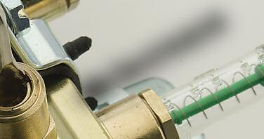
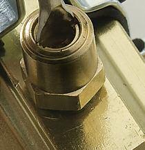
1 Page 1 Introduction The M-8200 Precision Manifolds are designed for use in Hydronic radiant panel heating and cooling applications. They are available in various sizes, configurations, and options with many accessories. Consult your local Representative for project specific requirements. In most cases the manifold is shipped in the box (right) loosely pre-assembled requiring tightening 1 only and then mounting before attaching the radiant tubing and performing system start-up procedures. Therefore, we are recommending the following sequence for complete installation of the manifold. A. Assemble (As Needed) and/or Tighten Manifold Components B. Mount Manifold C. Connect the Radiant Tubing D. Pressure Test E. Fill & Purge the System F. Balance the Manifold MANIFOLD ISOLATION VALVES A. Assemble Manifold Components (As Needed) ISOLATION VALVES W/THERMOMETER (M-8200T) PRECISSION ASSEMBLY (M-8200P) 1. A complete manifold consists of both a Supply and Return Header, each with a Precision Adapter Assembly (M-8200P manifolds) or End Plug, Header Isolation Valve and Manifold Mounting Brackets (see 1 above). These components are normally shipped together, loosely pre-assembled (1a) except the Header Isolation Valves, (see step 2) requiring tightening 1 only. Follow steps 2 through 5 below, as needed if assembly is required for reconfiguration, replacement, etc The Headers in the M-8200 Manifold Series are one piece, brass bar with built-in loop isolation valves (supply & return) and flow gauges (supply only) that require no assembly or tightening. 2. To mount the Manifold Isolation Valves, Thread the male end (1 or 1-1/4 threads) of the Tail Piece Nipple until tight 1, into the end of the manifold header (or into the Precision Adapter Assembly, if used) that is to receive the system supply / return distribution piping to / from the mechanical room. The Tail Piece Nipple can be tightened with a standard channel wrench (2a) or a spud (radiator) wrench using the spuds inside the Tail Piece Nipple (2b). The valve body is then threaded on to the other end of the Tail Piece Nipple with the union nut, until tight. Orient the valve body so that the handle can be operated comfortably once the manifold is mounted. The Manifold Isolation Valves are normally sold in pairs, the red-handle valve is for the supply manifold header and the blue-handle valve is for the return manifold header; both are installed the same way (2c). 3.Thread the male end (1 or 1-1/4 threads) of the End Plug until tight 1, into the end of the manifold header opposite the Manifold Isolation Valve (and the Precision Adapter Assembly, if used) (3). Repeat for both the supply (upper) and return (lower) manifold. 1 Note: The Precision Adapter Assembly, Manifold Isolation Valves and/or End Plugs seal together and to the manifold with an EPDM gasket (o-ring). One quarter (1/4) turn beyond hand-tight is normally sufficient to seal properly. If turning beyond 1/4 turn is required to align gauges and handles then do so, up to one (1) full turn beyond hand-tight. 1 SUPPLY HEADER RETURN HEADER END PLUG MANIFOLD MOUNTING BRACKETS Manifold arrives loosely pre-assembled in the box requiring tightening 1 only 1a 2a 2c VALVE BODY TAIL PIECE 2b HEADER 2 3
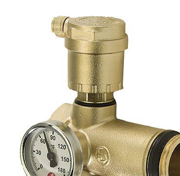
 consists of the Adapter, an Automatic Air Vent, Thermometer with Thermowell, Fill/Purge Valve and 1/2 plug (4).")

 Thread the male end (1 or 1-1/4 threads) of the Adapter until tight1, into the end of the manifold header that is to receive the system supply/return distribution piping to/from the mechanical")
 The Air Vent should always be installed onto the Adapter with the 1/4 x 1/2 Service Check Adapter (included with the Automatic Air Vent) in a vertical position.")
 Fill/Purge Valve.")
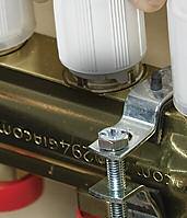
2 M-8200 Page 2 PRECISION Manifold Series A. Assemble Manifold Components (continued) 4 AIR VENT 4. The Precision Adapter Assembly (included with M-8000P manifold kits) consists of the Adapter, an Automatic Air Vent, Thermometer with Thermowell, Fill/Purge Valve and 1/2 plug (4). Do not install any components onto the Adapter until it is tightened1 in its final position and orientation. The Precision Adapter Assembly is normally sold in pairs; one for the supply manifold header and one for return manifold header. They are identical so they can be installed on either header and assembled following the procedures below (a through f). 4b SERVICE CHECK a) Precision Adaptor Body. (4a) Thread the male end (1 or 1-1/4 threads) of the Adapter until tight1, into the end of the manifold header that is to receive the system supply/return distribution piping to/from the mechanical room (4f). The Adapter should be properly aligned (oriented) so that the Air Vent port is facing up (vertical position). b) Automatic Air Vent. (4b) The Air Vent should always be installed onto the Adapter with the 1/4 x 1/2 Service Check Adapter (included with the Automatic Air Vent) in a vertical position. Thread the male end of the Service Check Adapter into an upper 1/2 port on the Precision Adapter until tight1. Thread the 1/4 male threads of the Air Vent into the Service Check Adapter hand tight only. 4a BODY 4e THERMOWELL 4c THERMOMETER 4d PLUG c) Fill/Purge Valve. (4c) Thread the male end of the Fill/Purge Valve into a lower 1/2 port of the Adapter until tight1. Orient the Fill/Purge Valve so that the handle can be operated comfortably once the manifold is mounted (photo). The opposite end of the Fill/Purge Valve has a 3/4 male garden hose thread (GHT) port and includes a brass cap with plastic tether. The plastic tether should slide over the end of the GHT port end of the Fill / Purge Valve. The brass cap, with EPDM gasket included, should be threaded on to the GHT port of Fill / Purge Valve until ready to use. FILL/PURGE VALVE BRASS CAP 4f d) Port Plug. (4d) The Adapter has three 1/2 ports. Thread the 1/2 Plug into the remaining open 1/2 port on the Adapter until tight1. e) Thermometer. (4e) Install the thermometer into the thermowell on the side of the adapter and lock into position with the set screw (newer models may use friction fit instead of set screw). f) Repeat steps a) through e) above for both the upper (supply) and lower (return) manifold. 5. Install the assembled manifold headers into the Manifold Mounting Brackets before mounting the brackets. Each Mounting Bracket includes two (2) sets of collars, one for the supply (upper) and one for return (lower) manifold headers (5). The Mounting Brackets are sold in pairs and every manifold should use both brackets for proper stabilization. The steel brackets are provided for secure mounting, proper alignment and isolation of vibration and noise. Do not install the manifold without these brackets. 5 5a COLLAR RUBBER ISOLATOR SCREW BRACKET a) Install the rubber isolation pads (included) on the top of the Mounting Bracket collars and the bottom face of the mounting bracket (5a). 5b 5c b) Attach one of the bottom halves of the collar assembly to the bracket with the hardware provided (short screw, washer, and lock washer) as shown (5b). c) Set the manifold header into the bottom half of the collar assembly (5c). The collar should be positioned around the manifold header between ports, at a distance from the end of the header sufficient to properly support the manifold when fully mounted in its operating position. Typically this is between the two circuits at either end of the header. On longer manifolds (10 to 12 circuits) this may be between the 2nd and 3rd circuits at either end of the header. d) Attach the upper half of the collar around the manifold header to the bottom half of the collar assembly by hooking one end into the slot on the bottom half of the collar, closest to the bracket, and threading the long screw down through the bottom collar into the threaded hole on the upper collar (5d). e) Repeat steps a. through d. above for both sets of collars upper (supply) and lower (return) on each bracket until the manifold is completely attached to the Manifold Mounting Brackets (5e). 5d 5e

 and periodic system")


 header 40\" (1.0 m) above the floor. 4. The manifold should never be mounted without the proper steel brackets.")

 before attaching the")
.")
 and help align the convergence of several tubing loop ends at")
 of radiant tubing.")
 are for PEX-AL-PEX tubing manufactured in compliance with ASTM F 1281.")

3 B. Mount the Manifold 1. The manifold location is normally determined during project design prior to installation. If the location was not previously selected or the selected location is no longer suitable due to project changes; a new location can be chosen based upon the following criteria: It should be located near the area (radiant panel) where the tubing is to be installed in order to avoid long circuit tails. It should be located so that it is accessible during and after project construction for initial start up procedures (Sections D through F) and periodic system maintenance and/or troubleshooting. 2. The manifold may be mounted in any orientation: vertical, horizontal, or even inverted; the only exception being that the header with the flow gauges must always be the supply header; receiving flow from the mechanical room and distributing it into the radiant panel (floor, ceiling, etc ). The best orientation for installation access and later maintenance and/or troubleshooting is in a vertical position on a wall. 3. The manifold should be installed using appropriate fasteners for the mounting surface and sized to fit the mounting holes in the steel brackets (6). The manifold should be mounted in its permanent location prior to installing the radiant tubing; adjustments after the tubing is connected, concrete is poured or floor coverings are installed, are very difficult. A temporary support may be built if the walls are not yet in place. Ensure that the manifold is level and has adequate clearance on the sides for the distribution piping connections to / from the mechanical room. The minimum clearance is 20" (51 cm) between the bottom of the manifold and the top of the finished floor (7). Ideally, the manifold will be mounted with the upper (supply) header 40" (1.0 m) above the floor. 4. The manifold should never be mounted without the proper steel brackets. The M-8200 Brass Manifolds are normally sold with the brackets. The steel brackets are provided for secure mounting, proper alignment and isolation of vibration and noise. Do not install the manifold without these brackets. Page 3 6 SUPPLY RETURN FASTENERS 7 C. Connect the Radiant Tubing 1. Slide the end of the tubing through the appropriately sized Tube Bend Support ( for 5/16, 3/8 & 1/2 tubing or for 5/8 & 3/4 tubing) before attaching the manifold connector (8). Position the 90 bend support on the tubing as it turns out of the floor, up into the manifold, typically 3 to 4 feet below the mounted manifold (9). At this approximate location, the bend support should extend several inches vertically above the finished floor height. Tubing Bend Supports protect the tubing as it transitions to and from the thermal mass (radiant floor) and help align the convergence of several tubing loop ends at the manifold location for a neat, professional appearance. 2. Manifold tube connectors (10) are not included with the manifold; they are sold separately. Use the appropriate tube connectors for the type and size (below a through g/h) of radiant tubing. Tube Connectors ( , -142, -143, -144, -145) are for PEX or PE-RT tubing manufactured in compliance with ASTM F 876 (PEX) or ASTM F 2623 (PE-RT). Composite Tube Connectors ( C, -144C, -145C) are for PEX-AL-PEX tubing manufactured in compliance with ASTM F Note: The Legend, M-8300 Stainless Steel series manifold tube connectors (and all other manufacturers tube connectors) are not compatible with the M-8000 Modular Brass or M-8200 Precision Brass Manifold 3. After the manifold is securely mounted in its final position, begin to connect the radiant tubing. The tubing should be connected to the manifold as it is being installed. For the best results, start each loop by attaching the tubing to the upper (supply) header (11). 4. Try to avoid crossing loops by attaching the end of the loop to the header port on the side (end) of the manifold closest to the area to be covered by that loop. It is very important to attach both ends of each loop to corresponding supply and return header ports on the manifold. For example, port 1 (to the far left as facing the manifold) on both the supply and return header must be attached the beginning and end of the same loop (12). 5. Each loop on the manifold should be labeled according to the area or room it covers on the project for future trouble shooting purposes. The installed length of each loop should also be noted on the manifold and recorded on the project plans for output and balancing calculations (see Section F; Balance the Manifold). Sticker labels are provided with the M-8000 Modular Manifold Kits (13). 8 Tubing Supports
 connections (14): a) Remove the protective red plastic cover from the manifold tube port.")
 Insert the barbed end adapter into the tubing until flush with the end of the tubing.")
 Hand-tighten the hex nut onto the male threads of the manifold port while supporting the tube and keeping the end adapter square in the port.")

 connections (15): a) Remove the protective red plastic cover from the manifold tube port.")
 ensuring that the o-ring is seated properly into the manifold port.")
4 C. Connect the Radiant Tubing continued 6. For 5/16, 3/8", 1/2" & 5/8" radiant tubing (Tube & Composite Tube Connectors) connections (14): a) Remove the protective red plastic cover from the manifold tube port. b) Ensure that the tubing is cut squarely using a proper tube cutter. c) Slide the hex nut (with the threads towards the manifold) onto the tubing. d) Slide the split ring washer onto the tubing. e) Insert the barbed end adapter into the tubing until flush with the end of the tubing. f) Place the end adapter into the selected port ensuring that the o-ring is seated properly into the manifold port. g) Hand-tighten the hex nut onto the male threads of the manifold port while supporting the tube and keeping the end adapter square in the port. It should turn on smoothly as the fitting is aligned (14a). h) Once the hex nut is hand tight, use a 1-1/8" (29 mm) wrench and turn it no more than 1/2 turn. Do not over tighten, as this may destroy the integral o-ring. Note: The Legend, M-8300 Stainless Steel Manifold tube connectors (and all other manufacturers tube connectors) are not compatible with the M-8000 Modular Brass or M-8200 Precision Brass series manifolds Page 4 14 HEX NUT SPLIT RING 14a 7. For 3/4" radiant tubing (Tube & Composite Tube Connectors) connections (15): a) Remove the protective red plastic cover from the manifold tube port. b) Ensure that the tubing is cut squarely using a proper tube cutter. c) Install the o-ring in the manifold bushing. Attach the manifold bushing to the selected manifold port (the hex end of the bushing closest to the header) ensuring that the o-ring is seated properly into the manifold port. Thread the bushing onto the port by hand until it stops. d) Slide the hex nut (with the threads towards the manifold) onto the tubing. e) Slide the split ring washer onto the tubing. f) Insert the barbed end adapter into the tubing until flush with the end of the tubing. g) Place the end adapter into the manifold bushing. h) Hand-tighten the hex nut onto the male threads of the manifold bushing while supporting the tube and keeping the end adapter square in the manifold bushing. It should turn on smoothly as the fitting is aligned (15a). i) Once the hex nut is hand tight, use a 1-1/2" (38 mm) wrench and turn it no more than 1/2 turn. Do not over tighten, as this may destroy the integral o-ring. Note: The Legend, M-8300 Stainless Steel Manifold tube connectors (and all other manufacturers tube connectors) are not compatible with the M-8000 Modular Brass or M-8200 Precision Brass series manifolds CAUTION: Do not use thread sealant tape or paste on these threads. These are parallel threads; sealing is achieved by the tapered brass threading and integral o-rings. 15 O-RING END SPLIT RING 15a


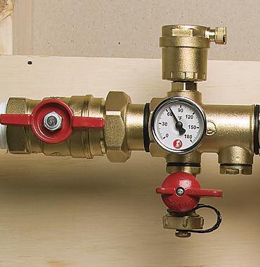
 Thread the male end (1 threads) of the Air Pressure Tester (T-820; sold separately) (16) into the female end of the installed supply Manifold Isolation Valve (red handle) (16a).")
5 M-8200 Page 5 D. Pressure Test 1. After the radiant tubing has been installed, but before it is covered, a pressure test should be performed on the manifold with all Circuit Isolation and Balancing Valves (both supply and return header) open so that the tubing and manifold connections can be checked for leaks. This pressure test can be performed with either air or water depending upon availability and/or local code requirements and is typically done prior to connecting the system supply/return distribution piping to from the mechanical room. 16 T-820 Air Pressure Tester 2. Air Pressure Test a) Thread the male end (1 threads) of the Air Pressure Tester (T-820; sold separately) (16) into the female end of the installed supply Manifold Isolation Valve (red handle) (16a). The use of thread sealant (Teflon tape or paste) will help ensure that this connection is air tight. Make sure the supply Manifold Isolation Valve is open and the return Manifold Isolation Valve is closed so that the manifold and radiant tubing system is sealed closed. If using Precision Adapters with Fill/Purge Valves (included with M-8000P manifold kits), make sure these valves (both supply and return) are also in the closed position (16a). 16a 16b OR b) Fill the system with air through the Schrader valve on the Air Pressure Tester (T-820) to the required test pressure (continue to step 3 below for recommended test pressures) (16b). 2. Water Pressure Test (Manifolds utilizing Precision Adapter with Fill/Purge Valve; included with M-8000P manifold kits) CAUTION: When pressure testing with water, ensure that all precaution is taken to prevent the water from freezing. a) Follow steps 3 through 10 in the Fill & Purge the System section of these instructions to purge the air out of the system. b)once all of the air has been purged, fill the system with water to the required test pressure (continue to step 3 below for recommended test pressures). 3. Initially fill the system to a pressure the greater of 1.5 times the maximum operating pressure or 100 psi for 30 minutes. Check for leaks, especially at the connections. As the radiant tubing expands, restore pressure, first at 10 minutes into the test and again at 20 minutes. At the end of 30 minutes, a pressure drop of more than 7 psi indicates there is a leak in the system. 4. After 30 minutes, restore the system to test pressure (if necessary), and then maintain pressure for a minimum of 2 hours. At the end of 2 hours, a pressure drop of more than 5 psi indicates there is a leak in the system. 5. After 2 hours, reduce the system pressure to psi, and then maintain this pressure during the remainder of building construction up to the time at which the system is filled. The system should be monitored during installation of the thermal mass, floor coverings and/or any time where floor penetrations may be necessary. 6. If a leak is present as determined by any step above (3 through 5), visually inspect the system to identify the location and then perform the necessary repairs. A soap and water mix solution can be poured onto the outside of the tubing and connections at potential leak areas to help identify leaks in systems under air pressure test. Upon completion of repairs, repeat the pressure test procedures from the beginning.


.")


. 4.")
.")


; turn the valve head with the 5 mm hex key")
 are")

.")


6 M-8200 E. Fill & Purge the System (Manifolds utilizing Precision Adapter with Fill/Purge Valve; included with M-8000P manifold kits) 1. Before the system is ready for operation 3 it must be filled with the proper fluid media and purged of air. The proper fluid is determined during design of the system, typically clean, de-ionized water or a water/ glycol mixture depending upon the required level of freeze protection and/or corrosion inhibitors. If using a water/glycol solution, mix the glycol into the water thoroughly prior to filling the system. Follow the glycol manufacturer s instructions for proper usage and installation. 2. A complete system fill/purge procedure normally starts in the mechanical room with the boiler and near boiler piping, followed by the distribution (zone) piping to / from the radiant manifolds (17). In smaller systems the manifolds and radiant tubing can be filled and purged with the distribution piping from the mechanical room. Larger systems, especially those with zones on upper levels, require that the manifold and radiant tubing is filled and purged at the manifold one loop at a time. These instructions are for operation of the manifold during the fill and purge of the manifold and radiant tubing. 3. Make sure the Manifold Isolation Valves (both supply and return) are closed so that the manifold and radiant tubing is isolated from the rest of the system (18). 4. Close all Circuit Isolation Valves on each loop of the return header, by turning the large white handle clockwise until it stops (19). Remove the protective clear plastic cover before operating the valve. 5. Verify that all Balancing Valves on each loop of the supply header are fully open (they are normally shipped in the open position). To open the Balancing Valves: loosen the Memory Stop and position it at the outer most setting by un-threading it counter -clockwise with the 10 mm flat head tool provided or a flat tip screw driver, until it stops (20a); turn the valve head with the 5 mm hex key provided, counter-clockwise until it is un-threaded to its outer most position (20b). 6. Make sure the Fill/Purge Valves on the Precision Adapters (both supply and return) are closed (21). Un-thread (counter-clockwise) the brass cap from the GHT ports (22). 7. Attach a fill hose from the water supply source to the GHT port on the Fill/Purge Valve of the supply header. Attach a drain hose to the same port on the Fill/Purge Valve of the return header (23). Place the Drain hose in a bucket of water, or filling media (24). 8. Turn on the water supply or filling pump and open the Fill/Purge Valve on the supply header and then open the Fill/Purge Valve on the return header. 9. Purge the air out of each loop in a logical order, one at a time, closing each loop after it has been purged, before opening the next. Open the Circuit Isolation Valve for the first loop, by turning the large white handle counter-clockwise until it stops (25). Air should start to sputter out of the drain hose. When the sputtering stops and a steady stream of water flows out of the drain hose; close the Circuit Isolation Valve of the first loop. 10. Repeat step 9, for each of the remaining loops. After the last loop has been purged, open the Circuit Isolation Valve for all of the loops and let any residual air purge out of the manifold. 11. Close the Fill/Purge Valve of the return header and let the system fill to operating pressure (typically 12 to 15 psi); then close the Fill/Purge Valve on the supply header. Turn off the water supply source or filling pump. 12. Make sure also, that the Automatic Air Vents (if used) on the Precision Adapters are open so that any small pockets of air remaining in the system are vented during normal operation. The Automatic Air vents can be opened by turning the cap counter-clockwise (26). 13. Disconnect the fill and drain hoses and cover the GHT ports on the Fill / Purge Valves (both supply and return) with the brass cap by threading it on (clockwise) (27). The Manifold Isolation Valves can now be opened and the system is ready for operation and/or balancing. 3 Note: Manifold Actuators ( , sold separately) should not be mounted on the manifold until after the system has been filled, purged and balanced. They should be mounted as the very last step before system operation. Their installation requires the removal of the Circuit Isolation Valve handles on the return header. Follow the installation instructions provided with the Actuators. Page a b 25

, the fluid flow rates in")

, as often construed. 2.")


 so")

. 5.")
.")


,")


. 8.")
 the Balancing Valve with the 5 mm hex key provided (32).")


7 F. Balance the Manifold The required flow rate for each loop is calculated during system design directly from the heat output (Btu/hr) and T (delta T; temperature difference beginning to end) requirements of that loop. In order for the system to function properly (to be balanced ), the fluid flow rates in each loop must be set to match the system design flow rates. The design flow rates of a given manifold may or may not be the same on each loop, therefore, balancing the manifold does not necessarily mean that the gauges on each loop should be set to the same reading (flow rate), as often construed. 2. To set the flow rate for each loop, follow steps 3 through 9, below. The system must be filled, purged and generally ready for operation, with the exception of manifold actuators 3, if required. All pumps for all zones in the system must be operational for these procedures, but it is not necessary to have heated or chilled fluid in the system. 3. Turn the entire system on and set the controls (thermostats, zone controls, relays, etc ) so that all zones are calling (all pumps are running and/or all zone valves are open) to simulate full design conditions. 4. Make sure the Manifold Isolation Valves (both supply and return) are open and that the manifold and radiant tubing are receiving full flow (28). 5. Male sure all Circuit Isolation Valves on each loop of the return header are open. They can be opened by turning the large white handle counter-clockwise until it stops (29). Remove the protective, clear, plastic cover before operating the valve. 6. Verify that all Balancing Valves on each loop of the supply header are fully open (they are normally shipped in the open position). To open the Balancing Valves: loosen the Memory Stop and position it at the outer most setting by un-threading it counter -clockwise (30a) with the 10 mm flat head tool provided or a flat tip screw driver, until it stops; turn the valve head with a 5 mm hex key (provided), counter-clockwise until it is un-threaded to its outer most position (30b). 7. The flow rate of each loop is indicated on its corresponding flow gauge, located on the top of the supply header. Remove the protective black plastic covers on each gauge. The scale on each gauge reads from 0 to 2 gpm with 0 gpm at the top of the gauge. The colored indicator rests at the top of the gauge with no flow and lowers down the scale as the flow increases (31). 8. Adjust the flow rate of each loop by closing (clockwise, to reduce flow) and opening (counter-clockwise, to increase flow) the Balancing Valve with the 5 mm hex key provided (32). The total range of the Balancing Valve from fully open to fully closed, is 2-1/2 to 3 turns. Be careful to not over tighten the valve when closing. 9. Start with the loop that requires the lowest flow rate and set that loop to the required flow plus 50%. Proceed to the loop with the next highest flow requirement and set that loop as close as possible to the required flow rate. Continue to the next loop in similar fashion until all loops have been set to their required flow rates. Note that after each loop is adjusted, the flow rates previously set for other loops may change. It is common for each loop to require multiple adjustments before all loops on the manifold are properly balanced. 10. Once all of the Balancing Valves on the manifold have been set for their required flow rates, the built in Memory Stops can be set to mark the position of the Balancing Valve. This step is for convenience, should the position of the Balancing Valve change (maintenance, tampering, etc ), it can easily be returned to the original set up position marked by the Memory Stop. It is not necessary to set the Memory Stop for the manifold to perform properly. The Memory Stop can be adjusted with the 10 mm flat head tool provided or a flat tip screw driver, by rotating it clockwise to close it against the valve head or counter clockwise to open it (33). 11. Repeat the balancing procedures as outlined in steps 3 through 9 above for all manifolds in the system. The manifold is now ready for operation and/or installation of zone actuators 3, as required. 3 Note: Manifold Actuators ( , sold separately) should not be mounted on the manifold until after the system has been filled, purged and balanced. They should be mounted as the very last step before system operation. Their installation requires the removal of the Circuit Isolation Valve handles on the return header. Follow the installation instructions provided with the Actuators. Page a increase open close decrease Memor y Stop b
Manifold Isolation Valves
 300 N. Opdyke Rd. Introduction The Stainless Manifolds are designed for use in Hydronic radiant panel heating and cooling applications. They are available in various sizes, configurations, and options
M-8100EP. Installation Guide ENGINEERED PLASTIC MANIFOLD SERIES. Introduction. A. Assemble Manifold Components
 Introduction The Pro Manifolds with Integrated adaptor are designed for use in Hydronic radiant panel heating and cooling applications. They are available in various sizes, configurations, and options
HKV 1 1/4 in. Brass Manifold Product instructions. Construction Automotive Industry
 HKV 1 1/4 in. Brass Manifold Product instructions www.rehau.com Construction Automotive Industry SCOPE This guide provides instruction regarding HKV 1 1/4 in. manifold installation and operation. Manifolds
PRO-BALANCE 1 1/4 IN. BRASS MANIFOLD. Product Instructions
 PRO-BALANCE 1 1/4 IN. BRASS MANIFOLD Product Instructions CONTENTS 1. Scope 3 2. Product Overview 3 3. Technical Data 5 4. Mounting the Manifold 7 5. Installing RAUPEX Pipes 8 6. Flushing and Filling Radiant
MrPEX 1 ½ " Brass Manifold Installation Guide
 MrPEX 1 ½ " Brass Manifold Installation Guide Design MrPEX 1 ½" Brass Manifold is made from high quality alloy extruded and chrome plated after machining, and is offered in 2 through 12 loop configurations.
MrPEX 1 ¼ Stainless Steel Manifold. Installation Guide
 MrPEX 1 ¼ Stainless Steel Manifold Installation Guide Design MrPEX 1 ¼ Stainless Steel Manifold is made from high quality stainless steel, and is offered in 2 through 12 loop configurations. The manifold
1" QickZone Modular Brass Manifold Installation Instructions Parts List
 Parts List QHCMKIT5 1" Manifold Supply End Modules with Lock Shield and Flow Meter QHMODAK: Adjustment Key QHMAVKIT5: Manual Air Vent 1" Manifold Return End Modules with Manual Shut Off QHLABELS: Labels
Product Instructions. Mixing Station. Features. Specifications. Materials
 Mixing Station The Viega Mixing Station provides supply water temperature modulation when connected to a variety of heat sources such as conventional or condensing boilers, water heaters, or geothermal
comfort, safety and convenience
 PRODUCT CATALOG MARCH 2011 Plumbing Systems Fire Sprinkler Systems Flawlessly moving water to provide the ultimate in comfort, safety and convenience for residential and commercial applications. That s
MrPEX 1 ¼ Stainless Steel Manifold Installation Guide
 MrPEX 1 ¼ Stainless Steel Manifold Installation Guide Design MrPEX 1 1/4 Stainless Steel Manifold is made from high quality stainless steel, and is offered in 2 through 12 loop configurations. The manifold
GTFLOW EXTENSION MANIFOLD ASSEMBLY INSTRUCTIONS
 Page 1 of 5 Step 1: ASSEMBLE THE MAIN MANIFOLD AND MANIFOLD EXTENSION KIT First and very important step is to properly connect the main manifold and the manifold extension kit together by using the two
Roth NP Manifold System Installation Instructions
 Roth Industries, Inc. 268 Bellew Avenue South Watertown, NY 360 Ph. 35-755-0 Fax 35-475-0200 www.roth-usa.com info@roth-usa.com ) Product description Constructed of heavy wall extruded nickel plated brass
Composite PEX-AL-PEX Tubing
 04/01/11 page 1.1 Composite PEX-AL-PEX Tubing List Per Foot 40190F ½ Composite Tubing x 200.62 40190 ½ Composite Tubing x 250.62 40190A ½ Composite Tubing x 300.62 40190B ½ Composite Tubing x 1000.62 40192
CHOOSING YOUR MANIFOLD & LOCATION
 CHOOSING YOUR MANIFOLD & LOCATION THOUGHTS ON ZONING The function of a manifold is to distribute the correct flow to each loop to meet its specific heating load. This is achieved by balancing each loop
Product Information. Brass Manifolds. Version A
 Product Information Brass Manifolds Version A Introduction Infloor offers a complete line of brass manifolds for radiant heating applications. This guide explains the how the manifolds work, the setup
DA Series Diaphragm Valve
 DA Series Diaphragm Valve Service Instructions Pneumatically Actuated Valve Toggle Valve Valve Valve Valves are shown with tube butt weld ends. These instructions also apply to DA series valves with any
LEAK TEST PROCEDURE MRTALPCH611LDC REMOTE READY LIFTERS W/ 3 BUTTON CONTROL APPLICABLE TO LIFTERS WITH SERIAL NUMBERS GREATER THAN #
 LEAK TEST PROCEDURE MRTALPCH611LDC REMOTE READY LIFTERS W/ 3 BUTTON CONTROL APPLICABLE TO LIFTERS WITH SERIAL NUMBERS GREATER THAN # 20100742 TESTING AND MAINTENANCE MUST BE DONE BY A QUALIFIED PERSON
Installation Guidelines
 STYLE No. EAXS32 EAXS33 EAXS34 EAXS35 STYLE No. EAHS32 - sold separately EAHS33 - sold separately EAHS34 - sold separately EAHS35 - sold separately 19 1 /4" 8" 9" 9" 3" In the State of Massachusetts, all
Installation, commissioning and servicing instructions
 CALEFFI www.caleffi.com NA88156 GeoCal geothermal manifolds Installation, commissioning and servicing instructions 110 Series Function The GeoCal pre-assembled manifold for ground-source geothmal loops
Calibration and Switching Module. User s Manual. A Swagelok Pre-Engineered. Subsystem. Pre-engineered subsystems available in weeks, not months.
 Calibration and Switching Module User s Manual A Swagelok Pre-Engineered Subsystem Pre-engineered subsystems available in weeks, not months. Field-tested design ensures optimum system performance. Contents
Fisher 657 Diaphragm Actuator Sizes and 87
 Instruction Manual 657 Actuator (30-70 and 87) Fisher 657 Diaphragm Actuator Sizes 30 70 and 87 Contents Introduction... 1 Scope of Manual... 1 Description... 2 Specifications... 2 Installation... 3 Mounting
Valve Box and Valve Accessories G4315A, G4316A, G4317A
 Valve Box and Valve Accessories G4315A, G4316A, G4317A Installation Guide The G4315A, G4316A, and G4317A accessories consist of separate kits depending on the custom configuration ordered. These kits may
I-317. AWWA Check Valves WARNING INSTALLATION AND MAINTENANCE INSTRUCTIONS SERIES 317 WARNING
 Read and understand all instructions before attempting to install, remove, adjust, or perform maintenance on any Victaulic piping products Wear safety glasses, hardhat, and foot protection. Failure to
Installation Instructions
 Installation Instructions SELECTRONIC PROXIMITY TOILET CONCEALED FLUSH VALVE. &. GPF Certified to comply with ASME A..M 00 AS America, Inc. Concealed Flushometer for -/" Top or Back Spud Bowls MODEL NUMBERS
Installation Instructions
 TIMES SQUARE Spread Lavatory Faucet with Speed Connect Drain Installation Instructions 8.80 8.8 Congratulations on purchasing your American Standard faucet with Speed Connect drain, a feature found only
180 Lake Ave North Paynesville, MN Phone: MASTER MANUFACTURING MASTER GARDNER
 180 Lake Ave North Paynesville, MN 56362 Phone: 1-800-864-1649 www.master-mfg.com MASTER MANUFACTURING MASTER GARDNER Part Number PCD-E3-009B-MM Rev 2 Dec. 2012 Note: Do not return product to the distributor/dealer
Thermo-Bob 3 Installation Manual: KLR650E (2008 and newer)
") Thermo-Bob 3 Installation Manual: KLR650E (2008 and newer) Thank you for purchasing the Thermo-Bob 3 radiator bypass system for the KLR650. Since the KLR already has a doohickey, it seemed that this thingamabob
Thermo-Bob 3 Installation Manual: KLR650E (2008 and newer) Thank you for purchasing the Thermo-Bob 3 radiator bypass system for the KLR650. Since the KLR already has a doohickey, it seemed that this thingamabob
This catalog contains the following geothermal accessory products and specification guides:
 f o r r e s i d e n t i a l s y s t e m s Geothermal systems offer an effective way to cut utility costs while ensuring comfort. Heat Controller s line includes two stage and single stage geothermal heat
For assistance call T&M. Tubing and manifolds. installation guide
 For assistance call 1.877.338.5493 1 06.17 T&M Tubing and manifolds installation guide 2 Table of contents For assistance call 1.877.338.5493 3 Manifold diagram Page 4 Manifold installation Page 5 Tubing-to-manifold
House Hydrant Installation Instructions
 House Hydrant Installation Instructions Please read all instructions and warnings before installing. WARNING Failure to turn off water supply prior to installation can result in personal injury or damage
INSTALLATION INSTRUCTIONS
 28 INSTALLATION INSTRUCTIONS SECTION - AIR SPRING SECTION 2 - AIR ACCESSORY 2-5 ! IMPORTANT PLEASE DON T HURT YOURSELF, YOUR KIT OR YOUR VEHICLE. TAKE A MINUTE TO READ THIS IMPORTANT INFORMATION. This
Suspension Leveling Kits HIGH LOW REGULAR. .f. KT ASSEMBLY AND USAGE GUIDE
 Suspension Leveling Kits LOW.f. REGULAR - HIGH t KT 192299 ASSEMBLY AND USAGE GUIDE INTRODUCTION ROCK RIDE Air suspension kits are designed to replace conventional steel springs or shock absorbers of your
VHM-P (Non-Locking) and VHM-PL (Locking) Variable Height Arm with Slide-In Mounting Plate
 and VHM-PL (Locking) Variable Height Arm with Slide-In Mounting Plate") 3875 Cypress Drive Petaluma, CA 94954 800.228.2555 +1.707.773.1100 Fax 707.773.1180 www.gcx.com VHM-P (Non-Locking) and VHM-PL (Locking) Variable Height Arm with Slide-In Mounting Plate (Refer to qualified
3875 Cypress Drive Petaluma, CA 94954 800.228.2555 +1.707.773.1100 Fax 707.773.1180 www.gcx.com VHM-P (Non-Locking) and VHM-PL (Locking) Variable Height Arm with Slide-In Mounting Plate (Refer to qualified
1501 Industrial Way N., Toms River, NJ Fax: PACKING LIST MUSTANG LONG TUBE HEADERS (M30000)
") 2/18/04 1501 Industrial Way N., Toms River, NJ 08755 732-349-2109 Fax:732-244-0867 ADVANCED - Installation requires professional-type tools and advanced automotive-service skills. If you lack experience
2/18/04 1501 Industrial Way N., Toms River, NJ 08755 732-349-2109 Fax:732-244-0867 ADVANCED - Installation requires professional-type tools and advanced automotive-service skills. If you lack experience
DL/DS Series Diaphragm Valve
 DL/DS Series Diaphragm Valve Service Instructions DL Series (Lever Handle) Valve DS Series (Round Handle) Valve Valves are shown with tube butt weld ends. These instructions also apply to DL or DS series
TOYOTA VENZA 2009 TRAILER WIRE HARNESS Procedure
 Part Number: PT791-0T099 Kit Contents Item # Quantity Reqd. Description 1 1 Trailer Wire Harness Module 2 1 4-Flat Harness 3 1 Battery Power Wire Harness 4 1 Mounting Bracket, 4-Flat 5 2 Screw #10-24 6
INSTALLATION INSTRUCTIONS
 2807 INSTALLATION INSTRUCTIONS SECTION - AIR SPRING SECTION 2 - AIR ACCESSORY -6 ! IMPORTANT PLEASE DON T HURT YOURSELF, YOUR KIT OR YOUR VEHICLE. TAKE A MINUTE TO READ THIS IMPORTANT INFORMATION. This
Installation/Care/Use Manual
 Installation/Care/Use Manual Soft Sides Freeze Resistant Fountain EDFP217FPC Installer To assure you install this model easily and correctly, PLEASE READ THESE SIMPLE INSTRUCTIONS BEFORE STARTING THE INSTALLATION.
Standard Duty Oil Filter Relocation Kit (OC-8)
") 3430 Sacramento Dr., Unit D San Luis Obispo, CA 93401 Telephone: 805/544-8748 Fax: 805/544-8645 www.maximummotorsports.com Standard Duty Oil Filter Relocation Kit (OC-8) Filter Mount Installation 4. Remove
3430 Sacramento Dr., Unit D San Luis Obispo, CA 93401 Telephone: 805/544-8748 Fax: 805/544-8645 www.maximummotorsports.com Standard Duty Oil Filter Relocation Kit (OC-8) Filter Mount Installation 4. Remove
INSTALLATION INSTRUCTIONS
 INSTALLATION INSTRUCTIONS REAR DISC BRAKE CONVERSION KITS A112, A112-1 & A112-93 1979-93 FORD MUSTANG with 7.5" & 8.8" AXLES Thank you for choosing STAINLESS STEEL BRAKES CORPORATION for your braking needs.
Stainless-steel Manifold Assembly, 1" with Flow Meter Submittal Information Revision B: Sept. 4, 2014
 Stainless-steel Manifold Assembly, 1" with Flow Meter Revision B: Sept. 4, 2014 Manifold Material: Manifold Components: Stainless steel AISI304 Brass CW614N-UNI EN12164, CW617N-UNI EN12165 Manifold Body
Thermo-Bob 4 Installation Manual. TB4-KT4A Kit KTM 450 SX-F KTM 450 XC-F Husky FC450
 Thermo-Bob 4 Installation Manual TB4-KT4A Kit 2013-2015 KTM 450 SX-F 2013-2015 KTM 450 XC-F 2013-2015 Husky FC450 Watt-man.com October 2016 Thermo-Bob 4 Installation: TB4-KT4A Kit Proper installation is
TECHNICAL INSTRUCTIONS #11 REGULATOR Single Seat - Bronze Trim - Composition Disc
 Page 1 TI595CD A Watts Industries Co. TECHNICAL INSTRUCTIONS #11 REGULATOR Single Seat - Bronze Trim - Composition Disc VALVE DESCRIPTION TABLE OF CONTENTS The Powers #11 Regulator is a self-actuating
PSR-HP-3000 MANUAL HAND PUMP INTERNAL LIQUID CAPICITY MAXIMUM OUTPUT PRESSURE PsiG (BarG) GALLONS (LITERS) 3000 (207) 5 (19)
 GALLONS (LITERS) 3000 (207) 5 (19)") PAGE 1 OF 6 P-SERIES HAND PUMP OPERATING INSTRUCTIONS WARNING: PRESSURE TESTING IS INHERENTLY DANGEROUS. STRICT ADHERENCE TO THESE OPERATING INSTRUCTIONS AND INDUSTRY SAFETY PRACTICES COULD PREVENT INJURY
PAGE 1 OF 6 P-SERIES HAND PUMP OPERATING INSTRUCTIONS WARNING: PRESSURE TESTING IS INHERENTLY DANGEROUS. STRICT ADHERENCE TO THESE OPERATING INSTRUCTIONS AND INDUSTRY SAFETY PRACTICES COULD PREVENT INJURY
INSTALLATION INSTRUCTIONS
 INSTALLATION INSTRUCTIONS REAR DISC BRAKE CONVERSION KIT A158 1994-97 Dodge Ram 1500 (2WD & 4WD) and REAR DISC BRAKE CONVERSION KIT A158-1 1998-01 Dodge Ram 1500 (2WD & 4WD) Thank you for choosing STAINLESS
INSTALLATION INSTRUCTIONS
 INSTALLATION INSTRUCTIONS Part # 751-FP2500 IMPORTANT INFORMATION This Jagg oil cooler must be installed following these instructions. Read the easy-to-follow instructions fully prior to starting the installation
Installation Instructions
 TROPIC Spread Lavatory Faucet with EverClean Finish & SpeedConnect Drain Installation Instructions 708.80 Congratulations on purchasing your American Standard faucet with EverClean finish and Speed Connect
INSTALLATION INSTRUCTIONS STUDIO S
 INSTALLATION INSTRUCTIONS STUDIO S 70.0 MONOBLOCK LAVATORY FAUCET WITH SPEED CONNECT Thank you for selecting American Standard... the benchmark of fine quality for over 00 years. To ensure that your installation
PRESSURIZED DIATOMACEOUS EARTH FILTER SYSTEM
 PRESSURIZED DIATOMACEOUS EARTH FILTER SYSTEM This filter system is designed for use with aboveground and semi-inground swimming pools. DO NOT operate this filter system without adding D.E. as it will cause
I-799/79V Coil Components
 WARNING Read and understand all instructions before attempting to install any Victaulic products. Depressurize and drain the piping system before attempting to install, remove, or adjust any Victaulic
LEAK TEST PROCEDURE APPLICABLE TO DC3 INTELLI-GRIP LIFTERS MODELS MRT4-DC3, MRTA8-DC3, MRTALP8-DC3 AND PC/P1-DC3 SERIES
 LEAK TEST PROCEDURE APPLICABLE TO DC3 INTELLI-GRIP LIFTERS MODELS MRT4-DC3, MRTA8-DC3, MRTALP8-DC3 AND PC/P1-DC3 SERIES TESTING AND MAINTENANCE MUST BE DONE BY A QUALIFIED PERSON KEEP FOR FUTURE REFERENCE
IsoTherm FlowGuards Mini Ball Valves Gauges Aquastats Unions
 82 IsoTherm FlowGuards Mini Ball Valves Gauges Aquastats Unions 83 Adjustment knob (sets supply temperature) Mixing Valve 1 Male BSP Threads Mixing Point Supply Inlet from Boiler Temperature Gauge (indicates
Installation Instructions
 Installation Instructions MANUAL FLUSH VALVE,. GPF Exposed Flushometer for /" top spud Urinals Certified to comply with: ASSE 07 ANSI/ASME A.9. ADA Compliant 0 AS America, Inc. M9600 Rev.. MODEL NUMBERS
Jacobsen 600 Series Ransomes 700 Series
 Jacobsen 600 Series Ransomes 700 Series Parts List & Mounting Instructions Jodale Perry Printed: 2004/01 Standard Parts List Qty Description Photo L&R Rear Mounting Brackets L&R Front Mounting Brackets
Instruction Manual Includes:
 Instruction Manual Includes: Page 1: HydraHorse Installation for Basic 2- Horse System Part I: Tank, pump, and electrical supply Page 6: Page 9: Part II: Page Bowls, Brackets, Pipes and Fittings Installing
KAM IAS ISOKINETIC AUTOMATIC SAMPLER. User Manual IASMANUAL-0513 KAM CONTROLS, INC Ann Arbor Drive Houston, Texas USA
 An ISO 900 certified company TEL + 73 784-0000 FAX + 73 784-000 Email Sales@Kam.com KAM IAS ISOKINETIC AUTOMATIC SAMPLER PER API 8.2, ASTM D477 AND ISO 37 User Manual IASMANUAL-053 3939 Ann Arbor Drive
Table of Contents Introduction 3 Chapter 2: Operation 4 Chapter 3: Components 5 Chapter 4: Specifications 8
 Table of Contents Introduction 3 Application 3 Chapter 2: Operation 4 Manifold Function 4 Chapter 3: Components 5 Required Parts 5 Manifold without Actuators without Pressure Bypass Kit 5 Pump Kit (QHMPK_)
Installation Instructions
 Installation Instructions SELECTRONIC PROXIMITY DUAL FLUSH TOILET FLUSH VALVE. /. GPF,.8/. GPF Certified to comply with ASME A.9.M 00 AS America, Inc. M90 REV.. Exposed Flushometer for -/" Top Spud Bowls
Installation Instructions 7024
 HAMILTON Centerset Lavatory Faucet with EverClean Finish & Speed Connect Drain Installation Instructions 70 Congratulations on purchasing your American Standard faucet with the EverClean finish and Speed
INSTALL MANUAL. FOR ON LINE ORDERING- E Commerce Visit Our Website
 INSTALL MANUAL FOR ON LINE ORDERING- E Commerce Visit Our Website WWW.PRESSUREGUARD.COM Contact Information Technical Support: Chris@pressureguard.com Sales Support: Sales@pressureguard.com By Phone: 615-227-6024
Standard Duty Oil Filter Relocation Kit (OC-3)
") 3430 Sacramento Dr., Unit D San Luis Obispo, CA 93401 Telephone: 805/544-8748 Fax: 805/544-8645 www.maximummotorsports.com Standard Duty Oil Filter Relocation Kit (OC-3) Read all of the instructions before
3430 Sacramento Dr., Unit D San Luis Obispo, CA 93401 Telephone: 805/544-8748 Fax: 805/544-8645 www.maximummotorsports.com Standard Duty Oil Filter Relocation Kit (OC-3) Read all of the instructions before
MODEL NUMBER: MEDIUM DUTY ONBOARD AIR SYSTEM
 MODEL NUMBER: 10003 MEDIUM DUTY ONBOARD AIR SYSTEM IMPORTANT: It is essential that you and any other operator of this product read and understand the contents of this manual before installing and using
Milano AUTOMATIC FAUCET
 Milano AUTOMATIC FAUCET with Surround Sensor Technology Installation & Maintenance IMPORTANT: PLEASE READ ENTIRE INSTRUCTION BOOKLET BEFORE YOU BEGIN INSTALLATION! Looks Clean - Is Clean. AutoFaucet Parts
INSTALLATION AND COMMISSIONING MANUAL CONTENTS. Function. Important Product range Technical specifications
 28237 www.caleffi.com Circulation units for solar thermal systems Copyright 204 Caleffi 278-279 series INSTALLATION AND COMMISSIONING MANUAL CONTENTS Function Important Product range Technical specifications
CARTRIDGE FILTER SYSTEMS OWNER S MANUAL
 CARTRIDGE FILTER SYSTEMS OWNER S MANUAL Installation Operation Parts Designed, Engineered & Manufactured in the USA. 2017 Waterway Plastics 2200 East Sturgis Road, Oxnard CA 93030 Phone 805.981.0262 Fax
Installation Instructions
 Installation Instructions MANUAL FLUSH VALVE with BEDPAN WASHER For Use with -/" Top Spud Toilets 607.860 (.6gpf) 607.80 (.8gpf) Certified to comply with: ASSE 07 CSA B. ADA Compliant 0 AS America, Inc.
Wirsbo Radiant Heating System
 January 1, 2009 PAGE 413-1 Wirsbo Radiant Heating System A1180313 WIRSBO hepex Barrier Tube Cross Linked Polyethylene Heat Transfer tubing with EVOH Oxygen Diffusion Barrier 413-0150 5/16" Nominal hepex:
Installation Instructions JASMINE Spread Lavatory Faucet with the EverClean Finish & Speed Connect Drain
 Installation Instructions JASMINE 80. Spread Lavatory Faucet with the EverClean Finish & Speed Connect Drain Congratulations on purchasing your American Standard faucet with the EverClean finish and Speed
INTRODUCTION / TABLE OF CONTENTS
 1 2 INTRODUCTION / TABLE OF CONTENTS Step One About Level Track Mounting Kit: Omega Engineering s Level Track Kit is an adjustable mounting system for installing multiple level sensors vertically within
Welker Sampler. Installation, Operation, & Maintenance Manual. Model GSS-4HP
 Installation, Operation, & Maintenance Manual Welker Sampler Model GSS-4HP The information in this manual has been carefully checked for accuracy and is intended to be used as a guide to operations. Correct
StratoLauncher IV Assembly Instructions
 Tools required for assembly and items needed to launch rocket: An adjustable wrench (or a 14mm wrench), 4mm & 5mm hex wrench, and Phillips head screwdriver. A plastic (PET*) soda bottle, nose cone, water,
Installation Instructions
 Installation Instructions for /" top spud Urinals Certified to comply with: ASSE 07 ANSI/ASME A.9. ADA Compliant 0 AS America, Inc. MODEL NUMBERS 0.0 FOR TOP SPUD APPLICATIONS CLOG RESISTANT Self-cleaning
Installation Instructions
 Installation Instructions SELECTRONIC PROXIMITY CONCEALED URINAL FLUSH VALVE.0, 0. & 0. GPF Certified to comply with ASME A.9. 07 AS America, Inc. MODEL NUMBERS 0B.X0 0B.X0 0B.X0 CAUTION: Use only American
NAME OF PAGE. Opening paragraph. header. header. header. header PAGE 1
 NAME OF PAGE PAGE 1 Opening paragraph header header header header 1 1 1 1 2 2 2 2 3 3 3 3 4 4 4 4 5 5 5 5 6 6 6 6 7 7 7 7 8 8 8 8 TABLE OF CONTENTS PAGE 1 PAGE 2-4 Infloor Bpex, Pex Al Pex Tubing and Potable
LEAK TEST PROCEDURE DC CHANNEL LIFTERS SINGLE VACUUM SYSTEMS TESTING AND MAINTENANCE MUST BE DONE BY A QUALIFIED PERSON KEEP FOR FUTURE REFERENCE
 LEAK TEST PROCEDURE DC CHANNEL LIFTERS SINGLE VACUUM SYSTEMS TESTING AND MAINTENANCE MUST BE DONE BY A QUALIFIED PERSON KEEP FOR FUTURE REFERENCE TST-008 Rev. 2013-048 Page 1 of 10 THIS PAGE INTENTIONALLY
Defender Series. Overfill Prevention Valve. Automatic Shutoff for USTs. Installation, Operation and Maintenance Series
 Defender Series Overfill Prevention Valve Automatic Shutoff for USTs Installation, Operation and Maintenance 708-590 Series For use in 4" gravity-fill applications only 25-370 Gallons per Minute flow Compatible
CALEFFI. Pre-assembled distribution manifolds for radiant panel systems. series 663 & /05 NA. Function
 Pre-assembled distribution manifolds for radiant panel systems series & / NA Function Distribution manifolds for radiant panel systems are used to optimally distribute the heating fluid in floor heating
Installation & Operating Manual
 Installation & Operating Manual 25INV-M 1/17 Edition NV Series Vertical Booster Stainless Steel Multistage Centrifugal Pump Congratulations On Your Choice In Purchasing This Webtrol Pump Its Quality is
123 Industrial Loop Road Paynesville, MN Phone:
 123 Industrial Loop Road Paynesville, MN 56362 Phone: 1-800-864-1649 www.master-mfg.com Note: Do not return product to the distributor/dealer for warranty work. Call Master Manufacturing at (800) 864-1649
Instruction Manual For MrPEX Composite Radiant Manifold
 Instruction Manual For MrPEX Composite Radiant Manifold For Radiant Floor Heating and Cooling Applications Read manual before use! Observe all safety information! Keep manual for future use! A Division
Instruction Manual for HSPA Take-Up Units
 Installation Instruction Manual for HSPA Take-Up Units Warning: To ensure the drive is not unexpectedly started, turn off and lockout the power source before proceeding. Failure to observe these precautions
INSTALLATION/OPERATING INSTRUCTIONS TEMPERING VALVE HOT C GASKET STANDARD PIPE TAP MIXED HOT COLD HOT INLET INLET 3/4" 1" 1 1/4" 3/4" 1 1/4"
 INSTALLATION/OPERATING INSTRUCTIONS NIPPLE A MIXED OUTLET INSERT "O" RING MIXER VALVE BODY COLD OUTLET B SPRING COLD INLET C O L D FAIRFIELD, N.J. R H O T INLET GUIDE PISTON C GASKET BONNET ADJUSTING SCREW
ENGINE DRIVEN COMPRESSOR --- GM 4.3, 5.0, 5.7 ENGINES. (90-95 GM fullsize trucks and S10s)
") ENGINE DRIVEN COMPRESSOR --- GM 4.3, 5.0, 5.7 ENGINES (90-95 GM fullsize trucks and S10s) NOTE: Determine your proper belt length on Step 14 before beginning the installation. 1 & 2 Rotate the idler pulley
ENGINE DRIVEN COMPRESSOR --- GM 4.3, 5.0, 5.7 ENGINES (90-95 GM fullsize trucks and S10s) NOTE: Determine your proper belt length on Step 14 before beginning the installation. 1 & 2 Rotate the idler pulley
INSTALLATION INSTRUCTIONS
 INSTALLATION INSTRUCTIONS PERFORMANCE AT THE WHEELS KIT W125-42 GM 10 & 12 Bolt Rear Axles with Staggered or non-staggered Shocks with C-Clips Thank you for choosing STAINLESS STEEL BRAKES CORPORATION
METERING VALVE 2" STEM GUIDED
 2" STEM GUIDED All Rights Reserved. All contents of this publication including illustrations are believed to be reliable. And while efforts have been made to ensure their accuracy, they are not to be construed
A B C D E F. Tools Required (supplied by others)
") Page 1 of 17 Parts List Below Deck Automatic Retractable Security Cover Kit (1) Tube End Bearing Plate (A) (1) Rope Reel and Cover Drum Motor Assembly (B) (1) Cover Drum (1) Pulley Support Channel (2)
Page 1 of 17 Parts List Below Deck Automatic Retractable Security Cover Kit (1) Tube End Bearing Plate (A) (1) Rope Reel and Cover Drum Motor Assembly (B) (1) Cover Drum (1) Pulley Support Channel (2)
OWNER S MANUAL D.E. CARTRIDGE. Installation Operation Parts. Models PCDE-30 PCDE-40
 D.E. CARTRIDGE OWNER S MANUAL Installation Operation Parts Models PCDE-30 PCDE-40 2200 East Sturgis Road, Oxnard, CA 93030 Ph. (805) 981-0262 Fax (805) 981-9403 www.waterwayplastics.com waterway@waterwayplastics.com
INSTALLATION INSTRUCTIONS
 INSTALLATION INSTRUCTIONS REAR DISC BRAKE CONVERSION KIT A126-1 1973-87 CHEVROLET 1/2 TON 2WD Thank you for choosing STAINLESS STEEL BRAKES CORPORATION for your braking needs. Pleases take the time to
Installation Instructions Series Series
 PORTSMOUTH Spread Lavatory Faucet with Speed Connect Drain Congratulations on purchasing your American Standard faucet with Speed Connect drain, a feature found onlyon American Standard faucets. Recommended
Installation, Operation, and Maintenance Manual. Welker Automatic Insertion Corrosion Coupon Device Model AID-1CC
 Installation, Operation, and Maintenance Manual Welker Automatic Insertion Corrosion Coupon Device Model The information in this manual has been carefully checked for accuracy and is intended to be used
PEX Plumbing & Radiant Heating Systems
 PEX Plumbing & Radiant Heating Systems PEX0118 Customer Guide Effective January 1, 2018 Replaces All Previous Price Lists TABLE OF CONTENTS BY SECTION ZURN PEX PLUMBING PRODUCTS HOT/COLD POTABLE (NON-BARRIER)
Snow Melt EN_US_2014_V2.indb 171 2/7/ :18:52 AM
 171 Viega snow melting systems are complete hydronic solutions for residential, commercial and industrial applications. All it takes is ViegaPEX Barrier tubing installed in a concrete slab and the proper
Installation/Care/Use Manual
 Installation/Care/Use Manual EDFP210FPC EDFP214FPC EDFP217FPC Soft Sides Freeze Resistant Fountains EDFP210FPC EDFP214FPC EDFP217FPC Installer To assure you install this model easily and correctly, PLEASE
Installation Instructions
 Installation Instructions for -/" Top Spud Fixtures MODEL NUMBERS 607 Series 707 Series OPERATING PRESSURE: Overall Range: 0- psi ** Recommended: psi (flowing) - 80 psi (static) FLOW REQUIREMENT: gpm (9.6
Recommended Tools: 3/8 drive ratchet 3/8 drive 13mm socket 3/8 drive 15mm deep socket 10 3/8 ratchet extension Grommet pullers
 Please take time to read and understand these installation instructions. CORSA recommends that the installation of this system be performed by a qualified service center or professional muffler installer
Installation Instructions
 Spread Lavatory Faucet with the Speed Connect Drain Congratulations on purchasing your American Standard faucet with Speed Connect drain, a feature found only on American Standard faucets. Speed Connect
Installation, Operation and Maintenance Guide II NIBCO High Performance Butterfly Valves Series 6822 and 7822
 Installation, Operation and Maintenance Guide II NIBCO High Performance Butterfly Valves Series 6822 and 7822 Statements: NIBCO High Performance Butterfly Valves, Series 6822 and 7822, have been designed
Operation & Replacement Parts Manual
 ERGO-ARM II Operation & Replacement Parts Manual AEA-1212-A Pneumatic AEA-1212-M Mechanical A SUBSIDIARY OF AIMCO D.C Nutrunners Torque Measurement & Audit Equipment Articulating Arms Assembly Systems
Installation Instructions
 Installation Instructions SELECTRONIC CONCEALED TOILET FLUSH VALVE.,.8 &. GPF Certified to comply with ASME A.9. 0 AS America, Inc. MODEL NUMBERS 0B.XX Exposed Back Spud Concealed Back Spud Top Spud CAUTION:
Product Catalog. Just because it s in the floor doesn t mean it s INFLOOR.
 Product Catalog Just because it s in the floor doesn t mean it s INFLOOR www.infloor.com TABLE OF CONTENTS Tubing New Style Brass Manifolds & Related Components Current Brass Manifolds & Related Components